CN1287202C - Displaying apparatus and electronic apparatus with said device - Google Patents
Displaying apparatus and electronic apparatus with said deviceDownload PDFInfo
- Publication number
- CN1287202C CN1287202CCNB031453023ACN03145302ACN1287202CCN 1287202 CCN1287202 CCN 1287202CCN B031453023 ACNB031453023 ACN B031453023ACN 03145302 ACN03145302 ACN 03145302ACN 1287202 CCN1287202 CCN 1287202C
- Authority
- CN
- China
- Prior art keywords
- mentioned
- polarized light
- liquid crystal
- display
- display part
- Prior art date
- Legal status (The legal status is an assumption and is not a legal conclusion. Google has not performed a legal analysis and makes no representation as to the accuracy of the status listed.)
- Expired - Lifetime
Links
- 239000004973liquid crystal related substanceSubstances0.000claimsabstractdescription247
- 230000005540biological transmissionEffects0.000claimsabstractdescription42
- 230000003287optical effectEffects0.000claimsdescription35
- 230000008859changeEffects0.000claimsdescription25
- 238000006243chemical reactionMethods0.000claimsdescription14
- 239000006185dispersionSubstances0.000claimsdescription14
- 230000005684electric fieldEffects0.000claimsdescription12
- 238000010521absorption reactionMethods0.000claimsdescription7
- 239000007767bonding agentSubstances0.000claimsdescription3
- 238000009940knittingMethods0.000claims6
- 239000004568cementSubstances0.000claims2
- 230000007423decreaseEffects0.000abstractdescription11
- 230000015556catabolic processEffects0.000abstractdescription2
- 238000006731degradation reactionMethods0.000abstractdescription2
- 230000009467reductionEffects0.000abstractdescription2
- 230000010287polarizationEffects0.000description91
- 239000010410layerSubstances0.000description78
- 239000010408filmSubstances0.000description45
- 239000000758substrateSubstances0.000description24
- 239000000853adhesiveSubstances0.000description9
- 230000001070adhesive effectEffects0.000description9
- 239000000463materialSubstances0.000description9
- 238000000034methodMethods0.000description9
- 238000004040coloringMethods0.000description7
- 238000010586diagramMethods0.000description7
- 239000011159matrix materialSubstances0.000description6
- 239000011347resinSubstances0.000description6
- 229920005989resinPolymers0.000description6
- 230000000694effectsEffects0.000description5
- 239000000126substanceSubstances0.000description5
- 239000011521glassSubstances0.000description4
- 238000002834transmittanceMethods0.000description4
- 239000004988Nematic liquid crystalSubstances0.000description3
- 238000005286illuminationMethods0.000description3
- 239000010409thin filmSubstances0.000description3
- 239000004925Acrylic resinSubstances0.000description2
- 229920000178Acrylic resinPolymers0.000description2
- 239000002131composite materialSubstances0.000description2
- 230000006866deteriorationEffects0.000description2
- 239000003822epoxy resinSubstances0.000description2
- 229920000647polyepoxidePolymers0.000description2
- VYPSYNLAJGMNEJ-UHFFFAOYSA-Nsilicon dioxideInorganic materialsO=[Si]=OVYPSYNLAJGMNEJ-UHFFFAOYSA-N0.000description2
- 239000004986Cholesteric liquid crystals (ChLC)Substances0.000description1
- 230000009471actionEffects0.000description1
- 239000012790adhesive layerSubstances0.000description1
- 239000000956alloySubstances0.000description1
- 229910045601alloyInorganic materials0.000description1
- XAGFODPZIPBFFR-UHFFFAOYSA-NaluminiumChemical compound[Al]XAGFODPZIPBFFR-UHFFFAOYSA-N0.000description1
- 229910052782aluminiumInorganic materials0.000description1
- 230000015572biosynthetic processEffects0.000description1
- 238000000576coating methodMethods0.000description1
- 239000000470constituentSubstances0.000description1
- 230000009977dual effectEffects0.000description1
- 238000005401electroluminescenceMethods0.000description1
- 238000005516engineering processMethods0.000description1
- 230000008020evaporationEffects0.000description1
- 238000001704evaporationMethods0.000description1
- 150000002484inorganic compoundsChemical class0.000description1
- 229910010272inorganic materialInorganic materials0.000description1
- 238000009434installationMethods0.000description1
- 230000001678irradiating effectEffects0.000description1
- ORUIBWPALBXDOA-UHFFFAOYSA-Lmagnesium fluorideChemical compound[F-].[F-].[Mg+2]ORUIBWPALBXDOA-UHFFFAOYSA-L0.000description1
- 229910001635magnesium fluorideInorganic materials0.000description1
- 230000014759maintenance of locationEffects0.000description1
- 239000000203mixtureSubstances0.000description1
- 150000002894organic compoundsChemical class0.000description1
- 239000004033plasticSubstances0.000description1
- 229920006254polymer filmPolymers0.000description1
- 239000010453quartzSubstances0.000description1
- 230000004044responseEffects0.000description1
- 239000003566sealing materialSubstances0.000description1
- 229910052814silicon oxideInorganic materials0.000description1
- 229910052709silverInorganic materials0.000description1
- 239000004332silverSubstances0.000description1
- 239000002356single layerSubstances0.000description1
- 238000004544sputter depositionMethods0.000description1
- 230000001360synchronised effectEffects0.000description1
- 239000012780transparent materialSubstances0.000description1
- 238000007740vapor depositionMethods0.000description1
Images


Classifications
- G—PHYSICS
- G02—OPTICS
- G02F—OPTICAL DEVICES OR ARRANGEMENTS FOR THE CONTROL OF LIGHT BY MODIFICATION OF THE OPTICAL PROPERTIES OF THE MEDIA OF THE ELEMENTS INVOLVED THEREIN; NON-LINEAR OPTICS; FREQUENCY-CHANGING OF LIGHT; OPTICAL LOGIC ELEMENTS; OPTICAL ANALOGUE/DIGITAL CONVERTERS
- G02F1/00—Devices or arrangements for the control of the intensity, colour, phase, polarisation or direction of light arriving from an independent light source, e.g. switching, gating or modulating; Non-linear optics
- G02F1/01—Devices or arrangements for the control of the intensity, colour, phase, polarisation or direction of light arriving from an independent light source, e.g. switching, gating or modulating; Non-linear optics for the control of the intensity, phase, polarisation or colour
- G02F1/13—Devices or arrangements for the control of the intensity, colour, phase, polarisation or direction of light arriving from an independent light source, e.g. switching, gating or modulating; Non-linear optics for the control of the intensity, phase, polarisation or colour based on liquid crystals, e.g. single liquid crystal display cells
- G02F1/133—Constructional arrangements; Operation of liquid crystal cells; Circuit arrangements
- G02F1/1333—Constructional arrangements; Manufacturing methods
- G02F1/1347—Arrangement of liquid crystal layers or cells in which the final condition of one light beam is achieved by the addition of the effects of two or more layers or cells
- G—PHYSICS
- G02—OPTICS
- G02F—OPTICAL DEVICES OR ARRANGEMENTS FOR THE CONTROL OF LIGHT BY MODIFICATION OF THE OPTICAL PROPERTIES OF THE MEDIA OF THE ELEMENTS INVOLVED THEREIN; NON-LINEAR OPTICS; FREQUENCY-CHANGING OF LIGHT; OPTICAL LOGIC ELEMENTS; OPTICAL ANALOGUE/DIGITAL CONVERTERS
- G02F1/00—Devices or arrangements for the control of the intensity, colour, phase, polarisation or direction of light arriving from an independent light source, e.g. switching, gating or modulating; Non-linear optics
- G02F1/01—Devices or arrangements for the control of the intensity, colour, phase, polarisation or direction of light arriving from an independent light source, e.g. switching, gating or modulating; Non-linear optics for the control of the intensity, phase, polarisation or colour
- G02F1/13—Devices or arrangements for the control of the intensity, colour, phase, polarisation or direction of light arriving from an independent light source, e.g. switching, gating or modulating; Non-linear optics for the control of the intensity, phase, polarisation or colour based on liquid crystals, e.g. single liquid crystal display cells
- G02F1/133—Constructional arrangements; Operation of liquid crystal cells; Circuit arrangements
- G02F1/1333—Constructional arrangements; Manufacturing methods
- G02F1/1335—Structural association of cells with optical devices, e.g. polarisers or reflectors
- G02F1/133528—Polarisers
- G02F1/133536—Reflective polarizers
Landscapes
- Physics & Mathematics (AREA)
- Nonlinear Science (AREA)
- Mathematical Physics (AREA)
- Chemical & Material Sciences (AREA)
- Crystallography & Structural Chemistry (AREA)
- General Physics & Mathematics (AREA)
- Optics & Photonics (AREA)
- Liquid Crystal (AREA)
Abstract
Translated fromChinese
Description
Translated fromChinese技术领域technical field
本发明涉及显示装置及具备了该显示装置的电子设备,尤其涉及可将显示画面切换为镜面状态的显示体的构成。The present invention relates to a display device and electronic equipment equipped with the display device, and more particularly to a configuration of a display body capable of switching a display screen to a mirror state.
现有技术current technology
以往,通过将2个液晶面板重叠,可进行通常的显示状态与镜面状态的切换来构成的显示装置已为人们所知。比如,具有在具有与通常的液晶显示装置同样结构的显示部的观察侧设置显示切换部,在该显示切换部中,从显示部侧依次配置了反射型偏振光片、液晶面板、吸收型偏振光片的显示装置。在该显示装置中,显示切换部的反射型偏振光片使第1偏振光透过,使具有与该第1偏振光正交的偏振光轴的第2偏振光反射,液晶面板被构成为可对使第1偏振光转化为第2偏振光并透过的状态与使偏振光轴不变化而通过的状态进行切换,吸收型偏振光片比如使第1偏振光透过,对第2偏振光吸收。显示部使第1偏振光对显示切换部射出,由该第1偏振光构成所定的显示图像。Conventionally, a display device configured by stacking two liquid crystal panels to switch between a normal display state and a mirror state is known. For example, a display switching unit is provided on the viewing side of a display unit having the same structure as a common liquid crystal display device, and in this display switching unit, a reflective polarizer, a liquid crystal panel, and an absorption polarizer are sequentially arranged from the display unit side. Light sheet display device. In this display device, the reflective polarizer of the display switching part transmits the first polarized light and reflects the second polarized light having a polarization axis perpendicular to the first polarized light, and the liquid crystal panel is configured to be able to Switch the state where the first polarized light is converted into the second polarized light and transmit it, and the state where the polarization axis does not change and pass through. For example, the absorption polarizer allows the first polarized light to pass through, and the second polarized light absorb. The display unit emits the first polarized light to the display switching unit, and the first polarized light constitutes a predetermined display image.
在上述构成的显示装置中,显示切换部的液晶面板如果处于使偏振光轴不变化而透过的状态,则从显示部射出的第1偏振光透过反射型偏振光片,入射到液晶面板,按第1偏振光原样透过吸收型偏振光片并被观察,因而可以对显示部的显示形式进行视见(显示状态)。此外液晶面板如果处于使第1偏振光变为第2偏振光并透过的状态,由于从显示部射出的第1偏振光透过反射型偏振光片,入射到液晶面板后,变为第2偏振光,因而由吸收型偏振光片吸收,显示形式不被视见。此时,外光入射到装置后,外光透过吸收型偏振光片,成为第1偏振光,通过透过液晶面板,成为第2偏振光,因而通过由反射型偏振光片反射,再次透过液晶面板而变为第1偏振光,从吸收型偏振光片中通过。因而显示面被以镜面状视见(镜状态)。In the display device having the above configuration, if the liquid crystal panel of the display switching section is in a state where the polarization axis is transmitted without changing, the first polarized light emitted from the display section passes through the reflective polarizer and enters the liquid crystal panel. , the first polarized light is transmitted through the absorbing polarizer and observed, so the display form of the display unit can be seen (display state). In addition, if the liquid crystal panel is in the state of changing the first polarized light into the second polarized light and transmitting it, since the first polarized light emitted from the display part passes through the reflective polarizer and enters the liquid crystal panel, it becomes the second polarized light. Polarized light is thus absorbed by the absorbing polarizer and the displayed form is not seen. At this time, after the external light is incident on the device, the external light passes through the absorbing polarizer to become the first polarized light, and passes through the liquid crystal panel to become the second polarized light, so it is reflected by the reflective polarizer and then transmitted again. After passing through the liquid crystal panel, it becomes the first polarized light and passes through the absorbing polarizer. The display surface is thus seen as a mirror (mirror state).
然而在上述以往的显示装置中,由于在显示装置与镜状态的任意一种中,均可视见透过了设置于显示切换部的液晶面板的光,因而存在着易于发生显示切换部的表里两面等中的界面反射所引起的对比度降低、显示切换部的光学特性所引起的着色、视角特性的恶化、显示图像的模糊等的问题点。在任意一种情况下,在以往的显示装置中,都不能避免由显示部与显示切换部的2重结构所引起的显示质量的下降。However, in the above-mentioned conventional display device, since the light transmitted through the liquid crystal panel provided in the display switching part can be seen in any of the display device and the mirror state, there is a problem that the display switching part is likely to occur. Problems such as reduction of contrast due to interface reflection on the back and sides, coloration due to optical characteristics of the display switching part, deterioration of viewing angle characteristics, blurring of displayed images, etc. In either case, in conventional display devices, degradation of display quality due to the dual structure of the display unit and the display switching unit cannot be avoided.
本发明旨在解决上述问题点,其课题是提供在具有显示部与显示切换部的显示装置中,可抑制由于显示切换部的存在所引起的对比度降低、着色、视角变窄、模糊等显示质量下降的显示装置的新构成。The present invention aims to solve the above-mentioned problems, and its object is to provide a display device having a display unit and a display switching unit that can suppress display quality such as decrease in contrast, coloring, narrowing of the viewing angle, and blurring caused by the presence of the display switching unit. A new composition of the dropped display device.
发明内容Contents of the invention
为解决上述课题,本发明的显示装置的特征在于具有具有:显示部,其为形成显示状态而射出光;及显示切换部,其以与上述显示部的至少一部分重叠的方式配置在上述显示部的观察侧;上述显示切换部包含从上述显示部向观察侧依次配置的第1偏振光片、液晶面板、及第2偏振光片,上述第1偏振光片在使第1偏振光透过的同时,使具有与上述第1偏振光的偏振光轴交叉的偏振光轴的第2偏振光反射,上述液晶面板构成为可切换使上述第1偏振光变为上述第2偏振光而透过的状态与使入射的光的偏振光轴不发生变化而透过的状态,上述第2偏振光片使上述第1偏振光与上述第2偏振光中的任意一方透过,对另一方进行吸收或反射,上述显示部为形成上述显示状态而射出上述第1偏振光,上述显示部与上述显示切换部被光学接合。In order to solve the above-mentioned problems, the display device of the present invention is characterized by comprising: a display unit that emits light to form a display state; and a display switching unit that is arranged on the display unit so as to overlap at least a part of the display unit. The observation side; the above-mentioned display switching part includes a first polarizer, a liquid crystal panel, and a second polarizer arranged in order from the above-mentioned display part to the observation side, and the first polarizer transmits the first polarized light At the same time, the second polarized light having a polarization axis crossing the polarization axis of the first polarized light is reflected, and the liquid crystal panel is configured to switch the first polarized light into the second polarized light and transmit it. state and the state in which the polarization axis of the incident light is transmitted without changing, and the second polarizer transmits either one of the first polarized light and the second polarized light, and absorbs or absorbs the other. In reflection, the display unit emits the first polarized light to form the display state, and the display unit and the display switching unit are optically bonded.
通过显示部与显示切换部被光学接合,可抑制由于显示部与显示切换部的界面反射等,针对显示部显示形式的视见性(比如对比度)降低。通过显示部与显示切换部被互相光学接合,成为一种显示部与显示切换部的一方由他方支持的关系,因而可以提高刚性及强度,所以可以确保显示画面的平坦性,还可提高装置的耐冲击性。尤其是通过较薄地形成显示切换部,可提高显示部显示形式的视见性,即使由于较薄地形成而使显示切换部的刚性降低,通过由显示部支持可确保平坦性及耐冲击性。When the display unit and the display switching unit are optically bonded, it is possible to suppress a decrease in visibility (for example, contrast) of the display form of the display unit due to interface reflection between the display unit and the display switching unit. The display unit and the display switching unit are optically bonded to each other to form a relationship in which one of the display unit and the display switching unit is supported by the other, so the rigidity and strength can be improved, so the flatness of the display screen can be ensured, and the reliability of the device can also be improved. Impact resistance. In particular, by forming the display switch part thinly, the visibility of the display form of the display part can be improved, and even if the rigidity of the display switch part is reduced due to thin formation, flatness and impact resistance can be ensured by being supported by the display part.
在本发明中,上述显示部与上述显示切换部最好通过由粘合剂或接合剂组成的接合层被光学接合。由于显示部与显示切换部通过由粘合剂或接合剂组成的接合层被光学接合,可以基于该粘结力及接合力在互相支持的状态下对显示部与显示切换部进行固定,因而可以进一步提高平坦性的维持强度及刚性。In the present invention, it is preferable that the display portion and the display switching portion are optically bonded via a bonding layer composed of an adhesive or an adhesive. Since the display unit and the display switching unit are optically bonded through a bonding layer composed of an adhesive or an adhesive, the display unit and the display switching unit can be fixed in a state supported by each other based on the adhesive force and bonding force, so that The strength and rigidity for maintaining flatness have been further improved.
在本发明中,上述接合层的折射率最好处于1.30~1.50的范围内。通过接合层的折射率处于1.30~1.50的范围内,可有效降低界面反射强度。一般接合层通过混合各种树脂材料可容易地调整折射率。In the present invention, the above-mentioned bonding layer preferably has a refractive index within a range of 1.30 to 1.50. When the refractive index of the bonding layer is in the range of 1.30 to 1.50, the interface reflection intensity can be effectively reduced. In general, the bonding layer can easily adjust the refractive index by mixing various resin materials.
在本发明中,上述接合层最好是凝胶状物质。通过接合层是凝胶状物质,接合层可容易变形,因而可吸收由显示部与显示切换部之间的热膨胀系数或刚性等差异所引起的应力,同时由于具有某种程度的保持特性,而可防止向周围漏出,所以便于处理。In the present invention, the above-mentioned bonding layer is preferably a gel-like substance. Since the bonding layer is a gel-like substance, the bonding layer can be easily deformed, and thus can absorb stress caused by a difference in thermal expansion coefficient or rigidity between the display part and the display switching part, while having a certain degree of retention characteristics, It prevents leakage to the surroundings, so it is easy to handle.
其次,本发明的另一显示装置的特征在于具有:显示部,其为形成显示状态而射出光;及显示切换部,其以与上述显示部的至少一部分重叠的方式配置在上述显示部的观察侧,上述显示切换部包含从上述显示部向观察侧依次配置的第1偏振光片、液晶面板、及第2偏振光片,上述第1偏振光片在使第1偏振光透过的同时,使具有与上述第1偏振光的偏振光轴交叉的偏振光轴的第2偏振光反射,上述液晶面板构成为可切换使上述第1偏振光变为上述第2偏振光而透过的状态与使入射的光的偏振光轴不发生变化而透过的状态,上述第2偏振光片使上述第1偏振光与上述第2偏振光中的任意一方透过,对另一方进行吸收或反射,上述显示部为形成上述显示状态而射出上述第1偏振光,在上述显示切换部的观察侧表面和背面侧的表面上形成有反射防止膜。Next, another display device according to the present invention is characterized by comprising: a display unit that emits light to form a display state; and a display switching unit that is disposed on the viewing surface of the display unit so as to overlap at least a part of the display unit. On the side, the above-mentioned display switching part includes a first polarizer, a liquid crystal panel, and a second polarizer arranged in sequence from the display part to the observation side, and the first polarizer transmits the first polarized light while transmitting the first polarized light. Reflecting a second polarized light having a polarization axis intersecting the polarization axis of the first polarized light, the liquid crystal panel is configured to switch between a state in which the first polarized light is transmitted as the second polarized light and In a state where the incident light is transmitted without changing its polarization axis, the second polarizer transmits either one of the first polarized light and the second polarized light, and absorbs or reflects the other, The display unit emits the first polarized light to form the display state, and an anti-reflection film is formed on the viewing-side surface and the rear-side surface of the display switching unit.
通过在显示切换部的表里两面形成有反射防止膜,可以抑制由于设置了显示部而产生的界面反射所引起的显示部显示形式的对比度降低,同时可抑制显示亮度的降低,因而可确保视见性。By forming the anti-reflection film on both the front and back surfaces of the display switching part, it is possible to suppress the decrease in the contrast of the display form of the display part caused by the interface reflection caused by the installation of the display part, and at the same time to suppress the decrease in display brightness, so that the viewing angle can be ensured. Visibility.
在本发明中,最好在上述显示部的上述显示切换部侧的表面形成有反射防止膜。通过在显示部的光射出面上也形成反射防止膜,可以进一步降低由外光的反射所引起的视见性的恶化。In the present invention, it is preferable that an antireflection film is formed on a surface of the display unit on the side of the display switching unit. By forming the antireflection film also on the light exit surface of the display unit, deterioration of visibility due to reflection of external light can be further reduced.
此外本发明的不同的显示装置的特征在于具有:显示部,其为形成显示状态而射出光;及显示切换部,其以与上述显示部的至少一部分重叠的方式配置在上述显示部的观察侧,上述显示切换部包含从上述显示部向观察侧依次配置的第1偏振光片、液晶面板、及第2偏振光片,上述第1偏振光片在使第1偏振光透过的同时,使具有与上述第1偏振光的偏振光轴交叉的偏振光轴的第2偏振光反射,上述液晶面板构成为可切换使上述第1偏振光变为上述第2偏振光而透过的状态与使入射的光的偏振光轴不发生变化而透过的状态,上述第2偏振光片使上述第1偏振光与上述第2偏振光中的任意一方透过,对另一方进行吸收或反射,上述显示部为形成上述显示状态而射出上述第1偏振光,在上述显示切换部中,设有构成了单一像素的全面像素区域、小于上述全面像素区域的形状的多个像素被排列的像素排列区域。In addition, a different display device according to the present invention is characterized by comprising: a display unit that emits light to form a display state; and a display switching unit that is disposed on the observation side of the display unit so as to overlap at least a part of the display unit. The above-mentioned display switching part includes a first polarizer, a liquid crystal panel, and a second polarizer arranged in order from the display part to the viewing side, and the first polarizer transmits the first polarized light while transmitting the first polarized light. The second polarized light having a polarization axis intersecting the polarization axis of the first polarized light reflects the second polarized light, and the liquid crystal panel is configured to switch between a state in which the first polarized light is transmitted as the second polarized light and a state in which the second polarized light is transmitted. In a state where the incident light is transmitted without changing its polarization axis, the second polarizer transmits either one of the first polarized light and the second polarized light, and absorbs or reflects the other, and the above-mentioned The display unit emits the first polarized light to form the display state, and the display switching unit includes an entire pixel area constituting a single pixel, and a pixel arrangement area in which a plurality of pixels having a shape smaller than the entire pixel area are arranged. .
根据本发明,通过在显示切换部设置全面像素区域和像素排列区域,可在全面像素区域统一实现显示状态与镜状态,同时在像素排列区域,可实现不同于基于显示部显示形式的基于显示状态与镜状态的组合的显示形式。According to the present invention, by setting the entire pixel area and the pixel arrangement area in the display switching part, the display state and the mirror state can be uniformly realized in the entire pixel area, and at the same time, in the pixel arrangement area, the display state based on the display form different from that based on the display part can be realized. Combined display form with mirror state.
其次,本发明的另一其它显示装置的特征在于具有:显示部,其为形成显示状态而射出光;及显示切换部,其以与上述显示部的至少一部分重叠的方式配置在上述显示部的观察侧,上述显示切换部包含从上述显示部向观察侧依次配置的第1偏振光片、液晶面板、及第2偏振光片,上述第1偏振光片在使第1偏振光透过的同时,使具有与上述第1偏振光的偏振光轴交叉的偏振光轴的第2偏振光反射,上述液晶面板构成为可切换使上述第1偏振光变为上述第2偏振光而透过的状态与使入射的光的偏振光轴不发生变化而透过的状态,上述第2偏振光片使上述第1偏振光与上述第2偏振光中的任意一方透过,对另一方进行吸收或反射,上述显示部为形成上述显示状态而射出上述第1偏振光,在上述显示切换部中,设有配置上述第1偏振光片的区域、取代上述第1偏振光片而配置了在使上述第1偏振光透过的同时,吸收上述第2偏振光的第3偏振光片的区域。Next, another display device according to the present invention is characterized by comprising: a display unit that emits light to form a display state; and a display switching unit that is disposed on a portion of the display unit so as to overlap at least a part of the display unit. On the observation side, the display switching unit includes a first polarizer, a liquid crystal panel, and a second polarizer arranged sequentially from the display unit to the observation side, and the first polarizer transmits the first polarized light while transmitting the first polarized light. , reflecting a second polarized light having a polarization axis intersecting the polarization axis of the first polarized light, and the liquid crystal panel is configured to be switchable so that the first polarized light becomes the second polarized light and transmits it In a state where the incident light is transmitted without changing its polarization axis, the second polarizer transmits either one of the first polarized light and the second polarized light, and absorbs or reflects the other. The above-mentioned display part emits the above-mentioned first polarized light in order to form the above-mentioned display state. The region of the third polarizer that absorbs the second polarized light while transmitting the first polarized light.
根据本发明,通过在显示切换部设置取代第1偏振光选择手段,配置了第3偏振光选择手段的区域,在该区域可实现基于显示部的显示状态,但不会成为镜状态。因此在配置了第3偏振光选择手段的区域,通过排列多个像素,可在显示切换部实现独自的显示形式,也可同时实现显示状态与镜状态。According to the present invention, by providing a region where the third polarization selection means is arranged instead of the first polarization selection means in the display switching part, the display state by the display part can be realized in this region, but the mirror state will not be achieved. Therefore, by arranging a plurality of pixels in the region where the third polarization selection means is arranged, a unique display format can be realized in the display switching part, and a display state and a mirror state can be simultaneously realized.
此外本发明的另一不同的显示装置的特征在于具有:显示部,其为形成显示状态而射出光;及显示切换部,其以与上述显示部的至少一部分重叠的方式配置在上述显示部的观察侧,上述显示切换部包含从上述显示部向观察侧依次配置的第1偏振光片、液晶面板、及第2偏振光片,上述第1偏振光片在使第1偏振光透过的同时,使具有与上述第1偏振光的偏振光轴交叉的偏振光轴的第2偏振光反射,上述液晶面板构成为可切换使上述第1偏振光变为上述第2偏振光而透过的状态与使入射的光的偏振光轴不发生变化而透过的状态,上述第2偏振光片使上述第1偏振光与上述第2偏振光中的任意一方透过,对另一方进行吸收或反射,上述显示部为形成上述显示状态而射出上述第1偏振光,在上述显示部中,设有与上述显示切换部不重叠的区域。In addition, another display device according to the present invention is characterized by comprising: a display unit that emits light to form a display state; and a display switching unit that is disposed on a portion of the display unit so as to overlap at least a part of the display unit. On the observation side, the display switching unit includes a first polarizer, a liquid crystal panel, and a second polarizer arranged sequentially from the display unit to the observation side, and the first polarizer transmits the first polarized light while transmitting the first polarized light. , reflecting a second polarized light having a polarization axis intersecting the polarization axis of the first polarized light, and the liquid crystal panel is configured to be switchable so that the first polarized light becomes the second polarized light and transmits it In a state where the incident light is transmitted without changing its polarization axis, the second polarizer transmits either one of the first polarized light and the second polarized light, and absorbs or reflects the other. The display unit emits the first polarized light to form the display state, and a region that does not overlap with the display switching unit is provided in the display unit.
根据本发明,可构成为在设置于显示部的不与显示切换部重叠的区域,可不通过显示切换部直接视见显示形式。因而可构成为可同时视见显示状态与镜状态。According to the present invention, the display format can be directly viewed without passing through the display switching section in the area provided on the display section that does not overlap the display switching section. Therefore, it can be configured so that the display state and the mirror state can be viewed at the same time.
其次,本发明的显示装置的特征在于具有:显示部,其为形成显示状态而射出光;及显示切换部,其以与上述显示部的至少一部分重叠的方式配置在上述显示部的观察侧,上述显示切换部包含从上述显示部向观察侧依次配置的第1偏振光片、液晶面板、及第2偏振光片,上述第1偏振光片在使第1偏振光透过的同时,使具有与上述第1偏振光的偏振光轴交叉的偏振光轴的第2偏振光反射,上述液晶面板构成为可切换使上述第1偏振光变为上述第2偏振光而透过的状态与使入射的光的偏振光轴不发生变化而透过的状态,上述第2偏振光片使上述第1偏振光与上述第2偏振光中的任意一方透过,对另一方进行吸收或反射,上述显示部为形成上述显示状态而射出上述第1偏振光,在上述显示切换部中,设有与上述显示部不平面重叠的区域,在该区域中,排列有形状的多个像素。Next, the display device of the present invention is characterized by comprising: a display unit that emits light to form a display state; and a display switching unit that is disposed on the viewing side of the display unit so as to overlap at least a part of the display unit, The display switching unit includes a first polarizing plate, a liquid crystal panel, and a second polarizing plate that are sequentially arranged from the display unit to the observation side, and the first polarizing plate transmits the first polarized light while transmitting Reflecting the second polarized light of the polarized light axis crossing the polarized light axis of the first polarized light, the liquid crystal panel is configured to be switchable between a state in which the first polarized light is transmitted as the second polarized light and a state in which the incident light is transmitted. The polarization axis of the light is transmitted without changing, the second polarizer transmits either one of the first polarized light and the second polarized light, and absorbs or reflects the other, and the display A part emits the first polarized light to form the display state, and the display switch part has a region that does not planarly overlap with the display part, and a plurality of pixels of a shape are arranged in the region.
根据本发明,通过在显示切换部中不与显示部平面重叠的区域排列多个像素,可与镜状态同时实现基于显示切换部自身的所定显示形式。According to the present invention, by arranging a plurality of pixels in a region of the display switching unit that does not overlap the plane of the display unit, a predetermined display format based on the display switching unit itself can be realized simultaneously with the mirror state.
其次,本发明的显示装置的特征在于具有:显示部,其为形成显示状态而射出光;及显示切换部,其以与上述显示部的至少一部分重叠的方式配置在上述显示部的观察侧,上述显示切换部包含从上述显示部向观察侧依次配置的第1偏振光片、液晶面板、及第2偏振光片,上述第1偏振光片在使第1偏振光透过的同时,使具有与上述第1偏振光的偏振光轴交叉的偏振光轴的第2偏振光反射,上述液晶面板构成为可切换使上述第1偏振光变为上述第2偏振光而透过的状态与使入射的光的偏振光轴不发生变化而透过的状态,上述第2偏振光片使上述第1偏振光与上述第2偏振光中的任意一方透过,对另一方进行吸收或反射,上述显示部为形成上述显示状态而射出第3偏振光,在上述显示部与上述显示切换部之间,配置有将上述第3偏振光转换为上述第1偏振光的偏振光转换装置。Next, the display device of the present invention is characterized by comprising: a display unit that emits light to form a display state; and a display switching unit that is disposed on the viewing side of the display unit so as to overlap at least a part of the display unit, The display switching unit includes a first polarizing plate, a liquid crystal panel, and a second polarizing plate that are sequentially arranged from the display unit to the observation side, and the first polarizing plate transmits the first polarized light while transmitting Reflecting the second polarized light of the polarized light axis crossing the polarized light axis of the first polarized light, the liquid crystal panel is configured to be switchable between a state in which the first polarized light is transmitted as the second polarized light and a state in which the incident light is transmitted. The polarization axis of the light is transmitted without changing, the second polarizer transmits either one of the first polarized light and the second polarized light, and absorbs or reflects the other, and the display A part emits third polarized light to form the display state, and a polarization conversion device for converting the third polarized light into the first polarized light is disposed between the display part and the display switching part.
根据本发明,由于通过在显示部与显示切换部之间配置偏振光片,可根据偏振光片改变显示部与显示切换部的位置而构成,因而可改变通过显示切换部视见的显示状态及镜状态中的出射光的偏振光状态。比如,为实现尽管佩戴偏振光太阳镜也能进行视见的状态,有必要使具有垂直方向的振动面的偏振光从显示切换部出射,为此,第2偏振光选择手段的透过偏振光轴有必要朝向垂直方向,或者针对其透过偏振光轴的垂直方向的交叉角有必要缩小(比如为15度以下),因此显示切换部的位置被控制。为如此控制显示切换部的位置,据此显示部的位置也必须对应,但在本发明的场合下,通过将偏振光片配置到显示部与显示切换部之间,可以容许在显示部的位置与显示切换部的位置之间与偏振光片的转换功能对应的对应关系的偏差,因而比如可以不改变显示部的位置,而变更从显示切换部出射的偏振光的振动面方位。According to the present invention, by arranging the polarizing plate between the display portion and the display switching portion, the positions of the display portion and the display switching portion can be changed according to the polarizing plate, so that the display state and the display state seen through the display switching portion can be changed. The polarization state of the outgoing light in the mirror state. For example, in order to realize the state that can be seen despite wearing polarized sunglasses, it is necessary to make the polarized light with the vibration plane in the vertical direction exit from the display switching part. For this reason, the transmission polarization axis of the second polarized light selection means It is necessary to face the vertical direction, or the intersection angle of the vertical direction with respect to the transmission polarization axis must be reduced (for example, 15 degrees or less), so the position of the display switching part is controlled. In order to control the position of the display switching part in this way, the position of the display part must also correspond accordingly. However, in the case of the present invention, by disposing the polarizing plate between the display part and the display switching part, it is possible to allow a change in the position of the display part. Due to the deviation of the correspondence between the position of the display switching part and the conversion function of the polarizer, for example, the orientation of the vibration plane of the polarized light emitted from the display switching part can be changed without changing the position of the display part.
在本发明中,上述偏振光片最好是相位差片。通过采用相位差片,可简易地改变偏振光的振动面。尤其是上述相位差片如果是1/2波长片,则可使直线偏振光的振动面围绕光轴旋转90度。In the present invention, the polarizing film is preferably a retardation film. By using a retardation film, the vibration plane of polarized light can be easily changed. In particular, if the above retardation film is a 1/2 wavelength film, the vibration plane of linearly polarized light can be rotated by 90 degrees around the optical axis.
在上述各发明中,上述第2偏振光选择手段最好是使上述一方透过,对上述另一方吸收的吸收型偏振光选择手段。这样,由于可以降低显示状态中的第2偏振光单元的表面反射,因而可进一步提高显示状态的显示图像质量。In each of the above inventions, it is preferable that the second polarization selection means is an absorption type polarization selection means which transmits the one and absorbs the other. In this way, since the surface reflection of the second polarizing unit in the display state can be reduced, the display image quality in the display state can be further improved.
其次,本发明的显示装置的特征在于具有:显示部,其为形成显示状态而射出光;及显示切换部,其以与上述显示部的至少一部分重叠的方式配置在上述显示部的观察侧,上述显示切换部包含从上述显示部向观察侧依次配置的第1偏振光片、液晶面板、及第2偏振光片,上述第1偏振光片在使第1偏振光透过的同时,使具有与上述第1偏振光的偏振光轴交叉的偏振光轴的第2偏振光反射,上述液晶面板构成为可切换使上述第1偏振光变为上述第2偏振光而透过的状态与使入射的光的偏振光轴不发生变化而透过的状态,上述第2偏振光片使上述第1偏振光与上述第2偏振光中的任意一方透过,对另一方进行吸收或反射,上述显示部为形成上述显示状态而射出上述第1偏振光,上述液晶面板包含TN型液晶层、用于对上述TN型液晶层在厚度方向施加电场的电压施加装置,上述TN型液晶层具有0.7μm~1.7μm范围内的Δn·d,其中,Δn表示液晶的折射率各向异性,d表示液晶层的厚度,Δn·d表示延迟,即光相位差。Next, the display device of the present invention is characterized by comprising: a display unit that emits light to form a display state; and a display switching unit that is disposed on the viewing side of the display unit so as to overlap at least a part of the display unit, The display switching unit includes a first polarizing plate, a liquid crystal panel, and a second polarizing plate that are sequentially arranged from the display unit to the observation side, and the first polarizing plate transmits the first polarized light while transmitting Reflecting the second polarized light of the polarized light axis crossing the polarized light axis of the first polarized light, the liquid crystal panel is configured to be switchable between a state in which the first polarized light is transmitted as the second polarized light and a state in which the incident light is transmitted. The polarization axis of the light is transmitted without changing, the second polarizer transmits either one of the first polarized light and the second polarized light, and absorbs or reflects the other, and the display The part emits the above-mentioned first polarized light to form the above-mentioned display state, the above-mentioned liquid crystal panel includes a TN-type liquid crystal layer, and a voltage applying device for applying an electric field to the above-mentioned TN-type liquid crystal layer in the thickness direction, and the above-mentioned TN-type liquid crystal layer has a thickness of 0.7 μm~ Δn·d in the range of 1.7 μm, where Δn represents the refractive index anisotropy of the liquid crystal, d represents the thickness of the liquid crystal layer, and Δn·d represents the retardation, that is, the optical phase difference.
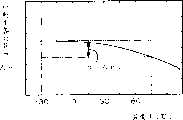
根据本发明,由于反射型显示装置通过照明装置被照明,因而可提高反射型显示装置的亮度,同时由于即使不点亮照明装置,也可进行利用了外光的显示,因而可降低消耗电力。尤其是,由于透过偏振光轴可变手段包含TN型液晶层,TN型液晶层的Δn·d处于0.7μm~1.7μm范围内,因而可降低由显示部形成的显示状态及镜状态的着色,同时可使显示明亮。此外由于Δn·d较小,因而显示图像的模糊也变小,视角范围也可得到某种程度的确保。According to the present invention, since the reflective display device is illuminated by the lighting device, the luminance of the reflective display device can be increased, and at the same time, the display using external light can be performed without turning on the lighting device, thereby reducing power consumption. In particular, since the transmission polarization axis variable means includes a TN-type liquid crystal layer, and the Δnd of the TN-type liquid crystal layer is in the range of 0.7 μm to 1.7 μm, it is possible to reduce the coloring of the display state and the mirror state formed by the display part. , making the display brighter at the same time. In addition, since Δn·d is small, the blurring of the displayed image is also reduced, and the viewing angle range can also be ensured to some extent.
在该场合下,上述TN型液晶层最好具有0.9μm~1.3μm范围内的Δn·d。通过TN型液晶层具有该范围内的Δn·d,可进一步降低着色,可进行更为明亮的显示。尤其是,由于镜状态下的着色被大大改善,因而可实现理想的镜面状态。In this case, the TN-type liquid crystal layer preferably has Δn·d in the range of 0.9 μm to 1.3 μm. When the TN-type liquid crystal layer has Δn·d within this range, coloring can be further reduced and brighter display can be performed. In particular, since the coloring in the mirror state is greatly improved, an ideal mirror state can be realized.
其次,本发明的显示装置的特征在于具有:显示部,其为形成显示状态而射出光;及显示切换部,其以与上述显示部的至少一部分重叠的方式配置在上述显示部的观察侧,上述显示切换部包含从上述显示部向观察侧依次配置的第1偏振光片、液晶面板、及第2偏振光片,上述第1偏振光片在使第1偏振光透过的同时,使具有与上述第1偏振光的偏振光轴交叉的偏振光轴的第2偏振光反射,上述液晶面板构成为可切换使上述第1偏振光变为上述第2偏振光而透过的状态与使入射的光的偏振光轴不发生变化而透过的状态,上述第2偏振光片使上述第1偏振光与上述第2偏振光中的任意一方透过,对另一方进行吸收或反射,上述显示部为形成上述显示状态而射出上述第1偏振光,上述液晶面板包含TN型液晶层、用于对上述TN型液晶层在厚度方向施加电场的电压施加装置,上述TN型液晶层具有0.50μm~0.65μm范围内的Δn·d,其中,Δn表示液晶的折射率各向异性,d表示液晶层的厚度,Δn·d表示光相位差。Next, the display device of the present invention is characterized by comprising: a display unit that emits light to form a display state; and a display switching unit that is disposed on the viewing side of the display unit so as to overlap at least a part of the display unit, The display switching unit includes a first polarizing plate, a liquid crystal panel, and a second polarizing plate that are sequentially arranged from the display unit to the observation side, and the first polarizing plate transmits the first polarized light while transmitting Reflecting the second polarized light of the polarized light axis crossing the polarized light axis of the first polarized light, the liquid crystal panel is configured to be switchable between a state in which the first polarized light is transmitted as the second polarized light and a state in which the incident light is transmitted. The polarization axis of the light is transmitted without changing, the second polarizer transmits either one of the first polarized light and the second polarized light, and absorbs or reflects the other, and the display The part emits the above-mentioned first polarized light to form the above-mentioned display state, the above-mentioned liquid crystal panel includes a TN-type liquid crystal layer, and a voltage applying device for applying an electric field to the above-mentioned TN-type liquid crystal layer in the thickness direction, and the above-mentioned TN-type liquid crystal layer has a thickness of 0.50 μm~ Δn·d in the range of 0.65 μm, where Δn represents the refractive index anisotropy of the liquid crystal, d represents the thickness of the liquid crystal layer, and Δn·d represents the optical phase difference.
根据本发明,由于反射型显示装置通过照明装置被照明,因而可提高反射型显示装置的亮度,同时由于即使不点亮照明装置,也可进行利用了外光的显示,因而可降低消耗电力。尤其是,由于透过偏振光轴可变手段包含TN型液晶层,TN型液晶层的Δn·d处于0.50μm~0.65μm范围内,在显示状态及镜状态可得到广阔的视角。According to the present invention, since the reflective display device is illuminated by the lighting device, the luminance of the reflective display device can be increased, and at the same time, the display using external light can be performed without turning on the lighting device, thereby reducing power consumption. In particular, since the transmission polarization axis variable means includes a TN-type liquid crystal layer, and the Δn·d of the TN-type liquid crystal layer is in the range of 0.50 μm to 0.65 μm, wide viewing angles can be obtained in the display state and the mirror state.
此外本发明的显示装置的特征在于具有:显示部,其为形成显示状态而射出光;及显示切换部,其以与上述显示部的至少一部分重叠的方式配置在上述显示部的观察侧,上述显示切换部包含从上述显示部向观察侧依次配置的第1偏振光片、液晶面板、及第2偏振光片,上述第1偏振光片在使第1偏振光透过的同时,使具有与上述第1偏振光的偏振光轴交叉的偏振光轴的第2偏振光反射,上述液晶面板构成为可切换使上述第1偏振光变为上述第2偏振光而透过的状态与使入射的光的偏振光轴不发生变化而透过的状态,上述第2偏振光片使上述第1偏振光与上述第2偏振光中的任意一方透过,对另一方进行吸收或反射,上述显示部包含显示用液晶面板,并为形成上述显示状态而射出上述第1偏振光,当将上述液晶面板的折射率各向异性设为Δnm、将上述液晶面板对波长λ=450nm的光的折射率各向异性设为Δnm1、将上述液晶面板对波长λ=590nm的光的折射率各向异性设时Δnm2,表示上述液晶面板的折射率各向异性的波长分散的αm=Δnm1/Δnm2,与当将上述显示用液晶面板的折射率各向异性设为Δnd、将上述显示用液晶面板对波长λ=450nm的光的折射率各向异性设为Δnd1、将上述显示用液晶面板对波长λ=590nm的光的折射率各向异性设为Δnd2时,表示上述显示用液晶面板的折射率各向异性的波长分散的
根据本发明,由于反射型显示装置通过照明装置被照明,因而可提高反射型显示装置的亮度,同时由于即使不点亮照明装置,也可进行利用了外光的显示,因而可降低消耗电力。尤其是,由于显示切换部的透过偏振光轴可变手段的波长分散针对显示部的显示用透过偏振光轴可变手段的折射率各向异性的波长分散之比处于0.9~1.1范围内,有关显示部与显示切换部之间的折射率各向异性的波长分散特性的差异被降低,因而可抑制基于设置了显示切换部的显示亮度的降低,同时可降低显示状态的着色。According to the present invention, since the reflective display device is illuminated by the lighting device, the luminance of the reflective display device can be increased, and at the same time, the display using external light can be performed without turning on the lighting device, thereby reducing power consumption. In particular, since the ratio of the wavelength dispersion of the transmission polarization axis variable means of the display switching part to the wavelength dispersion of the refractive index anisotropy of the display transmission polarization axis variable means of the display part is in the range of 0.9 to 1.1 Since the difference in wavelength dispersion characteristics related to the refractive index anisotropy between the display unit and the display switching unit is reduced, it is possible to suppress a decrease in display luminance due to the provision of the display switching unit and to reduce coloring of the display state.
此外本发明的显示装置的特征在于具有:显示部,其为形成显示状态而射出光;及显示切换部,其以与上述显示部的至少一部分重叠的方式配置在上述显示部的观察侧,上述显示切换部包含从上述显示部向观察侧依次配置的第1偏振光片、液晶面板、及第2偏振光片,上述第1偏振光片在使第1偏振光透过的同时,使具有与上述第1偏振光的偏振光轴交叉的偏振光轴的第2偏振光反射,上述液晶面板构成为可切换使上述第1偏振光变为上述第2偏振光而透过的状态与使入射的光的偏振光轴不发生变化而透过的状态,上述第2偏振光片使上述第1偏振光与上述第2偏振光中的任意一方透过,对另一方进行吸收或反射,上述显示部为形成上述显示状态而射出上述第1偏振光,上述液晶面板在可视光区域中的折射率各向异性Δnm,相对于在25℃的上述折射率各向异性Δnm的值,在-20~60℃范围内的上述折射率各向异性Δnm的值示出±8%以下的变动幅度。In addition, the display device of the present invention is characterized by having: a display unit that emits light to form a display state; The display switching unit includes a first polarizer, a liquid crystal panel, and a second polarizer arranged in order from the display unit toward the observation side, and the first polarizer transmits the first polarized light while transmitting The second polarized light whose polarization axis intersects the first polarized light is reflected, and the liquid crystal panel is configured to switch between a state in which the first polarized light is transmitted as the second polarized light and an incident state. In a state where the light is transmitted without changing its polarization axis, the second polarizer transmits either one of the first polarized light and the second polarized light, and absorbs or reflects the other, and the display unit The above-mentioned first polarized light is emitted toform the above-mentioned display state, and the refractive index anisotropy Δnm of the above-mentioned liquid crystal panel in the visible light region is - The value of the above-mentioned refractive index anisotropy Δnm in the range of 20 to 60° C. shows a fluctuation range of ±8% or less.
根据本发明,由于反射型显示装置通过照明装置被照明,因而可提高反射型显示装置的亮度,同时由于即使不点亮照明装置,也可进行利用了外光的显示,因而可降低消耗电力。尤其是,当Δnm的变化量超过8%后,色调、对比度等显示特性急剧变差,但由于变动幅度相对25℃的值在-20~60℃的范围内为±8%以下,可使显示切换部的透过率稳定,可抑制基于温度变化的透过率的降低。尤其是为维持显示特性,最好为±5%以下。According to the present invention, since the reflective display device is illuminated by the lighting device, the luminance of the reflective display device can be increased, and at the same time, the display using external light can be performed without turning on the lighting device, thereby reducing power consumption. In particular, when the variation of Δnm exceeds 8%, the display characteristics such as hue and contrast deteriorate rapidly, but since the range of variation relative to the value at 25°C is ±8% or less in the range of -20 to 60°C, it can be used The transmittance of the display switching portion is stabilized, and a decrease in transmittance due to temperature changes can be suppressed. In particular, in order to maintain display characteristics, it is preferably ±5% or less.
在上述各发明中,上述第2偏振光选择手段最好是使上述一方透过,对上述另一方吸收的吸收型偏振光选择手段。这样,由于可以降低显示状态下第2偏振光单元的表面反射,因而可进一步提高显示状态的显示图像质量。In each of the above inventions, it is preferable that the second polarization selection means is an absorption type polarization selection means which transmits the one and absorbs the other. In this way, since the surface reflection of the second polarizing unit in the display state can be reduced, the display image quality in the display state can be further improved.
在本发明中,上述显示部与上述显示切换部最好被光学接合。In the present invention, it is preferable that the display unit and the display switching unit are optically joined together.
在该场合下,上述显示部与上述显示切换部最好通过由粘合剂或接合剂组成的接合层被光学接合。In this case, it is preferable that the display portion and the display switching portion are optically bonded via a bonding layer composed of an adhesive or an adhesive.
此外上述接合层的折射率最好处于1.30~1.50的范围内。Moreover, it is preferable that the refractive index of the said bonding layer exists in the range of 1.30-1.50.
此外上述接合层最好是凝胶状物质。In addition, the above-mentioned bonding layer is preferably a gel-like substance.
在本发明中,最好在上述显示切换部的表里两面形成反射防止膜。在该场合下,在上述显示部的上述显示切换部侧的表面最好也形成反射防止膜。In the present invention, it is preferable to form an anti-reflection film on both front and rear surfaces of the display switching portion. In this case, it is also preferable to form an anti-reflection film on the surface of the display unit on the side of the display switching unit.
此外在上述显示切换部中,最好设有全面构成了单一像素的全面像素区域、小于上述全面像素区域的所定形状的多个像素被排列的像素排列区域。Furthermore, in the above-mentioned display switching unit, it is preferable to provide an entire pixel area in which a single pixel is formed over the entire area, and a pixel arrangement area in which a plurality of pixels having a predetermined shape smaller than the entire pixel area are arranged.
此外在上述显示切换部中,最好设有配置上述第1偏振光选择手段的区域、取代上述第1偏振光选择手段而配置了在使上述第1偏振光透过的同时,吸收上述第2偏振光的第3偏振光选择手段的区域。In addition, in the above-mentioned display switching part, it is preferable to provide a region for disposing the above-mentioned first polarized light selecting means, instead of the above-mentioned first polarized light selecting means, a region for transmitting the above-mentioned first polarized light and absorbing the above-mentioned second polarized light is preferably provided. The area of the third polarized light selection means of polarized light.
此外在上述显示部中,最好设有与上述显示切换部不重叠的区域。Furthermore, in the display unit, it is preferable to provide a region that does not overlap with the display switching unit.
此外在上述显示切换部中,最好设有与上述显示部不平面重叠的区域,在该区域中,排列有所定形状的多个像素。In addition, in the display switching unit, it is preferable to provide a region that does not planarly overlap with the display unit, and in this region, a plurality of pixels having a predetermined shape are arranged.
此外本发明的显示装置的特征在于具有:显示部,其为形成显示状态而射出光;及显示切换部,其以与上述显示部的至少一部分重叠的方式配置在上述显示部的观察侧,上述显示切换部包含从上述显示部向观察侧依次配置的第1偏振光片、液晶面板、及第2偏振光片,上述第1偏振光片在使第1偏振光透过的同时,使具有与上述第1偏振光的偏振光轴交叉的偏振光轴的第2偏振光反射,上述液晶面板构成为可切换使上述第1偏振光变为上述第2偏振光而透过的状态与使入射的光的偏振光轴不发生变化而透过的状态,上述第2偏振光片使上述第1偏振光与上述第2偏振光中的任意一方透过,对另一方进行吸收或反射,上述显示部为形成上述显示状态而射出第3偏振光,上述显示部包含配置于上述显示切换部侧的照明装置、及配置于该照明装置的背面侧的反射型显示装置,上述照明装置在向上述反射型显示装置照射光的同时使从上述反射型显示装置入射的光透过,在上述显示部与上述显示切换部之间,配置有将上述第3偏振光转换为上述第1偏振光的偏振光转换装置。In addition, the display device of the present invention is characterized by having: a display unit that emits light to form a display state; The display switching unit includes a first polarizer, a liquid crystal panel, and a second polarizer arranged in order from the display unit toward the observation side, and the first polarizer transmits the first polarized light while transmitting The second polarized light whose polarization axis intersects the first polarized light is reflected, and the liquid crystal panel is configured to switch between a state in which the first polarized light is transmitted as the second polarized light and an incident state. In a state where the light is transmitted without changing its polarization axis, the second polarizer transmits either one of the first polarized light and the second polarized light, and absorbs or reflects the other, and the display unit In order to form the above-mentioned display state and emit third polarized light, the above-mentioned display unit includes an illumination device arranged on the side of the above-mentioned display switching part, and a reflective display device arranged on the back side of the illuminating device. The display device transmits light incident from the reflective display device while irradiating light, and a polarization converter for converting the third polarized light into the first polarized light is disposed between the display unit and the display switching unit. device.
在本发明中,上述偏振光片最好是相位差片。在该场合下,上述相位差片最好是1/2波长片。In the present invention, the polarizing film is preferably a retardation film. In this case, the retardation film is preferably a 1/2 wavelength film.
其次,本发明的电子设备具备上述任一中记载的显示装置、控制上述显示部的显示控制单元、控制上述显示切换部的显示切换控制单元。由于该显示装置如上所述可对显示状态与镜状态进行切换,因而可将显示画面作为镜使用,所以最好作为便携电话或便携型信息终端等便携型电子设备来构成。Next, an electronic device of the present invention includes the display device described in any one of the above, a display control unit that controls the display unit, and a display switching control unit that controls the display switching unit. Since the display device can switch between the display state and the mirror state as described above, the display screen can be used as a mirror, so it is preferably configured as a portable electronic device such as a mobile phone or a portable information terminal.
附图说明Description of drawings
图1是示意性表示表示本发明涉及的基本构成例的构成例1的显示装置的概略结构图。FIG. 1 is a schematic configuration diagram schematically showing a display device according to Configuration Example 1, which is a basic configuration example according to the present invention.
图2是示意性表示表示本发明涉及的基本构成例的构成例2的显示装置的概略结构图。FIG. 2 is a schematic configuration diagram schematically showing a display device of configuration example 2 showing a basic configuration example according to the present invention.
图3是示意性表示表示本发明涉及的基本构成例的构成例3的显示装置的概略结构图。3 is a schematic configuration diagram schematically showing a display device of Configuration Example 3, which is a basic configuration example according to the present invention.
图4是示意性表示表示本发明涉及的基本构成例的构成例4的显示装置的概略结构图。4 is a schematic configuration diagram schematically showing a display device of Configuration Example 4, which is a basic configuration example according to the present invention.
图5是示意性表示本发明涉及的实施方式1构成的概略断面图。Fig. 5 is a schematic cross-sectional view schematically showing the configuration of Embodiment 1 according to the present invention.
图6是示意性表示本发明涉及的实施方式2构成的概略断面图。Fig. 6 is a schematic cross-sectional view schematically showing the configuration of Embodiment 2 according to the present invention.
图7是示意性表示本发明涉及的实施方式3构成的概略断面图。7 is a schematic cross-sectional view schematically showing the configuration of Embodiment 3 according to the present invention.
图8是示意性表示本发明涉及的实施方式4构成的概略断面图。Fig. 8 is a schematic cross-sectional view schematically showing the configuration of Embodiment 4 according to the present invention.
图9是示意性表示本发明涉及的实施方式5构成的概略断面图(a)及概略平面图(b)。9 is a schematic sectional view (a) and a schematic plan view (b) schematically showing the configuration of Embodiment 5 according to the present invention.
图10是示意性表示本发明涉及的实施方式6构成的概略断面图(a)及概略平面图(b)。10 is a schematic sectional view (a) and a schematic plan view (b) schematically showing the configuration of Embodiment 6 according to the present invention.
图11是示意性表示具有基本构成的显示装置的概略断面图(a)及示意性表示本发明涉及的实施方式7构成的概略断面图(b)。11 is a schematic cross-sectional view (a) schematically showing a display device having a basic configuration and a schematic cross-sectional view (b) schematically showing a configuration of Embodiment 7 according to the present invention.
图12是示意性表示本发明涉及的实施方式8构成的概略断面图。Fig. 12 is a schematic cross-sectional view schematically showing the configuration of Embodiment 8 according to the present invention.
图13是表示波长与液晶的折射率各向异性的关系的曲线图。Fig. 13 is a graph showing the relationship between wavelength and refractive index anisotropy of liquid crystals.
图14是表示温度与液晶的折射率各向异性的关系的曲线图。Fig. 14 is a graph showing the relationship between temperature and refractive index anisotropy of liquid crystals.
图15是示意性表示包含实施方式8的前灯的构成例的概略断面图。15 is a schematic cross-sectional view schematically showing a configuration example including a headlight according to Embodiment 8. FIG.
图16是示意性表示具备了显示装置的电子设备中的显示控制系统的结构的概略构成框图。16 is a schematic configuration block diagram schematically showing the configuration of a display control system in an electronic device including a display device.
图17是示意性表示电子设备(便携电话)的外观的概略斜视图。Fig. 17 is a schematic perspective view schematically showing the appearance of an electronic device (mobile phone).
图18是示意性表示不同的电子设备(便携电话)的外观的概略斜视图。Fig. 18 is a schematic perspective view schematically showing the appearance of a different electronic device (mobile phone).
具体实施方式Detailed ways
接下来,参照附图对本发明涉及的显示装置及电子设备的实施方式作以详细说明。Next, embodiments of the display device and electronic equipment according to the present invention will be described in detail with reference to the drawings.
[实施方式的基本构成例][Basic Configuration Example of Embodiment]
首先,参照图1至图4对本发明涉及的各实施方式中可采用的基本构成例作以说明。First, examples of basic configurations that can be employed in each embodiment of the present invention will be described with reference to FIGS. 1 to 4 .
(构成例1)图1所示的显示装置100按照显示部110与显示切换部120平面重叠的原则配置。显示部110与显示切换部120的重叠状态可以是互相至少有一部分重叠。(Structural Example 1) The
这里,显示部110虽然可以具有在显示切换部120侧可形成所定的图像等显示形式的结构(比如,EL(场致发光)元件、PDP(等离子体显示面板)装置、FED(场致发射装置)等各种显示单元),但在本实施方式的场合下,采用作为液晶显示装置来构成的部件。Here, although the display unit 110 may have a structure capable of forming a display format such as a predetermined image on the side of the display switching unit 120 (for example, an EL (Electroluminescence) element, a PDP (Plasma Display Panel) device, a FED (Field Emission Device) ) and other various display units), but in the case of this embodiment, a member configured as a liquid crystal display device is used.
作为显示部110的液晶方式,最好是TN(Twisted Nematic)方式、STN(Super Twisted Nematic)方式、ECB(ElectricallyControlled Birefringence)方式等。由于基于这些液晶方式的显示单元按照采用偏振光片实现显示形式的原则来构成,因而可在较低的驱动电压下获得高显示质量,尤其最好用于搭载于便携型电子设备的场合。As the liquid crystal method of the display unit 110, TN (Twisted Nematic) method, STN (Super Twisted Nematic) method, ECB (Electrically Controlled Birefringence) method, etc. are preferable. Since the display units based on these liquid crystals are constructed based on the principle of using polarizers to realize the display form, high display quality can be obtained at a relatively low driving voltage, and are especially suitable for use in portable electronic devices.
此外作为显示部110的驱动方式,可以是采用了TFT(Thin FilmTransistor)及TFD(Thin Film Diode)等有源元件的有源矩阵驱动等的有源驱动方式与不采用上述有源元件的单纯驱动或复合驱动等的无源驱动方式的任意一种。In addition, as the driving method of the display unit 110, active driving methods such as active matrix driving using active elements such as TFT (Thin Film Transistor) and TFD (Thin Film Diode) and simple driving without using the above-mentioned active elements can be used. Either of passive driving methods such as composite driving or the like.
此外作为显示部110的面板结构,可以是反射型面板、反射半透过型面板、透过型面板的任意一种。在反射型面板的场合下,在光学要素的反观察侧构成反射面。在反射半透过型面板的场合下,可举出反射面由半反射镜等反射半透过材料构成的情况及在反射面上按每个像素或扇区设置开口的情况等。In addition, the panel structure of the display unit 110 may be any of a reflective panel, a transflective panel, and a transmissive panel. In the case of a reflective panel, the reflective surface is formed on the opposite viewing side of the optical element. In the case of a transflective panel, examples include a case where the reflective surface is made of a semitransmissive material such as a half mirror, and a case where openings are provided for each pixel or sector on the reflective surface.
对本实施方式的显示部110的结构作更为具体的说明,比如如图1所示,在显示部110中,从显示切换部120侧依次配置偏振光片111、相位差片112、液晶面板113、偏振光片114、背照灯115。此外在将显示部110作为反射型液晶显示装置来构成的场合下,也可以取代背照灯115,配置反射片。此外也可以将该反射片配置到液晶面板113的内部。The structure of the display unit 110 of the present embodiment will be described more specifically. For example, as shown in FIG. , polarizer 114, backlight 115. In addition, when the display unit 110 is configured as a reflective liquid crystal display device, a reflective sheet may be disposed instead of the backlight 115 . Alternatively, the reflective sheet may be arranged inside the liquid crystal panel 113 .
液晶面板113具有在2个基片113a与113b之间裹夹了液晶层113c的结构。2个基片113a与113b由密封材料等按照具有所定间隔(比如3~10μm)的原则被贴合。此外按照在基片113a与113b的内面形成未图示的电极,通过这些电极,可在液晶层113c中施加电场的原则来构成。在液晶面板113的内部,形成具有针对可视光的半透过性的反射层及按每个像素具备了小开口的反射层等,由此可构成反射半透过型的液晶显示装置。The liquid crystal panel 113 has a structure in which a liquid crystal layer 113c is sandwiched between two substrates 113a and 113b. The two substrates 113a and 113b are bonded by a sealing material or the like with a predetermined interval (for example, 3 to 10 μm). In addition, it is constructed on the principle that electrodes (not shown) are formed on the inner surfaces of the substrates 113a and 113b, and an electric field can be applied to the liquid crystal layer 113c through these electrodes. Inside the liquid crystal panel 113 , a reflective layer having transflectivity to visible light, a reflective layer having small openings for each pixel, and the like are formed, thereby constituting a transflective liquid crystal display device.
偏振光片111、114按液晶装置的构成上必要的配置(比如正交尼科尔配置)设定。作为偏振光片111、114,采用使具有与其偏振光透过轴平行的振动面的偏振光成分透过,对在与偏振光透过轴交叉(最好是正交)的方向上具有平行的振动面的偏振光成分进行吸收的众所周知的吸收型偏振光片。The polarizers 111 and 114 are set in an arrangement (for example, a crossed Nicol arrangement) necessary for the configuration of the liquid crystal device. As the polarizing plates 111, 114, the polarized light components having the vibration plane parallel to the polarized light transmission axis are adopted to transmit, and the polarized light plates have parallel polarized light components in the direction crossing (preferably orthogonal) to the polarized light transmission axis. A well-known absorbing polarizer that absorbs the polarized light component of the vibrating plane.
背照灯115只要是可从背后对液晶面板113以几乎均一的照度进行照明的灯都可以。比如,可以举出包含导光片、配置于该导光片端面部的光源的端面发光型背照灯及包含导光片、配置于该导光片背面的光源的背面发光型背照灯等。The backlight 115 may be any lamp as long as it can illuminate the liquid crystal panel 113 from behind with a substantially uniform illuminance. For example, an end-emission backlight including a light guide sheet and a light source arranged on the end surface of the light guide sheet, and a back-emission backlight including a light guide sheet and a light source arranged on the back surface of the light guide sheet may be mentioned.
另一方面,显示切换部120包含从上述显示部110向观察侧依次配置的反射偏振光片121、液晶面板122、偏振光片123。反射偏振光片121使具有与其透过偏振光轴平行的振动面的偏振光成分透过,使在与透过偏振光轴交叉(最好是正交)的方向上具有平行的振动面的偏振光成分反射。作为反射偏振光片,可以采用在国际专利申请公开WO95/27919号中记载的层积了多种互相不同的双折射性高分子薄膜的层积体或在胆甾醇液晶的表里配置了1/4波长片的偏振光片等。作为上述层积体,有由3M公司提供的品名为DBEF的层积膜。On the other hand, the display switching unit 120 includes a reflective polarizer 121 , a liquid crystal panel 122 , and a polarizer 123 arranged in this order from the display unit 110 toward the observation side. The reflective polarizer 121 transmits the polarized light component having a vibration plane parallel to the transmission polarization axis, and makes the polarization component having a parallel vibration plane in a direction crossing (preferably orthogonal) to the transmission polarization axis. The light component reflects. As the reflective polarizer, it is possible to use a laminate in which multiple birefringent polymer films different from each other are laminated as described in International Patent Application Publication WO95/27919, or a 1/2 layer is arranged on the front and back of the cholesteric liquid crystal. 4-wavelength polarizer, etc. As the above-mentioned laminate, there is a laminated film provided by 3M Corporation under the product name DBEF.
液晶面板122在2个基片122a与122b之间裹夹了液晶层122c。在基片122a、122b的内面分别形成未图示的透明电极,按照通过这些透明电极,可在液晶层122c中施加所定电场的原则来构成。在该液晶面板122的场合下,在液晶层122c的两侧,可以分别逐一设置按照几乎全面覆盖有效显示区内的原则来构成的一体的上述透明电极。但也可以按照上述透明电极在液晶层122c两侧分别形成多个,互相独立地供给电位的原则来构成。In the liquid crystal panel 122, a liquid crystal layer 122c is sandwiched between two substrates 122a and 122b. Transparent electrodes (not shown) are formed on the inner surfaces of the substrates 122a and 122b, respectively, and a predetermined electric field can be applied to the liquid crystal layer 122c through these transparent electrodes. In the case of the liquid crystal panel 122, on both sides of the liquid crystal layer 122c, the above-mentioned integral transparent electrodes configured to cover almost the entire area of the effective display area can be provided one by one. However, a plurality of transparent electrodes may be formed on both sides of the liquid crystal layer 122c to supply potentials independently of each other.
偏振光片123比如与上述同样,是使具有与其透过偏振光轴平行的振动面的偏振光成分透过,对在与透过偏振光轴交叉(最好是正交)的方向上具有平行的振动面的偏振光成分进行吸收的众所周知的吸收型偏振光片。但也可采用与上述反射偏振光片121同样构成的反射偏振光片。The polarizing plate 123, for example, is the same as above, and transmits the polarized light component having a vibration plane parallel to the transmission polarization axis, and has a parallel to the direction crossing (preferably orthogonal) to the transmission polarization axis. A well-known absorption polarizer that absorbs the polarized light component of the vibration plane. However, a reflective polarizer having the same configuration as the aforementioned reflective polarizer 121 may also be used.
作为液晶面板122的形式,最好是TN型面板结构与STN型面板结构的任意一种。此外作为构成面板结构的基片,可以是以下的任意一种:采用了玻璃(包含石英)的基片、采用了树脂(塑料)的基片、在一面采用玻璃,在另一面采用了树脂的基片。通过在基片上采用树脂,可实现薄型化,可提高耐冲击性。但是在基片上采用树脂的场合下,难以得到液晶面板122的平坦性,因而如后所述,最好对显示部110进行光学接合。比如,通过采用具有适当的折射率的透明树脂接合剂,可以达到使液晶面板122通过实质上不受光学影响的接合层被贴附到了显示部110的状态。As the form of the liquid crystal panel 122, any one of a TN type panel structure and an STN type panel structure is preferable. In addition, as the substrate constituting the panel structure, any of the following may be used: a substrate using glass (including quartz), a substrate using resin (plastic), and a substrate using glass on one side and resin on the other side. substrate. By using resin on the substrate, it is possible to achieve thinning and improve impact resistance. However, when a resin is used for the substrate, it is difficult to obtain flatness of the liquid crystal panel 122, so it is preferable to optically bond the display portion 110 as described later. For example, by using a transparent resin adhesive having an appropriate refractive index, it is possible to achieve a state where the liquid crystal panel 122 is attached to the display unit 110 via an adhesive layer that is substantially not affected by optics.
上述显示切换部120的反射偏振光片121的透过偏振光轴与上述显示部110的偏振光片111的透过偏振光轴最好按照朝向基本相互一致的方向的原则来配置。但反射偏振光片121的透过偏振光轴与偏振光片111的透过偏振光轴即使不一致,如果两个透过偏振光轴的交叉角处于15度以下,也可具有后述的显示切换功能。The transmission polarization axis of the reflective polarizer 121 of the display switching unit 120 and the transmission polarization axis of the polarizer 111 of the display unit 110 are preferably arranged to be oriented in substantially the same direction. However, even if the transmission polarization axis of the reflective polarizer 121 is inconsistent with the transmission polarization axis of the polarizer 111, if the intersection angle of the two transmission polarization axes is below 15 degrees, the display switching described later can also be provided. Function.
在本实施方式的显示装置100中,通过对施加到显示切换部120的液晶面板122的液晶层122c的电场强度进行控制,或对有无电场施加进行切换,可以使显示切换部120达到透过状态,或通过显示切换部120使外光反射。In the
作为一例,对显示切换部120的液晶面板122是TN型液晶面板,按照反射偏振光片121的透过偏振光轴与偏振光片123的透过偏振光轴正交的原则来配置的场合作以说明。在该场合下,在液晶层122c中未施加电场时,液晶层122c内的向列液晶呈现90度的扭转状态,基本具有90度的旋光性。因此,外光入射到显示切换部120后,通过从偏振光片123中通过,透过光成为具有与偏振光片123的透过偏振光轴平行的振动面的直线偏振光,通过该直线偏振光从液晶面板122中通过,被转换为具有与偏振光片123的透过偏振光轴正交的振动面的直线偏振光。该直线偏振光由于具有与反射偏振光片121的透过偏振光轴平行的振动面,因而透过反射偏振光片121,入射到显示部110。入射到显示部110的光透过偏振光片111,在显示部110构成反射型显示装置(比如反射型或反射半透过型的液晶显示装置)的场合下,成为构成显示部110的显示图像的光的至少一部分。As an example, the liquid crystal panel 122 of the display switching part 120 is a TN type liquid crystal panel, and the occasion that is arranged according to the principle that the transmission polarization axis of the reflective polarizer 121 is perpendicular to the transmission polarization axis of the polarizer 123 is to illustrate. In this case, when no electric field is applied to the liquid crystal layer 122c, the nematic liquid crystal in the liquid crystal layer 122c assumes a 90-degree twisted state, and basically has 90-degree optical rotation. Therefore, after external light enters the display switching unit 120, it passes through the polarizing plate 123, and the transmitted light becomes linearly polarized light having a vibration plane parallel to the transmission polarization axis of the polarizing plate 123. The light passes through the liquid crystal panel 122 and is converted into linearly polarized light having a vibration plane perpendicular to the transmission polarization axis of the polarizer 123 . Since the linearly polarized light has a vibration plane parallel to the transmission polarization axis of the reflective polarizer 121 , it passes through the reflective polarizer 121 and enters the display unit 110 . The light incident on the display unit 110 passes through the polarizer 111, and when the display unit 110 constitutes a reflective display device (such as a reflective or reflective transflective liquid crystal display device), it becomes a display image constituting the display unit 110. at least part of the light.
另一方面,从显示部110射出的光(即构成显示部110的显示图像的光)通过显示部120的偏振光片111,成为具有与偏振光片111的透过偏振光轴平行的振动面的直线偏振光。因此,该直线偏振光透过反射偏振光片121,入射到液晶面板122。由于该直线偏振光的振动面通过从液晶面板122中通过而旋转90度,因而在从液晶面板122中通过后透过偏振光片123,射出到观察侧。因此,由显示部110构成的显示图像按原样透过显示切换部120被视见(显示状态)。On the other hand, the light emitted from the display unit 110 (that is, the light constituting the displayed image of the display unit 110 ) passes through the polarizing plate 111 of the display unit 120 , and has a vibration plane parallel to the transmission polarization axis of the polarizing plate 111 . linearly polarized light. Therefore, the linearly polarized light passes through the reflective polarizer 121 and enters the liquid crystal panel 122 . Since the vibration plane of this linearly polarized light is rotated by 90 degrees by passing through the liquid crystal panel 122 , after passing through the liquid crystal panel 122 , it passes through the polarizing plate 123 and is emitted to the observation side. Therefore, the display image constituted by the display unit 110 is seen through the display switching unit 120 as it is (display state).
其次,由于在液晶面板122中在液晶层122c上施加了所定的阈值以上的电场的场合下,液晶层122c内的液晶扭转状态消失,因而液晶面板122失去针对在其光轴方向上透过的光的旋光性。因此在该场合下,由于外光入射到显示切换部120后,与上述同样,透过偏振光片123所生成的直线偏振光不改变振动面地从液晶面板122中通过,因而通过反射偏振光片121反射。由于该反射光即使再次透过液晶面板122其振动面也不变化,因而按原样透过偏振光片123并被视见。Next, when an electric field above a predetermined threshold value is applied to the liquid crystal layer 122c in the liquid crystal panel 122, the twisted state of the liquid crystal in the liquid crystal layer 122c disappears, and the liquid crystal panel 122 loses the resistance to transmission in the direction of its optical axis. Optical rotation of light. Therefore, in this case, after external light enters the display switching unit 120, the linearly polarized light generated by the polarizer 123 passes through the liquid crystal panel 122 without changing the vibration plane as described above. Sheet 121 reflects. Since the vibration plane of the reflected light does not change even when it passes through the liquid crystal panel 122 again, it passes through the polarizing plate 123 and is seen as it is.
此外从显示部110射出的光虽然与上述同样是具有与偏振光片111的透过偏振光轴平行的振动面的直线偏振光,但由于按原样透过显示切换部120的反射偏振光片121,不改变振动面而透过液晶面板122,因而由偏振光片123吸收。因此显示部110的显示图像基本上不能被从外部视见。In addition, although the light emitted from the display unit 110 is linearly polarized light having a vibration plane parallel to the transmission polarization axis of the polarizer 111 as described above, since it passes through the reflective polarizer 121 of the display switching unit 120 as it is, , transmits through the liquid crystal panel 122 without changing the vibration plane, and thus is absorbed by the polarizer 123 . Therefore, the display image of the display unit 110 is basically invisible from the outside.
如上所述,在显示切换部120中,液晶面板122成为电场施加状态,由此外光的一部分被反射,从显示部110入射的光由偏振光片123吸收,不能被从外部视见,因而显示画面成为镜面状态(镜状态)。As described above, in the display switching unit 120, the liquid crystal panel 122 is in an electric field application state, whereby part of the external light is reflected, and the light incident from the display unit 110 is absorbed by the polarizer 123, and cannot be seen from the outside, so the display The screen becomes a mirror state (mirror state).
(构成例2)接下来,对本发明涉及的构成例2的显示装置200作以说明。图2是示意性表示显示装置200的概略构成的概略构成图。(Configuration Example 2) Next, a
显示装置200与实施方式1同样具有显示部210和显示切换部220。显示部210与实施方式1同样,具有相位差片221、液晶面板213(具有基片213a,213b及液晶层213c。)、偏振光片214、背照灯215。在作为反射型液晶显示装置来构成的场合下,不需要背照灯215这一点也与实施方式1同样。在本实施方式下,在显示部210中,在液晶面板213的观察侧(显示切换部220侧)不设置偏振光片这一点与实施方式1不同。The
另一方面,在显示切换部220中,从显示部210侧向观察侧配置有与实施方式1同样的反射偏振光片221、液晶面板222(具有基片222a,222b及液晶层222c。)、偏振光片223。由于该显示切换部220的各构成要素的关系及各构成要素的内容与实施方式1完全相同,因而省略说明。On the other hand, in the
在本实施方式中,虽然省略了显示部210的观察侧的偏振光片,但该偏振光片的功能由显示切换部220的反射偏振光片221实现。即,由于该反射偏振光片221使具有与其透过偏振光轴平行的振动面的偏振光成分透过,对具有与透过偏振光轴交叉(最好是正交)的振动面的偏振光成分进行反射,因而如果反射偏振光片221的透过偏振光轴按照朝向与应配置于显示部210的观察侧的偏振光片的透过偏振光轴几乎一致的方向的原则来配置,则基本上可以得到与实施方式1同样的效果。因此通过显示切换部220的反射偏振光片221来获得显示部210的显示状态这一点可与实施方式1同样,与此同时,同样也可通过该反射偏振光片221来获得镜状态。In this embodiment, although the polarizer on the viewing side of the
(构成例3)接下来,参照图3对本发明涉及的实施方式3的显示装置300作以说明。该显示装置300与上述同样具有显示部310和显示切换部320。在本实施方式中,由于显示切换部320具有与上述各实施方式同样的反射偏振光片321、液晶面板322(具有基片322a,322b及液晶层322c。)及偏振光片323,因而省略这些说明。(Configuration Example 3) Next, a display device 300 according to Embodiment 3 of the present invention will be described with reference to FIG. 3 . This display device 300 includes a display unit 310 and a display switching unit 320 as described above. In this embodiment, since the display switching unit 320 has the reflective polarizer 321, the liquid crystal panel 322 (having the substrates 322a, 322b and the liquid crystal layer 322c), and the polarizer 323 similar to those in the above-mentioned embodiments, these are omitted. illustrate.
在本实施方式中,显示部310由反射半透过型液晶显示装置构成这一点与上述各实施方式不同。在显示部310中,包含从显示切换部320侧依次配置的偏振光片311、相位差片312、液晶面板313、相位差片316、偏振光片314及背照灯315。This embodiment differs from the above-described embodiments in that the display unit 310 is constituted by a transflective liquid crystal display device. The display unit 310 includes a polarizer 311 , a retardation film 312 , a liquid crystal panel 313 , a retardation film 316 , a polarizer 314 , and a backlight 315 arranged in this order from the display switching unit 320 side.
在液晶面板313中,设有由2个基片313a与313b裹夹的液晶层313c。此外在背照灯315侧的基片(即观察侧的相反侧的基片)313b的内面上形成有反射层313d。该反射层313d由铝、银或这些合金等的反射性材料所构成的薄膜来构成。在反射层313d中,按用于形成显示图像的多个像素的每一个分别设有开口部313e。这样,按照从观察侧向液晶面板313入射的光由反射层313d反射,同时从背照灯315入射的光透过开口部313e的原则来构成。In the liquid crystal panel 313, a liquid crystal layer 313c sandwiched by two substrates 313a and 313b is provided. Further, a reflective layer 313d is formed on the inner surface of the substrate 313b on the side of the backlight 315 (ie, the substrate on the side opposite to the viewing side). The reflective layer 313d is formed of a thin film made of a reflective material such as aluminum, silver, or an alloy thereof. In the reflective layer 313d, an opening 313e is provided for each of a plurality of pixels for forming a display image. In this manner, light incident on the liquid crystal panel 313 from the viewing side is reflected by the reflective layer 313d, and light incident from the backlight 315 is transmitted through the opening 313e.
在该显示装置300中,从观察侧(显示切换部320侧)入射的外光通过偏振光片311成为具有与其透过偏振光轴平行的振动面的直线偏振光,在从相位差片312中通过并入射到液晶面板313后,透过液晶层313c由反射层313d反射。该反射光再次透过液晶层313c,并从相位差片312中透过,入射到偏振光片311。入射到偏振光片311的光的偏振光状态根据液晶层313c的电压施加状态而变化,根据其变化状态,决定是透过偏振光片311还是由偏振光片311吸收。In this display device 300, external light incident from the observation side (display switching part 320 side) passes through the polarizer 311 and becomes linearly polarized light having a vibration plane parallel to the transmission polarization axis. After passing through and entering the liquid crystal panel 313, it passes through the liquid crystal layer 313c and is reflected by the reflective layer 313d. The reflected light passes through the liquid crystal layer 313 c again, passes through the retardation film 312 , and enters the polarizing film 311 . The polarization state of the light incident on the polarizer 311 changes according to the voltage application state of the liquid crystal layer 313c, and whether it is transmitted or absorbed by the polarizer 311 is determined according to the change state.
另一方面,从背照灯315放出的光通过偏振光片314,成为具有与该透过偏振光轴平行的振动面的直线偏振光,经过相位差片316从液晶面板313的上述开口部313e入射到液晶层313c内。通过了液晶层313c的光在通过了相位差片312后,入射到偏振光片311。On the other hand, the light emitted from the backlight 315 passes through the polarizer 314, becomes linearly polarized light having a vibration plane parallel to the transmission polarization axis, passes through the retardation film 316, and passes through the above-mentioned opening 313e of the liquid crystal panel 313. enters the liquid crystal layer 313c. The light passing through the liquid crystal layer 313 c is incident on the polarizer 311 after passing through the retardation film 312 .
入射到该偏振光片311的光的偏振光状态根据液晶层313c的电压施加状态而变化,根据其变化状态,决定是透过偏振光片311还是由偏振光片311吸收。The polarization state of the light incident on the polarizer 311 changes according to the voltage application state of the liquid crystal layer 313c, and whether it is transmitted through the polarizer 311 or absorbed by the polarizer 311 is determined according to the change state.
在本实施方式中同样,显示切换部320根据施加到液晶面板322内的液晶层322c的电压值或电压的有无,决定是成为透过状态还是成为反射状态。这样,在显示切换部320呈现透过状态时,由上述显示部310构成的显示图像被视见。该显示图像在周围明亮的场合下不借助背照灯315的帮助作为反射型显示来构成,在周围昏暗的场合下通过背照灯315的光作为透过型显示来构成。Also in this embodiment, the display switching unit 320 determines whether to be in a transmissive state or a reflective state based on the voltage value applied to the liquid crystal layer 322c in the liquid crystal panel 322 or the presence or absence of voltage. In this way, when the display switching unit 320 assumes the transparent state, the display image constituted by the display unit 310 is viewed. This display image is configured as a reflective display without the help of the backlight 315 when the surrounding is bright, and as a transmissive display by the light of the backlight 315 when the surrounding is dark.
(构成例4)接下来,参照图4对本发明涉及的实施方式4的显示装置400作以说明。在该显示装置400中,基本与上述各实施方式同样具有显示部410及显示切换部420。在该实施方式中,由于显示切换部420具有与上述各实施方式完全相同的反射偏振光片421、液晶面板422(具有基片422a,422b及液晶层422c。)及偏振光片423,因而省略这些说明。(Configuration Example 4) Next, a
此外显示部410具有与上述实施方式3完全相同的相位差片412、液晶面板413、相位差片416、偏振光片414及背照灯415。这样,与实施方式3同样在液晶面板413上设置基片413a、413b、液晶层413c、反射层413d及开口部413e。不过在该显示部410中,未设置在实施方式3中设置的观察侧(显示切换部420侧)的偏振光片这一点与上述不同。在该显示装置400中,按照显示切换部420的反射偏振光片421的透过偏振光轴朝向与应配置于显示部410的观察侧的偏振光片的透过偏振光轴一致的方向的原则来构成。In addition, the
在该实施方式中,在显示部410中虽然未配置观察侧的偏振光片,但该偏振光片的功能与实施方式2同样由显示切换部420中的反射偏振光片421完成,因而与上述同样可具有与实施方式3同样的作用效果。In this embodiment, although no polarizer on the viewing side is arranged in the
以上对可用于本发明涉及的实施方式的基本构成例作了说明,但上述构成例1至构成例4不过是一种例示,在实际中只要具有本申请发明的必须构成要素,不脱离其要旨,便可以进行各种构成变更。As mentioned above, the basic structural examples applicable to the embodiments of the present invention have been described, but the above-mentioned structural examples 1 to 4 are merely examples, and in practice, as long as they have the essential structural elements of the present invention, they will not deviate from the gist. , various configuration changes are possible.
[实施方式1][Embodiment 1]
以下参照图5对本发明涉及的实施方式1的显示装置作以说明。该实施方式1基于上述构成例1来构成,在图5中,不是必需的构成要素(比如相位差片及背照灯等)适宜地省略表示,在与构成例1对应的构成要素中附加对应的符号。The display device according to Embodiment 1 of the present invention will be described below with reference to FIG. 5 . This Embodiment 1 is configured based on the above-mentioned configuration example 1. In FIG. 5 , components that are not essential (such as retardation film and backlight, etc.) are omitted as appropriate, and corresponding components are added to the components corresponding to configuration example 1. symbol.
在该实施方式中,在显示部110中,偏振光片111、液晶面板113及偏振光片114被互相贴合,成为一体,此外在显示切换部120中,反射偏振光片121、液晶面板122及偏振光片123被互相贴合,成为一体。这样,显示部110的上述一体化了的部分与显示切换部120的上述一体化了的部分通过接合层131被互相光学接合。这里,所谓光学接合系指显示部110与显示切换部120之间在与不存在任何光学联系的场合实质上相同的状态下被接合。此外这里,所谓接合系指显示部110与显示切换部120在被互相支持的状态下直接或间接接触。In this embodiment, in the display unit 110, the polarizer 111, the liquid crystal panel 113, and the polarizer 114 are bonded to each other to form an integral body; and the polarizer 123 are bonded to each other to form one body. In this way, the integrated portion of the display unit 110 and the integrated portion of the display switching unit 120 are optically bonded to each other via the bonding layer 131 . Here, the term "optical bonding" means that the display unit 110 and the display switching unit 120 are bonded in substantially the same state as when there is no optical connection. In addition, here, the so-called bonding means that the display unit 110 and the display switching unit 120 are in direct or indirect contact in a state of being supported by each other.
接合层131是基本上在整个可视光区域具有良好的透过率(比如90%以上)的透明材料,接合层131的折射率按照尽量减小显示部110的表面与显示切换部.120的背面的界面反射的原则被选择。The bonding layer 131 is a transparent material with good transmittance (for example, more than 90%) in the entire visible light region. The principle of back interface reflection is chosen.
接合层131的折射率最好处于1.30~1.50范围内。如果折射率超出该范围,偏振光片111、反射偏振光片121或液晶面板的玻璃基片等的界面中的反射便增大,显示质量下降。在该场合下,接合层131的厚度最好为100μm以下。The refractive index of the bonding layer 131 is preferably in the range of 1.30-1.50. If the refractive index exceeds this range, the reflection in the interface of the polarizer 111, the reflective polarizer 121, or the glass substrate of the liquid crystal panel increases, and the display quality deteriorates. In this case, the thickness of the bonding layer 131 is preferably 100 μm or less.
接合层131由环氧族树脂及丙烯酰族树脂等粘合剂或接合剂来构成。尤其是作为构成接合层131的材料,最好是凝胶状物质。这样,通过由凝胶状物质构成,显示部110与显示切换部.120可相对移动地接合,因而可吸收因两者的热膨胀率及刚性的差异而引起的,在两者间产生的应力,同时即使由玻璃等脆性材料构成液晶面板等,也难以发生损伤,可提高耐冲击性。The bonding layer 131 is made of an adhesive or bonding agent such as epoxy resin or acrylic resin. In particular, a gel-like substance is preferable as a material constituting the bonding layer 131 . In this way, by being composed of a gel-like substance, the display unit 110 and the display switching unit 120 are joined so as to be relatively movable, so that the stress generated between them due to the difference in thermal expansion coefficient and rigidity between the two can be absorbed, At the same time, even if the liquid crystal panel etc. are made of a brittle material such as glass, it is difficult to be damaged, and the impact resistance can be improved.
此外虽然在该实施方式1中,表示了基于前文说明过的构成例1来构成的示例,但也可以基于构成例2至构成例4的任意一个构成例来构成。此外在这些构成例之外,如果包含与本发明的必要构成对应的部分,也可以是采用了其它构成的结构。In addition, in this Embodiment 1, although the example based on the structure example 1 demonstrated above was shown, it can also be comprised based on any one of the structure examples 2-4. In addition to these configuration examples, other configurations may be employed as long as portions corresponding to essential configurations of the present invention are included.
[实施方式2][Embodiment 2]
以下参照图6对本发明涉及的实施方式2的显示装置作以说明。该实施方式2基于前文说明过的构成例2来构成。在该实施方式中,显示部210与显示切换部220不被光学接合,在相互分离的状态下由未图示的盒型部件等支持固定。A display device according to Embodiment 2 of the present invention will be described below with reference to FIG. 6 . This second embodiment is configured based on the configuration example 2 described above. In this embodiment, the
在本实施方式中,在显示部210中的显示切换部220侧的表面上形成反射防止膜232,在显示切换部220中的显示部210侧的表面上形成反射防止膜233,此外在显示切换部220中的显示部210的相反侧(观察侧)的表面上形成反射防止膜234。In this embodiment, the
上述的反射防止膜(AR覆层)232、233、234由利用蒸镀法等覆盖了可视光区域波长的大约1/4的厚度的单层膜、使具有可视光区域波长的大约1/4厚度的折射率不同的A层及B层交互层积了的多层膜等来构成。在多层膜的场合下,通过使A层及B层的膜厚逐次微量变化,可在可视光区域的广大范围内大大降低反射率。作为构成反射防止膜的材料,可采用氟化镁、氧化硅等无机化合物;丙烯酰树脂、环氧树脂等有机化合物,可通过蒸镀法、溅射法、CVD法等成膜。The above-mentioned anti-reflection films (AR coatings) 232, 233, 234 are made of a single-layer film covering a thickness of about 1/4 of the wavelength of the visible light region by evaporation or the like, and have a thickness of about 1/4 of the wavelength of the visible light region. A multilayer film in which A layer and B layer with different refractive indices of /4 thickness are alternately laminated. In the case of a multilayer film, the reflectance can be greatly reduced over a wide range of the visible light region by gradually changing the film thickness of the A layer and the B layer by a small amount. As the material constituting the antireflection film, inorganic compounds such as magnesium fluoride and silicon oxide; organic compounds such as acrylic resin and epoxy resin can be used, and films can be formed by vapor deposition, sputtering, and CVD.
在本实施方式中,在从显示部210射出的光透过显示切换部220被视见的显示状态下,可以抑制由显示切换部220的观察侧表面中的外光的表面反射、显示部210的显示切换部220侧表面中的外光的表面反射、显示切换部220的显示部210侧表面中的显示光的表面反射所引起的对比度下降,或显示亮度下降等显示质量的损害。In this embodiment, in the display state where the light emitted from the
此外虽然在该实施方式2中,表示了基于前文说明过的构成例2来构成的示例,但也可以基于构成例1、构成例3及构成例4的任意一个构成例来构成。此外在这些构成例之外,如果包含与本发明的必要构成对应的部分,也可以是采用了其它构成的结构。In addition, in this Embodiment 2, although the example based on the structure example 2 demonstrated above was shown, it can also be comprised based on any one of structure example 1, structure example 3, and structure example 4. In addition to these configuration examples, other configurations may be employed as long as portions corresponding to essential configurations of the present invention are included.
[实施方式3][Embodiment 3]
接下来,参照图7,对本发明涉及的实施方式3作以说明。该实施方式表示基于上述构成例1来构成的示例。在该实施方式中,在显示切换部120中设有120A及120B这二个区域。在区域120A中,在液晶面板122的基片122a,122b的内面上,全面形成了用于对液晶层122c施加电场的单一电极122d,122e,通过这些电极122d,122e,在区域120A中构成单一的像素。与此相对,在区域120B,排列有小于被设于区域120A的电极的多个电极122f、122g,由此多个像素被排列。这样,在区域120A,只能囊括全体对液晶层122c的光学状态进行切换,但在区域120B,可按由多个电极122f、122g构成的多个像素的每一个对液晶层122c的光学状态进行控制。因而在区域120B,通过多个像素的控制按每个像素对显示状态和镜状态进行切换,由此可进行所希望的显示。Next, Embodiment 3 according to the present invention will be described with reference to FIG. 7 . This embodiment shows an example configured based on the configuration example 1 described above. In this embodiment, two regions 120A and 120B are provided in the display switching unit 120 . In the area 120A, single electrodes 122d, 122e for applying an electric field to the liquid crystal layer 122c are formed on the inner surfaces of the substrates 122a, 122b of the liquid crystal panel 122. These electrodes 122d, 122e form a single electrode in the area 120A. of pixels. On the other hand, in the region 120B, a plurality of electrodes 122f and 122g smaller than the electrodes provided in the region 120A are arranged, whereby a plurality of pixels are arranged. In this way, in the area 120A, only the optical state of the liquid crystal layer 122c can be switched over the whole, but in the area 120B, the optical state of the liquid crystal layer 122c can be switched for each of the plurality of pixels composed of the plurality of electrodes 122f, 122g. control. Therefore, in the region 120B, a desired display can be performed by switching between the display state and the mirror state for each pixel by controlling a plurality of pixels.
这里,区域120B内的多个像素可以构成所谓点阵状,或者也可以构成具有特有的平面形状的扇状。在任意一种场合下,在显示切换部120中,可以实现不同于显示部110的显示形式,即不同于基于对显示状态及镜状态进行切换显示的显示部110的形式的显示及相对基于在比显示部更靠近观察侧配置的显示切换部中产生显示的显示部110在不同的外观位置上形成的显示,因而可扩大显示画面中的显示形式的变化。Here, a plurality of pixels in the region 120B may form a so-called dot matrix, or may form a fan shape having a unique planar shape. In either case, in the display switching unit 120, a display form different from that of the display unit 110, that is, a display different from the form of the display unit 110 based on switching display between the display state and the mirror state and relative In the display switching unit arranged closer to the observation side than the display unit, the display unit 110 displays at different appearance positions, so that the change of the display format on the display screen can be expanded.
另一方面,在图7所示的显示部110中设置的液晶面板113中,在基片113a、113b的内面上排列了多个电极113d、113e,由此多个像素被按点阵状排列构成。On the other hand, in the liquid crystal panel 113 provided in the display unit 110 shown in FIG. 7, a plurality of electrodes 113d, 113e are arranged on the inner surfaces of the substrates 113a, 113b, whereby a plurality of pixels are arranged in a dot matrix. constitute.
此外在图7中,电极113f、113g及电极122f、122g被以模式表示,根据液晶面板122的结构,在实际中采用适宜的不同结构。比如在采用无源矩阵型面板结构的场合下,电极122f及电极122g互相正交,在其交叉的平面部分构成像素区。在采用有源矩阵型面板结构的场合下,有时在一方基片的内面上按每个像素形成独立的像素电极。In addition, in FIG. 7 , the electrodes 113f and 113g and the electrodes 122f and 122g are schematically shown, but depending on the structure of the liquid crystal panel 122 , different appropriate structures are actually adopted. For example, in the case of adopting a passive matrix panel structure, the electrodes 122f and 122g are orthogonal to each other, and the intersecting planar parts form pixel regions. In the case of an active matrix type panel structure, an independent pixel electrode may be formed for each pixel on the inner surface of one substrate.
此外虽然在该实施方式3中,表示了基于前文说明过的构成例1来构成的示例,但也可以基于构成例2至构成例4的任意一个构成例来构成。此外在这些构成例之外,如果包含与本发明的必要构成对应的部分,也可以是采用了其它构成的结构。In addition, in this Embodiment 3, although the example based on the structure example 1 demonstrated above was shown, it can also be comprised based on any one of the structure examples 2-4. In addition to these configuration examples, other configurations may be employed as long as portions corresponding to essential configurations of the present invention are included.
[实施方式4][Embodiment 4]
接下来,参照图8,对本发明涉及的实施方式4的显示装置作以说明。该实施方式表示基于上述构成例2来构成的示例。在该实施方式中,在显示部210中,设有与显示切换部220平面重叠的区域210A及与显示切换部220不重叠的区域210B。这样,被构成为在区域210B中,可以不通过显示切换部220来对显示部210进行视见。Next, a display device according to Embodiment 4 of the present invention will be described with reference to FIG. 8 . This embodiment shows an example configured based on the configuration example 2 described above. In this embodiment, the
在显示部210的液晶面板213中,多个电极213d、213e被排列形成,多个像素被按点阵状排列。此外在显示切换部220的液晶面板222中,形成单一的电极222d、222e,全面构成单一的像素。In the
在本实施方式中,由于在区域210B中,显示部210不通过显示切换部220被视见,因而即使由显示切换部220构成镜状态,也可对由显示部210显示的内容进行视见。因而可同时实现镜状态与显示状态,与此同时,通过设置可不通过显示切换部220来直接视见的区域210B,可以提高该区域210B的视见性。比如,可在区域210B中设置比区域210A更精细的像素结构,在更易于视见的区域210B中实现信息量更多的显示形式。In this embodiment, since
此外虽然在该实施方式2中,表示了基于前文说明过的构成例2来构成的示例,但也可以基于构成例1、构成例3及构成例4的任意一个构成例来构成。此外在这些构成例之外,如果包含与本发明的必要构成对应的部分,也可以是采用了其它构成的结构。In addition, in this Embodiment 2, although the example based on the structure example 2 demonstrated above was shown, it can also be comprised based on any one of structure example 1, structure example 3, and structure example 4. In addition to these configuration examples, other configurations may be employed as long as portions corresponding to essential configurations of the present invention are included.
[实施方式5][Embodiment 5]
接下来参照图9,对本发明涉及的实施方式5作以说明。该实施方式基本上与上述实施方式3具有几乎相同的结构,因而对同一部分附加同一符号,省略同一部分的说明。Next, Embodiment 5 according to the present invention will be described with reference to FIG. 9 . This embodiment basically has almost the same structure as that of the above-mentioned third embodiment, so the same reference numerals are attached to the same parts, and the description of the same parts will be omitted.
本实施方式与上述实施方式3的不同点在于,被配置于显示切换部120的反射偏振光片121不覆盖整个显示画面,只被配置于构成了单一像素的区域120A。此外在排列了多个像素的区域120B,取代上述反射偏振光片121,配置吸收型偏振光片124。这里偏振光片124按照其透过偏振光轴朝向与反射偏振光片121的透过偏振光轴相同的方向的位置被配置。即,偏振光片124使反射偏振光片121所透过的偏振光成分透过,对反射偏振光片121所反射的偏振光成分进行吸收。The difference between the present embodiment and the third embodiment is that the reflective polarizer 121 disposed in the display switching unit 120 does not cover the entire display screen, but is disposed only in the region 120A constituting a single pixel. In addition, in the region 120B where a plurality of pixels are arranged, an absorbing polarizer 124 is arranged instead of the reflective polarizer 121 described above. Here, the polarizer 124 is arranged so that its transmission polarization axis faces the same direction as the transmission polarization axis of the reflective polarizer 121 . That is, the polarizing plate 124 transmits the polarized light component transmitted by the reflective polarizing plate 121 and absorbs the polarized light component reflected by the reflective polarizing plate 121 .
在本实施方式中,由于在显示切换部120的区域120B中配置有吸收型偏振光片124,因而成为一种与通常的液晶显示面板同样具有可切换使光放出的状态与不放出的状态的功能的结构,其结果是,可以实现不同于区域120A中的显示状态与镜状态的切换动作的通常的显示方式。此外由于在区域120B中,可以按照可对由显示切换部120形成的显示方式进行视见的原则来构成,或按照可对由显示部110与显示切换部120双方形成的显示方式进行视见的原则来构成,因而可扩大显示方式及显示位置的变动。In the present embodiment, since the absorbing polarizer 124 is arranged in the region 120B of the display switching unit 120, it has a switchable light-emitting state and a non-emitting state similar to a normal liquid crystal display panel. As a result of the functional structure, it is possible to realize a display mode different from the normal switching operation between the display state and the mirror state in the region 120A. In addition, since the area 120B can be configured so that the display format formed by the display switching unit 120 can be viewed, or the display format formed by both the display unit 110 and the display switching unit 120 can be viewed. Based on the principles, it is possible to expand the variation of the display mode and display position.
此外虽然在该实施方式5中,表示了基于前文说明过的构成例1来构成的示例,但也可以基于构成例2至构成例4的任意一个构成例来构成。此外在这些构成例之外,如果包含与本发明的必要构成对应的部分,也可以是采用了其它构成的结构。In addition, in this Embodiment 5, although the example based on the structure example 1 demonstrated above was shown, it can also be comprised based on any one of the structure examples 2-4. In addition to these configuration examples, other configurations may be employed as long as portions corresponding to essential configurations of the present invention are included.
[实施方式6][Embodiment 6]
接下来,参照图10,对本发明涉及的实施方式6作以说明。在该实施方式中,在显示切换部220中,设有与显示部210平面重叠的区域220A及与显示部210不平面重叠的区域220B。在区域220A中,通过形成几乎全面覆盖液晶面板222的电极222d、222e,构成单一的像素。另一方面,在区域220B,通过形成多个电极222f、222g,按照排列多个像素的原则来构成。Next, Embodiment 6 according to the present invention will be described with reference to FIG. 10 . In this embodiment, the
此外与实施方式5同样,在液晶面板222的显示部210侧,在区域220A配置反射偏振光片221,在区域220B配置吸收型偏振光片224。此外即使在区域220B中也配置反射偏振光片221来构成,也可与显示形式不同的后述的作用同样实现基于显示切换部220的显示形式。In addition, similarly to Embodiment 5, on the
此外在显示部210中,设有除了针对显示切换部220的大小,与上述第3至实施方式5同样构成的具有多个电极213d、213e的多个像素被排列的液晶面板213。In addition, the
在本实施方式中,区域220A具有与上述各构成例同样的功能,但在区域220B中,只有显示切换部220包含偏振光片214而构成,另一方面,由于不存在显示部210,因而包含偏振光片214的显示切换部220的区域220B内的部分作为显示体发挥功能。此外在图示例的场合下,区域220B构成透过型液晶显示体。在本实施方式中,在区域220B中可实现独立于区域220A的部分的显示形式。In the present embodiment, the
[实施方式7][Embodiment 7]
以下参照图11对本发明涉及的实施方式7作以说明。该实施方式7的显示装置600如图11(b)所示,在显示部610与显示切换部620之间配置了偏振光转换手段630。显示装置600除了配置偏振光转换手段630这一点之外,可以与上述构成例1至4及实施方式1至6同样构成,此外也可以采用具有本发明中必要的构成要素的其它结构。Embodiment 7 according to the present invention will be described below with reference to FIG. 11 . In the
在本实施方式中,通过将从显示部610射出的偏振光由偏振光转换手段630转换为不同的偏振光状态,将该转换了的偏振光入射到显示切换部620,显示切换部620被构成为通过对液晶面板622的光学状态进行切换,可在使从显示部610射出的光透过的状态与使从外部入射的光向外部反射的状态之间进行切换。这样,通过显示切换部620的作用,可视见显示部610的显示形式的显示状态与可视见镜面状的形式的镜状态被可切换地实现。In this embodiment, the polarized light emitted from the
这里,与未配置偏振光转换手段630的显示装置500对比,对本实施方式的作用效果作以说明。此外为简化说明,假设从显示部510、610射出的光是直线偏振光,显示切换部520、620的液晶面板522、622可在使偏振光方向旋转90度的状态与不使偏振光状态变化的状态之间进行切换控制。此外假设上述偏振光转换手段是1/2波长的相位差片。Here, compared with the
首先,在显示装置500中,与上述说明的内容几乎同样,在显示状态中,作为从显示部510射出的直线偏振光的第1偏振光透过反射偏振光片521,按原样入射到液晶面板522,通过液晶面板522,偏振光振动面的方向旋转90度,成为作为直线偏振光的第2偏振光,透过偏振光片523来被视见。First, in the
此外在镜状态下,入射了外光后,通过透过偏振光片523,成为作为直线偏振光的第2偏振光,由于即使该第2偏振光从液晶面板522中通过,其偏振光状态也不变化,因而由反射偏振光片521反射,再次通过液晶面板522,从偏振光片523射出。In addition, in the mirror state, after incident external light passes through the
此外在该显示装置500中,从装置射出的光无论是在显示状态还是在镜状态,均为第2偏振光(具有与附图的纸面平行的振动面的直线偏振光)。In addition, in this
另一方面,在显示装置600中,对于上述的显示装置500,除了配置了上述偏振光转换手段630之外,不同点在于,反射偏振光片621被按其透过偏振光轴与反射偏振光片521的透过偏振光轴正交的位置配置,偏振光片623被按其透过偏振光轴与偏振光片523的透过偏振光轴正交的位置配置。即,显示装置的显示切换部620被按对显示装置500的显示切换部520围绕光轴旋转了90度的位置配置。On the other hand, in the
首先,在显示状态中,从显示部610射出的第1偏振光从偏振光转换手段630(1/2波长片)中通过,由此被转换为具有与第1偏振光正交的振动面的第2偏振光。该第2偏振光透过反射偏振光片621,在液晶面板622中被转换为其振动面旋转了90度的第1偏振光,该第1偏振光透过偏振光片623被视见。First, in the display state, the first polarized light emitted from the
此外在镜状态下,入射了外光后,通过透过偏振光片623,成为作为直线偏振光的第1偏振光,由于即使该第1偏振光从液晶面板622中通过,其偏振光状态也不变化,因而由反射偏振光片621反射,再次通过液晶面板622,从偏振光片623射出。In addition, in the mirror state, after the incident external light passes through the
此外在该显示装置600中,从装置射出的光无论是在显示状态还是在镜状态,均为第1偏振光(具有与附图的纸面正交的振动面的直线偏振光)。即,从本实施方式的显示装置600射出的光与从显示装置500射出的偏振光相比,其振动面旋转了90度。In addition, in this
一般来说,在本实施方式中,通过配置偏振光转换手段630,可改变显示部610与显示切换部620的相对位置,其结果是,可以在确保与位置变更前相同的功能的同时,改变从显示部610及显示切换部620射出的偏振光的状态。这样,比如可以按照即使是佩戴偏振光太阳镜的人也可视见显示状态及镜状态的原则,不改变显示部610的位置,将从显示装置射出的光从具有水平面或与此接近的角度的振动面的直线偏振光转换为具有垂直面或与此接近的角度的振动面的直线偏振光。因而可极容易地改变显示装置的结构。In general, in this embodiment, by arranging the polarization conversion means 630, the relative positions of the
此外在该实施方式中,也可采用上述实施方式1至实施方式6所示同样特征的结构。In addition, in this embodiment, the same characteristic configuration as described in Embodiment 1 to Embodiment 6 above can be employed.
[实施方式8][Embodiment 8]
接下来,参照图12,对本发明涉及的实施方式8的显示装置700作以说明。在该实施方式的显示装置700中,虽然具备有与上述各构成例及实施方式同样构成的显示切换部720,但显示部710的结构有若干不同。在显示部710中,具有由偏振光片711、相位差片712、液晶面板713及反射片714组成的反射型显示装置110R;被配置于该反射型显示装置110R与显示切换部720之间的前灯715。这里,反射型显示装置110R可以由众所周知的各种反射型液晶显示装置来构成。此外上述偏振光片711及液晶面板713与上述构成例1几乎同样地构成。Next, a display device 700 according to Embodiment 8 of the present invention will be described with reference to FIG. 12 . In the display device 700 of this embodiment, although the display switching unit 720 having the same configuration as the configuration examples and embodiments described above is provided, the configuration of the display unit 710 is somewhat different. In the display part 710, there is a reflective display device 110R composed of a polarizing film 711, a retardation film 712, a liquid crystal panel 713, and a reflective film 714; Headlight 715. Here, the reflective display device 110R can be constituted by various well-known reflective liquid crystal display devices. In addition, the polarizing plate 711 and the liquid crystal panel 713 are configured almost in the same manner as those of the first configuration example.
前灯715如图15所示,比如具有LED及冷阴极管等光源715a。在光源715a的附近,配置有反射片715b。此外在光源715a的附近具有导光片715c。反射片715b具有按照将光源715a的光引向导光片715c的原则进行集光的功能。从光源715a放出的光入射到导光片715c的端面,该入射光(相对装置的光轴具有高入射角的光)被从导光片715c的内部向反射型显示装置710R几乎均一地照射。这样,由反射型显示装置710R反射,再次入射到了导光片715c内的光(相对装置的光轴具有低入射角的光)按原样透过导光片715c,入射到显示切换部720。As shown in FIG. 15 , the headlight 715 has, for example, a light source 715a such as an LED or a cold cathode tube. A reflective sheet 715b is disposed near the light source 715a. In addition, a light guide sheet 715c is provided near the light source 715a. The reflection sheet 715b has the function of collecting light according to the principle of guiding the light from the light source 715a to the light guide sheet 715c. The light emitted from the light source 715a enters the end surface of the light guide sheet 715c, and the incident light (light having a high incident angle with respect to the optical axis of the device) is almost uniformly irradiated from the inside of the light guide sheet 715c to the reflective display device 710R. In this way, the light reflected by the reflective display device 710R and re-incident into the light guide sheet 715c (light having a low incident angle with respect to the optical axis of the device) passes through the light guide sheet 715c as it is, and enters the display switching unit 720 .
在本实施方式中,由于在显示部710中,在观察侧(显示切换部720侧)配置作为照明装置的前灯715,在该前灯715的观察侧的相反侧配置反射型显示装置710R,因而即使在显示部710中不设置上述构成例3及构成例4那样的反射半透过型结构(复杂而且高价的结构),也可同时实现只利用了外光的显示形式及采用了前灯715的显示形式。In this embodiment, since the front light 715 as an illuminating device is arranged on the observation side (display switching unit 720 side) of the display unit 710, and the reflective display device 710R is arranged on the side opposite to the observation side of the front light 715, Therefore, even if the reflective transflective structure (complex and expensive structure) like the above-mentioned configuration example 3 and configuration example 4 is not provided in the display part 710, a display form using only external light and a front light can be realized at the same time. 715 display form.
此外在该实施方式中,也可采用上述实施方式1至实施方式7所示同样特征的结构。Also in this embodiment, the same characteristic configurations as those described in Embodiment 1 to Embodiment 7 above can be employed.
[实施方式9][Embodiment 9]
接下来,对本发明涉及的实施方式9的构成例作以说明。本实施方式可通用于上述各构成例及各实施方式,此外对于具有本发明所必需的构成要素的其它构成例也可同样适用。但在以下说明中,对用于上述构成例1的显示装置100的示例作以说明。Next, a configuration example of Embodiment 9 according to the present invention will be described. This embodiment mode can be applied generally to each of the configuration examples and each embodiment described above, and it can also be similarly applied to other configuration examples having constituent elements necessary for the present invention. However, in the following description, an example used in the
在本实施方式中,图1所示的显示装置100中的显示切换部120的液晶面板122由TN型液晶面板,即液晶层122c在厚度方向上扭转了90度的向列液晶构成。在该场合下,液晶层122c具有使直线偏振光的振动面旋转90度的旋光性。但随着液晶层122c的厚度变小,入射光的偏振光方向便不能再追随液晶的扭转,通过旋光分散效果,透过光可着色。为此,通过在显示部110的观察侧配置显示切换部120,由显示部110显示的显示图像将着色,此外由显示切换部120实现的镜状态的镜面也着色。In this embodiment, the liquid crystal panel 122 of the display switching unit 120 in the
这里,如果将液晶层122c的厚度增大到某种程度,尤其是处于Δn·d=0.7μm以上,随着Δn·d的增大,基于旋光分散的着色将变小。但由于Δn·d增大后,单元厚度将增厚,因而阈值电压(Vth)上升,响应速度变得迟缓,液晶的使用量增加,由此产生生产性下降等不利情况。考虑到这几点,最好Δn·d为1.7μm以下。Here, if the thickness of the liquid crystal layer 122c is increased to a certain extent, especially above Δn·d=0.7 μm, the coloring due to optical dispersion becomes smaller as Δn·d increases. However, as Δn·d increases, the cell thickness increases, the threshold voltage (Vth) increases, the response speed becomes slow, and the amount of liquid crystal used increases, resulting in disadvantages such as a decrease in productivity. Taking these points into consideration, it is preferable that Δn·d be 1.7 μm or less.
此外由于Δn·d处于0.5μm~0.65μm范围内时视角特性较好,因而即使将显示切换部120配置到显示部110的观察侧,视角的狭小化也可被抑制。In addition, since the viewing angle characteristic is better when Δn·d is in the range of 0.5 μm to 0.65 μm, narrowing of the viewing angle can be suppressed even if the display switching unit 120 is arranged on the viewing side of the display unit 110 .
图13表示构成液晶面板122的液晶层122c的液晶的折射率各向异性Δn的可视光区域中的波长分散。通过该曲线可看出,折射率各向异性Δn在可视光区域也随波长λ变化。在本实施方式中,在显示切换部120中,对表示液晶面板122c内的液晶中的波长分散程度的参数αm=Δnm(λ=450nm)/Δnm(λ=590nm)进行定义。这里,Δnm(λ)意味着针对波长λ的光的折射率各向异性。在显示部110中,对表示液晶面板113内的液晶中的波长分散程度的参数αd=Δnd(λ=450nm)/Δnd(λ=590nm)进行定义。这里,Δnd(λ)意味着针对波长λ的光的折射率各向异性。另外,在一般常用的液晶中,上述参数α为1~1.3。FIG. 13 shows the wavelength dispersion in the visible light region of the refractive index anisotropy Δn of liquid crystals constituting the liquid crystal layer 122 c of the liquid crystal panel 122 . It can be seen from this curve that the refractive index anisotropy Δn also varies with wavelength λ in the visible light region. In this embodiment, the parameter αm =Δnm (λ=450nm)/Δnm (λ=590nm) indicating the degree of wavelength dispersion in the liquid crystal in the liquid crystal panel 122 c is defined in the display switching unit 120 . Here, Δnm (λ) means refractive index anisotropy with respect to light of wavelength λ. In the display unit 110 , a parameter αd =Δnd (λ=450 nm)/Δnd (λ=590 nm) indicating the degree of wavelength dispersion in the liquid crystal in the liquid crystal panel 113 is defined. Here,Δnd (λ) means refractive index anisotropy with respect to light of wavelength λ. In addition, in commonly used liquid crystals, the above-mentioned parameter α is 1˜1.3.
在本实施方式中,假设αm与αd之比即αm/αd是0.9~1.1范围内的值。这样,由于显示切换部120的液晶面板122的可视光区域内的波长分散与显示部110的液晶面板113的可视光区域内的波长分散表示几乎相同的倾向,因而可抑制对显示部110附加了显示切换部120时的显示部110的显示图像的颜色再现性的变化。这样,尤其可降低基于显示部110的白色显示的着色。In the present embodiment, the ratio of αm to αd , that is, αm /αd is assumed to be a value within the range of 0.9 to 1.1. In this way, since the wavelength dispersion in the visible light region of the liquid crystal panel 122 of the display switching unit 120 and the wavelength dispersion in the visible light region of the liquid crystal panel 113 of the display unit 110 show almost the same tendency, it is possible to suppress damage to the display unit 110. Changes in the color reproducibility of the display image of the display unit 110 when the display switching unit 120 is added. In this way, in particular, coloring by white display on the display unit 110 can be reduced.
图14表示构成显示切换部120的液晶面板122的液晶层122c的液晶(向列液晶)的折射率各向异性Δn的温度依存性。通过该曲线可看出,在从-30℃至70℃的范围内,折射率各向异性Δn随温度的上升而逐渐下降。在本实施方式中,在-20℃~60℃的范围内,使折射率各向异性Δn的变动幅度处于±8%以下,即,折射率各向异性Δn的变动范围d(Δn)对Δn的中央值处于±8%的范围内。这可以通过从众所周知的液晶材料中选定具有适当的温度特性的材料,或将多种选定的液晶材料加以混合来实现。虽然当上述的变化量超过8%后,色调、对比度等显示特性将急剧变劣,但在上述的变化量被设定到了上述范围内的本实施方式中,在实用上可以抑制基于温度变化的显示切换部120的透过率的降低,可抑制基于显示部110的显示状态的视见性变化,同时可维持镜状态的镜面性。尤其是通过使上述变动幅度处于±5%以下,可以进一步提高显示质量。FIG. 14 shows the temperature dependence of the refractive index anisotropy Δn of the liquid crystal (nematic liquid crystal) constituting the liquid crystal layer 122 c of the liquid crystal panel 122 of the display switching unit 120 . It can be seen from the curve that in the range from -30°C to 70°C, the refractive index anisotropy Δn gradually decreases as the temperature rises. In this embodiment, within the range of -20°C to 60°C, the variation range of the refractive index anisotropy Δn is ±8% or less, that is, the variation range d(Δn) of the refractive index anisotropy Δn versus Δn The median values are in the range of ±8%. This can be achieved by selecting a material having an appropriate temperature characteristic from among well-known liquid crystal materials, or by mixing a plurality of selected liquid crystal materials. When the above-mentioned change amount exceeds 8%, the display characteristics such as hue and contrast will deteriorate sharply, but in this embodiment in which the above-mentioned change amount is set within the above-mentioned range, it is practically possible to suppress the change caused by the temperature change. The lowering of the transmittance of the display switching unit 120 suppresses changes in visibility due to the display state of the display unit 110 while maintaining the mirror performance of the mirror state. In particular, the display quality can be further improved by setting the above-mentioned fluctuation range to ±5% or less.
[实施方式10][Embodiment 10]
接下来,参照图16及图17,对本发明涉及的实施方式10的电子设备1000作以说明。该电子设备1000具备了上述实施方式1的显示装置100。图16是通过结合了功能实现单元的形式示意性表示配置于电子设备1000内部的显示装置100的显示控制系统的概略构成框图,图17是示意性表示电子设备1000的构成例(便携电话)的概略斜视图。Next,
在电子设备1000中,设有用于驱动设置于上述显示装置100的显示部110的液晶面板113的显示驱动部113X、用于驱动显示部110的背照灯115的照明驱动部115X、用于驱动设置于显示切换部120的液晶面板122的切换驱动部122X。上述的显示驱动部113X、照明驱动部115X及切换驱动部122X由控制部100X控制。此外上述结构以所谓与功能实现单元的结合的形式表示显示控制系统,并不表示实际的电路结构及电路元件的实装结构。因而上述各部可以全部在显示装置100内构成,也可以在显示装置100的外部,即显示装置100以外的电子设备1000的内部构成,此外也可以有一部分在显示装置100内构成,其余部分在显示装置100以外的电子设备1000的内部构成。In the
显示驱动部113X提供用于分别驱动在液晶面板113的液晶驱动区域内构成的多个像素区的驱动电压,比如以复合驱动方式及有源驱动方式,使扫描信号及与该扫描信号对应的数据信号分别同步并提供到液晶面板113的通用端子(扫描线端子)及扇区端子(数据线端子)。图像数据等的显示数据通过控制部100X被从电子设备1000的主电路发送到该显示驱动部113X。The display driving unit 113X provides driving voltages for respectively driving a plurality of pixel regions formed in the liquid crystal driving region of the liquid crystal panel 113, for example, in a composite driving method and an active driving method, so that the scanning signal and the data corresponding to the scanning signal The signals are synchronized and provided to the common terminals (scanning line terminals) and sector terminals (data line terminals) of the liquid crystal panel 113 respectively. Display data such as image data is sent from the main circuit of the
照明驱动部115X控制对背照灯115的电力供应,对比如背照灯115的灯亮状态和灯灭状态进行切换。The lighting drive unit 115X controls the power supply to the backlight 115 , and switches, for example, the backlight 115 from an on state to an off state.
切换驱动部122X控制向液晶面板122提供的施加电压,决定在与液晶面板122对置的一对透明电极之间是否施加阈值电压以上的电压。在液晶面板122中设有多个像素的场合下,发送与这些多个像素对应的驱动信号。The switching drive unit 122X controls the applied voltage to the liquid crystal panel 122 and determines whether or not to apply a voltage equal to or higher than the threshold voltage between a pair of transparent electrodes facing the liquid crystal panel 122 . When a plurality of pixels are provided in the liquid crystal panel 122, drive signals corresponding to the plurality of pixels are transmitted.
控制部100X对上述显示驱动部113X、照明驱动部115X及切换驱动部122X进行控制,进行针对各部的控制指令及数据发送等。比如在使显示切换部120处于光透过状态(透明),使显示装置100处于显示状态的场合下,在由显示驱动部113X驱动液晶面板113,进行显示的同时,由切换驱动部122X控制液晶面板122,使显示切换部120处于光透过状态。此外在使显示切换部120处于光反射状态(镜面),使显示装置100处于镜状态的场合下,在由切换驱动部122X控制液晶面板122,使显示切换部120处于光反射状态的同时,由显示驱动部113X使液晶面板113处于全遮断状态(光闸闭锁状态)或由照明驱动部115X使背照灯115熄灭。The control unit 100X controls the display driving unit 113X, the lighting driving unit 115X, and the switching driving unit 122X, and performs control commands, data transmission, and the like for each unit. For example, when the display switching unit 120 is in the light-transmitting state (transparent) and the
如图17所示,本实施方式的电子设备1000可以作为具有本体部1001、显示体部2002的便携电话来构成。在该场合下,可以构成为在显示体部1002的内部配置上述显示装置100,可通过显示体部1002对显示画面1003进行视见。这样一来,可根据各种操作及各种状况,在显示画面1003中,由上述显示部110构成的所定的显示图像通过具有光透过状态的上述显示切换部120被视见,或由显示切换部120实现的镜面状态被视见。因而也可以将便携电话等电子设备1000作为镜面使用。As shown in FIG. 17 , an
此外在将上述电子设备1000用于便携电话2000的场合下,如图18所示,也可以构成为在相对本体部2001处于折叠状态的显示体部2002的外面,设置不同于图17所示的主显示画面(与1003同样)的另一个显示画面2004,通过该显示画面2004,无需将显示体部2002从本体部2001打开,便可视见所定的显示。在该场合下,成为一种通过除了图16的虚线所示的主显示装置,还设置上述显示装置100,由此独立于主显示画面,显示画面2004可通过上述显示装置100来视见的结构。在该实施方式的便携电话2000中,在可通过折叠状态对显示进行视见的同时,可在折叠状态下作为镜面使用。In addition, when the above-mentioned
此外本发明的显示装置及电子设备并不仅限定于上述的图示例,勿庸赘言,在不脱离本发明要旨的范围内可进行各种变更。In addition, the display device and electronic equipment of the present invention are not limited to the above-mentioned illustrated examples, and needless to say, various changes can be made without departing from the gist of the present invention.
发明效果Invention effect
如上所述,根据本发明,在可通过控制显示切换部,对基于显示部的显示状态、镜状态进行切换的显示装置中,可提高显示质量。As described above, according to the present invention, it is possible to improve display quality in a display device capable of switching between a display state and a mirror state by the display portion by controlling the display switching portion.
符号说明Symbol Description
100、200、300、400、500、600、700……显示装置;100, 200, 300, 400, 500, 600, 700... display device;
110、210、310、410、510、610、710……显示部;110, 210, 310, 410, 510, 610, 710... Display part;
111、311……偏振光片;111, 311... Polarizers;
112、212、312、412……相位差片;112, 212, 312, 412... phase difference film;
113、213、313、413、513、613、713……液晶面板;113, 213, 313, 413, 513, 613, 713...LCD panel;
114、214、314、414……偏振光片;114, 214, 314, 414... Polarizers;
115、215、315、415……背照灯;115, 215, 315, 415...backlight;
316、416……相位差片;316, 416... phase difference film;
120、220、320、420……显示切换部;120, 220, 320, 420...display switching part;
121、221、321、421、521、621、721……反射偏振光片;121, 221, 321, 421, 521, 621, 721... reflective polarizers;
122、222、322、422……液晶面板;122, 222, 322, 422...LCD panel;
123、223、323、423……偏振光片;123, 223, 323, 423... Polarizers;
124、224……偏振光片;124, 224... Polarizers;
131……接合层;131...joint layer;
132、133、134……反射防止膜;132, 133, 134... anti-reflection film;
630……偏振光转换手段(相位差片);630... Polarized light conversion means (retardation film);
113X……显示驱动部;113X... Display drive unit;
115X……照明驱动部;115X...Lighting drive unit;
122X……切换驱动部;122X... switch drive unit;
100X……控制部;100X...control department;
1000……电子设备;1000... electronic equipment;
2000……便携电话2000...portable phone
Claims (34)
Applications Claiming Priority (3)
| Application Number | Priority Date | Filing Date | Title |
|---|---|---|---|
| JP196458/02 | 2002-07-04 | ||
| JP196458/2002 | 2002-07-04 | ||
| JP2002196458AJP3937945B2 (en) | 2002-07-04 | 2002-07-04 | Display device and electronic apparatus equipped with the same |
Publications (2)
| Publication Number | Publication Date |
|---|---|
| CN1470914A CN1470914A (en) | 2004-01-28 |
| CN1287202Ctrue CN1287202C (en) | 2006-11-29 |
Family
ID=30437102
Family Applications (1)
| Application Number | Title | Priority Date | Filing Date |
|---|---|---|---|
| CNB031453023AExpired - LifetimeCN1287202C (en) | 2002-07-04 | 2003-07-03 | Displaying apparatus and electronic apparatus with said device |
Country Status (5)
| Country | Link |
|---|---|
| US (1) | US7268841B2 (en) |
| JP (1) | JP3937945B2 (en) |
| KR (1) | KR20040004147A (en) |
| CN (1) | CN1287202C (en) |
| TW (1) | TWI232985B (en) |
Families Citing this family (137)
| Publication number | Priority date | Publication date | Assignee | Title |
|---|---|---|---|---|
| US5910854A (en) | 1993-02-26 | 1999-06-08 | Donnelly Corporation | Electrochromic polymeric solid films, manufacturing electrochromic devices using such solid films, and processes for making such solid films and devices |
| US5668663A (en) | 1994-05-05 | 1997-09-16 | Donnelly Corporation | Electrochromic mirrors and devices |
| US6891563B2 (en) | 1996-05-22 | 2005-05-10 | Donnelly Corporation | Vehicular vision system |
| US6326613B1 (en) | 1998-01-07 | 2001-12-04 | Donnelly Corporation | Vehicle interior mirror assembly adapted for containing a rain sensor |
| US6124886A (en) | 1997-08-25 | 2000-09-26 | Donnelly Corporation | Modular rearview mirror assembly |
| US8294975B2 (en) | 1997-08-25 | 2012-10-23 | Donnelly Corporation | Automotive rearview mirror assembly |
| US6172613B1 (en) | 1998-02-18 | 2001-01-09 | Donnelly Corporation | Rearview mirror assembly incorporating vehicle information display |
| US6445287B1 (en) | 2000-02-28 | 2002-09-03 | Donnelly Corporation | Tire inflation assistance monitoring system |
| US8288711B2 (en) | 1998-01-07 | 2012-10-16 | Donnelly Corporation | Interior rearview mirror system with forwardly-viewing camera and a control |
| US6329925B1 (en) | 1999-11-24 | 2001-12-11 | Donnelly Corporation | Rearview mirror assembly with added feature modular display |
| US6693517B2 (en) | 2000-04-21 | 2004-02-17 | Donnelly Corporation | Vehicle mirror assembly communicating wirelessly with vehicle accessories and occupants |
| US6477464B2 (en) | 2000-03-09 | 2002-11-05 | Donnelly Corporation | Complete mirror-based global-positioning system (GPS) navigation solution |
| US7370983B2 (en) | 2000-03-02 | 2008-05-13 | Donnelly Corporation | Interior mirror assembly with display |
| AU2001243285A1 (en) | 2000-03-02 | 2001-09-12 | Donnelly Corporation | Video mirror systems incorporating an accessory module |
| US7167796B2 (en) | 2000-03-09 | 2007-01-23 | Donnelly Corporation | Vehicle navigation system for use with a telematics system |
| US7255451B2 (en) | 2002-09-20 | 2007-08-14 | Donnelly Corporation | Electro-optic mirror cell |
| US7581859B2 (en) | 2005-09-14 | 2009-09-01 | Donnelly Corp. | Display device for exterior rearview mirror |
| AU2002251807A1 (en) | 2001-01-23 | 2002-08-19 | Donnelly Corporation | Improved vehicular lighting system for a mirror assembly |
| US7009663B2 (en)* | 2003-12-17 | 2006-03-07 | Planar Systems, Inc. | Integrated optical light sensitive active matrix liquid crystal display |
| US7053967B2 (en) | 2002-05-23 | 2006-05-30 | Planar Systems, Inc. | Light sensitive display |
| AU2002336341A1 (en)* | 2002-02-20 | 2003-09-09 | Planar Systems, Inc. | Light sensitive display |
| WO2003075207A2 (en)* | 2002-03-01 | 2003-09-12 | Planar Systems, Inc. | Reflection resistant touch screens |
| US6918674B2 (en) | 2002-05-03 | 2005-07-19 | Donnelly Corporation | Vehicle rearview mirror system |
| AU2003237424A1 (en) | 2002-06-06 | 2003-12-22 | Donnelly Corporation | Interior rearview mirror system with compass |
| US7329013B2 (en) | 2002-06-06 | 2008-02-12 | Donnelly Corporation | Interior rearview mirror system with compass |
| US7310177B2 (en) | 2002-09-20 | 2007-12-18 | Donnelly Corporation | Electro-optic reflective element assembly |
| WO2004026633A2 (en) | 2002-09-20 | 2004-04-01 | Donnelly Corporation | Mirror reflective element assembly |
| US20080084374A1 (en) | 2003-02-20 | 2008-04-10 | Planar Systems, Inc. | Light sensitive display |
| US7446924B2 (en) | 2003-10-02 | 2008-11-04 | Donnelly Corporation | Mirror reflective element assembly including electronic component |
| US7308341B2 (en) | 2003-10-14 | 2007-12-11 | Donnelly Corporation | Vehicle communication system |
| US20050134749A1 (en)* | 2003-12-19 | 2005-06-23 | Adiel Abileah | Reflection resistant display |
| US7773139B2 (en) | 2004-04-16 | 2010-08-10 | Apple Inc. | Image sensor with photosensitive thin film transistors |
| US20060045240A1 (en)* | 2004-08-31 | 2006-03-02 | Buchner Gregory C | Method and apparatus for delayed answering of telecommunications request |
| JP2006162680A (en)* | 2004-12-02 | 2006-06-22 | Nec Corp | Liquid crystal display and mobile body communication terminal |
| EP1883855B1 (en) | 2005-05-16 | 2011-07-20 | Donnelly Corporation | Vehicle mirror assembly with indicia at reflective element |
| JP2006350106A (en)* | 2005-06-17 | 2006-12-28 | Casio Comput Co Ltd | Liquid crystal display |
| JP4379404B2 (en)* | 2005-09-28 | 2009-12-09 | 日立ライティング株式会社 | Light source module, liquid crystal display device, and light source module manufacturing method |
| JP2007127724A (en)* | 2005-11-01 | 2007-05-24 | Citizen Watch Co Ltd | Liquid crystal display device |
| EP1949666B1 (en) | 2005-11-01 | 2013-07-17 | Magna Mirrors of America, Inc. | Interior rearview mirror with display |
| US7679808B2 (en)* | 2006-01-17 | 2010-03-16 | Pantech & Curitel Communications, Inc. | Portable electronic device with an integrated switchable mirror |
| JP4884040B2 (en)* | 2006-03-15 | 2012-02-22 | スタンレー電気株式会社 | Liquid crystal display element and method for driving liquid crystal display element |
| JP2008033018A (en)* | 2006-07-28 | 2008-02-14 | Hitachi Displays Ltd | Display device |
| US7800713B2 (en)* | 2006-11-20 | 2010-09-21 | Sanyo Electric Co., Ltd. | Liquid crystal display device and apparatus with display function |
| JP4418483B2 (en) | 2007-06-28 | 2010-02-17 | 株式会社村上開明堂 | LCD anti-glare mirror |
| US8154418B2 (en) | 2008-03-31 | 2012-04-10 | Magna Mirrors Of America, Inc. | Interior rearview mirror system |
| US9487144B2 (en) | 2008-10-16 | 2016-11-08 | Magna Mirrors Of America, Inc. | Interior mirror assembly with display |
| KR101641713B1 (en)* | 2009-08-13 | 2016-07-22 | 삼성디스플레이 주식회사 | Organic light emitting diode display |
| US20120256895A1 (en)* | 2009-12-28 | 2012-10-11 | Sharp Kabushiki Kaisha | Display device |
| CN101818567B (en)* | 2010-04-01 | 2011-09-14 | 北京交通大学 | Rubber bar pore-forming device for enlarging prestressed aperture of cross section |
| CN102834796B (en)* | 2010-07-07 | 2016-04-27 | 阿尔卑斯电气株式会社 | input device |
| JP2013532845A (en)* | 2010-07-23 | 2013-08-19 | エルジー・ケム・リミテッド | Optical film |
| KR101147416B1 (en)* | 2010-07-26 | 2012-05-23 | 삼성모바일디스플레이주식회사 | Display device |
| US9310923B2 (en) | 2010-12-03 | 2016-04-12 | Apple Inc. | Input device for touch sensitive devices |
| US8638320B2 (en) | 2011-06-22 | 2014-01-28 | Apple Inc. | Stylus orientation detection |
| US9329703B2 (en) | 2011-06-22 | 2016-05-03 | Apple Inc. | Intelligent stylus |
| US8928635B2 (en) | 2011-06-22 | 2015-01-06 | Apple Inc. | Active stylus |
| JP5624522B2 (en)* | 2011-07-19 | 2014-11-12 | 株式会社東芝 | Display device and manufacturing method thereof |
| JP5935047B2 (en)* | 2011-09-29 | 2016-06-15 | パナソニックIpマネジメント株式会社 | SOLAR CELL, SOLAR CELL MODULE, AND SOLAR CELL MANUFACTURING METHOD |
| US9679506B2 (en)* | 2012-06-25 | 2017-06-13 | Sharp Kabushiki Kaisha | Multiple function display system |
| US9176604B2 (en) | 2012-07-27 | 2015-11-03 | Apple Inc. | Stylus device |
| US9557845B2 (en) | 2012-07-27 | 2017-01-31 | Apple Inc. | Input device for and method of communication with capacitive devices through frequency variation |
| US9652090B2 (en) | 2012-07-27 | 2017-05-16 | Apple Inc. | Device for digital communication through capacitive coupling |
| US10048775B2 (en) | 2013-03-14 | 2018-08-14 | Apple Inc. | Stylus detection and demodulation |
| JP5973944B2 (en)* | 2013-03-25 | 2016-08-23 | 富士フイルム株式会社 | Circularly polarized illumination device |
| US10067580B2 (en) | 2013-07-31 | 2018-09-04 | Apple Inc. | Active stylus for use with touch controller architecture |
| US20160187724A1 (en)* | 2013-10-08 | 2016-06-30 | Sharp Kabushiki Kaisha | Image display device |
| CN106537486B (en) | 2014-07-31 | 2020-09-15 | 株式会社半导体能源研究所 | Display device and electronic device |
| JP6451979B2 (en)* | 2014-10-11 | 2019-01-16 | Tianma Japan株式会社 | Display element and portable information device using the same |
| CN107077026B (en)* | 2014-10-28 | 2021-01-01 | 夏普株式会社 | Mirror display |
| US10067618B2 (en) | 2014-12-04 | 2018-09-04 | Apple Inc. | Coarse scan and targeted active mode scan for touch |
| US10475418B2 (en) | 2015-10-26 | 2019-11-12 | Reald Spark, Llc | Intelligent privacy system, apparatus, and method thereof |
| CN106816089A (en)* | 2015-11-27 | 2017-06-09 | 扬升照明股份有限公司 | transmission type display module and driving method thereof |
| EP3458897B1 (en) | 2016-05-19 | 2025-04-02 | RealD Spark, LLC | Wide angle imaging directional backlights |
| US10474277B2 (en) | 2016-05-31 | 2019-11-12 | Apple Inc. | Position-based stylus communication |
| JP2018036586A (en) | 2016-09-02 | 2018-03-08 | 日東電工株式会社 | Optical member |
| JP2018036585A (en) | 2016-09-02 | 2018-03-08 | 日東電工株式会社 | Optical member |
| TWI668821B (en)* | 2016-10-25 | 2019-08-11 | 日商Tdk股份有限公司 | Electronic component module and manufacturing method thereof |
| WO2018096569A1 (en)* | 2016-11-24 | 2018-05-31 | パナソニック液晶ディスプレイ株式会社 | Liquid crystal display device |
| US10496164B2 (en)* | 2016-12-09 | 2019-12-03 | Apple Inc. | Electronic device with adjustable reflective display |
| CN110088671A (en)* | 2016-12-20 | 2019-08-02 | 日本精机株式会社 | Liquid crystal display panel |
| US10520782B2 (en)* | 2017-02-02 | 2019-12-31 | James David Busch | Display devices, systems and methods capable of single-sided, dual-sided, and transparent mixed reality applications |
| US10540933B2 (en)* | 2017-03-29 | 2020-01-21 | Kyocera Corporation | Mobile electronic device, control method, and control medium |
| JP6827361B2 (en)* | 2017-04-24 | 2021-02-10 | 株式会社東海理化電機製作所 | Display switching device |
| US20210199879A1 (en) | 2017-05-08 | 2021-07-01 | Reald Spark, Llc | Optical stack for imaging directional backlights |
| US10126575B1 (en) | 2017-05-08 | 2018-11-13 | Reald Spark, Llc | Optical stack for privacy display |
| CN116841075A (en) | 2017-05-08 | 2023-10-03 | 瑞尔D斯帕克有限责任公司 | Optical stack for directional display |
| JP6971669B2 (en)* | 2017-07-12 | 2021-11-24 | スタンレー電気株式会社 | Liquid crystal display device |
| TWI878209B (en) | 2017-09-15 | 2025-04-01 | 美商瑞爾D斯帕克有限責任公司 | Display device and a view angle control optical element for application to a display device |
| US10948648B2 (en) | 2017-09-29 | 2021-03-16 | Reald Spark, Llc | Backlights having stacked waveguide and optical components with different coefficients of friction |
| WO2019090246A1 (en) | 2017-11-06 | 2019-05-09 | Reald Spark, Llc | Privacy display apparatus |
| JP2019095597A (en)* | 2017-11-22 | 2019-06-20 | スタンレー電気株式会社 | Liquid crystal device |
| US11624861B2 (en) | 2017-11-27 | 2023-04-11 | Gentex Corporation | Vehicular rearview assemblies having polarized displays using electro-optic element |
| EP3692413B1 (en) | 2017-11-27 | 2021-09-15 | Gentex Corporation | Switchable polarized displays |
| KR102759510B1 (en) | 2018-01-25 | 2025-02-04 | 리얼디 스파크, 엘엘씨 | Touchscreen for privacy display |
| US10976578B2 (en) | 2018-01-25 | 2021-04-13 | Reald Spark, Llc | Reflective optical stack for privacy display |
| CN108227320A (en)* | 2018-03-07 | 2018-06-29 | 京东方科技集团股份有限公司 | Display device |
| EP3769516B1 (en) | 2018-03-22 | 2025-06-25 | RealD Spark, LLC | Optical waveguide for directional backlight |
| JP7142318B2 (en)* | 2018-03-29 | 2022-09-27 | パナソニックIpマネジメント株式会社 | Display device |
| US10598838B2 (en)* | 2018-06-29 | 2020-03-24 | Intel Corporation | Pixel level polarizer for flexible display panels |
| US11079645B2 (en) | 2018-06-29 | 2021-08-03 | Reald Spark, Llc | Stabilization for privacy display |
| WO2020018552A1 (en) | 2018-07-18 | 2020-01-23 | Reald Spark, Llc | Optical stack for switchable directional display |
| US11475805B2 (en) | 2018-09-27 | 2022-10-18 | Hewlett-Packard Development Company, L.P. | Switchable displays with movable pixel units |
| US11106103B2 (en) | 2018-10-03 | 2021-08-31 | Reald Spark, Llc | Privacy display apparatus controlled in response to environment of apparatus |
| US11092852B2 (en) | 2018-11-07 | 2021-08-17 | Reald Spark, Llc | Directional display apparatus |
| US11287677B2 (en) | 2019-01-07 | 2022-03-29 | Reald Spark, Llc | Optical stack for privacy display |
| US11029566B2 (en) | 2019-02-12 | 2021-06-08 | Reald Spark, Llc | Diffuser for privacy display |
| US11953778B2 (en) | 2019-02-25 | 2024-04-09 | Visteon Global Technologies, Inc. | System and method for adjusting light intensity in a display system |
| US11808957B2 (en) | 2019-02-25 | 2023-11-07 | Visteon Global Technologies, Inc. | System and method for adjusting light intensity in a display system |
| US11747672B2 (en)* | 2019-02-25 | 2023-09-05 | Visteon Global Technologies, Inc. | System and method for adjusting light intensity in a display system |
| WO2020176409A1 (en) | 2019-02-25 | 2020-09-03 | Visteon Global Technologies, Inc. | Display system |
| US11699403B2 (en) | 2019-02-25 | 2023-07-11 | Visteon Global Technologies, Inc. | Display system |
| EP3931621A4 (en) | 2019-02-25 | 2023-01-18 | Visteon Global Technologies, Inc. | Display system |
| WO2020176407A1 (en)* | 2019-02-25 | 2020-09-03 | Visteon Global Technologies, Inc. | System and method for adjusting light intensity in a display system |
| TW202102883A (en) | 2019-07-02 | 2021-01-16 | 美商瑞爾D斯帕克有限責任公司 | Directional display apparatus |
| WO2021026018A1 (en) | 2019-08-02 | 2021-02-11 | Reald Spark, Llc | Optical stack for privacy display |
| CN110543052A (en)* | 2019-08-28 | 2019-12-06 | 青岛海信电器股份有限公司 | Display device |
| EP4038605B1 (en) | 2019-10-02 | 2024-09-25 | RealD Spark, LLC | Privacy display apparatus |
| US11733578B2 (en) | 2019-11-13 | 2023-08-22 | ReaID Spark, LLC | Display device with uniform off-axis luminance reduction |
| CN114761844A (en) | 2019-12-10 | 2022-07-15 | 瑞尔D斯帕克有限责任公司 | Control of reflection of display device |
| WO2021126707A1 (en) | 2019-12-18 | 2021-06-24 | Reald Spark, Llc | Control of ambient light for a privacy display |
| WO2021142821A1 (en) | 2020-01-19 | 2021-07-22 | 3M Innovative Properties Company | Article for display device and display system |
| TWI745882B (en)* | 2020-03-11 | 2021-11-11 | 友達光電股份有限公司 | Display device |
| US11353752B2 (en) | 2020-04-30 | 2022-06-07 | Reald Spark, Llc | Directional display apparatus |
| WO2021222598A1 (en) | 2020-04-30 | 2021-11-04 | Reald Spark, Llc | Directional display apparatus |
| WO2021222606A1 (en) | 2020-04-30 | 2021-11-04 | Reald Spark, Llc | Directional display apparatus |
| EP4189447A4 (en) | 2020-07-29 | 2024-07-31 | RealD Spark, LLC | Pupillated illumination apparatus |
| EP4189285A4 (en) | 2020-07-29 | 2024-07-24 | RealD Spark, LLC | REAR LIGHTING FOR A SWITCHABLE DIRECTION INDICATOR |
| US12153764B1 (en) | 2020-09-25 | 2024-11-26 | Apple Inc. | Stylus with receive architecture for position determination |
| CN113031337B (en)* | 2021-03-10 | 2023-04-21 | 京东方科技集团股份有限公司 | Display panel and display device |
| US11892717B2 (en) | 2021-09-30 | 2024-02-06 | Reald Spark, Llc | Marks for privacy display |
| CN114326216B (en)* | 2021-12-29 | 2023-07-18 | 绵阳惠科光电科技有限公司 | Display panel and display device |
| WO2023154217A1 (en) | 2022-02-09 | 2023-08-17 | Reald Spark, Llc | Observer-tracked privacy display |
| EP4505240A1 (en) | 2022-04-07 | 2025-02-12 | RealD Spark, LLC | Directional display apparatus |
| CN118732329A (en)* | 2023-03-31 | 2024-10-01 | 群创光电股份有限公司 | Electronic Devices |
| WO2024226506A1 (en) | 2023-04-25 | 2024-10-31 | Reald Spark, Llc | Switchable privacy display |
| WO2025030030A2 (en) | 2023-08-03 | 2025-02-06 | Reald Spark, Llc | Privacy displays |
| US12197069B1 (en) | 2023-09-05 | 2025-01-14 | Visteon Global Technologies, Inc. | System and method for adjusting light intensity in a display system |
Family Cites Families (26)
| Publication number | Priority date | Publication date | Assignee | Title |
|---|---|---|---|---|
| US4335936A (en)* | 1977-10-14 | 1982-06-22 | Sharp Kabushiki Kaisha | Matrix electrode structure in a multi-layer matrix type liquid crystal display |
| JPS62209416A (en) | 1986-03-10 | 1987-09-14 | Nippon Denso Co Ltd | Liquid crystal display device |
| DE3888519T2 (en)* | 1987-10-06 | 1994-10-20 | Asahi Glass Co Ltd | LIQUID CRYSTAL DISPLAY DEVICE. |
| JP2925064B2 (en)* | 1993-12-02 | 1999-07-26 | 矢崎総業株式会社 | Tunable wavelength filter |
| KR100355280B1 (en) | 1995-01-07 | 2002-12-11 | 삼성전자 주식회사 | Liquid crystal display device |
| JPH09152596A (en) | 1995-06-07 | 1997-06-10 | Asahi Glass Co Ltd | Reflective color liquid crystal display |
| US5953090A (en) | 1995-06-07 | 1999-09-14 | Asahi Glass Company Ltd. | Reflection type color liquid crystal display apparatus |
| US5686979A (en) | 1995-06-26 | 1997-11-11 | Minnesota Mining And Manufacturing Company | Optical panel capable of switching between reflective and transmissive states |
| JPH0990357A (en)* | 1995-09-20 | 1997-04-04 | Toshiba Corp | Liquid crystal display |
| JP3452742B2 (en)* | 1996-12-24 | 2003-09-29 | シャープ株式会社 | Liquid crystal display |
| JPH1184034A (en)* | 1997-07-09 | 1999-03-26 | Seiko Epson Corp | Electronic clock |
| US6462724B1 (en) | 1997-07-25 | 2002-10-08 | Seiko Epson Corporation | Display device and electronic equipment employing the same |
| JPH11258603A (en) | 1998-03-11 | 1999-09-24 | Seiko Epson Corp | Liquid crystal display device and electronic device using the same |
| TW523627B (en) | 1998-07-14 | 2003-03-11 | Hitachi Ltd | Liquid crystal display device |
| BR9909213A (en) | 1998-12-15 | 2000-11-14 | Citizen Watch Co Ltd | Electronic device |
| US6322236B1 (en) | 1999-02-09 | 2001-11-27 | 3M Innovative Properties Company | Optical film with defect-reducing surface and method for making same |
| TW496043B (en)* | 2000-01-27 | 2002-07-21 | Kyocera Corp | Portable wireless equipment |
| JP2001290135A (en) | 2000-01-31 | 2001-10-19 | Nitto Denko Corp | Touch type liquid crystal display device and input detection method |
| DE60042549D1 (en) | 2000-02-22 | 2009-08-27 | Asulab Sa | A contrast inversion display unit comprising two superimposed display devices |
| JP3419766B2 (en) | 2000-02-29 | 2003-06-23 | 株式会社日立製作所 | Apparatus that can switch between image display state and mirror state, and equipment equipped with this |
| KR20010098662A (en) | 2000-04-17 | 2001-11-08 | 가마이 고로 | Touch type liquid-crystal display device and input detecting method |
| JP2002040409A (en) | 2000-07-24 | 2002-02-06 | Sharp Corp | Display device |
| US6771327B2 (en)* | 2000-09-18 | 2004-08-03 | Citizen Watch Co., Ltd. | Liquid crystal display device with an input panel |
| JP2002182199A (en)* | 2000-12-11 | 2002-06-26 | Casio Comput Co Ltd | Backlight device |
| JP3599022B2 (en)* | 2002-01-10 | 2004-12-08 | カシオ計算機株式会社 | Liquid crystal display |
| WO2003073410A1 (en)* | 2002-02-27 | 2003-09-04 | Innovative Solutions & Support, Inc. | Improved low reflectivity flat panel display |
- 2002
- 2002-07-04JPJP2002196458Apatent/JP3937945B2/ennot_activeExpired - Fee Related
- 2003
- 2003-06-03TWTW092115072Apatent/TWI232985B/ennot_activeIP Right Cessation
- 2003-07-03USUS10/613,771patent/US7268841B2/ennot_activeExpired - Lifetime
- 2003-07-03KRKR1020030044774Apatent/KR20040004147A/ennot_activeCeased
- 2003-07-03CNCNB031453023Apatent/CN1287202C/ennot_activeExpired - Lifetime
Also Published As
| Publication number | Publication date |
|---|---|
| TW200407625A (en) | 2004-05-16 |
| CN1470914A (en) | 2004-01-28 |
| TWI232985B (en) | 2005-05-21 |
| US7268841B2 (en) | 2007-09-11 |
| JP2004037944A (en) | 2004-02-05 |
| KR20040004147A (en) | 2004-01-13 |
| JP3937945B2 (en) | 2007-06-27 |
| US20040125430A1 (en) | 2004-07-01 |
Similar Documents
| Publication | Publication Date | Title |
|---|---|---|
| CN1287202C (en) | Displaying apparatus and electronic apparatus with said device | |
| CN1134698C (en) | Display and electronic device comprising the same | |
| CN2725937Y (en) | Display device and electronic apparatus with same | |
| CN1135456C (en) | Display device and electronic watch | |
| CN1115591C (en) | Liquid display | |
| CN1154005C (en) | Reflective color liquid crystal display device | |
| CN1282019C (en) | LCD and electronic appliance | |
| CN1942810A (en) | Liquid crystal display device and information equipment | |
| CN1266504A (en) | Liquid crystal display device | |
| CN1263607A (en) | Liquid crystal device and electronic device | |
| CN1826553A (en) | Liquid crystal display device | |
| CN1453609A (en) | Liquid crystal display with two liquid crystal display elements set at two sides of equipment viewed from two sides | |
| CN1493016A (en) | Device capable of switching between image display state and mirror state and apparatus having the same | |
| CN1516822A (en) | Double-sided display type liquid crystal display device and information equipment | |
| CN1129808C (en) | Liquid crystal display | |
| CN101075040A (en) | Light source device, display device, terminal device, and transparent/scattering state switching element | |
| CN1293768A (en) | Display device, electronic device using same, and light guide for display device | |
| CN1236445A (en) | Liquid crystal display device | |
| CN1335943A (en) | Reflective LCD, semitransmitting reflective LCD and electronic device | |
| CN1292505A (en) | Reflective LCD | |
| CN1673816A (en) | Liquid crystal display device and electronic apparatus | |
| CN1329726A (en) | Liquid crystal display device | |
| CN1841140A (en) | Liquid crystal device and electronic equipment | |
| CN1201194C (en) | Liquid crystal display | |
| CN100345043C (en) | Liquid crystal display device |
Legal Events
| Date | Code | Title | Description |
|---|---|---|---|
| C06 | Publication | ||
| PB01 | Publication | ||
| C10 | Entry into substantive examination | ||
| SE01 | Entry into force of request for substantive examination | ||
| C14 | Grant of patent or utility model | ||
| GR01 | Patent grant | ||
| C41 | Transfer of patent application or patent right or utility model | ||
| TR01 | Transfer of patent right | Effective date of registration:20160523 Address after:Hongkong, China Patentee after:BOE Technology (Hongkong) Co.,Ltd. Address before:Tokyo, Japan Patentee before:Seiko Epson Corp. Effective date of registration:20160523 Address after:100015 Jiuxianqiao Road, Beijing, No. 10, No. Patentee after:BOE TECHNOLOGY GROUP Co.,Ltd. Address before:Hongkong, China Patentee before:BOE Technology (Hongkong) Co.,Ltd. | |
| CX01 | Expiry of patent term | ||
| CX01 | Expiry of patent term | Granted publication date:20061129 |