CN1281366C - Friction stir welding method, frame components used thereof and products made thereby - Google Patents
Friction stir welding method, frame components used thereof and products made therebyDownload PDFInfo
- Publication number
- CN1281366C CN1281366CCNB2004100473459ACN200410047345ACN1281366CCN 1281366 CCN1281366 CCN 1281366CCN B2004100473459 ACNB2004100473459 ACN B2004100473459ACN 200410047345 ACN200410047345 ACN 200410047345ACN 1281366 CCN1281366 CCN 1281366C
- Authority
- CN
- China
- Prior art keywords
- thickened
- moving body
- extruded
- friction stir
- stir welding
- Prior art date
- Legal status (The legal status is an assumption and is not a legal conclusion. Google has not performed a legal analysis and makes no representation as to the accuracy of the status listed.)
- Expired - Fee Related
Links
Images


Classifications
- H—ELECTRICITY
- H05—ELECTRIC TECHNIQUES NOT OTHERWISE PROVIDED FOR
- H05B—ELECTRIC HEATING; ELECTRIC LIGHT SOURCES NOT OTHERWISE PROVIDED FOR; CIRCUIT ARRANGEMENTS FOR ELECTRIC LIGHT SOURCES, IN GENERAL
- H05B6/00—Heating by electric, magnetic or electromagnetic fields
- H05B6/64—Heating using microwaves
- H05B6/6408—Supports or covers specially adapted for use in microwave heating apparatus
- B—PERFORMING OPERATIONS; TRANSPORTING
- B23—MACHINE TOOLS; METAL-WORKING NOT OTHERWISE PROVIDED FOR
- B23K—SOLDERING OR UNSOLDERING; WELDING; CLADDING OR PLATING BY SOLDERING OR WELDING; CUTTING BY APPLYING HEAT LOCALLY, e.g. FLAME CUTTING; WORKING BY LASER BEAM
- B23K20/00—Non-electric welding by applying impact or other pressure, with or without the application of heat, e.g. cladding or plating
- B23K20/12—Non-electric welding by applying impact or other pressure, with or without the application of heat, e.g. cladding or plating the heat being generated by friction; Friction welding
- B23K20/122—Non-electric welding by applying impact or other pressure, with or without the application of heat, e.g. cladding or plating the heat being generated by friction; Friction welding using a non-consumable tool, e.g. friction stir welding
- B23K20/1245—Non-electric welding by applying impact or other pressure, with or without the application of heat, e.g. cladding or plating the heat being generated by friction; Friction welding using a non-consumable tool, e.g. friction stir welding characterised by the apparatus
- B23K20/126—Workpiece support, i.e. backing or clamping
- B—PERFORMING OPERATIONS; TRANSPORTING
- B23—MACHINE TOOLS; METAL-WORKING NOT OTHERWISE PROVIDED FOR
- B23K—SOLDERING OR UNSOLDERING; WELDING; CLADDING OR PLATING BY SOLDERING OR WELDING; CUTTING BY APPLYING HEAT LOCALLY, e.g. FLAME CUTTING; WORKING BY LASER BEAM
- B23K33/00—Specially-profiled edge portions of workpieces for making soldering or welding connections; Filling the seams formed thereby
- B—PERFORMING OPERATIONS; TRANSPORTING
- B23—MACHINE TOOLS; METAL-WORKING NOT OTHERWISE PROVIDED FOR
- B23K—SOLDERING OR UNSOLDERING; WELDING; CLADDING OR PLATING BY SOLDERING OR WELDING; CUTTING BY APPLYING HEAT LOCALLY, e.g. FLAME CUTTING; WORKING BY LASER BEAM
- B23K37/00—Auxiliary devices or processes, not specially adapted for a procedure covered by only one of the other main groups of this subclass
- B23K37/08—Auxiliary devices or processes, not specially adapted for a procedure covered by only one of the other main groups of this subclass for flash removal
- B—PERFORMING OPERATIONS; TRANSPORTING
- B23—MACHINE TOOLS; METAL-WORKING NOT OTHERWISE PROVIDED FOR
- B23Q—DETAILS, COMPONENTS, OR ACCESSORIES FOR MACHINE TOOLS, e.g. ARRANGEMENTS FOR COPYING OR CONTROLLING; MACHINE TOOLS IN GENERAL CHARACTERISED BY THE CONSTRUCTION OF PARTICULAR DETAILS OR COMPONENTS; COMBINATIONS OR ASSOCIATIONS OF METAL-WORKING MACHINES, NOT DIRECTED TO A PARTICULAR RESULT
- B23Q3/00—Devices holding, supporting, or positioning work or tools, of a kind normally removable from the machine
- B23Q3/155—Arrangements for automatic insertion or removal of tools, e.g. combined with manual handling
- B23Q3/157—Arrangements for automatic insertion or removal of tools, e.g. combined with manual handling of rotary tools
- B23Q3/15713—Arrangements for automatic insertion or removal of tools, e.g. combined with manual handling of rotary tools a transfer device taking a single tool from a storage device and inserting it in a spindle
- B23Q3/1572—Arrangements for automatic insertion or removal of tools, e.g. combined with manual handling of rotary tools a transfer device taking a single tool from a storage device and inserting it in a spindle the storage device comprising rotating or circulating storing means
- B23Q3/15753—Arrangements for automatic insertion or removal of tools, e.g. combined with manual handling of rotary tools a transfer device taking a single tool from a storage device and inserting it in a spindle the storage device comprising rotating or circulating storing means the storage means rotating or circulating in a plane perpendicular to the axis of the spindle
- B23Q3/1576—Arrangements for automatic insertion or removal of tools, e.g. combined with manual handling of rotary tools a transfer device taking a single tool from a storage device and inserting it in a spindle the storage device comprising rotating or circulating storing means the storage means rotating or circulating in a plane perpendicular to the axis of the spindle the axis of the stored tools being arranged in the rotating or circulating plane of the storage means
- B—PERFORMING OPERATIONS; TRANSPORTING
- B23—MACHINE TOOLS; METAL-WORKING NOT OTHERWISE PROVIDED FOR
- B23K—SOLDERING OR UNSOLDERING; WELDING; CLADDING OR PLATING BY SOLDERING OR WELDING; CUTTING BY APPLYING HEAT LOCALLY, e.g. FLAME CUTTING; WORKING BY LASER BEAM
- B23K2101/00—Articles made by soldering, welding or cutting
- B23K2101/04—Tubular or hollow articles
- B23K2101/045—Hollow panels
- Y—GENERAL TAGGING OF NEW TECHNOLOGICAL DEVELOPMENTS; GENERAL TAGGING OF CROSS-SECTIONAL TECHNOLOGIES SPANNING OVER SEVERAL SECTIONS OF THE IPC; TECHNICAL SUBJECTS COVERED BY FORMER USPC CROSS-REFERENCE ART COLLECTIONS [XRACs] AND DIGESTS
- Y10—TECHNICAL SUBJECTS COVERED BY FORMER USPC
- Y10T—TECHNICAL SUBJECTS COVERED BY FORMER US CLASSIFICATION
- Y10T403/00—Joints and connections
- Y10T403/16—Joints and connections with adjunctive protector, broken parts retainer, repair, assembly or disassembly feature
- Y10T403/1608—Holding means or protector functioning only during transportation, assembly or disassembly
- Y—GENERAL TAGGING OF NEW TECHNOLOGICAL DEVELOPMENTS; GENERAL TAGGING OF CROSS-SECTIONAL TECHNOLOGIES SPANNING OVER SEVERAL SECTIONS OF THE IPC; TECHNICAL SUBJECTS COVERED BY FORMER USPC CROSS-REFERENCE ART COLLECTIONS [XRACs] AND DIGESTS
- Y10—TECHNICAL SUBJECTS COVERED BY FORMER USPC
- Y10T—TECHNICAL SUBJECTS COVERED BY FORMER US CLASSIFICATION
- Y10T403/00—Joints and connections
- Y10T403/47—Molded joint
- Y10T403/477—Fusion bond, e.g., weld, etc.
- Y—GENERAL TAGGING OF NEW TECHNOLOGICAL DEVELOPMENTS; GENERAL TAGGING OF CROSS-SECTIONAL TECHNOLOGIES SPANNING OVER SEVERAL SECTIONS OF THE IPC; TECHNICAL SUBJECTS COVERED BY FORMER USPC CROSS-REFERENCE ART COLLECTIONS [XRACs] AND DIGESTS
- Y10—TECHNICAL SUBJECTS COVERED BY FORMER USPC
- Y10T—TECHNICAL SUBJECTS COVERED BY FORMER US CLASSIFICATION
- Y10T428/00—Stock material or miscellaneous articles
- Y10T428/12—All metal or with adjacent metals
- Y10T428/1234—Honeycomb, or with grain orientation or elongated elements in defined angular relationship in respective components [e.g., parallel, inter- secting, etc.]
- Y—GENERAL TAGGING OF NEW TECHNOLOGICAL DEVELOPMENTS; GENERAL TAGGING OF CROSS-SECTIONAL TECHNOLOGIES SPANNING OVER SEVERAL SECTIONS OF THE IPC; TECHNICAL SUBJECTS COVERED BY FORMER USPC CROSS-REFERENCE ART COLLECTIONS [XRACs] AND DIGESTS
- Y10—TECHNICAL SUBJECTS COVERED BY FORMER USPC
- Y10T—TECHNICAL SUBJECTS COVERED BY FORMER US CLASSIFICATION
- Y10T428/00—Stock material or miscellaneous articles
- Y10T428/12—All metal or with adjacent metals
- Y10T428/12375—All metal or with adjacent metals having member which crosses the plane of another member [e.g., T or X cross section, etc.]
- Y—GENERAL TAGGING OF NEW TECHNOLOGICAL DEVELOPMENTS; GENERAL TAGGING OF CROSS-SECTIONAL TECHNOLOGIES SPANNING OVER SEVERAL SECTIONS OF THE IPC; TECHNICAL SUBJECTS COVERED BY FORMER USPC CROSS-REFERENCE ART COLLECTIONS [XRACs] AND DIGESTS
- Y10—TECHNICAL SUBJECTS COVERED BY FORMER USPC
- Y10T—TECHNICAL SUBJECTS COVERED BY FORMER US CLASSIFICATION
- Y10T428/00—Stock material or miscellaneous articles
- Y10T428/12—All metal or with adjacent metals
- Y10T428/12382—Defined configuration of both thickness and nonthickness surface or angle therebetween [e.g., rounded corners, etc.]
- Y—GENERAL TAGGING OF NEW TECHNOLOGICAL DEVELOPMENTS; GENERAL TAGGING OF CROSS-SECTIONAL TECHNOLOGIES SPANNING OVER SEVERAL SECTIONS OF THE IPC; TECHNICAL SUBJECTS COVERED BY FORMER USPC CROSS-REFERENCE ART COLLECTIONS [XRACs] AND DIGESTS
- Y10—TECHNICAL SUBJECTS COVERED BY FORMER USPC
- Y10T—TECHNICAL SUBJECTS COVERED BY FORMER US CLASSIFICATION
- Y10T428/00—Stock material or miscellaneous articles
- Y10T428/12—All metal or with adjacent metals
- Y10T428/12389—All metal or with adjacent metals having variation in thickness
- Y—GENERAL TAGGING OF NEW TECHNOLOGICAL DEVELOPMENTS; GENERAL TAGGING OF CROSS-SECTIONAL TECHNOLOGIES SPANNING OVER SEVERAL SECTIONS OF THE IPC; TECHNICAL SUBJECTS COVERED BY FORMER USPC CROSS-REFERENCE ART COLLECTIONS [XRACs] AND DIGESTS
- Y10—TECHNICAL SUBJECTS COVERED BY FORMER USPC
- Y10T—TECHNICAL SUBJECTS COVERED BY FORMER US CLASSIFICATION
- Y10T428/00—Stock material or miscellaneous articles
- Y10T428/12—All metal or with adjacent metals
- Y10T428/12493—Composite; i.e., plural, adjacent, spatially distinct metal components [e.g., layers, joint, etc.]
- Y—GENERAL TAGGING OF NEW TECHNOLOGICAL DEVELOPMENTS; GENERAL TAGGING OF CROSS-SECTIONAL TECHNOLOGIES SPANNING OVER SEVERAL SECTIONS OF THE IPC; TECHNICAL SUBJECTS COVERED BY FORMER USPC CROSS-REFERENCE ART COLLECTIONS [XRACs] AND DIGESTS
- Y10—TECHNICAL SUBJECTS COVERED BY FORMER USPC
- Y10T—TECHNICAL SUBJECTS COVERED BY FORMER US CLASSIFICATION
- Y10T428/00—Stock material or miscellaneous articles
- Y10T428/24—Structurally defined web or sheet [e.g., overall dimension, etc.]
- Y10T428/24479—Structurally defined web or sheet [e.g., overall dimension, etc.] including variation in thickness
- Y10T428/2457—Parallel ribs and/or grooves
- Y10T428/24587—Oblique to longitudinal axis of web or sheet
- Y—GENERAL TAGGING OF NEW TECHNOLOGICAL DEVELOPMENTS; GENERAL TAGGING OF CROSS-SECTIONAL TECHNOLOGIES SPANNING OVER SEVERAL SECTIONS OF THE IPC; TECHNICAL SUBJECTS COVERED BY FORMER USPC CROSS-REFERENCE ART COLLECTIONS [XRACs] AND DIGESTS
- Y10—TECHNICAL SUBJECTS COVERED BY FORMER USPC
- Y10T—TECHNICAL SUBJECTS COVERED BY FORMER US CLASSIFICATION
- Y10T428/00—Stock material or miscellaneous articles
- Y10T428/24—Structurally defined web or sheet [e.g., overall dimension, etc.]
- Y10T428/24479—Structurally defined web or sheet [e.g., overall dimension, etc.] including variation in thickness
- Y10T428/24612—Composite web or sheet
Landscapes
- Engineering & Computer Science (AREA)
- Mechanical Engineering (AREA)
- Physics & Mathematics (AREA)
- Optics & Photonics (AREA)
- Electromagnetism (AREA)
- Pressure Welding/Diffusion-Bonding (AREA)
Abstract
Description
Translated fromChinese本申请是株式会社日立制作所于1998年4月28日提交的、申请号为01108906.7、发明名称为“摩擦搅动焊接方法、其中所用的框架构件和由此制成的产品”的发明专利申请的分案申请。This application is submitted by Hitachi Manufacturing Co., Ltd. on April 28, 1998, with the application number 01108906.7, and the invention title is "Friction Stir Welding Method, Frame Members Used Therein, and Products Made Therefrom". Divisional application.
技术领域technical field
本发明涉及一种使用摩擦搅动焊接方法而连接如包括铝合金件等在内的由不同材质制成的构件的摩擦焊设备。The present invention relates to a friction welding equipment for connecting members made of different materials, such as aluminum alloy parts, etc., using a friction stir welding method.
背景技术Background technique
摩擦搅动焊接方法是这样一种焊接方法,即通过使一根插入两个构件(例如但非限定的,两个金属件如两个铝制件)间的连接区内的圆棒(转动体)转动并再通过沿接合线移动转动体来加热在连接区的这两个构件,由此使这两个构件的材料软化且发生塑性流动并进而被固相连接在一起,如在连接区中被焊接在一起。The Friction Stir Welding method is a welding method in which a round bar (rotary body) Rotating and then heating the two components in the joining zone by moving the rotating body along the joint line, whereby the material of the two components softens and plastically flows and is thus joined together in solid phase, as in the joining zone welded together.
过去,转动体包括一个插入连接区内的小直径段和一个位于连接区外的大直径段。小直径段和大直径段同轴。转动大直径段的一侧,并由此使大、小直径段转动。大、小直径段间的分界部分可稍微插入连接区中。根据摩擦搅动焊接方法的连接可用于对接部位和搭接部位。In the past, the rotor consisted of a small diameter section inserted into the connection area and a large diameter section located outside the connection area. The small diameter section and the large diameter section are coaxial. Rotate one side of the large diameter section and thereby rotate the large and small diameter sections. The demarcation portion between the large and small diameter segments may be slightly inserted into the connection zone. Connections according to the friction stir welding method can be used for butt joints and lap joints.
上述现有技术已披露于例如日本的专利公开说明书平7-505090(EP0615480 B1)、《焊接与金属加工》(1995.1)的第13、14和16页中道斯所著的“摩擦搅动焊接及其发展简介”、以及美国专利申请号为08/820231且申请日为1997年3月18日的文件中。在这里,作为参考地引入这些文件的内容。The above-mentioned prior art has been disclosed in for example " friction stir welding and the Brief Introduction to its Development", and U.S. Patent Application No. 08/820231 filed March 18, 1997. The contents of these documents are hereby incorporated by reference.
该现有技术也记载在T.Shinoda和Y.Kondoh的“采用摩擦搅动焊接的324板材的对接焊;摩擦搅动焊接工艺的研究”中,它刊登在第56期《日本焊接联合学会纪要》(1995年4月)的笫208页和第209页上。这篇文章披露了一个不锈钢制的转动体(旋转工具)、板厚为6mm的纯铝制待焊接(连接)件(A1100)。转动体具有一个直径为20mm的大直径段和一个直径为6mm、轴向长度为5mm的小直径段(圆柱形)。在工作中,转动体的转速为1000rpm-2500rpm且以1.0mm/s-8.0mm/s的速率沿两个待焊接件移动。This prior art is also recorded in T.Shinoda and Y.Kondoh's "Butt welding of 324 plates using friction stir welding; research on friction stir welding process", which is published in the 56th issue of "Journal of Japan Welding Association Minutes" ( April 1995), at pp. 208 and 209. This article discloses a rotating body (rotary tool) made of stainless steel, a piece to be welded (connected) made of pure aluminum (A1100) with a plate thickness of 6 mm. The rotating body has a large-diameter section with a diameter of 20 mm and a small-diameter section (cylindrical) with a diameter of 6 mm and an axial length of 5 mm. In operation, the rotating body rotates at a speed of 1000rpm-2500rpm and moves along the two parts to be welded at a rate of 1.0mm/s-8.0mm/s.
在上段介绍的文章中,待焊接件是铝制件。铝合金也适用于摩擦搅动焊接。经研究,适用于摩擦搅动焊接的其它金属包括铜、钛和不锈钢。前述的EP 0615480 B1披露了塑性材料(如热塑性塑料)的摩擦搅动焊接。可利用本发明的方法焊接所有这些材料。In the article introduced in the previous paragraph, the parts to be welded were aluminum parts. Aluminum alloys are also suitable for friction stir welding. Other metals that have been investigated for friction stir welding include copper, titanium, and stainless steel. The aforementioned EP 0615480 B1 discloses friction stir welding of plastic materials such as thermoplastics. All of these materials can be welded using the method of the present invention.
根据摩擦搅动焊接方法的各种试验,通过转动体大直径段的转动而对两个构件的连接区上表面的局部进行有屑机加工并在连接区的上表面上产生一个凹印。因构件的塑性变形而在凹印的两侧产生了一个加厚部分。According to various tests of the friction stir welding method, chip machining is partially performed on the upper surface of the joint area of two members by the rotation of the large-diameter section of the rotor and an indentation is produced on the upper surface of the joint area. A thickened portion is produced on both sides of the indentation due to the plastic deformation of the member.
消除加厚部分很简单。但是,修补凹印就需要涂抹腻子等加工工序,结果造成高昂的生产成本。Removing the thickening is simple. However, repairing gravure printing requires processing steps such as applying putty, resulting in high production costs.
另外,当两个构件的对接面的端面之间在连接加工前有间隙时,在连接区会产生像凹印这样的缺陷。结果造成了强度的降低,这尤其在大型结构中会造成麻烦。构件越大,则处理上述间隙就越困难(即间隙出现得越多)。因此,凹印变大并进而很容易产生缺陷。In addition, when there is a gap between the end faces of the butt surfaces of the two members before the joining process, defects such as indentations may occur in the joining area. The result is a reduction in strength, which can be troublesome especially in large structures. The larger the component, the more difficult it is to deal with the aforementioned gaps (ie the more gaps occur). Therefore, the gravure becomes large and thus defects are easily generated.
例如在连接区被另一个构件覆盖的情况下,有凹印甚至不算是一个问题,且除了强度问题外没有其它任何问题(强度问题本身当然是一个严重的问题)。但当在车(例如有轨车辆)的车体侧表面等部位上有凹印时,从外观的角度考虑,则需要除去凹印。另外,即使在看不到凹印的情况下,从性能的一个方面出发(如焊接强度),凹印也会成为一个问题。Indentation is not even a problem, for example in the case where the connection area is covered by another member, and there is nothing else but a problem of strength (which is of course a serious problem in itself). However, when there is an indentation on the side surface of the car body of a vehicle (for example, a rail vehicle), it is necessary to remove the indentation from the viewpoint of appearance. Also, even in cases where the indentation is not visible, indentation can become a problem from one aspect of performance (such as weld strength).
发明内容Contents of the invention
本发明的一个目的是在通过摩擦搅动焊接方法连接两个构件(例如但非限定的是两个金属件,如铝合金件)时防止在连接区内产生凹印。It is an object of the present invention to prevent indentation in the joining zone when joining two components, such as but not limited to two metal parts such as aluminum alloy parts, by friction stir welding.
本发明的另一个目的是提供一种将通过摩擦搅动焊接方式连接的构件,它们避免了在位于焊合件间的连接区内形成凹印。Another object of the present invention is to provide components to be joined by friction stir welding which avoid the formation of indentations in the joining zone between the welded parts.
本发明的再一个目的是提供一种摩擦搅动焊接方法和由此制成的产品,这样在所述构件于连接前彼此对接的情况下或即使在构件被连在一起前其间有间隙(但所述构件彼此相邻)的情况下,避免了在焊接件的连接区内出现凹印。Yet another object of the present invention is to provide a method of friction stir welding and products made therefrom so that in the case where the members are butted against each other before joining or even if there is a gap between the members before they are joined together (but all In the case where the aforementioned components are adjacent to each other), indentations in the connection zone of the weldment are avoided.
上述目的可以通过这样一种措施来实现,即至少一个待连接构件在横截面内且在其与另一个构件的连接区处具有一个加厚部分,所述加厚部分突向用于进行摩擦搅动焊接的转动体。转动体具有例如由一种或几种比待焊接件的材质硬的材质构成的大直径段和小直径段。在连接过程中,小直径段先被插入待连接件的连接区内。待连接件彼此相邻且其中一个构件的加厚部分靠近另一个将由焊接与其相连的待焊接构件。在这两个构件都具有加厚部分的情况下,加厚部分可在连接区(接头形成区)内彼此相邻或只需要在该连接区内设置一个加厚部分。接着,使转动体进入这两个构件之间即连接区内,使转动体的小直径段被插入这两个构件的接头形成区中,而转动体的大直径段伸入加厚部分中(但未到达加厚部分下方)。随后,使转动体在连接区内沿待焊接构件移动,此时像上句所述的那样插入所述转动体以便进行摩擦搅动焊接。由于在接头形成区内设有加厚部分,所以可以避免在焊接件的连接区产生凹印(凹陷区)。通过使转动体的大直径段插入加厚部分(与加厚部分重叠)地安置转动体,在避免了于焊接接头处产生凹印的同时,可获得优异的焊接效果。有利的是,在移动转动体以便进行摩擦搅动焊接时,转动体的大直径段未在加厚部分的突起部分下方延伸。The above-mentioned object can be achieved by such a measure that at least one of the components to be connected has a thickened part in cross-section and at its connection area with another component, said thickened part protruding for friction stirring Welded rotors. The rotating body has, for example, a large-diameter section and a small-diameter section made of one or more materials harder than those of the parts to be welded. During the joining process, the small diameter section is first inserted into the joining area of the parts to be joined. The pieces to be joined are adjacent to each other and the thickened portion of one of the members is adjacent to the other member to be welded to which it is to be joined by welding. In the case where both components have thickened portions, the thickened portions may be adjacent to each other in the connection region (joint formation region) or only one thickened portion needs to be provided in the connection region. Next, the rotor is brought into the connection region between the two members, so that the small diameter section of the rotor is inserted into the joint forming area of the two members, and the large diameter section of the rotor protrudes into the thickened portion ( but not below the thickening). Subsequently, the rotor is moved in the joining zone along the components to be welded, at which point said rotor is inserted for friction stir welding as described in the previous sentence. Owing to the provision of the thickening in the joint forming region, indentations (depressed regions) in the connection region of the welded parts can be avoided. By arranging the rotor so that the large-diameter section of the rotor is inserted into the thickened portion (overlapping the thickened portion), an excellent welding effect can be obtained while avoiding indentations at the welded joint. Advantageously, when moving the rotor for friction stir welding, the large diameter section of the rotor does not extend under the protruding portion of the thickened portion.
构件的加厚部分可以与构件成一体并例如延伸到将靠近另一个将焊接的构件设定的构件边缘。The thickened portion of the member may be integral with the member and extend, for example, to an edge of the member to be set adjacent another member to be welded.
突起部分最好具有一个离焊接部位最远的侧端,所述侧端在横截面内是倾斜的(例如,与构件表面的平面(不是突起部分)成小于90度的锐角,见图4中的θ)。理想的情况是,这个离焊接部位最远的侧端与构件表面的平面的交角为15度到60度,且最佳为30度。The raised portion preferably has a side end farthest from the weld that is beveled in cross-section (e.g., at an acute angle of less than 90 degrees to the plane of the member surface (not the raised portion), see Figure 4 of θ). Ideally, the angle between the side end farthest from the welding position and the plane of the surface of the component is 15° to 60°, and the best is 30°.
本发明还提供一种摩擦焊设备,包括:一个用于安装要进行焊接的构件的垫座;一个用于按沿着所述垫座的方向运行的下方的运行体;一个安装在所述下方的运行体上的下方的摩擦焊装置,它与所述下方的运行体一起按沿着所述垫座的方向运行并且具有一个用于朝所述构件运动的回转体;以及一个用于除去欲进行焊接的所述构件的一个突出部分的去除装置,该去除装置安装在所述下方的运行体上,且沿所述下方的运行体的运行方向位于所述摩擦焊装置之后。The present invention also provides a kind of friction welding equipment, comprising: a pedestal for installing the components to be welded; a lower running body for running along the direction of the pedestal; a The lower friction welding device on the running body, which runs along the direction of the pad together with the lower running body and has a rotary body for moving towards the member; and a for removing the desired A removal device for a protruding portion of the component to be welded is mounted on the lower running body and is located behind the friction welding device in the running direction of the lower running body.
另外,本发明还提供一种摩擦焊设备,包括:一个用于安装要进行焊接的构件的垫座;一个用于按沿着所述垫座的方向运行的上方的运行体;一个安装在所述上方的运行体上的上方的摩擦焊装置,它与所述上方的运行体一起按沿着所述垫座的方向运行并且具有一个用于朝所述构件运动的回转体;以及一个用于除去欲进行焊接的所述构件的一个突出部分的去除装置,该去除装置安装在所述上方的运行体上,且沿所述上方的运行体的运行方向位于所述摩擦焊装置之后。In addition, the present invention also provides a kind of friction welding equipment, including: a pedestal for installing the components to be welded; an upper running body for running along the direction of the pedestal; The upper friction welding device on the upper running body, which runs along the direction of the pedestal together with the upper running body and has a rotary body for moving toward the member; and a for A removal device for removing a protruding portion of the component to be welded is mounted on the upper running body and is located behind the friction welding device in the running direction of the upper running body.
附图说明Description of drawings
图1是表示本发明一个实施例的局部的纵向横截面图。Fig. 1 is a partial longitudinal cross-sectional view showing one embodiment of the present invention.
图2是表示在图1的结构经过摩擦搅动焊接之后的状态的纵向横截面图。Fig. 2 is a longitudinal cross-sectional view showing a state after the structure of Fig. 1 has been subjected to friction stir welding.
图3是表示在图1的结构经过摩擦搅动焊接之后而在一侧上进行精加工操作的状态的纵向横截面图。3 is a longitudinal cross-sectional view showing a state where a finishing operation is performed on one side after the structure of FIG. 1 has been subjected to friction stir welding.
图4是尺寸说明图。Fig. 4 is a dimension explanatory diagram.
图5是表示有轨车辆的车体的透视图。Fig. 5 is a perspective view showing a body of a rail vehicle.
图6是本发明另一个实施例的局部的纵向横截面图。Fig. 6 is a partial longitudinal cross-sectional view of another embodiment of the present invention.
图7是表示本发明另一个实施例的连接区的侧向横截面图。Fig. 7 is a side cross-sectional view showing a connection region of another embodiment of the present invention.
图8A是表示本发明的一个实施例的连接装置的纵向横截面图。Fig. 8A is a longitudinal cross-sectional view showing a connecting device according to an embodiment of the present invention.
图8B是表示本发明另一个实施例的局部的纵向横截面图。Fig. 8B is a partial longitudinal cross-sectional view showing another embodiment of the present invention.
图8C是图8B的左视图。Fig. 8C is a left side view of Fig. 8B.
图8D是表示本发明又一个实施例的局部的纵向横截面图。Fig. 8D is a partial longitudinal cross-sectional view showing still another embodiment of the present invention.
图9是表示本发明又一个实施例的连接区的纵向横截面图。Fig. 9 is a longitudinal cross-sectional view showing a connection area of still another embodiment of the present invention.
图10是表示在图9所示结构经过摩擦搅动焊接之后的焊接结构的纵向横截面图。Fig. 10 is a longitudinal cross-sectional view showing the welded structure after the structure shown in Fig. 9 has been subjected to friction stir welding.
图11是表示在图10所示结构的凸厚部分被抛光后而形成的结构的纵向横截面图。Fig. 11 is a longitudinal cross-sectional view showing a structure formed after the convex portion of the structure shown in Fig. 10 is polished.
图12是表示本发明另一个实施例的连接区的纵向横截面图。Fig. 12 is a longitudinal cross-sectional view showing an attachment region of another embodiment of the present invention.
图13是表示在图12所示的结构经过摩擦搅动焊接之后而形成的结构的纵向横截面图。Fig. 13 is a longitudinal cross-sectional view showing a structure formed after the structure shown in Fig. 12 has been subjected to friction stir welding.
图14是表示在图13所示结构的凸厚部分被抛光后而形成的结构的纵向横截面图。Fig. 14 is a longitudinal cross-sectional view showing a structure formed after the convex portion of the structure shown in Fig. 13 is polished.
图15是表示本发明另一个实施例的连接区的纵向横截面图。Fig. 15 is a longitudinal cross-sectional view showing an attachment region of another embodiment of the present invention.
图16是表示在图15所示结构经过摩擦搅动焊接之后而形成的结构的纵向横截面图。Fig. 16 is a longitudinal cross-sectional view showing a structure formed after the structure shown in Fig. 15 has been subjected to friction stir welding.
图17是有轨车辆的侧构件的主视图。Fig. 17 is a front view of a side member of a rail vehicle.
图18是沿图17的XVIII-XVIII线的横截面图。FIG. 18 is a cross-sectional view along line XVIII-XVIII of FIG. 17 .
图19是图8的右视图。Fig. 19 is a right side view of Fig. 8 .
图20是表示本发明又一个实施例的局部的纵向横截面图。Fig. 20 is a partial longitudinal cross-sectional view showing still another embodiment of the present invention.
具体实施方式Detailed ways
以下参见图1-图5来描述本发明的一个实施例,此实施例用于有轨车辆的车体。An embodiment of the present invention will be described below with reference to FIGS. 1-5, which embodiment is applied to the body of a rail vehicle.
在图5中,有轨车辆的车体是由一个侧构架41、一个顶部构架42、一个底部构架43和一个位于纵向末端部上的构架44构成的。侧构架41是通过排列许多空心的挤压框架构件50、60并使其接触部位相连而形成的。如图1所示的那样进行连接。In FIG. 5, the body of the rail vehicle is constituted by a
顶部构架42和底部构架43都以同样的方式构成。侧构架41与顶部构架42间的连接以及侧构架41与底部构架43间的连接是采用MIG(金属电极惰性气体)保护焊等方式实现的。Both the top frame 42 and the
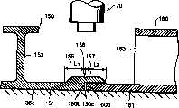
图1示出了构成侧构架41的空心框架构件的接头部分。空心框架构件50和60是用如铝合金制成的挤压框架构件。空心框架构件50、60各包括两块板51、52和61、62以及连接上述两块板的斜板(肋板)53、63。多块斜板53、63被排列成珩架结构。斜板52、63的倾斜方向是交替的。FIG. 1 shows joint portions of the hollow frame members constituting the
一个空心框架构件50的端部被插入另一个空心框架构件60的端部中。连接板51和52的立板54设置在空心框架构件50端部的附近。参考符号54是一个支承空心框架构件50的端部用的挤压件。The end of one
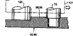
在立板54的厚度方向(在图1中,从右到左)的中心延长线上,待连接的框架构件的端部具有两个空心框架构件50和60的加厚部分(突起部分)。即,各空心框架构件50和60在进行连接的端部(焊接区W的中心)被加厚从而形成突起部分。On the central extension of the
将板51、52和板61、62设置在焊接区W的附近(如见图2)且所述板经挤压变厚而在空心框架构件的前表面一侧上(沿厚度方向的外侧)形成加厚部分,或在面向用作实施连接工作(焊接)的工具的一侧,即面向是用于摩擦搅动焊接的工具的转动体70的那一侧上形成加厚部分。The
加厚部分56和66分别成型于板51、52和板61、62的端部。加厚部分56和66的前表面(外表面)平滑相连且向板51、52和板61、62(非加厚部分,可能是平的)的前表面(外表面)倾斜。当两个加厚部分56和66被对准时,它们可形成图1所示的梯形,然而,本发明不局限于形成梯形的对准的加厚部分56、66。
作为摩擦搅动焊接的连接工具的转动体70和70分别安置在空心框架构件连接区的上侧和下侧。各转动体70在大直径圆棒71(大直径段)的顶端上具有一个小直径圆棒72(小直径段),大直径段作为一基础部分。大直径段71和小直径段72同轴设置。
下转动体70在上转动体70的下方基本上垂直地向下设置。转动体70和70可沿接合线间隔设置,但是为了防止空心框架构件50和60弯曲,最好不使上转动体和下转动体在沿接合线的方向上间隔过远。转动体70的材质比空心框架构件50和60的材质硬。The lower
通过使两个转动体70转动而将小直径段72插入空心框架构件50和60的连接区中。随后,使两个转动体70沿空心框架构件50和60的连接区的纵向作水平移动。这两个转动体70同时移动。The small-
在摩擦搅动焊接的过程中,在上转动体70的一侧,转动体70的大直径段71和小直径段72间的分界部分73(一基本上扁平的部分)定位于上部73a上(所述上部在加厚部分56和66的顶点面一侧且在加厚部分56和66的内部)并且与板51和61的总体部分(非突起部分)的上表面延伸面有一个略微靠上的距离。就是说,当上转动体70的大直径段71伸到加厚部分上表面的下方时(如插入加厚部分中),它不会伸到板51和61的非突起部分下方。During the friction stir welding, on one side of the
在下转动体70一侧,大直径段71和小直径段72间的分界部分73略微在板52和62的总体部分(非突起部分)的下表面延伸面的下方(在加厚部分56和66的顶点面侧与总体部分表面的延长面之间且在加厚部分56和66的内部)。On the lower
即,大直径段71和小直径段72间的分界部分73位于板51和52的非突起部分外表面延长线的外侧且还位于加厚部分56和66的内部。在图1中,线73a标明了分界部分73的一个位置。换句话说,相对于上转动体将大直径段插入在加厚部分的顶点面下方但不在板51和52的非突起部分延长线的下方的位置。相应地插入下转动体的大直径段。That is, the
在进行焊接的情况下,框架构件50和60被安装且固定在一底架上。在下表面的加厚部分的周围部分处没有底架。转动体70的转动中心就是连接区的中心,即这样的中心是立板54的厚度的中心。In the case of welding, the
在图4中描述了各部分尺寸间的关系。在两个加厚部分56和66(两个焊接部分55和56)对接的情况下,这两个加厚部分56和66(两个焊接部分56和66)的顶点宽度W1大于小直径段72的直径d,但小于大直径段71的直径D。The relationship between the dimensions of the various parts is depicted in FIG. 4 . In the case where the two thickened
两个加厚部分56和66(两个焊接部分55和56)的基部的宽度W2大于大直径段71的直径D。两个加厚部分56和66(两个焊接部分55和56)的高度H1大于小直径段72的长度。The width W2 of the bases of the two thickened
当大直径段71的下端位于两个加厚部分56和66(两个焊接部分55和56)的部位73a上时,小直径段72的尖端触及构件55或位于构件55附近。When the lower end of the large-
图2示出了已完成摩擦搅动焊接的状态。图2示出了在图1上侧的连接(焊接)区W。在下侧的连接区与上侧的连接区是对称的。在连接区W的外表面侧上形成了一个指向空心框架构件内侧的凹印K。凸厚部分56T和66T位于凹印K的两侧。Fig. 2 shows the state where the friction stir welding has been completed. FIG. 2 shows the connection (soldering) area W on the upper side of FIG. 1 . The connection area on the lower side is symmetrical to the connection area on the upper side. On the outer surface side of the connection area W is formed an indentation K directed toward the inside of the hollow frame member. The
凸厚部分56T和66T是加厚部分56和66的残余部分。凸厚部分56T和66T包括塑性变形的材料。凹印K的底面位于外侧部位73a处,即从板51和61的外表面向外。The raised
在图1的上侧面是有轨车辆的车体外表面侧的情况下,例如通过磨床对上表面连接区的多余部分(从板51和61的总体部分(非加厚部分)的表面向外伸出的部分)进行机加工且由此形成与板51和61的总体部分的上表面一样的平面。由于上表面侧经过机加工,所以可以很容易地进行切削加工。In the case where the upper side of FIG. 1 is the outside of the car body surface of a rail vehicle, the superfluous part of the upper surface connection zone (extruding from the surface of the general part (non-thickened part) of the
与上述相似地,在下表面侧上存在凹印K和凸厚部分56T和66T。但是,当凹印和凸厚部分位于车体的内表面侧时,由于它们被装饰板盖住了,所以无需进行机加工。Similar to the above, there are indentations K and convex
图3示出了如下所述的状态,即安装在底架111上的框架构件50和60穿过上侧和下侧连接在一起并随后在被安装到底架111上的状态下对上表面侧的凸厚部分56T和66T进行机加工。3 shows a state in which the
根据上述结构,基本上可以防止出现延伸到板51和61的总体部分(非加厚部分)表面下方的凹印K。结果,无需进行堆焊并用腻子修补。According to the above structure, occurrence of the indentation K extending below the surface of the entire portion (non-thickened portion) of the
另外,在上述实施例中,加厚部分56和66的端部56a和66a彼此接触,但是,在加厚部分间存在间隙的情况下,在摩擦搅动焊接时被流化的加厚部分56和66的基体金属被压入上述间隙中。结果,在有间隙的情况下,在连接区内不产生缺陷。In addition, in the above-described embodiment, the
具体地说,当加厚部分的高度(图4中的H1)为1mm时,其间间距为1mm的两个构件可被无缺陷地连接在一起。另外,可以使凹印K位于板51、52和板61、62的外表面的延长线的外侧。即,可以基本上且很容易地防止出现延伸至板61、62和板51、52的表面下的凹印K。Specifically, when the height of the thickened portion (H1 in FIG. 4) is 1 mm, two members with a distance of 1 mm therebetween can be connected together without defects. In addition, the gravure K may be located outside the extension line of the outer surfaces of the
如上所示,根据本发明,两个待连接件可以相互接触,但无需接触;在待连接件的端部之间可以有间隙。根据本文所述,尽管两个待连接构件彼此相邻(对接),但这两个构件可以彼此接触或可具有小的间隙。As shown above, according to the present invention, the two pieces to be connected may be in contact with each other, but need not be in contact; there may be a gap between the ends of the pieces to be connected. As described herein, although two members to be connected are adjacent (butted) to each other, the two members may contact each other or may have a small gap.
例如,加厚部分56和66基部的宽度W2大于大直径段71的直径D。加厚部分56和66的顶点宽度W1大于小直径段72的直径d。当转动体70的中心偏离加厚部分56和66的中心时,上述尺寸是在考虑了两个框架构件间的间距的情况下确定的。For example, the width W2 of the base of the thickened
另外,连接区的加厚部分56和66在被连接到一起时可呈梯形。与加厚部分56和66被挤压成四边形的情况相比,在本发明中不存在多余部分。结果,本发明可节省少量的空心框架构件并且还可以降低生产成本。Additionally, the thickened
另外,可以减少磨床的机加工量,这是因为例如只有加厚部分的残余部分需要机加工。另外,如图6所示,在加厚部分56和66的侧端51a和61a从板51和61的非加厚部分的外表面略微向上突出之后,可以使加厚部分56和66成梯形。In addition, the amount of machining on the grinding machine can be reduced since, for example, only the remainder of the thickening needs to be machined. In addition, as shown in FIG. 6, after the side ends 51a and 61a of the thickened
立板54防止了板51和61在加厚部分56和66因由转动体70引起的压力而弯向内侧。The
在图1中,空心框架构件50的右端结构形状可采用空心框架构件的左端结构形状也可以采用空心框架构件60的右端结构形状。空心框架构件60的结构形状可采用相似结构。总而言之,最好连接两个空心框架构件。In FIG. 1 , the structural shape of the right end of the
通过采用一光学探测器检测对接部位来移动转动体70。通过检测加厚部分56和66的坡面56c和66c来决定转动体70在宽度方向上的位置。如图7所示,用于检测的坡面56n和66n可设置在加厚部分56m和66m的对面。可分别为加厚部分56m和66m或其中之一设置坡面56n(66n)。The rotating
在上述的各实施例中,两个连接区的两个端面56a和66a平行于转动体70的轴心。但是,两个端面56a和66a可相对转动体70的轴心倾斜。例如,构件50的端面56a是倾斜的,另一构件60的端面66a在上侧相对于端面56a是一致的。In the above-mentioned embodiments, the two
根据这种结构,即使当两个端面间的间隙较大时,也可以根据转动体70的转动防止流化金属从挤压件55中流出。这种结构适于连接对接管。According to this structure, even when the gap between both end surfaces is large, fluidized metal can be prevented from flowing out from the extruded
参见图8A来描述连接装置。空心框架构件50和60被安装在底架111上且由夹具113固定住。这两个空心框架构件50和60的对接部分被适当地暂时焊接在一起。See Figure 8A for a description of the attachment means.
上转动体70从一个沿宽度方向运行的移动座121上悬垂下来。移动座121沿门型活动架122的上部构架移动。活动架122沿一个纵向布置在空心框架构件50和60两侧的轨道123运行。The upper
下转动体70设置在一个布置在两个底架111和111之间的移动座131上。移动座131安装在活动架132上并沿宽度方向移动。The lower
活动架132沿轨道133移动且也沿空心框架构件50和60的纵向移动。下转动体70设置在移动座131的上部上。移动座131和121也使转动体70和70沿垂直方向移动。The
许多压紧空心框架构件50和60用的滚轮124和134设置在移动座121和131上。滚轮124和134布置在转动体70和70的前部且位于加厚部分56和66的两侧。必要时,沿运行方向设置多排滚轮124和134。滚轮可加设在转动体70的前面和后面。A plurality of
移动座121和131带有一个可检测待连接位置的探测器(图中未示出)。由探测器使移动座121和131沿宽度方向移动。在用激光作为探测器的情况下,探寻坡面56c,56c和66c,66c并检测待连接中心。The moving
在用转动体70和70分别将空心框架构件50的上、下表面与空心框架60的上、下表面连在一起后且在空心框架构件50和60被安装在底架111上的情况下,通过切削掉上表面的凸厚部分而对空心框架构件50和60进行光滑地精加工。After the upper and lower surfaces of the
当用手动工具进行磨削加工时,所述表面可被加工得更光滑。为此,可以把凸厚部分设置在上表面上以便进行机加工。When grinding with hand tools, the surface can be made smoother. For this purpose, a convex portion may be provided on the upper surface for machining.
另外,首先由于凸厚部分经过机加工后的余量很少且随后用手动工具对残余的凸厚部分进行加工,所以可以缩短切削加工时间。在这种情况下,转动体70不占据移动座121的后部并将切削工具安装在移动座121上。在使转动体70转动的情况下,切削工具进行切削加工。In addition, the machining time can be shortened because first, the convex portion is machined with a small allowance and then the remaining convex portion is machined with a hand tool. In this case, the rotating
例如如图8B和8C所示,参见上表面侧的转动体70的后部,在上表面侧的移动座121上设有一个端部铣床126。端部铣床126切掉凸厚部分56T和66T。端部铣床126的下端位于一个略微离开空心框架构件50和60的上面板51和61的上表面的上部上。端部铣床126的直径比位于上述位置的凸厚部分56T和66T的宽度大许多。滚轮124和134从一上部位和一下部位向下推进到端部铣床126附近并由此使端部铣床126的加工量均匀一致。For example, as shown in FIGS. 8B and 8C , referring to the rear portion of the
在上述实施例中,一对空心框架构件在端部分别具有加厚部分,但是,如图8D所示,可以形成这样的结构,即只有一个空心框架构件具有一加厚部分。加厚部分66的金属在位于空心框架构件50的板的上表面以及空心框架构件50和60之间的间隙中流动。另外,与上述相似地,在一个空心框架构件60中,加厚部分形成于上面板61上,而在另一个空心框架构件50中,下表面52具有加厚部分。In the above embodiment, a pair of hollow frame members have thickened portions at the ends respectively, however, as shown in FIG. 8D, a structure may be formed in which only one hollow frame member has a thickened portion. The metal of the thickened
在上述实施例中,框架构件(如挤压框架构件)被例举为空心框架构件。但是,本发明可用于非空心的(如挤制)框架构件。随后将描述这样的实施例。In the above-described embodiments, the frame members such as extruded frame members are exemplified as hollow frame members. However, the invention can be used with non-hollow (eg extruded) frame members. Such an embodiment will be described later.
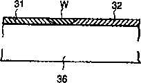
图9示出了一个在板形挤压框架构件31和32的端部具有加厚部分34和35的接头结构的例子,所述框架构件31和32是通过对接加厚部分34和35并进行摩擦搅动焊接而连接起来的。在焊接过程中,挤压框架构件31和32设置在支承工具(底架)36上。为了防止支承工具与连接区W相连,使这些支承工具36由比挤压框架构件31和32的材质硬的材料制成。Figure 9 shows an example of a joint structure having thickened portions 34 and 35 at the ends of plate-shaped
至于接头的对接面,由于转动体70旋转并且移动,所以可获得图10所示的连接区W。转动体70相对加厚部分34和35的位置关系与上述实施例中的位置关系相似。As for the mating face of the joint, since the rotating
随后,如图11所示,用磨床等工具光滑地除去凹印K和凸厚部分。连接装置的滚轮124等构件与上述实施例中的相应构件相似。Subsequently, as shown in FIG. 11, the indentation K and the convex portion are smoothly removed with a grinder or the like. Components such as the
另外,在挤压框架构件等只有一个连接区的情况下,在图8A所示的实施例中,可设置一个支承挤压框架构件用的滚轮以取代下转动体70。在这种结构中,无需支承框架构件31和32的整个表面。结果,可简化底架结构。In addition, in the case of an extruded frame member or the like having only one joint area, a roller for supporting the extruded frame member may be provided instead of the lower
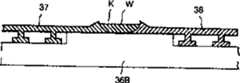
图12-图14所示的实施例示出了各框架构件37和38的一个表面具有许多肋条39的情况。在与具有肋条39的表面相对的表面上,具有加厚部分34b和35b的框架构件37和38通过摩擦搅动焊接方式被连接在一起。底架36B支承肋条39的下端和加厚部分34b和35b的下表面。摩擦搅动焊接的实施过程与上述实施例相似。The embodiment shown in FIGS. 12-14 shows that each
图15-图16所示的实施例示出了具有加厚部分34b和35b的挤制框架构件37c和38c设置在肋条39一侧的情况。在这种结构中,底架36C的一侧变成平面。The embodiment shown in FIGS. 15-16 shows that the extruded
结果,在允许肋条39的相对侧略微不平整的情况下,可以取消使连接区光滑的精加工工序,从而可以低成本地制造连接结构。连接区W是一个连接良好的区域而且它可以获得预定的厚度。As a result, while allowing for slight unevenness on the opposite side of the
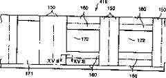
以下描述图17-图19所示的实施例。在图17中,有轨车辆的侧构架416是由许多挤压框架构件150和160构成的。在窗口172和172之间的和在进出口171和窗口172之间的各挤压框架构件150沿图17中的纵向延伸(即所述框架构件的长度方向为上述纵向)。在窗口172的下部和上部的各挤压框架构件160沿图17中的横向延伸(即所述框架构件的长度方向为上述横向)。即,挤压框架构件150和挤压框架构件160(即框架构件长度)沿彼此垂直相交的方向延伸。The embodiments shown in FIGS. 17-19 are described below. In FIG. 17 , the
与上述实施例相似,通过设有加厚部分,同向延伸的(指其长度方向相同)挤压框架构件150和150彼此相连,而且同向延伸的(指其长度方向相同)挤压框架构件160和160彼此相连。Similar to the above-mentioned embodiments, by providing thickened portions, the extruded
图18示出了在框架构件150和160的延伸方向上的相交部分。图18示出了在摩擦搅动焊接前的状态。挤压框架构件150和160在板的一侧各具有一肋条153和163。挤压框架构件150和160不是空心框架构件。挤压框架构件150和160使板151和161支承在底架36C上。肋条153和163指向上部。肋条153和163的侧面是车辆的内侧,而板151和161的侧面是车辆的外侧。FIG. 18 shows the intersection in the extending direction of the
挤压框架构件150的端部被挤压到肋条153的一侧上并且构成了一加厚部分156。加厚部分156被进一步挤压向待焊接的挤压框架构件160并构成一挤压部分157。挤压部分157与挤压框架构件160的板161的内侧(肋条163侧)搭接。部分挤压部分157的肋条163被切除。例如,挤压部分157的挤压量等于加厚部分156的宽度L1,即挤压部分157对应于加厚部分156。挤压部分157的尖端与加厚部分156相似地具有一个侧斜面。The end of the extruded
由于从上部插入转动体70,所以当进行摩擦搅动焊接时,由于挤压部分157叠置在位于这两个挤压框架构件150和160的端部150b和160b之间的间隙150c上而使挤压部分157的金属等流向间隙150c。另外,金属也流向挤压框架构件160的上部。结果,与不带有加厚部分156和挤压部分157的情况相比并且进一步地与不只带有挤压部分157的情况相比,可以在上述的情况下获得良好的焊接效果。Since the rotating
由于通过切除挤压框架构件160的肋条163且由挤压部分157覆盖挤压框架构件160,所以在挤压部分157附近的板161可被压下并可获得良好的焊接效果。Since the extruded
三角形槽158开设于位于挤压框架构件150的端部150b和挤压框架构件160的端部160b间的加厚部分156的外表面上。此槽158起到了用于最初确定转动体70的位置的位标的作用。此槽158还用作一个用于探测器的标记。A
图20示出了在肋条153侧未设置加厚部分156和挤压部分157的情况。肋条153和163安置在底架36B上。加厚部分156、挤压部分157和环绕这两部分的板151和161安置在一个从底架36B向上部伸出的底架上。在挤压框架构件160端部附近的肋条163被切除。使挤压框架构件150的加厚部分156和挤压部分157位于板151侧(车辆的外表面侧)。FIG. 20 shows the case where the thickened
在焊接挤压方向直交的框架构件的情况下,可以采用只有一个加厚部分156而不带挤压部分157的结构。另外,挤压部分朝相邻构件设置的结构可适用于空心挤压框架构件等。另外,挤压部分结构可适用于连接两个非直交的挤压框架构件即适用于焊接两个平行构件。In the case of welding the frame members perpendicular to the extrusion direction, a structure with only one thickened
上述方法可适用于对接蜂窝板。各蜂窝板包括两个面板、一个位于这两个面板之间的蜂窝式芯件、以及一个设置在芯件的周围部分上的凸缘件等。The above method can be applied to butt honeycomb panels. Each honeycomb panel includes two face sheets, a honeycomb core located between the two face sheets, a flange provided on a peripheral portion of the core, and the like.
待连接的客体可以是管件等。在这种情况下,上述实施例的板可适当地由一个圆柱体取代。The objects to be connected may be pipe fittings and the like. In this case, the plates of the above-described embodiments may suitably be replaced by a cylinder.
可以通过采用本发明而避免产生延伸到连接件的表面下方的凹印。因此,可以简化连接件的精加工,所述精加工是为了产生一个穿过所述连接件间的接头的光滑表面。Indentations extending below the surface of the connector can be avoided by employing the present invention. As a result, the finishing of the connectors in order to produce a smooth surface across the joint between the connectors can be simplified.
另外,即使在将通过摩擦搅动焊接连接的构件之间有一处或多处间隙且这些间隙较大时,也可以避免产生延伸到连接件表面下方的凹印,由此简化提供一个穿过接头的光滑表面的精加工工作。In addition, even when there are one or more gaps between the members to be joined by friction stir welding and these gaps are large, it is possible to avoid indentations extending below the surface of the joint, thereby simplifying the provision of a joint through the joint. Finishing work on smooth surfaces.
在不超出本发明的精神或实质特征的前提下,可以通过其它具体方式实施本发明。因此,从各个方面看,上述实施例应被认为是示意性的实施例而不是限定性的实施例。本发明的范围是由随后的权利要求书限定的而不是由上述说明书限定的。所以,所有落入权利要求的等同替换方式的范围和目的中的改动都包含在本权利要求书中。The present invention can be implemented in other specific ways without departing from the spirit or essential characteristics of the present invention. Therefore, the above-described embodiments should be considered as illustrative embodiments and not restrictive embodiments in all respects. The scope of the invention is defined by the following claims rather than by the foregoing description. Therefore, all changes that come within the scope and purpose of equivalent alternatives of the claims are included in the claims.
Claims (6)
Applications Claiming Priority (2)
| Application Number | Priority Date | Filing Date | Title |
|---|---|---|---|
| JP196759/1997 | 1997-07-23 | ||
| JP19675997 | 1997-07-23 |
Related Parent Applications (1)
| Application Number | Title | Priority Date | Filing Date |
|---|---|---|---|
| CNB011089067ADivisionCN100404188C (en) | 1997-07-23 | 2001-02-28 | Friction welding equipment |
Publications (2)
| Publication Number | Publication Date |
|---|---|
| CN1541799A CN1541799A (en) | 2004-11-03 |
| CN1281366Ctrue CN1281366C (en) | 2006-10-25 |
Family
ID=16363157
Family Applications (15)
| Application Number | Title | Priority Date | Filing Date |
|---|---|---|---|
| CNB011089059AExpired - Fee RelatedCN1292870C (en) | 1997-07-23 | 1998-04-28 | Friction stirring welding method, frame member used thereof and product produced therefrom |
| CNB2004100070566AExpired - Fee RelatedCN1298483C (en) | 1997-07-23 | 1998-04-28 | Friction stir welding method, frame members used therein, and product formed thereby |
| CNB011109262AExpired - Fee RelatedCN100417486C (en) | 1997-07-23 | 1998-04-28 | Friction welding method and structure |
| CNB011109270AExpired - LifetimeCN100453242C (en) | 1997-07-23 | 1998-04-28 | structure |
| CNB2004100473459AExpired - Fee RelatedCN1281366C (en) | 1997-07-23 | 1998-04-28 | Friction stir welding method, frame components used thereof and products made thereby |
| CNB2004100070551AExpired - Fee RelatedCN1298482C (en) | 1997-07-23 | 1998-04-28 | Friction stir welding method, frame members used therein, and product formed thereby |
| CNB011109254AExpired - LifetimeCN100418691C (en) | 1997-07-23 | 1998-04-28 | Friction welding method and structure |
| CNB2004100070570AExpired - Fee RelatedCN1298484C (en) | 1997-07-23 | 1998-04-28 | Friction stir welding method, frame members used therein, and product formed thereby |
| CNB011109246AExpired - LifetimeCN1177668C (en) | 1997-07-23 | 1998-04-28 | Extruded Frame Members for Friction Stir Welding |
| CNB2004100473463AExpired - Fee RelatedCN100339174C (en) | 1997-07-23 | 1998-04-28 | Friction stir welding method, frame members used therein, and product formed thereby |
| CNB2004100070547AExpired - Fee RelatedCN1318175C (en) | 1997-07-23 | 1998-04-28 | Friction stir welding method, frame members used therein, and product formed thereby |
| CN98107776AExpired - LifetimeCN1090071C (en) | 1997-07-23 | 1998-04-28 | Friction Stir Welding Method |
| CNB011089067AExpired - LifetimeCN100404188C (en) | 1997-07-23 | 2001-02-28 | Friction welding equipment |
| CNB01110922XAExpired - LifetimeCN1174830C (en) | 1997-07-23 | 2001-03-02 | Extruded Frame Members for Friction Stir Welding |
| CNB011109238AExpired - Fee RelatedCN1174831C (en) | 1997-07-23 | 2001-03-02 | Friction stir welding method, frame members used therein and products made therefrom |
Family Applications Before (4)
| Application Number | Title | Priority Date | Filing Date |
|---|---|---|---|
| CNB011089059AExpired - Fee RelatedCN1292870C (en) | 1997-07-23 | 1998-04-28 | Friction stirring welding method, frame member used thereof and product produced therefrom |
| CNB2004100070566AExpired - Fee RelatedCN1298483C (en) | 1997-07-23 | 1998-04-28 | Friction stir welding method, frame members used therein, and product formed thereby |
| CNB011109262AExpired - Fee RelatedCN100417486C (en) | 1997-07-23 | 1998-04-28 | Friction welding method and structure |
| CNB011109270AExpired - LifetimeCN100453242C (en) | 1997-07-23 | 1998-04-28 | structure |
Family Applications After (10)
| Application Number | Title | Priority Date | Filing Date |
|---|---|---|---|
| CNB2004100070551AExpired - Fee RelatedCN1298482C (en) | 1997-07-23 | 1998-04-28 | Friction stir welding method, frame members used therein, and product formed thereby |
| CNB011109254AExpired - LifetimeCN100418691C (en) | 1997-07-23 | 1998-04-28 | Friction welding method and structure |
| CNB2004100070570AExpired - Fee RelatedCN1298484C (en) | 1997-07-23 | 1998-04-28 | Friction stir welding method, frame members used therein, and product formed thereby |
| CNB011109246AExpired - LifetimeCN1177668C (en) | 1997-07-23 | 1998-04-28 | Extruded Frame Members for Friction Stir Welding |
| CNB2004100473463AExpired - Fee RelatedCN100339174C (en) | 1997-07-23 | 1998-04-28 | Friction stir welding method, frame members used therein, and product formed thereby |
| CNB2004100070547AExpired - Fee RelatedCN1318175C (en) | 1997-07-23 | 1998-04-28 | Friction stir welding method, frame members used therein, and product formed thereby |
| CN98107776AExpired - LifetimeCN1090071C (en) | 1997-07-23 | 1998-04-28 | Friction Stir Welding Method |
| CNB011089067AExpired - LifetimeCN100404188C (en) | 1997-07-23 | 2001-02-28 | Friction welding equipment |
| CNB01110922XAExpired - LifetimeCN1174830C (en) | 1997-07-23 | 2001-03-02 | Extruded Frame Members for Friction Stir Welding |
| CNB011109238AExpired - Fee RelatedCN1174831C (en) | 1997-07-23 | 2001-03-02 | Friction stir welding method, frame members used therein and products made therefrom |
Country Status (6)
| Country | Link |
|---|---|
| US (14) | US6050474A (en) |
| EP (12) | EP1462205B1 (en) |
| JP (5) | JP3070735B2 (en) |
| KR (11) | KR100428535B1 (en) |
| CN (15) | CN1292870C (en) |
| DE (12) | DE69840950D1 (en) |
Families Citing this family (260)
| Publication number | Priority date | Publication date | Assignee | Title |
|---|---|---|---|---|
| NO954273D0 (en)* | 1995-10-26 | 1995-10-26 | Norsk Hydro As | Wheels Wheel |
| CN1165403C (en)* | 1996-03-19 | 2004-09-08 | 株式会社日立制作所 | Components for friction welding |
| JP4406092B2 (en)* | 1997-05-16 | 2010-01-27 | エサブ アクチボラゲット | Welding assembly for rotary friction welding |
| GB9713209D0 (en)* | 1997-06-20 | 1997-08-27 | British Aerospace | Friction welding metal components |
| JP3070735B2 (en)* | 1997-07-23 | 2000-07-31 | 株式会社日立製作所 | Friction stir welding method |
| JP3589863B2 (en)* | 1997-07-23 | 2004-11-17 | 株式会社日立製作所 | Structure and friction stir welding method |
| SE9704800D0 (en)* | 1997-12-19 | 1997-12-19 | Esab Ab | Device for welding |
| JP3333728B2 (en)* | 1997-12-25 | 2002-10-15 | 東海ゴム工業株式会社 | Bush mounting member and method of manufacturing the same |
| US6290117B1 (en)* | 1998-02-17 | 2001-09-18 | Hitachi, Ltd. | Friction stir welding method and friction stir welding apparatus |
| JP3420502B2 (en)* | 1998-06-16 | 2003-06-23 | 株式会社日立製作所 | Structure |
| US6745929B1 (en)* | 1998-06-16 | 2004-06-08 | Hitachi, Ltd. | Method of manufacturing structural body and structural body |
| JP4004150B2 (en)* | 1998-09-11 | 2007-11-07 | 本田技研工業株式会社 | Rear cushion bracket mounting structure |
| ES2281134T3 (en)* | 1998-09-28 | 2007-09-16 | Hitachi, Ltd. | BODYWORK. |
| AU733140B2 (en)* | 1998-09-29 | 2001-05-10 | Hitachi Limited | A friction stir welding method |
| US7748233B2 (en) | 1998-12-23 | 2010-07-06 | S.I.P. Technologies L.L.C. | Sanitized water dispenser |
| US7175054B2 (en)* | 1998-12-23 | 2007-02-13 | S.I.P. Technologies, Llc | Method and apparatus for disinfecting a refrigerated water cooler reservoir |
| US6247633B1 (en)* | 1999-03-02 | 2001-06-19 | Ford Global Technologies, Inc. | Fabricating low distortion lap weld construction |
| WO2000056497A1 (en)* | 1999-03-24 | 2000-09-28 | Framatome Anf Gmbh | Method and device for welding two work pieces |
| JP3459193B2 (en)* | 1999-05-26 | 2003-10-20 | 株式会社日立製作所 | Method of repairing friction stir welding and method of manufacturing railway vehicle |
| TW464576B (en)* | 1999-05-28 | 2001-11-21 | Hitachi Ltd | A structure body and a manufacturing method of a structure body |
| TW460346B (en)* | 1999-05-28 | 2001-10-21 | Hitachi Ltd | A manufacturing method of a structure body and a manufacturing apparatus of a structure body |
| JP3481501B2 (en)* | 1999-05-28 | 2003-12-22 | 株式会社日立製作所 | Structure and method of manufacturing the same |
| JP3868695B2 (en)* | 1999-05-28 | 2007-01-17 | 株式会社日立製作所 | Manufacturing method of structure |
| TW449519B (en) | 1999-05-31 | 2001-08-11 | Hitachi Ltd | A manufacturing method of a structure body |
| JP2000343245A (en)* | 1999-05-31 | 2000-12-12 | Hitachi Ltd | How to make a structure |
| AU7475200A (en)* | 1999-09-03 | 2001-04-10 | Lockheed Martin Corporation | Friction stir welding as a rivet replacement technology |
| JP3563003B2 (en)* | 1999-09-30 | 2004-09-08 | 株式会社日立製作所 | Friction stir welding method for structures |
| DE19957136C1 (en)* | 1999-11-18 | 2001-02-08 | Geesthacht Gkss Forschung | Friction welding appts has a projecting and rotating pin to act on the workpiece materials at the welding zone to follow the welding line and soften the materials to fuse together and bond sheet plates with complex shapes |
| JP3459210B2 (en)* | 1999-11-24 | 2003-10-20 | 株式会社日立製作所 | Friction stir welding method |
| US6722286B2 (en)* | 1999-12-14 | 2004-04-20 | Hitachi, Ltd. | Structure and railway car |
| JP3538357B2 (en)* | 2000-01-24 | 2004-06-14 | 株式会社日立製作所 | Friction stir welding method |
| JP3552978B2 (en)* | 2000-01-27 | 2004-08-11 | 株式会社日立製作所 | Hollow profile |
| US6299050B1 (en)* | 2000-02-24 | 2001-10-09 | Hitachi, Ltd. | Friction stir welding apparatus and method |
| JP3589930B2 (en)* | 2000-02-25 | 2004-11-17 | 株式会社日立製作所 | Friction stir welding method |
| US6237835B1 (en)* | 2000-02-29 | 2001-05-29 | The Boeing Company | Method and apparatus for backing up a friction stir weld joint |
| JP3575748B2 (en) | 2000-03-06 | 2004-10-13 | 株式会社日立製作所 | Friction stir welding method |
| US6367681B1 (en)* | 2000-04-04 | 2002-04-09 | The Boeing Company | Friction stir welding apparatus and method |
| JP2001293582A (en) | 2000-04-13 | 2001-10-23 | Nissan Motor Co Ltd | Aluminum links |
| JP3867475B2 (en)* | 2000-04-28 | 2007-01-10 | マツダ株式会社 | Method for processing metal members |
| JP3400409B2 (en)* | 2000-04-28 | 2003-04-28 | マツダ株式会社 | Joining method and joining device |
| MXPA02010936A (en) | 2000-05-08 | 2004-09-06 | Univ Brigham Young | Friction stir weldin of metal matrix composites, ferrous alloys, non ferrous alloys, and superalloys using a superabrasive tool. |
| JP3429475B2 (en)* | 2000-05-08 | 2003-07-22 | 川崎重工業株式会社 | Spot joining apparatus and spot joining method |
| JP3781099B2 (en)* | 2000-06-02 | 2006-05-31 | トヨタ自動車株式会社 | Hollow product, fluid processing system, and method for joining hollow members |
| JP3274453B2 (en)* | 2000-06-05 | 2002-04-15 | 川崎重工業株式会社 | Joint failure detection method in friction stir welding |
| JP4467723B2 (en)* | 2000-06-30 | 2010-05-26 | 昭和電工株式会社 | Friction stir welding method |
| US6352193B1 (en) | 2000-08-01 | 2002-03-05 | General Electric Company | Apparatus for joining electrically conductive materials |
| US6619533B1 (en)* | 2000-09-22 | 2003-09-16 | Tower Automotive Technology Products, Inc. | Multi-piece extruded link arm |
| JP3538378B2 (en)* | 2000-10-27 | 2004-06-14 | 株式会社日立製作所 | Friction stir welding method |
| JP3763734B2 (en)* | 2000-10-27 | 2006-04-05 | 株式会社日立製作所 | Panel member processing method |
| JP3553012B2 (en)* | 2000-11-17 | 2004-08-11 | 株式会社日立製作所 | Friction stir welding method |
| JP3575749B2 (en)* | 2000-11-17 | 2004-10-13 | 株式会社日立製作所 | Friction stir welding method |
| JP4723081B2 (en)* | 2000-11-29 | 2011-07-13 | 株式会社日立製作所 | Manufacturing method of structure |
| DE10059847B4 (en)* | 2000-11-30 | 2005-07-14 | Webasto Ag | Heat exchanger for vehicle heaters |
| US6769595B2 (en)* | 2000-12-20 | 2004-08-03 | Alcoa Inc. | Friction plunge riveting |
| JP3761786B2 (en) | 2001-01-17 | 2006-03-29 | 株式会社日立製作所 | Friction stir welding method and apparatus |
| US20030111514A1 (en)* | 2001-01-23 | 2003-06-19 | Naoki Miyanagi | Method of friction welding, and frictionally welded structure |
| JP2002239756A (en)* | 2001-02-14 | 2002-08-28 | Nissan Motor Co Ltd | Friction stir welding method and apparatus |
| JP2002273579A (en)* | 2001-03-15 | 2002-09-25 | Hitachi Ltd | Method of joining iron-based material and its structure |
| US6550397B2 (en) | 2001-03-27 | 2003-04-22 | Hitachi, Ltd. | Car body |
| JP3751215B2 (en)* | 2001-04-16 | 2006-03-01 | 株式会社日立製作所 | Friction stir welding method |
| US6582539B2 (en)* | 2001-06-08 | 2003-06-24 | Lockheed Martin Corporation | Method for making large composite structures without use of an autoclave |
| US6732901B2 (en)* | 2001-06-12 | 2004-05-11 | Brigham Young University Technology Transfer Office | Anvil for friction stir welding high temperature materials |
| JP3471338B2 (en)* | 2001-07-30 | 2003-12-02 | 川崎重工業株式会社 | Friction stir welding equipment |
| JP3751236B2 (en)* | 2001-08-24 | 2006-03-01 | 株式会社日立製作所 | Friction stir welding method |
| JP3507050B2 (en)* | 2001-09-25 | 2004-03-15 | 住友軽金属工業株式会社 | Friction stir welding method |
| US20030075584A1 (en)* | 2001-10-04 | 2003-04-24 | Sarik Daniel J. | Method and apparatus for friction stir welding |
| US6910616B2 (en) | 2002-03-07 | 2005-06-28 | The Boeing Company | Preforms for forming machined structural assemblies |
| JP3795824B2 (en)* | 2002-04-16 | 2006-07-12 | 株式会社日立製作所 | Friction stir welding method |
| DE10224198C1 (en)* | 2002-05-31 | 2003-08-14 | Erbsloeh Ag | Light structural element has encompassing circle with diameter of at least 300 mm and wall thickness of maximum of 5 per cent of this |
| DE10226526A1 (en)* | 2002-06-14 | 2003-08-07 | Daimler Chrysler Ag | Running gear frame has interconnected frame sections with at least one frame section seam as a friction stir welded seam which extends three-dimensionally, and at least two frame sections are differently constructed |
| JP3726786B2 (en)* | 2002-07-31 | 2005-12-14 | マツダ株式会社 | Joining method and joining tool |
| RU2325981C2 (en) | 2002-08-07 | 2008-06-10 | Иклипс Эйвиейшн Корпорейшн | Weldes with a polymer sealer |
| KR100868269B1 (en)* | 2002-08-28 | 2008-11-11 | 한라공조주식회사 | Cylindrical material joining device and method |
| JP4633999B2 (en)* | 2002-09-11 | 2011-02-16 | 株式会社日立製作所 | How to make a car body |
| JP4647179B2 (en)* | 2002-09-11 | 2011-03-09 | 株式会社日立製作所 | Processing method |
| US6779708B2 (en) | 2002-12-13 | 2004-08-24 | The Boeing Company | Joining structural members by friction welding |
| JP4292248B2 (en)* | 2003-01-23 | 2009-07-08 | 敏博 福元 | A self-propelled vehicle with a function to change the shape of the frame structure |
| JP2006518671A (en)* | 2003-01-30 | 2006-08-17 | スミス インターナショナル、インコーポレテッド | Out-of-position friction stir welding of high melting point materials |
| US6908145B2 (en)* | 2003-02-10 | 2005-06-21 | Ford Global Technologies, Llc | Vehicle passenger compartment components and manufacturing process for making the same |
| JP2004298955A (en)* | 2003-04-01 | 2004-10-28 | Hitachi Ltd | Friction stir welding method |
| WO2004091839A2 (en)* | 2003-04-11 | 2004-10-28 | Edison Welding Institute | Method and apparatus for locally clamping components that are to be joined by friction stir welding |
| US6758382B1 (en) | 2003-05-02 | 2004-07-06 | The United States Of America As Represented By The Administrator Of The National Aeronautics And Space Administration | Auto-adjustable tool for self-reacting and conventional friction stir welding |
| WO2004101205A2 (en)* | 2003-05-05 | 2004-11-25 | Smith International, Inc. | Applications of friction stir welding using a superabrasive tool |
| US20060138197A1 (en)* | 2003-06-12 | 2006-06-29 | Kinya Aota | Friction stirring-welding method |
| JP4134837B2 (en)* | 2003-07-15 | 2008-08-20 | マツダ株式会社 | Friction welding method and friction welding structure |
| US7225968B2 (en)* | 2003-08-04 | 2007-06-05 | Sii Megadiamond, Inc. | Crack repair using friction stir welding on materials including metal matrix composites, ferrous alloys, non-ferrous alloys, and superalloys |
| US7448528B2 (en)* | 2003-08-12 | 2008-11-11 | The Boeing Company | Stir forming apparatus and method |
| JP4205537B2 (en) | 2003-09-04 | 2009-01-07 | 株式会社日立製作所 | Friction stir welding method |
| US8266800B2 (en) | 2003-09-10 | 2012-09-18 | Siemens Energy, Inc. | Repair of nickel-based alloy turbine disk |
| US7494040B2 (en)* | 2003-09-25 | 2009-02-24 | Sii Megadiamond, Inc. | Friction stir welding improvements for metal matrix composites, ferrous alloys, non-ferrous alloys, and superalloys using a superabrasive tool |
| US20050070374A1 (en)* | 2003-09-29 | 2005-03-31 | Technology Licensing, Llc | Enhanced golf club performance via friction stir processing |
| KR100543160B1 (en)* | 2003-10-01 | 2006-01-20 | 한국기계연구원 | Surface moving friction welding method for thin plate welding |
| US7422684B1 (en) | 2003-10-16 | 2008-09-09 | S.I.P. Technologies, L.L.C. | Method and apparatus for sanitizing water dispensed from a water dispenser having a reservoir |
| US20050115456A1 (en)* | 2003-10-17 | 2005-06-02 | Hideyuki Nakamura | Structural body of railway car and joint structure for friction stir welding |
| US7128948B2 (en)* | 2003-10-20 | 2006-10-31 | The Boeing Company | Sprayed preforms for forming structural members |
| US7404512B2 (en)* | 2003-10-31 | 2008-07-29 | The Boeing Company | Clamping apparatus and methods for manufacturing |
| WO2005053890A2 (en)* | 2003-11-26 | 2005-06-16 | Advanced Metal Products, Inc. | Method for metal and alloy joining using bulk friction stir welding |
| US7398911B2 (en)* | 2003-12-16 | 2008-07-15 | The Boeing Company | Structural assemblies and preforms therefor formed by friction welding |
| US7225967B2 (en)* | 2003-12-16 | 2007-06-05 | The Boeing Company | Structural assemblies and preforms therefor formed by linear friction welding |
| ITBO20030764A1 (en)* | 2003-12-19 | 2005-06-20 | Ferrari Spa | METAL FRAME CONSISTS OF THE UNION OF A PLURALITY OF EXTRUDED ELEMENTS AND METHOD FOR ITS REALIZATION |
| US20050199372A1 (en)* | 2004-03-08 | 2005-09-15 | Frazer James T. | Cold plate and method of making the same |
| US20060032891A1 (en)* | 2004-03-24 | 2006-02-16 | Flak Richard A | Solid state processing of materials through friction stir processing and friction stir mixing |
| US8186561B2 (en)* | 2004-03-24 | 2012-05-29 | Megastir Technologies, LLC | Solid state processing of hand-held knife blades to improve blade performance |
| US7686825B2 (en) | 2004-03-25 | 2010-03-30 | Hauser David L | Vascular filter device |
| US7886933B2 (en)* | 2004-05-07 | 2011-02-15 | Daio Paper Corporation | Household sanitary tissue paper container |
| US20060049234A1 (en)* | 2004-05-21 | 2006-03-09 | Flak Richard A | Friction stirring and its application to drill bits, oil field and mining tools, and components in other industrial applications |
| US20100078224A1 (en) | 2004-05-21 | 2010-04-01 | Smith International, Inc. | Ball hole welding using the friction stir welding (fsw) process |
| JP2006116597A (en) | 2004-09-21 | 2006-05-11 | Hitachi Ltd | Profile processing apparatus and profile processing method |
| CN100584510C (en)* | 2004-10-05 | 2010-01-27 | Sii米加钻石公司 | Expandable mandrel for use in friction stir welding and method of providing the mandrel |
| US20060157531A1 (en)* | 2004-12-17 | 2006-07-20 | Packer Scott M | Single body friction stir welding tool for high melting temperature materials |
| US7357292B2 (en)* | 2005-02-01 | 2008-04-15 | Battelle Energy Alliance, Llc | Friction stir welding tool |
| DE102005008062A1 (en)* | 2005-02-22 | 2006-08-24 | Siemens Ag | Connection of two aluminum pieces by either melt welding or frictional stir welding uses an inlaid strip in a groove between the two pieces |
| US7356897B2 (en)* | 2005-05-11 | 2008-04-15 | The Boeing Company | Systems and methods for verifying a pre-programmed materials processing path |
| DE102005029882A1 (en)* | 2005-06-27 | 2006-12-28 | Gkss-Forschungszentrum Geesthacht Gmbh | Friction stir welding apparatus includes first inner segment surrounding a pin and having first friction surface segment surrounding the first inner segment and rotationally driven independently of the first inner segment |
| US7597236B2 (en)* | 2005-08-16 | 2009-10-06 | Battelle Energy Alliance, Llc | Method for forming materials |
| US7508682B2 (en)* | 2005-09-19 | 2009-03-24 | Hitachi, Ltd. | Housing for an electronic circuit |
| US8632850B2 (en) | 2005-09-26 | 2014-01-21 | Schultz-Creehan Holdings, Inc. | Friction fabrication tools |
| US9511445B2 (en) | 2014-12-17 | 2016-12-06 | Aeroprobe Corporation | Solid state joining using additive friction stir processing |
| US20080041921A1 (en) | 2005-09-26 | 2008-02-21 | Kevin Creehan | Friction stir fabrication |
| US8875976B2 (en) | 2005-09-26 | 2014-11-04 | Aeroprobe Corporation | System for continuous feeding of filler material for friction stir welding, processing and fabrication |
| US9511446B2 (en) | 2014-12-17 | 2016-12-06 | Aeroprobe Corporation | In-situ interlocking of metals using additive friction stir processing |
| US9266191B2 (en) | 2013-12-18 | 2016-02-23 | Aeroprobe Corporation | Fabrication of monolithic stiffening ribs on metallic sheets |
| US8397974B2 (en) | 2005-09-26 | 2013-03-19 | Aeroprobe Corporation | Self-reacting friction stir welding tool with the ability to add filler material |
| JP4586698B2 (en)* | 2005-09-29 | 2010-11-24 | マツダ株式会社 | Friction spot welding device |
| US8550326B2 (en) | 2005-10-05 | 2013-10-08 | Megastir Technologies Llc | Expandable mandrel for use in friction stir welding |
| US8056797B2 (en)* | 2005-10-05 | 2011-11-15 | Megastir Technologies | Expandable mandrel for use in friction stir welding |
| DE102005048001B4 (en)* | 2005-10-06 | 2007-06-14 | Euro-Composites S.A., Zone Industrielle | connecting element |
| US7353978B2 (en)* | 2005-10-13 | 2008-04-08 | The Boeing Company | Method of making tailored blanks using linear friction welding |
| US20070090516A1 (en)* | 2005-10-18 | 2007-04-26 | Applied Materials, Inc. | Heated substrate support and method of fabricating same |
| DE102005061007A1 (en)* | 2005-12-20 | 2007-06-28 | Siemens Ag | Composite system for a wall or floor structure |
| CA2640730A1 (en)* | 2006-01-31 | 2007-08-09 | Sii Megadiamond, Inc. | Thermally enhanced tool for friction stirring |
| US7843834B2 (en)* | 2006-09-15 | 2010-11-30 | Itron, Inc. | Use of minimal propagation delay path to optimize a mesh network |
| CN100413635C (en)* | 2006-09-29 | 2008-08-27 | 哈尔滨工业大学 | A device for controlling welding stress and deformation with welding friction extrusion |
| CN102267006B (en)* | 2006-10-02 | 2016-08-03 | 日本轻金属株式会社 | Joint method |
| JP4882004B2 (en)* | 2006-11-03 | 2012-02-22 | 株式会社東洋鋼鐵 | Manufacturing apparatus and manufacturing method for reinforcing frame for display panel using aluminum alloy extruded material |
| US20080217377A1 (en)* | 2007-03-06 | 2008-09-11 | Alcoa Inc. | Fracture Resistant Friction Stir Welding Tool |
| US20080230584A1 (en)* | 2007-03-19 | 2008-09-25 | The Boeing Company | Method for Manufacturing a Workpiece by Friction Welding to Reduce the Occurrence of Abnormal Grain Growth |
| US8133345B2 (en)* | 2007-04-05 | 2012-03-13 | Curtis Goad | Method and apparatus for lining process tanks |
| US10138053B2 (en) | 2007-04-05 | 2018-11-27 | Curtis Goad | Methods and apparatus for lining process tanks |
| US9278478B2 (en) | 2007-04-05 | 2016-03-08 | Curtis Goad | Methods and apparatus for lining process tanks |
| WO2009022507A1 (en)* | 2007-08-10 | 2009-02-19 | Nippon Light Metal Company, Ltd. | Joining method and method of manufacturing joint structure |
| US7793816B2 (en)* | 2007-09-07 | 2010-09-14 | Alcoa Inc. | Friction stir welding apparatus |
| US7780061B2 (en)* | 2007-09-27 | 2010-08-24 | The Boeing Company | Joining fixtures, methods for joining, and joined structures |
| CA2706955A1 (en)* | 2007-11-28 | 2009-06-04 | Frank's International, Inc. | Methods and apparatus for forming tubular strings |
| US8401507B2 (en)* | 2007-12-21 | 2013-03-19 | Motorola Mobility Llc | Automatic gain control for beamformed signals |
| US7854362B2 (en)* | 2008-03-14 | 2010-12-21 | Alcoa Inc. | Advanced multi-shouldered fixed bobbin tools for simultaneous friction stir welding of multiple parallel walls between parts |
| US7762447B2 (en)* | 2008-03-20 | 2010-07-27 | Ut-Battelle, Llc | Multiple pass and multiple layer friction stir welding and material enhancement processes |
| JP4607206B2 (en)* | 2008-05-19 | 2011-01-05 | 株式会社日立製作所 | Friction stir welding shape and friction stir welding structure |
| JP4607207B2 (en)* | 2008-05-19 | 2011-01-05 | 株式会社日立製作所 | Friction stir welding method |
| US20090294511A1 (en)* | 2008-05-30 | 2009-12-03 | Vanderbilt University | Lateral position detection for friction stir systems |
| JP4854707B2 (en)* | 2008-06-16 | 2012-01-18 | 川崎重工業株式会社 | Railcar structures |
| US8356772B2 (en)* | 2008-08-12 | 2013-01-22 | Airbus Operations Gmbh | Lightweight structure |
| DE102008041172B9 (en)* | 2008-08-12 | 2014-03-13 | Airbus Operations Gmbh | Aircraft with a fuselage structure with welded skin panels |
| DE102008044087A1 (en)* | 2008-11-26 | 2010-05-27 | Airbus Deutschland Gmbh | Method of making lap joint welds and overlap butt weld joint |
| US8322176B2 (en)* | 2009-02-11 | 2012-12-04 | Ford Global Technologies, Llc | System and method for incrementally forming a workpiece |
| DE102009050775B4 (en)* | 2009-10-27 | 2012-06-06 | Audi Ag | Composite profile consisting of at least a first and second metal profile part |
| KR101548792B1 (en) | 2009-11-02 | 2015-08-31 | 메가스터 테크놀로지스, 엘엘씨 | Out of position friction stir welding of casing and small diameter tubing or pipe |
| JP5544855B2 (en)* | 2009-12-10 | 2014-07-09 | 株式会社ジェイテクト | Propeller shaft |
| KR101455561B1 (en)* | 2010-01-15 | 2014-10-27 | 미츠비시 쥬고교 가부시키가이샤 | Method for producing joint member and friction stir welding apparatus |
| JP5165005B2 (en)* | 2010-01-25 | 2013-03-21 | 川崎重工業株式会社 | Railway vehicle |
| US8033443B1 (en)* | 2010-05-25 | 2011-10-11 | GM Global Technology Operations LLC | Anvil with rolling elements for friction stir welding |
| DE102010032402A1 (en)* | 2010-07-27 | 2012-02-02 | Airbus Operations Gmbh | Method of joining two aircraft body segments by means of friction stir welding |
| AT509066B1 (en)* | 2010-08-11 | 2011-06-15 | Stirzone Og | DEVICE FOR REINFORCING WELDING |
| JP5422535B2 (en)* | 2010-10-27 | 2014-02-19 | 三菱重工業株式会社 | Side structure of vehicle body and manufacturing method thereof |
| CN103459081B (en)* | 2011-01-19 | 2016-05-25 | 日本轻金属株式会社 | Rotary tool unit, friction stir welding method, assembly of double-layer panels, and friction stir welding method of double-layer panels |
| US8590767B2 (en)* | 2011-06-21 | 2013-11-26 | Research Institute Of Industrial Science & Technology | Method for welding hollow structure |
| US9095927B2 (en) | 2011-08-19 | 2015-08-04 | Nippon Light Metal Company, Ltd. | Friction stir welding method |
| JP5567530B2 (en)* | 2011-08-19 | 2014-08-06 | 日立オートモティブシステムズ株式会社 | Friction stir welding structure and power semiconductor device |
| DE102011112042A1 (en)* | 2011-09-01 | 2013-03-07 | Airbus Operations Gmbh | Friction friction welding method for connecting plate-shaped workpieces and apparatus therefor |
| FI126050B (en)* | 2011-10-17 | 2016-06-15 | Uponor Infra Oy | Three-dimensional constructions |
| FI126176B (en)* | 2011-10-17 | 2016-07-29 | Uponor Infra Oy | A method for manufacturing a sheet structure |
| CN102528274B (en)* | 2012-01-10 | 2014-04-09 | 沈阳航空航天大学 | Process for eliminating surface indentation of friction stir welding heads and special edge extrusion equipment |
| JP5970692B2 (en)* | 2012-03-06 | 2016-08-17 | 日本軽金属株式会社 | Method for joining members, method for manufacturing freight transport vehicle, and method for manufacturing freight transport container |
| JP5966178B2 (en)* | 2012-03-06 | 2016-08-10 | 日本軽金属株式会社 | Welded structure of members, freight carrying vehicle and freight carrying container |
| US9759380B2 (en) | 2012-03-22 | 2017-09-12 | Curtis Goad | Liners and linings for tanks and other liquid containment vessels |
| US10392186B2 (en) | 2012-03-22 | 2019-08-27 | Curtis Goad | Liners and linings for tanks and other liquid containment vessels |
| US8955711B2 (en) | 2012-03-22 | 2015-02-17 | Curtis Goad | Liners and linings for tanks |
| JP6047951B2 (en) | 2012-06-29 | 2016-12-21 | スズキ株式会社 | Friction stir welding method of metal material and metal material joined body |
| CN102861999A (en)* | 2012-08-24 | 2013-01-09 | 北京科技大学 | Lap joint for stirring and friction welding of dissimilar materials |
| US20140077668A1 (en)* | 2012-09-14 | 2014-03-20 | Apple Inc. | Friction stir welding parts including one or more expendable portions |
| WO2014047650A1 (en) | 2012-09-24 | 2014-03-27 | Inceptus Medical LLC | Device and method for treating vascular occlusion |
| US8784434B2 (en) | 2012-11-20 | 2014-07-22 | Inceptus Medical, Inc. | Methods and apparatus for treating embolism |
| CN103056510A (en)* | 2012-12-19 | 2013-04-24 | 江西洪都航空工业集团有限责任公司 | Technique for controlling indentation depth of friction stir welding |
| KR101422584B1 (en) | 2013-01-11 | 2014-07-24 | 주식회사 우신이엠시 | Friction stir welding method |
| CN103521941A (en)* | 2013-10-14 | 2014-01-22 | 西安航空动力股份有限公司 | Welding method of hollow aluminum alloy structure |
| US20150107545A1 (en)* | 2013-10-21 | 2015-04-23 | Caterpillar Inc. | Method of remanufacturing an engine |
| US10238406B2 (en) | 2013-10-21 | 2019-03-26 | Inari Medical, Inc. | Methods and apparatus for treating embolism |
| CN104570413B (en)* | 2013-10-25 | 2017-12-08 | 纬创资通股份有限公司 | Electronic device shell and manufacturing method thereof |
| JP6059649B2 (en)* | 2013-12-11 | 2017-01-11 | Primetals Technologies Japan株式会社 | Double-side friction stir welding method and double-side friction stir welding apparatus |
| FR3015329B1 (en)* | 2013-12-19 | 2016-05-20 | Aerolia | METHOD, DEVICE AND SYSTEM FOR ASSEMBLING A PLURALITY OF PANELS |
| CN103894725A (en)* | 2014-03-13 | 2014-07-02 | 哈尔滨工业大学 | Friction-stir welding method for generating excess weld metal through additional top plate |
| CN103981517B (en)* | 2014-05-07 | 2016-01-20 | 重庆理工大学 | The aluminum alloy surface abrasion-proof structure of a kind of aluminum alloy surface modified technique and preparation thereof |
| GB2526122B (en) | 2014-05-14 | 2016-09-14 | Acergy France SAS | Fabrication of pipe strings using friction stir welding |
| CN109080735B (en) | 2014-05-16 | 2022-05-03 | 迪根特技术公司 | Modular forming node for vehicle chassis and using method thereof |
| CN106470728A (en) | 2014-06-09 | 2017-03-01 | 因赛普特斯医学有限责任公司 | Retraction and suction device and related systems and methods for treating embolism |
| US9676549B2 (en)* | 2014-12-02 | 2017-06-13 | Fontaine Commercial Trailer, Inc. | Floor assembly for transportable refrigerated container |
| ES2809725T3 (en) | 2015-02-24 | 2021-03-05 | Alumabridge Llc | Modular bridge deck system consisting of hollow extruded aluminum elements |
| DE102015112416A1 (en) | 2015-07-29 | 2017-02-02 | Universität Stuttgart | Method for friction stir welding and friction stir welded workpiece |
| JP6547517B2 (en)* | 2015-08-26 | 2019-07-24 | 日本軽金属株式会社 | Heat exchanger manufacturing method |
| JP2017077565A (en)* | 2015-10-19 | 2017-04-27 | 株式会社東芝 | Method of manufacturing structure support for rotating electrical machine and rotating electrical machine |
| US9700332B2 (en) | 2015-10-23 | 2017-07-11 | Inari Medical, Inc. | Intravascular treatment of vascular occlusion and associated devices, systems, and methods |
| US10342571B2 (en) | 2015-10-23 | 2019-07-09 | Inari Medical, Inc. | Intravascular treatment of vascular occlusion and associated devices, systems, and methods |
| CN113796927B (en) | 2015-10-23 | 2025-03-04 | 伊纳里医疗公司 | Intravascular treatment of vascular occlusion and related devices, systems and methods |
| CN115300748A (en) | 2015-12-18 | 2022-11-08 | 伊纳里医疗有限公司 | Catheter shaft and related devices, systems and methods |
| CN106001903A (en)* | 2016-06-23 | 2016-10-12 | 中车长春轨道客车股份有限公司 | Friction stir welding method for butt-lap joint composite connector aluminum alloy hollow extruded profile |
| US10087618B2 (en) | 2016-07-22 | 2018-10-02 | HFW Solutions, Inc. | System and method for interlocking structural members |
| NO342462B1 (en)* | 2016-09-30 | 2018-05-22 | Eivind Berg | A device for secure storing of items |
| CN107917333A (en)* | 2016-10-11 | 2018-04-17 | 张跃 | A kind of nonmetallic cored slab locally thickeied |
| FI3528717T3 (en) | 2016-10-24 | 2024-08-09 | Inari Medical Inc | Devices for treating vascular occlusion |
| FR3058119B1 (en)* | 2016-10-27 | 2019-01-25 | Alstom Transport Technologies | BODY STRUCTURE FOR A VEHICLE ON RAILS AND METHOD FOR MANUFACTURING SUCH A BODY STRUCTURE |
| CN106734305B (en)* | 2016-12-28 | 2018-07-03 | 阎善武 | A kind of annular extrusion device and method of car body |
| JP2018134668A (en)* | 2017-02-22 | 2018-08-30 | 日本軽金属株式会社 | Joining method |
| JP6819479B2 (en)* | 2017-06-21 | 2021-01-27 | トヨタ自動車株式会社 | Metal members and their manufacturing methods |
| CN107152078B (en)* | 2017-06-29 | 2023-04-07 | 中国建筑第二工程局有限公司 | Hinge device and construction method for releasing welding internal stress of steel gallery by using hinge device |
| WO2019050765A1 (en) | 2017-09-06 | 2019-03-14 | Inari Medical, Inc. | Hemostasis valves and methods of use |
| US10759009B2 (en)* | 2017-09-11 | 2020-09-01 | Hitachi Automotive Systems Americas, Inc. | Friction stir welding flash and burr control |
| JP2019058933A (en) | 2017-09-27 | 2019-04-18 | 日本軽金属株式会社 | Method of manufacturing liquid cooling jacket |
| JP2019058934A (en) | 2017-09-27 | 2019-04-18 | 日本軽金属株式会社 | Method of manufacturing liquid cooling jacket |
| JP2019076950A (en)* | 2017-10-27 | 2019-05-23 | 日本軽金属株式会社 | Joining method |
| JP7089034B2 (en) | 2017-10-31 | 2022-06-21 | メルド マニファクチャリング コーポレーション | Solid-state laminated modeling system as well as material composition and structural background |
| JP6769427B2 (en) | 2017-12-18 | 2020-10-14 | 日本軽金属株式会社 | How to manufacture a liquid-cooled jacket |
| US11154314B2 (en) | 2018-01-26 | 2021-10-26 | Inari Medical, Inc. | Single insertion delivery system for treating embolism and associated systems and methods |
| CN108188566A (en)* | 2018-01-29 | 2018-06-22 | 辽宁忠旺铝合金精深加工有限公司 | A kind of agitating friction weldering welding procedure for aluminium-alloy high-speed train coupler panel |
| JP6927128B2 (en)* | 2018-04-02 | 2021-08-25 | 日本軽金属株式会社 | How to manufacture a liquid-cooled jacket |
| JP2019181473A (en) | 2018-04-02 | 2019-10-24 | 日本軽金属株式会社 | Liquid-cooled jacket manufacturing method |
| DE102018211574B4 (en)* | 2018-07-12 | 2022-06-30 | Thyssenkrupp Ag | workpiece group |
| CA3114285A1 (en) | 2018-08-13 | 2020-02-20 | Inari Medical, Inc. | System for treating embolism and associated devices and methods |
| US11376783B2 (en) | 2018-10-31 | 2022-07-05 | Curtis Goad | Corner profiles and/or corner reinforcement for liners and linings suitable for use with tanks and other storage/containment vessels |
| CA3022652C (en)* | 2018-10-31 | 2019-10-15 | Bombardier Transportation Gmbh | Railcar body made of mating panels having a predetermined gap there in between |
| JP7070389B2 (en) | 2018-12-19 | 2022-05-18 | 日本軽金属株式会社 | Joining method |
| CN109910312B (en)* | 2019-03-14 | 2020-12-08 | 哈尔滨工业大学(威海) | A method for improving the welding strength of fiber-reinforced resin matrix composite backfill friction spot welding |
| US11396125B2 (en) | 2019-04-19 | 2022-07-26 | Goad Company | Liners and methods of making liners |
| CN110280929B (en)* | 2019-04-30 | 2021-04-27 | 武汉武船重型装备工程有限责任公司 | Method for manufacturing stage structure |
| DE102020200472A1 (en)* | 2019-06-13 | 2020-12-17 | Sms Group Gmbh | Fixing a strip end section of a metal strip coil to an adjacent strip winding |
| JP7293965B2 (en)* | 2019-08-08 | 2023-06-20 | 日本軽金属株式会社 | Automatic joining system |
| JP7415844B2 (en)* | 2019-08-08 | 2024-01-17 | 日本軽金属株式会社 | Automatic joining system |
| JP7415842B2 (en)* | 2019-08-08 | 2024-01-17 | 日本軽金属株式会社 | Automatic joining system |
| JP7415841B2 (en)* | 2020-08-07 | 2024-01-17 | 日本軽金属株式会社 | Automatic joining system |
| WO2021025155A1 (en)* | 2019-08-08 | 2021-02-11 | 日本軽金属株式会社 | Automatic joining system |
| JP7415843B2 (en)* | 2019-08-08 | 2024-01-17 | 日本軽金属株式会社 | Automatic joining system |
| JP7293964B2 (en)* | 2019-08-08 | 2023-06-20 | 日本軽金属株式会社 | Automatic joining system |
| JP7361331B2 (en)* | 2019-10-15 | 2023-10-16 | 川崎車両株式会社 | Joint structure, structure, and structure |
| JP7638273B2 (en) | 2019-10-16 | 2025-03-03 | イナリ メディカル, インコーポレイテッド | Systems, devices and methods for treating vascular obstructions |
| CN111014937B (en)* | 2019-11-25 | 2021-08-03 | 长春城际轨道客车配件有限公司 | Manufacturing method of metal structural member based on friction stir welding |
| CN111267283B (en)* | 2020-01-20 | 2022-02-01 | 哈尔滨工业大学 | Electromagnetic induction auxiliary heating stirring head and method for preparing polyether-ether-ketone composite material by using same |
| US12415229B2 (en) | 2020-07-29 | 2025-09-16 | Blue Origin Manufacturing, LLC | Friction stir welding systems and methods |
| KR102239788B1 (en) | 2020-08-28 | 2021-04-12 | 최상식 | Fishing net automatic sorting device and the fishing net automatic sorting system including the same |
| CN112091614A (en)* | 2020-09-22 | 2020-12-18 | 漳州市永良针纺机械有限公司 | High-precision intelligent triangular manufacturing and forming process |
| GB2601393C (en)* | 2021-06-10 | 2023-02-22 | Altro Ltd | Improvements in or relating to flooring |
| CN113732484A (en)* | 2021-09-30 | 2021-12-03 | 郑州郑飞机电技术有限责任公司 | Structure suitable for skeleton welding and welding method |
| CN114194227B (en)* | 2021-12-03 | 2023-05-23 | 中车唐山机车车辆有限公司 | Rail vehicle based on modularized design |
| CN114194232B (en)* | 2021-12-03 | 2023-05-23 | 中车唐山机车车辆有限公司 | Side wall structure, car body and rail vehicle |
| EP4463083A1 (en) | 2022-01-11 | 2024-11-20 | Inari Medical, Inc. | Devices for removing clot material from intravascularly implanted devices, and associated systems and methods |
| CN114406441B (en)* | 2022-02-24 | 2023-12-29 | 江西理工大学 | Friction stir welding method and device for honeycomb plate |
| US12140109B2 (en) | 2023-03-30 | 2024-11-12 | Blue Origin, Llc | Transpiration-cooled systems having permeable and non-permeable portions |
| US12172229B2 (en) | 2023-03-30 | 2024-12-24 | Blue Origin, Llc | Friction stir additive manufacturing devices and methods for forming in-situ rivets |
| US12246392B2 (en) | 2023-03-30 | 2025-03-11 | Blue Origin Manufacturing, LLC | Deposition head for friction stir additive manufacturing devices and methods |
| US12383975B2 (en) | 2023-08-03 | 2025-08-12 | Blue Origin Manufacturing, LLC | Friction stir additive manufacturing formed parts and structures with integrated passages |
| US12303994B2 (en) | 2023-08-03 | 2025-05-20 | Blue Origin Manufacturing, LLC | Friction stir additive manufacturing formed parts and structures with integrated passages |
| CN119870686B (en)* | 2025-03-31 | 2025-07-01 | 东营恒旭石油装备有限公司 | Connection structure of extension shaft and input shaft |
Family Cites Families (87)
| Publication number | Priority date | Publication date | Assignee | Title |
|---|---|---|---|---|
| US405292A (en)* | 1889-06-18 | ztircher | ||
| US2555256A (en)* | 1948-04-14 | 1951-05-29 | Nat Tube Co | Pipe-line pipe |
| DE1580987B2 (en)* | 1967-01-14 | 1976-10-07 | Linke-Hofmann-Busch, Waggon-Fahrzeug-Maschinen Gmbh, 3320 Salzgitter | SIDE WALL OF A SELF-SUPPORTING, SHELL-SHAPED CAR BODY FOR RAILWAY PASSENGER CARS |
| US3603049A (en)* | 1969-08-18 | 1971-09-07 | William C Pierce | Wall panel construction and assembly including improved edge and bottom sealing |
| JPS51111925A (en) | 1975-03-27 | 1976-10-02 | Mitsutoshi Washizu | Tone generator for gas cock |
| JPS52123358A (en)* | 1976-04-09 | 1977-10-17 | Shigeru Kimura | Frictional welding method |
| AU527665B2 (en)* | 1978-05-10 | 1983-03-17 | Anthony Gilbert Martin | Building and/or solar panel |
| US4417526A (en)* | 1981-06-22 | 1983-11-29 | United-American Car Co. | Gondola car construction |
| JPS60166177A (en)* | 1984-02-07 | 1985-08-29 | Toshiba Corp | Fit welding between different kind metal |
| SE457809B (en)* | 1987-05-20 | 1989-01-30 | Lars Svensson | bridge deck |
| US5098007A (en)* | 1989-01-18 | 1992-03-24 | Hitachi, Ltd. | Method of manufacturing a vehicle body |
| JP2604226B2 (en)* | 1989-03-20 | 1997-04-30 | 財団法人 鉄道総合技術研究所 | Railcar structure |
| DE69031328T2 (en)* | 1989-06-30 | 1998-04-02 | Hitachi Ltd | Passenger car structures and their manufacturing processes |
| FR2654056B1 (en)* | 1989-11-07 | 1992-04-30 | Cimt Lorraine | RAILWAY CAR BODY WITH MODULAR WIDTH. |
| US5433151A (en)* | 1990-09-07 | 1995-07-18 | Hitachi, Ltd. | Railway car body structures and methods of making them using welded honeycomb panels connected in an edge to edge relation |
| TW200434B (en)* | 1990-09-07 | 1993-02-21 | Hitachi Seisakusyo Kk | |
| NO172361C (en)* | 1991-01-31 | 1993-07-07 | Norsk Hydro As | PROCEDURE FOR JOINING STRUCTURAL TOPICS |
| JP2915622B2 (en)* | 1991-05-22 | 1999-07-05 | エスケー化研株式会社 | Surface treatment agent for sealing materials |
| IT1250872B (en)* | 1991-12-06 | 1995-04-21 | Altec Srl | METHOD FOR SUPPLYING AN ASSISTANCE GAS ON A PIECE SUBJECTED TO A LASER CUT AND CUTTING EQUIPMENT OPERATING ACCORDING TO SUCH METHOD |
| GB9125978D0 (en) | 1991-12-06 | 1992-02-05 | Welding Inst | Hot shear butt welding |
| FR2691937B1 (en)* | 1992-06-03 | 1994-07-22 | Alsthom Gec | RAILWAY VEHICLE BODY IN STAINLESS STEEL. |
| US5617677A (en)* | 1992-08-20 | 1997-04-08 | Hallsten Corporation | Tank or channel cover |
| JP2773570B2 (en)* | 1992-09-18 | 1998-07-09 | 株式会社日立製作所 | Laminated panel |
| DE4301763C2 (en)* | 1993-01-23 | 1996-10-17 | Vaw Ver Aluminium Werke Ag | Body structure, in particular for railway carriages for passenger transport |
| JP2626471B2 (en)* | 1993-06-22 | 1997-07-02 | 株式会社日立製作所 | Manufacturing method of vehicle structure |
| NO942790D0 (en)* | 1994-03-28 | 1994-07-27 | Norsk Hydro As | Method of friction welding and device for the same |
| US5649399A (en)* | 1994-07-29 | 1997-07-22 | Thermacon Industries, Inc. | Cover panel system |
| US5972406A (en) | 1995-04-14 | 1999-10-26 | Bioelastics Research Ltd. | Bioelastomers suitable as food product additives |
| GB2306366A (en)* | 1995-10-20 | 1997-05-07 | Welding Inst | Friction stir welding |
| US5694865A (en)* | 1995-10-24 | 1997-12-09 | Virco Mfg. Corporation | Lightweight plastic furniture |
| WO1997018356A1 (en)* | 1995-11-13 | 1997-05-22 | Reynolds Metals Company | Modular bridge deck system including hollow extruded aluminum elements securely mounted to support girders |
| US5651154A (en)* | 1995-11-13 | 1997-07-29 | Reynolds Metals Company | Modular bridge deck system consisting of hollow extruded aluminum elements |
| EP0786390B1 (en)* | 1996-01-24 | 2000-06-28 | Alusuisse Technology & Management AG | Car body for high speed railways |
| US5888114A (en)* | 1996-02-16 | 1999-03-30 | Aesop, Inc. | Modular storage system, components, accessories, and applications to structural systems and toy construction sets and the like |
| US5611479A (en)* | 1996-02-20 | 1997-03-18 | Rockwell International Corporation | Friction stir welding total penetration technique |
| CN1165403C (en)* | 1996-03-19 | 2004-09-08 | 株式会社日立制作所 | Components for friction welding |
| US5862975A (en)* | 1996-03-20 | 1999-01-26 | The Boeing Company | Composite/metal structural joint with welded Z-pins |
| US5713507A (en)* | 1996-03-21 | 1998-02-03 | Rockwell International Corporation | Programmable friction stir welding process |
| US5697544A (en)* | 1996-03-21 | 1997-12-16 | Boeing North American, Inc. | Adjustable pin for friction stir welding tool |
| US5968166A (en) | 1996-03-22 | 1999-10-19 | Matsushita Electric Industrial Co., Ltd. | Information processing apparatus and method, and scheduling device for reducing inactivity due to wait state |
| US5718366A (en)* | 1996-05-31 | 1998-02-17 | The Boeing Company | Friction stir welding tool for welding variable thickness workpieces |
| US5794835A (en)* | 1996-05-31 | 1998-08-18 | The Boeing Company | Friction stir welding |
| US5769306A (en)* | 1996-05-31 | 1998-06-23 | The Boeing Company | Weld root closure method for friction stir welds |
| US5697511A (en)* | 1996-09-27 | 1997-12-16 | Boeing North American, Inc. | Tank and method of fabrication |
| US5829664A (en)* | 1996-11-15 | 1998-11-03 | Aluminum Company Of America | Resistance heated stir welding |
| JP3897391B2 (en)* | 1997-03-25 | 2007-03-22 | 昭和電工株式会社 | Friction stir welding method for metal joining members |
| JP3589863B2 (en)* | 1997-07-23 | 2004-11-17 | 株式会社日立製作所 | Structure and friction stir welding method |
| JP3070735B2 (en)* | 1997-07-23 | 2000-07-31 | 株式会社日立製作所 | Friction stir welding method |
| US5893507A (en)* | 1997-08-07 | 1999-04-13 | The United States Of America As Represented By The Administrator Of The National Aeronautics And Space Administration | Auto-adjustable pin tool for friction stir welding |
| US6233892B1 (en)* | 1997-10-25 | 2001-05-22 | The Namlyt Company | Structural panel system |
| US6085485A (en)* | 1997-12-11 | 2000-07-11 | Murdock; Douglas G. | Load bearing pre-fabricated building construction panel |
| US6051325A (en)* | 1997-12-23 | 2000-04-18 | Mcdonnell Douglas Corporation | Joining of machined sandwich assemblies by friction stir welding |
| JP3262161B2 (en)* | 1998-02-12 | 2002-03-04 | 日本軽金属株式会社 | Friction stir welding method of aluminum-based extruded profile and aluminum-based extruded profile for friction-stir welding |
| JPH11277255A (en)* | 1998-03-26 | 1999-10-12 | Hitachi Ltd | Friction stir welding method and apparatus |
| US6290117B1 (en)* | 1998-02-17 | 2001-09-18 | Hitachi, Ltd. | Friction stir welding method and friction stir welding apparatus |
| US5975406A (en)* | 1998-02-27 | 1999-11-02 | The Boeing Company | Method to repair voids in aluminum alloys |
| US6045027A (en)* | 1998-03-04 | 2000-04-04 | The Boeing Company | Friction stir welding interlocking joint design and method |
| US5971247A (en)* | 1998-03-09 | 1999-10-26 | Lockheed Martin Corporation | Friction stir welding with roller stops for controlling weld depth |
| US5971252A (en)* | 1998-04-30 | 1999-10-26 | The Boeing Company | Friction stir welding process to repair voids in aluminum alloys |
| JPH11320127A (en)* | 1998-05-07 | 1999-11-24 | Showa Alum Corp | Friction stir welding method and friction stir welding device |
| JP3420502B2 (en)* | 1998-06-16 | 2003-06-23 | 株式会社日立製作所 | Structure |
| JP3468407B2 (en) | 1998-06-29 | 2003-11-17 | 東光電気株式会社 | Thermosetting resin molding machine |
| JP2000061661A (en)* | 1998-08-24 | 2000-02-29 | Hitachi Ltd | Friction stir welding method |
| AU733140B2 (en)* | 1998-09-29 | 2001-05-10 | Hitachi Limited | A friction stir welding method |
| JP2000153374A (en)* | 1998-11-18 | 2000-06-06 | Hitachi Ltd | Friction stir welding device, friction stir welding tool, and friction stir welding structure |
| NL1011908C1 (en)* | 1999-04-27 | 2000-10-30 | Fokker Aerostructures Bv | Friction stir welding. |
| JP2000317653A (en)* | 1999-05-14 | 2000-11-21 | Hitachi Ltd | Friction stir welding method and structure thereof |
| TW460346B (en)* | 1999-05-28 | 2001-10-21 | Hitachi Ltd | A manufacturing method of a structure body and a manufacturing apparatus of a structure body |
| TW464576B (en)* | 1999-05-28 | 2001-11-21 | Hitachi Ltd | A structure body and a manufacturing method of a structure body |
| JP3481501B2 (en)* | 1999-05-28 | 2003-12-22 | 株式会社日立製作所 | Structure and method of manufacturing the same |
| TW449519B (en)* | 1999-05-31 | 2001-08-11 | Hitachi Ltd | A manufacturing method of a structure body |
| JP2000343245A (en)* | 1999-05-31 | 2000-12-12 | Hitachi Ltd | How to make a structure |
| JP3289779B2 (en)* | 1999-07-30 | 2002-06-10 | 日本軽金属株式会社 | Method for producing hollow panel structure and hollow extruded profile for the production |
| JP3459206B2 (en)* | 1999-09-06 | 2003-10-20 | 株式会社日立製作所 | Hollow profile for friction stir welding |
| JP3563003B2 (en)* | 1999-09-30 | 2004-09-08 | 株式会社日立製作所 | Friction stir welding method for structures |
| JP3459210B2 (en)* | 1999-11-24 | 2003-10-20 | 株式会社日立製作所 | Friction stir welding method |
| US6257479B1 (en)* | 1999-12-07 | 2001-07-10 | The Boeing Company | Tooling and methods for circumferential friction stir welding |
| US6722286B2 (en)* | 1999-12-14 | 2004-04-20 | Hitachi, Ltd. | Structure and railway car |
| JP2000288749A (en)* | 2000-01-01 | 2000-10-17 | Hitachi Ltd | Structure |
| JP3538357B2 (en)* | 2000-01-24 | 2004-06-14 | 株式会社日立製作所 | Friction stir welding method |
| JP3571601B2 (en)* | 2000-02-21 | 2004-09-29 | 株式会社日立製作所 | Friction stir welding method |
| US6299050B1 (en)* | 2000-02-24 | 2001-10-09 | Hitachi, Ltd. | Friction stir welding apparatus and method |
| JP3589930B2 (en)* | 2000-02-25 | 2004-11-17 | 株式会社日立製作所 | Friction stir welding method |
| JP3675714B2 (en)* | 2000-12-20 | 2005-07-27 | 株式会社日立製作所 | Railway vehicle wife manufacturing method and rail car body |
| US20020119336A1 (en)* | 2001-02-26 | 2002-08-29 | Takeshi Kawasaki | Method of friction stir welding structural body, structural body, and extruded material |
| CA2401060C (en)* | 2001-09-04 | 2005-04-12 | Honda Giken Kogyo Kabushiki Kaisha | Vehicle body frame hollow member |
| JP4161792B2 (en)* | 2003-05-12 | 2008-10-08 | 日産自動車株式会社 | Body structure |
- 1998
- 1998-02-04JPJP10022988Apatent/JP3070735B2/ennot_activeExpired - Lifetime
- 1998-02-17USUS09/025,070patent/US6050474A/ennot_activeExpired - Fee Related
- 1998-02-18DEDE69840950Tpatent/DE69840950D1/ennot_activeExpired - Lifetime
- 1998-02-18DEDE69841128Tpatent/DE69841128D1/ennot_activeExpired - Lifetime
- 1998-02-18EPEP04011030Apatent/EP1462205B1/ennot_activeExpired - Lifetime
- 1998-02-18DEDE69841127Tpatent/DE69841127D1/ennot_activeExpired - Lifetime
- 1998-02-18DEDE69841129Tpatent/DE69841129D1/ennot_activeExpired - Lifetime
- 1998-02-18EPEP04002653Apatent/EP1442821B1/ennot_activeExpired - Lifetime
- 1998-02-18DEDE69839972Tpatent/DE69839972D1/ennot_activeExpired - Lifetime
- 1998-02-18EPEP04002659Apatent/EP1442825B9/ennot_activeExpired - Lifetime
- 1998-02-18DEDE69842216Tpatent/DE69842216D1/ennot_activeExpired - Lifetime
- 1998-02-18DEDE69823746Tpatent/DE69823746T2/ennot_activeExpired - Lifetime
- 1998-02-18DEDE69841027Tpatent/DE69841027D1/ennot_activeExpired - Lifetime
- 1998-02-18EPEP04002662Apatent/EP1442828B1/ennot_activeExpired - Lifetime
- 1998-02-18EPEP04002655Apatent/EP1442822B1/ennot_activeExpired - Lifetime
- 1998-02-18EPEP04002654Apatent/EP1442867B1/ennot_activeExpired - Lifetime
- 1998-02-18EPEP04002660Apatent/EP1442826B1/ennot_activeExpired - Lifetime
- 1998-02-18EPEP04002661Apatent/EP1442827B1/ennot_activeExpired - Lifetime
- 1998-02-18DEDE69841126Tpatent/DE69841126D1/ennot_activeExpired - Lifetime
- 1998-02-18EPEP98301177Apatent/EP0893189B1/ennot_activeExpired - Lifetime
- 1998-02-18DEDE69841168Tpatent/DE69841168D1/ennot_activeExpired - Lifetime
- 1998-02-18DEDE69841407Tpatent/DE69841407D1/ennot_activeExpired - Lifetime
- 1998-02-18EPEP04002657Apatent/EP1442823B1/ennot_activeExpired - Lifetime
- 1998-02-18EPEP04002658Apatent/EP1442824B1/ennot_activeExpired - Lifetime
- 1998-02-18EPEP04002656Apatent/EP1442868B1/ennot_activeExpired - Lifetime
- 1998-02-18DEDE69841169Tpatent/DE69841169D1/ennot_activeExpired - Lifetime
- 1998-03-27KRKR10-1998-0010696Apatent/KR100428535B1/ennot_activeExpired - Fee Related
- 1998-04-28CNCNB011089059Apatent/CN1292870C/ennot_activeExpired - Fee Related
- 1998-04-28CNCNB2004100070566Apatent/CN1298483C/ennot_activeExpired - Fee Related
- 1998-04-28CNCNB011109262Apatent/CN100417486C/ennot_activeExpired - Fee Related
- 1998-04-28CNCNB011109270Apatent/CN100453242C/ennot_activeExpired - Lifetime
- 1998-04-28CNCNB2004100473459Apatent/CN1281366C/ennot_activeExpired - Fee Related
- 1998-04-28CNCNB2004100070551Apatent/CN1298482C/ennot_activeExpired - Fee Related
- 1998-04-28CNCNB011109254Apatent/CN100418691C/ennot_activeExpired - Lifetime
- 1998-04-28CNCNB2004100070570Apatent/CN1298484C/ennot_activeExpired - Fee Related
- 1998-04-28CNCNB011109246Apatent/CN1177668C/ennot_activeExpired - Lifetime
- 1998-04-28CNCNB2004100473463Apatent/CN100339174C/ennot_activeExpired - Fee Related
- 1998-04-28CNCNB2004100070547Apatent/CN1318175C/ennot_activeExpired - Fee Related
- 1998-04-28CNCN98107776Apatent/CN1090071C/ennot_activeExpired - Lifetime
- 2000
- 2000-03-06JPJP2000060518Apatent/JP2000263252A/ennot_activeAbandoned
- 2000-03-06JPJP2000060519Apatent/JP2000263253A/ennot_activeAbandoned
- 2000-03-06JPJP2000060520Apatent/JP2000263254A/ennot_activeAbandoned
- 2000-03-06JPJP2000060517Apatent/JP2000263251A/ennot_activeAbandoned
- 2000-04-11USUS09/546,563patent/US6237829B1/ennot_activeExpired - Fee Related
- 2000-04-11USUS09/547,042patent/US6640515B1/ennot_activeExpired - Fee Related
- 2000-04-11USUS09/546,564patent/US6305866B1/ennot_activeExpired - Fee Related
- 2001
- 2001-01-31KRKR1020010004612Apatent/KR100426027B1/ennot_activeExpired - Fee Related
- 2001-01-31KRKR1020010004608Apatent/KR100445130B1/ennot_activeExpired - Fee Related
- 2001-01-31KRKR1020010004606Apatent/KR100428538B1/ennot_activeExpired - Fee Related
- 2001-01-31KRKR1020010004605Apatent/KR100428536B1/ennot_activeExpired - Fee Related
- 2001-01-31KRKR1020010004611Apatent/KR100445142B1/ennot_activeExpired - Fee Related
- 2001-01-31KRKR1020010004610Apatent/KR100445135B1/ennot_activeExpired - Fee Related
- 2001-01-31KRKR1020010004609Apatent/KR100445133B1/ennot_activeExpired - Fee Related
- 2001-01-31KRKR1020010004607Apatent/KR100426020B1/ennot_activeExpired - Fee Related
- 2001-02-28CNCNB011089067Apatent/CN100404188C/ennot_activeExpired - Lifetime
- 2001-03-02CNCNB01110922XApatent/CN1174830C/ennot_activeExpired - Lifetime
- 2001-03-02CNCNB011109238Apatent/CN1174831C/ennot_activeExpired - Fee Related
- 2001-04-10USUS09/828,833patent/US6585443B2/ennot_activeExpired - Fee Related
- 2001-04-10USUS09/828,837patent/US6936332B2/ennot_activeExpired - Fee Related
- 2001-04-10USUS09/828,834patent/US6378754B2/ennot_activeExpired - Fee Related
- 2001-04-10USUS09/828,835patent/US6382498B2/ennot_activeExpired - Fee Related
- 2001-04-10USUS09/828,838patent/US6419144B2/ennot_activeExpired - Fee Related
- 2002
- 2002-03-13USUS10/095,479patent/US6716538B2/ennot_activeExpired - Fee Related
- 2002-03-13USUS10/095,440patent/US6607837B2/ennot_activeExpired - Fee Related
- 2002-05-28USUS10/154,957patent/US6613447B2/ennot_activeExpired - Fee Related
- 2002-07-03USUS10/187,898patent/US6619534B2/ennot_activeExpired - Fee Related
- 2003
- 2003-07-02USUS10/610,625patent/US7036707B2/ennot_activeExpired - Fee Related
- 2004
- 2004-01-28KRKR1020040005298Apatent/KR100459095B1/ennot_activeExpired - Fee Related
- 2004-01-28KRKR1020040005299Apatent/KR100459096B1/ennot_activeExpired - Fee Related
Also Published As
Similar Documents
| Publication | Publication Date | Title |
|---|---|---|
| CN1281366C (en) | Friction stir welding method, frame components used thereof and products made thereby | |
| CN1301175C (en) | Friction stir joining method and car body manufacturing method | |
| CN1223432C (en) | Friction stirring welding method | |
| CN1403237A (en) | Friction stirring welding method and structural parts for friction stirring welding using | |
| JP2000061658A (en) | Friction stir welding method | |
| JP2000061662A (en) | Friction stir welding method | |
| JP2000061661A (en) | Friction stir welding method | |
| JP3282722B2 (en) | Extruded material for friction stir welding | |
| JP3248887B2 (en) | Friction stir welding method | |
| JPH11285864A (en) | Friction stir welding method and vehicle body manufacturing method | |
| JP2000061660A (en) | Friction stir welding method | |
| JP2000061657A (en) | Friction stir welding method | |
| JP2000061659A (en) | Friction stir welding method |
Legal Events
| Date | Code | Title | Description |
|---|---|---|---|
| C06 | Publication | ||
| PB01 | Publication | ||
| C10 | Entry into substantive examination | ||
| SE01 | Entry into force of request for substantive examination | ||
| C14 | Grant of patent or utility model | ||
| GR01 | Patent grant | ||
| C17 | Cessation of patent right | ||
| CF01 | Termination of patent right due to non-payment of annual fee | Granted publication date:20061025 Termination date:20130428 |