CN1275454C - Photosensor system and drive control method thereof - Google Patents
Photosensor system and drive control method thereofDownload PDFInfo
- Publication number
- CN1275454C CN1275454CCNB028021177ACN02802117ACN1275454CCN 1275454 CCN1275454 CCN 1275454CCN B028021177 ACNB028021177 ACN B028021177ACN 02802117 ACN02802117 ACN 02802117ACN 1275454 CCN1275454 CCN 1275454C
- Authority
- CN
- China
- Prior art keywords
- sensitivity
- image reading
- pixel data
- image
- data
- Prior art date
- Legal status (The legal status is an assumption and is not a legal conclusion. Google has not performed a legal analysis and makes no representation as to the accuracy of the status listed.)
- Expired - Fee Related
Links
Images


Classifications
- G—PHYSICS
- G01—MEASURING; TESTING
- G01B—MEASURING LENGTH, THICKNESS OR SIMILAR LINEAR DIMENSIONS; MEASURING ANGLES; MEASURING AREAS; MEASURING IRREGULARITIES OF SURFACES OR CONTOURS
- G01B11/00—Measuring arrangements characterised by the use of optical techniques
- G—PHYSICS
- G06—COMPUTING OR CALCULATING; COUNTING
- G06V—IMAGE OR VIDEO RECOGNITION OR UNDERSTANDING
- G06V40/00—Recognition of biometric, human-related or animal-related patterns in image or video data
- G06V40/10—Human or animal bodies, e.g. vehicle occupants or pedestrians; Body parts, e.g. hands
- G06V40/14—Vascular patterns
- G06V40/145—Sensors therefor
- H—ELECTRICITY
- H04—ELECTRIC COMMUNICATION TECHNIQUE
- H04N—PICTORIAL COMMUNICATION, e.g. TELEVISION
- H04N23/00—Cameras or camera modules comprising electronic image sensors; Control thereof
- H04N23/70—Circuitry for compensating brightness variation in the scene
- H—ELECTRICITY
- H04—ELECTRIC COMMUNICATION TECHNIQUE
- H04N—PICTORIAL COMMUNICATION, e.g. TELEVISION
- H04N25/00—Circuitry of solid-state image sensors [SSIS]; Control thereof
- H04N25/50—Control of the SSIS exposure
- H04N25/53—Control of the integration time
- H04N25/533—Control of the integration time by using differing integration times for different sensor regions
- H—ELECTRICITY
- H04—ELECTRIC COMMUNICATION TECHNIQUE
- H04N—PICTORIAL COMMUNICATION, e.g. TELEVISION
- H04N25/00—Circuitry of solid-state image sensors [SSIS]; Control thereof
- H04N25/60—Noise processing, e.g. detecting, correcting, reducing or removing noise
- H04N25/68—Noise processing, e.g. detecting, correcting, reducing or removing noise applied to defects
Landscapes
- Engineering & Computer Science (AREA)
- Multimedia (AREA)
- Signal Processing (AREA)
- Physics & Mathematics (AREA)
- General Physics & Mathematics (AREA)
- Vascular Medicine (AREA)
- Human Computer Interaction (AREA)
- General Health & Medical Sciences (AREA)
- Theoretical Computer Science (AREA)
- Health & Medical Sciences (AREA)
- Image Input (AREA)
- Facsimile Heads (AREA)
- Geophysics And Detection Of Objects (AREA)
Abstract
Translated fromChinese
Description
Translated fromChinese相关申请的互相参照Cross-reference to related applications
本申请是基于在先的2001年6月18日提交的号为2001-183623和2002年2月20日提交的号为2002-042747的日本专利申请,并且要求了优先权,这两个日本专利申请的全部内容在这里通过参考被结合。This application is based on, and claims priority from, prior Japanese Patent Applications No. 2001-183623 filed on June 18, 2001 and No. 2002-042747 filed on February 20, 2002, both of which The entire content of the application is hereby incorporated by reference.
技术领域
本发明涉及一种光电传感器系统和光电传感器系统中的驱动控制方法,该光电传感器系统具有通过二维排列多个光电传感器而构成的光电传感器阵列。The present invention relates to a photoelectric sensor system having a photoelectric sensor array formed by arranging a plurality of photoelectric sensors two-dimensionally and a drive control method in the photoelectric sensor system.
背景技术 Background technique
用于读取印刷品、照片或诸如指纹之类的精细的三维形状的常规二维图像读取装置之一是具有通过以矩阵形式排列光电转换元件(光电传感器)来构成的光电传感器阵列的光电传感器系统。One of conventional two-dimensional image reading devices for reading printed matter, photographs, or fine three-dimensional shapes such as fingerprints is a photosensor having a photosensor array constituted by arranging photoelectric conversion elements (photosensors) in a matrix system.
如公知的,CCD具有这样的结构,其中诸如光电二极管或薄膜晶体管(TFT:薄膜晶体管)之类的光电传感器以矩阵形式排列,并且与进入每个光电传感器的光接收区的光量相应所产生的电子孔穴对的量(电荷量)由水平扫描电路和垂直扫描电路检测,来检测辐射的亮度。As is well known, a CCD has a structure in which photosensors such as photodiodes or thin film transistors (TFT: Thin Film Transistor) are arranged in a matrix, and light generated corresponding to the amount of light entering the light receiving area of each photosensor The amount of electron-hole pairs (charge amount) is detected by the horizontal scanning circuit and the vertical scanning circuit to detect the brightness of the radiation.
在使用这种CCD的光电传感器系统中,有必要分别提供选择性晶体管,用于使扫描的光电传感器呈现选择的状态。这在增加像素数目的同时增加了系统尺寸。In a photosensor system using such a CCD, it is necessary to separately provide a selective transistor for making the scanned photosensor assume a selected state. This increases the system size while increasing the number of pixels.
代替光电传感器和选择性晶体管的结合,现在开发了一种光电传感器(在下文中称为双栅极光电传感器),它由具有所谓的双栅极结构的薄膜晶体管形成,并且具有光电传感功能和选择功能。Instead of a combination of a photosensor and a selective transistor, a photosensor (hereinafter referred to as a double-gate photosensor) is now being developed, which is formed of a thin-film transistor with a so-called double-gate structure, and has a photo-sensing function and Select function.
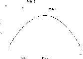
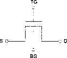
图26A是示出双栅极光电传感器10结构的剖视图。图26B是示出双栅极光电传感器10的等效电路的电路图。FIG. 26A is a cross-sectional view showing the structure of the
双栅极光电传感器10包括由非晶硅等形成的半导体薄膜11,分别形成在半导体薄膜11两端的n+硅层17和18,分别形成在n+硅层17和18上的源电极和漏电极12和13,经阻塞绝缘膜14和上部栅极绝缘膜15形成在半导体薄膜11之上的顶栅极21,配备在顶栅极21上的保护性绝缘膜20,和经下部栅极绝缘膜16配备在半导体薄膜11之下的底栅极22。双栅极光电传感器10配备在玻璃等形成的透明绝缘衬底19上。The
换句话说,双栅极光电传感器10包括由半导体薄膜11、源电极12、漏电极13和顶栅极21组成的上部MOS晶体管,和由半导体薄膜11、源电极12、漏电极13和底栅极22组成的下部MOS晶体管。如图26B的等效电路所示,双栅极光电传感器10被认为包括两个MOS晶体管,这两个MOS晶体管具有公共的由半导体薄膜11形成的沟道区、TG(顶栅极端)、BG(底栅极端)、S(源极端)和D(漏极端)。In other words, the
保护性绝缘膜20、顶栅极21、上部栅极绝缘膜15、阻塞绝缘膜14和下部栅极绝缘膜16都由具有可见光的高透射比的材料形成,该材料用于激活半导体薄膜11。从顶栅极21侧进入传感器的光穿过顶栅极21、上部栅极绝缘膜15和阻塞绝缘膜14,然后进入半导体薄膜11,从而在其中的沟道区产生并积累电荷(正空穴)。The protective
图27是示出通过二维排列双栅极光电传感器10而构成的光电传感器系统的示意图。如图27所示,光电传感器系统包括由排列成nxm矩阵的大量双栅极光电传感器10构成的传感器阵列100,分别连接在行方向的双栅极光电传感器10的顶栅极端TG和底栅极端BG的顶栅极线和底栅极线101和102,分别连接顶栅极线和底栅极线101和102的顶栅极驱动器和底栅极驱动器110和120,分别连接在列方向的双栅极光电传感器10的漏极端D的数据线103,和连接到数据线103的输出电路部分130。FIG. 27 is a schematic diagram showing a photosensor system constituted by arranging
在图27中,φtg和φbg分别表示用于产生复位脉冲φTi和读出脉冲φBi的控制信号,这将以后说明,而φpg表示用于控制施加预充电电压Vpg的定时的预充电脉冲。In FIG. 27, φtg and φbg represent control signals for generating a reset pulse φTi and a readout pulse φBi, respectively, which will be described later, and φpg represents a precharge pulse for controlling the timing of applying the precharge voltage Vpg.
在上述结构中,如下所述,光电传感功能通过从顶栅极驱动器110向顶栅极端TG施加预定电压来实现,而读出功能通过从底栅极驱动器120向底栅极端BG施加预定电压,然后经数据线103将光电传感器10的输出电压传送给输出电路部分130,并输出串行数据Vout来实现。In the above structure, as described below, the photo sensing function is realized by applying a predetermined voltage from the
图28A至28D是示出光电传感器系统的驱动控制方法以及示出传感器阵列100的第i行中的检测周期(第i行处理周期)的定时图。首先,图28A所示的高电平脉冲电压(复位脉冲;例如,Vtgh=+15V)φTi被应用给第i行的顶栅极线101,并且在复位周期Trest期间,执行用于使第i行的双栅极光电传感器10放电的复位操作。28A to 28D are timing charts showing a drive control method of the photosensor system and showing a detection cycle in the i-th row of the sensor array 100 (i-th row processing cycle). First, a high-level pulse voltage (reset pulse; for example, Vtgh=+15V) φTi shown in FIG. 28A is applied to the
随后,低电平(例如,Vtgl=-15V)的偏压φTi被施加给第i行的顶栅极线101,从而结束复位周期Trest,并启动使沟道区充电的电荷积累周期Ta。在电荷积累周期Ta期间,与从顶栅极侧进入每个传感器的光量相对应的电荷(正空穴)积累在沟道区中。Subsequently, a low level (for example, Vtgl=-15V) bias voltage φTi is applied to the
然后,和预充电电压Vpg一起示于图28C中的预充电脉冲φpg在电荷积累周期Ta期间被施加给数据线103,并且在用于使漏极13保持充电的预充电周期Tprch之后,在图28B中所示的高电平(例如,Vbgh=+10V)的偏压(读出脉冲φBi)被施加给第i行的底栅极线102。此时,双栅极光电传感器10被打开,来启动读出周期Tread。Then, the precharge pulse φpg shown in FIG. 28C together with the precharge voltage Vpg is applied to the
在读出周期Tread期间,积累在沟道区中的电荷用来缓和具有与积累在沟道区中的电荷极性相反而且施加给每个顶栅极端TG的低电平电压(例如,Vtgl=-15V)。因此,n型沟道由每个底栅极端BG处的电压Vbgh形成,在预充电电压Vpg被施加以后,数据线103处的电压VD随时间的逝去漏极电流逐渐降低。更详细地,数据线103处的电压VD的变化趋势取决于电荷积累周期Ta和所接收的光量。如图28D所示,当入射光暗淡即小量的光被接收时,电压VD趋向于逐渐降低,因此仅小量电荷被积累,而当入射光明亮即大量的光被接收时,电压VD趋向于突然降低,因此大量电荷被积累。由此可以理解,通过在读出周期Tread开始以后检测预定时段的数据线103处的电压VD,或通过检测直到电压达到预定阈电压为止所需的周期能够计算辐射量。During the read period Tread , the charges accumulated in the channel region are used to moderate the low-level voltage (for example, Vtgl) having the opposite polarity to the charges accumulated in the channel region and applied to each top gate terminal TG. =-15V). Therefore, an n-type channel is formed by the voltage Vbgh at each bottom gate terminal BG, and after the precharge voltage Vpg is applied, the voltage VD at the
图像读取是通过对传感器阵列100的每一行顺序地执行上述驱动控制,或通过在驱动脉冲不重叠的不同定时以并行的方式对每一行执行控制来实现的。Image reading is realized by sequentially performing the above-described drive control for each row of the
虽然在以述描述中,光电传感器系统采用双栅极光电传感器作为光电传感器,但是甚至是使用光电二极管或光电晶体管作为光电传感器的光电传感器系统也具有操作如下步骤:复位操作→电荷积累操作→预充电操作→读出操作,并使用类似的驱动顺序。上述的常规光电传感器系统具有以下问题。Although in the above description, the photosensor system employs a double-gate photosensor as a photosensor, even a photosensor system using a photodiode or a phototransistor as a photosensor has operations as follows: reset operation→charge accumulation operation→preset charge operation → read operation, and use a similar drive sequence. The conventional photosensor system described above has the following problems.
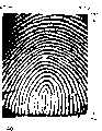
在该光电传感器系统中,这样的光电传感器阵列形成在透明衬底,例如,如上所述的玻璃衬底,的一个表面上,并且光源被提供在透明衬底的背面侧。光源所发出的光照射放置在光电传感器阵列上的被摄物体(手指等)。在读取目标图像时,与指纹等的图像图案相应的反射光被每个光电传感器接收并检测为照度信息。光电传感器阵列的图像读取操作根据在与设置的图像读取灵敏度相应的周期(用于双栅极光电传感器的电荷积累周期)期间积累在每个光电传感器中的电荷量来检测照度信息。In this photosensor system, such a photosensor array is formed on one surface of a transparent substrate, for example, a glass substrate as described above, and a light source is provided on the back side of the transparent substrate. The light emitted by the light source illuminates the subject (finger, etc.) placed on the photosensor array. When an object image is read, reflected light corresponding to an image pattern of a fingerprint or the like is received by each photosensor and detected as illuminance information. The image reading operation of the photosensor array detects illuminance information based on the amount of charge accumulated in each photosensor during a period corresponding to the set image reading sensitivity (charge accumulation period for the dual gate photosensor).
在使用上述光电传感器的光电传感器系统中,包括在使用场所,例如在室内或室外中的环境亮度的一些因素以及被摄物体的类型随着使用环境而变化。为了读取各种使用环境中的目标图像,光电传感器的图像读取灵敏度必须被适当调整。In a photoelectric sensor system using the photoelectric sensor described above, some factors including ambient brightness in a place of use, such as indoors or outdoors, and the type of object vary with the use environment. In order to read target images in various usage environments, the image reading sensitivity of the photoelectric sensor must be properly adjusted.
光电传感器的适当图像读取灵敏度随着周围条件例如环境亮度而变化。因此,在现有技术中,用于检测环境亮度的电路必须被另外配置。可选地,在正常图像读取操作开始以前,对放置在传感表面上的标准样品进行读取操作,同时读取灵敏度被改变为多个值。根据检测结果或读取结果,相应于与周围条件例如环境亮度的最佳图像读取灵敏度被获得并且被设置。但是,上述现有技术具有以下问题。The appropriate image reading sensitivity of the photosensor varies with surrounding conditions such as ambient brightness. Therefore, in the prior art, a circuit for detecting ambient brightness must be additionally configured. Optionally, before the normal image reading operation starts, the reading operation is performed on a standard sample placed on the sensing surface while the reading sensitivity is changed to a plurality of values. Based on the detection result or the reading result, an optimum image reading sensitivity corresponding to the surrounding conditions such as ambient brightness is obtained and set. However, the prior art described above has the following problems.
(1)当光电传感器系统用于指纹读取装置等时,作为被摄物体的手指(或人体)的皮肤表层的状态根据人的性别和年龄、个体差异例如身体条件、或外部环境例如温度或湿度而变化。当在正常图像读取操作开始以前根据读取操作设置图像读取灵敏度时,这阻碍了设置适当的图像读取灵敏度。因此,装置在指纹核对处理等中发生故障。(1) When the photoelectric sensor system is used in a fingerprint reading device, etc., the state of the skin surface layer of the finger (or human body) as the subject depends on the sex and age of the person, individual differences such as physical conditions, or external environments such as temperature or Humidity varies. This prevents appropriate image reading sensitivity from being set when the image reading sensitivity is set according to the reading operation before the normal image reading operation starts. Therefore, the device malfunctions in fingerprint collation processing and the like.
更详细地,如果作为被摄物体的手指的皮肤表层角质化,那么观察到的角质化指纹的脊状图形的照度高于未角质化的正常皮肤表面。由光电传感器所检测到的照度的差值变得大于初始值。如果图像读取灵敏度根据该照度信息被设置,那么图像读取灵敏度被设置为低于原来的适当值。结果,目标图像例如指纹不能被精确读取,降低了指纹的核对精确度。In more detail, if the skin surface layer of the finger as the subject is keratinized, the observed illuminance of the ridge pattern of the keratinized fingerprint is higher than that of the non-keratinized normal skin surface. The difference in illuminance detected by the photosensor becomes larger than the initial value. If the image reading sensitivity is set based on this illuminance information, the image reading sensitivity is set lower than the original appropriate value. As a result, target images such as fingerprints cannot be accurately read, lowering the collation accuracy of fingerprints.
(2)如果在正常图像读取操作以前,在读取操作中,在光电传感器元件中出现缺陷或沉积在光电传感器的传感表面上的杂质,那么直接使用包含异常值的读取结果就会导致不能设置适当的图像读取灵敏度。这阻碍了目标图像的精确读取操作。当该光电传感器系统应用于指纹读取装置时,该装置可能在指纹核对处理中发生故障。(2) If defects or impurities deposited on the sensing surface of the photosensor occur in the photosensor element during the read operation prior to the normal image read operation, then directly using the read result containing the abnormal value will As a result, appropriate image reading sensitivity cannot be set. This hinders an accurate reading operation of the target image. When the photosensor system is applied to a fingerprint reading device, the device may malfunction during fingerprint verification processing.
发明内容Contents of invention
本发明具有这样的优点,其中在具有通过二维排列多个光电传感器而构成的光电传感器阵列的光电传感器系统中,不管环境或被摄物体的个体差异如何都可设置适当的图像读取灵敏度,并且甚至在有由像素缺陷或杂质造成的异常像素数据时,也通过正常图像读取操作设置适当的图像读取灵敏度并获得高质量目标图像。The present invention has an advantage in that in a photosensor system having a photosensor array constituted by arranging a plurality of photosensors two-dimensionally, an appropriate image reading sensitivity can be set regardless of the environment or individual differences of objects to be photographed, And even when there is abnormal pixel data caused by pixel defects or impurities, an appropriate image reading sensitivity is set through normal image reading operation and a high-quality target image is obtained.
为了实现以上优点,按照本发明的光电传感器系统包括:光电传感器阵列,它通过二维排列多个光电传感器而构成,图像读取部分,它通过使用光电传感器阵列以预定图像读取灵敏度读取目标图像,灵敏度调整图像读取部分,它在光电传感器阵列中的图像读取灵敏度被改变为多个分级的同时读取灵敏度调整目标图像,最佳图像读取灵敏度得出部分,它根据与由灵敏度调整图像读取部分所读取的目标图像的图案有关的像素数据组,得出用于目标图像的读取操作的最佳图像读取灵敏度,以及图像读取灵敏度设置部分,它将最佳图像读取灵敏度设置为图像读取部分中的图像读取灵敏度。In order to achieve the above advantages, a photosensor system according to the present invention includes: a photosensor array, which is constituted by two-dimensionally arranging a plurality of photosensors, and an image reading section, which reads an object at a predetermined image reading sensitivity by using the photosensor array. Image, sensitivity adjustment image reading part, its image reading sensitivity in the photosensor array is changed to a plurality of gradations while reading the sensitivity adjustment target image, the optimum image reading sensitivity is derived part, which is based on and by the sensitivity Adjusting the pixel data set related to the pattern of the target image read by the image reading section to obtain the optimum image reading sensitivity for the reading operation of the target image, and the image reading sensitivity setting section which sets the optimum image Read Sensitivity is set to Image Read Sensitivity in the Image Read section.
该最佳图像读取灵敏度导出装置有包括以下的装置之一:The optimal image reading sensitivity deriving means includes one of the following means:
用于校正该像素数据组且然后根据该被校正的像素数据组,导出该最佳图像读取灵敏度的装置,和means for correcting the pixel data set and then deriving the optimum image read sensitivity from the corrected pixel data set, and
用于为产生该最佳图像读取灵敏度,校正该图像读取灵敏度以适合于在该像素数据组的基础上被提取的图像图案的读取操作的装置。means for correcting the image read sensitivity to be suitable for a read operation of the image pattern extracted on the basis of the pixel data set in order to produce the optimum image read sensitivity.
在一实施例中,最佳图像读取灵敏度导出装置包括图像读取灵敏度校正装置,用于根据预定周期增加率校正在该像素数据组的基础上提取的图像读取灵敏度的值。In one embodiment, the optimal image reading sensitivity deriving means includes image reading sensitivity correcting means for correcting the image reading sensitivity value extracted based on the pixel data set according to a predetermined period increase rate.
在一实施例中,最佳图像读取灵敏度导出装置包括:标准图像读取灵敏度提取装置,根据和灵敏度调整图像读取装置读取的目标图像的图案有关的每个图像读取灵敏度的像素数据组,提取标准图像读取灵敏度,校正装置,用于通过图像读取灵敏度校正装置校正标准图像读取灵敏度,和设置装置,将通过校正标准图像读取灵敏度获得的值设置为最佳图像读取灵敏度。In one embodiment, the optimal image reading sensitivity deriving means includes: standard image reading sensitivity extracting means, based on the pixel data of each image reading sensitivity related to the pattern of the target image read by the sensitivity adjustment image reading means set for extracting the standard image reading sensitivity, correction means for correcting the standard image reading sensitivity by the image reading sensitivity correcting means, and setting means for setting the value obtained by correcting the standard image reading sensitivity as an optimum image reading sensitivity.
在一实施例中,标准图像读取灵敏度提取装置包括:数据提取装置,从和灵敏度调整图像读取装置读取的目标图像的图案有关的像素数据组,提取每个图像读取灵敏度的最大和最小值;数据范围计算装置,根据像素数据组的每个图像读取灵敏度的最大和最小值计算每个图像读取灵敏度的像素数据组的数据范围,和提取装置,根据每个图像读取灵敏度的数据范围中的变化,提取标准图像读取灵敏度。In one embodiment, the standard image reading sensitivity extraction means includes: data extraction means for extracting the maximum sum of each image reading sensitivity from the pixel data set related to the pattern of the target image read by the sensitivity adjustment image reading means minimum value; data range calculation means for calculating the data range of the pixel data set of each image read sensitivity based on the maximum and minimum values of each image read sensitivity of the pixel data set, and extracting means for calculating the data range of each image read sensitivity based on each image read sensitivity Changes in the data range to extract the standard image read sensitivity.
在一实施例中,标准图像读取灵敏度提取装置包括一提取装置,用于提取具有各图像读取灵敏度数据范围中的最大数据范围的图像读取灵敏度作为标准图像读取灵敏度。In one embodiment, the standard image reading sensitivity extracting means includes an extracting means for extracting the image reading sensitivity having the largest data range among the respective image reading sensitivity data ranges as the standard image reading sensitivity.
在一实施例中,预定周期增加率是在光电传感器系统之外任意设置的。In one embodiment, the predetermined period increase rate is arbitrarily set outside the photosensor system.
在一实施例中,图像读取灵敏度校正装置比较在标准图像读取灵敏度时的像素数据组的平均值和预定参考值,并在比较结果的基础上根据预定周期增加率执行校正。In one embodiment, the image reading sensitivity correction means compares the average value of the pixel data set at the standard image reading sensitivity with a predetermined reference value, and performs correction according to a predetermined cycle increase rate based on the comparison result.
在一实施例中,该预定参考值包括在标准图像读取灵敏度时的像素数据组的数据范围的中间值。In an embodiment, the predetermined reference value includes a middle value of a data range of the pixel data set at a standard image reading sensitivity.
在一实施例中,该预定参考值是在光电传感器系统之外任意设置的。In an embodiment, the predetermined reference value is set arbitrarily outside the photoelectric sensor system.
在一实施例中,最佳图像读取灵敏度导出装置包括特定数据去除装置,用于从和灵敏度调整图像读取装置读取的目标图像图案有关的每个图像读取灵敏度的像素数据组去除特定像素数据。In one embodiment, the optimal image reading sensitivity deriving means includes specific data removing means for removing specific data from the pixel data set for each image reading sensitivity related to the target image pattern read by the sensitivity adjustment image reading means. pixel data.
在一实施例中,最佳图像读取灵敏度导出装置包括图像读取灵敏度提取装置,根据特定数据去除装置从其去除特定像素数据的像素数据组,提取适合目标图像的正常读取操作的图像读取灵敏度,和设置装置,将通过图像读取灵敏度提取装置提取的图像读取灵敏度设置为最佳图像读取灵敏度。In one embodiment, the optimal image read sensitivity deriving means includes image read sensitivity extracting means for extracting an image read suitable for normal read operation of the target image based on the pixel data set from which the specific pixel data is removed by the specific data removing means. Get the sensitivity, and set the device to set the image reading sensitivity extracted by the image reading sensitivity extraction device as the best image reading sensitivity.
在一实施例中,图像读取灵敏度提取装置包括数据提取装置,从特定数据去除装置从其去除特定像素数据的像素数据组,提取每个图像读取灵敏度的最大和最小值;数据范围计算装置,根据数据提取装置提取的像素数据组的每个图像读取灵敏度的最大和最小值,计算每个图像读取灵敏度的的像素数据组的数据范围;和提取装置,提取具有数据范围计算装置计算的各图像读取灵敏度的像素数据组数据范围中的最大数据范围的图像读取灵敏度。In one embodiment, the image reading sensitivity extraction means includes data extraction means for extracting the maximum and minimum values of each image reading sensitivity from the pixel data set from which the specific data removal means removes the specific pixel data; the data range calculation means , according to the maximum and minimum values of each image reading sensitivity of the pixel data set extracted by the data extracting means, calculate the data range of the pixel data set of each image reading sensitivity; The image read sensitivity of the maximum data range in the pixel data group data range of each image read sensitivity.
在一实施例中,特定数据去除装置从灵敏度调整读取装置对每个图像读取灵敏度获得的像素数据组中至少去除具有最大或最小值的像素数据。In one embodiment, the specific data removing means removes at least pixel data having a maximum or minimum value from the set of pixel data obtained by the sensitivity adjustment reading means for each image reading sensitivity.
在一实施例中,特定数据去除装置从灵敏度调整图像读取装置对每个图像读取灵敏度获得的像素数据组中去除自最大值开始的顺序的多个像素数据。In one embodiment, the specific data removing means removes a plurality of pixel data in order from the maximum value from the pixel data set obtained by the sensitivity adjusting image reading means for each image reading sensitivity.
在一实施例中,特定数据去除装置从灵敏度调整图像读取装置对每个图像读取灵敏度获得的像素数据组中去除自最小值开始的顺序的多个像素数据。In one embodiment, the specific data removing means removes a plurality of pixel data in order from the minimum value from the pixel data set obtained by the sensitivity adjusting image reading means for each image reading sensitivity.
在一实施例中,灵敏度调整图像读取装置仅读取在光电传感器阵列有效读取区域内事先设置的检测区域中的灵敏度调整目标图像。In one embodiment, the sensitivity adjustment image reading device only reads the sensitivity adjustment target image in the detection area set in advance in the effective reading area of the photosensor array.
在一实施例中,检测区域被设置为这样的区域,其中通过特定数据去除装置被去除了特定像素数据的像素数据组包含至少正常执行图像读取灵敏度设置装置的读取灵敏度设置操作所需的最小数目的像素数据。In one embodiment, the detection area is set as an area in which the pixel data group from which the specific pixel data has been removed by the specific data removing means contains at least the information required for normally performing the reading sensitivity setting operation of the image reading sensitivity setting means. Minimum amount of pixel data.
在一实施例中,灵敏度调整图像读取装置中的目标图像的读取操作通过设置对光电传感器阵列中预定数目的行逐步不同的图像读取灵敏度来执行。In one embodiment, the sensitivity adjustment of the reading operation of the target image in the image reading device is performed by setting image reading sensitivities stepwise different for a predetermined number of rows in the photosensor array.
在一实施例中,灵敏度调整图像读取装置读取光电传感器阵列的整个有效读取区域内的灵敏度调整目标图像。In one embodiment, the sensitivity adjustment image reading device reads the sensitivity adjustment target image in the entire effective reading area of the photosensor array.
在一实施例中,灵敏度调整图像读取装置仅读取事先在光电传感器阵列有效读取区域内设置的检测区域中的灵敏度调整目标图像。In one embodiment, the sensitivity adjustment image reading device only reads the sensitivity adjustment target image in the detection area previously set in the effective reading area of the photosensor array.
在一实施例中,像素数据包括相应于目标图像图案的亮度数据。In one embodiment, the pixel data includes brightness data corresponding to the target image pattern.
在一实施例中,光电传感器阵列的图像读取灵敏度通过调整光电传感器中的电荷积累周期来设置和控制。In one embodiment, the image read sensitivity of the photosensor array is set and controlled by adjusting the charge accumulation period in the photosensors.
在一实施例中,光电传感器具有在自半导体层形成的沟道层两侧上形成的源极和漏极,和经绝缘膜在沟道区之上和之下形成的第一和第二栅极;第一和第二栅极的任何一个被设置为光照侧;和相应于入射到光照侧上的光量的电荷在沟道区中产生和积累。In one embodiment, the photosensor has a source and a drain formed on both sides of a channel layer formed from a semiconductor layer, and first and second gates formed above and below the channel region via an insulating film. any one of the first and second gate electrodes is provided as the light-emitting side; and charges corresponding to the amount of light incident on the light-emitting side are generated and accumulated in the channel region.
为了达到以上优点,按照本发明的第一最佳图像读取灵敏度得出部分包括标准图像读取灵敏度提取部分,它根据与由灵敏度调整图像读取部分所读取的目标图像的图案有关的每个图像读取灵敏度的像素数据组,提取具有像素数据组的最大数据范围的图像读取灵敏度作为标准图像读取灵敏度,图像读取灵敏度校正部分,它根据预定周期增加率(period-increase rate)校正标准图像读取灵敏度,以及一个部分,该部分将通过校正标准图像读取灵敏度所获得的值设置为最佳图像读取灵敏度的部分。图像读取灵敏度校正部分根据对标准图像读取灵敏度的像素数据组的平均值和预定参考值进行比较的结果,唯一地或通过预定周期增加率校正标准图像读取灵敏度。In order to achieve the above advantages, the first optimum image reading sensitivity deriving section according to the present invention includes a standard image reading sensitivity extracting section which is based on each pixel data sets of image read sensitivity, extracting the image read sensitivity with the maximum data range of the pixel data set as the standard image read sensitivity, the image read sensitivity correction part, which is based on a predetermined cycle increase rate (period-increase rate) The standard image read sensitivity is corrected, and a section that sets the value obtained by correcting the standard image read sensitivity as a section of the optimum image read sensitivity. The image reading sensitivity correcting section corrects the standard image reading sensitivity uniquely or by a predetermined period increase rate based on a result of comparing the average value of the pixel data set of the standard image reading sensitivity with a predetermined reference value.
为了达到以上优点,按照本发明的第二最佳图像读取灵敏度得出部分包括特定数据去除部分,它从与由灵敏度调整图像读取部分所读取的目标图像的图案有关的每个图像读取灵敏度的像素数据组中去除特定像素数据,图像读取灵敏度提取部分,它根据特定像素数据由特定数据去除部分从其中去除的每个图像读取灵敏度的像素数据组,提取具有像素数据组的最大数据范围的图像读取灵敏度作为适于目标图像的正常读取操作的图像读取灵敏度,和设置部分,它将由图像读取灵敏度提取部分所提取的图像读取灵敏度设置为最佳图像读取灵敏度。特定数据去除部分从由灵敏度调整读取部分所获得的对于每个图像读取灵敏度的像素数据组中,去除具有最大值或最小值的像素数据或顺序地来自最大值或最小值的多个像素数据。In order to achieve the above advantages, the second optimum image reading sensitivity deriving section according to the present invention includes a specific data removing section which reads from each image related to the pattern of the target image read by the sensitivity adjusting image reading section. The specific pixel data is removed from the pixel data group for taking sensitivity, and the image reading sensitivity extracting part extracts the pixel data group having the image read sensitivity of the maximum data range as the image read sensitivity suitable for the normal read operation of the target image, and a setting section which sets the image read sensitivity extracted by the image read sensitivity extraction section as the optimum image read sensitivity. The specific data removal section removes pixel data having a maximum value or a minimum value or a plurality of pixels sequentially from the maximum value or the minimum value from the pixel data set for each image reading sensitivity obtained by the sensitivity adjustment reading section data.
按照本发明的一种光电传感器系统的驱动控制方法,其中该光电传感器系统具有通过二维排列多个光电传感器构成的光电传感器阵列,并且通过使用光电传感器阵列读取目标图像,该驱动控制方法包括:在光电传感器阵列中的图像读取灵敏度改变为多个分级的同时读取灵敏度调整目标图像;根据和从灵敏度调整目标图像读取的目标图像图案有关的像素数据组,导出适合目标图像读取操作的图像读取灵敏度;和将导出的图像读取灵敏度设置为目标图像读取操作中的读取灵敏度,该导出适合目标图像读取操作的图像读取灵敏度的步骤包括有以下步骤之一:校正该像素数据组且然后根据该被校正的像素数据组,导出一最佳图像读取灵敏度,和为产生该最佳图像读取灵敏度,校正该图像读取灵敏度以适合于在该像素数据组的基础上被提取的图像图案的读取操作。A drive control method of a photoelectric sensor system according to the present invention, wherein the photosensor system has a photosensor array constituted by two-dimensionally arranging a plurality of photosensors, and by using the photosensor array to read an object image, the drive control method includes : read sensitivity adjustment target image while image reading sensitivity in photosensor array is changed into multiple gradations; derive suitable target image reading based on pixel data set related to target image pattern read from sensitivity adjustment target image The image reading sensitivity of the operation; and setting the derived image reading sensitivity as the reading sensitivity in the target image reading operation, the step of deriving the image reading sensitivity suitable for the target image reading operation includes one of the following steps: correcting the pixel data set and then deriving an optimum image read sensitivity based on the corrected pixel data set, and to generate the optimum image read sensitivity, correcting the image read sensitivity to be suitable for the pixel data set A read operation based on the extracted image pattern.
在一实施例中,适合目标图像读取操作的图像读取灵敏度的导出包括根据预定周期增加率校正图像读取灵敏度的值。In an embodiment, the derivation of the image reading sensitivity suitable for the target image reading operation includes correcting the value of the image reading sensitivity according to a predetermined period increase rate.
在一实施例中,适合目标图像读取操作的图像读取灵敏度的导出包括根据和通过灵敏度调整目标图像的读取而读取的目标图像图案有关的像素数据组,提取标准图像读取灵敏度;根据预定周期增加率校正标准图像读取灵敏度;和将通过校正标准图像读取灵敏度获得的值设置为适合目标图像读取操作的图像读取灵敏度。In one embodiment, the derivation of the image reading sensitivity suitable for the target image reading operation includes extracting a standard image reading sensitivity based on a pixel data set related to the target image pattern read by the reading of the sensitivity-adjusted target image; correcting the standard image reading sensitivity according to a predetermined period increase rate; and setting a value obtained by correcting the standard image reading sensitivity as an image reading sensitivity suitable for a target image reading operation.
在一实施例中,标准图像读取灵敏度的提取包括:从和通过灵敏度调整目标图像的读取而读取的目标图像图案有关的像素数据组,提取每个图像读取灵敏度的最大和最小值;根据为每个图像读取灵敏度提取的像素数据组的最大和最小值,计算每个图像读取灵敏度的像素数据组的数据范围;和根据每个图像读取灵敏度的数据范围中的变化,提取标准图像读取灵敏度。In one embodiment, the extraction of the standard image reading sensitivity includes: extracting the maximum and minimum values of each image reading sensitivity from the pixel data set related to the target image pattern read by the reading of the sensitivity-adjusted target image ; calculating the data range of the pixel data set for each image read sensitivity based on the maximum and minimum values of the pixel data set extracted for each image read sensitivity; and according to the change in the data range of each image read sensitivity, Extract the standard image read sensitivity.
在一实施例中,提取标准图像读取灵敏度包括比较各图像读取灵敏度的数据范围并提取具有最大数据范围的图像读取灵敏度作为标准图像读取灵敏度。In one embodiment, extracting the standard image reading sensitivity includes comparing the data ranges of the image reading sensitivities and extracting the image reading sensitivity with the largest data range as the standard image reading sensitivity.
在一实施例中,该预定周期增加率是在光电传感器系统之外任意设置的。In one embodiment, the predetermined period increase rate is arbitrarily set outside the photosensor system.
在一实施例中,根据预定周期增加率校正图像读取灵敏度在比较标准图像读取灵敏度时的像素数据组的平均值和预定参考值的结果的基础上执行。In one embodiment, the correction of the image reading sensitivity according to the predetermined period increase rate is performed on the basis of the result of comparing the average value of the pixel data set at the standard image reading sensitivity with a predetermined reference value.
在一实施例中,该预定参考值包括标准图像读取灵敏度时的像素数据的数据范围的中间值。In one embodiment, the predetermined reference value includes the middle value of the data range of the pixel data at the standard image reading sensitivity.
在一实施例中,该预定参考值是在光电传感器系统之外任意设置的。In an embodiment, the predetermined reference value is set arbitrarily outside the photoelectric sensor system.
在一实施例中,导出适合目标图像读取操作的图像读取灵敏度包括从和通过灵敏度调整目标图像的读取而读取的目标图像图案有关的每个图像读取灵敏度的像素数据组,去除特定像素数据。In one embodiment, deriving the image reading sensitivity suitable for the target image reading operation includes, from the pixel data set for each image reading sensitivity related to the target image pattern read by the reading of the sensitivity-adjusted target image, removing specific pixel data.
在一实施例中,导出适合目标图像读取操作的图像读取灵敏度包括去除特定像素数据,并根据自从其去除特定像素数据的像素数据组提取适合目标图像正常读取操作的图像读取灵敏度。In one embodiment, deriving an image reading sensitivity suitable for a target image reading operation includes removing specific pixel data, and extracting an image reading sensitivity suitable for a normal reading operation of a target image based on a pixel data set from which the specific pixel data is removed.
在一实施例中,提取适合目标图像正常读取操作的图像读取灵敏度包括去除特定像素数据,并自从其去除特定像素数据的像素数据组提取每个图像读取灵敏度的最大和最小值;根据对每个图像读取灵敏度提取的像素数据组的最大和最小值,计算每个图像读取灵敏度的像素数据组的数据范围;和提取具有各图像读取灵敏度的像素数据组的数据范围中的最大数据范围的图像读取灵敏度。According to calculating the maximum and minimum values of the pixel data sets extracted for each image read sensitivity, calculating the data range of the pixel data set for each image read sensitivity; and extracting the Image read sensitivity for maximum data range.
在一实施例中,去除特定像素数据包括从对每个图像读取灵敏度获得的像素数据组至少去除具有最大或最小值的像素数据。In an embodiment, removing specific pixel data includes removing at least pixel data having a maximum or minimum value from the set of pixel data obtained for each image read sensitivity.
在一实施例中,去除特定像素数据包括:比较包含在每个图像读取灵敏度的像素数据组中的所有像素数据的大小并排序像素数据的处理;和从排序的像素数据串的任一端进行去除预定数目的像素数据的处理。In one embodiment, removing specific pixel data includes: comparing the size of all pixel data contained in the pixel data set for each image read sensitivity and sorting the pixel data; and proceeding from either end of the sorted pixel data string A process of removing a predetermined number of pixel data.
在一实施例中,去除特定数据包括以预定次数重复进行比较包含在每个图像读取灵敏度的像素数据组中的所有像素数据的大小,并提取和去除具有最大或最小值的像素数据。In one embodiment, removing the specific data includes repeating, a predetermined number of times, comparing the sizes of all pixel data included in the pixel data set for each image read sensitivity, and extracting and removing pixel data having a maximum or minimum value.
在一实施例中,读取灵敏度调整目标图像包括设置对光电传感器阵列中预定数目的行逐步不同的图像读取灵敏度。In one embodiment, reading the sensitivity adjustment target image includes setting a stepwise different image reading sensitivity for a predetermined number of rows in the photosensor array.
在一实施例中,像素数据包括相应于目标图像图案的亮度数据。In one embodiment, the pixel data includes brightness data corresponding to the target image pattern.
在一实施例中,光电传感器阵列的图像读取灵敏度通过调整光电传感器中的电荷积累周期来设置和控制。In one embodiment, the image read sensitivity of the photosensor array is set and controlled by adjusting the charge accumulation period in the photosensors.
在一实施例中,光电传感器具有经自半导体层形成的沟道层形成的源极和漏极,和经绝缘膜至少在沟道区之上和之下形成的第一和第二栅极;第一和第二栅极的任何一个被设置为光照侧;和相应于从光照侧进入的光量的电荷在沟道区中产生和积累。In one embodiment, the photosensor has a source electrode and a drain electrode formed through a channel layer formed from a semiconductor layer, and first and second gate electrodes formed at least above and below the channel region through an insulating film; Either one of the first and second gate electrodes is provided as the light-emitting side; and charges corresponding to the amount of light entering from the light-emitting side are generated and accumulated in the channel region.
即使被摄物体的个体差异或外部环境改变,或者像素数据包含异常值,也能够避免这些对适当设置图像读取灵敏度和获得高质量目标图像的影响。Even if there are individual differences in subjects or changes in the external environment, or pixel data contains abnormal values, these influences on properly setting image read sensitivity and obtaining high-quality target images can be avoided.
发明另外的优点将在以下的描述中提出,并且将通过描述而部地明显,或者可以通过发明的应用实践而了解。发明的优点可以通过在下文中特别指出的手段和组合来实现和获得。Additional advantages of the invention will be set forth in the description which follows and will be partly apparent from the description, or may be learned by practice of the invention. The advantages of the invention can be realized and obtained by means of the instrumentalities and combinations particularly pointed out hereinafter.
附图说明Description of drawings
结合并构成说明书一部分的相应附图说明了发明的实施例,并和以上给出的概述和下面给出的实施例详述一起,用于解释发明的原理。The accompanying drawings, which are incorporated in and constitute a part of the specification, illustrate embodiments of the invention and, together with the General Description given above and the Detailed Description of the Embodiments given below, serve to explain the principles of the invention.
图1是示出按照本发明第一实施例的光电传感器系统配置的框图;FIG. 1 is a block diagram showing the configuration of a photosensor system according to a first embodiment of the present invention;
图2是示出应用于第一实施例的控制器配置的框图;FIG. 2 is a block diagram showing a controller configuration applied to the first embodiment;
图3是示出按照第一实施例由控制器执行的灵敏度调整/设置处理示例的流程图;3 is a flowchart showing an example of sensitivity adjustment/setting processing performed by the controller according to the first embodiment;
图4是示出第一实施例中指纹图像被读取时的图像数据示例的图;FIG. 4 is a diagram showing an example of image data when a fingerprint image is read in the first embodiment;
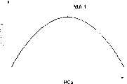
图5A-5E是示出第一实施例中通过灵敏度调整读取操作所获得的指纹图像数据中各行的亮度数据的变化的曲线图;5A-5E are graphs showing changes in luminance data for each row in fingerprint image data obtained by a sensitivity adjustment reading operation in the first embodiment;
图6A和6B是示出第一实施例中通过灵敏度调整读取操作所获得的各行的亮度数据的动态范围与行号之间的关系的表格及行号对图像读取灵敏度的对应表;6A and 6B are tables showing the relationship between the dynamic range of the luminance data of each row obtained through the sensitivity adjustment reading operation and the row number in the first embodiment and the correspondence table of the row number to the image reading sensitivity;
图7A和7B是示出指纹图像的图,和示出第一实施例中在没有执行周期增加校正处理所获得的图像读取灵敏度来执行正常图像读取操作时,在一图像读取灵敏度下的各列的亮度数据的变化的示例的曲线图;7A and 7B are diagrams showing fingerprint images, and show that in the first embodiment, when a normal image reading operation is performed without performing the image reading sensitivity obtained by cycle increase correction processing, at an image reading sensitivity A graph of an example of changes in brightness data for each column;
图8A和8B是示出指纹图像的图,和示出第一实施例中以通过执行周期增加校正处理所获得的图像读取灵敏度来执行正常图像读取操作时,在一图像读取灵敏度下的各列的亮度数据的变化的示例的曲线图;8A and 8B are diagrams showing fingerprint images, and show that in the first embodiment, when a normal image reading operation is performed with an image reading sensitivity obtained by performing cycle increase correction processing, at an image reading sensitivity A graph of an example of changes in brightness data for each column;
图9是示出应用于第二实施例的控制器的配置的框图;FIG. 9 is a block diagram showing the configuration of a controller applied to the second embodiment;
图10是示出按照第二实施例由控制器所执行的灵敏度调整/设置处理的示例的流程图;10 is a flowchart showing an example of sensitivity adjustment/setting processing performed by the controller according to the second embodiment;
图11是示出按照本发明第三实施例的光电传感器系统的配置的框图;11 is a block diagram showing the configuration of a photosensor system according to a third embodiment of the present invention;
图12是示出应用于第三实施例的控制器的配置的框图;FIG. 12 is a block diagram showing the configuration of a controller applied to the third embodiment;
图13是示出按照第三实施例由控制器所执行的灵敏度调整/设置处理的示例的流程图;13 is a flowchart showing an example of sensitivity adjustment/setting processing performed by the controller according to the third embodiment;
图14A和14B是示出按照第三实施例的灵敏度调整读取操作中的读取操作的目标区域及示例的概念视图;14A and 14B are conceptual views showing target areas and examples of a reading operation in a sensitivity adjustment reading operation according to the third embodiment;
图15A和15B是示出按照第三实施例的灵敏度调整读取操作中的读取操作的另一个目标区域和另一个示例的概念视图;15A and 15B are conceptual views showing another target area and another example of a reading operation in a sensitivity adjustment reading operation according to the third embodiment;
图16A-16D是示出应用于第三实施例的特定像素数据去除操作方法的示例的概念视图;16A-16D are conceptual views showing an example of a specific pixel data removal operation method applied to the third embodiment;
图17A和17B是示出第三实施例中的光电传感器阵列的预定检测区域,和存在异常像素时由灵敏度调整读取操作在检测区域内所读取的指纹图像的示例的图;17A and 17B are diagrams showing a predetermined detection area of the photosensor array in the third embodiment, and an example of a fingerprint image read within the detection area by a sensitivity adjustment reading operation when abnormal pixels exist;
图18A-18E是示出存在异常像素时在第三实施例中通过灵敏度调整读取操作所获得的对于指纹图像数据的各行的亮度数据中变化的示例的曲线图;18A-18E are graphs showing examples of changes in luminance data for each row of fingerprint image data obtained by a sensitivity adjustment reading operation in the third embodiment when abnormal pixels exist;
图19A和19B是示出存在异常像素时通过灵敏度调整读取操作所获得的指纹图像数据的各行的亮度数据动态范围与行号之间的曲线图和表格及行号对图像读取灵敏度的对应表;19A and 19B are graphs and tables showing the relationship between the dynamic range of luminance data and the row number of each row of fingerprint image data obtained by the sensitivity adjustment reading operation when there are abnormal pixels, and the correspondence of the row number to the image reading sensitivity surface;
图20A和20B是示出使用包括异常像素的光电传感器阵列,在设置图像读取灵敏度中不应用和应用按照第三实施例的灵敏度设置方法时的指纹图案示例的图;20A and 20B are diagrams showing examples of fingerprint patterns when the sensitivity setting method according to the third embodiment is not applied and applied in setting image reading sensitivity using a photosensor array including abnormal pixels;
图21A-21E是示出第三实施例中通过特定像素数据去除操作所获得的对于各行指纹图像数据的亮度数据的变化的示例的曲线图;21A-21E are graphs showing examples of changes in luminance data for each row of fingerprint image data obtained by specific pixel data removal operations in the third embodiment;
图22A和22B是示出在第三实施例中通过对存在异常像素时由灵敏度调整读取操作所获得的指纹图像数据执行特定像素数据去除操作而获得的各行的亮度数据的动态范围与行号之间的关系的示例的曲线图和表格,及行号对图像读取灵敏度的对应表;22A and 22B are graphs showing the dynamic range and row number of luminance data of each row obtained by performing a specific pixel data removal operation on fingerprint image data obtained by a sensitivity adjustment reading operation when abnormal pixels exist in the third embodiment The graph and table of the example of the relationship between, and the corresponding table of line number to image reading sensitivity;
图23A-23J是示出适用于按照本发明的光电传感器系统的图像读取操作的驱动控制方法示例的定时图;23A-23J are timing charts showing an example of a drive control method suitable for an image reading operation of the photosensor system according to the present invention;
图24A-24J是示出适用于每个实施例中的灵敏度调整读取操作的图像读取灵敏度设置方法的第一示例的定时图;24A-24J are timing charts showing a first example of an image reading sensitivity setting method applicable to a sensitivity adjustment reading operation in each embodiment;
图25A-25J是示出适用于每个实施例中的灵敏度调整读取操作的图像读取灵敏度设置方法的第二示例的定时图;25A-25J are timing charts showing a second example of the image reading sensitivity setting method applicable to the sensitivity adjustment reading operation in each embodiment;
图26A是示出双栅极光电传感器的结构的截面图;26A is a cross-sectional view showing the structure of a dual-gate photosensor;
图26B是示出双栅极光电传感器的等效电路的电路图;26B is a circuit diagram showing an equivalent circuit of a dual-gate photosensor;
图27是示出通过二维排列双栅极光电传感器所构成的光电传感器系统的示意图;和27 is a schematic diagram showing a photosensor system formed by two-dimensionally arranging double-gate photosensors; and
图28A-28D是示出双栅极光电传感器系统的驱动控制方法的定时图。28A-28D are timing charts illustrating a driving control method of a dual-gate photosensor system.
具体实施方式 Detailed ways
按照本发明的光电传感器系统和其驱动控制方法的详细说明将根据示于几个附图中的实施例来描述。在下述实施例中,双栅极光电传感器被用为光电传感器。但是本发明的配置不限于双栅极光电传感器,它还可应用于使用其它类型的光电传感器的光电传感器系统。A detailed description of the photosensor system and its drive control method according to the present invention will be described based on the embodiments shown in several drawings. In the following embodiments, a double gate photosensor is used as the photosensor. But the configuration of the present invention is not limited to the dual-gate photosensor, and it can also be applied to photosensor systems using other types of photosensors.
上述发明内容中所述的“图像读取部分”对应于图1所示的光电传感器阵列100、顶栅极驱动器110、底栅极驱动器120、输出电路部分130、模/数转换器140。The "image reading section" described in the above summary corresponds to the
上述发明内容中所述的“灵敏度调整图像读取装置”对应于图2、9、12所示的主控制器153、数据控制器152、灵敏度设置寄存器159。The "sensitivity adjustment image reading device" described in the above summary of the invention corresponds to the
上述发明内容中所述的“最佳图像读取灵敏度导出装置”对应于图2、9、12所示的漏极驱动器130、数据比较器154、数据选择器156、RAM 160。The "optimum image reading sensitivity derivation device" described in the above summary of the invention corresponds to the
上述发明内容中所述的“图像灵敏度设置装置”对应于图2、9、12所示的灵敏度设置寄存器159。The “image sensitivity setting device” described in the above summary of the invention corresponds to the
上述发明内容中所述的“标准图像读取灵敏度提取装置”,对应于图2、9、12所示的数据比较器154、加法器155、数据选择器156。The "standard image reading sensitivity extraction device" described in the above summary of the invention corresponds to the
上述发明内容中所述的“校正装置”对应于图2、9所示的周期增加寄存器157。The “correcting means” described in the above summary of the invention corresponds to the
上述发明内容中所述的“设置装置”对应于图2、9、12所示的灵敏度设置寄存器159。The “setting means” described in the above summary of the invention corresponds to the
上述发明内容中所述的“数据提取装置”对应于图2、9、12所示的数据控制器152、数据比较器154、加法器155。The "data extraction device" described in the above summary of the invention corresponds to the
上述发明内容中所述的“数据范围计算装置”对应于图2、9、12所示的加法器155、数据选择器156和RAM 160。The "data range computing device" described in the above-mentioned summary of the invention corresponds to the
上述发明内容中所述的“特定数据去除装置”对应于图12中的数据比较器154、RAM 160。The "specific data removal device" described in the above summary of the invention corresponds to the
上述发明内容中所述的“图像读取灵敏度提取装置”对应于图12中所示的数据控制器152、数据选择器156、数据比较器154、加法器155、RAM 160。The "image reading sensitivity extraction means" described in the above summary of the invention corresponds to the
<第一实施例><First embodiment>
按照本发明的光电传感器系统的第一实施例将参照几个附图说明。A first embodiment of a photoelectric sensor system according to the invention will be described with reference to several drawings.
图1是示出按照第一实施例的光电传感器系统配置的框图。图26A所示的双栅极光电传感器被用作光电传感器,并且如果必要的话将参考图27所示的光电传感器系统的配置。与图27所示的光电传感器系统中相同的参考号表示相同的部分,并且其说明将被简化或省略。FIG. 1 is a block diagram showing the configuration of a photosensor system according to a first embodiment. A double gate photosensor shown in FIG. 26A is used as a photosensor, and the configuration of the photosensor system shown in FIG. 27 will be referred to if necessary. The same reference numerals as in the photosensor system shown in FIG. 27 denote the same parts, and descriptions thereof will be simplified or omitted.
如图1所示,按照该实施例的光电传感器系统包括光电传感器阵列100,光电传感器阵列100包括图26A所示的二维排列的双栅极光电传感器10;顶栅极驱动器110,用于在预定定时将预定复位脉冲施加给每个双栅极光电传感器10的顶栅极TG(图27);底栅极驱动器120,用于在预定定时将预定读出脉冲施加给每个双栅极光电传感器10的底栅极BG;输出电路部分130,其具有列开关131、预充电开关132和放大器133,用于将预充电电压施加给双栅极光电传感器10并读出数据线电压;模/数转换器(在下文中称为A/D转换器)140,用于将读出的模拟信号的数据电压转换为数字信号的图像数据;控制器150,它被用来控制由光电传感器阵列100读取目标图像的操作以及与外部功能部分200交换数据,并且它在第一实施例中控制灵敏度设置;以及RAM160,用于临时存储所获得的图像数据(像素数据组)以及处理与灵敏度设置处理(下面要说明的)有关的数据等。As shown in FIG. 1, the photosensor system according to this embodiment includes a
光电传感器阵列100、顶栅极驱动器110、底栅极驱动器120和输出电路部分130的结构与图27所示的光电传感器系统的相同并具有相同的功能。除这些部件外,该实施例采用A/D转换器140、控制器150和RAM160来实现如下所述的各种控制。The structure of the
控制器150将预定控制信号φtg和φbg分别输出给顶栅极驱动器和底栅极驱动器110和120,它们依次分别向构成光电传感器阵列100的双栅极光电传感器10的顶栅极TG和底栅极BG输出预定电压(复位脉冲φTi和读出脉冲φBi)。控制器150还向预充电开关132输出预定控制信号φpg以将预充电电压Vpg施加给双栅极光电传感器10的漏极端D。控制器150控制检测与积累在双栅极光电传感器10中的电荷量相对应的漏极电压VD的操作,所积累的电荷量与所读取的被摄物体的图案相对应。由漏极驱动器130所读出的输出电压Vout经A/D转换器140转换为数字信号,并且该数字信号被作为图像输出信号输入给控制器150。控制器150具有对图像输出信号执行预定图像处理的功能及将所处理的信号写入RAM160或从RAM160中读出的功能。控制器150还用作与执行预定处理例如图像数据识别、修改等的外部功能部分200连接的接口。The
控制器150具有另一种功能:改变和控制将要输出给顶栅极驱动器和底栅极驱动器110和120的控制信号,来根据周围环境例如外部光照度设置用于读取目标图像的最佳读取灵敏度,即用于双栅极光电传感器10的最佳电荷积累周期。The
外部功能部分200具有对例如根据光电传感器系统的应用目的由光电传感器系统所获得的图像数据执行图像处理(核对、修改等)的功能。外部功能部分200还具有监视光电传感器系统或控制器150的工作状态的功能及输出计算处理结果等的功能。此外,外部功能部分200还用作为输入/输出接口,用于输入和设置各种参数,例如电荷积累周期Ta的缺省值,和周期增加率及平均比较值(以后要说明),以便定义操作状态、计算处理等。The
应用于上述光电传感器系统的控制器的详细配置和操作将参考几个附图说明。The detailed configuration and operation of the controller applied to the photoelectric sensor system described above will be described with reference to several drawings.
图2是示出按照第一实施例应用于光电传感器系统的控制器配置的框图。Fig. 2 is a block diagram showing the configuration of a controller applied to the photosensor system according to the first embodiment.
如图2所示,该实施例中的控制器150包括装置控制器151,该装置控制器151用于控制顶栅极驱动器110、底栅极驱动器120和预充电开关132的操作;数据控制器152,用于管理各种数据例如给RAM160的图像数据、写入数据和读出数据;和主控制器153,它监督控制器151和152并与外部功能部分200接口连接。As shown in Figure 2, the
控制器150进一步包括:数据比较器154,用于根据经A/D转换器140从光电传感器阵列100作为数字信号输入的图像数据,通过比较包含在图像输出信号中的像素数据中的亮度数据的大小来提取最大和最小值,并用于从计算的动态范围提取最大动态范围;加法器155,用于从由数据比较器154所提取的像素数据的最大和最小值之间的差值计算动态范围(数据范围);数据选择器156,用于接收图像数据及处理经A/D转换器140、数据比较器154和加法器155所处理的数据,并进行这些数据的写入/读出RAM160、这些数据重新输入到数据比较器154和加法器155与必要时经数据控制器152将这些数据输出给外部功能部分200之间切换;周期增加寄存器157,它保持有用于由主控制器153对图像读取灵敏度执行周期增加校正(以后说明)的周期增加率,其中的图像读取灵敏度是由数据比较器154、加法器155和数据选择器156所提取的并对应于最大动态范围;以及灵敏度设置寄存器159,用于基于已经经过周期增加校正的图像读取灵敏度(最佳图像读取灵敏度),根据从数据控制器152所输出的控制信号来设置从装置控制器151输出给顶栅极驱动器和底栅极驱动器110和120的控制信号φtg和φbg的定时。The
由上述控制器进行的处理操作将参考几个图来说明。The processing operations performed by the above controller will be explained with reference to several figures.
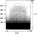
图3是示出按照第一实施例由应用于光电传感器系统的控制器所执行的灵敏度调整/设置处理示例的流程图。图4是示出在按照该实施例的光电传感器系统应用于指纹读取装置时,并且在应用于灵敏度调整处理的灵敏度调整读取操作中逐行地改变传感器阵列的图像读取灵敏度的同时读取指纹时的指纹图像数据示例的图。图5A-5E是示出通过灵敏度调整读取操作所获得的指纹图像数据中各行亮度数据中的变化的曲线图。图6A和6B是示出通过灵敏度调整读取操作所获得的各行亮度数据的动态范围(数据范围)和行号与图像读取灵敏度对应表之间的关系的表格。处理操作将参照图1和图2所示的光电传感器系统的配置来解释。对于各种数据例如亮度数据、其动态范围及电荷积累周期,仅仅具有代表性的第80、104、128、152和176行的数据被图示说明。3 is a flowchart showing an example of sensitivity adjustment/setting processing performed by the controller applied to the photosensor system according to the first embodiment. 4 is a diagram showing simultaneous reading while changing the image reading sensitivity of the sensor array line by line in the sensitivity adjustment reading operation applied to the sensitivity adjustment process when the photosensor system according to this embodiment is applied to a fingerprint reading device. A diagram of an example of fingerprint image data at the time of fingerprinting. 5A-5E are graphs showing changes in luminance data for each row in fingerprint image data obtained through a sensitivity adjustment reading operation. 6A and 6B are tables showing the relationship between the dynamic range (data range) of luminance data of each line obtained by the sensitivity adjustment reading operation and the line number and the image reading sensitivity correspondence table. Processing operations will be explained with reference to the configuration of the photosensor system shown in FIGS. 1 and 2 . For various data such as luminance data, its dynamic range, and charge accumulation period, only representative data of
(步骤S11)(step S11)
如图3所示,主控制器153在目标图像的正常读取操作之前开始灵敏度调整读取操作。主控制器153经数据控制器152控制灵敏度设置寄存器159为灵敏度调整读取操作设置图像读取灵敏度。为了灵敏度调整的目的,主控制器153读取目标图像。As shown in FIG. 3, the
通常,该灵敏度调整读取操作在正常图像读取操作以前被立即执行。但是,灵敏度调整读取操作不一定是在正常图像读取操作之前的定时执行,而可以在和正常图像读取操作不同的定时独立地执行,例如,当图像读取灵敏度必须被设置时。Usually, this sensitivity adjustment reading operation is performed immediately before the normal image reading operation. However, the sensitivity adjustment reading operation is not necessarily performed at a timing prior to the normal image reading operation, but may be independently performed at a timing different from the normal image reading operation, for example, when the image reading sensitivity has to be set.
类似于正常图像读取操作,灵敏度调整读取操作通过对构成光电传感器阵列的双栅极光电传感器执行以下一系列处理来实现:复位操作→电荷积累操作→预充电操作→读取操作。此时,通过在预定定时对各行重复执行预充电操作和读取操作来逐步地改变电荷积累周期,从而对如图4所示的其中双栅极光电传感器排列成256行x196列的矩阵的光电传感器阵列100中较大的行号设置较高的图像读取灵敏度。对各行以不同的图像读取灵敏度所读取的图像数据通过目标图像的一个读取操作来获得。对于每行的图像读取灵敏度以表(行号对图像读取灵敏度的对应表)的形式与行号相对应地存储在RAM160中。对较大的行号设置较长的电荷积累周期和较高的图像读取灵敏度。指纹的脊状/谷形的图形被读取为淡的(浅的)图像或在外部光的影响下几乎不可见的明亮图像(图4中的上边)。另一方面,对较小的行号设置较短的电荷积累周期和较低的图像读取灵敏度。指纹的脊状/谷形的图形被读取为稍黑的图像或几乎不可见的暗黑图像(图4中的下边)。注意,在灵敏度调整读取操作中设置图像读取灵敏度的详细方法将在以后说明。Similar to the normal image reading operation, the sensitivity adjustment reading operation is realized by performing the following series of processing on the dual-gate photosensors constituting the photosensor array: reset operation→charge accumulation operation→precharge operation→read operation. At this time, the charge accumulation period is gradually changed by repeatedly performing the precharge operation and the read operation for each row at a predetermined timing, so that for a photoelectric sensor in which double-gate photosensors are arranged in a matrix of 256 rows by 196 columns as shown in FIG. A larger row number in the
在该实施例中,改变在灵敏度调整读取操作中的每行光电传感器阵列的图像读取灵敏度。本发明不限于此,图像读取灵敏度可以逐步地例如每多行地改变。可选地,每当图像读取灵敏度被改变时,可以读取光电传感器阵列的一帧的目标图像。简而言之,对一个被摄物体,图像数据能够以不同图像读取灵敏度来获得。In this embodiment, the image reading sensitivity of each row of the photosensor array in the sensitivity adjustment reading operation is changed. The present invention is not limited thereto, and the image reading sensitivity may be changed stepwise, for example, every multiple lines. Alternatively, one frame of the target image of the photosensor array may be read every time the image reading sensitivity is changed. In short, image data can be obtained with different image reading sensitivities for one subject.
(步骤S12)(step S12)
通过上述灵敏度调整读取操作所读取的图像数据经漏极驱动器130的放大器133和A/D转换器140转换为数字信号。该数字信号被输入给数据比较器154作为与目标图像的明/暗图案相对应的每个图像读取灵敏度的像素数据(亮度数据)。The image data read by the above-described sensitivity adjustment reading operation is converted into a digital signal through the
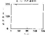
更详细地,如图5A-5E所示,在被摄物体上的白和黑之间设置256个灰度级。图4所示光电传感器阵列100中例如第176、152、128、104和80行的漏极电压VD的电压变化被转换为0-255范围内的亮度数据值,这用曲线图表示。如图5A所示,在第176行中,灵敏度设置得高,从而亮度数据基本上收敛到上限(255),并且几乎没有提供任何作为图像数据的信息。如图5B所示,在152行中,灵敏度设置得相对高,在有些列上亮度数据达到上限,并且所有图像数据的脊状/谷形(明/暗)图形不能被读取。In more detail, as shown in FIGS. 5A-5E , 256 gray levels are set between white and black on the subject. The voltage variation of the drain voltage VD in the
如图5C所示,相反地,在第128行中,在所有列上亮度数据即达不到上限(255)也达不到下限(0),而分布在上、下限之间。如图5D所示,在第104行中,灵敏度设置得相对低,亮度数据分布在上、下限之间。但是,在有些列上亮度数据达到下限,并且所有图像数据的脊状/谷形图形不能被读取。如图5E所示,在第80行中,灵敏度设置得低,从而亮度数据基本上收敛于下限并且几乎不能提供任何作为图像数据的信息。As shown in FIG. 5C , on the contrary, in the 128th row, the luminance data does not reach the upper limit (255) or the lower limit (0) in all columns, but is distributed between the upper limit and the lower limit. As shown in FIG. 5D, in
(步骤S13和S14)(steps S13 and S14)
对于每个图像读取灵敏度,表示最大值的亮度数据(最高灰度级的像素)和表示最小值的亮度数据(最低灰度级的像素)从输入给数据比较器154的亮度数据中提取,并且输出给加法器155。For each image reading sensitivity, luminance data representing the maximum value (pixel of the highest gray scale) and luminance data representing the minimum value (pixel of the lowest gray scale) are extracted from the luminance data input to the
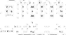
如图6A所示,对于每一行,表示最大值的亮度数据(最高灰度级的像素)和表示最小值的亮度数据(最低灰度级的像素)从输入给数据比较器154的亮度数据中提取,并且输出给加法器155。As shown in FIG. 6A, for each row, luminance data representing a maximum value (pixel of the highest grayscale) and luminance data representing a minimum value (pixel of the lowest grayscale) are selected from the luminance data input to the
加法器155计算每行的亮度数据的最大和最小值之间的差,从而获得每个图像读取灵敏度的动态范围。加法器155经数据选择器156在RAM160中存储动态范围。加法器155对所有行或预定数目的行执行动态范围计算处理。The
(步骤S15)(step S15)
存储在RAM160中的各图像读取灵敏度的动态范围经数据选择器156读出,并输入给数据比较器154。数据比较器154从各图像读取灵敏度的动态范围中提取最大值。The dynamic range of each image reading sensitivity stored in
更详细地,最大和最小值根据图5A-5E所示的各行亮度数据中的分布变化被提取作为数字数据。动态范围从最大和最小值之间的差计算。如图6A所示,数据范围取决于第176行和第152行中的最小值,因为亮度数据达到上限而且其最大值固定为255。在第104行和第80行中,数据范围取决于最大值,因为亮度数据达到下限并且其最小值固定为0。In more detail, the maximum and minimum values are extracted as digital data according to distribution changes in the luminance data of each line shown in FIGS. 5A-5E . Dynamic range is calculated from the difference between the maximum and minimum values. As shown in FIG. 6A, the data range depends on the minimum value in the 176th line and the 152nd line, because the luminance data reaches the upper limit and its maximum value is fixed at 255. In
在第128行中,动态范围取决于亮度数据的最大和最小值之间的差,因为亮度数据既没有达到上限或也没有达到下限。第128行提供比第176、152、104和80行大的数据范围。换句话说,第128行的亮度数据是具有与指纹脊状/谷形图形相应的良好对比度的图像数据,并且最佳图像读取灵敏度能够被确切地设置。In
(步骤S16)(step S16)
相应于最大动态范围的图像读取灵敏度被提取并被设置为标准图像读取灵敏度。The image read sensitivity corresponding to the maximum dynamic range is extracted and set as the standard image read sensitivity.
更详细地,如图6B所示,为第128行设置的图像读取灵敏度,即根据在动态范围取最大值处的行号(第128行)通过查找存储在RAM160中的行号与图像读取灵敏度对应表来提取双栅极光电传感器的电荷积累周期T128。In more detail, as shown in FIG. 6B , the image reading sensitivity set for the 128th row, that is, according to the row number (the 128th row) where the dynamic range takes the maximum value, is stored in the
(步骤S17)(step S17)
主控制器153控制数据控制器152,从而根据在周期增加寄存器157中事先设置的预定周期增加率执行校正图像读取灵敏度(标准图像读取灵敏度)的处理。The
例如,为第128行设置的并且呈现最大动态范围的图像读取灵敏度对应于电荷积累周期T128=91.2ms,在周期增加寄存器157中事先设置的周期增加率为32%。在这种情况中,用于灵敏度设置寄存器159的重写的电荷积累周期是周期增加32%的数值:For example, the image reading sensitivity set for the 128th row and exhibiting the maximum dynamic range corresponds to the charge accumulation period T128 =91.2 ms, and the period increase rate previously set in the
91.2×(1+0.32)120ms…(2)91.2×(1+0.32)120ms...(2)
该周期增加校正处理以1.32倍增加在步骤S16中所提取的并呈现最大动态范围的行的图像读取灵敏度。电荷积累周期延长1.32倍,从而增加了入射在每个双栅极光电传感器上的激发光(excitation light)(可见光)的量。在按照第一实施例的灵敏度调整装置和方法中,作为各种试验的结果,大约32%的周期增加率是本发明人已经找到的能够将图像读取灵敏度校正为最佳图像读取灵敏度的数值,即使被摄物体是角质化手指(以后说明)该最佳图像读取灵敏度也能够相对精确地读取指纹。This cycle increase correction processing increases the image reading sensitivity of the line extracted in step S16 and exhibiting the largest dynamic range by a factor of 1.32. The charge accumulation period was extended by a factor of 1.32, thereby increasing the amount of excitation light (visible light) incident on each dual-gate photosensor. In the sensitivity adjusting device and method according to the first embodiment, as a result of various experiments, the cycle increase rate of about 32% is the value that the inventors have found to correct the image reading sensitivity to the optimum image reading sensitivity. Even if the subject is a horny finger (to be described later), this optimum image reading sensitivity can relatively accurately read fingerprints.
(步骤S18)(step S18)
数据控制器152控制灵敏度设置寄存器159的重写以设置校正过的图像读取灵敏度(电荷积累周期)。基于灵敏度调整读取操作的灵敏度调整处理结束。The
此后,目标图像的正常图像读取操作基于由上述灵敏度调整读取操作和图像读取灵敏度调整操作所确定的最佳图像读取灵敏度(电荷积累周期)来执行。Thereafter, the normal image reading operation of the target image is performed based on the optimum image reading sensitivity (charge accumulation period) determined by the above-described sensitivity adjustment reading operation and image reading sensitivity adjustment operation.
如上所述,控制器150中的各构成元件由主控制器153控制,各构成元件按照其控制操作,构成发明内容部分中所述的各个装置:即主控制器153、据控制器152、灵敏度设置寄存器159构成发明内容部分中所述的灵敏度调整用图像读取装置。As mentioned above, each constituent element in the
漏极驱动器130的放大器133、A/D转换器140、数据比较器154、数据选择器156、RAM160、加法器155构成发明内容部分中所述的最佳图像读取灵敏度导出装置以及标准图像读取灵敏度提取装置。The
数据控制器152、灵敏度设置寄存器159构成图像读取灵敏度度设定装置。The
周期增加寄存器157、数据控制器152、灵敏度设置寄存器159构成图像读取灵敏度校正装置。The
数据比较器154、加法器155、数据选择器156、RAM160构成发明内容部分中所述的提取每个图像读取灵敏度的最大值及最小值的数据提取装置、数据范围计算装置、提取标准图像读取灵敏度的提取装置、以及将具有最大数据范围的图像读取灵敏度作为标准图像读取灵敏度提取的提取装置。The
当光电传感器系统的灵敏度调整装置和方法应用于指纹读取装置时的指纹读取图像和图像读取灵敏度将参照几个图举例说明。其中没有周期增加处理被执行的情况也将为了比较而说明,以便显示按照第一实施例的灵敏度调整方法中的周期增加校正处理的效果。The fingerprint reading image and image reading sensitivity when the sensitivity adjustment device and method of the photoelectric sensor system are applied to a fingerprint reading device will be illustrated with reference to several figures. A case in which no cycle increase processing is performed will also be described for comparison in order to show the effect of cycle increase correction processing in the sensitivity adjustment method according to the first embodiment.
图7A和7B是示出指纹读取图像的图,和示出在光电传感器系统的灵敏度调整方法中没有执行第一实施例的周期增加校正处理而以标准图像读取灵敏度执行正常图像读取操作时在一图像读取灵敏度下的各列的亮度数据的曲线图。图8A和8B是示出指纹的读取图像的图,和示出当标准图像读取灵敏度经历在光电传感器系统的灵敏度调整方法中的第一实施例的周期增加校正处理并且正常图像读取操作以所得出的(resultant)图像读取灵敏度执行时在一图像读取灵敏度下的各列亮度数据的曲线图。图7A和图8A示出了当读取操作基于每个预定图像读取灵敏度被执行时的粗略的目标图像。指纹的脊状部分(突起区)显示为白色(或稍白),而指纹的谷形线(凹进区)显示为黑色(或稍黑)。7A and 7B are diagrams showing a fingerprint reading image, and showing that a normal image reading operation is performed at a standard image reading sensitivity without performing the cycle increase correction process of the first embodiment in the sensitivity adjustment method of the photosensor system A graph of the luminance data of each column at an image readout sensitivity. 8A and 8B are diagrams showing a read image of a fingerprint, and show when the standard image reading sensitivity is subjected to the period increase correction process of the first embodiment in the sensitivity adjustment method of the photosensor system and the normal image reading operation A graph of each column of luminance data at an image readout sensitivity when performed at the resulting image readout sensitivity. 7A and 8A show rough target images when a reading operation is performed based on each predetermined image reading sensitivity. The ridges (protrusions) of the fingerprint appear white (or slightly whiter), while the valleys (depressions) of the fingerprint appear black (or slightly darker).
其中在以上灵敏度调整方法中没有进行周期增加处理的情况将被说明。A case in which the cycle increasing process is not performed in the above sensitivity adjustment method will be described.
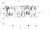
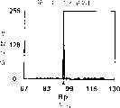
如在“相关技术描述”中所述,在光电传感器系统应用指纹读取装置时,根据作为被摄物体的手指皮肤表层的状态可能不设置适当的图像读取灵敏度。手指的皮肤表层经常角质化,被指纹的脊状部分反射的光量增加,从而观察到的亮度局部高。与读取没有角质化皮肤的手指指纹的情况相比,相对大的动态范围能够在短的电荷积累周期内以相对低的图像读取灵敏度获得。根据所读取的指纹图像数据,相应于最大动态范围的图像读取灵敏度(标准图像读取灵敏度)被提取作为最佳图像读取灵敏度。在这种情况下,比原先的最佳图像读取灵敏度低的图像读取灵敏度,即比原先的最佳电荷积累周期短的电荷积累周期被提取和设置。如果基于该图像读取灵敏度执行正常指纹读取操作,那么目标图像就被读取为较暗的图像并且图像中的脊状部分趋向于不连续,如图7A所示,因为电荷积累周期设置得比原先的最佳电荷积累周期短。对于目标图像,任意行(例如第81行)的亮度数据的分布特性被检查,并发现其呈现具有大动态范围的亮度数据分布,如图7B所示。这是因为在角质化皮肤表层脊状部分的影响下存在具有非常高的亮度数据最大值的像素(列)。该分布并不精确地对应指纹的原始图案。因此,指纹不能被精确读取,降低了外部功能部分中指纹核对处理的精确性。As described in "Description of Related Art", when a fingerprint reading device is applied to a photosensor system, appropriate image reading sensitivity may not be set depending on the state of the skin surface layer of a finger as an object. The skin surface layer of the finger is often keratinized, and the amount of light reflected by the ridges of the fingerprint increases, so that the brightness observed is locally high. Compared with the case of reading finger prints without keratinized skin, a relatively large dynamic range can be obtained with a relatively low image read sensitivity within a short charge accumulation period. Based on the read fingerprint image data, the image reading sensitivity (standard image reading sensitivity) corresponding to the maximum dynamic range is extracted as the optimum image reading sensitivity. In this case, an image reading sensitivity lower than the original optimum image reading sensitivity, that is, a charge accumulation period shorter than the original optimum charge accumulation period is extracted and set. If a normal fingerprint reading operation is performed based on this image reading sensitivity, the target image is read as a darker image and the ridges in the image tend to be discontinuous as shown in FIG. 7A because the charge accumulation period is set to Shorter than previous optimum charge accumulation period. With respect to the target image, distribution characteristics of luminance data of an arbitrary line (for example, the 81st line) are checked, and found to exhibit a distribution of luminance data with a large dynamic range, as shown in FIG. 7B . This is because there are pixels (columns) having a very high brightness data maximum value under the influence of the ridge portion of the cornified skin surface layer. This distribution does not exactly correspond to the original pattern of the fingerprint. Therefore, the fingerprint cannot be accurately read, reducing the accuracy of the fingerprint collation process in the external function section.
相反地,按照第一实施例的光电传感器系统的灵敏度调整装置和方法基于图像读取灵敏度(标准图像读取灵敏度)的预定周期增加率(例如约30%)执行校正处理,其中的图像读取灵敏度提供最大动态范围并且通过对皮肤表层角质化的手指的指纹图像数据进行灵敏度调整读取操作和图像读取灵敏度调整操作而获得。与图7A中所示的图像相比,更高的图像读取灵敏度即更长的电荷积累周期被设置。因此,更接近原先的最佳图像读取灵敏度的图像读取灵敏度被设置。In contrast, the sensitivity adjustment device and method of the photosensor system according to the first embodiment executes correction processing based on a predetermined cycle increase rate (for example, about 30%) of the image reading sensitivity (standard image reading sensitivity) in which the image reading The sensitivity provides the maximum dynamic range and is obtained by performing a sensitivity adjustment reading operation and an image reading sensitivity adjustment operation on fingerprint image data of a finger whose skin surface layer is keratinized. Compared with the image shown in FIG. 7A , higher image reading sensitivity, ie, a longer charge accumulation period is set. Therefore, an image reading sensitivity closer to the original optimum image reading sensitivity is set.
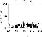
通过根据校正过的图像读取灵敏度执行正常指纹读取操作,目标图像被读取为具有适当亮度的图像,并且能够获得具有几乎不间断的脊状部分的高质量图像,如图8A所示。对目标图像检查任意行(例如第81行)的亮度数据的分布特性,并发现其呈现具有相对大的动态范围的亮度数据分布,如图8B所示。另外,在既不是最大值也不是最小值处观察到在角质化皮肤表层影响下的极端(extreme)亮度数据。与指纹的原始图案精确地对应的稳定图像被获得。结果,指纹核对处理能够在外部功能部分200中被高精确度地执行。By performing a normal fingerprint reading operation according to the corrected image reading sensitivity, the target image is read as an image with appropriate brightness, and a high-quality image with almost uninterrupted ridge portions can be obtained, as shown in FIG. 8A . The distribution characteristics of the luminance data of an arbitrary line (for example, the 81st line) are checked for the target image, and found to exhibit a distribution of luminance data having a relatively large dynamic range, as shown in FIG. 8B . In addition, extreme brightness data under the influence of the keratinized skin surface were observed at neither the maximum nor the minimum. A stable image is obtained that corresponds exactly to the original pattern of the fingerprint. As a result, fingerprint collation processing can be executed with high accuracy in the
按照第一实施例的灵敏度调整装置和方法,在正常图像读取操作之前使用实际被摄物体执行灵敏度调整读取操作,同时图像读取灵敏度逐行地改变。最佳图像读取状态中的行基于每行的亮度数据动态范围被容易地确定,并且为所确定的行设置的图像读取灵敏度(标准图像读取灵敏度)被提取。然后,基于预定周期增加率的校正处理被执行来设置最佳图像读取灵敏度。甚至在被摄物体的亮度随着环境照度的变化而变化,或由于被摄物体的个体差异和外部环境(温度、湿度等)而存在波动因素或趋势时,灵敏度调整处理用简单的方法唯一地被执行以极大地抑制外部光的环境照度或皮肤表层角质化的影响。最佳图像读取灵敏度能够被设置,并且目标图像能够由正常图像读取操作精确地读取。According to the sensitivity adjustment apparatus and method of the first embodiment, the sensitivity adjustment reading operation is performed using an actual subject prior to the normal image reading operation while the image reading sensitivity is changed line by line. The row in the optimum image reading state is easily determined based on the dynamic range of luminance data for each row, and the image reading sensitivity (standard image reading sensitivity) set for the determined row is extracted. Then, correction processing based on a predetermined period increase rate is performed to set the optimum image reading sensitivity. Even when the brightness of the subject changes with changes in ambient illuminance, or there are fluctuation factors or trends due to individual differences in the subject and the external environment (temperature, humidity, etc.), the sensitivity adjustment process uniquely Performed to greatly suppress the influence of ambient illuminance of external light or keratinization of the skin surface. The optimum image reading sensitivity can be set, and the target image can be accurately read by normal image reading operation.
在该实施例中,灵敏度调整处理仅对作为代表性行的图5A-5E所示的第176、152、128、104和80行进行了描述。灵敏度调整处理可以对构成光电传感器阵列100的全部256行或对特定行(例如图5A-5E中的每24行)执行。In this embodiment, the sensitivity adjustment processing is described only for the 176th, 152, 128, 104, and 80th lines shown in FIGS. 5A-5E as representative lines. The sensitivity adjustment process may be performed on all 256 rows constituting the
当对所有行执行灵敏度调整处理时,更佳的图像读取灵敏度能够从为各行所设置的图像读取中提取。如果灵敏度调整处理仅对特定行执行,那么须经一系列处理操作的数据数目能够大大减少从而减低控制器150上的处理负荷并且缩短处理时间。灵敏度调整读取操作能够迅速转换为目标图像的正常读取操作。When the sensitivity adjustment processing is performed for all rows, better image reading sensitivity can be extracted from image reading set for each row. If the sensitivity adjustment processing is performed only for a specific row, the number of data subject to a series of processing operations can be greatly reduced to reduce the processing load on the
在该实施例中,目标图像(指纹图像)在灵敏度调整读取操作中由光电传感器阵列100的整个传感面读取。本发明不限于此,并且灵敏度调整处理可以通过读取仅在由预定有限区域所形成的检测区域中的目标图像来进行,如第三实施例中的图15A和15B(以后说明)。在这种情况中,读取时间能够被缩短,并且须经处理操作的数据数目能够被进一步减少以缩短处理时间。灵敏度调整读取操作能够更快地转换为目标图像的正常读取操作。In this embodiment, the target image (fingerprint image) is read by the entire sensing surface of the
在上述实施例中,在由灵敏度调整读取操作所获得的各行亮度数据中,为具有最大动态范围的行所设置的图像读取灵敏度根据在周期增加寄存器157中事先设置的预定周期增加率唯一地经受周期增加校正处理。但是本发明不限于此。In the above-described embodiment, among the luminance data of each line obtained by the sensitivity adjustment reading operation, the image reading sensitivity set for the line having the largest dynamic range is unique according to the predetermined period increase rate set in advance in the
例如,在周期增加寄存器157中设置的周期增加率可以通过光电传感器系统(或控制器150)之外的输入操作任意地设置。这通过操作外部功能部分200的输入/输出接口装置(未示出),输入一任意周期增加率作为数字数据,然后重新写入周期增加寄存器157来实现。For example, the period increase rate set in the
作为任意地重新写入的周期增加值的配置被适当应用的示例,光电传感器系统被应用于指纹读取装置。在该配置中,当被摄物体的类型被限制或指定为一定程度,并且作为被摄物体的个体的年龄或性别或者外部环境例如温度或湿度被事先掌握时,每次适当的周期增加率根据这样的波动因素或趋势或者通过事先输入数值来设置。更佳的图像读取灵敏度能够在抑制个体差异或外部环境影响的同时被设置。目标图像能够被精确读取。As an example in which the configuration of arbitrarily rewritten cycle-increased values is appropriately applied, a photosensor system is applied to a fingerprint reading device. In this configuration, when the type of the subject is limited or designated to a certain degree, and the age or sex of the individual as the subject or the external environment such as temperature or humidity is grasped in advance, an appropriate cycle increase rate per time is determined according to Such fluctuation factors or trends are either set by inputting numerical values in advance. Better image reading sensitivity can be set while suppressing individual differences or external environmental influences. The target image can be read accurately.
基于周期增加率的校正在第一实施例中始终执行,但是本发明不限于此。例如,在其中光电传感器系统应用于指纹读取装置的配置中,最佳图像读取灵敏度被提取并设置而无需应用基于周期增加率的校正处理。然后,进行正常目标图像读取操作来执行指纹核对处理。如果结果被拒绝,则基于周期增加率的校正处理被应用来校正图像读取灵敏度。以校正的图像读取灵敏度,正常目标图像读取操作被再次执行以进行指纹核对处理。在这种情况中,正常目标图像读取操作能够被迅速完成而没有任何校正处理的处理时间,除非被摄物体(指纹)的皮肤状态为角质化。Correction based on the cycle increase rate is always performed in the first embodiment, but the present invention is not limited thereto. For example, in a configuration in which a photosensor system is applied to a fingerprint reading device, optimum image reading sensitivity is extracted and set without applying correction processing based on a cycle increase rate. Then, a normal target image reading operation is performed to perform fingerprint collation processing. If the result is rejected, a correction process based on the rate of cycle increase is applied to correct the image reading sensitivity. With the corrected image reading sensitivity, the normal target image reading operation is performed again for fingerprint collation processing. In this case, the normal target image reading operation can be quickly completed without any processing time for correction processing unless the skin state of the subject (fingerprint) is keratinized.
<第二实施例><Second Embodiment>
按照本发明的光电传感器系统的第二实施例将参考几个图描述。A second embodiment of the photosensor system according to the invention will be described with reference to several figures.
图9是示出按照第二实施例应用于光电传感器系统的控制器的配置的框图。与图2所示的第一实施例相同的参考数字表示相同的部分,并且其说明将被简化或省略。Fig. 9 is a block diagram showing the configuration of a controller applied to the photosensor system according to the second embodiment. The same reference numerals as those of the first embodiment shown in FIG. 2 denote the same parts, and descriptions thereof will be simplified or omitted.
类似于按照第一实施例的灵敏度调整方法,第二实施例提取由灵敏度调整读取操作所获得的亮度数据分布中具有最大动态范围的行的图像读取灵敏度。然后,确定是否对所提取的图像读取灵敏度执行周期增加校正处理,并且设置更佳的图像读取灵敏度。Similar to the sensitivity adjustment method according to the first embodiment, the second embodiment extracts the image reading sensitivity of the row having the largest dynamic range in the luminance data distribution obtained by the sensitivity adjustment reading operation. Then, it is determined whether to perform cycle increase correction processing on the extracted image reading sensitivity, and a better image reading sensitivity is set.
如图9所示,第二实施例中的控制器150包括装置控制器151,数据控制器152,主控制器153,数据比较器154,加法器155,数据选择器156,周期增加寄存器157和灵敏度设置寄存器159,所有这些部件都具有与图2所示的第一实施例相同的配置。另外,控制器150包括平均比较值寄存器158,它保持有用作参考值的平均比较值,它用于确定是否对由数据比较器154、加法器155和数据选择器156所提取的并与最大动态范围对应的图像读取灵敏度执行主控制器153的周期增加校正。在第二实施例中,保持在平均比较值寄存器158中的平均比较值基于通过目标图像的灵敏度调整读取操作所获得的亮度数据分布中的最大动态范围被唯一地设置。As shown in Figure 9, the
由控制器进行的处理操作将参考几个图说明。The processing operations performed by the controller will be explained with reference to several figures.
图10是示出按照第二实施例由应用于光电传感器系统的控制器所执行的灵敏度调整/设置处理的示例的流程图。与图3所示的第一实施例相同的处理步骤的描述将被简化或省略。10 is a flowchart showing an example of sensitivity adjustment/setting processing performed by a controller applied to a photosensor system according to the second embodiment. Descriptions of the same processing steps as those of the first embodiment shown in FIG. 3 will be simplified or omitted.
(步骤S21-S26)(steps S21-S26)
如图10所示,类似于第一实施例中的步骤S11-S16,在被摄物体的正常读取操作之前的定时,为各行设置不同的图像读取灵敏度。灵敏度调整目标图像读取操作被执行来获得与目标图像的明/暗图案相应的每个图像读取灵敏度的像素数据(亮度数据)。表示最大和最小值的亮度数据从每个图像读取灵敏度(例如每行)的亮度数据中提取。最大和最小值之间的差被计算来获得每个图像读取灵敏度的动态范围,并且动态范围被存储在RAM160中。最大值从存储在RAM160中的各图像读取灵敏度的动态范围中提取,并且相应的图像读取灵敏度(电荷积累周期)被提取。As shown in FIG. 10 , similarly to steps S11 - S16 in the first embodiment, different image reading sensitivities are set for the respective lines at the timing before the normal reading operation of the subject. The sensitivity adjustment target image reading operation is performed to obtain pixel data (brightness data) of each image reading sensitivity corresponding to the light/dark pattern of the target image. The luminance data representing the maximum and minimum values are extracted from the luminance data of each image read sensitivity (for example, each row). The difference between the maximum and minimum values is calculated to obtain the dynamic range of each image reading sensitivity, and the dynamic range is stored in the
(步骤S27和S28)(steps S27 and S28)
主控制器153控制数据控制器152,从而计算与动态范围取最大值时的图像读取灵敏度,即步骤S26中所提取的图像读取灵敏度相应的像素数据(亮度数据)的平均值,并计算动态范围的中间值(平均比较值)。The
所计算的亮度数据的平均值经数据选择器156临时存储在RAM160中。动态范围的中间值经数据选择器156和数据控制器152保持在平均比较值寄存器158中。The calculated average value of luminance data is temporarily stored in
(步骤S29)(step S29)
主控制器153控制数据控制器152,从而执行将在步骤S27中计算并存储在RAM160中的亮度数据的平均值与在步骤S28中计算并保持在平均比较值寄存器158中的最大动态范围的中间值进行比较的处理。The
如果角质化的手指作为被摄物体读取,被角质化手指的脊状部分所反射的光量可能增加,并且观察到的亮度可能局部高,如图7B所示。在这种情况中,亮度数据呈现局部高。为此,在角质化的影响下被确定为具有最大动态范围的行的亮度数据可能仅是一组除了局部高的数据之外的小的亮度数据。由此,当亮度数据的平均值相对小时,甚至具有最大动态范围的行在角质化的影响下被确定为一组小的亮度数据。相应于该行的图像读取灵敏度能够被确定为低于原始最佳图像读取灵敏度。If a horny finger is read as a subject, the amount of light reflected by the ridged portion of the horny finger may increase, and the observed brightness may be locally high, as shown in FIG. 7B . In this case, the luminance data appears locally high. For this reason, the luminance data of a row determined to have the largest dynamic range under the influence of keratinization may be only a small set of luminance data except locally high data. Thus, when the average value of the luminance data is relatively small, even the row with the largest dynamic range is determined as a small set of luminance data under the influence of keratinization. The image read sensitivity corresponding to this row can be determined to be lower than the original optimum image read sensitivity.
呈现最大动态范围的行中的亮度数据平均值是小还是大通过比较亮度数据的平均值与动态范围的中间值,或比较该行的亮度数据之和与动态范围中间值与列号的乘积来确定。Whether the mean value of the luminance data in the row exhibiting the greatest dynamic range is small or large is determined by comparing the mean value of the luminance data with the midpoint of the dynamic range, or comparing the sum of the luminance data for that row with the product of the midpoint of the dynamic range multiplied by the column number Sure.
如果亮度数据的平均值(或亮度数据之和)小于动态范围的中间值(或中间值和列号的乘积),那么该行能够被确定为具有角质化影响下的不适当的亮度数据分布。如果是平均值较大,那么该行能够被确定为不受任何角质化影响的适当亮度数据分布。以下的处理操作基于该确定的结果来执行。If the average value of the luminance data (or the sum of the luminance data) is less than the median value of the dynamic range (or the product of the median value and the column number), then the row can be determined to have an inappropriate distribution of luminance data under the influence of keratinization. If the average value is larger, then the row can be determined as an appropriate distribution of luminance data not affected by any keratinization. The following processing operations are performed based on the result of this determination.
(步骤S30和S31)(steps S30 and S31)
如果在图像读取灵敏度具有最大动态范围时的亮度数据的平均值在步骤S29中被确定为小于动态范围的中间值,那么主控制器153确定在该图像读取灵敏度时的亮度数据分布不适当。主控制器153控制数据控制器152,从而根据事先在周期增加寄存器157中设置的或经外部功能部分200等任意输入和设置的预定周期增加率,对具有该动态范围的图像读取灵敏度执行周期增加校正处理。If the average value of the luminance data when the image reading sensitivity has the maximum dynamic range is determined to be smaller than the middle value of the dynamic range in step S29, the
通过以周期增加校正处理中的周期增加率增加图像读取灵敏度而校正的值被设置为图像读取灵敏度,其中图像读取灵敏度在步骤S26中被提取并具有最大动态范围。即,电荷积累周期被延长了与周期增加率相对应的时间。A value corrected by increasing the image read sensitivity extracted in step S26 and having the maximum dynamic range at the cycle increase rate in the cycle increase correction process is set as the image read sensitivity. That is, the charge accumulation period is extended by a time corresponding to the period increase rate.
然后,数据控制器152重写灵敏度设置寄存器159以设置所校正的图像读取灵敏度(电荷积累周期)。Then, the
(步骤S32)(step S32)
如果在图像读取灵敏度具有最大动态范围时的亮度数据的平均值在步骤S29中被确定为大于动态范围的中间值,那么主控制器153确定在该图像读取灵敏度时的亮度数据分布适当。数据控制器152重写灵敏度设置寄存器159而不执行周期增加校正,并设置步骤S26中所提取的图像读取灵敏度(电荷积累周期)。If the average value of the luminance data when the image reading sensitivity has the maximum dynamic range is determined to be larger than the middle value of the dynamic range in step S29, the
在根据通过在正常图像读取操作以前所执行的灵敏度调整读取操作获得的每个图像读取灵敏度的亮度数据动态范围,来设置最佳图像读取灵敏度(电荷积累周期)的图像读取灵敏度调整操作中,光电传感器系统的灵敏度调整装置和方法能够根据图像读取灵敏度具有最大动态范围时的亮度数据是否是在手指角质化等(波动因素或趋势,例如被摄物体的个体差异或外部环境)的影响下的不适当,来确定是否对所提取的图像读取灵敏度执行周期增加校正处理。仅对不适当图像读取灵敏度能够通过执行校正处理来设置适当的图像读取灵敏度。The image reading sensitivity of the optimum image reading sensitivity (charge accumulation period) is set in accordance with the dynamic range of luminance data of each image reading sensitivity obtained by the sensitivity adjustment reading operation performed before the normal image reading operation In the adjustment operation, the sensitivity adjustment device and method of the photoelectric sensor system can be based on whether the brightness data when the image reading sensitivity has the maximum dynamic range is in the horny fingers, etc. (fluctuation factors or trends, such as individual differences in objects or external environments ) to determine whether to perform cycle increase correction processing on the extracted image reading sensitivity. Appropriate image read sensitivity can be set by performing correction processing only for inappropriate image read sensitivity.
在第二实施例中,当对由灵敏度调整读取操作所获得的各图像读取灵敏度的亮度数据中的具有最大动态范围的图像读取灵敏度确定是否基于预定周期增加率执行周期增加校正时,动态范围的中间值被唯一地设置来与图像读取灵敏度的亮度数据平均值进行比较。但是,本发明不限于此。In the second embodiment, when determining whether to perform cycle increase correction based on a predetermined cycle increase rate for the image read sensitivity having the largest dynamic range among the luminance data of the respective image read sensitivities obtained by the sensitivity adjustment read operation, The middle value of the dynamic range is uniquely set to compare with the average value of the luminance data of the image reading sensitivity. However, the present invention is not limited thereto.
例如,动态范围的中间值可以用作缺省值(参考值),并且在平均比较值寄存器158中所设置的平均比较值可以被光电传感器(或控制器150)之外的输入操作任意地改变和设置。For example, the middle value of the dynamic range can be used as a default value (reference value), and the average comparison value set in the average comparison value register 158 can be arbitrarily changed by an input operation other than the photosensor (or controller 150) and settings.
类似于第一实施例中所述的周期增加寄存器157,通过操作外部功能部分200的输入/输出接口装置(未示出),输入一任意的平均比较值作为数字数据来重写平均比较值寄存器158。作为任意地重写平均比较值的配置被适当应用的示例,光电传感器系统被应用于指纹读取装置。在该配置中,当通过用指纹图案的脊状部分(例如在图7A和8A中所观察到的白色的部分)作为参考在外部功能部分200中执行指纹核对处理时,平均比较值被设置为相对大的值以便于上述周期增加校正处理的执行。Similar to the
作为另一个示例,在允许通过传感器等事先掌握外部环境例如温度的配置中,如果湿度低,那么平均值被设置为相对大的数值,因为皮肤表层易于角质化。这便于上述周期增加校正处理的执行。As another example, in a configuration that allows the external environment such as temperature to be grasped in advance by a sensor or the like, if the humidity is low, the average value is set to a relatively large value because the surface layer of the skin tends to be keratinized. This facilitates execution of the cycle increase correction process described above.
作为又一个示例,在使得能够通过ID卡等掌握用作被摄物体的个体的特征的配置中,对呈现指纹核对处理的低鉴定概率的个体,平均比较值被设置为相对大的数值。这也便于上述周期增加校正处理的执行。As yet another example, in a configuration that enables the characteristics of individuals serving as subjects to be grasped through ID cards or the like, the average comparison value is set to a relatively large value for individuals exhibiting low identification probability of fingerprint collation processing. This also facilitates execution of the cycle increase correction process described above.
因此,在抑制个体差异或外部环境的影响的同时,更佳的图像读取灵敏度能够被设置来精确地读取目标图像。Therefore, better image reading sensitivity can be set to accurately read the target image while suppressing individual differences or the influence of the external environment.
<第三实施例><Third embodiment>
按照本发明的光电传感器系统的第三实施例将参考几个图来说明。A third embodiment of the photosensor system according to the invention will be described with reference to several figures.
图11是示出按照第三实施例的光电传感器系统的整体配置的框图。图26A所示的双栅极光电传感器被用来作为光电传感器,并且需要时将参考图27所示的光电传感器系统的配置。和在图1所示的光电传感器系统中相同的参考数字表示相同的部分,并且其描述将被简化或省略。Fig. 11 is a block diagram showing the overall configuration of a photosensor system according to a third embodiment. A double-gate photosensor shown in FIG. 26A is used as a photosensor, and the configuration of the photosensor system shown in FIG. 27 will be referred to as necessary. The same reference numerals denote the same parts as in the photosensor system shown in FIG. 1, and descriptions thereof will be simplified or omitted.
如图11所示,类似于图1所示的光电传感器系统,按照第三实施例的光电传感器系统大体上包括光电传感器阵列100,顶栅极驱动器110,底栅极驱动器120,由列开关131、预充电开关132和放大器133组成的输出电路部分130,A/D转换器140,控制器150,和RAM160,RAM160用于临时存储所获得的图像数据(像素数据组)并及与(下面要说明的)灵敏度设置处理有关的处理数据等。光电传感器系统进一步包括保持有控制器150的控制程序和各种控制数据的ROM170。As shown in FIG. 11, similar to the photosensor system shown in FIG. 1, the photosensor system according to the third embodiment generally includes a
类似于第一和第二实施例,控制器150具有以下功能:对被摄物体执行灵敏度调整读取操作,并根据所读取的图像数据来控制能够精确地读取目标图像的图像读取灵敏度的提取和设置。此外,如下所述,控制器150具有以下功能:从在灵敏度调整读取操作中为灵敏度调整所读取的目标图像的图像数据(像素数据组)中去除特定像素数据,以便防止或抑制由杂质例如沉积在光电传感器阵列的传感表面上的灰尘所造成的异常像素数据的影响或光电传感器阵列上存在的元件缺陷的影响。Similar to the first and second embodiments, the
应用于按照第三实施例的光电传感器系统的控制器的详细配置和操作将参考几个图来更详细地说明。The detailed configuration and operation of the controller applied to the photoelectric sensor system according to the third embodiment will be explained in more detail with reference to several drawings.
图12是示出应用于按照该实施例的光电传感器系统的控制器的配置的框图。FIG. 12 is a block diagram showing the configuration of a controller applied to the photosensor system according to this embodiment.
如图12所示,类似于图2所示的第一实施例,第三实施例中的控制器150包括装置控制器151,用于控制顶栅极驱动器110、底栅极驱动器120和预充电开关132的操作;数据控制器152,用于执行向RAM160和ROM170的数据的写入/读出并管理各种数据;以及主控制器153,根据预定控制程序来监督控制器151和152、与外部功能部分200接口连接并交换控制信号的。控制器150进一步包括:数据比较器154,通过比较包含在经A/D转换器140从光电传感器阵列100作为数字信号输入的图像数据中的初始像素数据(为了说明方便在下文中也称为“原始像素数据”)的大小,或特定像素数据通过特定像素数据去除操作(在以后说明)进行去除处理以后所获得的像素数据(为了说明方便在下文中也称为“处理过的像素数据”)的大小,来提取最大和最小值,并用于提取由加法器155所计算的最大动态范围;加法器155,用于从由数据比较器154所提取的处理过的像素数据的最大和最小值之间的差来计算动态范围;数据选择器156,用于接收图像数据和处理经A/D转换器140、数据比较器154和加法器155所处理的图像数据和处理数据,并在需要时这些数据向RAM160的写入/读出、这些数据向数据比较器154和加法器155的重新输入和这些数据经数据控制器152向外部功能部分200的输出之间切换;以及灵敏度设置寄存器159,用于设置要从装置控制器151输出至顶栅极驱动器和底栅极驱动器110和120的控制信号φtg和φbg的定时,以便根据来自于数据控制器152的控制信号优化光电传感器阵列100的图像读取灵敏度。As shown in FIG. 12, similar to the first embodiment shown in FIG. 2, the
主控制器153具有以下的去除特定像素数据的功能。更详细地,主控制器153经数据选择器156在RAM160的预定存储区域中仅写入除特定像素数据以外的像素数据组,该特定像素数据是基于预定的条件并由数据比较器154所提取的,例如具有原始像素数据的最大或最小值的像素数据。结果,主控制器153能够产生去除了具有最大或最小值的像素数据的像素数据(处理像素数据)群。主控制器153的特定像素数据去除操作将在以后详细说明。The
由灵敏度设置寄存器159在光电传感器阵列100、顶栅极驱动器110和底栅极驱动器120中设置最佳图像读取灵敏度的方法将详细说明。该方法也包括与第一和第二实施例相同的步骤。即,通过比较由从光电传感器阵列输入的图像数据(原始图像数据)而产生的对于每个图像读取灵敏度的处理像素数据中包含的亮度数据大小,对每个图像读取灵敏度计算动态范围。产生最大动态范围的图像读取灵敏度被设置作为最佳值。A method of setting optimum image reading sensitivity in the
由具有上述配置的控制器进行的处理操作将参考几个图说明。Processing operations performed by the controller having the above configuration will be explained with reference to several figures.
图13是示出由应用于按照第三实施例的光电传感器系统的控制器所执行的灵敏度调整/设置处理的示例的流程图。与图3所示第一实施例中的相同的处理步骤将被简化或省略。13 is a flowchart showing an example of sensitivity adjustment/setting processing performed by a controller applied to the photosensor system according to the third embodiment. The same processing steps as in the first embodiment shown in FIG. 3 will be simplified or omitted.
以下一系列的处理步骤通过将事先存贮在ROM170中的控制程序载入RAM160并由控制器150执行该程序来实现。The following series of processing steps are realized by loading the control program previously stored in the
(步骤S41)(step S41)
如图13所示,主控制器153在目标图像的正常读取操作以前的定时开始灵敏度调整读取操作。主控制器153经数据控制器152在灵敏度设置寄存器159中为灵敏度调整读取操作设置图像读取灵敏度。主控制器153读取放置于传感面上的灵敏度调整目标图像,该传感面限定在光电传感器阵列100的一面上。在逐行地改变光电传感器阵列100的电荷积累周期从而增加对更大行号的图像读取灵敏度的同时,执行该灵敏度调整读取操作,如图4所示。因此,以不同图像读取灵敏度读取的图像数据通过一个读取操作来获得。As shown in FIG. 13 , the
(步骤S42)(step S42)
由灵敏度调整读取操作所读取的图像数据经A/D转换器140转换为数字信号,并且该数字信号经数据选择器156被临时存储在RAM160中。此后,数据控制器152经数据选择器156将该数字数据作为每个图像读取灵敏度的原始像素数据(亮度数据)输入给数据比较器154。The image data read by the sensitivity adjustment reading operation is converted into a digital signal by the A/
(步骤S43)(step S43)
对于每个图像读取灵敏度,数据比较器154比较所输入的原始像素数据的亮度数据的大小。数据比较器154提取满足预定条件的特定像素数据,即具有最大亮度数据值的像素数据或亮度数据值降序排列的多个像素数据。For each image reading sensitivity, the
(步骤S44)(step S44)
在步骤S43中所提取的具有最大值的像素数据或包含最大值的预定数目的像素数据从对于每个图像读取灵敏度的原始像素数据组中去除。剩余的图像数据群存储在RAM160的预定存储区域中,产生通过从原始像素数据组中去除特定像素数据而获得的像素数据组(处理过的像素数据)。特定像素数据去除操作的详细示例将在以后说明。The pixel data having the maximum value or the predetermined number of pixel data containing the maximum value extracted in step S43 is removed from the raw pixel data group for each image read sensitivity. The remaining image data group is stored in a predetermined storage area of the
(步骤S45和S46)(steps S45 and S46)
数据控制器152提取对于每个图像读取灵敏度的处理过的像素数据,并经数据选择器156将该数据载入数据比较器154中。数据比较器154比较对于每个图像读取灵敏度的处理像素数据的大小,并提取具有最大和最小亮度数据值的像素数据。The
(步骤S47)(step S47)
由数据控制器152所控制的加法器155计算对于每个图像读取灵敏度所提取的像素数据的最大和最小亮度数据值之间的差,从而获得对于每个图像读取灵敏度的动态范围。结果经数据选择器156临时存储在RAM160中。The
对各图像读取灵敏度执行该动态范围计算处理。This dynamic range calculation processing is executed for each image reading sensitivity.
(步骤S48)(step S48)
存储在RAM160中的对于各图像读取灵敏度的动态范围经数据选择器156读出,并载入数据比较器154中。数据比较器154比较对于各图像读取灵敏度的动态范围,并提取最大动态范围。The dynamic range for each image reading sensitivity stored in
(步骤S49)(step S49)
灵敏度设置寄存器159经数据控制器152被重写,以将与所提取的最大动态范围相对应的图像读取灵敏度设置为最佳图像读取灵敏度。The
应用于控制器的上述处理操作的灵敏度调整读取操作(步骤S41)将参考几个图详细说明。The sensitivity adjustment reading operation (step S41) applied to the above processing operation of the controller will be described in detail with reference to several figures.
图14A和14B是示出按照第三实施例的在灵敏度调整读取操作中读取操作的目标区域和示例的概念视图。图15A和15B是示出按照第三实施例的在灵敏度调整读取操作中读取操作的另一个目标区域和另一个示例的概念视图。14A and 14B are conceptual views showing target areas and examples of a reading operation in a sensitivity adjustment reading operation according to the third embodiment. 15A and 15B are conceptual views showing another target area of a reading operation and another example in the sensitivity adjustment reading operation according to the third embodiment.
应用于第三实施例的灵敏度调整读取操作被如下执行。根据从装置控制器151输出的及在顶栅极驱动器110、底栅极驱动器120和预充电开关132中设置的控制信号和图像读取灵敏度,在从光电传感器阵列100的整个传感面形成的有效读取区域30内,如图14A和14B所示,或者在由限制于并事先设置在有效读取区域30内的预定区域形成的检测区域40内,如图15A和15B所示,读取放置在传感面上的灵敏度调整图像。The sensitivity adjustment read operation applied to the third embodiment is performed as follows. According to the control signal and image reading sensitivity output from the
在构成光电传感器阵列100的双栅极光电传感器10中所设置的图像读取灵敏度可以被设置得相互不同,例如,逐行地、每预定行数或每读取区域如,每有效读取区域30或每检测区域40。The image reading sensitivities set in the
对于灵敏度调整读取操作中的光电传感器10的详细驱动方法,由256×196像素组成的光电传感器阵列100中的所有行可以被顺序读取,如图14A所示。可选地,每多个行(在该情况下,每10行)例如第10、20、…、180和190行可以被顺序地读取,如图14B所示。As for the detailed driving method of the photosensor 10 in the sensitivity adjustment read operation, all rows in the
例如,由第64至第191行的行范围和第67至第130列的列范围形成的检测区域40中的所有行可以被顺序地读取,如图15A所示。可选地,每多个行(在该情况中,每10行)例如第70、80、…、180和190行可以被顺序地读取,如图15B所示。For example, all the rows in the
在第三实施例中,要在被摄物体的正常图像读取操作中读取的区域可以被直接设置为须经灵敏度调整读取操作的区域(有效读取区域30或检测区域40)。对于检测区域40,包括在该区域(行和列范围)内的像素数目可以被设置,从而具有在应用于该实施例的特定像素数据去除操作和最佳图像读取灵敏度设置操作中令人满意地执行处理操作所需的至少最小数目的像素数据。按照第三实施例须经灵敏度调整读取操作的区域不限于检测区域40的设置区域(从第64行至第191行和第67列至第130列的128行)。可以设置由更窄(像素的更小数目)的行和列范围所定义的区域。能够被设置为检测区域的最小区域的设置将在以后验证。In the third embodiment, the area to be read in the normal image reading operation of the subject can be directly set as the area subject to the sensitivity adjustment reading operation (
应用于控制器的处理操作的特定像素数据去除操作(步骤S43和S44)将被举例说明。A specific pixel data removal operation (steps S43 and S44 ) applied to the processing operation of the controller will be exemplified.
在应用于该实施例的特定像素数据去除操作中,以亮度数据值的降序提取一个或多个像素数据的操作能够采用以下方法。In the specific pixel data removal operation applied to this embodiment, the operation of extracting one or more pieces of pixel data in descending order of luminance data values can adopt the following method.
更详细地,在上述步骤S43中,对每个图像读取灵敏度比较载入数据比较器154的原始像素数据的亮度数据值。原始像素数据以亮度数据值的降序排序被分类拣选并经数据选择器156存储在RAM160中。In more detail, in the above-mentioned step S43 , the luminance data values of the raw pixel data loaded into the
在步骤S44-S46中,当存储在RAM160中以计算动态范围的像素数据要再次装入数据比较器154时,从第一至第n(n是任意自然数)个像素数据的预定数目,以亮度数据值的降序从对于每图像读取灵敏度以上述方式分类拣选的原始像素数据组中被唯一地指定和去除。剩余像素数据组(相应于处理像素数据)被装入数据比较器154中。在装入的像素数据组中,具有最大亮度数据值的像素数据,即次于被指定/去除的像素数据的第二大像素数据,和具有最小亮度数据值的像素数据经数据选择器156被提取和读出。加法器155计算像素数据的最大和最小值之间的差,即动态范围。In steps S44-S46, when the pixel data stored in the
通过比较像素数据并按它们的大小对它们分类拣选的该简单处理,具有最大亮度数据值(最高亮度)的像素数据或以亮度数据值的降序排列的预定数目的像素数据被从原始像素数据组中唯一地去除。此外,具有最大和最小值的像素数据被从处理过的像素数据组中提取。By this simple process of comparing pixel data and sorting them by their sizes, pixel data having the largest luminance data value (highest luminance) or a predetermined number of pixel data arranged in descending order of luminance data values are extracted from the original pixel data group. uniquely removed from . In addition, pixel data having maximum and minimum values are extracted from the processed pixel data set.
对各行设置不同的图像读取灵敏度的情况将被说明。A case where different image reading sensitivities are set for each row will be described.
在步骤S103中,对于每行即每个图像读取灵敏度,载入数据比较器154中的原始像素数据组中的、在光电传感器阵列上彼此相邻的像素的像素数据的大小被比较,从而例如以大小下降的顺序从目标行的第一像素中顺序地提取像素数据。In step S103, for each row, that is, for each image reading sensitivity, the magnitudes of pixel data of pixels adjacent to each other on the photosensor array in the raw pixel data set loaded in the
更详细地,如图16的(a)和(b)所示,在一行的像素数据组(m像素数据)中比较第一像素的像素数据(第一像素数据)和第二像素的像素数据(第二像素数据)来提取具有较大亮度数据值(较高亮度)的像素数据。所提取的像素数据和第三像素的像素数据(第三像素数据)比较来提取具有更大亮度数据值的像素数据。该处理被执行,一直到目标行的第m个像素数据。In more detail, as shown in (a) and (b) of FIG. (second pixel data) to extract pixel data with a larger luminance data value (higher luminance). The extracted pixel data is compared with pixel data of a third pixel (third pixel data) to extract pixel data having a larger luminance data value. This processing is performed up to the mth pixel data of the target row.
通过比较相邻像素的像素数据,总是仅仅具有较大的亮度数据值的像素数据被提取并须经下一个比较处理。该比较/提取处理对一行的像素数据组是重复执行的,仅提取具有最大亮度数据值(最高亮度)的像素数据。By comparing the pixel data of adjacent pixels, always only the pixel data with a larger luminance data value is extracted and subjected to the next comparison process. This comparison/extraction process is repeatedly performed for pixel data sets of one line, and only pixel data having the largest luminance data value (highest luminance) is extracted.
然后,如图16的(c)和(d)所示,在上述比较/提取处理中提取具有较小亮度数据值(较低亮度)的像素数据。所提取的像素数据经数据选择器156被顺序地存储在RAM160的预定存储区域中。在提取具有最大亮度数据值的像素数据以后,像素数据组被再次载入数据比较器154中。类似于上述比较/提取处理,第一像素数据(作为比较第一和第二像素数据的结果的具有较低亮度的像素数据)与第二像素数据(作为比较第三像素数据和第一和第二像素数据中的具有较高亮度的像素数据的结果的具有较低亮度的像素数据)比较,提取具有较大亮度数据值(较高亮度)的像素数据。比较所提取的像素数据与第三像素数据,提取具有更大亮度数据值的像素数据。执行该处理,一直到目标行的第(m-1)个像素数据。Then, as shown in (c) and (d) of FIG. 16 , pixel data having a smaller luminance data value (lower luminance) is extracted in the comparison/extraction process described above. The extracted pixel data is sequentially stored in a predetermined storage area of the
以这种方式,根据对在去除了具有最大亮度数据值(最高亮度)的像素数据的剩余像素数据组中的像素数据进行比较的结果,总是仅仅提取具有较大亮度数据值的像素数据,该过程被重复执行。对目标图像读取灵敏度(行)仅提取具有第二最大亮度数据值的像素数据。该像素数据比较/提取处理被重复地执行i次(i是任意自然数)。直到第I个像素数据的预定数目的像素数据以亮度数据值的降序被提取。In this way, according to the result of comparison of the pixel data in the remaining pixel data group from which the pixel data having the largest luminance data value (highest luminance) has been removed, only pixel data having a larger luminance data value is always extracted, This process is repeated. Only the pixel data having the second largest luminance data value is extracted for the target image read sensitivity (line). This pixel data comparison/extraction process is repeatedly performed i times (i is an arbitrary natural number). A predetermined number of pixel data up to the I-th pixel data are extracted in descending order of luminance data values.
从对每个图像读取灵敏度的原始像素数据组中去除仅仅具有最大亮度数据值的一个像素数据的设置,对消除构成光电传感器阵列的光电传感器的元件缺陷所造成的异常像素数据的影响是有效的。在适用于第三实施例的光电传感器系统中,在实际产品等级出现的元件缺陷的数目最多是每行一个,其中每行构成一个光电传感器阵列。由于多个元件缺陷几乎不发生在一行中,所以本发明能够令人满意地采用仅去除具有最大亮度数据值的像素数据的简单方法。The setting of removing only one pixel data having the maximum luminance data value from the raw pixel data group for each image reading sensitivity is effective for eliminating the influence of abnormal pixel data caused by element defects of photosensors constituting the photosensor array of. In the photosensor system applied to the third embodiment, the number of element defects occurring at an actual product level is at most one per row constituting a photosensor array. Since a plurality of element defects hardly occurs in one row, the present invention can satisfactorily employ a simple method of removing only pixel data having the largest luminance data value.
从对每个图像读取灵敏度的原始像素数据组中去除以亮度数据值的降序排列的预定数目的(多个)像素数据的方法,能够有效地用于消除沉积在光电传感器阵列上的传感表面上的较大杂质的影响,或者由在多个像素上产生的元件缺陷所造成的异常像素数据的影响。A method of removing a predetermined number(s) of pixel data in descending order of luminance data values from the raw pixel data set for each image read sensitivity can be effectively used to eliminate sensor deposits on the photosensor array. The influence of large impurities on the surface, or the influence of abnormal pixel data caused by element defects generated on multiple pixels.
应用于上述特定像素数据去除操作的每种方法已经通过仅举例说明一种方法而被说明了,该方法是:从原始像素数据组唯一地提取和去除具有最大亮度数据值的像素数据或具有包含最大值的大的亮度数据值的预定数目的像素数据,所述的包含的最大值是由于构成光电传感器阵列的光电传感器的元件缺陷、元件特性的变化或传感表面上杂质的沉积而作为亮点(亮点缺陷)存在的异常像素。本发明不限于此,并且可以仅唯一地去除具有最小亮度数据值的像素数据或具有包含最小值的小亮度数据值的预定数目的像素数据。Each of the methods applied to the specific pixel data removal operation described above has been described by merely exemplifying a method of uniquely extracting and removing from the original pixel data set the pixel data having the largest luminance data value or having A predetermined number of pixel data of a large luminance data value of the maximum value contained as a bright spot due to an element defect of a photosensor constituting a photosensor array, a change in element characteristic, or deposition of impurities on a sensing surface (Bright spot defect) An abnormal pixel exists. The present invention is not limited thereto, and only pixel data having the minimum luminance data value or a predetermined number of pixel data having small luminance data values including the minimum value may be uniquely removed.
即使由沉积在传感表面上的杂质产生暗点缺陷,并且检测到比周围图案更暗(更黑),目标像素中的异常像素数据也能够在最佳图像读取灵敏度提取/设置操作开始以前被唯一地去除。能够防止或抑制图像读取灵敏度被设置得高于原始适当值。因此,高质量的目标图像能够在正常图像读取操作中获得。Even if dark point defects are generated by impurities deposited on the sensing surface and are detected darker (darker) than the surrounding pattern, abnormal pixel data in the target pixel can be detected before the optimal image read sensitivity extraction/setting operation starts is uniquely removed. It is possible to prevent or suppress the image reading sensitivity from being set higher than the original appropriate value. Therefore, a high-quality target image can be obtained in a normal image reading operation.
当适当执行最佳图像读取灵敏度提取/设置操作所必需的最小数目的像素数据能够保证时,如上所述,亮度数据值降序排列的预定数目像素数据和亮度数据值升序排列的预定数目像素数据可以被去除。在这种情况下,亮点和暗点缺陷的影响都能够被消除。When the minimum number of pixel data necessary to properly perform the optimal image reading sensitivity extraction/setting operation can be secured, as described above, the predetermined number of pixel data in which luminance data values are arranged in descending order and the predetermined number of pixel data in which luminance data values are arranged in ascending order can be removed. In this case, the effects of both bright and dark spot defects can be eliminated.
由上述特定像素数据去除操作可去除的特定像素数据的数目,以及灵敏度调整读取操作中检测区域的设置将被检验。The number of specific pixel data that can be removed by the above specific pixel data removal operation, and the setting of the detection area in the sensitivity adjustment read operation will be checked.
如上所述,在按照第三实施例的特定像素数据去除操作中,具有最大或最小亮度数据值的预定数目的(多个)像素数据从对每个图像读取灵敏度的像素数据组(原始像素数据组)中去除。为了缩短在灵敏度调整读取操作中的读取操作时间,目标区域,即检测区域40可以设置得窄,从而像素的数目可以设置得小,而不用设置任何条件或限制。但是在这种情况下,多个像素数据被特定像素数据去除操作唯一地去除,减少了处理过的像素数据的数目。用于最佳图像读取灵敏度提取/设置操作的像素数据的数目可能变得不足,无法正常执行处理。As described above, in the specific pixel data removal operation according to the third embodiment, the predetermined number(s) of pixel data having the maximum or minimum luminance data value is read from the pixel data group (original pixel) sensitive to each image. data set) is removed. In order to shorten the reading operation time in the sensitivity adjustment reading operation, the target area, that is, the
为了防止这种情况,须经灵敏度调整读取操作的区域必须设置为具有足够多的像素数据的数目以适当地执行最佳图像读取灵敏度提取/设置操作,甚至在预定数目的像素数据在特定像素数据去除操作中去除之后。In order to prevent this, the area subject to the sensitivity adjustment read operation must be set to have the number of pixel data sufficiently large to properly perform the optimal image read sensitivity extract/set operation even when the predetermined number of pixel data is within a specific Pixel data after removal in a removal operation.
更详细地,按照本发明人的检验,当按照第三实施例的光电传感器系统应用于指纹读取装置时,成人的指纹的明暗条纹(明暗图案)之间的间隔约为300μm。另一方面,在按照第三实施例应用于光电传感器系统的光电传感器阵列中,像素(双栅极光电传感器)之间的间隔能够制造成约50μm那么小。由此,检测指纹图像的一个明/暗条纹需要约六个像素。In more detail, according to the inventor's examination, when the photosensor system according to the third embodiment is applied to a fingerprint reading device, the interval between light and dark stripes (light and dark patterns) of an adult's fingerprint is about 300 μm. On the other hand, in the photosensor array applied to the photosensor system according to the third embodiment, the interval between pixels (dual gate photosensors) can be made as small as about 50 [mu]m. Thus, about six pixels are required to detect one light/dark fringe of a fingerprint image.
在上述最佳图像读取灵敏度提取/设置操作中以高精确度提取最佳图像读取灵敏度需要约八个明/暗条纹(约48个像素)的图像数据。当为了消除由元件缺陷或传感表面上的杂质的沉积所造成的异常像素数据的影响,条件被设置得使得由上述特定像素数据去除操作去除约10个像素数据时,至少约60个像素的区域,即相应于约10个明/暗条纹(相应于约3nm的宽度)的区域被设置为须经灵敏度调整读取操作的区域。即使10个像素的数据作为具有大的亮度数据值的像素数据被去除,也能留下足够多像素(约50个像素)的像素数据以保证最佳图像读取灵敏度的提取精度。Image data of about eight bright/dark fringes (about 48 pixels) are required to extract the optimum image reading sensitivity with high accuracy in the above-described optimum image reading sensitivity extraction/setting operation. When in order to eliminate the influence of abnormal pixel data caused by element defects or deposition of impurities on the sensing surface, conditions are set such that when about 10 pixel data are removed by the above-mentioned specific pixel data removal operation, at least about 60 pixels An area, that is, an area corresponding to about 10 bright/dark fringes (corresponding to a width of about 3 nm) was set as an area subject to the sensitivity adjustment reading operation. Even if data of 10 pixels is removed as pixel data having a large luminance data value, pixel data of enough pixels (approximately 50 pixels) can be left to ensure extraction accuracy of optimum image reading sensitivity.
以这种方式,使用根据用在最佳图像读取灵敏度提取/设置操作中的被摄物体的图案以保证最佳图像读取灵敏度的足够的提取精度所必需的最小数目的像素,和根据光电传感器阵列中所产生的元件缺陷的频率或沉积在传感表面上的杂质的大小而要被去除的特定像素数据的数目作为参数,来设置在上述灵敏度调整读取操作中包含在检测区域中的像素数目(或行和列范围)。In this way, the minimum number of pixels necessary to ensure sufficient extraction accuracy of the optimum image reading sensitivity according to the pattern of the subject used in the optimum image reading sensitivity extraction/setting operation is used, and according to the photoelectric The frequency of element defects generated in the sensor array or the size of impurities deposited on the sensing surface and the number of specific pixel data to be removed are set as parameters to be included in the detection area in the above-mentioned sensitivity adjustment read operation. Number of pixels (or row and column range).
注意,在按照第三实施例的光电传感器系统应用于指纹读取装置时,这种检验仅显示了一个示例。本发明不限于此,并且检测区域根据被摄物体的图案、光电传感器的制造精度、光电传感器系统的使用环境等被适当设置。Note that this examination shows only an example when the photosensor system according to the third embodiment is applied to a fingerprint reading device. The present invention is not limited thereto, and the detection area is appropriately set according to the pattern of the subject, the manufacturing accuracy of the photoelectric sensor, the usage environment of the photoelectric sensor system, and the like.
按照本发明的光电传感器系统就用于指纹读取装置的有效性将通过与常规方法比较而显示一些实验数据来说明。最佳图像读取灵敏度提取/设置操作(步骤S46-S49)也将通过参考按照上述实施例的光电传感器系统的灵敏度设置操作来说明。The effectiveness of the photosensor system according to the present invention for use in fingerprint reading devices will be illustrated by showing some experimental data in comparison with conventional methods. The optimum image reading sensitivity extraction/setting operation (steps S46-S49) will also be explained by referring to the sensitivity setting operation of the photosensor system according to the above-described embodiment.
图17A和17B示出了当通过在光电传感器阵列的预定检测区域中执行灵敏度调整读取操作来读取目标图像(灵敏度调整图像)时的指纹的图案的示例,其中光电传感器阵列包括在按照第三实施例的光电传感器系统中的由元件缺陷等造成的异常像素。图18A-18E是示出通过灵敏度调整读取操作所获得的对指纹图像数据的各行的像素数据(亮度数据)中的变化的曲线图。图19A和19B是示出在通过灵敏度调整读取操作从指纹图像中所获得的像素数据(亮度数据)的基础上的动态范围的变化的曲线图,及行号、动态范围与图像读取灵敏度(电荷积累周期)之间的对应表格。17A and 17B show examples of patterns of fingerprints when a target image (sensitivity adjustment image) is read by performing a sensitivity adjustment reading operation in a predetermined detection area of a photosensor array included in Abnormal pixels caused by component defects and the like in the photosensor system of the third embodiment. 18A-18E are graphs showing changes in pixel data (brightness data) for each row of fingerprint image data obtained by the sensitivity adjustment reading operation. 19A and 19B are graphs showing changes in dynamic range based on pixel data (brightness data) obtained from a fingerprint image by a sensitivity adjustment reading operation, and line numbers, dynamic range and image reading sensitivity (charge accumulation cycle) between the corresponding table.
图20A和20B示出了当通过使用包括异常像素的光电传感器阵列而不应用按照第三实施例的灵敏度的设置方法设置图像读取灵敏度来读取指纹图像时,及当通过使用按照第三实施例的灵敏度设置方法设置图像读取灵敏度来读取指纹图像时的指纹图案的示例。图21A-21E是示出按照该实施例通过特定像素数据去除操作所获得的对各行指纹图像数据的像素数据(亮度数据)的变化的曲线图。图22A和22B是示出在按照第三实施例的通过特定像素数据去除操作所获得的像素数据(亮度数据)的基础上的动态范围的变化的曲线图,及行号与动态范围、行号与图像读取灵敏度(电荷积累周期)之间的对应表格。20A and 20B show when a fingerprint image is read by setting the image reading sensitivity by using a photosensor array including abnormal pixels without applying the sensitivity setting method according to the third embodiment, and when reading a fingerprint image by using the sensitivity setting method according to the third embodiment. An example of a fingerprint pattern when reading a fingerprint image by setting the image reading sensitivity in the sensitivity setting method of the example. 21A-21E are graphs showing changes in pixel data (brightness data) for each row of fingerprint image data obtained by a specific pixel data removal operation according to this embodiment. 22A and 22B are graphs showing changes in dynamic range on the basis of pixel data (brightness data) obtained by specific pixel data removal operations according to the third embodiment, and line numbers versus dynamic range, line numbers Correspondence table with image reading sensitivity (charge accumulation cycle).
如图17A所示,在正常图像读取操作中,作为被摄物体的手指FG的图案(指纹)被用作灵敏度调整图像。在检测区域40的各行上对光电传感器设置不同的电荷积累周期,其中检测区域40由第64-191行的行范围(128行)和第67-130列的列范围(64列)所限定并且被事先设置在由至少256×196像素(光电传感器)组成的光电传感器阵列的有效读取区域30内。然后,读取手指FG的图案的灵敏度调整读取操作被执行来获得指纹图像,在该指纹图像中,在一帧的图像读取操作中图像读取灵敏度逐行地改变,如图17B所示。在这种情况中,假设元件缺陷(未示出)存在于光电传感器阵列100中,如图17A所示,并且与元件缺陷相应并表现为极高亮度数据值的亮点缺陷IL在检测区域40内的指纹图像中产生,如图17B所示。As shown in FIG. 17A , in a normal image reading operation, a pattern (fingerprint) of a finger FG as a subject is used as a sensitivity adjustment image. Different charge accumulation periods are set for the photosensors on each row of the
在该指纹图像中,亮度数据值由256个灰度级表示。图18A-18E为说明方便示出了第80、104、128、152和176行中的各像素中的亮度数据值的变化趋势。例如,如说明第104行中亮度数据值中的变化的图18B所示,在与图17B所示的亮点缺陷IL发生的位置相对应的第104行中的列号Rp处观察到具有极高亮度数据值的像素数据。In this fingerprint image, luminance data values are represented by 256 gray levels. 18A to 18E show the changing trend of the luminance data value in each pixel in the 80th, 104th, 128th, 152nd and 176th rows for convenience of explanation. For example, as shown in FIG. 18B illustrating a change in the luminance data value in the 104th row, an extremely high Pixel data for luminance data values.
在上述常规的灵敏度设置方法,不管有/无图17B和18B所示的异常像素(亮点缺陷IL),对每行提取最大和最小亮度数据值。动态范围从最大和最小值之间的差计算。异常像素的亮度数据值因为第104行中存在亮点缺陷IL的原因而饱和并表现为最大值。如图19A和19B所示,明显的最大值MA2出现在第104行中但不在列号Rca中,在列号Rca处,动态范围呈现原始最大值MA1。对表现最大值MA2的第104行设置的图像读取灵敏度(即,光电传感器的电荷积累周期T104)被确定为最佳图像读取灵敏度。当对第104行的图像读取灵敏度被设置得低于最佳图像读取灵敏度时,如图17B所示,以错误设置的图像读取灵敏度进行的正常图像读取操作导致了暗的、低质量的目标图像,如图20A所示。比较读取的指纹图像和预先登记的指纹图像及鉴别指纹的指纹核对处理失败,并且核对精确度降低。In the conventional sensitivity setting method described above, the maximum and minimum luminance data values are extracted for each row regardless of the presence/absence of the abnormal pixel (bright spot defect IL) shown in FIGS. 17B and 18B. Dynamic range is calculated from the difference between the maximum and minimum values. The luminance data value of the abnormal pixel is saturated and exhibits the maximum value due to the existence of the bright spot defect IL in the 104th row. As shown in FIGS. 19A and 19B , the apparent maximum value MA2 appears in the 104th row but not in the column number Rca where the dynamic range assumes the original maximum value MA1. The image read sensitivity set to the 104th row exhibiting the maximum value MA2 (ie, the charge accumulation period T104 of the photosensor) is determined as the optimum image read sensitivity. When the image reading sensitivity for the 104th line is set lower than the optimum image reading sensitivity, as shown in FIG. The quality target image is shown in Figure 20A. The fingerprint collation process of comparing the read fingerprint image with the pre-registered fingerprint image and identifying the fingerprint fails, and the collation accuracy decreases.
相反地,在按照本发明的光电传感器系统和灵敏度设置方法中,如果因为光电传感器阵列中出现的元件缺陷在指纹图像中出现亮点缺陷IL,如图17B所示,那么上述特定像素数据去除操作从对每个图像读取灵敏度(每行)的像素数据组中唯一地去除一个或多个(图21A-21E中的一个像素数据;在每行中被去除的像素数据的位置由箭头指示)像素数据,如图21A-21E所示。因此,至少列号RP处的像素数据是必然被去除的,在列号RP处观察到的亮度数据值极高,如图21B所示。On the contrary, in the photosensor system and sensitivity setting method according to the present invention, if a bright spot defect IL appears in the fingerprint image because of an element defect occurring in the photosensor array, as shown in FIG. One or more (one pixel data in FIGS. 21A-21E ; positions of removed pixel data are indicated by arrows in each row) pixels are uniquely removed from the pixel data set for each image read sensitivity (per row). Data, as shown in Figures 21A-21E. Therefore, at least the pixel data at the column number RP must be removed, and the brightness data value observed at the column number RP is extremely high, as shown in FIG. 21B .
按照本发明的特定像素数据去除操作甚至在没有任何异常像素(亮点缺陷IL)的行中也去除具有最大亮度数据值的像素数据,如图21A、21C-21E所示。甚至在这种情况下,每行中的动态范围的变化趋势也不剧烈,如图22A所示。行号RCa能够被精确地指定,在行号Rca处动态范围呈现原始最大值MA1。为相应行(例如第176行)设置的图像读取灵敏度(电荷积累周期T176)能够被提取并设置为最佳图像读取灵敏度,如图21B所示。The specific pixel data removal operation according to the present invention removes pixel data having the largest luminance data value even in a row without any abnormal pixel (bright spot defect IL), as shown in FIGS. 21A, 21C-21E. Even in this case, the changing tendency of the dynamic range in each row is not drastic, as shown in Fig. 22A. The row number RCa at which the dynamic range assumes the original maximum value MA1 can be precisely specified. The image read sensitivity (charge accumulation period T176 ) set for the corresponding row (for example, the 176th row) can be extracted and set as the optimum image read sensitivity, as shown in FIG. 21B .
如果正常图像读取操作以该最佳图像读取灵敏度执行,那么能够获得总体上具有图案的良好明/暗对比度的高质量目标图像,如图20B所示。在指纹核对处理中的错误能够被防止或抑制。这意味着甚至在光电传感器阵列中存在有给定数目的元件缺陷或传感表面上存在有灰尘的沉积时,适当的图像读取灵敏度也能够被设置。换句话说,本发明能够提供有效的技术,该技术可以提高装置例如光电传感器系统或传感器阵列的合格率(yield)并简化维护等。If a normal image reading operation is performed at this optimum image reading sensitivity, a high-quality target image with good light/dark contrast of patterns as a whole can be obtained, as shown in FIG. 20B . Errors in fingerprint collation processing can be prevented or suppressed. This means that an appropriate image reading sensitivity can be set even when there is a given number of element defects in the photosensor array or dust deposits on the sensing surface. In other words, the present invention can provide an effective technique that can improve yield and simplify maintenance and the like of devices such as photosensor systems or sensor arrays.
类似于图22A所示的动态范围,须经最佳读取灵敏度提取操作的每行中的动态范围的变化趋势并不剧烈,即使在特定像素数据去除操作中多个像素数据以亮度数据值的降序被去除时。类似于上述示例,动态范围呈现最大值的位置的行号RCa能够被精确指定,并且最佳图像读取灵敏度能够被设置。Similar to the dynamic range shown in FIG. 22A , the trend of the dynamic range in each row subject to the optimum read sensitivity extraction operation is not drastic, even if a plurality of pixel data is in the order of luminance data value in a specific pixel data removal operation. When descending order is removed. Similar to the above example, the row number RCa at which the dynamic range exhibits the maximum value can be precisely specified, and the optimum image reading sensitivity can be set.
以上每个实施例中的光电传感器阵列驱动控制方法将参考几个图说明。The photosensor array drive control method in each of the above embodiments will be described with reference to several figures.
图23A-23J是示出适用于光电传感器系统的图像读取操作的驱动控制方法的示例的定时图。需要时,驱动控制方法将参考图27所示的光电传感器系统的配置来说明。23A-23J are timing charts showing an example of a drive control method suitable for an image reading operation of a photosensor system. The drive control method will be described with reference to the configuration of the photosensor system shown in FIG. 27 as needed.
如图23A-23J所示,复位脉冲φT1、φT2、…、φTk、φTk+1、…(k是正整数;k=1,2,…,n-1)经顶栅极线101从顶栅极驱动器110被顺序地施加。复位周期Trst开始,并且各行中的双栅极光电传感器10被初始化。As shown in Figures 23A-23J, the reset pulses φT1, φT2, ..., φTk, φTk+1, ... (k is a positive integer; k=1, 2, ..., n-1) pass through the
然后,复位脉冲φT1、φT2、…、φTk、φTk+1、…顺序降低,复位周期Trst结束,电荷积累周期Ta开始。电荷(空穴)根据各行中入射在双栅极光电传感器10上的光量而产生,并积累在沟道区中。如图23I所示,预充电信号φpg被施加给漏极驱动器130来和电荷积累周期Ta并行开始预充电周期Tprch。预充电电压Vpg被施加给漏极线103来执行使各行中的双栅极光电传感器10的漏极保持预定电压的预充电操作。Then, the reset pulses φT1, φT2, . . . , φTk, φTk+1 , . Charges (holes) are generated according to the amount of light incident on the
在不暂时重叠用于其它行中的复位操作、预充电操作和读出操作的信号的施加定时的时刻,对各行,读出脉冲φB1、φB2、…、φBk、φBk+1、…经底栅极线102从底栅极驱动器120顺序地施加给电荷积累周期Ta和预充电周期Tprch结束的双栅极光电传感器10。然后,读出周期Tread开始,并且与积累在各行中的双栅极光电传感器10中的电荷相对应的漏极电压VD1、VD2、VD3、…、VDm中的变化经漏极线103被漏极驱动器130同时检测,并且被读出作为串行或并行数据的输出电压Vout。For each row, the readout pulses φB1, φB2, . . . , φBk, φBk+1, . . . The
在驱动控制方法中,对各行的复位脉冲φT1、φT2、φT3、…、读出脉冲φB1、φB2、φB3、…、和预充电信号φpg之间的应用定时间隔(Tdly)被设置得等于或长于复位脉冲的复位周期Trst、读出脉冲的读出周期Tread和预充电信号的预充电周期Tprch的总时间:In the drive control method, the application timing interval (Tdly ) between reset pulses φT1, φT2, φT3, . . . , readout pulses φB1, φB2, φB3, . The total time longer than the reset period Trst of the reset pulse, the read period Tread of the read pulse, and the precharge period Tprch of the precharge signal:
Tdly=Trst+Tprch+Tread…(1)Tdly =Trst +Tprch +Tread ...(1)
该设置禁止在暂时重叠定时时执行复位操作、预充电操作和读出操作。此外,可以使得各行中的部分处理周期相互重叠。在所有行的末端中,读取操作能够在复位操作之前开始。在二维图像读取操作被适当地执行的同时,读取操作的处理时间能够被大大缩短。This setting prohibits execution of a reset operation, a precharge operation, and a read operation when timing overlaps temporarily. Furthermore, it is possible to make part of the processing cycles in each row overlap with each other. In the end of all rows, the read operation can start before the reset operation. While the two-dimensional image reading operation is properly performed, the processing time for the reading operation can be greatly shortened.
图24A-24J是示出能够更好地应用于按照本发明的灵敏度调整读取操作的图像读取灵敏度(电荷积累周期)设置方法的第一示例的定时图。24A-24J are timing charts showing a first example of an image reading sensitivity (charge accumulation period) setting method that can be better applied to the sensitivity adjustment reading operation according to the present invention.
如图24A-24J,复位脉冲φT1、φT2、…、φTn被同时施加给顶栅极线101,每个顶栅极线101连接沿行方向的双栅极光电传感器10的顶栅极端TG。复位周期Trst在顶栅极线101上同时开始,并且各行中的双栅极光电传感器10被初始化。24A-24J, the reset pulses φT1, φT2, . The reset period Trst starts simultaneously on the
然后,复位脉冲φT1、φT2、…、φTn同时降低,复位周期Trst结束,并且所有行中的双栅极光电传感器10的电荷积累周期T1、T2、…、Tn-1和Tn同时开始。电荷(空穴)根据在各行中从顶栅极侧入射到双栅极光电传感器10上的光量而产生,并积累在沟道区中。Then, the reset pulses φT1,φT2 , . Charges (holes) are generated in accordance with the amount of light incident on the
预充电信号φpg和读出脉冲φB1、φB2、…、φBn被施加以便为各行设置的电荷积累周期T1、T2、…、Tn-1和Tn以预定延迟时间Tdelay逐行改变,如图24A-24J所示。The precharge signal φpg and the readout pulses φB1, φB2, . . . , φBn are applied so that thecharge accumulation periods T1, T2, . 24J.
因此,对构成目标图像的各行以不同的图像读取灵敏度,即与各行号相对应的不同的图像读取灵敏度所读取的图像数据能够通过在灵敏度调整读取操作中一次读取目标图像(一帧)来获得。Therefore, image data read with different image reading sensitivities for each line constituting the target image, that is, different image reading sensitivities corresponding to the respective line numbers can be read by reading the target image once in the sensitivity adjustment reading operation ( One frame) to obtain.
图25A-25H是示出能够更好地应用于按照本发明的灵敏度调整读取操作的图像读取灵敏度(电荷积累周期)设置方法的第二示例的定时图。25A-25H are timing charts showing a second example of an image reading sensitivity (charge accumulation period) setting method that can be better applied to the sensitivity adjustment reading operation according to the present invention.
在按照该示例的图像读取灵敏度设置方法中,如图25A-25H所示,复位脉冲φT1、φT2、…、φTn以预定延迟时间Tdelay的时间间隔被顺序地施加到顶栅极线101上,每个顶栅极线101连接沿行方向的双栅极光电传感器10的顶栅极端TG。复位周期Trst开始,并且各行的双栅极光电传感器10被初始化。In the image reading sensitivity setting method according to this example, as shown in FIGS. 25A-25H , reset pulses φT1,φT2 , . Each
然后,复位脉冲φT1、φT2、…、φTn降低,复位周期Trst结束,并且电荷积累周期TA1、TA2、…、TAn-1和TAn顺序地开始。电荷(空穴)根据在各行中从顶栅极侧入射到双栅极光电传感器10上的光量而产生,并积累在沟道区中。Then, the reset pulses φT1, φT2, . . . , φTn fall, the reset periodTrst ends, and the charge accumulation periods TA1, TA2, . Charges (holes) are generated in accordance with the amount of light incident on the
预充电信号φpg和读出脉冲φBn、φBn-1、…、φB2和φB1被施加以便为各行设置的电荷积累周期TA1、TA2、…、TAn-1和TAn在最后的复位脉冲φTn降低以后以预定延迟时间Tdelay逐行改变,如图25A-25J所示。The precharge signal φpg and the readout pulses φBn, φBn-1, . The delay time Tdelay changes row by row, as shown in FIGS. 25A-25J .
通过该灵敏度调整读取操作,为各行设置的电荷积累周期TA1、TA2、…、TAn-1和TAn以两倍的预定延迟时间Tdelay的时间间隔增加。以用几行或更多行的灵敏度调整宽度所设置的图像读取灵敏度读取的图像数据能够通过一帧的读取操作来获得。Through this sensitivity adjustment read operation, the charge accumulation periods TA1 , TA2 , . . . , TAn−1 , and TAn set for each row are increased at intervals of twice the predetermined delay time Tdelay . Image data read at an image reading sensitivity set with a sensitivity adjustment width of several lines or more can be obtained by a reading operation of one frame.
注意,按照本发明应用于灵敏度调整读取操作的图像读取灵敏度(电荷积累周期)设置方法不限于上述示例。例如,在顺序地改变图像读取灵敏度的同时通过系列地重复处理周期:复位操作→电荷积累操作→预充电操作→读取操作,可以以不同的图像读取灵敏度来获得目标图像的图像数据。可选地,又一种方法能够被采用。Note that the image reading sensitivity (charge accumulation period) setting method applied to the sensitivity adjustment reading operation according to the present invention is not limited to the above example. For example, image data of a target image can be obtained with different image read sensitivities by repeating the processing cycle in series: reset operation→charge accumulation operation→precharge operation→read operation while sequentially changing the image read sensitivity. Alternatively, yet another method can be employed.
在上述实施例和示例中,构成光电传感器阵列的光电传感器是双栅极光电传感器,但是本发明不限于此。只要构成光电传感器阵列的光电传感器执行图像读取灵敏度调整操作,按照本发明的光电传感器系统的灵敏度调整装置的配置和灵敏度调整方法就能够最好地应用。In the above-described embodiments and examples, the photosensors constituting the photosensor array are double-gate photosensors, but the present invention is not limited thereto. The configuration of the sensitivity adjustment device and the sensitivity adjustment method of the photosensor system according to the present invention can be best applied as long as the photosensors constituting the photosensor array perform the image reading sensitivity adjustment operation.
本领域的技术人员很容易想到另外的优点和修改。因此,其更广方面的发明不限于这里显示和说明的特定细节和典型实施例。因此,可以进行各种修改,而不脱离由所附权利要求和它们的等同物所限定的总的发明构思的宗旨或范围。Additional advantages and modifications will readily occur to those skilled in the art. Therefore, the invention in its broader aspects is not limited to the specific details and representative embodiments shown and described herein. Accordingly, various modifications may be made without departing from the spirit or scope of the general inventive concept as defined by the appended claims and their equivalents.
Claims (42)
Translated fromChineseApplications Claiming Priority (6)
| Application Number | Priority Date | Filing Date | Title |
|---|---|---|---|
| JP183623/2001 | 2001-06-18 | ||
| JP2001183623AJP4257768B2 (en) | 2001-06-18 | 2001-06-18 | Sensitivity adjustment apparatus for two-dimensional image reading apparatus and sensitivity adjustment method thereof |
| JP183623/01 | 2001-06-18 | ||
| JP2002042747AJP4010156B2 (en) | 2002-02-20 | 2002-02-20 | Image reading apparatus and sensitivity setting method thereof |
| JP042747/02 | 2002-02-20 | ||
| JP042747/2002 | 2002-02-20 |
Publications (2)
| Publication Number | Publication Date |
|---|---|
| CN1463532A CN1463532A (en) | 2003-12-24 |
| CN1275454Ctrue CN1275454C (en) | 2006-09-13 |
Family
ID=26617112
Family Applications (1)
| Application Number | Title | Priority Date | Filing Date |
|---|---|---|---|
| CNB028021177AExpired - Fee RelatedCN1275454C (en) | 2001-06-18 | 2002-06-13 | Photosensor system and drive control method thereof |
Country Status (10)
| Country | Link |
|---|---|
| US (2) | US7268807B2 (en) |
| EP (2) | EP1397911B1 (en) |
| KR (1) | KR100850106B1 (en) |
| CN (1) | CN1275454C (en) |
| AT (2) | ATE506807T1 (en) |
| AU (1) | AU2002311625B2 (en) |
| CA (1) | CA2423378C (en) |
| DE (1) | DE60239799D1 (en) |
| TW (1) | TW577217B (en) |
| WO (1) | WO2002104004A1 (en) |
Families Citing this family (45)
| Publication number | Priority date | Publication date | Assignee | Title |
|---|---|---|---|---|
| JP4019250B2 (en)* | 2001-11-14 | 2007-12-12 | カシオ計算機株式会社 | Photosensor system and photosensor drive control method in photosensor system |
| HK1053239A2 (en)* | 2002-10-09 | 2003-09-26 | 钛极科技有限公司 | Apparatus and method for recognizing images |
| US7889275B2 (en)* | 2003-01-28 | 2011-02-15 | Microsoft Corp. | System and method for continuous flash |
| US7634376B2 (en)* | 2003-06-16 | 2009-12-15 | Aptina Imaging Corporation | Internal bias measure with onboard ADC for electronic devices |
| US7456879B2 (en)* | 2003-08-29 | 2008-11-25 | Aptina Imaging Corporation | Digital correlated double sampling using dual analog path |
| US7321701B2 (en)* | 2003-09-05 | 2008-01-22 | Authentec, Inc. | Infrared biometric finger sensor and associated methods |
| US20050275737A1 (en)* | 2004-06-10 | 2005-12-15 | Cheng Brett A | System and method for effectively utilizing a live preview mode in an electronic imaging device |
| US7609302B2 (en)* | 2004-08-11 | 2009-10-27 | Micron Technology, Inc. | Correction of non-uniform sensitivity in an image array |
| TWI267035B (en)* | 2004-09-27 | 2006-11-21 | Elan Microelectronics Corp | Optical sensing part and method for quickly inspecting its matching part |
| JP4854972B2 (en)* | 2005-03-08 | 2012-01-18 | 富士フイルム株式会社 | Signal detection device |
| EP1791074B1 (en)* | 2005-11-28 | 2009-03-18 | STMicroelectronics (Research & Development) Limited | Exposure setting in machine vision |
| JP5584982B2 (en)* | 2009-02-09 | 2014-09-10 | ソニー株式会社 | Solid-state imaging device and camera system |
| JP4793281B2 (en)* | 2007-02-21 | 2011-10-12 | ソニー株式会社 | Imaging device and display device |
| US20090174784A1 (en)* | 2008-01-08 | 2009-07-09 | Karlsson Sven-Olof | Camera having digital gray filtering and method of providing same |
| US8378981B2 (en)* | 2008-05-19 | 2013-02-19 | Atmel Corporation | Capacitive sensing with high-frequency noise reduction |
| US9077905B2 (en)* | 2009-02-06 | 2015-07-07 | Canon Kabushiki Kaisha | Image capturing apparatus and control method thereof |
| US8355059B2 (en)* | 2009-02-06 | 2013-01-15 | Canon Kabushiki Kaisha | Image capturing apparatus and control method thereof |
| US10102619B1 (en) | 2011-03-28 | 2018-10-16 | Hermes Microvision, Inc. | Inspection method and system |
| US8678247B2 (en)* | 2011-03-31 | 2014-03-25 | Lancer Corporation | Creamy foam beer dispensing system |
| US9813632B2 (en)* | 2011-05-19 | 2017-11-07 | Foveon, Inc. | Method of adjusting digital camera image processing parameters |
| CN104272723B (en)* | 2011-12-19 | 2018-08-21 | 苏黎世大学 | Photoelectric arrays especially for combining sampled luminance sensing and asynchronous detection of time-varying image data |
| US20160248986A1 (en)* | 2014-02-27 | 2016-08-25 | Sony Corporation | Digital cameras having reduced startup time, and related devices, methods, and computer program products |
| TWI536273B (en)* | 2014-08-26 | 2016-06-01 | Gingy Technology Inc | Photoelectric fingerprint identification device |
| SE1551049A1 (en)* | 2015-07-29 | 2017-01-30 | Fingerprint Cards Ab | Acquisition of a fingerprint image |
| KR102360304B1 (en)* | 2015-08-05 | 2022-02-15 | 기산전자(주) | Automatic calibration apparatus and method thereof |
| CN105261334B (en)* | 2015-11-12 | 2018-04-10 | 深圳市华星光电技术有限公司 | Show homogenization systems and method |
| SE1551641A1 (en)* | 2015-12-14 | 2017-06-15 | Fingerprint Cards Ab | Method and fingerprint sensing system for acquiring a fingerprint image |
| CN106066951B (en)* | 2016-05-24 | 2019-02-22 | Oppo广东移动通信有限公司 | Screen unlocking method of electronic terminal, image acquisition method and device |
| JP6717081B2 (en)* | 2016-06-30 | 2020-07-01 | 東京エレクトロン株式会社 | Substrate defect inspection apparatus, substrate defect inspection sensitivity parameter value adjustment method, and storage medium |
| CN106355136B (en)* | 2016-07-11 | 2018-07-17 | 京东方科技集团股份有限公司 | A kind of fingerprint recognition display device, its production method and driving method |
| WO2018017177A2 (en)* | 2016-07-21 | 2018-01-25 | L-3 Communications Eto | Enhanced vision systems and methods |
| CN108474813A (en)* | 2016-12-01 | 2018-08-31 | 深圳市汇顶科技股份有限公司 | Capacitive sensing system and its associated voltage bearing calibration |
| SE1750159A1 (en)* | 2017-02-17 | 2018-08-18 | Fingerprint Cards Ab | Canceling out impairment data in fingerprint images |
| TW201915818A (en)* | 2017-10-05 | 2019-04-16 | 香港商印芯科技股份有限公司 | Optical identification module |
| KR102536122B1 (en)* | 2017-11-23 | 2023-05-26 | 삼성디스플레이 주식회사 | Display device and method for driving the same |
| CN108197550A (en)* | 2017-12-28 | 2018-06-22 | 北京小米移动软件有限公司 | Fault cues method, apparatus and electronic equipment |
| CN108171165B (en)* | 2017-12-28 | 2021-10-22 | 北京小米移动软件有限公司 | Fingerprint identification method, device and computer readable storage medium |
| TWI679431B (en)* | 2018-07-31 | 2019-12-11 | 友達光電股份有限公司 | Fingerprint sensing device and detection method thereof |
| US10636931B1 (en) | 2018-10-30 | 2020-04-28 | Innolux Corporation | Electronic device |
| CN111987112B (en) | 2019-05-22 | 2024-07-05 | 群创光电股份有限公司 | Radiation sensing apparatus |
| US10893225B2 (en) | 2019-06-03 | 2021-01-12 | Innolux Corporation | Electronic device having large dynamic range for image sensing |
| CN111062857B (en)* | 2019-11-25 | 2024-03-19 | 上海芯歌智能科技有限公司 | System and method for eliminating reflected light of 3D contour camera |
| US11244974B2 (en) | 2020-03-30 | 2022-02-08 | Novatek Microelectronics Corp. | Image sensing system |
| US11443546B1 (en)* | 2021-04-19 | 2022-09-13 | Novatek Microelectronics Corp. | Fingerprint sensing signal correction method and device thereof |
| US11657643B1 (en)* | 2022-01-17 | 2023-05-23 | Novatek Microelectronics Corp. | Fingerprint sensing device |
Family Cites Families (18)
| Publication number | Priority date | Publication date | Assignee | Title |
|---|---|---|---|---|
| DE69204345T2 (en)* | 1991-04-16 | 1996-04-25 | Nippon Electric Co | Satellite twin image acquisition for imaging and control. |
| US5461419A (en)* | 1992-10-16 | 1995-10-24 | Casio Computer Co., Ltd. | Photoelectric conversion system |
| JP3019632B2 (en)* | 1992-10-16 | 2000-03-13 | カシオ計算機株式会社 | Photo sensor system and driving method thereof |
| JP4032262B2 (en)* | 1996-05-13 | 2008-01-16 | 株式会社ニコン | Electronic camera |
| JPH11187199A (en) | 1997-12-17 | 1999-07-09 | Fuji Photo Film Co Ltd | Image input device |
| US6906745B1 (en)* | 1998-04-23 | 2005-06-14 | Micron Technology, Inc. | Digital exposure circuit for an image sensor |
| US6298144B1 (en)* | 1998-05-20 | 2001-10-02 | The United States Of America As Represented By The National Security Agency | Device for and method of detecting motion in an image |
| JP2002027251A (en)* | 2000-07-04 | 2002-01-25 | Nikon Corp | Image reading apparatus, recording medium storing procedure for controlling the same, and data structure for encoding and transmitting computer program signals |
| US20010035491A1 (en)* | 1999-03-15 | 2001-11-01 | Toru Ochiai | Image reading device, method and program |
| US6888571B1 (en)* | 1999-09-27 | 2005-05-03 | Casio Computer Co., Ltd. | Photosensor system and drive control method thereof |
| JP3478769B2 (en)* | 1999-11-05 | 2003-12-15 | キヤノン株式会社 | Imaging device and method, and computer-readable recording medium |
| JP3116950B1 (en) | 1999-11-08 | 2000-12-11 | カシオ計算機株式会社 | Photosensor system sensitivity adjustment apparatus and sensitivity adjustment method |
| HK1039854B (en)* | 1999-11-08 | 2011-07-29 | Casio Computer Co., Ltd. | Photosensor system and drive control method thereof |
| JP3455761B2 (en)* | 1999-11-10 | 2003-10-14 | カシオ計算機株式会社 | Photosensor system sensitivity adjustment apparatus and sensitivity adjustment method |
| JP3737006B2 (en) | 1999-12-20 | 2006-01-18 | 友▲達▼光電股▲ふん▼有限公司 | Method for reducing residual image on liquid crystal display |
| JP3607870B2 (en) | 2000-02-04 | 2005-01-05 | オリンパス株式会社 | Imaging device |
| JP3615454B2 (en)* | 2000-03-27 | 2005-02-02 | 三洋電機株式会社 | Digital camera |
| JP3594887B2 (en) | 2000-07-25 | 2004-12-02 | 古河電池株式会社 | Manufacturing method of lead storage battery |
- 2002
- 2002-06-13WOPCT/JP2002/005890patent/WO2002104004A1/ennot_activeApplication Discontinuation
- 2002-06-13AUAU2002311625Apatent/AU2002311625B2/ennot_activeCeased
- 2002-06-13ATAT02738679Tpatent/ATE506807T1/ennot_activeIP Right Cessation
- 2002-06-13KRKR1020037002403Apatent/KR100850106B1/ennot_activeExpired - Fee Related
- 2002-06-13EPEP02738679Apatent/EP1397911B1/ennot_activeExpired - Lifetime
- 2002-06-13EPEP10013015Apatent/EP2278792B1/ennot_activeExpired - Lifetime
- 2002-06-13DEDE60239799Tpatent/DE60239799D1/ennot_activeExpired - Lifetime
- 2002-06-13ATAT10013015Tpatent/ATE557526T1/enactive
- 2002-06-13CACA002423378Apatent/CA2423378C/ennot_activeExpired - Fee Related
- 2002-06-13CNCNB028021177Apatent/CN1275454C/ennot_activeExpired - Fee Related
- 2002-06-14USUS10/171,972patent/US7268807B2/ennot_activeExpired - Fee Related
- 2002-06-17TWTW091113173Apatent/TW577217B/ennot_activeIP Right Cessation
- 2007
- 2007-04-30USUS11/742,462patent/US7428010B2/ennot_activeExpired - Fee Related
Also Published As
| Publication number | Publication date |
|---|---|
| KR100850106B1 (en) | 2008-08-04 |
| KR20030040408A (en) | 2003-05-22 |
| CA2423378C (en) | 2008-07-22 |
| EP1397911A1 (en) | 2004-03-17 |
| DE60239799D1 (en) | 2011-06-01 |
| HK1061616A1 (en) | 2004-09-24 |
| US7428010B2 (en) | 2008-09-23 |
| US7268807B2 (en) | 2007-09-11 |
| CN1463532A (en) | 2003-12-24 |
| WO2002104004A1 (en) | 2002-12-27 |
| TW577217B (en) | 2004-02-21 |
| ATE506807T1 (en) | 2011-05-15 |
| US20070206113A1 (en) | 2007-09-06 |
| EP2278792A3 (en) | 2011-02-09 |
| EP1397911B1 (en) | 2011-04-20 |
| CA2423378A1 (en) | 2002-12-27 |
| EP2278792A2 (en) | 2011-01-26 |
| US20020190229A1 (en) | 2002-12-19 |
| AU2002311625B2 (en) | 2005-01-13 |
| ATE557526T1 (en) | 2012-05-15 |
| EP2278792B1 (en) | 2012-05-09 |
Similar Documents
| Publication | Publication Date | Title |
|---|---|---|
| CN1275454C (en) | Photosensor system and drive control method thereof | |
| CN1164088C (en) | Optical sensor system and driving control method thereof | |
| CN1219395C (en) | Camera apparatus and camera method | |
| CN1156152C (en) | Lighting scintillation detecting, compensating device and ac power supply frequency detecting device and method | |
| CN100344153C (en) | Method for determining photographic environment and imaging apparatus | |
| CN1310499C (en) | Image pick-up apparatus, fingerprint certification apparatus and image pick-up method | |
| CN1039472C (en) | Apparatus for detecting position of area of words screen and picture charactor such as pictureless zone | |
| CN1645918A (en) | Method of controlling semiconductor device, signal processing method, semicondcutor device, and electronic apparatus | |
| CN1675919A (en) | Imaging system and image processing program | |
| CN101076126A (en) | Imaging apparatus and method, and imaging device | |
| CN101052989A (en) | Image processing unit, mask generation method, and program | |
| CN1574898A (en) | Image taking apparatus | |
| CN1591892A (en) | Imaging device that prevents loss of shadow detail | |
| CN1842141A (en) | Physical quantity distribution detector, physical information acquisition device and method thereof | |
| CN1770831A (en) | Data processing method, data processing device, semiconductor device and electronic device | |
| CN1846447A (en) | Image processing method, image processing device and computer program | |
| CN1322431A (en) | Photosensor system and drive control method thereof | |
| CN1940965A (en) | Information processing apparatus and control method therefor | |
| CN1967314A (en) | Camera shake compensation unit, image taking apparatus, image taking system, and method of compensating for image formation position | |
| CN101075072A (en) | Image recording method and image recording device | |
| CN1692629A (en) | Image processing apparatus and method | |
| CN1452410A (en) | Camera and picture signal processing system | |
| CN1606359A (en) | Signal processing device and signal processing method, program, and recording medium | |
| CN1280763C (en) | Semiconductor device driving method | |
| CN1619829A (en) | Sensible semiconductor imaging device with wide light-receiving range |
Legal Events
| Date | Code | Title | Description |
|---|---|---|---|
| C06 | Publication | ||
| PB01 | Publication | ||
| C10 | Entry into substantive examination | ||
| SE01 | Entry into force of request for substantive examination | ||
| REG | Reference to a national code | Ref country code:HK Ref legal event code:DE Ref document number:1061616 Country of ref document:HK | |
| C14 | Grant of patent or utility model | ||
| GR01 | Patent grant | ||
| CF01 | Termination of patent right due to non-payment of annual fee | ||
| CF01 | Termination of patent right due to non-payment of annual fee | Granted publication date:20060913 Termination date:20160613 |