CN1274761A - Cutting insert blade for metallic ceramic - Google Patents
Cutting insert blade for metallic ceramicDownload PDFInfo
- Publication number
- CN1274761A CN1274761ACN00117605.6ACN00117605ACN1274761ACN 1274761 ACN1274761 ACN 1274761ACN 00117605 ACN00117605 ACN 00117605ACN 1274761 ACN1274761 ACN 1274761A
- Authority
- CN
- China
- Prior art keywords
- weight
- cutting
- cermet
- cutting insert
- phase
- Prior art date
- Legal status (The legal status is an assumption and is not a legal conclusion. Google has not performed a legal analysis and makes no representation as to the accuracy of the status listed.)
- Granted
Links
Images

Classifications
- C—CHEMISTRY; METALLURGY
- C22—METALLURGY; FERROUS OR NON-FERROUS ALLOYS; TREATMENT OF ALLOYS OR NON-FERROUS METALS
- C22C—ALLOYS
- C22C29/00—Alloys based on carbides, oxides, nitrides, borides, or silicides, e.g. cermets, or other metal compounds, e.g. oxynitrides, sulfides
- C22C29/02—Alloys based on carbides, oxides, nitrides, borides, or silicides, e.g. cermets, or other metal compounds, e.g. oxynitrides, sulfides based on carbides or carbonitrides
- C22C29/04—Alloys based on carbides, oxides, nitrides, borides, or silicides, e.g. cermets, or other metal compounds, e.g. oxynitrides, sulfides based on carbides or carbonitrides based on carbonitrides
- B—PERFORMING OPERATIONS; TRANSPORTING
- B23—MACHINE TOOLS; METAL-WORKING NOT OTHERWISE PROVIDED FOR
- B23C—MILLING
- B23C5/00—Milling-cutters
- B23C5/16—Milling-cutters characterised by physical features other than shape
- B23C5/20—Milling-cutters characterised by physical features other than shape with removable cutter bits or teeth or cutting inserts
- B23C5/202—Plate-like cutting inserts with special form
- C—CHEMISTRY; METALLURGY
- C23—COATING METALLIC MATERIAL; COATING MATERIAL WITH METALLIC MATERIAL; CHEMICAL SURFACE TREATMENT; DIFFUSION TREATMENT OF METALLIC MATERIAL; COATING BY VACUUM EVAPORATION, BY SPUTTERING, BY ION IMPLANTATION OR BY CHEMICAL VAPOUR DEPOSITION, IN GENERAL; INHIBITING CORROSION OF METALLIC MATERIAL OR INCRUSTATION IN GENERAL
- C23C—COATING METALLIC MATERIAL; COATING MATERIAL WITH METALLIC MATERIAL; SURFACE TREATMENT OF METALLIC MATERIAL BY DIFFUSION INTO THE SURFACE, BY CHEMICAL CONVERSION OR SUBSTITUTION; COATING BY VACUUM EVAPORATION, BY SPUTTERING, BY ION IMPLANTATION OR BY CHEMICAL VAPOUR DEPOSITION, IN GENERAL
- C23C30/00—Coating with metallic material characterised only by the composition of the metallic material, i.e. not characterised by the coating process
- C23C30/005—Coating with metallic material characterised only by the composition of the metallic material, i.e. not characterised by the coating process on hard metal substrates
- B—PERFORMING OPERATIONS; TRANSPORTING
- B22—CASTING; POWDER METALLURGY
- B22F—WORKING METALLIC POWDER; MANUFACTURE OF ARTICLES FROM METALLIC POWDER; MAKING METALLIC POWDER; APPARATUS OR DEVICES SPECIALLY ADAPTED FOR METALLIC POWDER
- B22F5/00—Manufacture of workpieces or articles from metallic powder characterised by the special shape of the product
- B22F2005/001—Cutting tools, earth boring or grinding tool other than table ware
- B—PERFORMING OPERATIONS; TRANSPORTING
- B23—MACHINE TOOLS; METAL-WORKING NOT OTHERWISE PROVIDED FOR
- B23C—MILLING
- B23C2222/00—Materials of tools or workpieces composed of metals, alloys or metal matrices
- B23C2222/16—Cermet
- B—PERFORMING OPERATIONS; TRANSPORTING
- B23—MACHINE TOOLS; METAL-WORKING NOT OTHERWISE PROVIDED FOR
- B23C—MILLING
- B23C2224/00—Materials of tools or workpieces composed of a compound including a metal
- B23C2224/32—Titanium carbide nitride (TiCN)
Landscapes
- Chemical & Material Sciences (AREA)
- Engineering & Computer Science (AREA)
- Mechanical Engineering (AREA)
- Materials Engineering (AREA)
- Metallurgy (AREA)
- Organic Chemistry (AREA)
- Chemical Kinetics & Catalysis (AREA)
- Cutting Tools, Boring Holders, And Turrets (AREA)
- Powder Metallurgy (AREA)
Abstract
Translated fromChineseDescription
Translated fromChinese本发明涉及一种金属陶瓷、切削镶嵌刀片及一安装有该镶嵌刀片的端铣刀。该切削镶嵌刀片的切削刃在相当苛刻的切削条件下,比如高送进速度和高切削速度下不产生缺陷或剥落(微缺陷),并长时间内显示出优良的切削性能。The invention relates to a cermet, a cutting insert and an end mill equipped with the insert. The cutting edge of the cutting insert does not generate defects or flakes (micro defects) under relatively severe cutting conditions such as high feed speed and high cutting speed, and exhibits excellent cutting performance for a long time.
根据对金属陶瓷横截面的微观组织观察,公知的金属陶瓷切削镶嵌刀片具有包含以面积计75%至95%的主要由Ti组成的碳氮化物硬质相,其余为金属粘结相和附带的杂质的组织,其中硬质相具有包含一芯和一壳(周围区域)的芯—壳结构,它基本上由Ti的碳氮化物和M的混合物组成,其中M是至少一种从元素周期表的4a、5a、6a族(Groups)中选出的金属,且金属粘结相包含Ni-Co合金,该Ni-Co合金含有According to the observation of the microstructure of the cross-section of the cermet, the known cermet cutting insert has a carbonitride hard phase comprising 75% to 95% by area, mainly composed of Ti, and the rest is a metal binder phase and incidental A structure of impurities in which the hard phase has a core-shell structure comprising a core and a shell (peripheral region), which essentially consists of a mixture of Ti carbonitrides and M, where M is at least one element from the periodic table Metals selected from the 4a, 5a, 6a groups (Groups), and the metal binder phase contains Ni-Co alloy, the Ni-Co alloy contains
镍(Ni):以重量计10%-35%Nickel (Ni): 10%-35% by weight
钴(Co):以重量计45%-70%,Cobalt (Co): 45%-70% by weight,
其中镍和钴的总量以重量计至少90%。Wherein the total amount of nickel and cobalt is at least 90% by weight.
众所周知,上述金属陶瓷是通过以预定的成分混合粉末状Ti的碳氮化物和/或粉末犬Ti的碳氮化物和/或Ti和M的混合物、至少M的粉末状碳化物和M的粉末状氮化物中一种、及Co粉或Ni粉,其中M是至少一种从元素周期表的4a、5a、6a族中选出的金属,Co粉或Ni粉作为形成粘结相的粉末材料;湿式混合,干燥,然后模压这些粉末材料而形成一压坯;在保持1420℃至1600℃的温度条件下在减压氮气气氛中烧结该压坯并缓冷而制成。It is well known that the above-mentioned cermet is prepared by mixing powdery Ti carbonitride and/or powdery Ti carbonitride and/or a mixture of Ti and M, at least M powdery carbide and M powdery One of the nitrides, and Co powder or Ni powder, wherein M is at least one metal selected from Group 4a, 5a, and 6a of the periodic table of elements, and Co powder or Ni powder is used as the powder material for forming the binder phase; Wet mixing, drying, and then molding these powder materials to form a compact; the compact is sintered and slowly cooled in a nitrogen atmosphere under reduced pressure while maintaining a temperature of 1420°C to 1600°C.
在烧结过程中,硬质相的芯主要由碳氮化物粉末形成,硬质相的壳由碳化物粉末、氮化物粉末和一部分碳氮化物粉末之间的反应形成。During the sintering process, the core of the hard phase is mainly formed by carbonitride powder, and the shell of the hard phase is formed by the reaction among carbide powder, nitride powder and a part of carbonitride powder.
此外,众所周知在使用该金属陶瓷的端铣刀的切削镶嵌刀片主切削刃和平切削刃(flat cutting edge)上形成的斜面珩磨宽度(honed width)(在下文中仅称作“珩磨宽度”)为:Further, it is well known that a honed width (honed width) (hereinafter simply referred to as "honing width") formed on a main cutting edge and a flat cutting edge of a cutting insert of an end mill using this cermet is:
主切削刃为0.10至0.25mm,The main cutting edge is 0.10 to 0.25mm,
修光刃(wiper cutting edge)为0.10至0.25mm。The wiper cutting edge is 0.10 to 0.25mm.
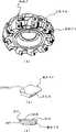
在端铣刀的情况下,如图1(a)中的透视图、图2(a)中的部分剖面的前视图、及图2(b)中放大的局部纵向剖面图所示,可知许多切削镶嵌刀片(在下文中该切削镶嵌刀片称作镶嵌刀片)以给定的间隔可分离地安装在环形刀体的前面。而且还可知该镶嵌刀片具有图1(b)中透视图和图1(c)中纵向截面图所示的形状。In the case of end mills, as shown in the perspective view in Fig. 1(a), the front view in partial section in Fig. 2(a), and the enlarged partial longitudinal section in Fig. 2(b), many Cutting inserts (hereinafter the cutting inserts are referred to as inserts) are detachably mounted in front of the annular cutter body at given intervals. It is also known that the insert insert has the shape shown in the perspective view in Fig. 1(b) and the longitudinal sectional view in Fig. 1(c).
而且,众所周知,由齿面和切削镶嵌刀片的刃线(ridge line)部分侧面所限定的角度(在下文中称作刃线角(ridge line angle))在75°至85°范围内,且该镶嵌刀片以5°至15°的轴向前角(axial rake angle)(刀具本体与轴线的斜角)安装在环形刀体上。Moreover, it is well known that the angle defined by the tooth flanks and the sides of the ridge line portion of the cutting insert (hereinafter referred to as the ridge line angle) is in the range of 75° to 85°, and the ridge line The inserts are mounted on the annular cutter body with an axial rake angle (bevel angle of the cutter body to the axis) of 5° to 15°.
此外,众所周知为了提高金属陶瓷的耐磨损性能,通过化学气相沉积(CVD)工艺或物理气相沉积(PVD)工艺在端面切削镶嵌刀片的金属陶瓷基体表面涂敷厚度为0.5至10μm的硬质涂层。In addition, it is well known that in order to improve the wear resistance of cermets, a hard coating with a thickness of 0.5 to 10 μm is applied on the surface of the cermet substrate of the face cutting insert by chemical vapor deposition (CVD) process or physical vapor deposition (PVD) process. layer.
近年来,切削已经高度需要省工、节能和降低成本,且在端铣切削中渴望高送进速度下的切削。当上述普通的端铣刀用在高送进速度条件下时,平切削刃产生塑性变形。结果,在镶嵌刀片的切削边缘部分将产生很不均匀的磨损,产生缺陷和剥落。因此,镶嵌刀片的使用寿命相对较短。In recent years, cutting has been highly demanded for labor saving, energy saving and cost reduction, and cutting at high feed speed is desired in end mill cutting. When the above-mentioned conventional end mill is used at a high feed rate, the flat cutting edge is plastically deformed. As a result, very uneven wear occurs at the cutting edge portion of the insert insert, resulting in defects and spalling. As a result, insert inserts have a relatively short service life.
在另一种方式中,安装在端铣刀环形刀体上的镶嵌刀片的刃线角减小到65°至75°,和上述普通镶嵌刀片的75°至85°的刃线角成对比,且该镶嵌刀片安装在环形刀体上,从而相对于切削面的倾角减小,也就是,轴向前角,即该镶嵌刀片相对于环形刀体轴线的倾角增加到15°至30°,该倾角比普通镶嵌刀片的5°至15°的轴向前角稍大。当使用上述的刃线角为65°至75°且轴向前角为15°至30°的普通端铣刀进行高送进速度切削时,在镶嵌刀片的切削刃部分产生缺陷和剥落。因此,该镶嵌刀片的使用寿命相对较短。In another mode, the edge line angle of the insert mounted on the annular body of the end mill is reduced to 65° to 75°, as compared to the edge line angle of 75° to 85° of the above-mentioned common insert insert, And the insert insert is installed on the annular cutter body, so that the inclination angle relative to the cutting surface is reduced, that is, the axial rake angle, that is, the inclination angle of the insert insert relative to the axis of the annular cutter body is increased to 15° to 30°, the The inclination angle is slightly larger than the axial rake angle of 5° to 15° for ordinary inserts. When high-feed speed cutting is performed using the above-mentioned conventional end mills having edge line angles of 65° to 75° and axial rake angles of 15° to 30°, defects and spalling occur at the cutting edge portion of the insert insert. Therefore, the insert insert has a relatively short service life.
本发明人已经就在长时间内高送进速度切削时能有满意的切削表面粗糙度的铣削镶嵌刀片在上述普通刀具的基础上进行研究和开发,且已经发现了一种特定的金属陶瓷,它有较高的抗塑性变形能力且不会在切削刃部分产生不均匀的磨损和形成缺陷及剥落(chipping),因此显示出在长时间内的优良切削性能。这种金属陶瓷具有一种芯—壳结构,它包含一芯和一壳(周围区域),且基本上由Ti的碳氮化物和M的混合物组成,其中M是至少一种从Ta、Nb、V、W和Zr中选出的金属。此外金属粘结相包含W-Ni-Co合金,该W-Ni-Co合金含有The inventors of the present invention have conducted research and development on the basis of the above-mentioned general tool for milling inserts capable of satisfactory cutting surface roughness during high-feed speed cutting over a long period of time, and have found a specific cermet, It has high resistance to plastic deformation and does not generate uneven wear and formation of defects and chipping at the cutting edge portion, thus exhibiting excellent cutting performance over a long period of time. This cermet has a core-shell structure comprising a core and a shell (surrounding region) and consists essentially of a mixture of Ti carbonitrides and M, where M is at least one of the compounds selected from Ta, Nb, A metal selected from V, W and Zr. In addition, the metallic binder phase comprises a W-Ni-Co alloy containing
钨(W):以重量计15%-35%Tungsten (W): 15%-35% by weight
镍(Ni):以重量计10%-35%Nickel (Ni): 10%-35% by weight
钴(Co):以重量计35%-70%,Cobalt (Co): 35%-70% by weight,
在高送进速度切削中,端铣刀采用具有减小的0.02-0.08mm珩磨宽度的修光刃,该宽度能保持满意的切削表面粗糙度,该修光刃具有明显的抗塑性变形能力,因此基本不会发生不均匀的磨损。所以,长时间内可保持优良的切削性能且有满意的切削表面粗糙度。In high-feed speed cutting, the end mill adopts a wiper edge with a reduced honing width of 0.02-0.08mm, which can maintain a satisfactory cutting surface roughness, and the wiper edge has obvious resistance to plastic deformation. Therefore, uneven wear hardly occurs. Therefore, excellent cutting performance and satisfactory cutting surface roughness can be maintained for a long time.
当镶嵌刀片以65°至75°的减小的刃线角和15°至30°的轴向前角,也就是相对于切削面的相对小的倾角安装在端铣刀的环形刀体上且当进行高送进速度切削时,在该镶嵌刀片的切削刃部分没有缺陷或剥落,且长时间内保持优良的切削性能。When the insert is installed on the annular cutter body of the end mill with a reduced edge line angle of 65° to 75° and an axial rake angle of 15° to 30°, that is, a relatively small inclination angle with respect to the cutting face and When cutting at a high feed rate, there was no defect or flaking at the cutting edge portion of the insert, and excellent cutting performance was maintained over a long period of time.
当通过化学气相沉积和/或物理气相沉积在端面切削镶嵌刀片的金属陶瓷基体表面涂敷厚度为0.5至10μm的硬质涂层时,在高送进速度切削过程中镶嵌刀片有显著的抗塑性变形能力,因.此基本不发生不均匀的磨损。所以长时间内可保持优良的切削性能且有满意的切削表面粗糙度。When the surface of the cermet substrate of the face cutting insert is coated with a hard coating with a thickness of 0.5 to 10 μm by chemical vapor deposition and/or physical vapor deposition, the insert has a significant resistance to plasticity during cutting at high feed rates Deformation ability, so basically no uneven wear occurs. Therefore, it can maintain excellent cutting performance and have satisfactory cutting surface roughness for a long time.
本发明已经基于上述结果而实现。The present invention has been achieved based on the above results.
一种金属陶瓷,其组织包含一碳氮化物硬质相、一金属粘结相和附带的杂质,其特征在于该金属粘结相包含Co-Ni-W合金,该Co-Ni-W合金含有A cermet whose structure comprises a carbonitride hard phase, a metal binding phase and incidental impurities, characterized in that the metal binding phase comprises a Co-Ni-W alloy, and the Co-Ni-W alloy contains
钨(W):以重量计15%-35%Tungsten (W): 15%-35% by weight
镍(Ni):以重量计10%-35%Nickel (Ni): 10%-35% by weight
钴(Co):以重量计35%-70%,Cobalt (Co): 35%-70% by weight,
其中钨、镍和钴的总量以重量计至少90%。Wherein the total amount of tungsten, nickel and cobalt is at least 90% by weight.
而且,根据该金属陶瓷横截面的显微组织观测该金属陶瓷的特征在于,其组织包含75%至95%面积的碳氮化物硬质相,其余为金属粘结相和附带的杂质的组织。Moreover, the cermet is characterized by observing the microstructure of the cross-section of the cermet in that its structure comprises a carbonitride hard phase of 75% to 95% of the area, and the remainder is a metal binder phase and incidental impurities.
此外,该金属陶瓷的特征在于该碳氮化物硬质相具有一种芯—壳结构,它包含一芯和一壳(周围区域),且基本上由Ti的碳氮化物和M的混合物组成,其中M是至少一种从Ta、Nb、V、W和Zr中选出的金属。Furthermore, the cermet is characterized in that the carbonitride hard phase has a core-shell structure comprising a core and a shell (peripheral region) and consists essentially of a mixture of Ti carbonitrides and M, wherein M is at least one metal selected from Ta, Nb, V, W and Zr.
在采用上述金属陶瓷的用于端面铣削的切削镶嵌刀片中,该切削镶嵌刀片具有一主切削刃和一端切削刃(face cutting edge),主切削刃的珩磨宽度在0.10至0.25mm范围内,修光刃的珩磨宽度为0.02至0.08mm。许多切削镶嵌刀片可分离地安装在环形刀体的前面。这种金属陶瓷镶嵌刀片不会形成粗糙的切削表面且在高送进速度切削中显示出较高的耐磨性。In the cutting insert for face milling using the above-mentioned cermet, the cutting insert has a main cutting edge and a face cutting edge, the honing width of the main cutting edge is in the range of 0.10 to 0.25 mm, the trimming The honing width of the light edge is 0.02 to 0.08mm. A number of cutting inserts are detachably mounted on the front of the ring body. This cermet insert does not form a rough cutting surface and exhibits high wear resistance in cutting at high feed speeds.
在包括一环形刀体和上述切削镶嵌刀片的端铣刀上,切削刃部分的齿面和侧面所限定的角为65°至75°且该切削镶嵌刀片以15°至30°的轴向前角安装在环形刀体上。On an end mill comprising an annular cutter body and the aforementioned cutting insert, the flanks and sides of the cutting edge portion define an angle of 65° to 75° and the cutting insert is forward axially of 15° to 30° The corners are mounted on the ring cutter body.
该切削镶嵌刀片上覆盖有一层硬质涂层,该涂层由化学气相沉积工艺和物理气相沉积工艺中的至少一种工艺形成且平均厚度为0.5至10μm。The cutting insert is covered with a layer of hard coating which is formed by at least one of chemical vapor deposition process and physical vapor deposition process and has an average thickness of 0.5 to 10 μm.
在上述切削镶嵌刀片上,硬质涂层由至少一层由Ti和Al中至少一种元素的氮化物、碳化物、氧化物和碳氮化物组成的涂层组成。On the above-mentioned cutting insert, the hard coating layer consists of at least one coating layer consisting of nitrides, carbides, oxides and carbonitrides of at least one element of Ti and Al.
现在将描述构成本发明的刀具镶嵌刀片的金属陶瓷的成分限制原因。The reason for the limitation of the composition of the cermet constituting the cutting insert of the present invention will now be described.
(a)金属陶瓷碳氮化物硬质相的比例(a) Proportion of cermet carbonitride hard phase
当金属陶瓷硬质相的比例以面积计小于75%时,金属粘结相相对较足,因此不能得到所希望的耐磨性。当比例以面积计超过95%时,烧结能力恶化,因此不能获得所希望的强度。所以比例设定为以面积计75%至95%。When the proportion of the cermet hard phase is less than 75% by area, the metallic binder phase is relatively sufficient, and thus the desired wear resistance cannot be obtained. When the ratio exceeds 95% by area, sinterability deteriorates, and thus desired strength cannot be obtained. So the ratio is set at 75% to 95% by area.
(b)金属陶瓷金属粘结相的成分(b) Composition of cermet-metal binder phase
成分W显著提高金属粘结相的抗塑性变形能力。在成分W以重量计小于15%时,抗塑性变形能力不能提高到所希望的水平。在以重量计大于35%时,金属粘结相的韧性下降,因此在切削刃部分容易发生缺陷和剥落(微缺陷)。所以,成分W以重量计设定为15%至35%。Component W significantly increases the plastic deformation resistance of the metal binder phase. When the component W is less than 15% by weight, the plastic deformation resistance cannot be improved to a desired level. When it is more than 35% by weight, the toughness of the metal binder phase decreases, so that defects and spalling (micro defects) tend to occur at the cutting edge portion. Therefore, the component W is set at 15% to 35% by weight.
成分Ni提高对碳氮化物硬质相的润湿性因而提高了抗剥落性。在成分Ni以重量计小于10%时,抗剥落性不能提高到所希望的水平。在以重量计大于35%时,金属粘结相的强度和抗塑性变形能力下降而容易磨损。因此,成分Ni以重量计设定为10%至35%。The component Ni increases the wettability to the carbonitride hard phase and thus increases the spalling resistance. When the component Ni is less than 10% by weight, the spalling resistance cannot be improved to a desired level. When it is greater than 35% by weight, the strength and plastic deformation resistance of the metal binder phase are reduced to be easily worn. Therefore, the component Ni is set at 10% to 35% by weight.
成分Co提高烧结能力因而提高了铣削镶嵌刀片的强度。在成分Co以重量计小于35%时,强度不能提高到所希望的水平。在以重量计大于70%时,抗塑性变形能力趋于下降。因此,成分Co以重量计设定为35%至70%。The component Co increases the sinterability and thus the strength of the milling insert. When the component Co is less than 35% by weight, the strength cannot be increased to a desired level. At more than 70% by weight, the plastic deformation resistance tends to decrease. Therefore, the component Co is set at 35% to 70% by weight.
当W、Ni和Co的总量以重量计小于90%时,金属粘结相的强度迅速下降,因此在切削刃部分容易发生缺陷和剥落。所以,W、Ni和Co的总量以重量计设定为90%或更高。When the total amount of W, Ni and Co is less than 90% by weight, the strength of the metal binder phase rapidly decreases, so that defects and spalling easily occur at the cutting edge portion. Therefore, the total amount of W, Ni and Co is set to 90% by weight or higher.
(c)珩磨宽度(c) Honing width
珩磨用来提高切削刃的稳定性,且修光刃的珩磨宽度最好是减小,以便改进被切削工件的表面粗糙度。因为在金属粘结相中的成分W显著提高了粘结相的抗塑性变形能力,当切削刃部分尤其是修光刃的珩磨宽度减小到0.08mm或更小时,在高送进速度切削中不会发生导致不均匀磨损的塑性变形。当修光刃的珩磨宽度小于0.02mm时,切削刃的稳定性下降,导致缺陷和剥落。当珩磨宽度超过0.08mm时,切削工件的表面粗糙度下降。因此,修光刃的珩磨宽度设定为0.02至0.08mm。主切削刃的珩磨宽度在常规范围内,也就是0.10至0.25mm。Honing is used to improve the stability of the cutting edge, and the honing width of the wiper edge is preferably reduced in order to improve the surface roughness of the workpiece being cut. Because the component W in the metal binder phase significantly improves the plastic deformation resistance of the binder phase, when the honing width of the cutting edge part, especially the wiper edge, is reduced to 0.08mm or less, in high feed speed cutting Plastic deformation that would cause uneven wear does not occur. When the honing width of the wiper edge is less than 0.02 mm, the stability of the cutting edge decreases, resulting in defects and spalling. When the honing width exceeds 0.08mm, the surface roughness of the cut workpiece decreases. Therefore, the honing width of the wiper blade is set to be 0.02 to 0.08 mm. The honing width of the main cutting edge is in the conventional range, that is, 0.10 to 0.25 mm.
(d)端铣刀的轴向前角和刃线角(d) Axial rake angle and edge line angle of end mill
在本发明的端铣刀上,当在高送进速度、高速切削条件下进行铣削时,该镶嵌刀片的刃线角和由安装的镶嵌刀片和刀体所限定的轴向前角必然确定。当镶嵌刀片的刃线角超过75°或当轴向前角小于15°(这些是常规镶嵌刀片的值),不能进行高送进速度的高速切割。当镶嵌刀片的刃线角小于65°或当轴向前角超过30°时,在高送进速度的高速切削中镶嵌刀片的切削刃部分易于产生缺陷。On the end mill of the present invention, when milling under high feed rate, high speed cutting conditions, the edge line angle of the insert and the axial rake angle defined by the mounted insert and cutter body are necessarily determined. When the edge line angle of the mosaic blade exceeds 75° or the rake angle of the current axis is less than 15° (these are the values of conventional mosaic blades), high-speed cutting with high feed speed cannot be performed. When the edge line angle of the insert is less than 65° or when the axial rake angle exceeds 30°, the cutting edge portion of the insert is prone to defects in high-speed cutting at high feed speed.
(e)硬质涂层(e) Hard coating
硬质涂层至少包括一层Ti和/或Al的氮化物、碳化物、氧化物和碳氮化物。当其平均厚度小于0.5μm时,不能确保所希望的耐磨性。当平均厚度超过10μm时,在切削刃上容易产生缺陷和剥落。因此,平均厚度设定为0.5至10μm。The hard coating includes at least one layer of Ti and/or Al nitrides, carbides, oxides and carbonitrides. When the average thickness thereof is less than 0.5 μm, desired wear resistance cannot be ensured. When the average thickness exceeds 10 μm, defects and peeling tend to occur on the cutting edge. Therefore, the average thickness is set at 0.5 to 10 μm.
现在将参照下述实施例详细描述本发明的端铣刀。The end mill of the present invention will now be described in detail with reference to the following examples.
实施例1Example 1
对于形成硬质相的粉末状原材料,以预定的平均粒度在1至2μm之间来准备一种具有以原子百分比计成分为(Ti0.9Ta0.1)C0.7N0.3的Ti和Ta的碳氮化物的粉末状混合物、一种具有以原子百分比计成分为(Ti0.9Nb0.1)C0.7N0.3的Ti和Nb的碳氮化物的粉末状混合物,一种具有以原子百分比计成分为(Ti0.8Ta0.1Zr0.1)C0.5N0.5的Ti、Ta和Zr的碳氮化物的粉末状混合物,一种具有以原子百分比计成分为TiC0.5N0.5的Ti的碳氮化物的粉末状混合物,一种具有以原子百分比计成分为(Ti0.7W0.2Nb0.1)C0.4N0.6的Ti、W和Nb的碳氮化物的粉末状混合物,一种具有以原子百分比计成分为(Ti0.9V0.1)C0.6N0.4的Ti和V的碳氮化物的粉末状混合物,一种具有以原子百分比计成分为(Ti0.8V0.1Zr0.1)C0.7N0.3的Ti、V和Zr的碳氮化物的粉末状混合物,一种具有以原子百分比计成分为(Ti0.7Zr0.3)C0.5N0.5的Ti和Zr的碳氮化物的粉末状混合物,一种具有以原子百分比计成分为(Ti0.8Ta0.1Nb0.1)C0.7N0.3的Ti、Ta和Nb的碳氮化物的粉末状混合物,一种具有以原子百分比计成分为(Ti0.7Ta0.1V0.1W0.1)C0.6N0.4的Ti、Ta、V和W的碳氮化物的粉末状混合物。且以平均粒度在1至2μm范围内准备TiN粉末、ZrC粉末、TaC粉末、Nbc粉末和WC粉末。对于形成粘结相的粉末状原材料,准备W粉末、Ni粉末和Co粉末。这些粉末状粘结材料的平均粒度在1至2μm的范围内。For the powdery raw material forming the hard phase, a carbonitride of Ti and Ta having a composition in atomic percent of (Ti0.9 Ta0.1 )C0.7 N0.3 is prepared with a predetermined average particle size between 1 and 2 μm A powdery mixture of Ti and Nb carbonitrides having the atomic percent composition of (Ti0.9 Nb0.1 )C0.7 N0.3 , a powdery mixture of Ti and Nb carbonitrides having the atomic percent composition of (Ti0.8 Ta0.1 Zr0.1 ) Powdery mixture of Ti, Ta and Zr carbonitrides of C0.5 N0.5 , a powdery mixture of Ti carbonitrides having the composition TiC0.5 N0.5 in atomic percent, a powdery mixture of Ti carbonitrides having Powdered mixture of carbonitrides of Ti, W and Nb having the atomic percent composition (Ti0.7 W0.2 Nb0.1 )C0.4 N0.6 , one having the atomic percent composition (Ti0.9 V0.1 )C0.6 Powdery mixture of carbonitrides of Ti and V with N0.4 , a powdery mixture of carbonitrides of Ti, V and Zr having the composition in atomic percent (Ti0.8 V0.1 Zr0.1 )C0.7 N0.3 , a powdery mixture of Ti and Zr carbonitrides having the atomic percent composition (Ti0.7 Zr0.3 )C0.5 N0.5 , and one having the atomic percent composition (Ti0.8 Ta0.1 Nb0.1 ) Powdery mixture of C0.7 N0.3 Ti, Ta and Nb carbonitrides, a Ti, Ta, V and W having the composition in atomic percent of (Ti0.7 Ta0.1 V0.1 W0.1 ) C0.6 N0.4 Powdered mixture of carbonitrides. And TiN powder, ZrC powder, TaC powder, Nbc powder and WC powder were prepared with an average particle size in the range of 1 to 2 μm. For powdery raw materials forming the binder phase, W powder, Ni powder, and Co powder were prepared. The average particle size of these powdery binding materials is in the range of 1 to 2 μm.
这些原材料在表1和2所示的组成基础上混合,并在球磨机中湿式混合72小时。每种混合物都在15kgf/mm2的压力下干燥和模压,以形成一压坯。该压坯在一真空环境下以2℃/min的加热速度加热到1500℃,在减小的压力为10乇的氮气气氛中在1500℃保持1小时进行烧结,然后冷却。每一切削刃部分的主切削刃和修光刃都要经过表3或4所示的珩磨,其中主切削刃的珩磨宽度为一普通值,而修光刃的珩磨宽度小于普通值。因此制备了本发明的用于端铣工具的铣削镶嵌刀片(类型1至10)和用于对比的铣削镶嵌刀片类型1至10。每一铣削镶嵌刀片具有SEEN1203AFTN1(刃线角:70°)的形状。These raw materials were mixed based on the compositions shown in Tables 1 and 2, and wet mixed in a ball mill for 72 hours. Each mixture was dried and molded under a pressure of 15 kgf/mm2 to form a compact. The compact was heated to 1500°C at a heating rate of 2°C/min in a vacuum atmosphere, kept at 1500°C for 1 hour in a reduced-pressure nitrogen atmosphere of 10 Torr for sintering, and then cooled. The main cutting edge and wiper edge of each cutting edge portion are honed as shown in Table 3 or 4, wherein the honing width of the main cutting edge is a normal value, and the honing width of the wiper edge is less than the normal value. Milling inserts for end milling tools according to the invention (types 1 to 10) and milling inserts types 1 to 10 for comparison were thus prepared. Each milling insert had a shape of SEEN1203AFTN1 (edge line angle: 70°).
在用于对比的铣削镶嵌刀片(类型1至10)中,在每种金属陶瓷的粘结相中W的含量以重量计为7%或更低或者该粘结相不含W。In the milling inserts (types 1 to 10) used for comparison, the content of W in the binder phase of each cermet was 7% by weight or less or the binder phase contained no W.
通过电子扫描显微镜观察到每一铣削镶嵌刀片的任意横截面的组织,且通过采用一种图像分析仪从观测到的图像确定组织中具有芯—壳结构的硬质相比例,如表3和4中所示。The structure of any cross-section of each milling insert was observed by a scanning electron microscope, and the proportion of the hard phase with a core-shell structure in the structure was determined from the observed image by using an image analyzer, as shown in Tables 3 and 4 shown in .
在构成镶嵌刀片的金属陶瓷的粘结相中以重量计的W、Ni和Co含量通过湿法分析工艺而确定,如表3和4中所示。The W, Ni and Co contents by weight in the binder phase of the cermet constituting the insert were determined by a wet analysis process, as shown in Tables 3 and 4.
每种类型的一个铣削镶嵌刀片用螺栓固定在端面直径为200mm的刀具前面,如图1(a)所示形成轴向前角为20°的端铣刀,且在下述状态下采用该端铣刀使碳钢经受干燥的、高速送进的铣削测试,来确定直到刀具到达其使用寿命终点的切削持续时间:One milling insert of each type is bolted in front of a tool with a face diameter of 200 mm to form an end mill with an axial rake angle of 20° as shown in Fig. 1(a), and the end mill is used in the following state The knife subjects carbon steel to a dry, high-feed milling test to determine the duration of cut until the tool reaches the end of its useful life:
被切削工件:日本工业标准(JIS)S45C板Workpiece to be cut: Japanese Industrial Standard (JIS) S45C plate
切削速度:250m/minCutting speed: 250m/min
切削深度:2.5mmCutting depth: 2.5mm
送进速度:0.4mm/齿Feed speed: 0.4mm/tooth
从切削开始一分钟后测量切削工件的表面粗糙度。表面粗糙度Rz在1.9-2.8范围内,处于相当满意的水平。The surface roughness of the cut workpiece was measured one minute from the start of cutting. The surface roughness Rz is in the range of 1.9-2.8, which is quite satisfactory.
表1至4中所示的结果表明,每种具有本发明的铣削镶嵌刀片(类型1至10)的端铣刀在采用具有减小的0.02至0.08mm珩磨宽度的修光刃的高速送进切削中表现出较高的抗塑性变形能力,其中珩磨宽度较小是为了保持满意的切削表明粗糙度,且长时间内保持优良的切削性能,因为在该金属陶瓷的粘结相中有较高的W含量。相反,由于在采用具有减小的珩磨宽度的修光刃的高速送进切削中的塑性变形,每种具有用于对比的铣削镶嵌刀片(类型1至10)的端铣刀表现出不均匀的磨损,且因为在该金属陶瓷的粘结相中不含有W或含有以重量计至多7%的W,这不足以保持所希望的抗塑性变形能力,而具有相对短的使用寿命。The results shown in Tables 1 to 4 show that each of the end mills having milling inserts of the present invention (types 1 to 10) performed at a high speed feed using a wiper edge with a reduced honing width of 0.02 to 0.08 mm. It shows high resistance to plastic deformation in cutting, and the honing width is small to maintain satisfactory cutting surface roughness, and maintain excellent cutting performance for a long time, because there is a high The W content. In contrast, each of the end mills with the milling inserts (types 1 to 10) used for comparison showed non-uniform wear, and since no W or up to 7% by weight of W is contained in the binder phase of the cermet, which is insufficient to maintain the desired resistance to plastic deformation, it has a relatively short service life.
表1
表2
表3
表4
实施例2Example 2
对于形成硬质相的粉末状原材料,以预定的平均粒度在1至2μm范围内来准备一种具有以原子百分比计成分为(Ti0.9Ta0.1)C0.7N0.3的Ti和Ta的碳氮化物的粉末状混合物、一种具有以原子百分比计成分为(Ti0.9Nb0.1)C0.7N0.3的Ti和Nb的碳氮化物的粉末状混合物、一种具有以原子百分比计成分为(Ti0.8Ta0.1Zr0.1)C0.5N0.5的Ti、Ta和Zr的碳氮化物的粉末状混合物、一种具有以原子百分比计成分为TiC0.5N0.5的Ti的碳氮化物的粉末状混合物、一种具有以原子百分比计成分为(Ti0.7W0.2Nb0.1)C0.4N0.6的Ti、W和Nb的碳氮化物的粉末状混合物、一种具有以原子百分比计成分为(Ti0.9V0.1)C0.6N0.4的Ti和V的碳氮化物的粉末状混合物、一种具有以原子百分比计成分为(Ti0.8V0.1Zr0.1)C0.7N0.3的Ti、V和Zr的碳氮化物的粉末状混合物、一种具有以原子百分比计成分为(Ti0.7Zr0.3)C0.5N0.5的Ti和Zr的碳氮化物的粉末状混合物、一种具有以原子百分比计成分为(Ti0.8Ta0.1Nb0.1)C0.7N0.3的Ti、Ta和Nb的碳氮化物的粉末状混合物、一种具有以原子百分比计成分为(Ti0.7Ta0.1V0.1W0.1)C0.6N0.4的Ti、Ta、V和W的碳氮化物的粉末状混合物。且以平均粒度在1至2μm范围内准备TiN粉末、ZrC粉末、TaC粉末、Nbc粉末和WC粉末。对于形成粘结相的粉末状原材料,准备W粉末、Ni粉末和Co粉末。这些粉末状粘结材料的平均粒度在1至2μm的范围内。For the powdery raw material forming the hard phase, a carbonitride of Ti and Ta having a composition in atomic percent of (Ti0.9 Ta0.1 )C0.7 N0.3 is prepared with a predetermined average particle size in the range of 1 to 2 μm A powdery mixture of Ti and Nb carbonitrides having the atomic percent composition of (Ti0.9 Nb0.1 )C0.7 N0.3 , a powdery mixture of Ti and Nb carbonitrides having the atomic percent composition of (Ti0.8 Ta0.1 Zr0.1 ) C0.5 N0.5 Ti, Ta and Zr carbonitride powder mixture, a Ti carbonitride powder mixture having the composition TiC0.5 N0.5 in atomic percent, a powder mixture having A powdery mixture of carbonitrides of Ti, W and Nb having the atomic percent composition (Ti0.7 W0.2 Nb0.1 )C0.4 N0.6 , one having the atomic percent composition (Ti0.9 V0.1 )C0.6 Powdery mixture of carbonitrides of Ti and V with N0.4 , a powdery mixture of carbonitrides of Ti, V and Zr with the atomic percent composition (Ti0.8 V0.1 Zr0.1 )C0.7 N0.3 , a powdery mixture of Ti and Zr carbonitrides having the atomic percent composition (Ti0.7 Zr0.3 )C0.5 N0.5 , and a powdery mixture having the atomic percent composition (Ti0.8 Ta0.1 Nb0.1 ) Powdery mixture of carbonitrides of Ti, Ta and Nb with C0.7 N0.3 , a Ti, Ta, V and W having the composition in atomic percent of (Ti0.7 Ta0.1 V0.1 W0.1 ) C0.6 N0.4 Powdered mixture of carbonitrides. And TiN powder, ZrC powder, TaC powder, Nbc powder and WC powder were prepared with an average particle size in the range of 1 to 2 μm. For powdery raw materials forming the binder phase, W powder, Ni powder, and Co powder were prepared. The average particle size of these powdery binding materials is in the range of 1 to 2 μm.
这些原材料在表5和6所示的组成基础上混合,并在球磨机中湿式混合72小时。每种混合物都在15kgf/mm2的压力下干燥和模压,以形成一压坯。该压坯在一真空环境下以2℃/min的加热速度加热到1550℃,在减小的压力为5乇的氮气气氛中在1550℃保持1.5小时进行烧结,然后冷却。每一切削刃部分的主切削刃和修光刃都要经过珩磨,从而主切削刃和修光刃的珩磨宽度分别为0.20mm和0.15mm。因此制备了本发明的用于端铣刀的铣削镶嵌刀片(类型1至10)和用于对比的铣削镶嵌刀片。每一铣削镶嵌刀片具有SEEN1203AFTN1的形状且刃线角如表7和8所示。These raw materials were mixed based on the compositions shown in Tables 5 and 6, and wet mixed in a ball mill for 72 hours. Each mixture was dried and molded under a pressure of 15 kgf/mm2 to form a compact. The compact was heated to 1550°C at a heating rate of 2°C/min in a vacuum atmosphere, kept at 1550°C for 1.5 hours in a reduced-pressure nitrogen atmosphere of 5 Torr for sintering, and then cooled. The main cutting edge and the wiper edge of each cutting edge portion were honed so that the honing widths of the main cutting edge and the wiper edge were 0.20 mm and 0.15 mm, respectively. Milling inserts (types 1 to 10) of the present invention for end mills and milling inserts for comparison were thus prepared. Each milling insert had the shape of SEEN1203AFTN1 and the edge angles are shown in Tables 7 and 8.
在用于对比的铣削镶嵌刀片(类型1至10)中,粘结相中含有以重量计为7%或更低的W或者不含W。In the milling inserts (Types 1 to 10) used for comparison, W was contained in the binder phase at 7% by weight or less or was not contained.
通过电子扫描显微镜观察到每一铣削镶嵌刀片的任意横截面的组织,采用一种图像分析仪从观测到的图像中确定组织中具有芯—壳结构的硬质相比例,如表7和8中所示。Observe the structure of any cross-section of each milling mosaic insert through a scanning electron microscope, and use an image analyzer to determine the hard phase ratio with a core-shell structure in the structure from the observed image, as shown in Tables 7 and 8. shown.
在构成该镶嵌刀片的金属陶瓷的粘结相中以重量计的W、Ni和Co的含量通过湿法分析工艺而确定,如表7和8中所示。The contents of W, Ni and Co by weight in the binder phase of the cermet constituting the insert were determined by a wet analysis process, as shown in Tables 7 and 8.
每种类型的十个铣削镶嵌刀片用螺栓固定在端面直径为200mm的刀具前面,如图1(a)所示形成端铣刀,且在下述状态下采用该端铣刀使合金钢经受干燥的、高速送进的铣削测试,来确定侧面磨损的最大宽度:Ten milling inserts of each type were bolted in front of a tool with a face diameter of 200 mm to form an end mill as shown in Fig. 1(a), and the alloy steel was subjected to drying in the following state , high-feed milling test to determine the maximum width of flank wear:
被切削工件:日本工业标准(JIS)SCM440板Workpiece to be cut: Japanese Industrial Standard (JIS) SCM440 plate
切削速度:350m/minCutting speed: 350m/min
切削深度:2mmCutting depth: 2mm
送进速度:0.4mm/齿Feed speed: 0.4mm/tooth
时间:20分钟Time: 20 minutes
十个宽度的平均值在表7和8中示出。The average values of the ten widths are shown in Tables 7 and 8.
表5至8中所示的结果表明,每种具有本发明铣削镶嵌刀片(类型1至10)的端铣刀在镶嵌刀片的刃线角度较低、镶嵌刀片对刀具本体的轴向前角相对较低的高速送进切削中没有产生缺陷,也没有在切削刃部分剥落,并保持了优良的切削性能,因为在构成该镶嵌刀片的金属陶瓷的硬质相是特定的,且该金属陶瓷的粘结相中有较高的W含量。相反,每种具有用于对比的铣削镶嵌刀片(类型1至10)的端铣刀表现出不良的耐热性和不良的抗塑性变形能力,且在高温下不能保持粘结相的理想强度,尽管该金属陶瓷具有与本发明镶嵌刀片相同类型的硬磁相,因为在该金属陶瓷的粘结相中不含有W或含有以重量计至多7%的W。结果,在切削刃部分产生缺陷和剥落,而该镶嵌刀片的使用寿命相对较短。The results shown in Tables 5 to 8 show that each of the end mills having the milling inserts of the present invention (types 1 to 10) had a lower edge line angle of the insert and a relatively opposite axial rake angle of the insert to the tool body. No defects were generated in the lower high-speed feed cutting, and there was no peeling off at the cutting edge, and excellent cutting performance was maintained because the hard phase of the cermet constituting the insert was specific, and the cermet There is a higher W content in the binder phase. In contrast, each of the end mills with milling inserts (types 1 to 10) used for comparison exhibited poor heat resistance and poor resistance to plastic deformation, and could not maintain the desired strength of the binder phase at high temperatures, Although the cermet has the same type of hard magnetic phase as the insert of the present invention, since no W is contained or up to 7% by weight of W is contained in the binder phase of the cermet. As a result, defects and spalling occur at the cutting edge portion, and the service life of the insert is relatively short.
表5
表6
表7
表8
实施例3Example 3
对于形成硬质相的粉末状原材料,以预定的平均粒度在1至2μm范围内来准备一种具有以原子百分比计成分为(Ti0.9Ta0.1)C0.7N0.3的Ti和Ta的碳氮化物的粉末状混合物、一种具有以原子百分比计成分为(Ti0.9Nb0.1)C0.7N0.3的Ti和Nb的碳氮化物的粉末状混合物、一种具有以原子百分比计成分为(Ti0.8Ta0.1Zr0.1)C0.5N0.5的Ti、Ta和Zr的碳氮化物的粉末状混合物、一种具有以原子百分比计成分为TiC0.5N0.5的Ti的碳氮化物的粉末状混合物、一种具有以原子百分比计成分为(Ti0.7W0.2Nb0.1)C0.4N0.6的Ti、W和Nb的碳氮化物的粉末状混合物、一种具有以原子百分比计成分为(Ti0.9V0.1)C0.6N0.4的Ti和V的碳氮化物的粉末状混合物、一种具有以原子百分比计成分为(Ti0.8V0.1Zr0.1)C0.7N0.3的Ti、V和Zr的碳氮化物的粉末状混合物、一种具有以原子百分比计成分为(Ti0.7Zr0.3)C0.5N0.5的Ti和Zr的碳氮化物的粉末状混合物、一种具有以原子百分比计成分为(Ti0.8Ta0.1Nb0.1)C0.7N0.3的Ti、Ta和Nb的碳氮化物的粉末状混合物、一种具有以原子百分比计成分为(Ti0.7Ta0.1V0.1W0.1)C0.6N0.4的Ti、Ta、V和W的碳氮化物的粉末状混合物。且以平均粒度在1至2um范围内准备TiN粉末、ZrC粉末、TaC粉末、Nbc粉末和WC粉末。对于形成粘结相的粉末状原材料,准备W粉末、Ni粉末和Co粉末。这些粉末状粘结材料的平均粒度在1至2μm的范围内。For the powdery raw material forming the hard phase, a carbonitride of Ti and Ta having a composition in atomic percent of (Ti0.9 Ta0.1 )C0.7 N0.3 is prepared with a predetermined average particle size in the range of 1 to 2 μm A powdery mixture of Ti and Nb carbonitrides having the atomic percent composition of (Ti0.9 Nb0.1 )C0.7 N0.3 , a powdery mixture of Ti and Nb carbonitrides having the atomic percent composition of (Ti0.8 Ta0.1 Zr0.1 ) A powdery mixture of Ti, Ta and Zr carbonitrides of C0.5 N0.5 , a powdery mixture of Ti carbonitrides having the composition TiC0.5 N0.5 in atomic percent, a powdery mixture of Ti carbonitrides with A powdery mixture of carbonitrides of Ti, W and Nb having the atomic percent composition (Ti0.7 W0.2 Nb0.1 )C0.4 N0.6 , one having the atomic percent composition (Ti0.9 V0.1 )C0.6 Powdery mixture of carbonitrides of Ti and V with N0.4 , a powdery mixture of carbonitrides of Ti, V and Zr with the atomic percent composition (Ti0.8 V0.1 Zr0.1 )C0.7 N0.3 , a powdery mixture of Ti and Zr carbonitrides having the atomic percent composition (Ti0.7 Zr0.3 )C0.5 N0.5 , and a powdery mixture having the atomic percent composition (Ti0.8 Ta0.1 Nb0.1 ) Powdery mixture of carbonitrides of Ti, Ta and Nb with C0.7 N0.3 , a Ti, Ta, V and W having the composition in atomic percent of (Ti0.7 Ta0.1 V0.1 W0.1 ) C0.6 N0.4 Powdered mixture of carbonitrides. And TiN powder, ZrC powder, TaC powder, Nbc powder and WC powder were prepared with an average particle size in the range of 1 to 2 um. For powdery raw materials forming the binder phase, W powder, Ni powder, and Co powder were prepared. The average particle size of these powdery binding materials is in the range of 1 to 2 μm.
这些原材料在表9和10所示的组成基础上混合,并在球磨机中湿式混合72小时。每种混合物都在15kgf/mm2的压力下干燥和模压,以形成一压坯。该压坯在真空环境下以2℃/min的加热速度加热到1550℃,在减小的压力为5乇的氮气气氛中在1550℃保持1.5小时进行烧结,然后冷却。每一切削刃部分的主切削刃和修光刃都要经过如表11和12所示的珩磨,其中主切削刃的珩磨宽度是一普通值,而平切削刃的珩磨宽度小于该普通值。因此制备了本发明的用于端铣刀的金属陶瓷基体(类型A至J)和用于对比的铣削镶嵌刀片(类型a至j)。每一金属陶瓷基体具有SEEN1203AFTN1的形状。These raw materials were mixed based on the compositions shown in Tables 9 and 10, and wet mixed in a ball mill for 72 hours. Each mixture was dried and molded under a pressure of 15 kgf/mm2 to form a compact. The compact was heated to 1550°C at a heating rate of 2°C/min in a vacuum atmosphere, kept at 1550°C for 1.5 hours in a reduced-pressure nitrogen atmosphere of 5 Torr for sintering, and then cooled. The main cutting edge and wiper edge of each cutting edge portion were honed as shown in Tables 11 and 12, wherein the honing width of the main cutting edge was a normal value, and the honing width of the flat cutting edge was smaller than the normal value. Cermet substrates for end mills according to the invention (types A to J) and milling inserts for comparison (types a to j) were thus prepared. Each cermet substrate has the shape of SEEN1203AFTN1.
在用于对比的金属陶瓷基体(类型a至j)中,粘结相中含有以重量计为7%或更低的W或者不含W。In the comparative cermet substrates (types a to j), the binder phase contained 7% by weight or less of W or no W.
每一金属陶瓷基体的任意横截面的组织通过电子扫描显微镜观察,且组织中具有芯—壳结构的硬质相比例采用图像分析仪从观测到的图像中确定,如表11和12中所示。The structure of any cross-section of each cermet matrix is observed by a scanning electron microscope, and the proportion of the hard phase with a core-shell structure in the structure is determined from the observed images by an image analyzer, as shown in Tables 11 and 12 .
在金属陶瓷基体的粘结相中以重量计的W、Ni和Co的含量通过湿法分析工艺而确定,如表11和12中所示。The contents of W, Ni and Co by weight in the binder phase of the cermet matrix were determined by a wet analysis process, as shown in Tables 11 and 12.
这些金属陶瓷基体(本发明的类型A至J和用于对比的a至j)在丙酮中进行超声波清洗,干燥,并通过表13和14中所示的方法涂敷。一层具有表13或14中示出的设定成分和厚度的硬质涂层在每一金属涂层基体上形成。因此制备出用于端铣刀的本发明的涂层镶嵌刀片(类型1至10)和用于对比的涂层镶嵌刀片(类型1至10)。These cermet substrates (types A to J according to the invention and a to j for comparison) were ultrasonically cleaned in acetone, dried and coated by the methods shown in Tables 13 and 14. A hard coat layer having the set composition and thickness shown in Table 13 or 14 was formed on each metallic coating substrate. Coated inserts of the invention (types 1 to 10) for end mills and coated inserts (types 1 to 10) for comparison were thus prepared.
每一涂层镶嵌刀片的硬质涂层的横截面通过电子扫描显微镜进行观测,确定其成分和平均厚度。该成分和平均厚度基本上等于表13和14中示出的设定的成分和平均厚度。The cross-section of the hard coating of each coated insert was observed by scanning electron microscopy to determine its composition and average thickness. The composition and average thickness are substantially equal to the set composition and average thickness shown in Tables 13 and 14.
每种类型的一个铣削镶嵌刀片用螺栓固定在端面直径为200mm的刀具的前面,如图1(a)所示形成端铣刀,且在下述状态下采用该端铣刀使合金钢经受干燥的、高速送进的铣削测试,来确定直到刀具到达其使用寿命的切削持续时间:One milling insert of each type was bolted to the front of a tool having a face diameter of 200 mm to form an end mill as shown in Fig. 1(a), and the alloy steel was subjected to drying in the following state using the end mill , high-feed milling test to determine the duration of cut until the tool reaches the end of its useful life:
被切削工件:日本工业标准(JIS)SNCM439板Workpiece to be cut: Japanese Industrial Standard (JIS) SNCM439 plate
切削速度:350m/minCutting speed: 350m/min
切削深度:1.5mmCutting depth: 1.5mm
送进速度:0.5mm/齿Feed speed: 0.5mm/tooth
从切削开始一分钟之后测量切削工件的表面粗糙度。表面粗糙度Rz在1.9-2.8范围内,处于相当满意的水平。The surface roughness of the cut workpiece was measured after one minute from the start of cutting. The surface roughness Rz is in the range of 1.9-2.8, which is quite satisfactory.
表9至14中所示的结果表明,每种具有本发明铣削镶嵌刀片(类型1至10)的端铣刀在采用具有减小的0.02至0.08mm珩磨宽度的平切削刃的高速送进切削中表现出较高的抗塑性变形能力,其中珩磨宽度较小是为了保持满意的切削表明粗糙度,且长时间内保持了优良的切削性能,因为在该金属陶瓷的粘结相中有较高的W含量。相反,每种具有用于对比的铣削镶嵌刀片(类型1至10)的端铣刀,在采用具有减小的珩磨宽度的平切削刃的高速送进切削中由于塑性变形表现出不均匀的磨损,而具有相对短的使用寿命,因为在该金属陶瓷的粘结相中不含有W或含有以重量计至多7%的W,这不足以保持所希望的抗塑性变形能力。The results shown in Tables 9 to 14 show that each end mill with the milling inserts of the present invention (types 1 to 10) performed at high feed cutting speeds using a flat cutting edge with a reduced honing width of 0.02 to 0.08 mm. It shows a high resistance to plastic deformation, and the honing width is small in order to maintain a satisfactory cutting surface roughness, and maintain excellent cutting performance for a long time, because there is a high The W content. In contrast, each of the end mills with the milling inserts used for comparison (types 1 to 10) exhibited uneven wear due to plastic deformation during high-feed cutting with a flat cutting edge with a reduced honing width , and has a relatively short service life, because the binder phase of the cermet does not contain W or contains up to 7% by weight of W, which is not enough to maintain the desired resistance to plastic deformation.
表9
表10
表11
表12
表13
表14
Claims (7)
Translated fromChineseApplications Claiming Priority (6)
| Application Number | Priority Date | Filing Date | Title |
|---|---|---|---|
| JP97647/1999 | 1999-04-05 | ||
| JP11097647AJP2000288820A (en) | 1999-04-05 | 1999-04-05 | Face milling tool showing high speed feed cutting and superior wear resistance without decreasing roughness of cut face |
| JP118013/1999 | 1999-04-26 | ||
| JP11801399AJP2000308915A (en) | 1999-04-26 | 1999-04-26 | Face milling tool displaying excellent wear resistance without deteriorating cut surface roughness in high feed cutting |
| JP11204083AJP2001030108A (en) | 1999-07-19 | 1999-07-19 | Front milling tool displaying excellent defect resistance of throwaway tip in high feeding and speed cutting |
| JP204083/1999 | 1999-07-19 |
Publications (2)
| Publication Number | Publication Date |
|---|---|
| CN1274761Atrue CN1274761A (en) | 2000-11-29 |
| CN1117168C CN1117168C (en) | 2003-08-06 |
Family
ID=27308461
Family Applications (1)
| Application Number | Title | Priority Date | Filing Date |
|---|---|---|---|
| CN00117605AExpired - LifetimeCN1117168C (en) | 1999-04-05 | 2000-04-05 | Cutting insert blade for metallic ceramic |
Country Status (3)
| Country | Link |
|---|---|
| EP (1) | EP1043414B1 (en) |
| CN (1) | CN1117168C (en) |
| DE (1) | DE60006017T2 (en) |
Cited By (4)
| Publication number | Priority date | Publication date | Assignee | Title |
|---|---|---|---|---|
| CN106001725A (en)* | 2016-05-30 | 2016-10-12 | 方雪锋 | High-speed milling cutter of transmission shaft spline shaft |
| CN106834809A (en)* | 2015-12-04 | 2017-06-13 | 南京理工大学 | A kind of high-performance carbide using cobalt-base alloys as Binder Phase |
| CN107109905A (en)* | 2015-01-14 | 2017-08-29 | 三菱综合材料株式会社 | Excavation blade and excavating bur |
| CN107635702A (en)* | 2015-06-26 | 2018-01-26 | 三菱综合材料株式会社 | Surface-coated cutting tool |
Families Citing this family (3)
| Publication number | Priority date | Publication date | Assignee | Title |
|---|---|---|---|---|
| CN103282147B (en)* | 2010-12-25 | 2014-10-08 | 京瓷株式会社 | Cutting tool |
| DE102016111805A1 (en) | 2016-06-28 | 2017-12-28 | Komet Group Gmbh | Cutting machine tool, in particular machine driving tool |
| CN108637338A (en)* | 2018-05-21 | 2018-10-12 | 浙江普菲特切削工具有限公司 | A kind of Strengthening and Toughening cermet material and the slotting cutter being made from it |
Family Cites Families (6)
| Publication number | Priority date | Publication date | Assignee | Title |
|---|---|---|---|---|
| DE2420768A1 (en)* | 1973-06-18 | 1975-01-09 | Teledyne Ind | CARBONITRIDE ALLOYS FOR CUTTING TOOLS AND WEAR PARTS |
| JP2775955B2 (en)* | 1990-01-31 | 1998-07-16 | 三菱マテリアル株式会社 | Manufacturing method of coating cermet with excellent wear resistance |
| JP3198680B2 (en)* | 1992-11-16 | 2001-08-13 | 三菱マテリアル株式会社 | Cutting tools made of Ti-based carbonitride-based cermet with excellent wear resistance |
| US5374471A (en)* | 1992-11-27 | 1994-12-20 | Mitsubishi Materials Corporation | Multilayer coated hard alloy cutting tool |
| JP2616655B2 (en)* | 1993-03-08 | 1997-06-04 | 三菱マテリアル株式会社 | Titanium carbonitride-based cermet cutting tool with excellent wear resistance |
| US5672031A (en)* | 1995-05-12 | 1997-09-30 | Kennametal Inc. | Milling cutter |
- 2000
- 2000-04-05CNCN00117605Apatent/CN1117168C/ennot_activeExpired - Lifetime
- 2000-04-05EPEP00107084Apatent/EP1043414B1/ennot_activeExpired - Lifetime
- 2000-04-05DEDE60006017Tpatent/DE60006017T2/ennot_activeExpired - Lifetime
Cited By (7)
| Publication number | Priority date | Publication date | Assignee | Title |
|---|---|---|---|---|
| CN107109905A (en)* | 2015-01-14 | 2017-08-29 | 三菱综合材料株式会社 | Excavation blade and excavating bur |
| US10465448B2 (en) | 2015-01-14 | 2019-11-05 | Mitsubishi Materials Corporation | Drill bit insert and drill bit |
| CN107109905B (en)* | 2015-01-14 | 2020-04-28 | 三菱综合材料株式会社 | Excavating blade and excavating bit |
| CN107635702A (en)* | 2015-06-26 | 2018-01-26 | 三菱综合材料株式会社 | Surface-coated cutting tool |
| CN107635702B (en)* | 2015-06-26 | 2019-08-13 | 三菱综合材料株式会社 | Surface-coated cutting tool |
| CN106834809A (en)* | 2015-12-04 | 2017-06-13 | 南京理工大学 | A kind of high-performance carbide using cobalt-base alloys as Binder Phase |
| CN106001725A (en)* | 2016-05-30 | 2016-10-12 | 方雪锋 | High-speed milling cutter of transmission shaft spline shaft |
Also Published As
| Publication number | Publication date |
|---|---|
| DE60006017D1 (en) | 2003-11-27 |
| HK1031743A1 (en) | 2001-06-22 |
| HK1032609A1 (en) | 2001-07-27 |
| EP1043414B1 (en) | 2003-10-22 |
| CN1117168C (en) | 2003-08-06 |
| EP1043414A1 (en) | 2000-10-11 |
| DE60006017T2 (en) | 2004-07-15 |
Similar Documents
| Publication | Publication Date | Title |
|---|---|---|
| JP5838769B2 (en) | Surface coated cutting tool | |
| CN104169030B (en) | Surface-coated cutting tool | |
| EP3427872B1 (en) | Surface-coated cubic boron nitride sintered tool | |
| CN1524653A (en) | Cermet cutting tool with hard blade-turning preventing surface coating layer | |
| CN1504589A (en) | Hard Coating and Hard Coating Tools | |
| CN1517450A (en) | Inserts with carbide coating | |
| JP5835307B2 (en) | Cemented carbide and surface-coated cutting tool using the same | |
| CN106413954A (en) | Surface-coated cutting tools with excellent chipping resistance exhibited by the hard coating layer | |
| JP2017080879A (en) | Surface coated cutting tool | |
| KR101905903B1 (en) | Method of producing surface-coated cutting tool with excellent abrasion resistance | |
| CN1950165A (en) | Surface-coated cubic boron nitride sintered body tool and manufacturing method thereof | |
| EP3395484B1 (en) | Surface-coated cubic boron nitride sintered compact tool | |
| CN1280047C (en) | Cutting tools made of surface-coated cemented carbide | |
| JP2017154200A (en) | Surface-coated cutting tool | |
| JP5263514B2 (en) | Surface coated cutting tool with excellent chipping resistance due to hard coating layer | |
| CN1117168C (en) | Cutting insert blade for metallic ceramic | |
| JP5488873B2 (en) | Diamond coated tool with excellent fracture resistance and wear resistance | |
| JP5835308B2 (en) | Cemented carbide and surface-coated cutting tool using the same | |
| JP5861982B2 (en) | Surface coated cutting tool whose hard coating layer exhibits excellent peeling resistance in high-speed intermittent cutting | |
| JP2002263940A (en) | Face milling cutter tool with throwaway tip showing superior chipping resistance in high-speed cutting | |
| JP4001845B2 (en) | Cemented carbide base material for surface coated gear cutting tool, and surface coated gear cutting tool | |
| CN1638900A (en) | Surface-coated cutting tool component having a hard coating and method of forming the hard coating on a cutting tool surface | |
| HK1032609B (en) | Cermet cutting insert | |
| JP5835305B2 (en) | Cemented carbide and surface-coated cutting tool using the same | |
| JP5246597B2 (en) | Diamond coated tools |
Legal Events
| Date | Code | Title | Description |
|---|---|---|---|
| C06 | Publication | ||
| PB01 | Publication | ||
| C10 | Entry into substantive examination | ||
| SE01 | Entry into force of request for substantive examination | ||
| C14 | Grant of patent or utility model | ||
| GR01 | Patent grant | ||
| CX01 | Expiry of patent term | ||
| CX01 | Expiry of patent term | Granted publication date:20030806 |