CN1272917C - Device and method for transmitting/receiving pilot sequence in mobile communication using STTC - Google Patents
Device and method for transmitting/receiving pilot sequence in mobile communication using STTCDownload PDFInfo
- Publication number
- CN1272917C CN1272917CCNB2003101203166ACN200310120316ACN1272917CCN 1272917 CCN1272917 CCN 1272917CCN B2003101203166 ACNB2003101203166 ACN B2003101203166ACN 200310120316 ACN200310120316 ACN 200310120316ACN 1272917 CCN1272917 CCN 1272917C
- Authority
- CN
- China
- Prior art keywords
- sequence
- output
- channel estimation
- symbols
- antennas
- Prior art date
- Legal status (The legal status is an assumption and is not a legal conclusion. Google has not performed a legal analysis and makes no representation as to the accuracy of the status listed.)
- Expired - Fee Related
Links
Images


Classifications
- H—ELECTRICITY
- H04—ELECTRIC COMMUNICATION TECHNIQUE
- H04B—TRANSMISSION
- H04B7/00—Radio transmission systems, i.e. using radiation field
- H04B7/02—Diversity systems; Multi-antenna system, i.e. transmission or reception using multiple antennas
- H—ELECTRICITY
- H04—ELECTRIC COMMUNICATION TECHNIQUE
- H04L—TRANSMISSION OF DIGITAL INFORMATION, e.g. TELEGRAPHIC COMMUNICATION
- H04L1/00—Arrangements for detecting or preventing errors in the information received
- H04L1/004—Arrangements for detecting or preventing errors in the information received by using forward error control
- H04L1/0056—Systems characterized by the type of code used
- H04L1/0067—Rate matching
- H04L1/0068—Rate matching by puncturing
- H04L1/0069—Puncturing patterns
- H—ELECTRICITY
- H04—ELECTRIC COMMUNICATION TECHNIQUE
- H04L—TRANSMISSION OF DIGITAL INFORMATION, e.g. TELEGRAPHIC COMMUNICATION
- H04L1/00—Arrangements for detecting or preventing errors in the information received
- H04L1/02—Arrangements for detecting or preventing errors in the information received by diversity reception
- H04L1/06—Arrangements for detecting or preventing errors in the information received by diversity reception using space diversity
- H04L1/0618—Space-time coding
- H—ELECTRICITY
- H04—ELECTRIC COMMUNICATION TECHNIQUE
- H04L—TRANSMISSION OF DIGITAL INFORMATION, e.g. TELEGRAPHIC COMMUNICATION
- H04L25/00—Baseband systems
- H04L25/02—Details ; arrangements for supplying electrical power along data transmission lines
- H04L25/0202—Channel estimation
Landscapes
- Engineering & Computer Science (AREA)
- Computer Networks & Wireless Communication (AREA)
- Signal Processing (AREA)
- Power Engineering (AREA)
- Radio Transmission System (AREA)
- Error Detection And Correction (AREA)
- Mobile Radio Communication Systems (AREA)
Abstract
Translated fromChinese
Description
Translated fromChinese技术领域technical field
本发明一般地涉及一种移动通信系统,具体涉及一种用于使用时空格码(以下称为“STTC”)在移动通信系统中发送/接收导频序列的装置和方法。The present invention generally relates to a mobile communication system, and more particularly to an apparatus and method for transmitting/receiving a pilot sequence in a mobile communication system using a space-time code (hereinafter referred to as "STTC").
背景技术Background technique
随着移动通信系统的迅速发展,由移动通信系统服务的数据量也已经增长。近来,已经开发了用于发送高速数据的第三代移动通信系统。对于第三代移动通信系统,欧洲采用异步宽带码分多路访问(以下称为STTC)系统作为它的无线访问标准,而北美洲采用同步码分多路访问-2000(以下称为“CDMA-2000”)系统来作为它的无线访问标准。一般,在这些移动通信系统中,多个移动台(MS)经由公共的基站(BS)彼此通信。但是,在移动通信系统中的高速数据传输期间,所接收的信号的相位可能由于在无线信道上发生的衰落现象而失真。所述失真将所接收的信号的幅度降低了几十dB。如果在数据解调期间未补偿由于衰落现象而失真的所接收信号的相位,则相位失真变为由发送端发送的发送数据的信息差错的来源,引起通信服务的质量的降低。因此,为了发送高速数据而不降低服务质量,移动通信系统必须克服衰落,并且使用几种分集(diversity)技术来做到这样。With the rapid development of mobile communication systems, the amount of data served by the mobile communication systems has also increased. Recently, a third generation mobile communication system for transmitting high-speed data has been developed. For the third generation mobile communication system, Europe adopts asynchronous wideband code division multiple access (hereinafter referred to as STTC) system as its wireless access standard, while North America adopts synchronous code division multiple access-2000 (hereinafter referred to as "CDMA- 2000") system as its wireless access standard. Generally, in these mobile communication systems, a plurality of mobile stations (MS) communicate with each other via a common base station (BS). However, during high-speed data transmission in a mobile communication system, the phase of a received signal may be distorted due to a fading phenomenon occurring on a wireless channel. The distortion reduces the amplitude of the received signal by tens of dBs. If the phase of a received signal distorted due to a fading phenomenon is not compensated during data demodulation, the phase distortion becomes a source of information error of transmission data transmitted by a transmission end, causing a reduction in quality of communication service. Therefore, in order to transmit high-speed data without degrading service quality, mobile communication systems must overcome fading, and use several diversity techniques to do so.
一般,CDMA系统采用通过使用信道的时延扩展来执行分集接收的分离多经接收机。虽然分离多经接收机应用接收分集来用于接收多经信号,使用时延扩展应用分集技术的分离多经接收机的缺陷在于当时延扩展小于预设的值时它不工作。另外,在多普勒(Doppler)扩展信道中采用使用交织和编码的时间分集技术。但是,时间分集技术的缺陷在于它难于用于低速多普勒扩展信道中。In general, a CDMA system employs a split multipath receiver that performs diversity reception by using a delay spread of a channel. Although a split multi-path receiver employs receive diversity for receiving multi-path signals, a split multi-path receiver using delay spread application diversity techniques has the disadvantage that it does not work when the delay spread is less than a preset value. In addition, a time diversity technique using interleaving and coding is employed in a Doppler spread channel. However, the disadvantage of time diversity technology is that it is difficult to be used in low-speed Doppler spread channels.
因此,为了处理衰落,在诸如室内信道的具有低时延扩展的信道和诸如步行信道的具有低速多普勒扩展的信道中使用空间分集技术。所述空间分集技术使用两个或多个发送/接收天线。在这种技术中,当经由一个发送天线发送的信号由于衰落而降低它的信号功率时,经由其他发送天线接发送的信号被接收。空间分集可以被划分为使用接收天线的接收天线分集技术和使用发送天线的发送分集技术。但是,因为接收天线分集技术被应用到移动台,因此考虑到移动台的尺寸和它的安装成本,难于在移动台中安装多个天线。因此,推荐应当使用发送分集技术,其中在基站安装了多个发送天线。Therefore, to deal with fading, space diversity techniques are used in channels with low delay spread, such as indoor channels, and in channels with low speed Doppler spread, such as pedestrian channels. The space diversity technique uses two or more transmit/receive antennas. In this technique, when a signal transmitted via one transmission antenna reduces its signal power due to fading, signals transmitted via other transmission antennas are received. Space diversity can be divided into a receive antenna diversity technique using a receive antenna and a transmit diversity technique using a transmit antenna. However, since the reception antenna diversity technique is applied to the mobile station, it is difficult to install a plurality of antennas in the mobile station in consideration of the size of the mobile station and its installation cost. Therefore, it is recommended that a transmit diversity technique should be used in which multiple transmit antennas are installed at the base station.
特别地,在第4代移动通信系统中,期望大约10Mbps到150Mbps的数据率,并且差错率要求用于语音的10-3的比特差错率(以下称为“BER”)、用于数据的10-6的比特差错率、用于图像的10-9的比特差错率。STTC是多天线技术和信道编码技术的组合,并且是在无线MIMO(多输入多输出)信道中带来数据率和可靠性的改进的技术。STTC通过扩展发送器的发送信号的时空维度来获得接收器的时空分集增益。另外,STTC可以获得编码增益而不用补充的带宽,有助于改进信道容量。In particular, in the 4th generation mobile communication system, a data rate of about 10 Mbps to 150 Mbps is expected, and the error rate requires a bit error rate (hereinafter referred to as "BER") of 10-3 for voice, 10 for data.-6 bit error rate, 10-9 bit error rate for images. STTC is a combination of multi-antenna technology and channel coding technology, and is a technology that brings improvements in data rate and reliability in wireless MIMO (Multiple Input Multiple Output) channels. STTC obtains the space-time diversity gain of the receiver by expanding the space-time dimension of the transmitted signal of the transmitter. In addition, STTC can obtain coding gain without supplementary bandwidth, helping to improve channel capacity.
因此,在发送分集技术中,使用STTC。当使用STTC时,与分集增益一起获得具有提高的发送功率的效果的编码增益,所述分集增益等同于当使用多个发送天线时由于衰落信道而发生的信道增益中的降低。在Vahid Tarokh,N.Seshadri,A.Calderbank,“Space Time Codes For High Data Rate WirelessCommunication:Performance Criterion And Code Construction,”IEEE Trans.onInfo.Theory,pp.744-765,Vol.44,No.2,March 1998(Vahid Tarokh、N.Seshadri和A.Calderbank,“用于高数据率无线通信的时空代码:性能标准和代码构造”,电气和电子工程师协会信息理论会报,第744-765页,第44卷,第2册,1998年3月)中公开了一种用于使用STTC发送信号的方法。Therefore, in transmit diversity technology, STTC is used. When STTC is used, a coding gain having the effect of increased transmission power is obtained together with a diversity gain equivalent to a decrease in channel gain that occurs due to a fading channel when multiple transmission antennas are used. In Vahid Tarokh, N. Seshadri, A. Calderbank, "Space Time Codes For High Data Rate Wireless Communication: Performance Criterion And Code Construction," IEEE Trans.onInfo.Theory, pp.744-765, Vol.44, No.2, March 1998 (Vahid Tarokh, N. Seshadri, and A. Calderbank, "Space-time codes for high data-rate wireless communications: performance criteria and code construction", Transactions of the Institute of Electrical and Electronics Engineers Information Theory, pp. 744-765, pp. 44, Volume 2, March 1998) discloses a method for transmitting a signal using STTC.
图1是示意性图解使用STTC的发送器的一般结构的方框图。参见图1,当P个信息数据比特d1、d2、d3、...、dp被输入到发送器中,输入信息数据比特d1、d2、d3、...、dp被提供到串并(S/P)转换器111。在此,下标p表示在单位发送时间中由发送器发送的信息数据比特的数量,并且所述单位发送时间可以变为一个码元单位。S/P转换器111并行转换信息数据比特d1、d2、d3、...、dp,并且向第一到第P个编码器121-1到121-P提供被并行转换的信息数据比特d1、d2、d3、...、dp。即,S/P转换器111向第一编码器121-1提供并行转换的信息数据比特d1,并且以这种方式,向第P个编码器121-P提供并行转换的信息数据比特dp。第一到第P个编码器121-1到121-P每个以预定的编码方案来编码从S/P转换器111接收的信号,然后每个向第一到第M个调制器131-1到131-M提供它们的输出。在此,下标M表示在发送器中包括的发送天线的数量,并且所述编码方案是一个STTC编码方案。下面参照图2来说明第一到第P个编码器121-1到121-P的详细结构。FIG. 1 is a block diagram schematically illustrating a general structure of a transmitter using STTC. Referring to Fig. 1, when P information data bits d1 , d2 , d3 , ..., dp are input into the transmitter, the input information data bits d1 , d2 , d3 , ..., dp is supplied to a serial-to-parallel (S/P) converter 111 . Here, the subscript p represents the number of information data bits transmitted by the transmitter in a unit transmission time, and the unit transmission time may become one symbol unit.The S/P converter 111 converts information data bits d1 , d2 , d 3, . Data bits d1 , d2 , d3 , . . . ,dp . That is, the S/P converter 111 supplies the parallel-converted information data bits d1 to the first encoder 121-1, and in this way, supplies the parallel-converted information data bits dp to the P-th encoder 121-P . The first to Pth encoders 121-1 to 121-P each encode the signal received from the S/P converter 111 with a predetermined encoding scheme, and then each transmits the signal to the first to Mth modulator 131-1 to 131-M to provide their output. Here, the subscript M represents the number of transmission antennas included in the transmitter, and the encoding scheme is an STTC encoding scheme. The detailed structure of the first to Pth encoders 121-1 to 121-P will be described below with reference to FIG.
第一到第M个调制器131-1到131-M每个以预定的调制方案调制从第一到第P个编码器121-1到121-P接收的信号。第一到第M个调制器131-1到131-M在操作上彼此类似,除了被施加到其上的信号之外。因此,在此将仅仅说明第一调制器131-1。第一调制器131-1将从第一到第P个编码器121-1到121-P接收的信号相加,并且将相加的结果乘以施加到与第一调制器131-1连接的发送天线、即第一发送天线ANT#1的增益,以预定的调制方案来调制相乘的结果,并且向第一复用器(MUX#1)141-1提供调制结果。在此,所述调制方案包括BPSK(二进制相移键控)、QPSK(四相移键控)、QAM(正交调幅)、PAM(脉冲幅度调制)和PSK(相移键控)。在图1中假定:因为编码器的数量是P,因此将2P元QAM用作调制方案。The first to Mth modulators 131-1 to 131-M each modulate signals received from the first to Pth encoders 121-1 to 121-P with a predetermined modulation scheme. The first to Mth modulators 131-1 to 131-M are similar to each other in operation except for signals applied thereto. Therefore, only the first modulator 131-1 will be explained here. The first modulator 131-1 adds the signals received from the first to Pth encoders 121-1 to 121-P, and multiplies the result of the addition by The gain of the transmission antenna, that is, the first transmission
第一到第M调制器131-1到131-M分别向第一到第M个复用器141-1到141-M提供它们的调制码元S1到SM。第一复用器141接收从第一调制器131-1输出的调制码元S1,复用由训练序列产生器151产生的训练序列或导频序列,并且经由第一发送天线ANT#1来发送它的输出。训练序列产生器151产生用于在发送器和接收器之间的信道估计的序列,并且产生2种序列:具有较长长度的序列和具有较短长度的序列。所述具有较长长度的序列是被发送用于发送器和接收器之间的初始信道估计的训练序列,而具有较短长度的序列是被发送用于在通信期间在发送器和接收器之间的信道估计的导频序列。在训练序列和导频序列的发送期间,不发送信息数据。像第一复用器141一样,其他的复用器,诸如第M个复用器141-M接收从第M个调制器131-M输出的调制码元SM,复用由训练序列产生器151产生的训练序列或导频序列,并且经由第M个发送天线ANT#M发送它的输出。The first to Mth modulators 131-1 to 131-M provide their modulation symbolsS1 to SM to the first to Mth multiplexers 141-1 to 141-M, respectively. The first multiplexer 141 receives the modulation symbol S1 output from the first modulator 131-1, multiplexes the training sequence or pilot sequence generated by the training sequence generator 151, and transmits via the first transmitting
图2是图解图1的第一到第P个编码器121-1到121-P的详细结构的方框图。为了简单,现在仅仅说明第一编码器121。从S/P转换器111输出的信息数据比特d1被施加到第一编码器121,第一编码器121向抽头的延迟线,即延迟(D)211-1、211-2、...、211-(K-1)提供信息数据比特d1。在此,延迟即抽头的延迟线的数量比第一编码器121的约束长度K小1。延迟211-1、211-2、...、211-(K-1)每个延迟它们的输入信号。即延迟211-1延迟信息数据比特d1,并且向延迟211-2提供它的输出,并且延迟211-2延迟延迟211-1的输出信号。另外,被提供到延迟211-1、211-2、...、211-(K-1)的输入信号被乘以预定的增益,然后被分别提供到模加法器221-1、...、221-M。模加法器的数量等于发送天线的数量。在图1中,因为发送天线的数量是M,因此模加法器的数量也是M。而且,由gi,j,t表示被乘以延迟211-1、211-2、...、211-(K-1)的输入信号的增益,其中i表示编码器索引,j表示天线索引,t表示存储器索引。在图1中,因为编码器的数量是P并且天线的数量是M,因此编码器索引i从1提高到P,天线索引从1提高到M,存储器索引K从1提高到约束长度K。模加法器221-1、...、221-M每个模数相加通过将对应的延迟211-1、211-2、...、211-(K-1)的输出信号乘以增益而获得的信号。STTC编码方案也在Vahid Tarokh,N.Seshadri,A.Calderbank,“Space Time Codes ForHigh Data Rate Wireless Communication:Performance Criterion And CodeConstruction,”IEEE Trans.on Info.Theory,pp.744-765,Vol.44,No.2,March1998(Vahid Tarokh、N.Seshadri和A.Calderbank,“用于高数据率无线通信的时空代码:性能标准和代码构造”,电气和电子工程师协会信息理论会报,第744-765页,第44卷,第2册,1998年3月)中得到公开。FIG. 2 is a block diagram illustrating a detailed structure of first to Pth encoders 121-1 to 121-P of FIG. 1. Referring to FIG. For simplicity, only the first encoder 121 is now explained. The information data bit d1 output from the S/P converter 111 is applied to the first encoder 121, and the first encoder 121 feeds the tapped delay line, that is, delays (D) 211-1, 211-2, . . . , 211-(K-1) provides information data bit d1 . Here, the delay, that is, the number of tapped delay lines is one smaller than the constraint length K of the first encoder 121 . Delays 211-1, 211-2, ..., 211-(K-1) each delay their input signal. That is, the delay 211-1 delays the information data bit d1 and provides its output to the delay 211-2, and the delay 211-2 delays the output signal of the delay 211-1. In addition, input signals supplied to delays 211-1, 211-2, ..., 211-(K-1) are multiplied by a predetermined gain, and then supplied to modulo adders 221-1, ... , 221-M. The number of modulo adders is equal to the number of transmit antennas. In FIG. 1, since the number of transmitting antennas is M, the number of modulo adders is also M. Also, the gain of the input signal multiplied by the delay 211-1, 211-2, ..., 211-(K-1) is denoted by gi,j,t , where i represents the encoder index and j represents the antenna index , t represents the memory index. In Fig. 1, since the number of encoders is P and the number of antennas is M, the encoder index i increases from 1 to P, the antenna index increases from 1 to M, and the memory index K increases from 1 to the constraint length K. Each modulo adder 221-1, . and the signal obtained. The STTC coding scheme is also in Vahid Tarokh, N. Seshadri, A. Calderbank, "Space Time Codes For High Data Rate Wireless Communication: Performance Criterion And Code Construction," IEEE Trans. on Info. Theory, pp.744-765, Vol.44, No. 2, March 1998 (Vahid Tarokh, N. Seshadri, and A. Calderbank, "Space-time codes for high data-rate wireless communications: performance criteria and code construction", Transactions on Information Theory of the Institute of Electrical and Electronics Engineers, pp. 744-765 pp., Vol. 44, No. 2, March 1998).
为了解码由发送器发送的STTC编码的信号,接收器必须具有经由多个发送天线发送的发送信号在被提供到接收器的同时经历的信道特征的信息。为了确定发送信号的信道特征,接收器执行信道估计处理。一般,为了使接收器能够执行信道估计,发送器发送训练序列或导频序列。然后,接收器通过使用从发送器发送的训练序列或导频序列来执行信道估计,并且按照信道估计的结果来将所接收的信号解码为由发送器发送的发送信号。In order to decode an STTC-encoded signal transmitted by a transmitter, a receiver must have information of channel characteristics experienced by a transmission signal transmitted via a plurality of transmission antennas while being provided to the receiver. In order to determine the channel characteristics of the transmitted signal, the receiver performs a channel estimation process. Generally, in order to enable the receiver to perform channel estimation, the transmitter sends a training sequence or pilot sequence. Then, the receiver performs channel estimation by using a training sequence or a pilot sequence transmitted from the transmitter, and decodes a received signal into a transmission signal transmitted by the transmitter according to a result of the channel estimation.
以这种方式,发送器发送训练序列或导频序列来用于信道估计,并且在发送训练序列和导频序列期间,不发送信息数据。训练序列被定期发送来用于在发送器和接收器之间的同步。一般,当信道环境不经历突变时,信道估计可以仅仅利用训练序列来执行。但是,如果信道环境改变速度被提高到在诸如在一个帧内的较短时间内改变信道特征的程度,则发送器在一个帧内发送导频序列来用于信道估计。接收器然后通过检测导频序列来精确地估计迅速改变的信道特征,并且依赖于信道估计结果来正确地解码所接收的信号。In this way, the transmitter transmits training sequences or pilot sequences for channel estimation, and during transmission of the training sequences and pilot sequences, no information data is transmitted. Training sequences are sent periodically for synchronization between the transmitter and receiver. In general, channel estimation can be performed using only training sequences when the channel environment does not undergo sudden changes. However, if the channel environment change speed is increased to such an extent that channel characteristics are changed within a short time such as within one frame, the transmitter transmits a pilot sequence within one frame for channel estimation. The receiver then accurately estimates the rapidly changing channel characteristics by detecting the pilot sequences, and relies on the channel estimation results to correctly decode the received signal.
图3示意性图解由图1所示的发送器发送的帧格式。将在图1的发送器中包括的发送天线的数量是2的假定下来描述图3。参见图3,通过第一天线ANT#1和第二天线ANT#2发送的每个帧格式包括训练序列发送间隔(Training_Sequence)311、信息数据发送间隔(Data)313、317和321、导频序列发送间隔(Pilot)315、319和333。训练序列发送间隔311是其中发送用于在发送器和接收器之间的初始信道估计的训练序列的一个时间间隔。信息数据发送间隔313、317和321是其中发送实际的信息数据的时间间隔,导频序列发送间隔315、319和333是其中发送用于在实际信息数据的发送/接收期间的信道估计的导频序列的时间间隔。在此,其中发送训练序列的时间间隔被定义为“TT”,其中发送信息数据的时间间隔被定义为“TD”,其中发送导频序列的时间间隔被定义为“TP”。因此,发送器的第一到第M个复用器141-141-M(1)在时间间隔TT中发送预定的训练序列,即从训练序列产生器151输出的训练序列,(2)在时间间隔TD中发送信息数据,即从第一到第M个调制器131-1到131-M输出的调制码元S1到SM,(3)在时间间隔TP中发送导频序列,即从训练序列产生器151输出的导频序列。FIG. 3 schematically illustrates a frame format transmitted by the transmitter shown in FIG. 1 . FIG. 3 will be described on the assumption that the number of transmission antennas included in the transmitter of FIG. 1 is two. Referring to FIG. 3 , each frame format sent by the first
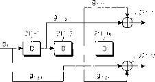
图4是示意性图解具有两个编码器和3个发送天线的STTC发送器的结构的方框图。参见图4,当两个信息数据比特d1和d2被输入到发送器时,输入的信息数据比特被施加到S/P转换器411。S/P转换器411并行转换信息数据比特d1和d2,并且向第一编码器421-1输出信息数据比特d1和向第二编码器421-2输出信息数据比特d2。如果假定第一编码器421-1具有约束长度K为4(约束长度K=4),则图2图解的第一编码器421-1的内部结构包括3个延迟(1+2D+D3)和3个模加法器,其中延迟和模加法器的数量等于比约束长度K=4小1的值。因此,在第一编码器421-1中,被施加到第一延迟器的未延迟的信息数据比特d1、通过将被第一延迟器延迟一次的一个比特乘以2而确定一个比特、被第三延迟器延迟三次的一个比特被提供给与第一发送天线ANT#1的第一调制器431连接的第一模加法器。以这种方式,第一编码器421-1的3个模加法器的输出被分别提供到第一调制器431-1、第二调制器431-1和第三调制器431-3。类似地,第二编码器421-2以与由第一编码器421-1使用0的相同的编码方法来编码从S/P转换器411输出的信息数据比特d2,然后,向第一调制器431-1、第二调制器431-1和第三调制器431-3提供它的输出。FIG. 4 is a block diagram schematically illustrating the structure of an STTC transmitter having two encoders and 3 transmission antennas. Referring to FIG. 4 , when two information data bits d1 and d2 are input to the transmitter, the input information data bits are applied to the S/P converter 411 . The S/P converter 411 converts the information data bits d1 and d2 in parallel, and outputs the information data bit d1 to the first encoder 421-1 and the information data bit d2 to the second encoder 421-2. If it is assumed that the first encoder 421-1 has a constraint length K of 4 (constraint length K=4), the internal structure of the first encoder 421-1 illustrated in FIG. 2 includes 3 delays (1+2D+D3 ) and 3 modulo adders, where the number of delays and modulo adders is equal to a
第一调制器431-1以预定的调制方案来调制从第一编码器421-1、第二编码器421-2输出的信号,并且向第一复用器441-1提供它的输出。在此假定被应用到发送器的调制方案是QPSK。因此,如果第一编码器421-1的输出信号是b1并且第二编码器421-2的输出信号是b2,则第一调制器431-1以QPSK调制方案来调制输出信号,开且输出b1+b2*j,其中
图5是示意地图解了对应于图1所示的发送器结构的接收器结构的方框图。参见图5,通过接收器的接收天线接收由发送器发送到空中的信号。在图5中假定提供了N个接收天线。所述N个接收天线每个处理从空中接收的信号。具体地说,通过第一接收天线ANT#1接收的信号被提供到第一去复用器(DEMUX)511-1,并且以相同的方式,通过第N个接收天线ANT#N接收的信号被提供给第N个去复用器511-N。第一到第N个去复用器511-1到511-N去复用从第一到第N个接收天线ANT#1到ANT#N接收的信号,并且将它们的输出提供到信道估计器513或度量计算器515。在此,第一到第N个去复用器511-1到511-N将它们的输入信号去复用为信息数据、训练序列或导频序列。换句话说,第一到第N个去复用器511-1到511-N去复用要与发送器的对应发送间隔匹配的所接收信号,如参照图3所述。即,如果所接收的信号对应于其中接收训练序列的间隔,则第一到第N个去复用器511-1到511-N向信道估计器513提供所接收的训练序列。如果所接收的信号对应于其中接收信息数据的间隔,则第一到第N个去复用器511-1到511-N向度量计算器515提供所接收的信息数据。如果所接收的信号对应于其中接收到导频序列的间隔,则第一到第N个去复用器511-1到511-N向信道估计器513提供所接收的导频序列。FIG. 5 is a block diagram schematically illustrating a receiver structure corresponding to the transmitter structure shown in FIG. 1 . Referring to FIG. 5, the signal sent into the air by the transmitter is received through the receiving antenna of the receiver. It is assumed in FIG. 5 that N reception antennas are provided. The N receiving antennas each process signals received from the air. Specifically, a signal received through the first receiving
信道估计器513使用从训练序列产生器514输出的信号来信道估计从第一到第N个去复用器511-1到511-N输出的信号,并且向推测部分517输出信道估计结果。在此,训练序列产生器514产生在发送器中产生的训练序列或导频序列,即与由参照图1所述的训练序列产生器151产生的训练序列或导频序列相同的训练序列或导频序列。因此,信道估计器513通过比较在训练序列接收间隔接收的第一到第N个去复用器511-1到511-N的输出信号与从训练序列产生器514输出的信号来执行初始的信道估计。在A.F.Naguib,V.Tarokh,N.Seshadri,and A.Calderbank,“A Space Time Coding Modem For HighData Rate Wireless Communications,”IEEE Journal on selected areas incommunications,pp.1459-1478,Vol,No.8.Oct.1998(A.F.Naguib、V.Tarokh、N.Seshadri,和A.Calderbank,“用于高数据率无线通信的时空编码调制解调器”,电气和电子工程师协会的通信选择区域期刊,第1459-1478页,第8册,1998年10月)中公开了一种使用训练序列来执行初始信道估计的方法。The
一种可能的序列产生器519产生可能被同时编码用于由发送器发送的信息数据比特的所有种类的序列,并且向第一到第P个编码器521-1到521-P提供所产生的序列。因为发送器通过P个信息比特发送信息数据,因此所述可能的序列产生器519产生包括P个比特的可能序列所产生的可能序列的P个比特被应用到第一到第P个编码器521-1到521-P,并且第一到第P个编码器521-1到521-P以参照图2所述的STTC编码方案来编码它们的输入比特,然后向第一到第M个调制器531-1到531-M提供编码的比特。第一到第M个调制器531-1到531-M每个以预定的调制方案来调制从第一到第P个编码器521-1到521-P输出的编码比特,并且向推测(hypothesis)部分517提供它们的输出。在第一到第M个调制器531-1到531-M中应用的调制方案被设置为BPSK、QPSK、QAM、PAM和PSK调制方案之中的任何一个。因为在图1的第一到第M个调制器141-1到141-M中应用的调制方案是2P元QAM,因此第一到第M个调制器531-1到531-M也以2P元QAM调制方案来调制它们的输入信号。One
推测部分517接收从第一到第M个调制器531-1到531-M输出的调制码元和来自信道估计器513的信道估计值输出
以这种方式,度量计算器515对于发送器可以发送的所有可能序列计算欧几里得距离,然后向最小距离选择器523提供所计算的欧几里得距离。最小距离选择器523从自度量计算器515输出的欧几里得距离选择具有最小距离的欧几里得距离,确定对应于所选择的欧几里得距离的信息比特来作为由发送器发送的信息比特,并且向并串(P/S)转换器525提供所确定的信息比特。虽然存在当最小距离选择器523确定对应于具有最小距离的欧几里得距离的信息比特时使用的几种可能的算法,但是在此假定使用Viterbi算法。在Vahid Tarokh,N.Seshadri,A.Calderbank,“Space Time Codes For High DataRate Wireless Communication:Performance Criterion And Code Construction,”IEEE Trans.on Info.Theory,pp.744-765,Vol.44,No.2,March 1998(VahidTarokh、N.Seshadri和A.Calderbank,“用于高数据率无线通信的时空代码:性能标准和代码构造”,电气和电子工程师协会信息理论会报,第744-765页,第44卷,第2册,1998年3月)中公开了使用Viterbi算法来提取具有最小距离的信息比特的处理,因此为了简单,不提供其详细的说明。In this way, the
因为最小距离选择器523对于从可能序列产生器519产生的所有序列确定对应于具有最小距离的欧几里得距离的信息比特,因此它最终输出P个信息比特

如上参照图1-5所述,使用STTC的发送器发送一个训练序列和导频序列来用于初始的信道估计和通信中的信道估计,并且在训练序列和导频序列的发送期间,除了训练序列和导频序列之外,不通过发送器的所有发送天线发送信息数据,因为在发送训练序列和导频序列期间,因此降低了发送器的数据率。例如,当发送器具有两个发送天线时,在发送训练序列和导频序列的间隔中通过全部两个发送天线而发送训练序列和导频序列。因此,在其中发送训练序列和导频序列的间隔中,不可能发送信息数据。由于不可能发送信息数据,因此降低了发送器的数据率,并且如果对于一个帧存在总共L个导频序列发送间隔和信息数据发送间隔,则整体的开销变为(LTP+TT)/(LTP+LTD+TT)。例如,假定其中发送信息数据的间隔TD具有比其中发送导频序列的间隔TP大3倍的长度,如果L被设置为较大的值,则发送器的开销是整体开销的25%。即,发送器的数据率的降低导致系统性能的下降。As described above with reference to Figures 1-5, the transmitter using STTC sends a training sequence and pilot sequence for initial channel estimation and channel estimation in communication, and during the transmission of the training sequence and pilot sequence, in addition to training Except for the training sequence and the pilot sequence, the information data is not transmitted through all the transmitting antennas of the transmitter, because during the transmission of the training sequence and the pilot sequence, the data rate of the transmitter is thus reduced. For example, when the transmitter has two transmission antennas, the training sequence and the pilot sequence are transmitted through both transmission antennas in the interval between transmitting the training sequence and the pilot sequence. Therefore, in the interval in which the training sequence and the pilot sequence are transmitted, it is impossible to transmit information data. Since it is impossible to send information data, the data rate of the transmitter is reduced, and if there are a total of L pilot sequence transmission intervals and information data transmission intervals for one frame, the overall overhead becomes (LTP +TT )/ (LTP +LTD +TT ). For example, assuming that the interval TD in which information data is transmitted has a length 3 times greater than the interval TP in which pilot sequences are transmitted, if L is set to a large value, the overhead of the transmitter is 25% of the overall overhead. That is, a decrease in the data rate of the transmitter results in a decrease in system performance.
发明内容Contents of the invention
因此,本发明的一个目的在于提供一种用于在使用STTC的移动通信系统中发送/接收导频序列的装置和方法。Accordingly, an object of the present invention is to provide an apparatus and method for transmitting/receiving a pilot sequence in a mobile communication system using STTC.
本发明的另一个目的在于提供一种用于在使用STTC的移动通信系统中最大化数据率的导频序列发送/接收装置和方法。Another object of the present invention is to provide a pilot sequence transmission/reception apparatus and method for maximizing a data rate in a mobile communication system using STTC.
为了实现上述和其他目的,本发明提供了一种用于在移动通信系统中发送用于信道估计的序列的装置,所述移动通信系统包括M个发送天线、用于接收P个信息比特流和使用时空格码(STTC)来编码所接收的信息比特流的P个编码器、用于以预定的调制方案调制从P个编码器输出的信息比特流并且输出调制码元流的M个调制器。所述装置包括:序列产生器,用于产生用于信道估计的序列;M个收缩器,用于对于从M个调制器输出的每个调制码元流收缩在预定的位置的至少一个调制码元;M个复用器,分别连接到M个发送天线,用于复用从M个收缩器输出的信号和在被收缩的调制码元中插入的序列。In order to achieve the above and other objects, the present invention provides an apparatus for transmitting a sequence for channel estimation in a mobile communication system, the mobile communication system comprising M transmitting antennas, for receiving P information bit streams and P encoders for encoding received information bit streams using space-time codes (STTC), M modulators for modulating the information bit streams output from the P encoders with a predetermined modulation scheme and outputting modulated symbol streams . The device includes: a sequence generator, used to generate a sequence for channel estimation; M puncturers, used to puncture at least one modulation code at a predetermined position for each modulation symbol stream output from M modulators element; M multiplexers, respectively connected to the M transmit antennas, for multiplexing the signals output from the M puncturers and the sequences inserted in the punctured modulation symbols.
为了实现上述和其他目的,本发明还提供了一种用于在移动通信系统中接收用于信道估计的序列的装置,所述移动通信系统通过N个接收天线接收由发送器通过M个发送天线发送的调制码元流。所述装置包括:N个去复用器,分别连接到N个接收天线,用于对于从N个接收天线输出的每个接收码元流,按照预定的收缩矩阵对所接收的信号去复用,来作为信道估计的序列;信道估计器,用于使用从N个去复用器输出的用于信道估计的序列来执行信道估计。In order to achieve the above and other objects, the present invention also provides a device for receiving a sequence used for channel estimation in a mobile communication system. The transmitted modulation symbol stream. The device includes: N demultiplexers, respectively connected to N receiving antennas, for demultiplexing received signals according to a predetermined contraction matrix for each received symbol stream output from the N receiving antennas , as a sequence for channel estimation; a channel estimator for performing channel estimation using the sequences for channel estimation output from the N demultiplexers.
为了实现上述和其他目的,本发明提供了一种用于在移动通信系统中发送用于信道估计的序列的方法,所述移动通信系统包括M个发送天线、用于接收P个信息比特流和使用时空格码(STTC)来编码所接收的信息比特流的P个编码器、用于以预定的调制方案调制从P个编码器输出的信息比特流并且输出调制码元流的M个调制器。所述方法包括步骤:产生用于信道估计的序列;对于从M个调制器输出的每个调制码元流,通过M个发送天线收缩在预定的位置的至少一个调制码元;以及复用收缩的信号和在被收缩的调制码元中插入的序列。In order to achieve the above and other objects, the present invention provides a method for transmitting a sequence for channel estimation in a mobile communication system, the mobile communication system includes M transmitting antennas, for receiving P information bit streams and P encoders for encoding received information bit streams using space-time codes (STTC), M modulators for modulating the information bit streams output from the P encoders with a predetermined modulation scheme and outputting modulated symbol streams . The method comprises the steps of: generating a sequence for channel estimation; for each modulation symbol stream output from M modulators, puncturing at least one modulation symbol at a predetermined position through M transmit antennas; and multiplexing the puncture The signal and the sequence inserted in the punctured modulation symbols.
为了实现上述和其他目的,本发明还提供了一种用于在移动通信系统中接收用于信道估计的序列的方法,所述移动通信系统通过N个接收天线接收由发送器通过M个发送天线发送的调制码元流。所述方法包括步骤:对于从N个接收天线输出的每个接收码元流,按照预定的收缩矩阵对所接收的信号去复用,来作为信道估计的序列;使用用于信道估计的序列来执行信道估计。In order to achieve the above and other objects, the present invention also provides a method for receiving a sequence used for channel estimation in a mobile communication system, the mobile communication system receives through N receiving antennas the sequence received by the transmitter through M transmitting antennas The transmitted modulation symbol stream. The method includes the steps of: for each received symbol stream output from N receiving antennas, demultiplexing the received signal according to a predetermined contraction matrix as a sequence for channel estimation; using the sequence for channel estimation to Perform channel estimation.
附图说明Description of drawings
通过参照附图下面详细说明,本发明的上述和其他目的、特点和优点将会变得更加清楚,其中:The above and other objects, features and advantages of the present invention will become more apparent by the following detailed description with reference to the accompanying drawings, in which:
图1是图解使用STTC的发送器的传统结构的方框图;FIG. 1 is a block diagram illustrating a conventional structure of a transmitter using STTC;
图2是图解图1所示的第一到第P个编码器121-1到121-P的详细结构的方框图;FIG. 2 is a block diagram illustrating a detailed structure of first to P-th encoders 121-1 to 121-P shown in FIG. 1;
图3示意性图解由图1所示的发送器发送的帧格式;Fig. 3 schematically illustrates the frame format sent by the transmitter shown in Fig. 1;
图4是示意性图解包括2个编码器和3个发送天线的STTC发送器的结构的方框图;4 is a block diagram schematically illustrating the structure of an STTC transmitter including 2 encoders and 3 transmitting antennas;
图5是示意性图解与图1所示的发送器结构相对应的接收器结构的方框图;FIG. 5 is a block diagram schematically illustrating a receiver structure corresponding to the transmitter structure shown in FIG. 1;
图6是图解按照本发明的一个实施例的使用时空格码(STTC)的发送器结构的方框图;6 is a block diagram illustrating a transmitter structure using a space-time code (STTC) according to one embodiment of the present invention;
图7示意性图解由图6的发送器发送的帧格式;Fig. 7 schematically illustrates the frame format sent by the transmitter of Fig. 6;
图8是示意性图解与图6的发送器结构对应的接收器结构的方框图;FIG. 8 is a block diagram schematically illustrating a receiver structure corresponding to the transmitter structure of FIG. 6;
图9是图解本发明的模拟结果的图。FIG. 9 is a graph illustrating simulation results of the present invention.
具体实施方式Detailed ways
以下,参照附图来详细说明本发明的几个优选实施例。在附图中,相同或类似的元件由相同的附图标号表示,即使它们在不同的附图中被描述。在下面的说明中,为了简明,已经省略了公知的功能和在此并入的配置的详细说明。Hereinafter, several preferred embodiments of the present invention will be described in detail with reference to the accompanying drawings. In the drawings, the same or similar elements are denoted by the same reference numerals even if they are depicted in different drawings. In the following description, a detailed description of well-known functions and configurations incorporated herein has been omitted for conciseness.
图6是图解按照本发明的一个实施例的使用时空格码(STTC)的发送器结构的方框图。参见图6,当P个信息数据比特d1、d2、d3、...、dP被输入到发送器时,输入的信息数据比特d1、d2、d3、...、dP被提供到串并(S/P)转换器611。在此,下标P表示在单位发送时间中要由发送器发送的信息数据比特的数量,所述单位发送时间可以变为码元单位,S/P转换器611并行转换信息数据比特d1、d2、d3、...、dP,并且向第一到第P个编码器621-1到621-P提供它的输出。即,S/P转换器611向第一编码器621-1提供并行转换的信息数据比特d1,并且以这种方式,向第P个编码器621-P提供并行转换的信息数据比特dP。第一编码器621-1随后以预定的编码方案编码信息数据比特d1,然后向第一到第M调制器631-1到631-M提供它的输出。在此,下标M表示在发送器中包括的发送天线的数量,并且所述编码方案是STTC编码方案。以这种方式,第P个编码器621-P以STTC编码方案编码信息数据比特dP,然后向第一到第M调制器631-1到631-M提供它的输出。第一到第P个编码器621-1到621-P的内部结构与图2所示的结构相同,因此为了简单省略对其的详细说明。FIG. 6 is a block diagram illustrating the structure of a transmitter using a space-time code (STTC) according to an embodiment of the present invention. Referring to FIG. 6, when P information data bits d1 , d2 , d3 , ..., dP are input to the transmitter, the input information data bits d1 , d2 , d3 , ..., dP is provided to a serial-to-parallel (S/P)
第一到第M调制器631-1到631-M每个以预定的调制方案来调制从第一到第P个编码器621-1到621-P输出的调制信号。第一到第M调制器631-1到631-M彼此在操作上类似,除了被施加到其上的信号。因此,在此仅仅说明第一调制器631-1。第一调制器631-1将从第一到第P个编码器621-1到621-P输出的信号相加,将相加的结果乘以应用到与第一调制器631-1连接的发送天线、即第一发送天线ANT#1的增益,以预定的调制方案调制相乘的结果,并且向第一收缩器(puncturer)641-1提供调制结果。在此,所述调制方案包括BPSK(二进制相移键控)、QPSK(四相移键控)、QAM(正交调幅)、PAM(脉冲幅度调制)和PSK(相移键控)。在图6中假定:因为编码器的数量是P,因此将2P元QAM用作调制方案。The first to Mth modulators 631-1 to 631-M each modulate modulation signals output from the first to Pth encoders 621-1 to 621-P with a predetermined modulation scheme. The first to Mth modulators 631-1 to 631-M are similar in operation to each other except for signals applied thereto. Therefore, only the first modulator 631-1 is described here. The first modulator 631-1 adds the signals output from the first to Pth encoders 621-1 to 621-P, and multiplies the added result by The antenna, that is, the gain of the first transmission
第一到第M调制器631-1到631-M分别向第一到第M个收缩器641-1到641-M提供它们的调制码元S1到SM。第一到第M个收缩器641-1到641-M按照预定的收缩矩阵收缩(puncture)从第一到第M调制器631-1到631-M接收的调制码元S1到SM,然后分别向第一到第M复用器651-1到651-M提供它们的输出。在本发明中,第一到第M个收缩器641-1到641-M按照发送天线分别定期收缩从第一到第M调制器631-1到631-M输出的调制码元S1到SM。The first to Mth modulators 631-1 to 631-M provide their modulation symbolsS1 to SM to the first to Mth puncturers 641-1 to 641-M, respectively. The first to M punctures 641-1 to 641-M puncture (puncture) the modulation symbols S1 to SM received from the first to M modulators 631-1 to 631-M according to a predetermined puncture matrix, Their outputs are then provided to the first to Mth multiplexers 651-1 to 651-M, respectively. In the present invention, the first to Mth puncturers 641-1 to 641-M periodically puncture the modulation symbolsS1 to S output from the first to Mth modulators 631-1 to 631-M according to the transmitting antennaM.
现在详细说明其中第一到第M个收缩器641-1到641-M按照收缩矩阵收缩从第一到第M调制器631-1到631-M输出的调制码元S1到SM的程序。A procedure in which the first to Mth puncturers 641-1 to 641-M shrink the modulation symbolsS1 to S M outputted from the first to Mth modulators 631-1 to 631-M according to the puncture matrix will now be described in detail .
例如,假定在发送器中包括的发送天线的数量是2,当在单位发送间隔中通过2个发送天线发送4个码元时,适用于下面的方程(1)的收缩矩阵。For example, assuming that the number of transmission antennas included in the transmitter is 2, when 4 symbols are transmitted through 2 transmission antennas in a unit transmission interval, the contraction matrix of Equation (1) below applies.
方程(1)Equation (1)
在方程(1)中,P1表示收缩矩阵。在收缩矩阵P1中,列表示发送间隔,即码元间隔,行表示发送天线。在收缩矩阵P1中,元素“1”指示一个输入码元被收缩,以便对于对应的间隔不发送码元。即,在收缩矩阵P1中,对于第一列或第一码元间隔,从连接到第一发送天线的第一调制器输出的信号和从连接到第二发送天线的第二调制器输出的信号被通过而不进行收缩。但是,在收缩矩阵P1中,对于第二列或第二码元间隔,从连接到第一发送天线的第一调制器输出的信号被通过而不进行收缩,而从连接到第二发送天线的第二调制器输出的信号被收缩。因此,对于应用了收缩矩阵P1的情况的编码率比对于未应用了收缩矩阵P1的情况的编码率大4/3倍。In Equation (1), P1 represents the contraction matrix. In the contraction matrixP1 , the columns represent the transmission intervals, that is, the symbol intervals, and the rows represent the transmission antennas. In the punctured matrixP1 , an element "1" indicates that an input symbol is punctured so that no symbols are transmitted for the corresponding interval. That is, in the punctured matrixP1 , for the first column or first symbol interval, the signal output from the first modulator connected to the first transmit antenna and the signal output from the second modulator connected to the second transmit antenna The signal is passed without contraction. However, in the punctured matrixP1 , for the second column or symbol interval, the signal output from the first modulator connected to the first transmit antenna is passed without puncture, while the signal output from the first modulator connected to the second transmit antenna The output signal of the second modulator is contracted. Therefore, the encoding rate for the case where the puncture matrixP1 is applied is 4/3 times larger than the encoding rate for the case where the puncture matrixP1 is not applied.
作为另一个示例,假定在发送器中包括的发送天线的数量是2,当在单位发送间隔中通过2个发送天线发送6个码元时,适用于下面的方程(2)的收缩矩阵。As another example, assuming that the number of transmission antennas included in the transmitter is 2, when 6 symbols are transmitted through 2 transmission antennas in a unit transmission interval, the contraction matrix of Equation (2) below applies.
在方程(2)中,P2表示收缩矩阵。在收缩矩阵P2中,列表示发送间隔,即码元间隔,行表示发送天线。在收缩矩阵P2中,元素“1”指示一个输入码元被通过而不进行收缩,而元素“0”表示一个输入码元被收缩,因此在对应的间隔内不发送任何码元。In equation (2),P2 represents the contraction matrix. In the contraction matrixP2 , the columns represent the transmission intervals, that is, the symbol intervals, and the rows represent the transmission antennas. In the puncture matrixP2 , an element "1" indicates that an input symbol is passed without puncturing, while an element "0" indicates that an input symbol is punctured, so no symbols are transmitted during the corresponding interval.
以这种方式,第一到第M个收缩器641-1到641-M通过它们的输入码元而不收缩或者按照收缩矩阵收缩它们的输入码元,并且向第一到第M复用器651-1到651-M提供它们的输出。第一到第M复用器651-1到651-M复用从第一到第M个收缩器641-1到641-M输出的信号,然后将它们的输出提供到第一到第M个发送天线ANT#1到ANT#M。以下说明第一到第M复用器651-1到651-M的操作。In this way, the first to Mth puncturers 641-1 to 641-M pass their input symbols without puncturing or puncture their input symbols according to the puncture matrix, and send to the first to Mth multiplexers 651-1 through 651-M provide their outputs. The first to Mth multiplexers 651-1 to 651-M multiplex the signals output from the first to Mth shrinkers 641-1 to 641-M, and then supply their outputs to the first to Mth Transmitting
因为第一到第M复用器651-1到651-M彼此在操作上类似,为了简单,仅仅说明第一复用器651-1。第一复用器651-1按照收缩矩阵复用从第一收缩器641-1输出的信号。即,如果收缩矩阵的对应元素是“1”,则第一复用器651-1通过第一发送天线ANT#1发送从第一收缩器641输出的未扰动信号,相反,如果收缩矩阵的对应元素是“0”,则因为没有信号从第一收缩器641-1被输出,因此第一收缩器641-1复用从训练序列产生器661输出的信号,即训练序列或导频序列,然后通过第一发送天线ANT#1发送被复用的信号,以这种方式,第M个复用器651-M按照收缩矩阵复用从第M个收缩器641-M输出的信号和从训练序列产生器661输出的信号,然后通过第M个发送天线ANT#M发送它的输出。在此,应用收缩矩阵的发送间隔是其中发送导频序列的间隔,训练序列以现有的方式被发送。Since the first to Mth multiplexers 651-1 to 651-M are similar in operation to each other, for simplicity, only the first multiplexer 651-1 is explained. The first multiplexer 651-1 multiplexes the signal output from the first puncturer 641-1 according to the puncture matrix. That is, if the corresponding element of the puncture matrix is "1", the first multiplexer 651-1 transmits the unperturbed signal output from the
结果,通过第一到第M个发送天线ANT#1到ANT#M发送的码元定期包括导频序列,并且通过防止仅仅一个发送导频序列的发送天线发送信息数据、而不是防止所有的第一到第M个发送天线ANT#1到ANT#M发送信息数据来提高数据率,以便发送导频序列。在图6中,第一到第M个收缩器641-1到641-M按照收缩矩阵收缩对应的码元。或者,第一到第M复用器651-1到651-M可以在发送之前按照收缩矩阵复用对应的信号,而不是使第一到第M个收缩器641-1到641-M能收缩对应的码元。在这种情况下,第一到第M个收缩器641-1到641-M可以被排除。As a result, symbols transmitted through the first to Mth transmission
如上参照图6所述,本发明定期地通过发送器的一个发送天线而不是所有的发送天线来发送导频序列,有助于数据率的提高。As described above with reference to FIG. 6, the present invention periodically transmits pilot sequences through one transmit antenna of the transmitter instead of all transmit antennas, which contributes to the improvement of the data rate.
图7示意性图解由图6的发送器发送的帧格式。在图6中图解的发送器中包括的发送天线的数量是2的假定下说明图7。参见图7,通过第一发送天线ANT#1和第二发送天线ANT#2发送的每个帧格式包括训练序列发送间隔(Training_Sequence)811、信息数据发送间隔(D)813、导频序列发送间隔(P)815。训练序列发送间隔811是其中发送用于在发送器和接收器之间的初始信道估计的训练序列的时间间隔。信息数据发送间隔813是其中发送实际信息数据的时间间隔,导频序列发送间隔815是其中发送用于在实际信息数据的发送/接收期间的信道估计的导频序列。在此,其中发送训练序列的时间间隔被定义为“TT”,其中发送信息数据的时间间隔被定义为“TD”,其中发送导频序列的时间间隔被定义为“TP”。在现有技术中,如参照图3所述,发送器(1)仅仅发送对于时间间隔TT的训练序列,(2)发送对于时间间隔TD的信息数据,(3)仅仅发送对于时间间隔TP的导频序列。当在传统的方法中发送导频序列时,对于导频序列的一个发送间隔不发送信息数据,使得降低了数据率。但是,本发明在按照图7所示的帧格式发送信息数据的同时定期地按照收缩矩阵收缩信息数据,并且在发送之前在收缩信息数据的部分中插入一个导频序列。因此有可能即使当发送导频序列时发送信息数据,因此有助于提高数据率。FIG. 7 schematically illustrates a frame format transmitted by the transmitter of FIG. 6 . FIG. 7 is explained on the assumption that the number of transmission antennas included in the transmitter illustrated in FIG. 6 is two. Referring to FIG. 7, each frame format transmitted by the first transmitting
图8是示意性图解与图6的发送器结构对应的接收器结构的方框图。参见图8,通过发送器发送到空中的信号通过接收器的接收天线接收。在图8中假定提供了N个接收天线。所述N个接收天线每个处理从空中接收的信号。具体地说,通过第一接收天线ANT#1接收的信号被提供到第一去复用器(DEMUX)911-1,并且以这种方式,通过第N个接收天线ANT#N接收的信号被提供给第N个去复用器911-N。第一到第N个去复用器911-1到911-N去复用从第一到第N个接收天线ANT#1到ANT#N接收的信号,并且将它们的输出提供到信道估计器913或度量计算器915。在此,第一到第N个去复用器911-1到911-N将它们的输入信号去复用为信息数据、训练序列或导频序列。换句话说,第一到第N个去复用器911-1到911-N去复用要与发送器的对应发送间隔匹配的所接收信号,如参照图7所述。FIG. 8 is a block diagram schematically illustrating a receiver structure corresponding to the transmitter structure of FIG. 6 . Referring to FIG. 8, a signal sent into the air by a transmitter is received by a receiving antenna of a receiver. It is assumed in FIG. 8 that N receiving antennas are provided. The N receiving antennas each process signals received from the air. Specifically, the signal received through the first receiving
即,如果所接收的信号对应于其中接收训练序列的间隔,则第一到第N个去复用器911-1到911-N向信道估计器913提供所接收的训练序列。如果所接收的信号对应于其中接收信息数据的间隔,则第一到第N个去复用器911-1到911-N向度量计算器915提供所接收的信息数据。如果所接收的信号对应于其中接收到导频序列的间隔,则第一到第N个去复用器911-1到911-N向信道估计器513提供所接收的导频序列。在本发明中,因为发送器通过应用收缩矩阵而发送信息数据、训练序列或导频序列,因此第一到第N个去复用器911-1到911-N按照收缩矩阵将所接收的信号去复用为信息数据、训练序列或导频序列。即,如果收缩矩阵的一个元素是“1”,则第一到第N个去复用器911-1到911-N向度量计算器915提供所接收的信号,如果收缩矩阵的一个元素是“0”,则第一到第N个去复用器911-1到911-N向信道估计器913提供所接收的信号。That is, if the received signal corresponds to an interval in which a training sequence is received, the first to Nth demultiplexers 911 - 1 to 911 -N provide the received training sequence to the channel estimator 913 . If the received signal corresponds to an interval in which information data is received, the first to Nth demultiplexers 911 - 1 to 911 -N provide the metric calculator 915 with the received information data. If the received signal corresponds to the interval in which the pilot sequence is received, the first to Nth demultiplexers 911-1 to 911-N provide the received pilot sequence to the
信道估计器913利用从训练序列产生器914输出的信号来信道估计从第一到第N个去复用器911-1到911-N输出的信号,并且向推测部分917输出信道估计的结果。在此,训练序列产生器914产生在发送器中产生的训练序列或导频序列,即与由参照图6所述的训练序列产生器661产生的训练序列或导频序列相同的训练序列或导频序列。因此,信道估计器913通过比较在收缩矩阵的元素是“1”的间隔接收的第一到第N个去复用器911-1到911-N的输出信号与从训练序列产生器914输出的信号来执行初始的信道估计。在Vahid Tarokh,N.Seshadri,A.Calderbank,“Space Time Codes For High DataRate Wireless Communication:Performance Criterion And Code Construction,”IEEE Trans.on Info.Theory,pp.744-765,Vol.44,No.2,March 1998(VahidTarokh、N.Seshadri和A.Calderbank,“用于高数据率无线通信的时空代码:性能标准和代码构造”,电气和电子工程师协会信息理论会报,第744-765页,第44卷,第2册,1998年3月)中公开了一种使用训练序列或导频序列来执行信道估计的处理,因此省略其详细说明。The channel estimator 913 uses the signal output from the training sequence generator 914 to channel estimate the signals output from the first to Nth demultiplexers 911 - 1 to 911 -N, and outputs the result of the channel estimation to the estimation part 917 . Here, the training sequence generator 914 generates the training sequence or pilot sequence generated in the transmitter, that is, the same training sequence or pilot sequence as the training sequence or pilot sequence generated by the training sequence generator 661 described with reference to FIG. 6 . frequency sequence. Therefore, the channel estimator 913 compares the output signals of the first to Nth demultiplexers 911-1 to 911-N received at intervals in which the elements of the puncture matrix are "1" with the output signals from the training sequence generator 914. signal to perform initial channel estimation. In Vahid Tarokh, N. Seshadri, A. Calderbank, "Space Time Codes For High DataRate Wireless Communication: Performance Criterion And Code Construction," IEEE Trans. on Info. Theory, pp.744-765, Vol.44, No.2 , March 1998 (VahidTarokh, N. Seshadri, and A. Calderbank, "Space-time codes for high-data-rate wireless communications: performance criteria and code construction", Transactions of the Institute of Electrical and Electronics Engineers Information Theory, pp. 744-765, pp. 44, Vol. 2, March 1998) discloses a process of performing channel estimation using a training sequence or a pilot sequence, and thus a detailed description thereof is omitted.
一种可能的序列产生器919产生可能被同时编码用于由发送器发送的信息数据比特的所有种类的序列,并且向第一到第P个编码器921-1到921-P提供所产生的序列。因为发送器通过P个信息比特发送信息数据,因此所述可能的序列产生器919产生包括P个比特的可能序列
第一到第M个调制器931-1到931-M以2P元QAM调制方案调制从第一到第P个编码器921-1到921-P输出的信号,然后向第一到第M个收缩器941-1到941-M提供它们的输出。第一到第M个收缩器941-1到941-M按照与图6所示的第一到第M个收缩器641-1到641-M中应用的收缩矩阵相同的收缩矩阵来收缩从第一到第M个调制器931-1到931-M输出的调制码元,然后向推测部分917提供它们的输出。推测部分917接收从第一到第M个收缩器9411到941-M输出的信号和从信道估计器913输出的信道估计结果,并且当由从第一到第M个收缩器941-1到941-M输出的信号构成的序列通过对应于信道估计结果的信道的时候产生推测信道输出,并且向度量计算器915提供所产生的推测信道输出。当第一到第M个收缩器941-1到941-M按照收缩矩阵执行收缩操作时,不存在从一个特定的收缩器输出的信号。但是,在本发明中,因为第一到第M个收缩器941-1到941-M按照收缩矩阵执行收缩操作并且向被收缩的间隔查获如一个导频序列,因此必须考虑插入导频序列的效果。The first to Mth modulators 931-1 to 931-M modulate the signals output from the first to Pth encoders 921-1 to 921-P with a 2P -ary QAM modulation scheme, and then transmit the signals to the first to Mth Shrinkers 941-1 through 941-M provide their outputs. The first to Mth shrinkers 941-1 to 941-M shrink the first to Mth shrinkers 641-1 to 941-M according to the same shrinkage matrix as that applied in the first to Mth shrinkers 641-1 to 641-M shown in FIG. Modulation symbols output by the first to Mth modulators 931 - 1 to 931 -M are then supplied to the guessing section 917 with their outputs. The estimation part 917 receives the signals output from the first to Mth puncturers 9411 to 941-M and the channel estimation result output from the channel estimator 913, and when the signal is output by the first to Mth puncturers 941-1 to 941 - When the sequence of signals output by M passes through the channel corresponding to the channel estimation result, a presumed channel output is generated, and the generated presumed channel output is provided to the metric calculator 915 . When the first to Mth shrinkers 941-1 to 941-M perform the shrinking operation according to the shrinking matrix, there is no signal output from one specific shrinker. However, in the present invention, since the first to Mth puncturers 941-1 to 941-M perform the puncture operation according to the puncture matrix and acquire such a pilot sequence to the punctured interval, it is necessary to consider the problem of inserting the pilot sequence. Effect.
在从所接收的信号减去一个值后,度量计算器915必须计算一个度量,所述值是通过将导频序列乘以发送导频序列的信道的特征而被确定的,所述接收信号即从第一到第N个去复用器911-1到911-N输出的信号。因为导频序列对于发送端和接收端事先是知道的,因此在解码期间不存在由于导频序列而导致的解码增益的降低。度量计算器915接收从推测部分917提供的推测信道输出和从第一到第N个去复用器911-1到911-N输出的信号,并且计算在所述推测信道输出和第一到第N个去复用器911-1到911-N的输出信号之间的距离。度量计算器915当计算所述距离时使用欧几里得(Euclidean)距离。The metric calculator 915 must calculate a metric determined by multiplying the pilot sequence by the characteristics of the channel on which the pilot sequence was transmitted, after subtracting a value from the received signal, i.e. Signals output from the first to Nth demultiplexers 911-1 to 911-N. Since the pilot sequence is known in advance for the transmitting end and the receiving end, there is no reduction in decoding gain due to the pilot sequence during decoding. The metric calculator 915 receives the presumed channel output supplied from the presuming section 917 and signals output from the first to Nth demultiplexers 911-1 to 911-N, and calculates The distance between the output signals of the N demultiplexers 911-1 to 911-N. The metric calculator 915 uses Euclidean distance when calculating the distance.
以这种方式,度量计算器915对于发送器可以发送的所有可能序列计算欧几里得距离,然后向最小距离选择器923提供所计算的欧几里得距离。最小距离选择器923从自度量计算器915输出的欧几里得距离选择具有最小距离的欧几里得距离,确定对应于所选择的欧几里得距离的信息比特来作为由发送器发送的信息比特,并且向并串(P/S)转换器925提供所确定的信息比特。虽然存在当最小距离选择器923确定对应于具有最小距离的欧几里得距离的信息比特时使用的几种可能的算法,但是在此假定使用Viterbi算法。在Vahid Tarokh,N.Seshadri,A.Calderbank,“Space Time Codes For High DataRate Wireless Communication:Performance Criterion And Code Construction,”IEEE Trans.on Info.Theory,pp.744-765,Vol.44,No.2,March 1998(VahidTarokh、N.Seshadri和A.Calderbank,“用于高数据率无线通信的时空代码:性能标准和代码构造”,电气和电子工程师协会信息理论会报,第744-765页,第44卷,第2册,1998年3月)中公开了使用Viterbi算法来提取具有最小距离的信息比特的处理,因此为了简单,不提供其详细的说明。In this way, the metric calculator 915 calculates Euclidean distances for all possible sequences that the sender can transmit, and then provides the calculated Euclidean distances to the minimum distance selector 923 . The minimum distance selector 923 selects the Euclidean distance having the minimum distance from the Euclidean distances output from the metric calculator 915, and determines information bits corresponding to the selected Euclidean distance as the information bits transmitted by the transmitter. information bits, and provide the determined information bits to a parallel-to-serial (P/S) converter 925 . Although there are several possible algorithms used when the minimum distance selector 923 determines the information bits corresponding to the Euclidean distance having the minimum distance, it is assumed here that the Viterbi algorithm is used. In Vahid Tarokh, N. Seshadri, A. Calderbank, "Space Time Codes For High DataRate Wireless Communication: Performance Criterion And Code Construction," IEEE Trans. on Info. Theory, pp.744-765, Vol.44, No.2 , March 1998 (VahidTarokh, N. Seshadri, and A. Calderbank, "Space-time codes for high-data-rate wireless communications: performance criteria and code construction", Transactions of the Institute of Electrical and Electronics Engineers Information Theory, pp. 744-765, pp. 44, No. 2, March 1998) discloses the process of extracting the information bit with the minimum distance using the Viterbi algorithm, and therefore its detailed description is not provided for brevity.
因为最小距离选择器923对于从可能序列产生器919产生的所有序列确定对应于具有最小距离的欧几里得距离的信息比特,因此它最终输出P个信息比特
现在参照上述的发送器结构和接收器结构来说明本发明的操作。The operation of the present invention will now be described with reference to the transmitter and receiver structures described above.
首先,假定发送器具有2个发送天线,接收器具有1个接收天线。在接收由发送器向空中发送的信号来作为由下面的方程所给出的信号:First, assume that the transmitter has 2 transmit antennas and the receiver has 1 receive antenna. The signal sent by the transmitter into the air is received as a signal given by the following equation:
方程(3)Equation (3)
ri=h1s1,i+h2s2,i+niri =h1 s1,i +h2 s2,i +ni
在方程(3)中,ri表示在第i时间点所接收的信号,sji表示在第i时间点通过第j个发送天线发送的信号,ni表示在第i时间点的噪音分量,hj表示发送信号通过第j个发送天线经历的信道特征。In equation (3), ri represents the signal received at the i-th time point, sji represents the signal transmitted by the j-th transmitting antenna at the i-th time point, and ni represents the noise component at the i-th time point, hj represents the channel characteristics experienced by the transmitted signal through the jth transmit antenna.
例如,如果假定发送器使用BPSK作为它的调制方案并且STTC编码的约束长度是K(约束长度=K),则在对应于发送器的接收器接收的信号s1,i和s2,i被表示为信息数据比特dt-K、...、dt的线性组合。因此接收器通过考虑到信息数据比特dt-K、...、dt的所有可能组合而产生所接收的信号s1,i和s2,i的所有可能值。这些值是参照图8所述的可能序列产生器919产生的。另外,必须使用信道特征h1和h2来产生推测接收信号,并且通过将从实际接收的信号减去推测接收信号而确定的值被计算为度量。为了以这种方式来计算度量,必须确定信道特征h1和h2。为此,发送器发送训练序列,以便接收器可以检测信道特征h1和h2。For example, if it is assumed that the transmitter uses BPSK as its modulation scheme and the constraint length of the STTC code is K (constraint length = K), then the signals s1,i ands2,i received at the receiver corresponding to the transmitter are Expressed as a linear combination of information data bits dtK , . . . , dt . The receiver thus generates all possible values of the received signals s1,i and s2,i by taking into account all possible combinations of the information data bits dtK , ..., dt . These values are generated by the possible sequence generator 919 described with reference to FIG. 8 . In addition, it is necessary to generate the presumed received signal using the channel characteristicsh1 andh2 , and a value determined by subtracting the presumed received signal from the actually received signal is calculated as the metric. In order to calculate the metric in this way, the channel characteristicshi andh2 have to be determined. To this end, the transmitter sends training sequences so that the receiver can detect the channel characteristics h1 and h2 .
一般,训练序列在被发送之前被插入到帧的最前部分,因此启动在发送器和接收器之间的初始信道估计。但是,当信道环境经历频率变化并且其程度为在一个帧内改变信道特征时,提高帧差错率(FER)。因此,发送器在发送前在帧中插入一个导频序列以降低帧差错率。但是,当发送导频序列时,不发送信息数据,因此降低了数据率。Typically, a training sequence is inserted into the very first part of a frame before being transmitted, thus enabling initial channel estimation between the transmitter and receiver. However, when the channel environment undergoes frequency changes to such an extent that channel characteristics are changed within one frame, the frame error rate (FER) increases. Therefore, the transmitter inserts a pilot sequence in the frame before sending to reduce the frame error rate. However, when the pilot sequence is transmitted, no information data is transmitted, thus reducing the data rate.
例如,如在背景技术部分中所述,如果对于一个帧存在总共L个导频序列发送间隔和信息数据发送间隔,则整体的开销变为(LTP+TT)/(LTP+LTD+TT)。例如,假定其中发送信息数据的间隔TD具有比其中发送导频序列的间隔TP大3倍的长度,如果L被设置为较大的值,则发送器的开销是整体开销的25%。不利的是,发送器的数据率的降低导致系统性能的下降。但是,本发明定期地收缩信息数据的发送间隔和在被收缩的发送间隔中发送导频序列而不是独立地限定导频序列的发送间隔。结果,本发明可以发送导频序列而不降数据率。因此保持了系统的数据率。即,现有的使用STTC的发送器可以发送一个帧的LTD比特的信息数据,而本发明可以发送一个帧的LTP+LTD比特的信息数据。另外,有可能通过定期设置数据发送间隔而保持分集增益,所述数据发送间隔对于独立的天线经历收缩以插入导频序列。For example, as described in the background section, if there are a total of L pilot sequence transmission intervals and information data transmission intervals for one frame, the overall overhead becomes (LTP +TT )/(LTP +LTD +TT ). For example, assuming that the interval TD in which information data is transmitted has a length 3 times greater than the interval TP in which pilot sequences are transmitted, if L is set to a large value, the overhead of the transmitter is 25% of the overall overhead. Disadvantageously, a reduction in the data rate of the transmitter leads to a reduction in system performance. However, the present invention periodically shrinks the transmission interval of the information data and transmits the pilot sequence in the shortened transmission interval instead of independently defining the transmission interval of the pilot sequence. As a result, the present invention can transmit pilot sequences without reducing the data rate. The data rate of the system is thus maintained. That is, an existing transmitter using STTC can transmit information data of LTD bits for one frame, but the present invention can transmit information data of LTP +LTD bits for one frame. In addition, it is possible to maintain diversity gain by regularly setting data transmission intervals that undergo shrinkage for individual antennas to insert pilot sequences.
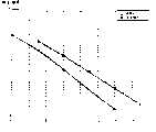
图9是图解本发明的模拟结果的图。在图9中假定在发送器中包括的发送天线的数量是2,被应用用于STTC编码的约束长度K是5(K=5),BPSK被应用为调制方案,一个帧包括20个码元并且具有15个信息数据码元间隔和5个导频序列码元间隔,在接收器中包括的接收天线的数量是1。另外,假定通过2个发送天线发送的信号经历独立的瑞利衰落信道,并且信道估计性能是100%。FIG. 9 is a graph illustrating simulation results of the present invention. Assuming in FIG. 9 that the number of transmit antennas included in the transmitter is 2, the constraint length K applied for STTC encoding is 5 (K=5), BPSK is applied as the modulation scheme, and one frame includes 20 symbols And with 15 information data symbol intervals and 5 pilot sequence symbol intervals, the number of reception antennas included in the receiver is one. In addition, it is assumed that signals transmitted through 2 transmission antennas experience independent Rayleigh fading channels, and channel estimation performance is 100%.
如图9所示,对于帧差错率0.1,本发明示出了与在导频序列发送期间不发送信息接收的一般STTC发送器相比较大约2dB的性能降低。本发明虽然受到帧差错率上的轻微性能降级的影响,但是有助于数据率上的性能增进。即,在一般的STTC发送器中,所有的发送天线在导频序列发送期间不能发送信息数据,因此接收器对于一个帧接收15个信息数据码元。但是,按照本发明的的STTC发送器即使在导频序列发送期间也可以发送信息数据,因此接收器可以对于一个帧接收20个信息数据码元。比较发送器,所提出的STTC发送器具有比现有的STTC发送器的数据率高4/3倍的数据率。As shown in FIG. 9, for a frame error rate of 0.1, the present invention shows about 2 dB performance degradation compared to a general STTC transmitter that does not transmit information reception during pilot sequence transmission. The present invention contributes to a performance increase in data rate, although it suffers from a slight performance degradation in frame error rate. That is, in a general STTC transmitter, all transmission antennas cannot transmit information data during pilot sequence transmission, so the receiver receives 15 information data symbols for one frame. However, the STTC transmitter according to the present invention can transmit information data even during pilot sequence transmission, so the receiver can receive 20 information data symbols for one frame. Comparing the transmitters, the proposed STTC transmitter has a
在使用STTC的移动通信系统中,本发明定期地收缩对于单独的发送天线的信息数据码元,并且对于一个被收缩的数据码元的发送间隔发送一个导频序列,因此防止了由于发送导频序列而导致的数据损耗。因此,在使用STTC的移动通信系统中,即使在发送导频序列期间也发送信息数据,因此提高了数据率和改进了系统性能。In a mobile communication system using STTC, the present invention periodically punctures information data symbols for individual transmit antennas, and transmits a pilot sequence for a transmission interval of a punctured data symbol, thus preventing Data loss due to sequence. Therefore, in a mobile communication system using STTC, information data is transmitted even during transmission of a pilot sequence, thereby increasing a data rate and improving system performance.
虽然已经参照本发明的实施例具体示出和说明了本发明,本领域的技术人员会明白,在不脱离所附的权利要求所限定的本发明的精神和范围的情况下,可以进行形式和细节上的各种改变。While the invention has been particularly shown and described with reference to the embodiments of the invention, it will be apparent to those skilled in the art that changes may be made in form and without departing from the spirit and scope of the invention as defined in the appended claims. Various changes in details.
Claims (20)
Translated fromChineseApplications Claiming Priority (3)
| Application Number | Priority Date | Filing Date | Title |
|---|---|---|---|
| KR10-2003-0004582AKR100526511B1 (en) | 2003-01-23 | 2003-01-23 | Apparatus for transmitting/receiving pilot sequence in mobile communication system using space-time trellis code and method thereof |
| KR4582/2003 | 2003-01-23 | ||
| KR4582/03 | 2003-01-23 |
Publications (2)
| Publication Number | Publication Date |
|---|---|
| CN1518238A CN1518238A (en) | 2004-08-04 |
| CN1272917Ctrue CN1272917C (en) | 2006-08-30 |
Family
ID=32588996
Family Applications (1)
| Application Number | Title | Priority Date | Filing Date |
|---|---|---|---|
| CNB2003101203166AExpired - Fee RelatedCN1272917C (en) | 2003-01-23 | 2003-12-05 | Device and method for transmitting/receiving pilot sequence in mobile communication using STTC |
Country Status (6)
| Country | Link |
|---|---|
| US (2) | US7480339B2 (en) |
| EP (1) | EP1441461B1 (en) |
| JP (1) | JP4046694B2 (en) |
| KR (1) | KR100526511B1 (en) |
| CN (1) | CN1272917C (en) |
| DE (1) | DE60311761T2 (en) |
Families Citing this family (27)
| Publication number | Priority date | Publication date | Assignee | Title |
|---|---|---|---|---|
| KR100526511B1 (en)* | 2003-01-23 | 2005-11-08 | 삼성전자주식회사 | Apparatus for transmitting/receiving pilot sequence in mobile communication system using space-time trellis code and method thereof |
| US7570619B2 (en)* | 2004-02-13 | 2009-08-04 | Broadcom Corporation | Long training sequence method and device for wireless communications |
| US7742533B2 (en) | 2004-03-12 | 2010-06-22 | Kabushiki Kaisha Toshiba | OFDM signal transmission method and apparatus |
| DE102004028703A1 (en)* | 2004-06-14 | 2005-12-29 | Siemens Ag | Method for allocating transmission capacities in a signal transmission, base station and mobile terminal |
| JP4068600B2 (en)* | 2004-07-27 | 2008-03-26 | 株式会社東芝 | Wireless transmission device and wireless reception device |
| GB0423567D0 (en)* | 2004-10-23 | 2004-11-24 | Koninkl Philips Electronics Nv | Mimo system and method of operating a mimo system |
| KR101084124B1 (en)* | 2004-10-25 | 2011-11-17 | 엘지전자 주식회사 | Differential Amplitude Phase Modulation Method for Broadcast Using Orthogonal Frequency Division Multiplexing |
| JP4065276B2 (en)* | 2004-11-12 | 2008-03-19 | 三洋電機株式会社 | Transmission method and wireless device using the same |
| US7953047B2 (en) | 2005-01-24 | 2011-05-31 | Qualcomm Incorporated | Parser for multiple data streams in a communication system |
| EP1880480B1 (en) | 2005-05-13 | 2016-02-03 | Dspace Pty Ltd | Method and system for communicating information in a digital signal |
| JP4478119B2 (en) | 2005-05-25 | 2010-06-09 | パナソニック株式会社 | Receiver |
| JP2008547303A (en)* | 2005-06-24 | 2008-12-25 | コーニンクレッカ フィリップス エレクトロニクス エヌ ヴィ | Method and apparatus for space-time turbo channel encoding / decoding in a wireless network |
| US20070002980A1 (en)* | 2005-06-29 | 2007-01-04 | Eyal Krupka | Method for timing and sequence hypotheses selection |
| US8139672B2 (en) | 2005-09-23 | 2012-03-20 | Qualcomm Incorporated | Method and apparatus for pilot communication in a multi-antenna wireless communication system |
| US7706455B2 (en)* | 2005-09-26 | 2010-04-27 | Intel Corporation | Multicarrier transmitter for multiple-input multiple-output communication systems and methods for puncturing bits for pilot tones |
| KR100918750B1 (en)* | 2005-10-05 | 2009-09-24 | 삼성전자주식회사 | Signal transmitting and receiving device and method in communication system using multiple transmitting antennas |
| CN101288244B (en)* | 2005-10-17 | 2014-03-12 | 三星电子株式会社 | Method for transmitting/receiving data in multi-user multi-antenna communication system |
| JP4958565B2 (en)* | 2006-01-06 | 2012-06-20 | パナソニック株式会社 | Wireless communication device |
| KR101009774B1 (en)* | 2006-07-11 | 2011-01-19 | 더 유니버시티 코트 오브 더 유니버시티 오브 에딘버그 | Spatial Modulation in Multiple Input and Output Systems and Transceivers Using the Same |
| KR101245256B1 (en)* | 2006-09-27 | 2013-03-19 | 한국정보통신대학교 산학협력단 | Apparatus and method for receiving signal in a communication system using space-time trellis code |
| KR101041945B1 (en)* | 2007-11-06 | 2011-06-16 | 중앙대학교 산학협력단 | Signal detecting apparatus and method in multi-antenna system |
| US8213527B2 (en)* | 2009-03-25 | 2012-07-03 | Cisco Technology, Inc. | Channel variation detection of wireless channel for adaptive transmission schemes |
| US8139668B2 (en)* | 2009-03-31 | 2012-03-20 | Mitsubishi Electric Research Laboratories, Inc. | Unified STTC encoder for WAVE transceivers |
| JP5547988B2 (en)* | 2010-03-01 | 2014-07-16 | シャープ株式会社 | COMMUNICATION SYSTEM, TRANSMISSION DEVICE, RECEPTION DEVICE, COMMUNICATION METHOD |
| US8781006B2 (en)* | 2010-05-21 | 2014-07-15 | Qualcomm Incorporated | Link adaptation in multi-carrier communication systems |
| US10911281B2 (en)* | 2015-10-20 | 2021-02-02 | Huawei Technologies Co., Ltd. | System and method for pilot signal transmission |
| CN110959298B (en)* | 2017-07-24 | 2021-10-01 | 华为技术有限公司 | Wireless devices operating according to pilot time slots associated with a group of base stations |
Family Cites Families (13)
| Publication number | Priority date | Publication date | Assignee | Title |
|---|---|---|---|---|
| US5978365A (en)* | 1998-07-07 | 1999-11-02 | Orbital Sciences Corporation | Communications system handoff operation combining turbo coding and soft handoff techniques |
| KR100362571B1 (en) | 1999-07-05 | 2002-11-27 | 삼성전자 주식회사 | Frequency offset compensation apparatus and method using pilot symbol in orthogonal frequency division multiplex system |
| US6445746B1 (en)* | 1999-08-11 | 2002-09-03 | Hughes Electronics Corporation | IS-136+ slot formation |
| DE60038866D1 (en) | 1999-09-29 | 2008-06-26 | Samsung Electronics Co Ltd | SYSTEM AND METHOD FOR COMPENSATING TIME ERROR / CDMA COMMUNICATION SYSTEM |
| US6985434B2 (en) | 2000-09-01 | 2006-01-10 | Nortel Networks Limited | Adaptive time diversity and spatial diversity for OFDM |
| JP4618977B2 (en) | 2000-11-22 | 2011-01-26 | ノーテル・ネットワークス・リミテッド | Spatio-temporal trellis encoding method and apparatus |
| GB2371947B (en) | 2001-02-01 | 2005-02-23 | Fujitsu Ltd | Communications systems |
| US6940824B2 (en)* | 2001-04-05 | 2005-09-06 | Ntt Docomo, Inc. | Slot assignment algorithm |
| US7072413B2 (en) | 2001-05-17 | 2006-07-04 | Qualcomm, Incorporated | Method and apparatus for processing data for transmission in a multi-channel communication system using selective channel inversion |
| US7460607B2 (en)* | 2002-06-26 | 2008-12-02 | Broadcom Corporation | Method and apparatus for space-time turbo-coded modulation |
| US6987797B2 (en)* | 2002-07-26 | 2006-01-17 | Qualcomm Incorporated | Non-parametric matched filter receiver for wireless communication systems |
| US8169944B2 (en)* | 2002-10-25 | 2012-05-01 | Qualcomm Incorporated | Random access for wireless multiple-access communication systems |
| KR100526511B1 (en)* | 2003-01-23 | 2005-11-08 | 삼성전자주식회사 | Apparatus for transmitting/receiving pilot sequence in mobile communication system using space-time trellis code and method thereof |
- 2003
- 2003-01-23KRKR10-2003-0004582Apatent/KR100526511B1/ennot_activeExpired - Fee Related
- 2003-10-28USUS10/695,579patent/US7480339B2/ennot_activeExpired - Lifetime
- 2003-12-05CNCNB2003101203166Apatent/CN1272917C/ennot_activeExpired - Fee Related
- 2003-12-09DEDE60311761Tpatent/DE60311761T2/ennot_activeExpired - Fee Related
- 2003-12-09EPEP03078911Apatent/EP1441461B1/ennot_activeExpired - Lifetime
- 2004
- 2004-01-19JPJP2004011129Apatent/JP4046694B2/ennot_activeExpired - Lifetime
- 2007
- 2007-05-31USUS11/809,317patent/US7539264B2/ennot_activeExpired - Lifetime
Also Published As
| Publication number | Publication date |
|---|---|
| KR100526511B1 (en) | 2005-11-08 |
| KR20040067470A (en) | 2004-07-30 |
| EP1441461B1 (en) | 2007-02-14 |
| EP1441461A1 (en) | 2004-07-28 |
| JP2004229292A (en) | 2004-08-12 |
| DE60311761D1 (en) | 2007-03-29 |
| US20070237262A1 (en) | 2007-10-11 |
| US20040146025A1 (en) | 2004-07-29 |
| US7480339B2 (en) | 2009-01-20 |
| CN1518238A (en) | 2004-08-04 |
| DE60311761T2 (en) | 2007-06-28 |
| US7539264B2 (en) | 2009-05-26 |
| JP4046694B2 (en) | 2008-02-13 |
Similar Documents
| Publication | Publication Date | Title |
|---|---|---|
| CN1272917C (en) | Device and method for transmitting/receiving pilot sequence in mobile communication using STTC | |
| CN1222144C (en) | Channel encoding apparatus and method in orthogonal frequency division multiplexing system | |
| KR100539854B1 (en) | Apparatus for transmitting/receiving data to achieve multiplex gain and diversity gain at the same time in mobile communication system using space-time trellis code and method thereof | |
| EP1594245B1 (en) | Apparatus and method for encoding/decoding space time block code in a mobile communication system using multiple input multiple output scheme | |
| US20060056538A1 (en) | Apparatus and method for transmitting data using full-diversity, full-rate STBC | |
| CN1484899A (en) | Differential space-time block coding | |
| CN1623293A (en) | High rate transmit diversity transmission and reception | |
| TR201815083T4 (en) | Incremental redundancy transmission in a mimo communication system. | |
| CN1770677A (en) | Apparatus and method for space-time-frequency block coding | |
| CN1518239A (en) | Device and method for sending and receiving data in mobile communication system using space-time code | |
| CN1756246A (en) | Method and device for adaptively adjusting subcarrier group rate in subcarrier communication system | |
| KR20050120829A (en) | Apparatus and method of space time block code for even tx antennas with full rate and full diversity | |
| CN1874210A (en) | Method for transmitting and receiving quasi-orthogonal time space group code, transmitter and receiver, and communication system | |
| CN1992584A (en) | Code sending, receiving device of space-code block in personal network MC-SS system and method thereof | |
| CN1852280A (en) | A Method for Transmitting Space-Time Code in Orthogonal Frequency Division Multiplexing System | |
| KR20060040014A (en) | Pre-equalized Coded MC-CD / TD Uplink System Using Polynomial Splicing and Expansion Channel Estimation and Multislot Interleaving Method, Channel Estimation Method and Multislot Interleaving Method in the System | |
| CN101032105A (en) | Sending device, receiving device, communication system and communication method |
Legal Events
| Date | Code | Title | Description |
|---|---|---|---|
| C06 | Publication | ||
| PB01 | Publication | ||
| C10 | Entry into substantive examination | ||
| SE01 | Entry into force of request for substantive examination | ||
| C14 | Grant of patent or utility model | ||
| GR01 | Patent grant | ||
| C17 | Cessation of patent right | ||
| CF01 | Termination of patent right due to non-payment of annual fee | Granted publication date:20060830 Termination date:20100105 |