CN1270700A - Multi-channel digital receiver for GPS - Google Patents
Multi-channel digital receiver for GPSDownload PDFInfo
- Publication number
- CN1270700A CN1270700ACN98809287ACN98809287ACN1270700ACN 1270700 ACN1270700 ACN 1270700ACN 98809287 ACN98809287 ACN 98809287ACN 98809287 ACN98809287 ACN 98809287ACN 1270700 ACN1270700 ACN 1270700A
- Authority
- CN
- China
- Prior art keywords
- channel
- signal
- digital
- input
- output
- Prior art date
- Legal status (The legal status is an assumption and is not a legal conclusion. Google has not performed a legal analysis and makes no representation as to the accuracy of the status listed.)
- Granted
Links
Images

Classifications
- H—ELECTRICITY
- H04—ELECTRIC COMMUNICATION TECHNIQUE
- H04B—TRANSMISSION
- H04B1/00—Details of transmission systems, not covered by a single one of groups H04B3/00 - H04B13/00; Details of transmission systems not characterised by the medium used for transmission
- H04B1/06—Receivers
- H04B1/16—Circuits
- H—ELECTRICITY
- H04—ELECTRIC COMMUNICATION TECHNIQUE
- H04B—TRANSMISSION
- H04B1/00—Details of transmission systems, not covered by a single one of groups H04B3/00 - H04B13/00; Details of transmission systems not characterised by the medium used for transmission
- H04B1/69—Spread spectrum techniques
- H04B1/707—Spread spectrum techniques using direct sequence modulation
- H04B1/7097—Interference-related aspects
- H04B1/71—Interference-related aspects the interference being narrowband interference
- G—PHYSICS
- G01—MEASURING; TESTING
- G01S—RADIO DIRECTION-FINDING; RADIO NAVIGATION; DETERMINING DISTANCE OR VELOCITY BY USE OF RADIO WAVES; LOCATING OR PRESENCE-DETECTING BY USE OF THE REFLECTION OR RERADIATION OF RADIO WAVES; ANALOGOUS ARRANGEMENTS USING OTHER WAVES
- G01S19/00—Satellite radio beacon positioning systems; Determining position, velocity or attitude using signals transmitted by such systems
- G01S19/01—Satellite radio beacon positioning systems transmitting time-stamped messages, e.g. GPS [Global Positioning System], GLONASS [Global Orbiting Navigation Satellite System] or GALILEO
- G01S19/13—Receivers
- G01S19/21—Interference related issues ; Issues related to cross-correlation, spoofing or other methods of denial of service
- H—ELECTRICITY
- H04—ELECTRIC COMMUNICATION TECHNIQUE
- H04B—TRANSMISSION
- H04B2201/00—Indexing scheme relating to details of transmission systems not covered by a single group of H04B3/00 - H04B13/00
- H04B2201/69—Orthogonal indexing scheme relating to spread spectrum techniques in general
- H04B2201/707—Orthogonal indexing scheme relating to spread spectrum techniques in general relating to direct sequence modulation
- H04B2201/70715—Orthogonal indexing scheme relating to spread spectrum techniques in general relating to direct sequence modulation with application-specific features
Landscapes
- Engineering & Computer Science (AREA)
- Computer Networks & Wireless Communication (AREA)
- Radar, Positioning & Navigation (AREA)
- Remote Sensing (AREA)
- Signal Processing (AREA)
- Physics & Mathematics (AREA)
- General Physics & Mathematics (AREA)
- Position Fixing By Use Of Radio Waves (AREA)
- Noise Elimination (AREA)
- Circuits Of Receivers In General (AREA)
- Variable-Direction Aerials And Aerial Arrays (AREA)
Abstract
Translated fromChineseDescription
Translated fromChinese技术领域technical field
本发明涉及数字无线电信号接收的系统,更为具体地说,本发明涉及由伪噪声序列编码的无线电信号的接收机,该接收机用于全球定位系统GPS(USA)和GLONASS(全球卫星导航系统)(俄罗斯)。The present invention relates to systems for the reception of digital radio signals, and more particularly, the present invention relates to receivers for radio signals encoded by pseudonoise sequences for the Global Positioning System GPS (USA) and GLONASS (Global Navigation Satellite System )(Russia).
已有技术existing technology
全球定位系统GPS(全球定位系统USA)和GLONASS(全球卫星导航系统)允许具有数字信号无源接收机的用户执行其坐标(经度,纬度,高度)和时间的准确定义(参看“全球卫星导航系统-GLONASS接口控制文件”,KNITS VKS俄罗斯1995,还可以参看“全球定位系统.标准定位业务.信号规范”,USA,1993)。由全球定位系统发送的导航无线电信号是多分量相位变换信号,其中由具有1023字符(GPS)或511字符(GLOSSNAS)长度的相干伪噪声二进制序列±1(π弧度上的相位变换)调制大约1.6GHz的载波频率L1的信号。调制序列的脉冲重复频率对于GPS为1.023MHz而对于GLOSSNAS为0.511GHz,脉冲重复周期为1ms。数字接收方法的应用和类似的相关宽带数字信号允许执行位于远远低于自然热噪声水平的极低幅值信号的成功接收和解码。这样,在GPS的情况下,C/A信号电平从-157dB dBW高至-160dBW,因此在标准的热噪声密度-205.2dBW/Hz以及2MHz的射频信道的最小频带处产生的信噪比为-14.81dB…-17.8dB。The Global Positioning Systems GPS (Global Positioning System USA) and GLONASS (Global Satellite Navigation System) allow users with passive receivers of digital signals to perform an accurate definition of their coordinates (longitude, latitude, altitude) and time (see "Global Navigation Satellite System - GLONASS Interface Control Document", KNITS VKS Russia 1995, see also "Global Positioning System. Standard Positioning Service. Signal Specification", USA, 1993). Navigation radio signals transmitted by the Global Positioning System are multi-component phase-shifted signals in which are modulated by a coherent pseudo-noise binary sequence ±1 (phase shift over π radians) with a length of 1023 characters (GPS) or 511 characters (GLOSSNAS) by approximately 1.6 GHz carrier frequency L1 signal. The pulse repetition frequency of the modulation sequence is 1.023 MHz for GPS and 0.511 GHz for GLOSSNAS, and the pulse repetition period is 1 ms. The application of digital reception methods and similarly related wideband digital signals allows the successful reception and decoding of very low amplitude signals located well below natural thermal noise levels. Thus, in the case of GPS, the C/A signal level goes from -157dB dBW up to -160dBW, so at the standard thermal noise density of -205.2dBW/Hz and the minimum frequency band of the 2MHz RF channel the resulting SNR is -14.81dB…-17.8dB.
另外,宽带相位变换信号的接收和数字处理的方法的应用允许从本质上减少会导致不能接收窄带幅值调制或频率调制信号导致的窄带干扰的消极作用。尽管如此,迫切需要抑制伪噪声信号(PNS)的数字接收机的窄带(正弦波)干扰,特别是对于其幅值大于热噪声幅值的大功率伪噪声干扰的情况。进一步,GLOSSNAS系统是一个具有用于基于GLOSSNAS系统的接收机的信号的频率分割系统,而对于组合GPS/GLOSSNANS的接收机,射频信道的宽度大约加宽10MHz。使用“窄相干器”技术还导致加宽接收机的射频频带(参照:A.J.Dierendonck,P.Fentor,N.Ford,GPS接收机内间隔的窄相干器的理论和性能,Navigation:Journal of the Institute ofNavigation vol.39,No.3,Fall92)。射频信道范围的扩展导致增加了捕捉大功率窄频道干扰的概率,结果是,必须提供对大功率窄频道的抑制。In addition, the application of methods of reception and digital processing of wideband phase-transformed signals allows substantially reducing the negative effects of narrowband interference that would result in the inability to receive narrowband amplitude-modulated or frequency-modulated signals. Nevertheless, there is an urgent need to suppress narrow-band (sine wave) jammers of digital receivers from pseudo-noise signals (PNS), especially for high-power pseudo-noise jammers whose amplitude is greater than that of thermal noise. Further, the GLOSSNAS system is a frequency division system with signals for receivers based on the GLOSSNAS system, and for combined GPS/GLOSSNANS receivers, the width of the radio frequency channel is widened by about 10MHz. The use of "narrow correlator" techniques also results in a widening of the receiver's radio frequency band (cf.: A.J. Dierendonck, P. Fentor, N. Ford, Theory and Performance of Narrow Correlators Spaced Within a GPS Receiver, Navigation: Journal of the Institute ofNavigation vol.39, No.3, Fall92). The extension of the radio frequency channel range results in an increased probability of catching high-power narrow-channel interference and, as a result, rejection of high-power narrow-channel must be provided.
本领域公知的是一种使用允许减少数字PNS接收机操作上的窄频道干扰作用的自适应模拟到数字转换器的方法(参照:FrankAmoroso,Jacob L.Bricker“组合CW和高斯干扰内的自适应ADC的性能“,vol.COM-J4,No.3,March 1986)。使用两位自适应ADC作为具有可变量化阈值Δ的模拟数字转换器,有可能显著减少数字相干器操作上的窄带干扰的影响。Known in the art is a method using an adaptive analog-to-digital converter that allows reducing the effects of narrow-channel interference on digital PNS receiver operation (cf: Frank Amoroso, Jacob L. Bricker "Adaptive Performance of ADC", vol.COM-J4, No.3, March 1986). Using a two-bit adaptive ADC as an analog-to-digital converter with a variable quantization threshold Δ, it is possible to significantly reduce the impact of narrow-band interference on the operation of the digital coherent.
本领域公知的是一种用于解码由很多伪噪声信号组成的复杂信号的接收机/所述接收机包括一个基准发生器,一个具有复杂PNS输入和控制放大系数的信号输入的自动增益控制(AGC)设备,一个其输入连接到AGC输出并且时钟输入连接到基准发生器的输出的多级自适应模拟到数字转换器,所述转换器在其输出产生复杂信号的同相I和正交Q分量。接收机还具有一组数字计数器,其中每个计数器计算每个信道内其幅值处于预定量化区间之内的数字信号量,读取计数器输出并基于分析所得到的数据产生一个增益控制信号的控制设备(Patric Fenton,Kkwok-Ki K.Ng,.Thomas J.Ford“用于全球定位系统的多信道接收机”,US专利No.5,101,416)。Known in the art is a receiver for decoding a complex signal consisting of many pseudo-noise signals/the receiver comprises a reference generator, an automatic gain control with a complex PNS input and a signal input to control the amplification factor ( AGC) device, a multilevel adaptive analog-to-digital converter whose input is connected to the AGC output and whose clock input is connected to the output of the reference generator, said converter produces at its output the in-phase I and quadrature Q components of the complex signal . The receiver also has a set of digital counters, in which each counter calculates the digital signal quantity whose amplitude is within the predetermined quantization interval in each channel, reads the counter output and generates a gain control signal based on the analyzed data device (Patric Fenton, Kkwok-Ki K.Ng,. Thomas J. Ford "Multichannel Receiver for Global Positioning System", US Patent No. 5,101,416).
本发明的主要思想在于,具有多级模拟到数字转换器并计算两个相邻量化阈值之间出现的数字信号的百分比,我们可以得出,复杂数字信号的分布函数对应于一个高斯函数。这样,在本发明的一个实施例,提供一个6级复合量化器,在其输出正交分量可以取值±1,±2,±3。设定量化阈值之间的Δ-距离值,可以得到在一个或另一个量化区间出现的数字信号量所必须的比率。在所述一个实施例,对于来自对应于量化区间Δ=0.66σ的区间±1,±2,±3的信号,建议使用49%,32%,19%的比率,其中σ是高斯分布的宽度(dispersion)的平方根。可以通过改变AGC电路的增益和量化器输出值补偿从给定分布点到出现窄带干扰的偏差。在该实施例,当所有量化值仅处于六个量化区间中的四个,即,对于来自区间±1,±2,±3的信号分布为49%,51%,0%时,记录窄带干扰的出现。在该情况下,改变所述窄带干扰的出现和量化阈值,因此对应于±1的区间内的数字值量等于85%,对应于±2的区间内的数字值量等于15%,对应于±3的区间内的数字值量等于0%。通过这样作,改变量化值的数字值:±1被0替换,即,忽略小于量化阈值±Δ信号的85%,±2被±1替换,±3被0替换。这样,在进一步计算期间在相干器信道处理Δ<|信号幅值|<2Δ内出现的数字信号的15%。The main idea of the invention is that, having a multi-stage analog-to-digital converter and calculating the percentage of the digital signal occurring between two adjacent quantization thresholds, we can derive that the distribution function of the complex digital signal corresponds to a Gaussian function. Thus, in one embodiment of the present invention, a 6-stage complex quantizer is provided, and the quadrature components at its output can take values of ±1, ±2, ±3. Setting the delta-distance value between the quantization thresholds, it is possible to obtain the necessary ratio of digital signal quantities occurring in one or the other quantization interval. In said one embodiment, for signals from the intervals ±1, ±2, ±3 corresponding to the quantization interval Δ=0.66σ, ratios of 49%, 32%, 19% are proposed, where σ is the width of the Gaussian distribution The square root of (dispersion). The deviation from a given distribution point to the occurrence of narrowband interference can be compensated by changing the gain of the AGC circuit and the output value of the quantizer. In this embodiment, narrowband interference is recorded when all quantized values are in only four of the six quantized intervals, i.e. 49%, 51%, 0% for the signal distribution from intervals ±1, ±2, ±3 appear. In this case, the presence of said narrow-band interference and the quantization threshold are changed so that the amount of digital values in the interval corresponding to ±1 is equal to 85%, the amount of digital value in the interval corresponding to ±2 is equal to 15%, corresponding to ± The amount of numeric values in the interval of 3 is equal to 0%. By doing so, the digital value of the quantization value is changed: ±1 is replaced by 0, ie 85% of signals smaller than the quantization threshold ±Δ are ignored, ±2 is replaced by ±1, ±3 by 0. Thus, 15% of the digital signal occurring within Δ<|signal amplitude|<2Δ is processed in the coherent channel during further calculations.
所述设备的缺点包括,第一,其需要复杂的多级多比特模拟到数字转换器(A/D)的技术应用,第二,在分布函数的某些点有可能仅得到粗糙的窄带干扰的幅值估计,这就立刻导致了改变量化阈值的粗略的增益控制。在上述实例,作为一个事实,我们进行离散调整:49%,51%,0%被85%,15%,0%替换。实际上,在每个比率Vsi/σ,从窄带干扰对有用信号的作用最小的角度看有可能选择最好的量化阈值值,其中Vsi是正弦干扰幅值而σ是高斯噪声离差。Disadvantages of said device include, firstly, that it requires the technical application of complex multi-level multi-bit analog-to-digital converters (A/D), and secondly, that at certain points in the distribution function it is possible to obtain only coarse narrow-band interference , which immediately leads to a coarse gain control that changes the quantization threshold. In the above example, we make discrete adjustments as a matter of fact: 49%, 51%, 0% are replaced by 85%, 15%, 0%. In fact, at each ratio Vsi /σ, where Vsi is the magnitude of the sinusoidal interference and σ is the Gaussian noise dispersion, it is possible to choose the best quantization threshold value from the point of view of minimizing the effect of narrowband interference on the useful signal.
本发明公开The invention is disclosed
本发明的基本目的是开发补偿窄带干扰影响并允许消除由于窄带干扰的直接检测,其幅值的估计以及所测量比率Vsi/σ的最佳量化阈值的选择所导致的上述不足的数字PNS接收机。所给出的设备还允许将ADC放大到最大程度,因为只有三级量化器(0,±1)使得有可能通过量化阈值值的正确选择执行对干扰信号的有效抑制。The basic purpose of the present invention is to develop a digital PNS reception that compensates for narrowband interference effects and allows eliminating the above-mentioned deficiencies due to the direct detection of narrowband interference, the estimation of its magnitude and the selection of an optimal quantization threshold for the measured ratio Vsi /σ machine. The presented device also allows the ADC to be amplified to the maximum, since only three levels of quantizers (0, ±1) make it possible to perform effective suppression of interfering signals by a correct choice of quantization threshold values.
由于接收机具有一个多信道相干器而能够实现上述结果,其中与PNS信道的常规相干并列,多信道相干器由一个具有伪噪声信号的准确副本的相干器以及一个早-减-晚(early-minus-late)复制伪噪声信号的相干器表示,多信道相干器还具有一个检测窄带正弦干扰的附加相干器。给定信道包括一个数字控制载波发生器,该数字控制载波发生器产生正交相位计数。该信道还包括数字相干器和存储正交分量的累加器。相干器还包括用于在预定时间周期期间计数每个量化区间的计数值的数字计数器。在三级量化的情况下该计数值等于在提供统计确信,例如N计数>104的区间内计算的-1,0,+1。通过读取来自附加信道的累加器的值并将这些值与检测阈值比较,处理器可以就窄带干扰的出现作出判定并评价其幅值。根据评价的比率Vsi/σ,处理器确定每个量化区间的计数量之间的最佳关系并调整量化阈值Δ和放大系数AGC。这样,可以通过预定量化区间内量化的计数值检查阈值Δ的值。The above results can be achieved because the receiver has a multi-channel coherent, which consists of a coherent with an exact replica of the pseudo-noise signal and an early-minus-late (early- minus-late) represents a coherent that replicates a pseudo-noise signal, and a multi-channel correlator also has an additional coherent that detects narrowband sinusoidal interference. A given channel includes a digitally controlled carrier generator that generates quadrature phase counts. The channel also includes a digital correlator and an accumulator that stores the quadrature components. The correlator also includes a digital counter for counting the count value of each quantization interval during a predetermined time period. In the case of three-level quantization the count values are equal to -1, 0, +1 calculated in intervals that provide statistical confidence, eg N count > 104 . By reading the values from the accumulators of the additional channels and comparing these values with detection thresholds, the processor can make a decision on the presence of narrowband interference and evaluate its magnitude. From the evaluated ratio Vsi /σ, the processor determines the best relationship between the counts per quantization interval and adjusts the quantization threshold Δ and the amplification factor AGC. In this way, the value of the threshold Δ can be checked by the quantized count value within a predetermined quantization interval.
所述发明的本质在于,当正弦噪声信号叠加在PNS噪声时,量化之后的信号噪声本质上取决于正弦干扰和量化阈值。图1示出这种依赖关系,其中在图1(a)示出纯伪噪声信号,在图1(b)示出混合正弦干扰的相同信号。从图1(b)可以清楚看出,与干扰背景区别的PNS碎片数在选择阈值V2>V1时增加。此外,通过以这样的方式设定数字值,即,ADC的输出A=0的信号对应于所有小于V2信号的所有V,我们可以消除在大功率正弦干扰的背景下的PNS分辨率模糊性所引起的噪声影响。The essence of said invention is that when a sinusoidal noise signal is superimposed on PNS noise, the signal noise after quantization is essentially dependent on the sinusoidal disturbance and the quantization threshold. Figure 1 illustrates this dependence, where a pure pseudo-noise signal is shown in Figure 1(a) and the same signal mixed with sinusoidal interference is shown in Figure 1(b). It can be clearly seen from Fig. 1(b) that the number of PNS fragments distinguished from the interference background increases when the threshold V2>V1 is chosen. Furthermore, by setting the digital values in such a way that the ADC's output A = 0 signal corresponds to all Vs less than V2 signals, we can eliminate the ambiguity of the PNS resolution in the background of high-power sinusoidal interference. caused by noise.
事实上,在噪声背景选择有用PNS极为困难,由于在热高斯噪声和正弦干扰的混合背景下接收有用PNS信号。这样,在正弦干扰Vosin(ωt)的情况下的信号值的概率密度分布由该函数描述:
ρ(V)=0, |V|>Vo使用[1]所述方法,并考虑高斯热噪声干扰,正弦干扰以及数字信号为统计上无关的值,我们通过一个有效的放大系数:
可以通过下面的公式计算三级模拟到数字转换器的Va,σa:
通过概率值P如下计算值Va:E(Va)≡Va=(-1)*P(Va=-1)+(+1)*P(Va+1)允许的最小Va,σa≡E(V2a)=P(Va=-1)+P(Va=+1)。The value Va is calculated from the probability value P as follows: E(Va )≡Va =(-1)*P(Va =-1)+(+1)*P(Va +1) allowable minimum Va , σa ≡E(V2a )=P(Va =−1)+P(Va =+1).
这样,有可能计算了解被检测信号的幅值,正弦干扰信号和高斯噪声离差之间的比率的有效增益G。In this way, it is possible to calculate the effective gain G knowing the amplitude of the detected signal, the ratio between the sinusoidal interfering signal and the Gaussian noise dispersion.
最佳值G与Δ和Vi的相干性的分析已经表明,当Vi<<Vo,Vo<<σ时,G几乎与VI无关。根据正弦干扰幅值与噪声离差的比率Vo/σ,我们可以得到下面的阈值Δ计算的简单选择:The analysis of the coherence of the optimal value G with Δ and Vi has shown that when Vi << Vo , Vo << σ, G is almost independent of VI. From the ratio Vo /σ of the magnitude of the sinusoidal disturbance to the noise dispersion, we can obtain the following simple choice of threshold Δ calculation:
在Vo≤0.5σ处,第0次计数量=50%,+1计数量=50%;At Vo ≤ 0.5σ, the 0th counting amount = 50%, and the +1 counting amount = 50%;
在0.5σ<Vo<2σ处,第0次计数量=0%,±1计数量=30%;At 0.5σ<Vo <2σ, the 0th count = 0%, ±1 count = 30%;
在Vo=2σ处,第0次计数量=85%,±1计数量=15%;At Vo =2σ, the 0th counting amount=85%, ±1 counting amount=15%;
对于三级量化情况已给出了上面分析,然而,对于具有任何级别数量的ADC可以很容易地扩展上述分析。The above analysis has been given for the three-level quantization case, however, the above analysis can be easily extended for ADCs with any number of levels.
还应该注意到可以以具有断开代码发生器,即,代码发生器应简单产生1而不是一个伪噪声序列的跟踪信道相干器的形式实现窄带干扰检测器。It should also be noted that the narrowband jammer detector can be implemented in the form of a tracking channel correlator with a disconnected code generator, ie the code generator should simply generate ones instead of a pseudo-noise sequence.
附图的简要描述Brief description of the drawings
由下面附图描述本发明:The present invention is described by following accompanying drawing:
图1是描述PNS接收和量化阈值Δ选择上的窄带干扰影响的图;Figure 1 is a diagram depicting the impact of narrowband interference on PNS reception and selection of the quantization threshold Δ;
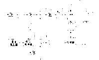
图2是PNS数字接收机的方框图;Fig. 2 is the block diagram of PNS digital receiver;
图3是包括检测窄带干扰的信道的数字相干器的方框图;Figure 3 is a block diagram of a digital coherent including a channel for detecting narrowband interference;
图4是数字相干器的跟踪信道的方框图;Figure 4 is a block diagram of a tracking channel of a digital coherent;
图5是检测窄带干扰的数字相干器的信道的方框图;Figure 5 is a block diagram of a channel of a digital coherent for detecting narrowband interference;
图6是2比特四级量化器的ADC输出值的图;Fig. 6 is the graph of the ADC output value of 2-bit four-stage quantizer;
图7是2比特三级量化器的ADC输出值的图;Fig. 7 is the graph of the ADC output value of 2-bit three-stage quantizer;
本发明的优选实施例Preferred Embodiments of the Invention
图1是一个说明选择正弦干扰出现时的量化阈值的重要性的示意图。图1(a)说明查找信号PNS,图1(b)表示具有窄带干扰的PNS。可以很容易地看出量化阈值增加V2>V1,则PNS碎片增加,其可以与正弦噪声背景明确区分。Figure 1 is a schematic diagram illustrating the importance of choosing a quantization threshold in the presence of sinusoidal interference. Figure 1(a) illustrates the search signal PNS and Figure 1(b) shows the PNS with narrowband interference. It can be easily seen that increasing the quantization threshold V2 >V1 increases the PNS fragmentation, which can be clearly distinguished from the sinusoidal noise background.
图2示出PNS接收机的方框图。接收机可以按情况分为射频部分和数字部分。标准的射频部分由输入射频模块组成,该模块包括第一高频带通滤波器1,低噪声放大器2和串联并执行输入信号的初级放大和滤波的第二高频带通滤波器。放大信号在其输出连接到IF带通滤波器5的混频器4中转换为中间频率,从而抑制高频谐波。应用到混频器4的第二输入的是电压控制发生器(VCG)14的信号,电压控制发生器(VCG)依次由基准发生器11,分频器13,相位检测器12和低频16组成的AFC环路控制。电压控制发生器(VCG)14与分频器15一起作为ADC7和处理器10的操作的基准频率源。将IF滤波器5的输出信号应用到ADC6的输入,借助于数字到模拟转换器(DAC)8将数字信号转换为控制电压ADC6的放大系数由处理器控制。根据分频器13,15的分频系数的选择可将这样的射频信道电路用于GPS和GLONASS信号。AGC电路放大的模拟信号在多级模拟到数字转换器7被数字化。ADC7具有控制量化阈值的值的控制输入,ADC7经DAC8连接到处理器10的输出。在数字化之后该信号用于多信道相干器9的输入,多信道相干器9执行具体PNS的跟踪和解码并检测窄带干扰。处理器10从存储相干器9的正交输出的累加器读取信息,通过确定GPS代码序列和GLONASS的分配频率的组合控制跟踪信道的操作,通过关闭跟踪频率的周期及代码设定主发生器的频率和相干器信道的代码发生器的频率,产生控制AGC6的增益并设定ADC7的量化阈值的数字控制信号。该数字控制信号在双DAC8中被转换为模拟信号。由于处于恒定量化阈值的AGC内的放大改变等效于处于恒定放大级的ADC阈值的改变,所以控制AGC或ADC的阈值的方案也是可能的。然而,前者的方案更为可取,因为其可以提供灵活的控制。例如,通过控制ADC阈值,有可能补偿模拟电路的零漂移。ADC7可用作一个正交,或实数量化器。在给定实例,考虑一个实数ADC。Figure 2 shows a block diagram of a PNS receiver. The receiver can be divided into radio frequency part and digital part according to the situation. The standard RF section consists of an input RF module comprising a first high
图3是数字相干器的方框图。该相干器包括一组相同的跟踪信道17,每个信道跟踪其本身的PNS,和一个检测窄带干扰的信道18,以及一个统计模块19。统计模块19计算在一个具体的时间区间内落入每个量化区间的ADC输出的计数,例如,三级ADC输出的0,+1,-1的计数量。统计模块的计数由处理器读出。检测窄带干扰的信道形成相干器的累加器的正交输出的计数以用于处理器20的输入。图4是跟踪信道的方框图。应用到该信道的输入是一个数字信号,该信号可从两个射频信道:GPS和GLONASS的输出得到。在输入信号切换电路21选择所要求的信道,将其与正交混频器23,24内的载波发生器22的数字信号混频。接着具有消除载波的该信号的正交分量与代码序列(P)的准确副本相乘,以及与乘法器27,28内的信号(E-L)的差值(早-减-晚)副本相乘。由于下面操作的结果形成伪随机编码序列的副本:代码-频率发生器29形成用于PCS发生器30的输入的一列时钟脉冲,PCS发生器30借助于伪随机序列(PCS)的唯一代码调制时钟列。所产生的时钟列输入延迟PCS脉冲形成电路31的输入,在跟踪模式延迟PCS脉冲形成电路31在输出形成准时和差分PCS。在查找模式脉冲形成延迟PCS31形成PCS信号的早和晚的副本。借助于信道控制寄存器32控制信道的操作模式,信道控制寄存器32的输入通过双向总线37连接到处理器并且其输出连接到确定信道操作的单元21,22,29,30,31。来自乘法器25,26,27,28的输出的相干结果存储在累加器33,34,35,36,从这里被处理器通过数据总线37读取。为检查查找和跟踪,处理器执行记录和从单元22,29,30,32读取的操作。在操作期间处理器执行到跟踪信道的各个单元的信息记录和从跟踪信道的各个单元的信息读取的操作。控制信道32的寄存器包含系统(GPS/GLONASS)信息和信道操作(查找/诊断)模式信息,这些信息由处理器读取,处理器通过检查信道操作可以改变这些寄存器参数。载波发生器22产生处理器在测量时刻输出的载波频率的全部相位。接着,处理器将新的频率值记录到载波发生器,从而控制频率跟踪过程。代码频率发生器29计算测量时刻的代码的全部相位,将其输入到处理器并定义伪-范围。接着,处理器将新的频率代码值记录到发生器,执行代码跟踪过程。PCS发生器30包括形成二进制伪噪声序列的寄存器,该序列可由处理器读出并修改,从而允许系统指定跟踪具体PNS的信道。Figure 3 is a block diagram of a digital coherent. The correlator comprises a set of
图5所示为检测信道的窄带干扰的方框图。可以看出该给定信道为一个跟踪信道的简单电路。来自输入信号切换电路38输出的数字信号应用到正交混频器40,41的输入,其中该数字信号与数字载波发生器39的正交输出相乘。相关结果存储在累加器42,43并且可由处理器通过总线44读出。Figure 5 shows a block diagram for detecting narrowband interference on a channel. It can be seen that the given channel is a simple circuit that tracks the channel. The digital signal from the output of the input signal switching circuit 38 is applied to the input of the quadrature mixers 40 , 41 , wherein the digital signal is multiplied with the quadrature output of the digital carrier generator 39 . Correlation results are stored in accumulators 42 , 43 and can be read by the processor via bus 44 .
图5和图6描述两比特模拟到数字转换器的操作。图5示出具有加权系数±R的四比特ADC的操作。具有0<U<Δ,-Δ<U<0的信号对应于输出+1。信号Δ<U,U<-Δ对应于输出±1。信号Δ<U,U<Δ对应于输出±R,其中一般来说加权系数R可以变化。图6示出三级ADC的操作,其中输入U<-Δ,-Δ<U<Δ,Δ<U对应于输出-1,0,+1。Figures 5 and 6 describe the operation of the two-bit analog-to-digital converter. Figure 5 shows the operation of a four-bit ADC with weighting coefficients ±R. A signal with 0<U<Δ, -Δ<U<0 corresponds to the output +1. The signal Δ<U, U<-Δ corresponds to an output of ±1. The signal Δ<U, U<Δ corresponds to the output ±R, wherein in general the weighting factor R can vary. Fig. 6 shows the operation of a three-stage ADC, where the input U<-Δ, -Δ<U<Δ, Δ<U corresponds to the output -1, 0, +1.
这样,从上面所述可以清楚看出,所声明的用于全球定位系统的数字接收机在技术上可行,具有实用性和说服力,并决定在窄带干扰影响下系统GSP和GLONASS的伪噪声信号的有效接收的技术任务。Thus, it is clear from the above that the declared digital receiver for GPS is technically feasible, practical and convincing and determines the pseudo-noise signals of the systems GSP and GLONASS under the influence of narrowband interference Effectively received technical tasks.
Claims (3)
Translated fromChineseApplications Claiming Priority (1)
| Application Number | Priority Date | Filing Date | Title |
|---|---|---|---|
| PCT/RU1998/000230WO2000005741A1 (en) | 1998-07-20 | 1998-07-20 | Multiple-channel digital receiver for global positioning system |
Publications (2)
| Publication Number | Publication Date |
|---|---|
| CN1270700Atrue CN1270700A (en) | 2000-10-18 |
| CN1156994C CN1156994C (en) | 2004-07-07 |
Family
ID=20130240
Family Applications (1)
| Application Number | Title | Priority Date | Filing Date |
|---|---|---|---|
| CNB988092875AExpired - Fee RelatedCN1156994C (en) | 1998-07-20 | 1998-07-20 | Multi-channel digital receiver for GPS |
Country Status (7)
| Country | Link |
|---|---|
| US (1) | US6816539B1 (en) |
| EP (1) | EP1061545B1 (en) |
| JP (1) | JP4011854B2 (en) |
| KR (1) | KR100506198B1 (en) |
| CN (1) | CN1156994C (en) |
| AU (1) | AU754361B2 (en) |
| WO (1) | WO2000005741A1 (en) |
Cited By (11)
| Publication number | Priority date | Publication date | Assignee | Title |
|---|---|---|---|---|
| CN100361399C (en)* | 2005-02-04 | 2008-01-09 | 宁波日兴电子有限公司 | FM wireless transmission outdoor sound system |
| CN100397800C (en)* | 2002-07-18 | 2008-06-25 | SiRF技术公司 | Method and apparatus for detecting jamming signa in a DSSS system using phase transition counting |
| CN101101216B (en)* | 2006-07-05 | 2010-05-12 | 中国农业大学 | Navigation Path Recognition Method of Sprayer in Cotton Field |
| CN101051081B (en)* | 2006-04-05 | 2011-02-09 | 中国科学院微电子研究所 | Variable-gain high-sensitivity GPS receiver baseband frequency tracking method |
| CN101300501B (en)* | 2005-11-08 | 2012-02-08 | 纳夫科姆技术公司 | Sampling threshold and gain for satellite navigation receiver |
| CN1963557B (en)* | 2005-11-09 | 2012-03-07 | 精工爱普生株式会社 | Positioning apparatus, control method of positioning apparatus |
| CN101487882B (en)* | 2001-11-02 | 2012-06-20 | Qx有限公司 | Frequency coherence within a location network |
| CN102788983A (en)* | 2010-05-31 | 2012-11-21 | 北京联星科通微电子技术有限公司 | GPS and Glonass multichannel parallel signal tracing method and correlator |
| CN110022162A (en)* | 2017-12-21 | 2019-07-16 | 泰勒斯公司 | Signal receiver, particularly GNSS signal receiver including interference suppression filter and associated method |
| CN111399001A (en)* | 2020-03-31 | 2020-07-10 | 和芯星通科技(北京)有限公司 | Method and device for processing broadband interference |
| CN111758221A (en)* | 2017-10-03 | 2020-10-09 | 硕威技术有限公司 | Signal processing system and method |
Families Citing this family (24)
| Publication number | Priority date | Publication date | Assignee | Title |
|---|---|---|---|---|
| JP3981899B2 (en)* | 1998-02-26 | 2007-09-26 | ソニー株式会社 | Transmission method, transmission device, and reception device |
| FI20010952A0 (en)* | 2001-05-07 | 2001-05-07 | Nokia Corp | Separation of signal components in a radio system receiver |
| US6775605B2 (en) | 2001-11-29 | 2004-08-10 | Ford Global Technologies, Llc | Remote sensing based pre-crash threat assessment system |
| FR2837638B1 (en) | 2002-03-22 | 2006-07-14 | Thales Sa | SIGNAL PROCESSING METHOD IN THE PRESENCE OF INTERFERENCE |
| US7801481B2 (en)* | 2005-11-08 | 2010-09-21 | Navcom Technology, Inc. | Satellite navigation receiver signal processing architecture |
| GB2436178A (en)* | 2006-03-13 | 2007-09-19 | Matsushita Electric Industrial Co Ltd | A scheme to alleviate signal degradation caused by digital gain control loops. |
| EP1901085B1 (en)* | 2006-09-12 | 2014-05-28 | u-blox AG | GNSS Receiver IC package |
| CN101212779B (en)* | 2006-12-31 | 2011-04-20 | 上海真灼电子技术有限公司 | Processing method against signal overlay in guide and navigation system |
| FR2916589A1 (en)* | 2007-05-25 | 2008-11-28 | Thales Sa | AUTOMATIC GAIN CONTROL SERVICED ON THE DENSITY OF PROBABILITY OF RECEIVED POWER |
| TW200925639A (en)* | 2007-12-14 | 2009-06-16 | Altek Corp | GPS module testing system capable of adjusting testing signal automatically |
| CN101286757B (en)* | 2008-04-10 | 2011-07-20 | 杭州国芯科技股份有限公司 | Anti-jamming method and device in phase tracing |
| US8217833B2 (en)* | 2008-12-11 | 2012-07-10 | Hemisphere Gps Llc | GNSS superband ASIC with simultaneous multi-frequency down conversion |
| KR100986753B1 (en) | 2009-07-24 | 2010-10-08 | 엘아이지넥스원 주식회사 | The system for detecting pulse singnal and the method thereof |
| CN102004236B (en)* | 2009-08-28 | 2012-12-26 | 上海伽利略导航有限公司 | Global position system (GPS) signal tracking method, tracking channel loop and adjusting method thereof |
| US8410979B2 (en) | 2010-01-25 | 2013-04-02 | Qualcomm Incorporated | Digital front end in system simultaneously receiving GPS and GLONASS signals |
| US8587477B2 (en)* | 2010-01-25 | 2013-11-19 | Qualcomm Incorporated | Analog front end for system simultaneously receiving GPS and GLONASS signals |
| US8018379B1 (en)* | 2010-01-25 | 2011-09-13 | Qualcomm Atheros, Inc. | Automatic gain control in system simultaneously receiving GPS and GLONASS signals |
| US8681045B2 (en) | 2010-07-09 | 2014-03-25 | Intel Mobile Communications GmbH | Hybrid satellite positioning receiver |
| EP2792097B1 (en) | 2011-12-13 | 2025-03-05 | Northrop Grumman Guidance and Electronics Company, Inc. | Systems and methods for adaptive sample quantization |
| EP2814197B1 (en)* | 2013-06-13 | 2017-10-18 | Airbus Defence and Space GmbH | Method for carrier-to-noise ratio estimation in GNSS receivers |
| US9094392B1 (en)* | 2013-10-28 | 2015-07-28 | Rockwell Collins, Inc. | GNSS receiver autonomous signal authentication using signal stability analysis system and related method |
| CN105099588B (en)* | 2015-09-06 | 2017-08-29 | 南京航空航天大学 | Aviation communication system interferencing propagation channel simulation device and method |
| US10389464B2 (en) | 2016-04-28 | 2019-08-20 | Samsung Electronics Co., Ltd | System and method for improved data decoding, tracking, and other receiver functions in the presence of interference |
| CN113702804B (en)* | 2021-07-26 | 2024-02-09 | 西安空间无线电技术研究所 | A correlation error correction method in multi-channel digital correlator |
Family Cites Families (4)
| Publication number | Priority date | Publication date | Assignee | Title |
|---|---|---|---|---|
| US3605018A (en)* | 1968-09-13 | 1971-09-14 | Sylvania Electric Prod | Interference suppression in a receiver by envelope variation modulation |
| US4426712A (en)* | 1981-05-22 | 1984-01-17 | Massachusetts Institute Of Technology | Correlation system for global position receiver |
| US5222106A (en)* | 1990-02-07 | 1993-06-22 | Kokusai Denshin Denwa Kabushiki Kaisha | Interference detection and reduction |
| US6133876A (en)* | 1998-03-23 | 2000-10-17 | Time Domain Corporation | System and method for position determination by impulse radio |
- 1998
- 1998-07-20AUAU14475/99Apatent/AU754361B2/ennot_activeCeased
- 1998-07-20WOPCT/RU1998/000230patent/WO2000005741A1/ennot_activeCeased
- 1998-07-20KRKR10-2000-7002967Apatent/KR100506198B1/ennot_activeExpired - Fee Related
- 1998-07-20USUS09/508,936patent/US6816539B1/ennot_activeExpired - Fee Related
- 1998-07-20JPJP2000561639Apatent/JP4011854B2/ennot_activeExpired - Fee Related
- 1998-07-20EPEP98958418Apatent/EP1061545B1/ennot_activeExpired - Lifetime
- 1998-07-20CNCNB988092875Apatent/CN1156994C/ennot_activeExpired - Fee Related
Cited By (12)
| Publication number | Priority date | Publication date | Assignee | Title |
|---|---|---|---|---|
| CN101487882B (en)* | 2001-11-02 | 2012-06-20 | Qx有限公司 | Frequency coherence within a location network |
| CN100397800C (en)* | 2002-07-18 | 2008-06-25 | SiRF技术公司 | Method and apparatus for detecting jamming signa in a DSSS system using phase transition counting |
| CN100361399C (en)* | 2005-02-04 | 2008-01-09 | 宁波日兴电子有限公司 | FM wireless transmission outdoor sound system |
| CN101300501B (en)* | 2005-11-08 | 2012-02-08 | 纳夫科姆技术公司 | Sampling threshold and gain for satellite navigation receiver |
| CN1963557B (en)* | 2005-11-09 | 2012-03-07 | 精工爱普生株式会社 | Positioning apparatus, control method of positioning apparatus |
| CN101051081B (en)* | 2006-04-05 | 2011-02-09 | 中国科学院微电子研究所 | Variable-gain high-sensitivity GPS receiver baseband frequency tracking method |
| CN101101216B (en)* | 2006-07-05 | 2010-05-12 | 中国农业大学 | Navigation Path Recognition Method of Sprayer in Cotton Field |
| CN102788983A (en)* | 2010-05-31 | 2012-11-21 | 北京联星科通微电子技术有限公司 | GPS and Glonass multichannel parallel signal tracing method and correlator |
| CN111758221A (en)* | 2017-10-03 | 2020-10-09 | 硕威技术有限公司 | Signal processing system and method |
| CN111758221B (en)* | 2017-10-03 | 2023-02-10 | 硕威技术有限公司 | Signal processing systems and methods |
| CN110022162A (en)* | 2017-12-21 | 2019-07-16 | 泰勒斯公司 | Signal receiver, particularly GNSS signal receiver including interference suppression filter and associated method |
| CN111399001A (en)* | 2020-03-31 | 2020-07-10 | 和芯星通科技(北京)有限公司 | Method and device for processing broadband interference |
Also Published As
| Publication number | Publication date |
|---|---|
| EP1061545A4 (en) | 2005-07-06 |
| JP2002521677A (en) | 2002-07-16 |
| JP4011854B2 (en) | 2007-11-21 |
| CN1156994C (en) | 2004-07-07 |
| US6816539B1 (en) | 2004-11-09 |
| AU1447599A (en) | 2000-02-14 |
| KR20010030635A (en) | 2001-04-16 |
| AU754361B2 (en) | 2002-11-14 |
| EP1061545B1 (en) | 2006-10-04 |
| KR100506198B1 (en) | 2005-08-08 |
| WO2000005741A1 (en) | 2000-02-03 |
| EP1061545A1 (en) | 2000-12-20 |
Similar Documents
| Publication | Publication Date | Title |
|---|---|---|
| CN1270700A (en) | Multi-channel digital receiver for GPS | |
| Sharawi et al. | GPS C/N/sub 0/estimation in the presence of interference and limited quantization levels | |
| JP4757425B2 (en) | Code phase tracking method and receiver | |
| US6441780B1 (en) | Receiver for pseudo-noise signals from a satellite radio-navigation systems | |
| US5734674A (en) | Pseudorandom-noise receiver having automatic switching between regular and anti-jamming modes | |
| US4426712A (en) | Correlation system for global position receiver | |
| US20070024499A1 (en) | Method of Cross-Correlation and Continuous Wave Interference Suppression for GPS Signal and Associated GPS Receiver | |
| CN101432635A (en) | Adaptive code generator for satellite navigation receivers | |
| KR100547764B1 (en) | Method of Increasing the Noise Immunity of Reception of Signals of Satellite Navigational System and Device for realizing the same | |
| JPH04269682A (en) | Multichannel digital receiver for global position detecting system | |
| KR20160106749A (en) | A processor for a radio receiver | |
| CN116636151A (en) | Adaptive narrowband and wideband interference suppression for satellite navigation receivers | |
| EP1051810A1 (en) | Receiver for ds-cdma signals in satellite navigation systems | |
| CA2255494C (en) | A method of processing signals of a satellite positioning system | |
| US7336736B2 (en) | Method of detecting and processing pulsed signals in a radio signal | |
| Hrbek et al. | Filtering and quantization effects on GNSS successive interference cancellation | |
| KR20010094752A (en) | Method and apparatus for code phase correlation | |
| KR100905338B1 (en) | Digital signal correlation methods, computer readable storage media, electronic devices and GPS receivers | |
| KR100810802B1 (en) | Generation method of time shifted signal | |
| Deshpande et al. | Analysis of the effects of GPS receiver acquisition parameters | |
| Thompson et al. | USE OF agc in MITIGATION of continous-wave interference IN GNSS RECEIVERS |
Legal Events
| Date | Code | Title | Description |
|---|---|---|---|
| C06 | Publication | ||
| PB01 | Publication | ||
| C10 | Entry into substantive examination | ||
| SE01 | Entry into force of request for substantive examination | ||
| C14 | Grant of patent or utility model | ||
| GR01 | Patent grant | ||
| C17 | Cessation of patent right | ||
| CF01 | Termination of patent right due to non-payment of annual fee | Granted publication date:20040707 |