CN1263339A - Optical head device, recording/reproducing device, optical element, and information recording/reproducing method - Google Patents
Optical head device, recording/reproducing device, optical element, and information recording/reproducing methodDownload PDFInfo
- Publication number
- CN1263339A CN1263339ACN00104175ACN00104175ACN1263339ACN 1263339 ACN1263339 ACN 1263339ACN 00104175 ACN00104175 ACN 00104175ACN 00104175 ACN00104175 ACN 00104175ACN 1263339 ACN1263339 ACN 1263339A
- Authority
- CN
- China
- Prior art keywords
- optical
- information recording
- light
- objective lens
- recording medium
- Prior art date
- Legal status (The legal status is an assumption and is not a legal conclusion. Google has not performed a legal analysis and makes no representation as to the accuracy of the status listed.)
- Granted
Links
Images


Classifications
- G—PHYSICS
- G11—INFORMATION STORAGE
- G11B—INFORMATION STORAGE BASED ON RELATIVE MOVEMENT BETWEEN RECORD CARRIER AND TRANSDUCER
- G11B7/00—Recording or reproducing by optical means, e.g. recording using a thermal beam of optical radiation by modifying optical properties or the physical structure, reproducing using an optical beam at lower power by sensing optical properties; Record carriers therefor
- G11B7/12—Heads, e.g. forming of the optical beam spot or modulation of the optical beam
- G11B7/135—Means for guiding the beam from the source to the record carrier or from the record carrier to the detector
- G11B7/1353—Diffractive elements, e.g. holograms or gratings
- E—FIXED CONSTRUCTIONS
- E05—LOCKS; KEYS; WINDOW OR DOOR FITTINGS; SAFES
- E05B—LOCKS; ACCESSORIES THEREFOR; HANDCUFFS
- E05B49/00—Electric permutation locks; Circuits therefor ; Mechanical aspects of electronic locks; Mechanical keys therefor
- E—FIXED CONSTRUCTIONS
- E05—LOCKS; KEYS; WINDOW OR DOOR FITTINGS; SAFES
- E05B—LOCKS; ACCESSORIES THEREFOR; HANDCUFFS
- E05B47/00—Operating or controlling locks or other fastening devices by electric or magnetic means
- G—PHYSICS
- G11—INFORMATION STORAGE
- G11B—INFORMATION STORAGE BASED ON RELATIVE MOVEMENT BETWEEN RECORD CARRIER AND TRANSDUCER
- G11B7/00—Recording or reproducing by optical means, e.g. recording using a thermal beam of optical radiation by modifying optical properties or the physical structure, reproducing using an optical beam at lower power by sensing optical properties; Record carriers therefor
- G11B7/12—Heads, e.g. forming of the optical beam spot or modulation of the optical beam
- G11B7/125—Optical beam sources therefor, e.g. laser control circuitry specially adapted for optical storage devices; Modulators, e.g. means for controlling the size or intensity of optical spots or optical traces
- G11B7/127—Lasers; Multiple laser arrays
- G11B7/1275—Two or more lasers having different wavelengths
- G—PHYSICS
- G11—INFORMATION STORAGE
- G11B—INFORMATION STORAGE BASED ON RELATIVE MOVEMENT BETWEEN RECORD CARRIER AND TRANSDUCER
- G11B7/00—Recording or reproducing by optical means, e.g. recording using a thermal beam of optical radiation by modifying optical properties or the physical structure, reproducing using an optical beam at lower power by sensing optical properties; Record carriers therefor
- G11B7/12—Heads, e.g. forming of the optical beam spot or modulation of the optical beam
- G11B7/135—Means for guiding the beam from the source to the record carrier or from the record carrier to the detector
- G11B7/1372—Lenses
- G11B7/1374—Objective lenses
- G—PHYSICS
- G11—INFORMATION STORAGE
- G11B—INFORMATION STORAGE BASED ON RELATIVE MOVEMENT BETWEEN RECORD CARRIER AND TRANSDUCER
- G11B7/00—Recording or reproducing by optical means, e.g. recording using a thermal beam of optical radiation by modifying optical properties or the physical structure, reproducing using an optical beam at lower power by sensing optical properties; Record carriers therefor
- G11B7/12—Heads, e.g. forming of the optical beam spot or modulation of the optical beam
- G11B7/135—Means for guiding the beam from the source to the record carrier or from the record carrier to the detector
- G11B7/139—Numerical aperture control means
- G—PHYSICS
- G11—INFORMATION STORAGE
- G11B—INFORMATION STORAGE BASED ON RELATIVE MOVEMENT BETWEEN RECORD CARRIER AND TRANSDUCER
- G11B7/00—Recording or reproducing by optical means, e.g. recording using a thermal beam of optical radiation by modifying optical properties or the physical structure, reproducing using an optical beam at lower power by sensing optical properties; Record carriers therefor
- G11B7/12—Heads, e.g. forming of the optical beam spot or modulation of the optical beam
- G11B7/135—Means for guiding the beam from the source to the record carrier or from the record carrier to the detector
- G11B7/1392—Means for controlling the beam wavefront, e.g. for correction of aberration
- G11B7/13922—Means for controlling the beam wavefront, e.g. for correction of aberration passive
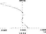
- E—FIXED CONSTRUCTIONS
- E05—LOCKS; KEYS; WINDOW OR DOOR FITTINGS; SAFES
- E05B—LOCKS; ACCESSORIES THEREFOR; HANDCUFFS
- E05B47/00—Operating or controlling locks or other fastening devices by electric or magnetic means
- E05B2047/0084—Key or electric means; Emergency release
- E05B2047/0086—Emergency release, e.g. key or electromagnet
- E05B2047/0087—Electric spare devices, e.g. auxiliary batteries or capacitors for back up
- G—PHYSICS
- G11—INFORMATION STORAGE
- G11B—INFORMATION STORAGE BASED ON RELATIVE MOVEMENT BETWEEN RECORD CARRIER AND TRANSDUCER
- G11B7/00—Recording or reproducing by optical means, e.g. recording using a thermal beam of optical radiation by modifying optical properties or the physical structure, reproducing using an optical beam at lower power by sensing optical properties; Record carriers therefor
- G11B2007/0003—Recording, reproducing or erasing systems characterised by the structure or type of the carrier
- G11B2007/0006—Recording, reproducing or erasing systems characterised by the structure or type of the carrier adapted for scanning different types of carrier, e.g. CD & DVD
Landscapes
- Physics & Mathematics (AREA)
- Optics & Photonics (AREA)
- Optical Head (AREA)
- Lenses (AREA)
- Optical Recording Or Reproduction (AREA)
- Diffracting Gratings Or Hologram Optical Elements (AREA)
- Glass Compositions (AREA)
- Lubricants (AREA)
Abstract
Description
Translated fromChinese本发明涉及一种光学头装置、带有这种光学头装置的记录/再现装置、光学元件及信息记录/再现方法。The present invention relates to an optical head device, a recording/reproducing device having the optical head device, an optical element, and an information recording/reproducing method.
最近,作为短波长红色激光器的实际应用,具有与CD(致密盘)几乎相同的尺寸但具有更大容量的高密度光信息记录媒体(也称为光盘)DVD投入生产。在DVD记录/再现装置中,使用650nm的半导体激光器时物镜的光盘一侧上的数值孔径NA为0.6-0.65。DVD具有0.74μm的光道间距和0.4μm的最小信号坑长度,并且处于致密化状态,其中尺寸比具有1.6μm的光道间距和0.83μm的最小信号坑长度的CD的一半还低。另外,在DVD中,为了把光盘相对光轴倾斜时产生的彗差降低到很小,透明衬底的厚度为0.6mm,是CD的透明衬底的厚度的一半。Recently, as a practical application of short-wavelength red lasers, DVDs, which are high-density optical information recording media (also called optical discs) having almost the same size as CDs (Compact Discs) but with larger capacities, have been put into production. In a DVD recording/reproducing apparatus, the numerical aperture NA on the disc side of the objective lens is 0.6-0.65 when a semiconductor laser of 650 nm is used. A DVD has a track pitch of 0.74 μm and a minimum pit length of 0.4 μm, and is in a densified state with dimensions less than half that of a CD with a track pitch of 1.6 μm and a minimum pit length of 0.83 μm. In addition, in DVD, in order to minimize the coma aberration that occurs when the disc is tilted relative to the optical axis, the thickness of the transparent substrate is 0.6 mm, which is half the thickness of the transparent substrate of CD.
另外,除上述CD或DVD之外,光源波长或透明衬底厚度不同的各种标准的光盘如CD-R、RW(附录型致密盘)、VD(视频盘)、MD(小型盘)、MO(光电磁盘)等也进入市场并广为传播。另外,半导体激光器的波长被进一步缩短,具有大约400nm的发出波长的短波长蓝色激光器正被投入实际应用。当波长被缩短时,即使使用与DVD相同的数值孔径,光信息记录媒体的容量也会被进一步提高。In addition, in addition to the above-mentioned CD or DVD, optical discs of various standards such as CD-R, RW (Appendix Compact Disc), VD (Video Disc), MD (Mini Disc), MO (optical disks) etc. have also entered the market and spread widely. In addition, the wavelength of semiconductor lasers is further shortened, and short-wavelength blue lasers having an emission wavelength of about 400 nm are being put into practical use. When the wavelength is shortened, the capacity of the optical information recording medium can be further increased even with the same numerical aperture as DVD.
此外,在与上述传统光信息记录媒体CD相同的尺寸中,多种光信息记录媒体的开发在推进,如可执行记录和再现的CD-R、记录面的透明衬底厚度不同或者用于记录和再现的激光的波长不同的记录密度被提高的DVD的开发,因此,要求能对这些光信息记录媒体由同一光学头执行记录和再现。从而,建议了各种光学头,其具有相应于使用波长的多个激光源,通过这些激光源经必要的数值孔径由同一物镜把激光会聚到记录面上(例如,日本特开平8-55363和10-92010等)。In addition, in the same size as the above-mentioned conventional optical information recording medium CD, the development of various optical information recording media is advancing, such as CD-R that can perform recording and reproduction, a transparent substrate with a different thickness on the recording surface, or for recording In the development of DVDs in which the recording density is increased differently from the wavelength of laser light to be reproduced, it is required that recording and reproduction can be performed on these optical information recording media by the same optical head. Thereby, various optical heads have been suggested, which have a plurality of laser light sources corresponding to the wavelengths used, by which the laser light is converged onto the recording surface by the same objective lens through a necessary numerical aperture (for example, Japanese Patent Laid-Open No. 8-55363 and 10-92010, etc.).
在上面的说明中,在日本特开平9-54973中,公开了使用全息光学元件的光学系统,其中应用635nm的透射光(零阶衍射光线)和785nm的负一阶衍射光线;和使用全息光学系统的光学系统,其中应用635nm的正一阶衍射光线和785nm的透射光(零阶衍射光线)。另外,日本特开平10-283668中,公开了一种波长为650nm、全息环形透镜以100%透射并且780nm的光被全息环形透镜一阶衍射的光学系统。In the above description, in Japanese Patent Laid-Open No. 9-54973, an optical system using a holographic optical element is disclosed, in which transmitted light (zero-order diffracted light) of 635 nm and negative first-order diffracted light of 785 nm are applied; The optical system of the system, wherein positive first-order diffracted rays of 635 nm and transmitted light (zero-order diffracted rays) of 785 nm are applied. In addition, Japanese Patent Application Laid-Open No. 10-283668 discloses an optical system in which the wavelength is 650 nm, the holographic annular lens transmits 100%, and the light of 780 nm is first-order diffracted by the holographic annular lens.
但是,在这些全息元件和全息型环形透镜中,当对于一侧的波长而言,零阶光的衍射效率为100%时,对于另一侧的波长,正一阶衍射光线或负一阶衍射光线的衍射效率必定受到限制,从而不能获得所需的高衍射效率,引起光量的损失,使用光量的效率变坏而出现问题。当引起光量的损失时,需要大功率的激光器,尤其是在信息记录时。However, in these hologram elements and hologram ring lenses, when the diffraction efficiency of zero-order light is 100% for one wavelength, positive first-order diffracted rays or negative first-order diffracted rays are The diffraction efficiency of light is necessarily limited, so that a desired high diffraction efficiency cannot be obtained, resulting in a loss of light quantity, and a problem arises due to deterioration in the efficiency of using light quantity. When loss of light quantity is caused, a high-power laser is required, especially at the time of information recording.
另外,在全息元件和全息型环形透镜中,当对于一侧的波长零阶光的衍射效率为100%,并且对于另一侧的波长,通过尽可能防止零阶光被透射而使正一阶衍射光线或负一阶衍射光线的衍射效率变大时,全息图已经被作成3.8-5.18μm那么深。因此,当全息光学元件或全息型环形透镜的功能特别是集成在物镜中时,处理金属模具和模塑变得困难,这已经成为一个问题。In addition, in a hologram element and a hologram-type ring lens, when the diffraction efficiency of zero-order light for one wavelength is 100%, and for the other wavelength, the positive first-order is made by preventing zero-order light from being transmitted as much as possible. When the diffraction efficiency of diffracted rays or negative first-order diffracted rays becomes larger, the hologram has been made as deep as 3.8-5.18 μm. Therefore, when the function of a hologram optical element or a hologram-type ring lens is integrated in an objective lens in particular, it becomes difficult to handle a metal mold and molding, which has become a problem.
另外,本发明人原来建议了一种物镜(日本特愿平9-286954),其中构造了一种由多个被分割为同心圆的分割表面构成的光学头,各个分割表面进行象差校正而达到具有不同波长的多个光源和/或具有记录面的不同厚度的透明衬底的衍射极限,并且结构简单。这种物镜具有一种功能,通过它可自动获得相应于使用波长和/或透明衬底的厚度的必要的孔径。但是,当使用其中激光源和光检测器被集成起来的激光器/检测器集成单元时,有由于弥散光进入光检测器而致使检测不能正确进行的情况发生,从而出现问题。尤其在通过利用全息技术偏斜光通量并将之引入光检测器的类型的激光器/检测器集成单元中这个问题显著。此外,当在DVD系统(DVD-RAM、DVD-R、DVD-RW、DVD+R等)的可记录盘或CD系统(CD-R、CD-RW等)的可记录盘中执行高速记录时,由于局部光束弥散,与使用专用透镜的光学系统相比,该光量的使用效率很差,因此必须提高激光源的功率。In addition, the present inventor originally proposed an objective lens (Japanese Patent Application No. Hei 9-286954) in which an optical head composed of a plurality of divided surfaces divided into concentric circles is constructed, and the aberration correction is performed on each divided surface. The diffraction limit of multiple light sources with different wavelengths and/or transparent substrates with different thicknesses of the recording surface is reached, and the structure is simple. Such an objective lens has a function by which a necessary aperture corresponding to the wavelength used and/or the thickness of the transparent substrate is automatically obtained. However, when a laser/detector integrated unit in which a laser light source and a photodetector are integrated is used, detection may not be performed correctly due to stray light entering the photodetector, thereby causing a problem. This problem is notable especially in laser/detector integrated units of the type that deflects the light flux by utilizing holographic techniques and directs it to the photodetector. Also, when performing high-speed recording on recordable discs of the DVD system (DVD-RAM, DVD-R, DVD-RW, DVD+R, etc.) or CD systems (CD-R, CD-RW, etc.) , due to localized beam dispersion, this amount of light is used poorly compared to optical systems using dedicated lenses, so the power of the laser source must be increased.
对于使用的波长和透明衬底厚度彼此不同的DVD和CD,提出了各种可互换的光学系统,其中一个物镜被用于记录和/或再现信息而不产生大的球差或色差。但是,实际应用中的光学系统被构造为来自光源的发散光的光通量的发散程度通过耦合物镜被弱化,或者使得发散光的光通量成为平行光通量或成为弱发散光的光通量,并且光通量经物镜和光信息记录媒体的透明衬底被会聚到信息记录面上,因此需要耦合透镜和物镜两个透镜。因此,难以把光学头装置的大小减小到很小很薄,并且还有成本提高的问题。For DVDs and CDs that use different wavelengths and transparent substrate thicknesses from each other, various interchangeable optical systems have been proposed in which one objective lens is used for recording and/or reproducing information without large spherical aberration or chromatic aberration. However, the optical system in practical application is constructed so that the divergence degree of the luminous flux of the divergent light from the light source is weakened by coupling the objective lens, or the luminous flux of the divergent light becomes a parallel luminous flux or a luminous flux of weakly divergent light, and the luminous flux passes through the objective lens and the optical information The transparent substrate of the recording medium is converged to the information recording surface, so two lenses, a coupling lens and an objective lens, are required. Therefore, it is difficult to reduce the size of the optical pickup device to be small and thin, and there is also a problem of cost increase.
另一方面,如上所述,广为使用除CD和DVD之外的各种光盘,因此,对于这些光盘而言可互换的并且结构简单的光学系统和带有这种光学系统的光学头装置是必要的。On the other hand, as described above, various optical discs other than CD and DVD are widely used, and therefore, an optical system that is interchangeable for these optical discs and has a simple structure and an optical head device with such an optical system necessary.
本发明的目的是提供一种光学头装置、一种记录和再现装置、一种光学元件以及记录和再现方法,其中一种光学头装置可对使用至少两种不同波长的光线的不同类型光信息记录媒体执行记录和/或再现。It is an object of the present invention to provide an optical head device, a recording and reproducing device, an optical element, and a recording and reproducing method, wherein an optical head device can process different types of optical information using light rays of at least two different wavelengths. The recording medium performs recording and/or reproduction.
另一个目的是对于各个不同光信息记录媒体可使信息记录和/或信息再现由一个光学头装置来执行而且甚至在使用具有至少两种不同波长的光并应用于不同类型的光信息记录媒体的情况下都不产生严重的球差和色差。此外,另一个目的是提供一种具有简单结构的光学头装置。尤其,当使用不同类型的各自具有不同厚度的透明衬底的光信息记录媒体时,球差问题变得很严重。另一个目的是用一个光学头装置可对不同类型的光信息记录媒体进行信息的记录和/或再现而不产生严重的球差和色差,甚至是在前述的情况中也不产生。Another object is to enable information recording and/or information reproduction to be performed by one optical head device for each of different optical information recording media and even when using light having at least two different wavelengths and applied to different types of optical information recording media There is no serious spherical aberration and chromatic aberration under any circumstances. Furthermore, another object is to provide an optical pickup device having a simple structure. In particular, when different types of optical information recording media each having a transparent substrate of a different thickness are used, the problem of spherical aberration becomes serious. Another object is to record and/or reproduce information on different types of optical information recording media with one optical pickup device without serious spherical and chromatic aberrations even in the aforementioned cases.
另外,还有一个目的是通过光检测器的光检测可满意地进行并且检测中的S状弯曲特性可做到令人满意,甚至是在光学头装置使用由多个激光器和多个检测器组成的集成单元的情况下也不会产生对光检测器的检测有负面影响的弥散光的辐射。而且,提供光量损失更小并且光量使用效率良好的光学头装置、记录和再现装置、光学元件以及记录和再现方法也是本发明的目的。In addition, there is another object that the light detection by the photodetector can be performed satisfactorily and the S-shaped bending characteristic in the detection can be achieved satisfactorily, even when the optical head device is used consisting of a plurality of lasers and a plurality of detectors In the case of an integrated unit, no radiation of stray light, which would negatively affect the detection by the photodetector, is produced. Furthermore, it is also an object of the present invention to provide an optical head device, a recording and reproducing device, an optical element, and a recording and reproducing method with less loss of light quantity and good light quantity usage efficiency.
上述目的可通过下面的结构和方法来实现。The above object can be achieved by the following structures and methods.
(1)一种用于再现来自光信息记录媒体的信息或者用于把信息记录到光信息记录媒体上的光学头装置,包括:(1) An optical head device for reproducing information from an optical information recording medium or for recording information on an optical information recording medium, comprising:
用于发出具有第一波长的第一光通量的第一光源;a first light source for emitting a first luminous flux having a first wavelength;
用于发出具有第二波长的第二光通量的第二光源,第一波长不同于第二波长;a second light source for emitting a second luminous flux having a second wavelength, the first wavelength being different from the second wavelength;
具有光轴和衍射部分的会聚光学系统;converging optical system with optical axis and diffractive part;
光检测器;light detector;
其特征在于在第一光通量通过衍射部分产生至少一个衍射光线的情况下,第一光通量的n阶衍射光线的光量大于第一光通量的任何其它阶衍射光线的光量,在第二光通量通过衍射部分产生至少一个衍射光线的情况下,第二光通量的n阶衍射光线的量大于第二光通量的任何其它阶衍射光线的量,其中n代表非零整数。It is characterized in that when the first luminous flux passes through the diffraction part to generate at least one diffracted ray, the light quantity of the n-order diffracted ray of the first luminous flux is greater than the light quantity of any other order diffracted ray of the first luminous flux, and when the second luminous flux passes through the diffracted part to generate In the case of at least one diffracted ray, the amount of nth order diffracted rays of the second luminous flux is greater than the amount of any other order of diffracted rays of the second luminous flux, where n represents a non-zero integer.
(2)一种用于再现来自光信息记录媒体的信息或把信息记录在光信息记录媒体上的光学头装置的光学元件,包括:(2) An optical element of an optical head device for reproducing information from an optical information recording medium or recording information on an optical information recording medium, comprising:
光轴;optical axis;
衍射部分;Diffraction part;
其特征在于在第一光通量通过衍射部分产生至少一个衍射光线的情况下,第一光通量的n阶衍射光线的量大于第一光通量的任何其它阶衍射光线的量,并且在其波长不同于第一光通量的波长的第二光通量通过衍射部分产生至少一个衍射光线的情况下,第二光通量的n阶衍射光线的量大于第二光通量的任何其它阶衍射光线的量,It is characterized in that when the first luminous flux passes through the diffractive part to generate at least one diffracted ray, the amount of the n-order diffracted ray of the first luminous flux is greater than the amount of any other order diffracted ray of the first luminous flux, and the wavelength is different from that of the first In the case where the second luminous flux of the wavelength of the luminous flux passes through the diffraction part to generate at least one diffracted ray, the amount of the n-order diffracted ray of the second luminous flux is greater than the amount of any other order diffracted ray of the second luminous flux,
其中第一光通量与第二光通量的波长差是80-400nm并且n代表非零整数。Wherein the wavelength difference between the first luminous flux and the second luminous flux is 80-400 nm and n represents a non-zero integer.
(3)一种用于再现来自光信息记录媒体的信息或把信息记录在光信息记录媒体上的装置,包括:(3) An apparatus for reproducing information from or recording information on an optical information recording medium, comprising:
光学头装置,包括Optical head unit, including
用于发出具有第一波长的第一光通量的第一光源;a first light source for emitting a first luminous flux having a first wavelength;
用于发出具有第二波长的第二光通量的第二光源,第一波长不同于第二波长;a second light source for emitting a second luminous flux having a second wavelength, the first wavelength being different from the second wavelength;
具有光轴和衍射部分的会聚光学系统;converging optical system with optical axis and diffractive part;
光检测器;light detector;
其特征在于在第一光通量通过衍射部分产生至少一个衍射光线的情况下,第一光通量的n阶衍射光线的量大于第一光通量的任何其它阶衍射光线的量,并且在第二光通量通过衍射部分产生至少一个衍射光线的情况下,第二光通量的n阶衍射光线的量大于第二光通量的任何其它阶衍射光线的量,其中n代表非零整数。It is characterized in that when the first luminous flux passes through the diffraction part to generate at least one diffracted ray, the amount of the n-order diffracted ray of the first luminous flux is greater than the amount of any other order diffracted ray of the first luminous flux, and when the second luminous flux passes through the diffracted part In the case of generating at least one diffracted ray, the amount of nth order diffracted rays of the second luminous flux is greater than the amount of any other order diffracted rays of the second luminous flux, where n represents a non-zero integer.
(4)一种由包括第一光源、第二光源、光检测器和具有光轴和衍射部分的会聚光学系统的光学头装置再现来自至少两种光信息记录媒体的信息或把信息记录在其上的方法,该方法包括:(4) An optical head device reproducing information from at least two kinds of optical information recording media or recording information on it by comprising a first light source, a second light source, a photodetector and a converging optical system with an optical axis and a diffractive part method above, which includes:
从第一光源发出第一光通量或从第二光源发出第二光通量,其中第二光通量的波长不同于第一光通量的波长;emitting a first luminous flux from a first light source or a second luminous flux from a second light source, wherein the wavelength of the second luminous flux is different from the wavelength of the first luminous flux;
使第一或第二光通量通过衍射部分产生第一光通量的至少一个衍射光线或第二光通量的至少一个衍射光线,其中当第一光通量的至少一个衍射光线中n阶衍射光线的量大于第一光通量的任何其它阶衍射光线的量时,第二光通量的至少一个衍射光线中n阶衍射光线的量大于第二光通量的任何其它阶衍射光线的量,Make the first or second luminous flux pass through the diffractive part to generate at least one diffracted ray of the first luminous flux or at least one diffracted ray of the second luminous flux, wherein when the amount of the n-order diffracted ray in the at least one diffracted ray of the first luminous flux is greater than that of the first luminous flux When the amount of any other order diffracted rays of the second luminous flux, the amount of n-order diffracted rays in at least one diffracted ray of the second luminous flux is greater than the amount of any other order diffracted rays of the second luminous flux,
为使光学头装置把信息记录到第一信息记录面或第二信息记录面或者从第一信息记录面或第二信息记录面再现信息,由会聚光学系统把第一光通量的n阶衍射光线会聚到第一光信息记录媒体的第一信息记录面或把第二光通量的n阶衍射光线会聚到第二光信息记录媒体的第二信息记录面,In order to make the optical head device record information to the first information recording surface or the second information recording surface or reproduce information from the first information recording surface or the second information recording surface, the n-order diffracted rays of the first luminous flux are converged by the converging optical system to the first information recording surface of the first optical information recording medium or converge the n-order diffracted rays of the second luminous flux to the second information recording surface of the second optical information recording medium,
由光检测器检测来自第一信息记录面的会聚的n阶衍射光线的第一反射光通量或来自第二信息记录面的会聚的n阶衍射光线的第二反射光通量,detecting the first reflected luminous flux of the converging n-order diffracted rays from the first information recording surface or the second reflected luminous flux of the converging n-order diffracted rays from the second information recording surface by the photodetector,
其中n代表非零整数。where n represents a non-zero integer.
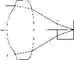
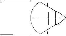
图1是本发明例1的衍射光学透镜的光路视图。Fig. 1 is a view of the optical path of the diffractive optical lens of Example 1 of the present invention.
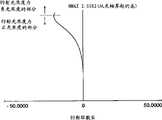
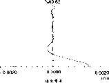
图2是本发明例1的衍射光学透镜对波长λ=635nm的球差的视图。Fig. 2 is a view of the spherical aberration to the wavelength λ = 635 nm of the diffractive optical lens of Example 1 of the present invention.
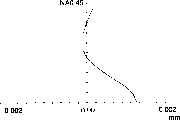
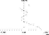
图3是本发明例1的衍射光学透镜对波长λ=780nm的NA=0.45以内的球差的视图。Fig. 3 is a view showing the spherical aberration within NA = 0.45 for the wavelength λ = 780 nm of the diffractive optical lens of Example 1 of the present invention.
图4是本发明例1的衍射光学透镜对波长λ=780nm的直到NA=0.60的球差的视图。Fig. 4 is a view of spherical aberration up to NA = 0.60 for the wavelength λ = 780 nm of the diffractive optical lens of Example 1 of the present invention.
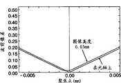
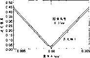
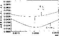
图5是本发明例1的衍射光学透镜对波长λ=635nm的波前象差的视图。Fig. 5 is a view of the wavefront aberration of the diffractive optical lens of Example 1 of the present invention to the wavelength λ = 635 nm.
图6是本发明例1的衍射光学透镜对波长λ=780nm的产生的波前象差的视图。Fig. 6 is a view showing the wavefront aberration generated by the diffractive optical lens of Example 1 of the present invention to the wavelength λ = 780nm.
图7是本发明例2的衍射光学透镜对波长λ=405nm的光路视图。Fig. 7 is a view of the optical path of the diffractive optical lens of Example 2 of the present invention to the wavelength λ = 405nm.
图8是本发明例2的衍射光学透镜对波长λ=635nm的光路视图。Fig. 8 is a view of the optical path of the diffractive optical lens of Example 2 of the present invention to the wavelength λ = 635nm.
图9是本发明例2的衍射光学透镜对波长λ=405nm的产生的球差的视图。Fig. 9 is a view showing the spherical aberration generated by the diffractive optical lens of Example 2 of the present invention to the wavelength λ = 405 nm.
图10是本发明例2的衍射光学透镜对波长λ=635nm的球差的视图。Fig. 10 is a view of the spherical aberration of the diffractive optical lens of Example 2 of the present invention to the wavelength λ = 635 nm.
图11是本发明例2的衍射光学透镜对波长λ=405nm的波前象差的视图。Fig. 11 is a view of the wavefront aberration of the diffractive optical lens of Example 2 of the present invention to the wavelength λ = 405 nm.
图12是本发明例2的衍射光学透镜对波长λ=635nm的波前象差的视图。Fig. 12 is a view of the wavefront aberration of the diffractive optical lens of Example 2 of the present invention to the wavelength λ = 635 nm.
图13是本发明例3的衍射光学透镜对波长λ=405nm的光路视图。Fig. 13 is a view of the optical path of the diffractive optical lens of Example 3 of the present invention for wavelength λ = 405nm.
图14是本发明例3的衍射光学透镜对波长λ=635nm的光路视图。Fig. 14 is a view of the optical path of the diffractive optical lens of Example 3 of the present invention to the wavelength λ=635nm.
图15是本发明例3的衍射光学透镜对波长λ=405nm的球差的视图。Fig. 15 is a view of the spherical aberration to the wavelength λ = 405 nm of the diffractive optical lens of Example 3 of the present invention.
图16是本发明例3的衍射光学透镜对波长λ=635nm的球差的视图。Fig. 16 is a view of the spherical aberration of the diffractive optical lens of Example 3 of the present invention to the wavelength λ = 635 nm.
图17是本发明例3的衍射光学透镜对波长λ=405nm的波前象差的视图。Fig. 17 is a view of the wavefront aberration of the diffractive optical lens of Example 3 of the present invention to the wavelength λ = 405 nm.
图18是本发明例3的衍射光学透镜对波长λ=635nm的波前象差的视图。Fig. 18 is a view of the wavefront aberration of the diffractive optical lens of Example 3 of the present invention to the wavelength λ = 635 nm.
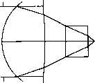
图19是本发明例4的衍射光学透镜的光路视图。Fig. 19 is a view of the optical path of the diffractive optical lens of Example 4 of the present invention.
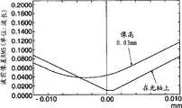
图20是本发明例4的衍射光学透镜对波长λ=635nm、650nm和780nm的球差的视图。Fig. 20 is a view of spherical aberration for wavelengths λ = 635nm, 650nm and 780nm by the diffractive optical lens of Example 4 of the present invention.
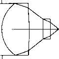
图21是本发明例5的衍射光学透镜的光路视图。Fig. 21 is a view of the optical path of the diffractive optical lens of Example 5 of the present invention.
图22是本发明例5的衍射光学透镜对波长λ=635nm、650nm和780nm的球差的视图。Fig. 22 is a view of spherical aberration for wavelengths λ = 635nm, 650nm and 780nm by the diffractive optical lens of Example 5 of the present invention.
图23是本发明例6的衍射光学透镜对波长λ=650nm的光路视图。Fig. 23 is a view of the optical path of the diffractive optical lens of Example 6 of the present invention to the wavelength λ=650nm.
图24是本发明例6的衍射光学透镜对波长λ=780nm(NA=0.5)的球差的视图。Fig. 24 is a view of the spherical aberration to the wavelength λ = 780 nm (NA = 0.5) of the diffractive optical lens of Example 6 of the present invention.
图25是本发明例6的衍射光学透镜对波长λ=650±10nm的直到数值孔径0.60的球差的视图。Fig. 25 is a view of spherical aberration up to numerical aperture 0.60 for the wavelength λ = 650 ± 10 nm by the diffractive optical lens of Example 6 of the present invention.
图26是本发明例6的衍射光学透镜对波长λ=780±10nm的直到数值孔径0.50的球差的视图。Fig. 26 is a view of the spherical aberration up to numerical aperture 0.50 for the wavelength λ = 780 ± 10 nm by the diffractive optical lens of Example 6 of the present invention.
图27是本发明例6的衍射光学透镜对波长λ=780nm的直到数值孔径0.60的球差的视图。Fig. 27 is a view of the spherical aberration up to the numerical aperture 0.60 for the wavelength λ = 780 nm of the diffractive optical lens of Example 6 of the present invention.
图28是本发明例6的衍射光学透镜对波长λ=650nm的波前象差rms的视图。Fig. 28 is a view of the wavefront aberration rms to the wavelength λ = 650 nm of the diffractive optical lens of Example 6 of the present invention.
图29是本发明例6的衍射光学透镜对波长λ=7800nm的波前象差rms的视图。Fig. 29 is a view of the wavefront aberration rms for the wavelength λ = 7800 nm of the diffractive optical lens of Example 6 of the present invention.
图30是本发明例7的衍射光学透镜对波长λ=650nm的波长的光路的视图。Fig. 30 is a view of the optical path of the diffractive optical lens of Example 7 of the present invention to a wavelength of wavelength λ = 650 nm.
图31是本发明例7的衍射光学透镜对λ=780nm(NA=0.5)的波长的光路视图。Fig. 31 is a view of the optical path of the diffractive optical lens of Example 7 of the present invention to the wavelength of λ = 780nm (NA = 0.5).
图32是本发明例7的衍射光学透镜对λ=650±10nm的波长的直到数值孔径0.60的球差的视图。Fig. 32 is a view of the spherical aberration up to numerical aperture 0.60 for the wavelength of λ = 650 ± 10 nm by the diffractive optical lens of Example 7 of the present invention.
图33是本发明例7的衍射光学透镜对λ=780±10nm的波长的直到数值孔径0.50的球差的视图。Fig. 33 is a view of the spherical aberration up to numerical aperture 0.50 for the wavelength of λ = 780 ± 10 nm of the diffractive optical lens of Example 7 of the present invention.
图34是本发明例7的衍射光学透镜对λ=780nm的波长的直到数值孔径0.60的球差的视图。Fig. 34 is a view of the spherical aberration up to numerical aperture 0.60 for the wavelength λ = 780 nm of the diffractive optical lens of Example 7 of the present invention.
图35是本发明例7的衍射光学透镜对λ=650nm的波长的波前象差rms的视图。Fig. 35 is a view of the wavefront aberration rms of the diffractive optical lens of Example 7 of the present invention to a wavelength of λ = 650 nm.
图36是本发明例7的衍射光学透镜对λ=780nm的波长的波前象差rms的视图。Fig. 36 is a view of the wavefront aberration rms of the diffractive optical lens of Example 7 of the present invention to a wavelength of λ = 780 nm.
图37是本发明例8的衍射光学透镜对λ=650nm的波长的光路的视图。Fig. 37 is a view of the optical path of the diffractive optical lens of Example 8 of the present invention to a wavelength of λ = 650 nm.
图38是本发明例8的衍射光学透镜对λ=780nm(NA=0.5)的波长的光路视图。Fig. 38 is a view of the optical path of the diffractive optical lens of Example 8 of the present invention to the wavelength of λ = 780nm (NA = 0.5).
图39是本发明例8的衍射光学透镜对λ=650±10nm的波长的直到数值孔径0.60的球差的视图。Fig. 39 is a view of the spherical aberration up to numerical aperture 0.60 for the wavelength λ = 650 ± 10 nm of the diffractive optical lens of Example 8 of the present invention.
图40是本发明例8的衍射光学透镜对λ=780±10nm的波长的直到数值孔径0.50的球差的视图。Fig. 40 is a view of the spherical aberration up to numerical aperture 0.50 for the wavelength of λ = 780 ± 10 nm of the diffractive optical lens of Example 8 of the present invention.
图41是本发明例8的衍射光学透镜对λ=780nm的波长的直到数值孔径0.60的球差的视图。Fig. 41 is a view of the spherical aberration up to numerical aperture 0.60 for the wavelength λ = 780 nm of the diffractive optical lens of Example 8 of the present invention.
图42是本发明例8的衍射光学透镜对λ=650nm的波长的波前象差rms的视图。Fig. 42 is a view of the wavefront aberration rms of the diffractive optical lens of Example 8 of the present invention to a wavelength of λ = 650 nm.
图43是本发明例8的衍射光学透镜对λ=780nm的波长的波前象差rms的视图。Fig. 43 is a view of the wavefront aberration rms of the diffractive optical lens of Example 8 of the present invention to a wavelength of λ = 780 nm.
图44是表示衍射环带数目与距本发明例6中的衍射光学透镜的光轴的高度之间的关系曲线。Fig. 44 is a graph showing the relationship between the number of diffractive annular zones and the height from the optical axis of the diffractive optical lens in Example 6 of the present invention.
图45是表示衍射环带数目与距本发明例7中衍射光学透镜的光轴的高度之间的关系曲线。Fig. 45 is a graph showing the relationship between the number of diffractive annular zones and the height from the optical axis of the diffractive optical lens in Example 7 of the present invention.
图46是表示衍射环带数目与距本发明例8中衍射光学透镜的光轴的高度之间的关系曲线。Fig. 46 is a graph showing the relationship between the number of diffraction ring zones and the height from the optical axis of the diffractive optical lens in Example 8 of the present invention.
图47是典型地表示衍射透镜功率与根据本发明的示例的衍射光学透镜的透镜形状之间的关系的视图。FIG. 47 is a view typically showing the relationship between the power of a diffractive lens and the lens shape of a diffractive optical lens according to an example of the present invention.
图48是表示根据本发明的第二实施例的光学头装置的结构的光路图。Fig. 48 is an optical path diagram showing the structure of an optical pickup device according to a second embodiment of the present invention.
图49是表示根据本发明的第三实施例的光学头装置的结构的光路图。Fig. 49 is an optical path diagram showing the structure of an optical pickup device according to a third embodiment of the present invention.
图50是本发明例9的物镜对λ=650nm的波长的光路的视图。Fig. 50 is a view of the optical path of the objective lens of Example 9 of the present invention to a wavelength of λ = 650 nm.
图51是本发明例9的物镜对λ=780nm的波长的光路视图。Fig. 51 is a view of the optical path of the objective lens of Example 9 of the present invention to a wavelength of λ=780nm.
图52是本发明例9的物镜对λ=650nm的波长的球差的视图。Fig. 52 is a view of the spherical aberration of the objective lens of Example 9 of the present invention to a wavelength of λ = 650 nm.
图53是本发明例9的物镜对λ=780nm的波长的直到NA=0.45的球差的视图。Fig. 53 is a view of spherical aberration up to NA = 0.45 for the objective lens of Example 9 of the present invention to a wavelength of λ = 780 nm.
图54是本发明例9的物镜对λ=780nm的波长的直到NA=0.60的球差的视图。Fig. 54 is a view of spherical aberration up to NA = 0.60 for the objective lens of Example 9 of the present invention to a wavelength of λ = 780 nm.
图55是本发明例9的物镜对λ=650nm的波长的波前象差视图。Fig. 55 is a view of the wavefront aberration of the objective lens of Example 9 of the present invention to a wavelength of λ = 650 nm.
图56是本发明例9的物镜对λ=780nm的波长的波前象差视图。Fig. 56 is a view of the wavefront aberration of the objective lens of Example 9 of the present invention to a wavelength of λ = 780 nm.
图57是本发明例10的物镜对λ=650nm的波长的光路的视图。Fig. 57 is a view of the optical path of the objective lens of Example 10 of the present invention to a wavelength of λ = 650 nm.
图58是本发明的例10的物镜对λ=400nm的波长的光路的视图。Fig. 58 is a view of the optical path of the objective lens of Example 10 of the present invention to a wavelength of λ = 400 nm.
图59是本发明的例10的物镜对λ=780nm的波长的光路的视图。Fig. 59 is a view of the optical path of the objective lens of Example 10 of the present invention to a wavelength of λ = 780 nm.
图60是本发明的例10的物镜对λ=650nm的波长的球差的视图。Fig. 60 is a view of the spherical aberration of the objective lens of Example 10 of the present invention to a wavelength of λ = 650 nm.
图61是本发明的例10的物镜对λ=400nm的波长的球差的视图。Fig. 61 is a view of the spherical aberration of the objective lens of Example 10 of the present invention to a wavelength of λ = 400 nm.
图62是本发明的例10的物镜对λ=780的波长的直到NA=0.45的球差视图。Fig. 62 is a view of spherical aberration up to NA = 0.45 for the objective lens of Example 10 of the present invention to a wavelength of λ = 780.
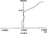
图63是本发明的例10的物镜对λ=780的波长的直到NA=0.65的球差视图。Fig. 63 is a view of spherical aberration up to NA = 0.65 for the objective lens of Example 10 of the present invention to a wavelength of λ = 780.
图64是本发明的例10的物镜对λ=650nm的波长的波前象差视图。Fig. 64 is a view of the wavefront aberration of the objective lens of Example 10 of the present invention to a wavelength of λ = 650 nm.
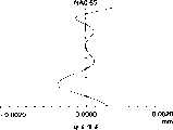
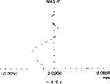
图65是本发明的例10的物镜对λ=400nm的波长的波前象差视图。Fig. 65 is a view of the wavefront aberration of the objective lens of Example 10 of the present invention to a wavelength of λ = 400 nm.
图66是本发明的例10的物镜对λ=780nm的波长的波前象差视图。Fig. 66 is a view of the wavefront aberration of the objective lens of Example 10 of the present invention to a wavelength of λ = 780 nm.
图67是表示根据本发明的实施例4的光学头装置的结构的视图。Fig. 67 is a view showing the structure of an optical pickup device according to
图68是本发明的例11的物镜对λ=650nm的波长的光路的视图。Fig. 68 is a view of the optical path of the objective lens of Example 11 of the present invention to a wavelength of λ = 650 nm.
图69是本发明的例11的物镜对λ=400nm的波长的光路视图。Fig. 69 is a view of the optical path of the objective lens of Example 11 of the present invention to a wavelength of λ = 400 nm.
图70是本发明的例11的物镜对λ=780nm的波长的光路视图。Fig. 70 is a view of the optical path of the objective lens of Example 11 of the present invention to a wavelength of λ = 780 nm.
图71是本发明的例11的物镜对λ=650nm的波长的球差的视图。Fig. 71 is a view of the spherical aberration of the objective lens of Example 11 of the present invention to a wavelength of λ = 650 nm.
图72是本发明的例11的物镜对λ=400nm的波长的球差的视图。Fig. 72 is a view of the spherical aberration of the objective lens of Example 11 of the present invention to a wavelength of λ = 400 nm.
图73是本发明的例11的物镜对λ=780nm的波长的直到数值孔径0.45的球差的视图。Fig. 73 is a view of the spherical aberration up to numerical aperture 0.45 for the wavelength λ = 780 nm of the objective lens of Example 11 of the present invention.
图74是本发明的例11的物镜对λ=780nm的波长的直到数值孔径0.65的球差的视图。Fig. 74 is a view of the spherical aberration up to numerical aperture 0.65 for the wavelength λ = 780 nm of the objective lens of Example 11 of the present invention.
图75是本发明的例11的物镜对λ=650nm的波长的波前象差视图。Fig. 75 is a view of the wavefront aberration of the objective lens of Example 11 of the present invention to a wavelength of λ = 650 nm.
图76是本发明的例11的物镜对λ=400nm的波长的波前象差视图。Fig. 76 is a view of the wavefront aberration of the objective lens of Example 11 of the present invention to a wavelength of λ = 400 nm.
图77是本发明的例11的物镜对λ=780nm的波长的波前象差视图。Fig. 77 is a view of the wavefront aberration of the objective lens of Example 11 of the present invention to a wavelength of λ = 780 nm.
图78是本发明的例12的物镜对λ=650nm的波长的光路的视图。Fig. 78 is a view of the optical path of the objective lens of Example 12 of the present invention to a wavelength of λ = 650 nm.
图79是本发明的例12的物镜对λ=400nm的波长的光路视图。Fig. 79 is a view of the optical path of the objective lens of Example 12 of the present invention to a wavelength of λ = 400 nm.
图80是本发明的例12的物镜对λ=780nm的波长的光路视图。Fig. 80 is a view of the optical path of the objective lens of Example 12 of the present invention to a wavelength of λ = 780 nm.
图81是本发明的例12的物镜对λ=650nm的波长的球差的视图。Fig. 81 is a view of the spherical aberration of the objective lens of Example 12 of the present invention to a wavelength of λ = 650 nm.
图82是本发明的例12的物镜对λ=400nm的波长的球差的视图。Fig. 82 is a view of the spherical aberration of the objective lens of Example 12 of the present invention to a wavelength of λ = 400 nm.
图83是本发明的例12的物镜对λ=780nm的波长的直到数值孔径0.45的球差的视图。Fig. 83 is a view of the spherical aberration up to numerical aperture 0.45 for the wavelength λ = 780 nm of the objective lens of Example 12 of the present invention.
图84是本发明的例12的物镜对λ=780nm的波长的直到数值孔径0.65的球差的视图。Fig. 84 is a view of the spherical aberration up to numerical aperture 0.65 for the wavelength λ = 780 nm of the objective lens of Example 12 of the present invention.
图85是本发明的例12的物镜对λ=650nm的波长的波前象差视图。Fig. 85 is a view of the wavefront aberration of the objective lens of Example 12 of the present invention to a wavelength of λ = 650 nm.
图86是本发明的例12的物镜对λ=400nm的波长的波前象差视图。Fig. 86 is a view of the wavefront aberration of the objective lens of Example 12 of the present invention to a wavelength of λ = 400 nm.
图87是本发明的例12的物镜对λ=780nm的波长的波前象差视图。Fig. 87 is a view of the wavefront aberration of the objective lens of Example 12 of the present invention to a wavelength of λ = 780 nm.
图88是本发明的例13的物镜对λ=650nm的波长的光路的视图。Fig. 88 is a view of the optical path of the objective lens of Example 13 of the present invention to a wavelength of λ = 650 nm.
图89是本发明的例13的物镜对λ=400nm的波长的光路视图。Fig. 89 is a view of the optical path of the objective lens of Example 13 of the present invention to a wavelength of λ = 400 nm.
图90是本发明的例13的物镜对λ=780nm的波长的光路视图。Fig. 90 is a view of the optical path of the objective lens of Example 13 of the present invention to a wavelength of λ = 780nm.
图91是本发明的例13的物镜对λ=650nm的波长的球差的视图。Fig. 91 is a view of the spherical aberration of the objective lens of Example 13 of the present invention to a wavelength of λ = 650 nm.
图92是本发明的例13的物镜对λ=400nm的波长的球差的视图。Fig. 92 is a view of the spherical aberration of the objective lens of Example 13 of the present invention to a wavelength of λ = 400 nm.
图93是本发明的例13的物镜对λ=780nm的波长的直到数值孔径0.45的球差视图。Fig. 93 is a view of spherical aberration up to numerical aperture 0.45 for the wavelength λ = 780 nm of the objective lens of Example 13 of the present invention.
图94是本发明的例12的物镜对λ=780nm的波长的直到数值孔径0.65的球差视图。Fig. 94 is a view of spherical aberration up to a numerical aperture of 0.65 for the objective lens of Example 12 of the present invention to a wavelength of λ = 780 nm.
图95是本发明的例13的物镜对λ=650nm的波长的波前象差视图。Fig. 95 is a view of the wavefront aberration of the objective lens of Example 13 of the present invention to a wavelength of λ = 650 nm.
图96是本发明的例13的物镜对λ=400nm的波长的波前象差视图。Fig. 96 is a view of the wavefront aberration of the objective lens of Example 13 of the present invention to a wavelength of λ = 400 nm.
图97是本发明的例13的物镜对λ=780nm的波长的波前象差视图。Fig. 97 is a view of the wavefront aberration of the objective lens of Example 13 of the present invention to a wavelength of λ = 780 nm.
图98是本发明的例13的物镜对λ=400nm的波长的光路图。Fig. 98 is an optical path diagram of the objective lens of Example 13 of the present invention to a wavelength of λ=400nm.
图99是本发明的例13的物镜对波长λ=400nm±10nm的球差视图。Fig. 99 is a spherical aberration view of the objective lens of Example 13 of the present invention to wavelength λ = 400nm ± 10nm.
图100是本发明的例13的物镜对波长λ=650nm±10nm的球差视图。Fig. 100 is a spherical aberration view of the objective lens of Example 13 of the present invention to wavelength λ = 650nm ± 10nm.
图101是本发明的例13的物镜对波长λ=780nm±10nm的球差视图。Fig. 101 is a spherical aberration view of the objective lens of Example 13 of the present invention to wavelength λ = 780nm ± 10nm.
图102是表示根据本发明实施例8的光学头装置第一结构的光路视图。Fig. 102 is an optical path view showing the first structure of the optical pickup device according to Embodiment 8 of the present invention.
图103是表示根据本发明实施例8的光学头装置第二结构的光路视图。Fig. 103 is an optical path view showing the second structure of the optical pickup device according to Embodiment 8 of the present invention.
图104是表示根据本发明实施例8的光学头装置第三结构的光路视图。Fig. 104 is an optical path view showing a third structure of an optical pickup device according to Embodiment 8 of the present invention.
图105是表示根据本发明实施例8的光学头装置第四结构的光路视图。Fig. 105 is an optical path view showing a fourth structure of an optical pickup device according to Embodiment 8 of the present invention.
图106是表示根据本发明实施例8的光学头装置第五结构的光路视图。Fig. 106 is an optical path view showing a fifth structure of an optical pickup device according to Embodiment 8 of the present invention.
图107是表示根据本发明实施例8的光学头装置第六结构的光路视图。Fig. 107 is an optical path view showing a sixth structure of an optical pickup device according to Embodiment 8 of the present invention.
图108是表示根据本发明实施例8的光学头装置第七结构的光路视图。Fig. 108 is an optical path view showing a seventh structure of an optical pickup device according to Embodiment 8 of the present invention.
图109是Super RENS系统的光盘结构的典型视图。Figure 109 is a typical view of the optical disc structure of the Super RENS system.
图110是表示成像放大率m2与根据本发明的实施例8的例15的物镜的波前象差之间关系的曲线。Fig. 110 is a graph showing the relationship between the imaging magnification m2 and the wavefront aberration of the objective lens of Example 15 according to Embodiment 8 of the present invention.
图111是根据本发明的实施例8的例15的截面图。Fig. 111 is a sectional view of Example 15 of Embodiment 8 according to the present invention.
图112是例15的球差视图。Figure 112 is a spherical aberration view of Example 15.
图113是衍射图案作用的示图。Figure 113 is an illustration of the effect of a diffraction pattern.
图114是表示色差对根据本发明的实施例8的物镜的球差的影响的典型视图。Fig. 114 is a typical view showing the influence of chromatic aberration on the spherical aberration of the objective lens according to Embodiment 8 of the present invention.
图115是表示正一阶衍射对根据本发明的实施例8的物镜的球差的影响的典型视图。Fig. 115 is a typical view showing the influence of positive first-order diffraction on the spherical aberration of the objective lens according to Embodiment 8 of the present invention.
图116是表示负一阶衍射对根据本发明的实施例8的物镜的球差的影响的典型视图。Fig. 116 is a typical view showing the influence of negative first-order diffraction on the spherical aberration of the objective lens according to Embodiment 8 of the present invention.
图117是表示根据本发明的实施例7的光学头装置的结构的光路图。Fig. 117 is an optical path diagram showing the configuration of an optical pickup device according to Embodiment 7 of the present invention.
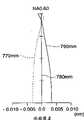
图118是作为根据本发明的实施例7的例15的物镜的衍射光学透镜(具有衍射面的物镜)的光路图。118 is an optical path diagram of a diffractive optical lens (objective lens having a diffractive surface) as an objective lens of Example 15 according to Embodiment 7 of the present invention.
图119是图118中的衍射光学透镜对于波长(λ)=640、650、660nm的直到数值孔径0.60的球差视图。Fig. 119 is a view of spherical aberration up to numerical aperture 0.60 for the diffractive optical lens in Fig. 118 for wavelengths (λ) = 640, 650, 660 nm.
图120是在例15中在光信息媒体的透明衬底厚度大于图118中的时衍射光学透镜的光路图。FIG. 120 is an optical path diagram of the diffractive optical lens when the thickness of the transparent substrate of the optical information medium is larger than that in FIG. 118 in Example 15. FIG.
图121是图120中的衍射光学透镜对于波长λ=770、780、790nm的直到数值孔径0.60的球差视图。Fig. 121 is a view of spherical aberration up to numerical aperture 0.60 of the diffractive optical lens in Fig. 120 for wavelengths λ = 770, 780, 790 nm.
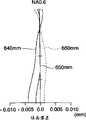
图122作为根据本发明的实施例7的例16的物镜的衍射光学透镜(具有衍射面的物镜)的光路图。Fig. 122 is an optical path diagram of a diffractive optical lens (objective lens having a diffractive surface) as an objective lens of Example 16 according to Embodiment 7 of the present invention.
图123是图122中的衍射光学透镜对于波长(λ)=640、650、660nm的直到数值孔径0.60的球差视图。Fig. 123 is a view of spherical aberration up to numerical aperture 0.60 for the diffractive optical lens in Fig. 122 for wavelengths (λ) = 640, 650, 660 nm.
图124是在例16中在光信息媒体的透明衬底厚度大于图122中的时衍射光学透镜的光路图。Fig. 124 is an optical path diagram of the diffractive optical lens when the thickness of the transparent substrate of the optical information medium is larger than that in Fig. 122 in Example 16.
图125是图124中的衍射光学透镜对于波长λ=770、780、790nm的直到数值孔径0.60的球差视图。Fig. 125 is a view of spherical aberration up to numerical aperture 0.60 of the diffractive optical lens in Fig. 124 for wavelengths λ = 770, 780, 790 nm.
图126作为根据本发明的实施例7的例17的物镜的衍射光学透镜(具有衍射面的物镜)的光路图。Fig. 126 is an optical path diagram of a diffractive optical lens (objective lens having a diffractive surface) as an objective lens of Example 17 according to Embodiment 7 of the present invention.
图127是图126中的衍射光学透镜对于波长(λ)=640、650、660nm的直到数值孔径0.60的球差视图。Fig. 127 is a view of spherical aberration up to numerical aperture 0.60 for the diffractive optical lens in Fig. 126 for wavelengths (λ) = 640, 650, 660 nm.
图128是在例17中在光信息媒体的透明衬底厚度大于图126中的时衍射光学透镜的光路图。FIG. 128 is an optical path diagram of the diffractive optical lens when the thickness of the transparent substrate of the optical information medium is larger than that in FIG. 126 in Example 17. FIG.
图129是图128中的衍射光学透镜对于波长(λ)=770、780、790nm的直到数值孔径0.60的球差视图。Fig. 129 is a view of spherical aberration up to numerical aperture 0.60 for the diffractive optical lens in Fig. 128 for wavelengths (λ) = 770, 780, 790 nm.
图130是作为根据本发明的实施例7的例18的物镜的衍射光学透镜(具有衍射面的物镜)的光路图。130 is an optical path diagram of a diffractive optical lens (objective lens having a diffractive surface) as an objective lens of Example 18 of Embodiment 7 according to the present invention.
图131是图130中的衍射光学透镜对于波长(λ)=390、400、410nm的直到数值孔径0.70的球差视图。Fig. 131 is a view of spherical aberration up to numerical aperture 0.70 for the diffractive optical lens in Fig. 130 for wavelengths (λ) = 390, 400, 410 nm.
图132是在例18中在光信息媒体的透明衬底厚度大于图130中的时衍射光学透镜的光路图。FIG. 132 is an optical path diagram of the diffractive optical lens when the thickness of the transparent substrate of the optical information medium is larger than that in FIG. 130 in Example 18. FIG.
图133是图132中的衍射光学透镜对于波长λ=640、650、660nm的直到数值孔径0.70的球差视图。Fig. 133 is a spherical aberration view of the diffractive optical lens in Fig. 132 for wavelengths λ = 640, 650, 660 nm up to numerical aperture 0.70.
图134是衍射环带的横截面视图。Figure 134 is a cross-sectional view of a diffractive annulus.
用于再现来自光信息记录媒体的信息或把信息记录在光信息记录媒体上的光学头装置具有用于发出具有第一波长的第一光通量的第一光源;用于发出具有第二波长的第二光通量的第二光源,第一波长不同于第二波长;具有光轴和衍射部分的会聚光学系统以及光检测器。另外,衍射部分在通过衍射部分的第一光通量中产生比其它阶衍射光线更加多的n阶衍射光线,并且在也通过衍射部分的第二光通量中产生比其它阶衍射光线更加多的n阶衍射光线,n代表非零整数。本发明的光学元件是一种具有能够实现前述实施例的衍射部分的元件。用于再现来自光信息记录媒体的信息或把信息记录在光信息记录媒体上的装置具有上述的光学头装置。For reproducing information from an optical information recording medium or recording information on an optical head device having a first light source for emitting a first luminous flux with a first wavelength; for emitting a first light flux with a second wavelength A second light source of two luminous fluxes, the first wavelength being different from the second wavelength; a converging optical system having an optical axis and a diffractive part; and a photodetector. In addition, the diffractive portion generates more n-order diffracted rays than other-order diffracted rays in the first luminous flux passing through the diffractive portion, and generates more n-order diffracted rays than other-order diffracted rays in the second luminous flux that also passes through the diffracted portion Rays, where n represents a non-zero integer. The optical element of the present invention is an element having a diffractive portion capable of realizing the aforementioned embodiments. An apparatus for reproducing information from an optical information recording medium or recording information on an optical information recording medium has the above-mentioned optical head apparatus.
顺便提出,“n阶衍射光线的量大于任何其它阶衍射光线的量”意味着对于n阶衍射光线的衍射效率高于n阶衍射光线之外的其它阶衍射光线。另外,n阶中的n还包括符号,当已经通过衍射部分的第一光通量中产生的正一阶衍射光线多于其它阶衍射光线时,意思是产生的正一阶衍射光线多于其它阶衍射光线,即使是在通过衍射部分的第二光通量中,它不包括已经通过衍射部分的第二光通量中产生的负一阶衍射光线多于其它阶衍射光线的含义。Incidentally, "the amount of n-order diffracted rays is greater than that of any other order diffracted rays" means that the diffraction efficiency for n-order diffracted rays is higher than other-order diffracted rays other than n-order diffracted rays. In addition, n in the nth order also includes a sign, when the positive first-order diffracted rays generated in the first luminous flux that has passed through the diffractive part are more than the other-order diffracted rays, it means that the positive first-order diffracted rays are more than the other-order diffracted rays Light, even in the second luminous flux passing through the diffractive part, does not include the meaning that the negative first-order diffracted rays generated in the second luminous flux that has passed through the diffractive part are more than other diffracted rays.
本发明的光学头装置是一种其中一个光学头装置可对使用至少两个彼此不相同的波长的不同类型的光信息记录媒体进行记录和/或再现的装置。即,本发明的光学头装置是一种用来记录/再现不同信息记录媒体如第一光信息记录媒体和第二光信息记录媒体的装置。光学头装置的第一光源发出第一光通量来从第一光信息记录媒体再现信息或把信息记录在第一光信息记录媒体上,而光学头装置的第二光源发出第二光通量来从第二光信息记录媒体再现信息或把信息记录在第二光信息记录媒体上。通常,光信息记录媒体在信息记录面上具有透明衬底。The optical head device of the present invention is a device in which one optical head device can record and/or reproduce different types of optical information recording media using at least two wavelengths different from each other. That is, the optical head device of the present invention is a device for recording/reproducing different information recording media such as a first optical information recording medium and a second optical information recording medium. The first light source of the optical head device emits the first luminous flux to reproduce information from the first optical information recording medium or information is recorded on the first optical information recording medium, and the second light source of the optical head device emits the second luminous flux from the second optical information recording medium. The optical information recording medium reproduces information or records information on the second optical information recording medium. Generally, an optical information recording medium has a transparent substrate on an information recording surface.
当以另一种方式实现本发明的功能时,会聚光学系统能够通过第一透明衬底把到达衍射部分的第一光通量在衍射部分产生的“第一光通量的n阶衍射光线”会聚到第一光信息记录媒体的第一信息记录面上来再现记录在第一光信息记录媒体中的信息或者把信息记录在第一光信息记录媒体上,而且会聚光学系统能够通过第二透明衬底把到达衍射部分的第二光通量在衍射部分产生的“第二光通量的n阶衍射光线”会聚到第二光信息记录媒体的第二信息记录面上来再现记录在第二光信息记录媒体中的信息或者把信息记录在第二光信息记录媒体上,而且光检测器能够接收从第一信息记录面或第二信息记录面反射的光通量。When realizing the function of the present invention in another way, the converging optical system can converge the "n-order diffracted light of the first luminous flux" generated by the first luminous flux reaching the diffractive part to the first through the first transparent substrate. On the first information recording surface of the optical information recording medium, reproduce the information recorded in the first optical information recording medium or record the information on the first optical information recording medium, and the converging optical system can pass the arrival diffraction through the second transparent substrate Part of the second luminous flux produced in the diffractive part is converged to the second information recording surface of the second optical information recording medium to reproduce the information recorded in the second optical information recording medium or to transfer the information to the second optical information recording medium. Recorded on the second optical information recording medium, and the photodetector is capable of receiving light flux reflected from the first information recording surface or the second information recording surface.
下面将表示优选的实施例,其中会聚光学系统能够在物镜像侧上的第一光通量中第一光信息记录媒体的指定数值孔径范围内,波前象差不大于0.07λrms的状态下(换言之,在指定数值孔径范围内于最佳像点(最佳聚焦)光通量取衍射极限值或少些的情况下),把第一光通量中的n阶衍射光线会聚到第一光信息记录媒体的第一信息记录面上,并且,会聚光学系统能够在物镜像侧上的第二光通量中第二光信息记录媒体的指定数值孔径范围内波前象差不大于0.07λrms的状态下(换言之,在指定数值孔径范围内于最佳像点(最佳聚焦)光通量取衍射极限值或少些的情况下),把第二光通量中的n阶衍射光线会聚到第二光信息记录媒体的第二信息记录面上。A preferred embodiment will be represented below, wherein the converging optical system can be within the specified numerical aperture range of the first optical information recording medium in the first luminous flux on the objective mirror side, under the state where the wavefront aberration is not more than 0.07λrms (in other words, In the specified numerical aperture range at the best image point (best focus) luminous flux takes the diffraction limit value or less), the n-order diffracted rays in the first luminous flux are converged to the first of the first optical information recording medium On the information recording surface, and the converging optical system can be in the state where the wavefront aberration is not greater than 0.07λrms within the specified numerical aperture range of the second optical information recording medium in the second luminous flux on the objective mirror side (in other words, at the specified value In the best image point (best focus) luminous flux takes the diffraction limit value or less in the aperture range), the n-order diffracted rays in the second luminous flux are converged to the second information recording surface of the second optical information recording medium superior.
另外,优选地在物镜像侧上的指定数值孔径范围内,波前象差不大于0.07λrms的状态下,把n阶衍射光线会聚到各个信息记录面上,即使是在第一光源或第二光源中有由温度波动和电流波动引起的大约±10nm的波长漂移的情况下。特别优选地是n阶衍射光线在物镜像侧上的指定数值孔径范围内的0.07λrms或更小的波前象差的状态下被会聚,即使是在第一光通量或第二光通量是一个具有600nm或更小(例如350-480nm)的波长并且产生大约±10nm的波长漂移的时候。In addition, preferably within the specified numerical aperture range on the objective mirror side, under the condition that the wavefront aberration is not greater than 0.07λrms, the n-order diffracted rays are converged on each information recording surface, even if it is in the first light source or the second In the case of a wavelength drift of about ±10nm caused by temperature fluctuations and current fluctuations in the light source. It is particularly preferable that the nth-order diffracted rays are converged in a state of wavefront aberration of 0.07λrms or less within a specified numerical aperture range on the objective mirror side, even if the first luminous flux or the second luminous flux is one with 600 nm or smaller (eg, 350-480nm) wavelength and produce a wavelength shift of about ±10nm.
顺便提出,当n阶衍射光线是正一阶衍射光线或负一阶衍射光线时,光量的损失小于使用比±1阶更高阶的衍射光线的情况,这是优选的。Incidentally, when the nth-order diffracted rays are positive first-order diffracted rays or negative first-order diffracted rays, the loss of light quantity is smaller than the case of using diffracted rays higher than ±1 order, which is preferable.
另外,当衍射部分中第一光通量的n阶衍射光线的衍射效率以A%代表,并且其它的某阶衍射光线的衍射效率以B%代表时(优选地,最大衍射效率的阶数处于除n之外的数值中),优选地满足A-B≥10,而当衍射部分中的第二光通量的n阶衍射光线的衍射效率以A'%代表,并且其它的某阶衍射光线的衍射效率以B'%代表时,优选地满足A'-B'≥10。A-B≥30和A'-B'≥30是更优选的,A-B≥50和A'-B'≥50是更优选的,A-B≥70和A'-B'≥70进一步优选。In addition, when the diffraction efficiency of the n-order diffracted rays of the first luminous flux in the diffraction part is represented by A%, and the diffraction efficiency of other certain-order diffracted rays is represented by B% (preferably, the order of the maximum diffraction efficiency is in the division n Among other values), it is preferable to satisfy A-B≥10, and when the diffraction efficiency of the n-order diffracted light of the second luminous flux in the diffractive part is represented by A'%, and the diffraction efficiency of other certain-order diffracted light is represented by B' When represented by %, it is preferable to satisfy A'-B'≥10. A-B≥30 and A'-B'≥30 are more preferred, A-B≥50 and A'-B'≥50 are more preferred, A-B≥70 and A'-B'≥70 are further preferred.
当第一光通量和第二光通量均被用于向光信息记录媒体记录信息时,优选地衍射部分中的n阶衍射光线的衍射效率在第一光通量的波长和第二光通量的波长之间的波长处为最大值。When both the first luminous flux and the second luminous flux are used to record information to the optical information recording medium, it is preferable that the diffraction efficiency of the n-order diffracted rays in the diffracted part is at a wavelength between the wavelength of the first luminous flux and the wavelength of the second luminous flux at the maximum value.
当第一光通量和第二光通量之一被用于向光信息记录媒体记录信息并且另一光通量仅用于再现时,优选地衍射部分中的n阶衍射光线的衍射效率在第一光通量的波长和第二光通量的波长之间的波长处为最小值。更优选地衍射部分中的n阶衍射光线的衍射效率在用于信息记录的第一光通量的波长和第二光通量的波长处为最大值。When one of the first luminous flux and the second luminous flux is used to record information to the optical information recording medium and the other luminous flux is only used for reproducing, preferably the diffraction efficiency of the n-order diffracted light in the diffraction part is between the wavelength of the first luminous flux and The wavelength between the wavelengths of the second luminous flux has a minimum value. It is more preferable that the diffraction efficiency of the nth order diffracted light in the diffracted portion is maximum at the wavelength of the first light flux and the wavelength of the second light flux used for information recording.
作为提供有衍射部分的光学元件,给出了在会聚光学系统上设有折射面和平面型元件的透镜,但这里没有特定的限制。As an optical element provided with a diffractive portion, a lens provided with a refractive surface and a planar element on a converging optical system is given, but there is no particular limitation here.
当具有折射面的透镜作为提供有衍射部分的光学元件时,作为具体的光学元件的示例给出的是物镜、准直透镜和耦合透镜。在各个透镜上的折射面上,设有衍射部分。仅仅是意在提供衍射部分的平面状或透镜状光学元件也可被增加到会聚光学系统。When a lens having a refractive surface is used as an optical element provided with a diffractive portion, given as specific examples of the optical element are an objective lens, a collimator lens, and a coupling lens. On the refractive surface on each lens, a diffractive portion is provided. Planar or lenticular optical elements intended only to provide a diffractive portion may also be added to the converging optical system.
顺便提出,当在物镜的折射面上提供衍射部分时,优选地物镜的外径(如果有凸缘则外径包括凸缘)比光圈直径大0.4mm-2mm。Incidentally, when the diffractive portion is provided on the refractive surface of the objective lens, it is preferable that the outer diameter of the objective lens (the outer diameter including the flange if there is a flange) is 0.4 mm to 2 mm larger than the aperture diameter.
衍射部分可提供在光源侧的光学元件的光学表面上或者在像侧上(光信息记录媒体侧),或者在两侧上。另外,衍射部分可提供在凹面和凸面上。The diffractive portion may be provided on the optical surface of the optical element on the light source side or on the image side (optical information recording medium side), or on both sides. In addition, diffractive portions may be provided on both concave and convex surfaces.
当衍射部分提供在物镜上时,就更好,因为部件数目减少了,制造时组装光学头装置的误差减少了。在那种情况下,优选地物镜是单元件型,但是它也可以是双元件型。优选为塑料透镜,但是玻璃透镜也可接受。也可以把上面形成有衍射部分的树脂层设置在玻璃透镜的表面上。优选地其上设有衍射部分的物镜在其外部周边上设有具有沿垂直于光轴方向延伸的表面的凸缘部分。这使得它能容易地准确安装在光学头装置上,并且使得即使在周围环境温度波动时也可能获得稳定的性能。更加优选地是物镜的折射面是非球表面并且衍射部分提供在非球表面上。衍射部分当然可提供在物镜的任何一侧上或在其两侧上。When the diffractive portion is provided on the objective lens, it is better because the number of parts is reduced and errors in assembling the optical pickup device at the time of manufacture are reduced. In that case, it is preferable that the objective lens is of a single-element type, but it may also be of a dual-element type. Plastic lenses are preferred, but glass lenses are also acceptable. It is also possible to provide a resin layer on which the diffractive portion is formed on the surface of the glass lens. It is preferable that the objective lens on which the diffractive portion is provided is provided on its outer periphery with a flange portion having a surface extending in a direction perpendicular to the optical axis. This makes it easy to mount accurately on the optical pickup device, and makes it possible to obtain stable performance even when the ambient temperature fluctuates. It is more preferable that the refractive surface of the objective lens is an aspheric surface and that the diffraction portion is provided on the aspherical surface. Diffractive portions may of course be provided on either side of the objective lens or on both sides thereof.
另外,优选地其上设有衍射部分的光学元件由Abbe数vd不小于50且不大于100的材料制成。它也可由塑料或玻璃制成。顺便提到,在塑料透镜的情况中,优选地材料的折射率在1.4-1.75的范围内,并且1.48-1.6是更优选的,最好是1.5-1.56。In addition, it is preferable that the optical element on which the diffractive portion is provided is made of a material having an Abbe number vd of not less than 50 and not more than 100. It can also be made of plastic or glass. Incidentally, in the case of a plastic lens, it is preferable that the refractive index of the material is in the range of 1.4-1.75, and 1.48-1.6 is more preferable, most preferably 1.5-1.56.
当衍射部分设在透镜上时(优选在塑料透镜上),优选地满足下面的条件表达式,以获得对温度波动稳定的光学头装置和光学元件。When the diffractive portion is provided on a lens (preferably on a plastic lens), it is preferable to satisfy the following conditional expression in order to obtain an optical head device and an optical element that are stable against temperature fluctuations.
-0.0002/℃<Δn/ΔT<-0.00005/℃-0.0002/℃<Δn/ΔT<-0.00005/℃
其中,in,
ΔT是温度波动ΔT is the temperature fluctuation
Δn是透镜的折射率变化量。Δn is the amount of change in the refractive index of the lens.
优选满足下面的条件表达式。It is preferable to satisfy the following conditional expressions.
0.05nm/℃<Δλ1/ΔT<0.5nm/℃0.05nm/℃<Δλ1/ΔT<0.5nm/℃
其中,in,
Δλ1(nm)是第一光源的波长对于温度波动ΔT的变化量。Δλ1 (nm) is the change amount of the wavelength of the first light source with respect to the temperature fluctuation ΔT.
从光的使用效率方面看衍射部分优选是相位类型的,尽管它也可以是振幅类型。优选的衍射部分的衍射图案构形为相对于光轴对称旋转。优选的从光轴方向看衍射部分具有多个环形带,并且这些多个环形带大部分形成在其中心在光轴上或在光轴附近的同心圆上。圆形是优选的,但也可是椭圆。有台阶的火焰型环带衍射面尤其优选。还可以是形成有阶梯的环带衍射面。还可以是形成有阶梯作为随透镜远离光轴位置透镜厚度变大的方向上不连续移动的环形带的环带衍射面。顺便提到,优选地衍射部分是环带状,但也可是一维衍射栅。The diffractive portion is preferably of the phase type from the viewpoint of light use efficiency, although it may also be of the amplitude type. The diffraction pattern configuration of the preferred diffractive portion is symmetrically rotated with respect to the optical axis. It is preferable that the diffractive portion has a plurality of annular zones viewed from the direction of the optical axis, and most of these plurality of annular zones are formed on concentric circles whose centers are on or near the optical axis. A circle is preferred, but an ellipse is also possible. A stepped flame-shaped annulus diffractive surface is particularly preferred. It may also be an annular diffractive surface formed with steps. It may also be an annular zone diffraction surface formed with steps as annular zones that move discontinuously in a direction in which the thickness of the lens increases as the lens moves away from the optical axis. Incidentally, it is preferable that the diffractive portion is annular, but it may also be a one-dimensional diffraction grating.
当衍射部分表示环带状形式的同心圆时,衍射环状带的间距通过应用相位差函数或光路差函数来定义。在这种情况下,优选地在以表示多个环形带的位置的幂级数表示的相位差函数中除平方项之外的至少一项有一个非零系数。由于这种结构,可能校正由各自具有不同波长的光所引起的色差的球差。When the diffractive portion represents concentric circles in the form of annular bands, the pitch of the diffractive annular bands is defined by applying a phase difference function or an optical path difference function. In this case, it is preferable that at least one term other than the square term in the phase difference function expressed as a power series representing the positions of the plurality of annular zones has a non-zero coefficient. Due to this structure, it is possible to correct spherical aberration of chromatic aberration caused by lights each having a different wavelength.
当在以表示衍射部分的多个环形带的位置的幂级数表示的相位差函数中平方项有一个非零系数时,可校正修轴色差,这种情况是优选的。但是,重要的是当不把衍射环状带的间距作得很小时,也可能使以表示衍射部分的多个环形带的位置的幂级数表示的相位差函数中不包括平方项。When the square term has a non-zero coefficient in the phase difference function expressed as a power series representing the positions of the plurality of annular zones of the diffractive portion, axonometric chromatic aberration can be corrected, which is preferable. However, it is important that the square term is not included in the phase difference function expressed as a power series representing the positions of a plurality of annular zones of the diffractive portion unless the pitch of the diffractive annular zones is made very small.
顺便提到,优选地衍射部分的衍射环形带的台阶数在2到45范围内。更优选地是不超过40。进一步优选地是不大于15。顺便提到,台阶数的计数通过计算环状带的台阶部分的数目而得到。Incidentally, it is preferable that the number of steps of the diffraction annular zone of the diffraction portion is in the range of 2 to 45. More preferably not more than 40. It is further preferably not greater than 15. Incidentally, the count of the number of steps is obtained by counting the number of stepped portions of the endless belt.
另外,优选地光轴方向上衍射部分的衍射环形带的台阶部分的深度不大于2μm。由于这种结构,光学元件可简单制造,并且n阶衍射光线可容易地成为正一阶衍射光线或负一阶衍射光线。In addition, it is preferable that the depth of the step portion of the diffraction annular zone of the diffraction portion in the direction of the optical axis is not more than 2 μm. Due to this structure, the optical element can be manufactured simply, and the n-order diffracted rays can easily become positive first-order diffracted rays or negative first-order diffracted rays.
另外,当在光源侧光学元件的表面上设置衍射部分时,优选地台阶部分的深度随台阶部分离光轴越来越远而变得更大。In addition, when the diffractive portion is provided on the surface of the optical element on the light source side, it is preferable that the depth of the stepped portion becomes larger as the stepped portion becomes farther away from the optical axis.
关于衍射部分对光通量偏斜的效果,在本说明书中,光通量被偏斜向光轴方向的情况称为正效果,另一方面,光通量被偏斜而离开光轴方向的情况称为负效果。Regarding the effect of the diffractive part on the deflection of the luminous flux, in this specification, the situation in which the luminous flux is deflected to the direction of the optical axis is called a positive effect, and on the other hand, the situation in which the luminous flux is deflected away from the direction of the optical axis is called a negative effect.
关于环带状衍射表面上的间距,这里也提供一种间距,其中提供的间距反比于其离开光轴的高度。也可能提供一种具有非球面特性的间距,其中提供间距的方式与离开光轴的高度不成反比。With regard to the spacing on the ring-shaped diffractive surface, a spacing is also provided here, wherein the spacing provided is inversely proportional to its height from the optical axis. It is also possible to provide a pitch with aspheric properties, where the pitch is provided in such a way that it is not inversely proportional to the height from the optical axis.
尤其当提供具有非球面特性的间距时,即当所提供的间距不反比与离开光轴的高度时,优选地在光路差的函数中没有拐点,尽管也可能有拐点。Especially when providing a pitch with aspheric properties, ie when the provided pitch is not inversely proportional to the height from the optical axis, there is preferably no inflection point in the function of the optical path difference, although there may be an inflection point.
另外,增加到衍射部分中的衍射效果在衍射部分的整个表面上或者是正的或者是负的。也可能设置成使得增加到衍射部分中的衍射效果的加号或减号在垂直于光轴方向上更加远离光轴的方向上应至少被切换一阶。例如,给出一种类型,其中在垂直于光轴的方向上远离光轴的方向上符号从减号变为加号,如图47(c)所示。换言之,可以说衍射部分上刻制的多个环状带并且在靠近光轴的衍射环状带上,台阶部分被定位在远离光轴,而在远离光轴的衍射环状带上,台阶部分被定位在靠近光轴。还给出一种类型,其中在垂直于光轴的方向上远离光轴的方向上符号从加号变为减号,如图47(d)所示。换言之,可以说衍射部分上刻制的多个环状带,并且在靠近光轴的前述衍射环状带上,台阶部分被定位在靠近光轴,而在远离光轴的衍射环状带上,台阶部分被定位在远离光轴。In addition, the diffractive effect added to the diffractive portion is either positive or negative over the entire surface of the diffractive portion. It may also be provided that the plus or minus sign added to the diffractive effect in the diffractive part should be switched by at least one order in a direction perpendicular to the optical axis further away from the optical axis. For example, a type is given in which the sign changes from a minus sign to a plus sign in a direction away from the optical axis in a direction perpendicular to the optical axis, as shown in Fig. 47(c). In other words, it can be said that a plurality of annular bands are engraved on the diffractive portion and that on the diffractive annular band near the optical axis, the stepped portion is positioned away from the optical axis, and on the diffractive annular band far from the optical axis, the stepped portion are positioned close to the optical axis. A type is also given in which the sign changes from a plus sign to a minus sign in a direction perpendicular to the optical axis away from the optical axis, as shown in Fig. 47(d). In other words, it can be said that a plurality of annular bands are engraved on the diffractive portion, and on the aforementioned diffractive annular band near the optical axis, the step portion is positioned near the optical axis, and on the diffractive annular band far from the optical axis, The stepped portion is positioned away from the optical axis.
顺便提到,衍射环状带的间距(区段距离)意味着图134中在垂直于光轴的方向上环状带台阶与相邻的环状带台阶之间的距离p,而台阶深度的意思是图134中的光方向上的台阶的长度d。Incidentally, the pitch (section distance) of the diffractive annular zone means the distance p between the annular zone step and the adjacent annular zone step in the direction perpendicular to the optical axis in Fig. 134, while the step depth Means the length d of the step in the light direction in FIG. 134 .
顺便提到,当间距小时,上述部分上的会聚效果和发散效果变强,并且当间距变大时,上述部分上的会聚效果和发散效果变弱。Incidentally, when the pitch is small, the converging effect and the diverging effect on the above-mentioned parts become stronger, and when the pitch becomes large, the converging effect and the diverging effect on the above-mentioned parts become weak.
另外,衍射部分也可设在具有衍射部分的光学元件中的光通量所通过的整个表面部分上。换言之,也可以说也可以设置成使得物镜像侧最大数值孔径内的所有光通量可通过衍射部分。衍射部分也可简单设在光学元件的一个光表面的整个部分上或者使光学元件的一个光表面的不小于70%(优选为不小于80%,更好为不小于90%)的部分成为衍射部分。In addition, the diffractive portion may also be provided on the entire surface portion through which light flux passes in the optical element having the diffractive portion. In other words, it can also be said that it can also be set so that all light fluxes within the maximum numerical aperture on the mirror side of the objective can pass through the diffractive part. The diffractive portion also can be simply arranged on the whole part of an optical surface of the optical element or make not less than 70% (preferably not less than 80%, better not less than 90%) of an optical surface of the optical element become diffractive part.
另外,衍射部分可仅提供在光通量所通过的光学元件的一部分表面上,使另一区域成为光学元件中的折射表面或透射表面。当衍射部分仅提供在光通量所通过的表面的一部分上时,衍射部分可仅被提供在光轴附近包括光轴的部分上,或者衍射部分可仅设为环形形状而不设在光轴附近。例如,衍射部分可提供在光学元件的光表面中的10%或更多且在90%以下的表面上。或者使10%或更多并且小于50%的表面成为衍射部分。In addition, the diffractive portion may be provided only on a part of the surface of the optical element through which light flux passes, making the other area a refractive surface or a transmissive surface in the optical element. When the diffractive portion is provided only on a part of the surface through which the luminous flux passes, the diffractive portion may be provided only on a portion including the optical axis near the optical axis, or the diffractive portion may only be provided in a ring shape without being provided near the optical axis. For example, the diffractive portion may be provided on 10% or more and less than 90% of the surface of the optical surface of the optical element. Or make 10% or more and less than 50% of the surface a diffractive portion.
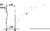
顺便提到,当仅在光通量所通过的光学元件的一部分表面上提供衍射部分时,在NA1>NA2的情况下NA1>NAH1、NAH1>NA2、NA2≥NAL1≥0是优选的。在NA2>NA1的情况下NA2>NAH2、NAH2>NA1、NA1≥NAL2≥0是优选的。顺便提出,当分别使用第一光通量和第二光通量时,NA1和NA2分别是物镜像侧的指定数值孔径。NAH1和NAH2的每一个是对于通过衍射部分最外侧的第一光通量和第二光通量的每一个的像侧上物镜的数值孔径。NAL1和NAL2的每一个是对于通过衍射部分最内侧的第一光通量和第二光通量的每一个的像侧上物镜的数值孔径。Incidentally, when the diffraction portion is provided only on a part of the surface of the optical element through which light flux passes, NA1>NAH1, NAH1>NA2, NA2≥NAL1≥0 are preferable in the case of NA1>NA2. In the case of NA2>NA1, NA2>NAH2, NAH2>NA1, NA1≥NAL2≥0 are preferable. Incidentally, when the first luminous flux and the second luminous flux are respectively used, NA1 and NA2 are designated numerical apertures on the mirror side of the objective, respectively. Each of NAH1 and NAH2 is the numerical aperture of the objective lens on the image side for each of the first luminous flux and the second luminous flux passing through the outermost sides of the diffractive portion. Each of NAL1 and NAL2 is a numerical aperture of the objective lens on the image side for each of the first light flux and the second light flux passing through the innermost side of the diffractive portion.
当衍射部分仅提供在光通量所经过的光学元件的一部分表面上时,在NA1>NA2的情况下,优选地第一光通量中在NA1或更小时通过衍射部分的光通量及在NA1或更小时通过除衍射部分之外的折射面的光被会聚在几乎相同的位置。在NA2>NA1的情况下,优选地第二光通量中在NA2或更小时通过衍射部分的光通量及在NA2或更小时通过除衍射部分之外的折射面的光被会聚在几乎相同的位置。When the diffractive portion is provided only on a part of the surface of the optical element through which the luminous flux passes, in the case of NA1>NA2, it is preferable that the luminous flux of the first luminous flux that passes through the diffractive portion at NA1 or less and the luminous flux that passes at NA1 or less except The light of the refractive surface other than the diffracted portion is collected at almost the same position. In the case of NA2>NA1, it is preferable that the light flux passing through the diffractive portion at NA2 or less and the light passing through a refractive surface other than the diffractive portion at NA2 or less of the second luminous flux be converged at almost the same position.
有一个其中衍射部分具有第一衍射图案和第二衍射图案的实施例,第二衍射图案比第一衍射图案离开光轴更远的距离。可以把衍射部分与在同一面上具有非衍射部分的折射表面组合起来。There is an embodiment in which the diffractive portion has a first diffractive pattern and a second diffractive pattern, the second diffractive pattern being at a greater distance from the optical axis than the first diffractive pattern. It is possible to combine diffractive portions with refractive surfaces having non-diffractive portions on the same face.
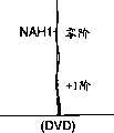
当使用两种类型的衍射图案时,也可设置成使得在通过衍射部分的第一衍射图案的第一光通量中,产生比其它阶衍射光线更多的n阶衍射光线,并能够将其会聚在第一信息记录面上,并且在通过衍射部分的第一衍射图案的第二光通量中,也产生比其它阶衍射光线更多的n阶衍射光线,并能够将其会聚在第二信息记录面上,在通过衍射部分的第二衍射图案的第一光通量中,产生比其它阶衍射光线更多的n阶衍射光线并能够将其会聚在第一信息记录面上,而在通过衍射部分的第二衍射图案的第二光通量中也产生比其它阶衍射光线更多的代表透射光的零阶光。这种情况的n阶优选是一阶。When using two types of diffraction patterns, it can also be arranged so that in the first luminous flux of the first diffraction pattern passing through the diffraction part, more n-order diffraction rays are generated than other order diffraction rays, and can be converged at On the first information recording surface, and in the second luminous flux of the first diffraction pattern passing through the diffractive part, more n-order diffracted rays than other orders of diffracted rays are also produced, and can be converged on the second information recording surface , in the first luminous flux of the second diffraction pattern passing through the diffractive part, more n-order diffracted rays are generated than other diffracted rays and can be converged on the first information recording surface, while the second diffracted rays passing through the diffractive part The second luminous flux of the diffraction pattern also generates more zero-order light representing transmitted light than other order diffracted rays. The nth order in this case is preferably the first order.
另外,在另一实施例中,在通过衍射部分的第一衍射图案的第一光通量中产生比其它阶衍射光线更多的n阶衍射光线并能够将其会聚在第一信息记录面上,并且在通过衍射部分的第一衍射图案的第二光通量中也产生比其它阶衍射光线更多的n阶衍射光线并能够将其会聚在第二信息记录面上,在通过衍射部分的第二衍射图案的第一光通量中产生比其它阶衍射光线更多的零阶衍射光线并能够将其会聚在第一信息记录面上,而在通过衍射部分的第二衍射图案的第二光通量中也产生比其它阶衍射光线更多的不是n阶的负数阶的衍射光线。这种情况的n阶优选是正一阶并且负数阶优选是负一阶。In addition, in another embodiment, more n-order diffracted rays than other-order diffracted rays are generated in the first luminous flux passing through the first diffraction pattern of the diffractive part and can be converged on the first information recording surface, and In the second luminous flux of the first diffraction pattern passing through the diffractive part, more n-order diffracted light rays than other order diffracted rays are also produced and can be converged on the second information recording surface. The first luminous flux of the first luminous flux produces more zero-order diffracted rays than other diffracted rays and can converge them on the first information recording surface, while the second luminous flux of the second diffraction pattern passing through the diffractive part also produces more zero-order diffracted rays than other diffracted rays. The diffracted rays of the first order are more than the diffracted rays of the negative order of the nth order. The nth order in this case is preferably the positive first order and the negative order is preferably the negative first order.
在用在各自具有不同厚度透明衬底的多个光信息记录媒体中的光学头装置或光学元件的情况下,尤其优选的是衍射部分的环形带的间距满足下面的条件表达式:In the case of an optical head device or an optical element used in a plurality of optical information recording media each having a different thickness transparent substrate, it is especially preferable that the spacing of the annular zone of the diffractive part satisfies the following conditional expression:
0.4<=|(Ph/Pf)-2|<=25 0.4<=|(Ph/Pf)-2|<=25
更优选的是0.8≤|(Ph/Pf)-2|≤6,并且最好是1.2≤|(Ph/Pf)-2|≤2。More preferably, 0.8≤|(Ph/Pf)-2|≤6, and most preferably 1.2≤|(Ph/Pf)-2|≤2.
相应于像侧上物镜的最大数值孔径的衍射部分的环形带的间距以Pf代表,并且相应于最大数值孔径1/2的衍射部分的环形带的间距以Ph代表。顺便提出,关于最大数值孔径,在光学头装置中进行信息读出/记录的一些类型的光信息记录媒体的指定数值孔径中最大的一个被认为是最大数值孔径。顺便提出,指定数值孔径意思是在其光学头装置中能使具有可能的指定波长的光通量向光信息记录媒体进行信息的读出/记录的一个数值孔径,但是也可以是某光信息记录媒体的标准所设定的数值孔径。另外,“相应于像侧上物镜的最大数值孔径的衍射部分的环形带的间距”意味着在最大数值孔径的情况下位于通过衍射部分的光通量的最外侧部分的环形带间距。“相应于最大数值孔径1/2的衍射部分的环形带的间距”意味着在数值孔径为最大数值孔径一半的情况下位于通过衍射部分的光通量的最外侧部分的环形带间距。The pitch of the annular zone of the diffractive portion corresponding to the maximum numerical aperture of the objective lens on the image side is represented by Pf, and the pitch of the annular zone of the diffractive portion corresponding to the maximum
顺便提出,也可接受一种光学头装置,其中对于分别来自两个光源的两个光通量中的一个光通量,使其在所指定的数值孔径内没有象差,并且对于指定的数值孔径之外的部分,使象差变成弥散斑。Incidentally, it is also acceptable to have an optical head device in which there is no aberration within a designated numerical aperture for one of the two light fluxes respectively from two light sources, and for light fluxes outside the designated numerical aperture part, making the aberration into a diffuse spot.
换言之,可有如下的说法。在使用第一光通量的情况下像侧上物镜的指定数值孔径内的第一光信息记录媒体的第一光通量在0.07λrms或更小的状态下被会聚到第一光信息记录媒体的第一信息记录面上,并且使得在使用第一光通量的情况下通过像侧物镜的指定数值孔径之外的第一光通量设成在第一信息记录面上大于0.07λrms,并把在使用第一光通量和通过前述数值孔径之外的第二光通量的情况下通过像侧物镜的指定数值孔径的第二光通量在0.07λrms或更小的状态下会聚到第二信息记录面上。在这种情况下,NA1小于NA2,并且,在记录和再现第一光信息记录媒体时使NA1与NA2之间的光通量弥散。In other words, it can be said as follows. In the case of using the first luminous flux, the first luminous flux of the first optical information recording medium within the designated numerical aperture of the objective lens on the image side is converged to the first information of the first optical information recording medium in a state of 0.07λrms or less on the recording surface, and make the first luminous flux outside the designated numerical aperture of the objective lens on the image side be set to be greater than 0.07λrms on the first information recording surface in the case of using the first luminous flux, and use the first luminous flux and pass through In the case of the second light flux other than the aforementioned numerical aperture, the second light flux passing through the specified numerical aperture of the image side objective lens converges on the second information recording surface in a state of 0.07λrms or less. In this case, NA1 is smaller than NA2, and the light flux between NA1 and NA2 is diffused when recording and reproducing the first optical information recording medium.
或者,在使用第二光通量的情况下像侧上物镜的指定数值孔径内的第二光信息记录媒体的第二光通量在0.07λrms或更小的状态下被会聚到第二光信息记录媒体的第二信息记录面上,并且使得在使用第二光通量的情况下通过像侧物镜的指定数值孔径之外的第二光通量在第二信息记录面上变成大于0.07λrms,并把在使用第二光通量和通过前述数值孔径之外的第一光通量的情况下通过像侧物镜的指定数值孔径的第一光通量在0.07λrms或更小的状态下会聚到第一信息记录面上。在这种情况下,NA1大于NA2,并且,在记录和再现第二光信息记录媒体时使NA2与NA1之间的光通量弥散。Or, in the case of using the second luminous flux, the second luminous flux of the second optical information recording medium within the specified numerical aperture of the objective lens on the image side is converged to the second optical information recording medium in a state of 0.07λrms or less. On the second information recording surface, and make the second luminous flux beyond the designated numerical aperture of the image side objective lens become greater than 0.07λrms on the second information recording surface under the situation of using the second luminous flux, and use the second luminous flux And the first light flux passing through the specified numerical aperture of the image side objective lens in the case of passing the first light flux other than the aforementioned numerical aperture converges on the first information recording surface in a state of 0.07λrms or less. In this case, NA1 is larger than NA2, and the light flux between NA2 and NA1 is diffused when recording and reproducing the second optical information recording medium.
这些实施例可通过衍射部分的设计自动建立。例如,可以在光学元件的整个表面上提供衍射部分从而通过设计衍射部分在指定数值孔径或更多处产生弥散光,或者可在光学元件的一部分表面上提供衍射部分而使其它部分成为折射面从而由折射面和衍射面产生弥散光。These embodiments can be created automatically by the design of the diffractive part. For example, a diffractive portion may be provided on the entire surface of the optical element so that diffused light is generated at a specified numerical aperture or more by designing the diffractive portion, or a diffractive portion may be provided on a part of the surface of the optical element so that the other portion becomes a refractive surface Diffuse light is produced by refractive and diffractive surfaces.
在上述产生弥散光的实施例中,优选地在使用第一光通量的情况下不用提供阻挡或衍射位于像侧物镜的指定数值孔径之外的第一光通量并把第二光通量透射过去的孔径调整装置,并且不用提供在使用第二光通量的情况下阻挡或衍射位于像侧物镜的指定数值孔径之外的第二光通量并把第一光通量透射过去的孔径调整装置。即,优选地仅提供普通光圈而不用提供分色滤光器或全息滤光器。如果仅设计衍射部分来满足前述功能,那么仅提供普通的光圈就足够了,因其机构简单而成为优选。In the above-mentioned embodiment of producing diffuse light, it is preferable not to provide an aperture adjustment device that blocks or diffracts the first light flux outside the specified numerical aperture of the image side objective lens and transmits the second light flux in the case of using the first light flux , and does not provide an aperture adjustment device that blocks or diffracts the second light flux outside the specified numerical aperture of the image-side objective lens and transmits the first light flux in the case of using the second light flux. That is, it is preferable to provide only a general aperture without providing a dichroic filter or a hologram filter. If only the diffractive part is designed to meet the aforementioned functions, then it is sufficient to provide only a common aperture, which is preferred because of its simple mechanism.
但是,也可以使用滤光器如全息滤光器来产生弥散光。顺便说明,当提供诸如全息滤光器的滤光器时,可在光学会聚系统中提供分离的滤光器,或在物镜上提供滤光器。However, filters such as holographic filters can also be used to create diffuse light. Incidentally, when a filter such as a hologram filter is provided, a separate filter may be provided in the optical condensing system, or a filter may be provided on the objective lens.
可能在位于指定数值孔径更小处的光通量被会聚时,对于取得最小光斑的位置把弥散光提供在该下面,或者把弥散光提供在上面。优选是提供在上面。It is possible to provide diffused light on the lower side for the position where the smallest spot is obtained when the luminous flux at a smaller designated numerical aperture is condensed, or to provide diffused light on the upper side. Preferably provided above.
当产生如上所述的弥散光时,可能在球差图上连续产生弥散光或不连续地产生弥散光。When the diffuse light as described above is generated, the diffuse light may be continuously generated or discontinuously generated on the spherical aberration diagram.
另外,有另一个实施例,给出的是不产生弥散光的光学头装置。如下说明。In addition, there is another embodiment that presents an optical pickup device that does not generate stray light. As explained below.
换言之,可能如下来表达。在使用第一光通量的情况下像侧上物镜的指定数值孔径内的第一光信息记录媒体的第一光通量在0.07λrms或更小的状态下被会聚到第一光信息记录媒体的第一信息记录面上,并且使得在使用第一光通量的情况下通过像侧物镜的指定数值孔径之外的第一光通量在0.07λrms或更小的状态下被会聚到第一信息记录面上,或者其被阻挡并且不到达第一信息记录面。在使用第一光通量的情况下已经通过像侧物镜的指定数值孔径内的第二光通量,和已经通过指定数值孔径之外的第二光通量在0.07λrms或更小的状态下会聚到第二光信息记录媒体的第二信息记录面上。在这种情况下,NA1小于NA2,并且,在记录和再现第一光信息记录媒体时使NA1与NA2之间的光通量也被会聚或阻挡。In other words, it may be expressed as follows. In the case of using the first luminous flux, the first luminous flux of the first optical information recording medium within the designated numerical aperture of the objective lens on the image side is converged to the first information of the first optical information recording medium in a state of 0.07λrms or less recording surface, and such that the first luminous flux passing outside the specified numerical aperture of the image-side objective lens in the case of using the first luminous flux is converged on the first information recording surface in a state of 0.07λrms or less, or it is Block and do not reach the first information recording surface. The second luminous flux that has passed within the specified numerical aperture of the image side objective lens in the case of using the first luminous flux, and the second luminous flux that has passed outside the specified numerical aperture are converged to the second light information in a state of 0.07λrms or less The second information recording surface of the recording medium. In this case, NA1 is smaller than NA2, and the light flux between NA1 and NA2 is also converged or blocked when recording and reproducing the first optical information recording medium.
或者,在使用第二光通量的情况下像侧上物镜的指定数值孔径内的第二光信息记录媒体的第二光通量在0.07λms或更小的状态下被会聚到第二光信息记录媒体的第二信息记录面上,并且使得在使用第二光通量的情况下通过像侧物镜的指定数值孔径之外的第二光通量在0.07λrms或更小的状态下被会聚到第二信息记录面上,或者其被阻挡并且不到达第二信息记录面。在使用第二光通量的情况下已经通过像侧物镜的指定数值孔径内的第一光通量,和已经通过指定数值孔径之外的第一光通量在0.07λrms或更小的状态下会聚到第一光信息记录媒体的第一信息记录面上。在这种情况下,NA1大于NA2,并且,在记录和再现第二光信息记录媒体时使NA2与NA1之间的光通量也被会聚或被阻挡。Or, in the case of using the second luminous flux, the second luminous flux of the second optical information recording medium within the designated numerical aperture of the objective lens on the image side is converged to the second optical information recording medium in a state of 0.07λms or less. two information recording surfaces, and such that the second luminous flux passing through the image side objective lens beyond the specified numerical aperture in the case of using the second luminous flux is converged on the second information recording surface in a state of 0.07λrms or less, or It is blocked and does not reach the second information recording surface. In the case of using the second luminous flux, the first luminous flux that has passed within the specified numerical aperture of the image side objective lens, and the first luminous flux that has passed outside the specified numerical aperture are converged to the first light information in a state of 0.07λrms or less The first information recording surface of the recording medium. In this case, NA1 is larger than NA2, and the light flux between NA2 and NA1 is also converged or blocked when recording and reproducing the second optical information recording medium.
这些实施例可通过衍射部分的设计自动建立。These embodiments can be created automatically by the design of the diffractive part.
在该实施例中,弥散光没有产生,NA1与NA2之间或NA2与NA1之间的光通量被阻挡,优选地,使用第一光通量的情况下提供阻挡位于像侧物镜的指定数值孔径之外的第一光通量并透射第二光通量的孔径调整装置,或使用第二光通量的情况下阻挡位于像侧物镜的指定数值孔径之外的第二光通量并透射第一光通量的孔径调整装置。或者,优选地提供孔径调整装置,其中各个光通量具有自己的指定数值孔径。In this embodiment, stray light is not produced, and the luminous flux between NA1 and NA2 or between NA2 and NA1 is blocked. Preferably, when the first luminous flux is used, the second luminous flux outside the specified numerical aperture of the objective lens on the image side is blocked. An aperture adjustment device that transmits a luminous flux and transmits a second luminous flux, or blocks the second luminous flux outside the specified numerical aperture of the objective lens on the image side and transmits the first luminous flux when using the second luminous flux. Alternatively, aperture adjustment means are preferably provided, wherein each luminous flux has its own assigned numerical aperture.
即,优选地光通量对于第一光通量或第二光通量,在指定数值孔径或更大值处被代表孔径调整装置的环带状滤光器如分色滤光器或全息滤光器阻挡。顺便说明,当提供分色滤光器或全息滤光器时,分离的滤光器设置在光学会聚系统中,或把滤光器设置在物镜上。That is, it is preferable that the luminous flux is blocked at a specified numerical aperture or more for the first luminous flux or the second luminous flux by an annular band filter such as a dichroic filter or a holographic filter representing aperture adjusting means. Incidentally, when a dichroic filter or a hologram filter is provided, a separate filter is provided in the optical convergence system, or a filter is provided on an objective lens.
但是,甚至在没有弥散光产生时,也可能使最大数值孔径内的所有光通量通过仅提供普通的光圈而不提供分色滤光器或全息滤光器而被会聚到信息记录面上。换言之,也可以使像侧物镜的最大数值孔径内的第一光通量和第二光通量在0.07λrms的状态下被会聚到信息记录面上。优选地在NA1=NA2时上述实施例不产生弥散光。However, even when no stray light is generated, it is possible to have all light fluxes within the maximum numerical aperture converged onto the information recording surface by providing only a common aperture without providing a dichroic filter or a hologram filter. In other words, the first luminous flux and the second luminous flux within the maximum numerical aperture of the image-side objective lens may be converged on the information recording surface in a state of 0.07λrms. Preferably, the above embodiments do not generate stray light when NA1=NA2.
顺便说明,均代表不同信息记录媒体的第一光信息记录媒体和第二光信息记录媒体意指各自具有用于各个记录/再现的光波长的信息记录媒体。透明衬底的厚度和折射率或相同或不同。指定的数值孔径或相同或不同。指定的数值孔径或相同或不同,并且信息记录密度也可相同或不同。Incidentally, the first optical information recording medium and the second optical information recording medium each representing different information recording media mean information recording media each having an optical wavelength for respective recording/reproduction. The thickness and refractive index of the transparent substrates are either the same or different. The specified numerical apertures are either the same or different. The designated numerical apertures may be the same or different, and the information recording densities may also be the same or different.
用于各个不同信息记录媒体的记录/再现的光波长的不同引起的近轴色差和球差由本发明的衍射部分校正。顺便说明,最好是近轴色差和球差均被校正,并且其中仅球差被校正而近轴色差未被校正的实施例是优选的下一个实施例,而其中仅近轴色差被校正而球差未被校正的实施例也是可接受的。顺便说明,作为光信息记录媒体的具体实施例,列出了CD、CD-R、CD-RW、DVD、DVD-RAM、LD、MD、MO等。但是,并不限于此。另外,应用蓝色激光器的光信息记录媒体也可应用。Paraxial chromatic aberration and spherical aberration caused by differences in light wavelengths used for recording/reproducing of various information recording media are corrected by the diffractive part of the present invention. Incidentally, it is preferable that both paraxial chromatic aberration and spherical aberration are corrected, and an embodiment in which only spherical aberration is corrected and paraxial chromatic aberration is not corrected is the next preferred embodiment, while an embodiment in which only paraxial chromatic aberration is corrected and Embodiments in which spherical aberration is not corrected are also acceptable. Incidentally, as specific examples of the optical information recording medium, CD, CD-R, CD-RW, DVD, DVD-RAM, LD, MD, MO, etc. are listed. However, it is not limited to this. In addition, an optical information recording medium using a blue laser is also applicable.
甚至在透明衬底的厚度在不同信息记录媒体中是不相同并且球差是基于透明衬底的厚度而引起时,球差可由本发明的衍射部分校正。顺便说明,在透明衬底的厚度在第一光信息记录媒体和第二光信息记录媒体中是不相同时,所带来的球差较高,并且因此,本发明的效果更明显,是优选的。Even when the thickness of the transparent substrate is different among different information recording media and the spherical aberration is caused based on the thickness of the transparent substrate, the spherical aberration can be corrected by the diffraction part of the present invention. By the way, when the thickness of the transparent substrate is different in the first optical information recording medium and the second optical information recording medium, the spherical aberration brought is higher, and therefore, the effect of the present invention is more obvious, it is preferable of.
顺便说明,优选地,第一光通量的波长与第二光通量的波长之差在80nm-400nm的范围内。更优选地是,在100nm-200nm的范围内。更优选地是在120nm-200nm的范围内。作为第一光源和第二光源,可能从例如发射波长为760-820nm、630-670nm、350-480nm的这些中选择两种类型的光源来组合起来应用。当然可使用3个或4个光源。当提供发射第三光通量的第三光源和发射第四光通量的第四光源时,优选地甚至在通过衍射部分的第三光通量和第四光通量中产生的n阶衍射光线多于其它阶衍射光线。Incidentally, preferably, the difference between the wavelength of the first luminous flux and the wavelength of the second luminous flux is in the range of 80nm-400nm. More preferably, in the range of 100nm-200nm. More preferably in the range of 120nm-200nm. As the first light source and the second light source, it is possible to select two types of light sources from among those having emission wavelengths of, for example, 760-820 nm, 630-670 nm, and 350-480 nm to be used in combination. Of course 3 or 4 light sources can be used. When the third light source emitting the third luminous flux and the fourth light source emitting the fourth luminous flux are provided, it is preferable that more n-order diffracted rays are generated than other-order diffracted rays even in the third and fourth luminous fluxes passing through the diffractive part.
当第二光通量的波长长于第一光通量的波长时,优选地第二光通量和第一光通量中的近轴色差满足下面的条件表达式:When the wavelength of the second luminous flux is longer than that of the first luminous flux, preferably the paraxial chromatic aberration in the second luminous flux and the first luminous flux satisfies the following conditional expression:
-λ2/(2NA22)≤Z≤λ2/(2NA22)-λ2 /(2NA22 )≤Z≤λ2 /(2NA22 )
λ2:第二光通量的波长λ2 : wavelength of the second luminous flux
NA2:第二光信息记录媒体的对于第二光通量像侧物镜的指定数值孔径NA2 : The specified numerical aperture of the second optical information recording medium for the second luminous flux image side objective lens
当使用具有不同透明衬底厚度的记录媒体时,优选地在t2>t1和λ2>λ1的情况下满足下面的表达式:When recording media having different transparent substrate thicknesses are used, it is preferable to satisfy the following expressions in the case of t2>t1 and λ2>λ1:
0.2×10⁻⁶/℃<ΔWSA3·λ1/{f·(NA1)4·ΔT}<2.2×10-6/℃0.2×10-6 /°C<ΔWSA3·λ1 /{f·(NA1)4 ·ΔT}<2.2×10⁻⁶ /°C
NA1:第一光信息记录媒体的对于使用第一光通量的像侧物镜的指定数值孔径NA1: Designated numerical aperture of the first optical information recording medium for the image-side objective lens using the first luminous flux
λ1:第一光通量的波长λ1 : wavelength of the first luminous flux
f1:对于第一光通量的物镜的焦长f1: focal length of the objective lens for the first luminous flux
ΔT:环境温度波动ΔT: Ambient temperature fluctuation
ΔWSA(λ1fms):通过使用第一光通量而再现或记录光信息记录媒体的情况下会聚在光信息记录面上的光通量的球差的三阶球差分量的波动量ΔWSA(λ1 fms): Fluctuation amount of the third-order spherical aberration component of the spherical aberration of the luminous flux converged on the optical information recording surface in the case of reproducing or recording the optical information recording medium by using the first luminous flux
也可设置成使得在使用第一光通量的情况下代表未准直的光通量如发散光或会聚光的第一光通量进入物镜,并且在使用第二光通量的情况下使代表未校准的光通量如发散光或会聚光的第二光通量进入物镜。It can also be arranged so that the first luminous flux representing uncollimated luminous flux such as divergent light or converging light enters the objective lens under the situation of using the first luminous flux, and makes the representative uncollimated luminous flux such as diverging light under the situation of using the second luminous flux Or the second luminous flux of converging light enters the objective lens.
或者,在使用第一光通量的情况下使代表校准的光通量的第一光通量进入物镜,并且在使用第二光通量的情况下也使代表未校准的光通量如发散光或会聚光的第二光通量进入物镜。或者,也可设置成使得在使用第一光通量的情况下代表未校准的光通量如发散光或会聚光的第一光通量进入物镜,并且在使用第二光通量的情况下使代表校准的光的第二光通量进入物镜。Alternatively, in the case of using the first luminous flux, a first luminous flux representing the collimated luminous flux is introduced into the objective, and in the case of using the second luminous flux, also a second luminous flux representing an unaligned luminous flux, such as diverging light or converging light, is introduced into the objective lens . Alternatively, it can also be arranged so that the first luminous flux representing uncollimated luminous flux such as divergent light or converging light enters the objective lens under the condition of using the first luminous flux, and the second luminous flux representing the collimated light is used under the situation of using the second luminous flux. Light flux enters the objective lens.
在第一光通量和第二光通量之一中或在两个光通量中均使用未校准的光通量时,优选地使用第一光通量的物镜的放大率m1与使用第二光通量的物镜的放大率m2之间差的绝对值在0-1/15的范围内。优选的范围是0-1/18。在λ2>λ1且t2>t1时,优选地m1较大。尤其在分别对CD和DVD使用第二光通量和第一光通量时,前述的范围是优选的。顺便说明,第一光源的波长以λ1代表,第二光源的波长以λ2代表,第一透明衬底的厚度以t1代表,第二透明衬底的厚度以t2代表。When using an uncollimated light flux in one of the first light flux and the second light flux or in both light fluxes, it is preferred that the magnification m1 of the objective lens using the first light flux is between the magnification m2 of the objective lens using the second light flux The absolute value of the difference is in the range of 0-1/15. The preferred range is 0-1/18. When λ2 >λ1 and t2 >t1, m1 is preferably larger. The foregoing range is preferable especially when the second light flux and the first light flux are used for CD and DVD, respectively. Incidentally, the wavelength of the first light source is represented byλ1 , the wavelength of the second light source is represented byλ2 , the thickness of the first transparent substrate is represented by t1, and the thickness of the second transparent substrate is represented by t2.
或者,也可设置成使得代表校准的光通量的第一光通量和代表校准的光通量的第二光通量进入物镜。在这种情况下,优选地衍射部分处于图47(a)和47(b)所示的形式,尽管也可处于图47(a)和47(c)所示的形式。Alternatively, it may also be set so that the first light flux representing the calibrated light flux and the second light flux representing the calibrated light flux enter the objective lens. In this case, preferably the diffractive portion is in the form shown in Figures 47(a) and 47(b), although it could also be in the form shown in Figures 47(a) and 47(c).
另外,也可能在光学头装置上提供发散度变化装置,其改变进入物镜的光通量的发散度,并且从而改变第一光通量和第二光通量中进入物镜的光通量的发散度。In addition, it is also possible to provide divergence changing means on the optical head device, which changes the divergence of the light flux entering the objective lens, and thereby changes the divergence of the light flux entering the objective lens among the first light flux and the second light flux.
顺便说明,在发散光进入物镜时,优选地,物镜是玻璃透镜。Incidentally, when divergent light enters the objective lens, preferably, the objective lens is a glass lens.
顺便说明,在仅仅对第一信息记录媒体和第二信息记录媒体之一进行再现和记录,而仅仅对另外一个进行再现时,优选地在光学头装置中对第一光通量的总的光学头装置的成像放大率不同于对第二光通量的总的光学头装置的成像放大率。在这种情况下,对第一光通量物镜的成像放大率等于或者不同于对第二光通量的物镜的成像放大率。By the way, when only one of the first information recording medium and the second information recording medium is reproduced and recorded, and only the other is reproduced, it is preferable that the total optical head device for the first luminous flux in the optical head device The imaging magnification of the second light flux is different from the imaging magnification of the total optical head device for the second light flux. In this case, the imaging magnification of the objective lens for the first light flux is equal to or different from the imaging magnification of the objective lens for the second light flux.
另外,当在λ1<λ2且t1<t2的情况下,仅仅对第一信息记录媒体进行再现和记录,而仅仅对第二信息记录媒体进行再现时,优选地对第一光通量的总的光学头装置的成像放大率小于对第二光通量的总的光学头装置的成像放大率。另外,当前面满足条件0.61<NA1<0.66时,优选地将改变放大率的耦合透镜设在第一光源与光学会聚系统中的准直透镜之间,用于第一光通量的准直透镜和用于第二光通量的准直透镜分别设在光学会聚系统中。顺便说明,优选地对第一光通量物镜的成像放大率和对第二光通量的物镜的成像放大率都为零。顺便说明,第一光源的波长以λ1代表,第二光源的波长以λ2代表,第一透明衬底的厚度以t1代表,第二透明衬底的厚度以t2代表,并且对像侧第一光信息记录媒体的记录或再现必须的物镜的指定数值孔径以NA1代表。In addition, when only the first information recording medium is reproduced and recorded and only the second information recording medium is reproduced under the condition ofλ1 <λ2 and t1<t2, it is preferable that the total of the first luminous flux The imaging magnification of the optical head device is smaller than the imaging magnification of the total optical head device for the second light flux. In addition, when the condition 0.61<NA1<0.66 is satisfied, the coupling lens for changing the magnification is preferably arranged between the first light source and the collimating lens in the optical converging system, the collimating lens for the first luminous flux and the The collimating lenses for the second light flux are respectively arranged in the optical converging system. Incidentally, it is preferable that the imaging magnification of the objective lens for the first light flux and the imaging magnification of the objective lens for the second light flux are both zero. Incidentally, the wavelength of the first light source is represented byλ1 , the wavelength of the second light source is represented byλ2 , the thickness of the first transparent substrate is represented by t1, the thickness of the second transparent substrate is represented by t2, and the object side The designated numerical aperture of an objective lens necessary for recording or reproducing an optical information recording medium is represented by NA1.
另外,当在λ1<λ2且t1<t2的情况下,仅仅对第二信息记录媒体进行再现和记录,而仅仅对第一信息记录媒体进行再现时,优选地对第一光通量的总的光学头装置的成像放大率大于对第二光通量的总的光学头装置的成像放大率。顺便说明,优选地对第一光通量物镜的成像放大率和对第二光通量的物镜的成像放大率都为零。In addition, when only the second information recording medium is reproduced and recorded, and only the first information recording medium is reproduced under the condition ofλ1 <λ2 and t1<t2, it is preferable that the total of the first luminous flux The imaging magnification of the optical head device is greater than the imaging magnification of the total optical head device for the second light flux. Incidentally, it is preferable that the imaging magnification of the objective lens for the first light flux and the imaging magnification of the objective lens for the second light flux are both zero.
顺便说明,当对第一信息记录媒体和第二信息记录媒体进行再现和记录时,或仅仅对它们进行再现时,优选地在光学头装置中对第一光通量的总的光学头装置的成像放大率与对第二光通量的总的光学头装置的成像放大率几乎相同。在这种情况下,对第一光通量物镜的成像放大率等于或不同于对第二光通量的物镜的成像放大率。Incidentally, when reproducing and recording the first information recording medium and the second information recording medium, or only reproducing them, it is preferable to enlarge the imaging of the total optical head device of the first luminous flux in the optical head device The ratio is almost the same as the imaging magnification of the total optical head device for the second light flux. In this case, the imaging magnification of the objective lens for the first light flux is equal to or different from the imaging magnification of the objective lens for the second light flux.
另外,可对第一光通量和第二光通量共用光检测器。或者也可提供第二光检测器使得光检测器用于第一光通量,第二光检测器用于第二光通量。In addition, the photodetector may be shared for the first light flux and the second light flux. Alternatively, a second photodetector may also be provided such that the photodetector is used for the first light flux and the second photodetector is used for the second light flux.
光检测器和第一光源或第二光检测器和第二光源可组合起来。或者光检测器和第一光源及第二光源组合起来。或者光检测器、第二光检测器、第一光源和第二光源全部组合起来。另外也可仅仅组合第一光源和第二光源。The light detector and the first light source or the second light detector and the second light source may be combined. Or the photodetector is combined with the first light source and the second light source. Or the light detector, the second light detector, the first light source and the second light source are all combined. Alternatively, only the first light source and the second light source may be combined.
尤其,当第一光源和第二光源分别组合起来并被并排安置在同一面上时,在NA1>NA2的情况下优选地在物镜光轴上提供第一光源,在NA1<NA2的情况下优选地在物镜光轴上提供第二光源。顺便说明,对像侧第一光信息记录媒体的记录或再现必须的物镜的指定数值孔径以NA1代表,对像侧第二光信息记录媒体的记录或再现必须的物镜的指定数值孔径以NA2代表。In particular, when the first light source and the second light source are respectively combined and arranged side by side on the same surface, the first light source is preferably provided on the optical axis of the objective lens in the case of NA1>NA2, and preferably in the case of NA1<NA2 Provide a second light source on the optical axis of the objective lens. Incidentally, the designated numerical aperture of the objective lens necessary for recording or reproducing the first optical information recording medium on the image side is represented by NA1, and the designated numerical aperture of the objective lens necessary for recording or reproducing the second optical information recording medium on the image side is represented by NA2 .
顺便说明,当WD1代表记录和再现第一光信息记录媒体时的工作距离并且WD2代表记录和再现第二光信息记录媒体时的工作距离时,优选地|WD1-WD2|≤0.29mm。在这种情况下,对第一光信息记录媒体记录和再现的放大率与对第二光信息记录媒体记录和再现的放大率相同。优选地放大率为零。另外在t1<t2且λ1<λ2的情况下,WD1>WD2是优选的。关于工作距离的这些条件在第一光信息记录媒体为DVD而第二光信息记录媒体为CD时尤其是优选的。顺便说明,当满足前面的工作距离时,图47(b)和47(c)所示的衍射部分的形式比图47(a)和47(d)所示的衍射部分的形式更优选。Incidentally, when WD1 represents the working distance when recording and reproducing the first optical information recording medium and WD2 represents the working distance when recording and reproducing the second optical information recording medium, it is preferable that |WD1-WD2|≤0.29mm. In this case, the magnification ratio for recording and reproduction to the first optical information recording medium is the same as that for recording and reproduction to the second optical information recording medium. Preferably the magnification is zero. Also in the case of t1<t2 and λ1 <λ2 , WD1>WD2 is preferable. These conditions regarding the working distance are especially preferable when the first optical information recording medium is a DVD and the second optical information recording medium is a CD. Incidentally, when the foregoing working distance is satisfied, the forms of the diffractive portions shown in FIGS. 47(b) and 47(c) are more preferable than those shown in FIGS. 47(a) and 47(d).
另外,会聚光学系统或光学元件如物镜形成光斑从而光通量可被会聚在光信息记录媒体的信息记录面上记录和再现信息。尤其,当NA1大于NA2并且λ1小于λ2时,使NA2之外的光通量在第二光信息记录媒体的第二信息记录面上弥散光(使像形成面上的波前像差大于0.07λ2rms),考虑第二光通量,优选的光斑满足下面的条件。In addition, a condensing optical system or an optical element such as an objective lens forms a light spot so that light flux can be condensed on an information recording surface of an optical information recording medium to record and reproduce information. Especially, when NA1 is greater than NA2 and λ1 is less than λ2 , make the luminous flux outside NA2 diffuse light on the second information recording surface of the second optical information recording medium (making the wavefront aberration on the image forming surface greater than 0.07λ2 rms), considering the second luminous flux, the optimal spot satisfies the following conditions.
0.66λ2/NA2≤w≤1.15λ2/NA20.66λ2 /NA2≤w≤1.15λ2 /NA2
w>0.83λ2/NA1w>0.83λ2 /NA1
λ1:第一光通量的波长λ1 : wavelength of the first luminous flux
λ2:第二光通量的波长λ2 : wavelength of the second luminous flux
NA1:第一光信息记录媒体的对于第一光通量的指定数值孔径NA1: Specified numerical aperture for the first luminous flux of the first optical information recording medium
NA2:第二光信息记录媒体的对于第二光通量的指定数值孔径NA2: Specified numerical aperture for the second luminous flux of the second optical information recording medium
w:像形成面上第二光通量的13.5%的强度的光束直径w: Beam diameter of the intensity of 13.5% of the second luminous flux on the image forming surface
顺便说明,光斑为不完全圆形时,优选的在光束直径收缩最大的方向上光束直径为前面所述光束直径(w)。Incidentally, when the spot is incompletely circular, the beam diameter in the direction in which the beam diameter shrinks the most is preferably the aforementioned beam diameter (w).
更优选的满足下面的条件:More preferably meet the following conditions:
0.74λ2/NA2≤w≤0.98λ2/NA20.74λ2 /NA2≤w≤0.98λ2 /NA2
关于光斑的形式,可以是位于中心的用于记录和再现的高强度光斑,而强度降低到不足以对检测产生负面影响的一定程度的弥散光围绕光斑连续分布,也可以是用于记录和再现的高强度光斑位于中心而弥散光围绕光斑以环状分布。Regarding the form of the light spot, it can be a high-intensity light spot in the center for recording and reproduction, and a certain degree of diffuse light whose intensity is reduced enough to have a negative impact on detection can be continuously distributed around the light spot, or it can be used for recording and reproduction. The high-intensity spot is located in the center and the diffuse light is distributed in a ring around the spot.
另外为更好地检测信息,优选的是S型特性良好。具体说,优选的是过摄量是0%-20%。In addition, in order to better detect information, it is preferable that the S-type characteristic is good. In particular, it is preferred that the overdose is 0% to 20%.
如果第一光源的波长以λ1代表,第二光源的波长以λ2代表,第一透明衬底的厚度以t1代表,第二透明衬底的厚度以t2代表,由第一光通量进行第一光信息记录媒体的记录或再现必需的像侧物镜的指定数值孔径以NA1代表,由第二光通量进行第二光信息记录媒体的记录或再现必需的像侧物镜的指定数值孔径以NA2代表,则作为优选实施例给出下面的条件表达式。在这种情况下,优选的n阶衍射光线是正一阶衍射光线。优选实施例当然不被下面的条件表达式限制。If the wavelength of the first light source is represented byλ1 , the wavelength of the second light source is represented byλ2 , the thickness of the first transparent substrate is represented by t1, and the thickness of the second transparent substrate is represented by t2, the first luminous flux is performed by the first The recording of the optical information recording medium or the designated numerical aperture of the necessary image side objective lens are represented by NA1, and the designated numerical aperture of the necessary image side objective lens for the recording of the second optical information recording medium by the second luminous flux is represented by NA2, then The following conditional expressions are given as preferred embodiments. In this case, preferred n-order diffracted rays are positive first-order diffracted rays. The preferred embodiments are of course not limited by the following conditional expressions.
λ1>λ2λ1 >λ2
t1<t2t1<t2
NA1>NA2(优选的NA1>NA2>0.5×NA1)NA1>NA2 (preferably NA1>NA2>0.5×NA1)
在满足上述条件公式的情况下,会聚光学系统的物镜包括衍射部分,在会聚光学系统把通过衍射部分的第二光通量中的n阶衍射光线会聚到第二光信息记录媒体的第二信息记录面上时,球差可包括在图112中所示的至少一个位置中的不连续部分。Under the condition of satisfying the above-mentioned conditional formula, the objective lens of the converging optical system includes a diffractive part, and the n-order diffracted rays in the second luminous flux passing through the diffractive part are converged to the second information recording surface of the second optical information recording medium by the converging optical system When above, spherical aberration may include a discontinuity in at least one of the locations shown in FIG. 112 .
在包括不连续部分的情况下,在靠近NA2的位置处,优选的是球差可包括不连续部分。例如,下面列出的情况。在NA=0.45的位置处,球差包括不连续部分,并且NA=0.5的位置处,球差包括不连续部分。In the case of including a discontinuous portion, at a position close to NA2, it is preferable that the spherical aberration may include a discontinuous portion. For example, the situations listed below. At the position of NA=0.45, the spherical aberration includes a discontinuous portion, and at the position of NA=0.5, the spherical aberration includes a discontinuous portion.
在包括不连续部分的情况下,会聚光学系统把具有小于通过衍射部分的第一光通量中的NA1的数值孔径的n阶衍射光线会聚到第一光信息记录媒体的第一信息记录面上,从而在最佳像点的波前相差是0.07λrms,会聚光学系统把具有小于通过衍射部分的第二光通量中的不连续部分的数值孔径的数值孔径的n阶衍射光线会聚到第二光信息记录媒体的第二信息记录面上,从而在最佳像点的波前相差是0.07λrms。In the case of comprising a discontinuous portion, the converging optical system converges the n-order diffracted rays having a numerical aperture smaller than NA1 in the first luminous flux passing through the diffractive portion onto the first information recording surface of the first optical information recording medium, thereby The wavefront phase difference at the optimum image point is 0.07λrms, and the converging optical system converges the n-order diffracted rays with the numerical aperture smaller than the numerical aperture of the discontinuous part in the second luminous flux passing through the diffractive part to the second optical information recording medium on the second information recording surface, so that the wavefront difference at the best image point is 0.07λrms.
另外,在满足上述条件公式的情况下,可以是转换光学系统包括物镜,物镜有衍射部分,在会聚光学系统把通过衍射部分的第二光通量的n阶衍射光线会聚到第二光信息记录媒体的第二信息记录面上以对第二光信息记录媒体进行记录或再现的情况下,球差没有图27所示的不连续部分而是连续的。In addition, under the situation that satisfies above-mentioned conditional formula, it can be that conversion optical system comprises objective lens, and objective lens has diffraction part, and the n-order diffracted light of the second luminous flux that passes through diffraction part is converged to the second optical information recording medium in converging optical system In the case of recording or reproducing the second optical information recording medium on the second information recording surface, the spherical aberration is continuous without the discontinuous portion shown in FIG. 27 .
在球差没有不连续部分而是连续的情况下,优选的是在NA1时球差不小于20μm并且在NA2时球差不大于10μm。更优选的是在NA1时球差不小于50μm,并且在NA2时球差不大于2μm。In the case where the spherical aberration has no discontinuous portion but is continuous, it is preferable that the spherical aberration is not less than 20 μm at NA1 and not more than 10 μm at NA2. It is more preferable that the spherical aberration is not less than 50 μm at NA1 and not more than 2 μm at NA2.
给出下面的实施例作为具体和优选的例子,其中在前述状态中一种类型的DVD被用作第一光信息记录媒体并且一种类型的CD被用作第二光信息记录媒体,本发明并不局限于此。The following embodiment is given as a specific and preferable example in which a type of DVD is used as the first optical information recording medium and a type of CD is used as the second optical information recording medium in the aforementioned state, the present invention It is not limited to this.
0.55mm<t1<0.65mm0.55mm<t1<0.65mm
1.1mm<t2<1.3mm1.1mm<t2<1.3mm
630mm<λ1<670nm630mm<λ1 <670nm
760nm<λ2<820nm760nm<λ2 <820nm
0.55<NA1<0.680.55<NA1<0.68
0.40<NA2<0.550.40<NA2<0.55
当在前述范围情况下衍射部分为环带状衍射时,优选地相应于NA2或更小的衍射部分不超过19个环带或不少于21个环带。也优选整个衍射部分不少于35个环带或不超过33个环带。When the diffractive part is annular band-shaped diffraction in the case of the aforementioned range, it is preferable that the diffractive part corresponding to NA2 or less has no more than 19 annular bands or not less than 21 annular bands. It is also preferred that the entire diffractive portion has not less than 35 annular bands or not more than 33 annular bands.
另外,在上述范围满足的情况下,优选地光斑的直径满足下面的实施例,转换光学系统包括物镜,物镜具有衍射部分,λ1=650nm,t1=0.6mm,NA1=0.6,并且其中在由平行光构成的并具有均匀强度分布的第一光通量被引入物镜并且经第一透明衬底被会聚到第一信息记录面上的情况下,在最佳聚焦状态下会聚光斑的直径是0.88μm到0.91μm。In addition, in the case where the above-mentioned range is satisfied, preferably the diameter of the spot satisfies the following embodiment, the conversion optical system includes an objective lens, the objective lens has a diffractive part, λ1 =650nm, t1=0.6mm, NA1=0.6, and wherein by When the first luminous flux composed of parallel light and having a uniform intensity distribution is introduced into the objective lens and converged onto the first information recording surface through the first transparent substrate, the diameter of the converging spot in the best focusing state is 0.88 μm to 0.91 μm.
另外,优选地λ1=650nm,t1=0.6mm,NA1=0.65,并且其中在由平行光构成的并具有均匀强度分布的第一光通量被引入物镜并且经第一透明衬底被会聚到第一信息记录面上的情况下,在最佳聚焦状态下会聚光斑的直径是0.81μm到0.84μm。In addition, preferably λ1 =650nm, t1=0.6mm, NA1=0.65, and wherein the first luminous flux composed of parallel light and having a uniform intensity distribution is introduced into the objective lens and converged to the first transparent substrate through the first transparent substrate. In the case of the information recording surface, the diameter of the converging spot in the best focused state is 0.81 μm to 0.84 μm.
另外,在上述范围满足并且衍射部分被设在物镜上的情况下,在NA=0.4时,衍射部分的间距为10μm到70μm。更优选地间距为20μm到50μm。In addition, in the case where the above range is satisfied and the diffractive portion is provided on the objective lens, at NA=0.4, the pitch of the diffractive portion is 10 μm to 70 μm. More preferably the pitch is 20 μm to 50 μm.
另外,给出下面的实施例作为前述条件下的具体和优选的例子,其中本发明并不局限于此。在对作为第二光信息记录媒体的CD也进行记录时,尤其,优选地NA2是0.5。另外,当对作为第一光信息记录媒体的DVD也进行记录时,NA1是0.65为优选。In addition, the following examples are given as specific and preferred examples under the foregoing conditions, by which the present invention is not limited. In particular, when recording is also performed on a CD as the second optical information recording medium, NA2 is preferably 0.5. In addition, when recording is also performed on DVD as the first optical information recording medium, it is preferable that NA1 is 0.65.
t1=0.6mmt1=0.6mm
t2=1.2mmt2=1.2mm
λ1=650nmλ1 =650nm
λ2=780nmλ2 =780nm
NA1=0.6NA1=0.6
NA2=0.45NA2=0.45
下列实施例也可以被接受,在下面的实施例中,优选的是n阶衍射光线是负一阶光。The following embodiments are also acceptable. In the following embodiments, it is preferred that the n-order diffracted light is negative first-order light.
λ1<λ2λ1 <λ2
t1>t2t1>t2
作为用来从光信息记录媒体再现信息或把信息记录在光信息记录媒体上的、具有本发明的光学头装置的光信息记录媒体再现或记录装置的具体例子,这里给出DVD/CD再现装置、DVD/CD/CD-R记录和再现装置、DVD-RAM/DVD/CD-R/CD记录和再现装置、DVD/CD/CD-RW记录和再现装置、DVD/LD记录和再现装置、DVD/使用蓝色激光器的光信息记录媒体记录和再现装置、CD/和使用蓝色激光器的光信息记录媒体记录和再现装置,但发明并不局限于此。这些光信息记录媒体再现或记录装置除具有光学头装置之外还具有电源和主轴马达。As a specific example of the optical information recording medium reproducing or recording device having the optical head device of the present invention for reproducing information from an optical information recording medium or recording information on an optical information recording medium, a DVD/CD reproducing device is given here , DVD/CD/CD-R recording and reproducing device, DVD-RAM/DVD/CD-R/CD recording and reproducing device, DVD/CD/CD-RW recording and reproducing device, DVD/LD recording and reproducing device, DVD / Optical information recording medium recording and reproducing apparatus using blue laser, CD/ and optical information recording medium recording and reproducing apparatus using blue laser, but the invention is not limited thereto. These optical information recording medium reproducing or recording devices have a power source and a spindle motor in addition to an optical head unit.
接着将说明本发明的优选实施例。Next, preferred embodiments of the present invention will be described.
为了实现上述目的,项1的光学系统包括1个以上的光学元件,并且在用于信息从记录媒体再现和向记录媒体记录至少之一的光学系统中,至少一个光学元件具有衍射面,其选择地对至少两个互不相同的波长的光产生同阶衍射光线。In order to achieve the above object, the optical system of
根据项1,因为光学元件具有衍射面,对至少两个互不相同的波长的光可校正球差并且轴色差也可被校正。即,通过一种其中许多光学元件如物镜或类似的透镜被共同使用的简单的结构,球差和轴色差可被校正,从而光学系统的尺寸和重量被减少,成本也被降低。另外,因为光学系统具有可选择地对至少两个互不相同的波长的光产生同阶衍射光线的衍射面,光量的损失减少了。并且甚至在必要的数值孔径不同的时候,例如,通过使用公共物镜,可获得充足的光量。According to
另外,在项2的光学系统中,其包括一个以上的光学元件,并且被用于信息从记录媒体再现和向记录媒体记录的至少一种情况,选择地对具有至少两个互不相同的波长的光分别产生特定阶衍射光线的衍射面形成在上述光学元件的至少一个光学元件的至少一个光表面的几乎整个表面上。In addition, in the optical system of item 2, which includes more than one optical element, and is used for at least one of information reproduction from and recording to a recording medium, selectively for at least two wavelengths different from each other Diffraction surfaces that generate specific-order diffracted rays of light respectively are formed on almost the entire surface of at least one optical surface of at least one of the above-mentioned optical elements.
根据项2,因为衍射面形成在光学元件上,以与项1同样的方式,对具有至少两个互不相同的波长的光可校正球差和轴色差。另外,因为衍射面形成在光学元件的至少一个光表面的几乎整个表面上,可更有效地进行校正。According to item 2, since the diffractive surface is formed on the optical element, spherical aberration and axial chromatic aberration can be corrected for lights having at least two mutually different wavelengths in the same manner as
顺便说明,各个术语如下定义。首先,光学元件指代应用于光学系统以向信息记录媒体记录信息和/或再现信息记录媒体上的信息的所有光学元件的每一个,并且通常列出了耦合透镜、物镜、偏振束分离器、1/4波长片或从两个以上的光源合成光的束分离器等,但是光学元件并不局限于此。另外,可使用仅提供有本发明的衍射部分而没有其它功能的光学元件。Incidentally, each term is defined as follows. First, an optical element refers to each of all optical elements applied to an optical system to record information to and/or reproduce information on an information recording medium, and generally lists a coupling lens, an objective lens, a polarizing beam splitter, A 1/4 wavelength plate or a beam splitter that combines light from two or more light sources, etc., but the optical element is not limited thereto. In addition, an optical element provided with only the diffractive portion of the present invention without other functions may be used.
另外,本发明的光学系统是1个以上的光学元件的组合以把信息记录到例如CD和DVD上或再现那里的信息,并且意味着不仅整个光学系统而且光学系统的一部分都能把信息记录到信息记录媒体上和/或再现信息记录媒体上的信息,并且光学系统包括如上所述的至少1个光学元件。In addition, the optical system of the present invention is a combination of more than one optical element to record or reproduce information on, for example, CDs and DVDs, and means that not only the entire optical system but also a part of the optical system can record information to and/or reproduce information on an information recording medium, and the optical system includes at least one optical element as described above.
作为本发明的信息记录媒体,盘状信息记录媒体,列出了例如各种CD如CD、CD-R、CD-RW、CD-Video、CD-ROM等,或各种DVD如DVD、DVD-ROM、DVD-RAM、DVD-R、DVD-RW等,或MD、LD、MO等。通常,透明衬底存在于信息记录媒体的信息记录面上。不用说,信息记录媒体并不局限于上述。用于本发明的信息记录媒体包括光信息记录媒体如目前市场中可得到的蓝色激光器。As the information recording medium of the present invention, disc-shaped information recording medium, listed for example various CDs such as CD, CD-R, CD-RW, CD-Video, CD-ROM etc., or various DVDs such as DVD, DVD- ROM, DVD-RAM, DVD-R, DVD-RW, etc., or MD, LD, MO, etc. Usually, a transparent substrate exists on the information recording surface of the information recording medium. Needless to say, the information recording medium is not limited to the above. The information recording medium used in the present invention includes optical information recording media such as blue lasers currently available in the market.
在本发明中,信息向信息记录媒体的记录或者信息记录媒体上信息的再现指的是把信息记录到信息记录媒体的信息记录面上及再现记录在信息记录面上的信息。本发明的光学头装置和光学系统可以是仅用于记录或仅用于再现的光学头装置和光学系统,也可以是用于记录和再现的光学头装置和光学系统。另外,光学头装置和光学系统可用于向一个信息记录媒体记录并从另一信息记录媒体再现,或从一个信息记录媒体记录和再现并从另一信息记录媒体记录和再现。顺便说明,用于这里的再现仅包括信息的读出。In the present invention, recording information on an information recording medium or reproducing information on an information recording medium refers to recording information on an information recording surface of an information recording medium and reproducing information recorded on the information recording surface. The optical head device and optical system of the present invention may be an optical head device and an optical system for recording only or for reproduction only, or may be an optical head device and an optical system for recording and reproduction. In addition, the optical head device and the optical system can be used to record to one information recording medium and reproduce from another information recording medium, or to record and reproduce from one information recording medium and to record and reproduce from another information recording medium. Incidentally, the reproduction used here includes only the readout of information.
另外,用于信息记录媒体的记录或再现至少之一的光学头装置和光学系统包括光学头装置和光学系统,当然,是用于上述目的,并且也有实际用于或意在用于这种目的光学头装置和光学系统。In addition, an optical head device and an optical system for at least one of recording or reproduction of an information recording medium, including an optical head device and an optical system, are, of course, used for the above purpose, and there are also those actually used or intended to be used for this purpose Optical head device and optical system.
在本发明中,具有至少两个彼此不同的波长的光可以具有两个不同波长,如用于CD的具有780nm的波长和用于DVD的635nm或650nm的波长的光。并且可以是具有3种彼此不同的波长的光,其还包括例如具有400nm波长的用于记录和/或再现大容量的致密记录的信息记录媒体的光。当然,具有4个以上不同波长的光也可是允许的。另外,甚至在实际上3个以上的不同波长被使用的光学系统中,当然或者是意在使用3个以上的不同波长的光学系统中,它指的是其中具有至少两个不同波长的光。当然事实上,400nm和780nm的组合或400nm和650nm的组合也可使用。In the present invention, light having at least two wavelengths different from each other may have two different wavelengths, such as light having a wavelength of 780 nm for CD and 635 nm or 650 nm for DVD. And it may be light having three different wavelengths, which also includes, for example, light having a wavelength of 400 nm for recording and/or reproducing a large-capacity densely recorded information recording medium. Of course, light with more than 4 different wavelengths is also permissible. In addition, even in an optical system in which 3 or more different wavelengths are actually used, or of course or is intended to use 3 or more different wavelengths, it refers to light having at least two different wavelengths therein. In fact, of course, a combination of 400nm and 780nm or a combination of 400nm and 650nm may also be used.
在本发明中,具有不同波长的光指的是具有多个彼此之间有足够差别的波长的波长的光,其被用于相应种类的信息记录媒体,如上所述,即记录密度有差别的媒体,但是,它并非指具有由温度变化或输出1波长的光的1光源的输出变化而引起的在大约±10nm之内的暂时变动而产生不同的波长的光。另外,作为具有不同波长的光被应用的因素,列出了例如,信息记录媒体的透明衬底的厚度差别或记录与再现之间的差别,除了上述信息记录媒体的种类或记录密度差别。In the present invention, light having different wavelengths refers to light having a plurality of wavelengths sufficiently different from each other, which is used for a corresponding type of information recording medium, as described above, that is, one having a difference in recording density. The medium, however, does not mean that light of a different wavelength is generated by a temporal variation within about ±10 nm caused by a temperature change or a change in the output of a light source that outputs light of one wavelength. In addition, as factors in which light having different wavelengths is applied, for example, a difference in thickness of a transparent substrate of an information recording medium or a difference between recording and reproduction is listed, in addition to the above-mentioned kind of information recording medium or difference in recording density.
另外,衍射面指的是其中在光学元件的表面上提供凹凸的表面,例如在透镜表面上,并且其具有通过衍射把光通量会聚或发散的功能,当有衍射发生的区域存在并且在同一光学表面上有衍射不发生的区域存在时,它指的是衍射发生。作为凹凸的形状,例如同心的圆环带围绕光轴在光学元件的表面上形成,并且当在包括光轴的面上看横截面时,知道各个圆环带具有锯齿状形状(此后圆环带称为环形带),并且衍射面包括这种形状。In addition, the diffractive surface refers to a surface in which concavities and convexities are provided on the surface of an optical element, such as on a lens surface, and it has a function of converging or diverging light flux by diffraction, when there is a region where diffraction occurs and on the same optical surface When there exists a region where diffraction does not occur, it means that diffraction occurs. As the concavo-convex shape, for example, concentric annular bands are formed on the surface of the optical element around the optical axis, and when the cross-section is viewed on a plane including the optical axis, it is known that each annular band has a sawtooth shape (hereinafter the annular band is called an annular zone), and the diffractive surface includes this shape.
通常,从衍射面,可产生无限阶衍射光线如零阶光、±1阶衍射光线、±2阶衍射光线等,并且在其中子午横截面部分具有上述的锯齿状凹凸的情况下,起伏的形状可被设置来使得特定阶的衍射效率高于其它阶,或者在特定环境中,特定的一个阶(例如正一阶)的衍射效率几乎达100%。在本发明中,特定阶的衍射光线可选择地产生,指的是对于具有预定波长的光,特定阶的衍射光线的衍射效率高于除特定阶之外的其它阶的各个衍射光线的衍射效率,并且对于具有彼此不同的两个波长的各个光,分别可选择地产生的特定阶衍射光线的特定阶是相同的,意味着可选择地产生同阶的衍射波。这里衍射波的阶是相同的,意味着衍射波的阶包括符号都是相同的。Generally, from the diffractive surface, infinite order diffracted rays such as zero-order diffracted rays, ±1-order diffracted rays, ±2-order diffracted rays, etc. can be generated, and in the case where the meridional cross-sectional portion has the above-mentioned jagged unevenness, the undulating shape It can be set so that the diffraction efficiency of a specific order is higher than that of other orders, or in a specific environment, the diffraction efficiency of a specific order (for example, the positive first order) is almost 100%. In the present invention, the diffracted rays of a specific order can be selectively generated, which means that for light having a predetermined wavelength, the diffraction efficiency of the diffracted rays of a specific order is higher than that of the respective diffracted rays of other orders except the specific order , and for the respective lights having two wavelengths different from each other, the specific orders of the respectively selectively generated specific-order diffracted rays are the same, meaning that diffracted waves of the same order are selectively generated. Here the orders of the diffracted waves are the same, which means that the orders of the diffracted waves including the signs are the same.
另外,衍射效率是这样得到的,根据衍射面的形状(起伏的形状)获得各阶衍射光线的光量对于所有衍射光线的比率并通过要被发出的波长被设置为预定波长的模拟计算得到。作为预定波长,列出780nm或650nm作为波长示例。In addition, the diffraction efficiency is obtained by obtaining the ratio of the light quantity of each order of diffracted rays to all diffracted rays from the shape of the diffraction surface (shape of undulations) and calculated by simulation in which the wavelength to be emitted is set to a predetermined wavelength. As the predetermined wavelength, 780 nm or 650 nm is listed as an example of the wavelength.
另外,衍射面形成在光学元件的至少一个光学表面的几乎整个表面上,意思是衍射结构(起伏)提供在光学表面上光通量通过的至少几乎所有的范围上,而不是其中在光学表面的一部分上提供衍射结构的光学元件,例如衍射结构仅被提供在例如圆周部分。在这种情况下,来自光源的光通量通过到信息记录媒体侧的范围由用于光学系统或光学头装置的光圈光阑确定。衍射面形成的范围在被看作提供有衍射面的光学元件单体时涉及光学表面的几乎所有表面,但是,通常,衍射面也形成在光通量不通过的圆周部分上,留有一定程度的边,从而在该部分被认作包含在光学表面中作为光学表面的可用区域时,优选地光学表面中衍射面的区域比率至少超过光学元件单体的一半以上,优选是几乎100%。In addition, the diffractive surface is formed on almost the entire surface of at least one optical surface of the optical element, meaning that the diffractive structure (undulations) is provided on the optical surface at least almost on the entire range where the luminous flux passes, rather than on a part of the optical surface Optical elements providing diffractive structures, such as diffractive structures, are only provided, eg, on a peripheral portion. In this case, the range in which the luminous flux from the light source passes to the information recording medium side is determined by the aperture stop for the optical system or the optical head device. The range where the diffractive surface is formed involves almost all surfaces of the optical surface when viewed as a single optical element provided with a diffractive surface, but, usually, the diffractive surface is also formed on the circumferential portion where the light flux does not pass, leaving a certain degree of edge , so that when this part is considered to be included in the optical surface as an available area of the optical surface, it is preferable that the area ratio of the diffractive surface in the optical surface exceeds at least half of the optical element monomer, preferably almost 100%.
另外,项3中的光学系统特征在于可选择地分别产生的两个特定阶衍射光线与具有彼此不同的两个波长的各个光是相同的阶。In addition, the optical system in
根据项3,由于对具有两个波长的各个光,衍射面使同阶衍射光线的衍射效率为最大值,光量的损失比衍射面使同阶衍射光线的衍射效率为最大值的情况下小。According to
另外,项4中的光学系统特征在于同阶衍射光线是一阶衍射光线。一阶衍射光线可以是正一阶衍射光线或负一阶衍射光线。In addition, the optical system in
根据项4,由于同阶衍射光线是一阶衍射光线,光量的损失比同阶衍射光线是比一阶更高阶的情况下小。According to
另外,项5中的光学系统特征在于具有衍射面的光学元件的至少1个光学元件是具有折射率的透镜。项5中的光学系统可以是其中用于衍射的精细结构(起伏)还形成在具有折射率的透镜表面上的光学系统。在这种情况下,用于衍射的精细结构的包围表面是透镜的衍射面形状。例如,所谓的火焰型(blaze)衍射面提供在非球面单一透镜物镜的至少一个表面上,并且它可以是一个透镜,在其整个表面上提供有子午横截面是锯齿状的环状带。In addition, the optical system in Item 5 is characterized in that at least one of the optical elements having a diffractive surface is a lens having a refractive index. The optical system in item 5 may be an optical system in which a fine structure (relief) for diffraction is also formed on a lens surface having a refractive index. In this case, the surrounding surface of the fine structure for diffraction is the diffractive surface shape of the lens. For example, a so-called blaze diffractive surface is provided on at least one surface of an aspherical single-lens objective lens, and it may be a lens provided with an annular band whose meridional cross-section is sawtooth-like on the entire surface.
根据项5,由于具有衍射面的光学元件是具有折射率的透镜,球差和色差可被校正,并且部件数目被减少。According to item 5, since the optical element having the diffractive surface is a lens having a refractive index, spherical aberration and chromatic aberration can be corrected, and the number of parts can be reduced.
另外,项6中的光学系统特征在于透镜的衍射面的形状是非球面的。In addition, the optical system in Item 6 is characterized in that the shape of the diffractive surface of the lens is aspherical.
另外项7中的光学系统特征在于透镜使对于具有某1波长的衍射光线的衍射效率大于对于具有最大波长和最小波长的光的衍射光线的衍射效率,其中某1波长是处于至少两个彼此不同的波长的最大波长与最小波长之间的波长。In addition, the optical system in item 7 is characterized in that the lens makes the diffraction efficiency for diffracted light rays having a certain wavelength greater than that for diffracted light rays having a maximum wavelength and a minimum wavelength, wherein the certain wavelength is at least two different from each other. The wavelength between the maximum wavelength and the minimum wavelength of the wavelength.
另外,项8中的光学系统特征在于透镜使对于具有至少两个彼此不同的波长的最大波长与最小波长的光的衍射光线的衍射效率大于对于具有波长在至少两个波长彼此不同的最大波长和最小波长之间的光的衍射光线的衍射效率。In addition, the optical system in Item 8 is characterized in that the lens makes the diffraction efficiency of the diffracted light for light having a maximum wavelength and a minimum wavelength of at least two wavelengths different from each other greater than that for the maximum wavelength and the light having wavelengths different from each other at least two wavelengths Diffraction efficiency of light rays between the smallest wavelengths of diffraction.
另外,项9中的光学系统特征在于透镜的衍射面增加的衍射效果的正负符号在与垂直于光轴的光轴相分开的方向上被至少切换一阶。In addition, the optical system in item 9 is characterized in that the sign of the diffraction effect added by the diffractive surface of the lens is switched by at least one order in a direction apart from the optical axis perpendicular to the optical axis.
根据项9,由于透镜的衍射面增加的衍射效果的正负符号在与垂直于光轴的光轴相分开的方向上被至少切换一阶,从而球差的波长变化可被抑制。According to Item 9, since the sign of the diffractive effect increased by the diffractive surface of the lens is switched by at least one order in a direction apart from the optical axis perpendicular to the optical axis, wavelength variation of spherical aberration can be suppressed.
另外,项10中的光学系统特征在于透镜的衍射面增加的衍射效果在与垂直于光轴的光轴相分开的方向上从负号向正号被切换一阶。In addition, the optical system in item 10 is characterized in that the diffractive effect added by the diffractive surface of the lens is switched by one order from negative sign to positive sign in a direction apart from the optical axis perpendicular to the optical axis.
根据项10,由于透镜的衍射面增加的衍射光焦度在与垂直于光轴的光轴相分开的方向上从负号向正号被切换一阶,从而当例如平行光进入CD系统和DVD系统中的物镜时,由于信息记录媒体的透明衬底的厚度差所引起的球差的波动可被有效地校正而不会使衍射面的环状带间距太小。According to item 10, the diffractive power due to the addition of the diffractive facet of the lens is switched by one order from negative to positive in a direction apart from the optical axis perpendicular to the optical axis, so that when e.g. parallel light enters a CD system and a DVD When the objective lens in the system is used, the fluctuation of spherical aberration caused by the thickness difference of the transparent substrate of the information recording medium can be effectively corrected without making the annular zone spacing of the diffraction surface too small.
关于衍射光焦度,在提供有具有折射作用和衍射作用的光学表面的光学元件的情况下,换言之,在衍射面提供在具有折射作用的光学表面的光学元件的情况下,通过衍射面的作用,会聚或发散光通量的作用被增加到作为基础的折射面的衍射作用上。在这种情况下,当会聚作用被增加到处于实际有限的高度的光时,不限于近轴光,在本发明中,也限定了下面的:折射面的预定位置具有正衍射光焦度,并且当增加会聚作用时,具有负衍射光焦度。Regarding the diffractive power, in the case of an optical element provided with an optical surface having a refractive action and a diffractive action, in other words, in the case of an optical element provided with an optical surface having a refractive action, by the action of the diffractive surface , the effect of converging or diverging luminous flux is added to the diffractive effect of the underlying refractive surfaces. In this case, when the converging effect is increased to light at a practically limited height, not limited to paraxial light, in the present invention, the following is also defined: the predetermined position of the refractive surface has a positive diffraction power, And when the convergence is increased, it has a negative diffractive power.
项11中的光学系统特征在于从光轴看去衍射面由多个环状带构成,并且多个环状带被构成为围绕光轴或靠近光轴的点的几乎同心的圆环状。即,项11的衍射面是例如在日本特开平6-242373公开的那种阶梯式的环状带,其在透镜厚度随着离开光轴而增加的方向上不连续地变动。The optical system in
项12中的光学系统特征在于以表示多个环状带的各个位置的幂级数表达的相位差函数在除2阶幂项之外的至少1项中具有非零系数。The optical system in
根据项12,球差可被控制在两个不同波长之间。这里,“可被控制”是指球差的不同在两个波长之间可被作得非常小,并且可提供对于光学规格必要的不同。According to
另外,项13中的光学系统特征在于以表示多个环状带的各个位置的幂级数表达的相位差函数在2阶幂项具有非零系数。In addition, the optical system in
根据项14,近轴区域中色差的校正可有效进行。According to
另外项13中的光学系统特征在于以表示多个环状带的各个位置的幂级数表达的相位差函数不包括2阶幂项。The optical system in
根据项14,由于相位差函数不包括2阶幂项,衍射面的近轴率为零,并且仅使用超过4阶以上的项,从而,衍射环状带的间距不太小,球差可被控制。According to
项15中的光学系统特征在于物镜被包括在一个以上的光学元件中,对于具有至少两个彼此不同的波长的各个光(波长λ),像信息表面上的波前象差在物镜像测预定数值孔径中不超过0.07λrms。The optical system in item 15 is characterized in that the objective lens is included in more than one optical element, and for each light (wavelength λ) having at least two mutually different wavelengths, the wavefront aberration on the image information surface is measured in the objective lens No more than 0.07λrms in numerical aperture.
根据项15,由于在物镜像测预定数值孔径中波前象差不超过Mareshall的允许值0.07λrms,从而可获得球差很小的良好光学特性。According to Item 15, since the wavefront aberration does not exceed Mareshall's allowable value of 0.07λrms in the measured predetermined numerical aperture of the objective mirror, good optical characteristics with little spherical aberration can be obtained.
项16中的光学系统特征在于如果至少两个彼此不同的波长的一个波长λ1在±10nm范围内变化,像信息表面上的波前象差在物镜像测预定数值孔径中不超过0.07λ1rms。The optical system in
根据项16,即使波长λ1在±10nm范围内变化,也能获得球差很小的良好光学特性。According to
另外项17中的光学系统特征在于具有至少两个彼此不同的波长的一个波长λ2的光,并且对于具有其中物镜的像侧数值孔径大于具有波长λ2的光的预定数值孔径的另一个波长的光,具有波长λ2的光的像形成面上的波前象差不小于具有另一波长的光的预定数值孔径中的0.07λ2rms。The optical system in
根据项17,由于具有波长λ2的光的波前象差不小于具有另一波长的光的预定数值孔径(其不小于具有波长λ2的光的预定数值孔径)中的0.07λ2rms,对于具有波长λ2的光可获得适当的光斑直径。即,对于实际应用中的数字,使象差几乎为零,并且对于其外部的部分,象差成为弥散光,从而可获得预定效果。According to
另外,项18中的光学系统特征在于在像形成面上具有波长λ2的光的波前象差不小于具有另一波长的光的预定数值孔径中的0.10λ2rms。In addition, the optical system in
根据项18,由于具有波长λ2的光的波前象差不小于具有另一波长的光的预定数值孔径(其大于对于具有波长λ2的光的预定数值孔径)中的0.10λ2rms,对于具有波长λ2的光可获得更适当的光斑直径。According to
项19中的光学系统特征在于当具有另一波长的光的预定数值孔径是NA1并且具有波长λ2的光的预定数值孔径为NA2,光学系统满足NA1>NA2>0.5NA1。The optical system in
另外,项20中的光学系统特征在于对于具有至少两个彼此不相同的波长的至少一个波长的光的平行光通量进入物镜,并且对于具有另一个波长的光的非平行光通量进入物镜。In addition, the optical system in
根据项20,由于对于具有至少两个彼此不相同的波长的至少一个波长的光的平行光通量进入物镜,并且对于具有另一个波长的光的非平行光通量进入物镜,从而对于具有至少两个波长的各个光的波长的大约10nm的变动,球差的变动可被抑制到很小的值。According to
另外,项21中的光学系统特征在于对于具有至少两个彼此不相同的波长的至少两个波长的光的平行光通量进入物镜。In addition, the optical system in
另外,项22中的光学系统特征在于对于具有至少两个彼此不相同的波长的至少两个波长的光的非平行光通量进入物镜。In addition, the optical system in
另外,项23中的光学系统特征在于,当至少两个彼此不相同的波长的任何两个波长中较长的波长被定义为λ3,并且对于具有波长λ3的光物镜的像侧上预定数值孔径被定义为NA时,波长λ3和较短波长之间的轴色差不小于-λ3/(2NA2)并不大于+λ3/(2NA2)。In addition, the optical system in
根据项23,当波长切换时,由于聚焦很难改变,聚焦伺服是不必要的,并且通过聚焦伺服移动的范围变窄。According to
另外,项24中的光学系统特征在于具有至少两个彼此不相同的波长的光被分别用于其透明衬底厚度不同的信息记录媒体。In addition, the optical system in
另外,项25中的光学系统特征在于至少两个彼此不相同的波长是彼此不同的3个波长。In addition, the optical system in Item 25 is characterized in that at least two wavelengths different from each other are 3 wavelengths different from each other.
另外,项26中的光学系统特征在于,当彼此不相同的三个波长被分别定义为λ1、λ2、λ3(λ1<λ2<λ3),并且对于彼此不相同的三个波长的每一个物镜的像侧上预定数值孔径被分别定义为NA1、NA2和NA3,满足下面的表达式:0.60≤NA1、0.60≤NA2、0.40≤NA3≤0.50。In addition, the optical system in item 26 is characterized in that when three wavelengths different from each other are defined as λ1 , λ2 , λ3 (λ1 <λ2 <λ3 ), and for the three wavelengths different from each other The predetermined numerical aperture on the image side of the objective lens for each wavelength is defined as NA1, NA2, and NA3, respectively, satisfying the following expressions: 0.60≤NA1, 0.60≤NA2, 0.40≤NA3≤0.50.
另外,项27中的光学系统特征在于提供了能遮蔽在预定数值孔径的最小预定数值孔径外侧进入物镜的至少一部分光的滤光器。In addition, the optical system in item 27 is characterized in that an optical filter capable of shielding at least a portion of light entering the objective lens outside a minimum predetermined numerical aperture of the predetermined numerical aperture is provided.
另外,项28和29中的光学系统特征在于具有衍射面的光学元件是物镜。In addition, the optical systems in
另外,项30中的光学系统特征在于物镜包括一个透镜。In addition, the optical system in
另外,项31中的光学系统特征在于物镜衍射面提供在物镜的两个表面上。In addition, the optical system in
另外,项32中的光学系统特征在于物镜材料的Abbe数νd不小于50。In addition, the optical system in
根据项32,当对于具有两个不同波长的光源校正轴色差时,二阶光谱可减少。According to
另外,项33中的光学系统特征在于物镜是由塑料制成。根据项33,可获得低成本重量轻的光学系统。另外,项34中的光学系统特征在于物镜由玻璃制成。根据项33和34,得到可承受温度强烈变化的系统。In addition, the optical system in
另外,项35中的光学系统特征在于物镜在其玻璃透镜面上有衍射面形成其上的树脂层。根据项35,由于在玻璃透镜上提供衍射面容易形成其上的树脂层,从而可获得对温度变化承受力强并且成本方面有利的光学系统。In addition, the optical system in item 35 is characterized in that the objective lens has a resin layer on which the diffractive surface is formed on the glass lens surface thereof. According to item 35, since the resin layer on which the diffractive surface is easily formed is provided on the glass lens, it is possible to obtain an optical system which is strong against temperature change and which is advantageous in terms of cost.
另外,项36中的光学系统特征在于至少两个彼此不同的波长之间的波长差不小于80nm。In addition, the optical system in Item 36 is characterized in that the wavelength difference between at least two mutually different wavelengths is not less than 80 nm.
另外,项37中的光学系统特征在于至少两个彼此不同的波长之间的波长差不大于400nm。In addition, the optical system in item 37 is characterized in that the wavelength difference between at least two mutually different wavelengths is not more than 400 nm.
另外,项38中的光学系统特征在于至少两个彼此不同的波长之间的波长差不小于100nm且不大于200nm。In addition, the optical system in Item 38 is characterized in that a wavelength difference between at least two mutually different wavelengths is not less than 100 nm and not more than 200 nm.
另外,项39中的光学系统特征在于,对于具有至少两个彼此不同的波长的各个光,可选择地产生的特定阶衍射光线的衍射效率比除特定阶之外的阶的各个衍射光线的衍射效率高10%。In addition, the optical system in Item 39 is characterized in that, for respective lights having at least two wavelengths different from each other, the diffraction efficiency of selectively generated specific-order diffracted rays is higher than the diffraction efficiency of respective diffracted rays of orders other than the specific order 10% more efficient.
另外,项40中的光学系统特征在于,对于具有至少两个彼此不同的波长的各个光,可选择地分别产生的特定阶衍射光线的衍射效率比除特定阶之外的阶的各个衍射光线的衍射效率高30%以上。In addition, the optical system in
另外,项41中的光学系统特征在于,对于具有至少两个彼此不同的波长的各个光,可选择地分别产生的特定阶衍射光线的衍射效率比除特定阶之外的阶的各个衍射光线的衍射效率高50%以上。In addition, the optical system in
另外,项42中的光学系统特征在于,对于具有至少两个彼此不同的波长的各个光,可选择地分别产生的特定阶衍射光线的衍射效率比除特定阶之外的阶的各个衍射光线的衍射效率高70%以上。In addition, the optical system in item 42 is characterized in that, for the respective lights having at least two wavelengths different from each other, the diffraction efficiency of the diffracted rays of the specific order selectively generated respectively is higher than that of the respective diffracted rays of the orders other than the specific order. Diffraction efficiency is higher than 70%.
另外,项43中的光学系统特征在于,当可选择地产生的具有至少两个彼此不同的波长的特定阶衍射光线聚焦时,由于提供衍射面,与没有衍射面的情况相比,球差得到改善。In addition, the optical system in item 43 is characterized in that, when selectively generated specific-order diffracted rays having at least two wavelengths different from each other are focused, due to the provision of the diffractive face, the spherical aberration is obtained compared to the case without the diffractive face improve.
另外,项44中的光学系统特征在于,对于具有至少两个彼此不同的波长的各个光(波长λ),可选择地分别产生的特定阶衍射光线的像形成面上波前色差不超过0.07λrms。In addition, the optical system in item 44 is characterized in that, for each light (wavelength λ) having at least two mutually different wavelengths, the wavefront chromatic aberration on the image forming plane of the selectively generated specific order diffracted rays does not exceed 0.07λrms .
另外,项45是一种光学头装置,其特征在于具有上述的各个光学系统。In addition, Item 45 is an optical head device characterized by having the above-mentioned respective optical systems.
另外,项46中的光学头装置包括:至少两个输出具有彼此不同的波长的光的光源;包括一个以上的光学元件的光学系统,通过该元件光源被会聚到信息记录媒体上;及检测来自信息记录媒体的透射光或来自信息记录媒体的反射光的光检测器,其特征在于光学元件的至少一个光学元件具有可选择地产生同阶衍射光线作为具有两个从至少两个光源输出的不同波长的光的衍射面。In addition, the optical head device in item 46 includes: at least two light sources outputting light having different wavelengths from each other; an optical system including more than one optical element by which the light source is condensed onto the information recording medium; A photodetector for transmitted light from an information recording medium or reflected light from an information recording medium, characterized in that at least one of the optical elements has the ability to selectively generate diffracted rays of the same order as having two different output from at least two light sources. A diffracting surface for wavelengths of light.
另外,项47中的光学头装置包括:至少两个输出具有彼此不同的波长的光的光源;包括一个以上的光学元件的光学系统光学系统,通过该元件来自光源的光被会聚到信息记录媒体上;及检测来自信息记录媒体的透射光或来自信息记录媒体的反射光的光检测器,其特征在于对具有从至少两个光源输出的两个不同波长的各个光可选择地分别产生特定阶衍射光线的衍射面形成在光学元件的至少一个光学元件的至少一个光学表面的几乎整个表面上。In addition, the optical head device in Item 47 includes: at least two light sources outputting light having different wavelengths from each other; an optical system optical system including more than one optical element through which light from the light source is condensed to the information recording medium and a photodetector for detecting transmitted light from an information recording medium or reflected light from an information recording medium, characterized in that the respective lights having two different wavelengths output from at least two light sources can selectively generate specific levels respectively. The diffractive surface that diffracts light rays is formed on almost the entire surface of at least one optical surface of at least one of the optical elements.
另外,项48中的光学头装置特征在于具有项46和47中所述的衍射面的光学元件的至少一个光学元件是具有衍射光焦度的透镜。In addition, the optical head device in Item 48 is characterized in that at least one of the optical elements having the diffractive surface described in Items 46 and 47 is a lens having diffractive power.
另外,项49中的光学头装置特征在于透镜使得对于具有处于从至少两个光源输出的最大波长和最小波长之间的某波长的光衍射光线的衍射效率大于对于具有最大波长和最小波长的光的衍射光线的衍射效率。In addition, the optical head device in item 49 is characterized in that the lens makes the diffraction efficiency of light diffracting light rays having a wavelength between the maximum wavelength and the minimum wavelength output from at least two light sources greater than that for light having the maximum wavelength and the minimum wavelength The diffraction efficiency of the diffracted light.
另外,项50中的光学头装置特征在于透镜使得对于具有从至少两个光源输出的最大波长或最小波长的光衍射光线的衍射效率大于对于具有处于至少两个彼此不同的不同波长的最大波长和最小波长之间的波长的光的衍射光线的衍射效率。In addition, the optical head device in
另外,项51中的光学头装置特征在于透镜在外部周边具有凸缘。另外项52中的光学头装置特征在于凸缘部分具有在几乎垂直于透镜光轴的方向上延伸的表面。通过这个凸缘部分,透镜可容易地附接于光学头装置,并且当提供有在几乎垂直于透镜光轴的方向上延伸的表面时,可容易地执行更准确地附接。In addition, the optical head device in Item 51 is characterized in that the lens has a flange on the outer periphery. The optical pickup device in further item 52 is characterized in that the flange portion has a surface extending in a direction almost perpendicular to the optical axis of the lens. Through this flange portion, the lens can be easily attached to the optical head device, and when provided with a surface extending in a direction almost perpendicular to the optical axis of the lens, more accurate attachment can be easily performed.
另外,项53中的光学头装置特征在于物镜被包括在至少一个以上的光学元件中,并且对于具有从至少两个光源输出的两个不同波长的各个光(波长λ),像形成面上的波前象差不大于物镜的像侧上预定数值孔径中的0.07λrms。In addition, the optical head device in item 53 is characterized in that the objective lens is included in at least one or more optical elements, and for each light (wavelength λ) having two different wavelengths output from at least two light sources, the The wavefront aberration is not more than 0.07λrms in a predetermined numerical aperture on the image side of the objective lens.
另外,项54中的光学头装置特征在于物镜被包括在至少一个以上的光学元件中,并且对于具有从至少两个光源输出的两个不同波长的各个光(波长λ),像形成面上的波前象差不大于物镜的像侧上最大数值孔径中的0.07λrms。In addition, the optical head device in Item 54 is characterized in that the objective lens is included in at least one or more optical elements, and for each light (wavelength λ) having two different wavelengths output from at least two light sources, the The wavefront aberration is not more than 0.07λrms in the maximum numerical aperture on the image side of the objective lens.
另外,项55中的光学头装置特征在于即使在从至少两个光源输出的两个不同波长的一个波长λ1在±10nm的范围内变化时,像形成面上的波前象差不大于物镜的像侧上预定数值孔径中的0.07λ1rms。In addition, the optical head device in item 55 is characterized in that even when one wavelengthλ1 of two different wavelengths output from at least two light sources varies within the range of ±10 nm, the wavefront aberration on the image forming surface is not larger than that of the objective lens 0.07λ1 rms in the predetermined numerical aperture on the image side of .
另外,项56中的光学头装置特征在于,对于具有从至少两个光源输出的两个不同波长的一个波长λ2的光,及对于具有其中物镜的像侧上预定数值孔径大于具有波长λ2的光的预定数值孔径的另一波长的光,具有波长λ2的光的像形成面上的波前象差不小于具有另一波长的光的预定数值孔径中的0.07λ2rms。In addition, the optical head device in item 56 is characterized in that, forlight having a wavelength λ of two different wavelengths output from at least two light sources, and for light having a predetermined numerical aperture on the image side of the objective lens larger than that having the wavelength λ2 For light of another wavelength with a predetermined numerical aperture of the light of light, the wavefront aberration on the image forming surface of the light with wavelength λ2 is not less than 0.07λ2 rms in the predetermined numerical aperture of light with another wavelength.
另外,项57中的像拾取装置特征在于具有波长λ2的光的像形成面上的波前象差不小于具有另一波长的光的预定数值孔径中的0.10λ2rms。In addition, the image pickup device in Item 57 is characterized in that the wavefront aberration on the image forming surface of the light having the wavelengthλ2 is not smaller than0.10λ2 rms in the predetermined numerical aperture of the light having another wavelength.
另外,项58中的像拾取装置特征在于,当具有另一波长的光的预定数值孔径被定义为NA1,并且具有波长λ2的光的预定数值孔径被定义为NA2,满足下面的表达式:NA1>NA2>0.5×NA1。In addition, the image pickup device in Item 58 is characterized in that when the predetermined numerical aperture of light with another wavelength is defined as NA1, and the predetermined numerical aperture of light with wavelengthλ2 is defined as NA2, the following expression is satisfied: NA1 > NA2 > 0.5 x NA1.
另外,项59中的像拾取装置特征在于对于具有从至少两个光源输出的两个不同波长中的至少一个波长的光的平行光通量进入物镜,并且对于具有至少另一个波长的光的非平行光通量进入物镜。In addition, the image pickup device in Item 59 is characterized in that a parallel light flux for light having at least one of two different wavelengths output from at least two light sources enters the objective lens, and a non-parallel light flux for light having at least another wavelength into the objective lens.
另外,项60中的像拾取装置特征在于对于具有从至少两个光源输出的两个不同波长的光的平行光通量进入物镜。In addition, the image pickup device in
另外,项61中的像拾取装置特征在于对于具有从至少两个光源输出的两个不同波长的光的非平行光通量进入物镜。In addition, the image pickup device in Item 61 is characterized in that non-parallel light fluxes for lights having two different wavelengths output from at least two light sources enter the objective lens.
另外,项62中的像拾取装置特征在于,当从至少两个光源输出的两个不同波长中较长的波长被定义为λ3,并且对于具有波长λ3的光的物镜像侧上预定数值孔径被定义为NA时,波长λ3和较短波长之间的轴色差不小于-λ3/(2NA2)并不大于+λ3/(2NA2)。In addition, the image pickup device in item 62 is characterized in that when the longer wavelength among the two different wavelengths output from at least two light sources is defined as λ3 , and the predetermined value is on the objective mirror side for light having the wavelength λ3 When the aperture is defined as NA, the axial chromatic aberration between wavelength λ3 and shorter wavelengths is not less than -λ3 /(2NA2 ) and not greater than +λ3 /(2NA2 ).
另外,项63中的像拾取装置特征在于具有从至少两个光源输出的两个不同波长的光被分别用于透明衬底厚度不同的信息记录媒体。In addition, the image pickup apparatus in item 63 is characterized in that lights having two different wavelengths output from at least two light sources are respectively used for information recording media having different thicknesses of transparent substrates.
另外,项64中的像拾取装置特征在于从光轴方向看去衍射面由多个环状带构成,并且多个环状带被构成为围绕光轴或靠近光轴的点的几乎同心的圆环状。并且,相应于物镜像侧上最大数值孔径的环形带的间距Pf与相应于1/2的最大数值孔径环形带的间距Ph之间建立下面的关系式:0.4≤|(Ph/Pf)-2|≤25。In addition, the image pickup device in Item 64 is characterized in that the diffractive surface is constituted by a plurality of annular bands as viewed from the optical axis direction, and the plurality of annular bands are constituted as almost concentric circles around the optical axis or a point close to the optical axis ring. And, establish following relational expression between the pitch Pf corresponding to the annular zone of maximum numerical aperture on the objective mirror side and the spacing Ph corresponding to the maximum numerical aperture annular zone of 1/2: 0.4≤|(Ph/Pf)-2 |≤25.
根据项64,在上述关系中大于下限的情况下,校正高阶球差的衍射作用不被减弱并且因此,由透明衬底的厚度差产生的两个波长之间的球差差值可被衍射作用校正。另外,在小于上限的情况下,衍射环状带的间距太小的部分几乎不被产生,从而可产生衍射效率高的透镜。另外,上述关系表达式优选是0.8≤|(Ph/Pf)-2|≤6.0,更优选1.2≤|(Ph/Pf)-2|≤2.0。According to item 64, in the case where the above relation is greater than the lower limit, the diffraction action to correct higher-order spherical aberration is not weakened and therefore, the spherical aberration difference between two wavelengths produced by the difference in thickness of the transparent substrate can be corrected by the diffraction action . In addition, in the case of being smaller than the upper limit, a portion where the pitch of the diffractive annular zones is too small is hardly produced, and a lens with high diffraction efficiency can be produced. In addition, the above relational expression is preferably 0.8≤|(Ph/Pf)-2|≤6.0, more preferably 1.2≤|(Ph/Pf)-2|≤2.0.
另外,项65中的像拾取装置特征在于至少两个光源是三个光源。In addition, the image pickup device in Item 65 is characterized in that the at least two light sources are three light sources.
另外,项66中的像拾取装置特征在于,当具有从三个光源输出的三个波长的光被分别定义为λ1、λ2、λ3(λ1<λ2<λ3),并且对于这三个不同的波长的每一个物镜的像侧上预定数值孔径被定义为NA1、NA2和NA3,满足下面的表达式:0.60≤NA1、0.60≤NA2、0.40≤NA3≤0.50。In addition, the image pickup device in Item 66 is characterized in that when lights having three wavelengths output from three light sources are respectively defined as λ1 , λ2 , λ3 (λ1 <λ2 <λ3 ), and for The predetermined numerical apertures on the image side of each of the three different wavelengths of the objective lens are defined as NA1, NA2, and NA3 satisfying the following expressions: 0.60≤NA1, 0.60≤NA2, 0.40≤NA3≤0.50.
另外,项67中的像拾取装置在于提供了能遮蔽在预定数值孔径的最小预定数值孔径外侧进入物镜的至少一部分光的滤光器。In addition, the image pickup device in item 67 consists in providing a filter capable of shielding at least a part of light entering the objective lens outside the minimum predetermined numerical aperture of the predetermined numerical aperture.
另外,项68内的光学头装置的特征在于:提供了一种孔径限定装置,使得对具有2种不同波长的每一种光都能得到预定的数值孔径。In addition, the optical head device in item 68 is characterized in that an aperture defining means is provided so that a predetermined numerical aperture can be obtained for each of lights having two different wavelengths.
另外,项69中的光学头装置的特征在于:没有对具有2种不同波长的每一种光都能得到的预定的数值孔径的孔径限定。例如,具体来说,最大的数值孔径具有孔径限定,孔径限定不是为较小的预定的数值孔径而设定的。因此,例如象具有波长选择性的滤波器这样的孔径限定装置就不是必需的,因此,费用可以降低,且尺寸也可以减小。In addition, the optical head device in item 69 is characterized in that there is no aperture limitation of a predetermined numerical aperture that can be obtained for each light having two different wavelengths. For example, specifically, the largest numerical aperture has an aperture limit that is not set for a smaller predetermined numerical aperture. Therefore, aperture-defining means such as a filter having wavelength selectivity are not necessary, and therefore, the cost can be reduced and the size can also be reduced.
另外,项70中的光学头装置的特征在于:物镜被包括在多于一个的光学元件中,且当具有彼此不同的波长的光分别会聚于信息记录媒体上时,该物镜是共用的。In addition, the optical head device in Item 70 is characterized in that the objective lens is included in more than one optical element, and the objective lens is shared when lights having wavelengths different from each other converge on the information recording medium, respectively.
另外,项71中的光学头装置的特征在于:至少集中了至少两个光源和物体的单元至少与信息记录媒体的主表面平行地被驱动。In addition, the optical head device in Item 71 is characterized in that the unit in which at least two light sources and objects are concentrated is driven at least parallel to the main surface of the information recording medium.
另外,项72中的光学头装置的特征在于:该单元与信息记录媒体的主表面垂直地被驱动。In addition, the optical head device in item 72 is characterized in that the unit is driven perpendicularly to the main surface of the information recording medium.
另外,项73是一个记录及再现装置,其特征在于:安装有光学头装置,可以记录或再现音频或像中的至少一种。In addition, item 73 is a recording and reproducing apparatus characterized in that it is equipped with an optical pickup device capable of recording or reproducing at least one of audio or image.
另外,项74中的透镜的特征在于:在用于对信息记录媒体执行信息的记录或再现中的至少一种的透镜中,所添加的来自衍射表面的正和负符号至少在垂直光轴方向上离开所述光轴的方向中发生一阶翻转,其中上述透镜具有折射率,并在至少一个光表面上具有衍射表面。In addition, the lens in item 74 is characterized in that: in the lens for performing at least one of recording or reproduction of information on the information recording medium, the added positive and negative signs from the diffractive surface are at least in the vertical optical axis direction A first order flip occurs in a direction away from said optical axis, wherein said lens has a refractive index and a diffractive surface on at least one optical surface.
另外,项75中的透镜的特征在于:在项74中的透镜中,衍射表面具有多个刻制的衍射环带,且其台阶部分位于远离靠近光轴一侧的衍射环带内的光轴的一侧,且在远离所述光轴的一侧上的衍射环带内,其阶梯部分位于靠近光轴一侧。另外,项76中的透镜的特征在于:衍射面具有多个刻制的衍射环带,其台阶部分位于靠近衍射环带内的光轴的一侧,而所述衍射环带又在靠近所述光轴的一侧,在远离光轴的一侧上的衍射环带中,其台阶部分位于远离所述光轴的一侧。In addition, the lens in item 75 is characterized in that: in the lens in item 74, the diffractive surface has a plurality of engraved diffractive annular zones, and the stepped portion thereof is located away from the optical axis in the diffractive annular zone on the side closer to the optical axis , and in the diffraction ring zone on the side away from the optical axis, its stepped portion is located on the side close to the optical axis. In addition, the lens in item 76 is characterized in that the diffractive surface has a plurality of engraved diffractive rings, the stepped portion of which is located on the side close to the optical axis in the diffractive rings, and the diffractive rings are in turn near the One side of the optical axis, in the diffraction ring zone on the side away from the optical axis, the stepped portion thereof is located on the side away from the optical axis.
另外,项77是一能应用于光学系统的光学元件,这种光学系统用于向信息记录媒体中记录信息,或用于再现来自信息记录媒体的信息,所述光学元件的特征在于:当将该器件用在用于向信息记录媒体中记录信息以及/或用于再现来自信息记录媒体的信息的光学系统中,而在这种光学系统中的光使用了至少两种彼此不同的波长时,该光学元件具有衍射面,以对具有至少两种彼此不同的波长的光选择产生同阶的衍射光线。In addition, item 77 is an optical element applicable to an optical system for recording information into an information recording medium or for reproducing information from an information recording medium, said optical element being characterized in that: when The device is used in an optical system for recording information in an information recording medium and/or for reproducing information from an information recording medium, and when light in such an optical system uses at least two wavelengths different from each other, The optical element has a diffractive surface to selectively generate diffracted rays of the same order for light having at least two mutually different wavelengths.
另外,项78是一透镜,它可被当作光学系统中的一个物镜,所述光学系统是用于向信息记录媒体记录信息,或用于再现来自信息记录媒体的信息,该透镜的特征在于:当将其用作用于向信息记录媒体记录信息或用于再现来自信息记录媒体的信息的光学系统中的物镜,而在所述光学系统中使用了具有至少两种彼此不同的波长的光时,其具有衍射面,以对具有两种彼此不同的波长的光选择产生同阶的衍射光线的衍射光焦度。In addition, item 78 is a lens which can be regarded as an objective lens in an optical system for recording information to an information recording medium or for reproducing information from an information recording medium, the lens is characterized in that : When it is used as an objective lens in an optical system for recording information to or reproducing information from an information recording medium in which light having at least two wavelengths different from each other is used , which has a diffractive surface to selectively generate the diffracted optical power of diffracted rays of the same order for light having two mutually different wavelengths.
另外,项79是一光学元件,可将其用在用于向信息记录媒体记录信息或用于再现来自信息记录媒体的信息的光学系统中,所述光学元件的特征在于:当将其用在用于向信息记录媒体记录信息以及/或用于再现来自信息记录媒体的信息的光学系统中,而在该光学系统中使用了具有至少两种彼此不同的波长的光时,至少一个光学表面的几乎整个表面上就形成了一个衍射面,以对具有至少两种彼此不同的波长的光选择产生指定的衍射光线。In addition, item 79 is an optical element which can be used in an optical system for recording information to an information recording medium or for reproducing information from an information recording medium, which is characterized in that when it is used in In an optical system for recording information to an information recording medium and/or for reproducing information from an information recording medium, and when light having at least two mutually different wavelengths is used in the optical system, at least one optical surface A diffractive surface is formed almost on the entire surface to selectively generate specified diffracted rays for light having at least two wavelengths different from each other.
另外,项80是一可被当作用在光学系统中的物镜的透镜,其中该光学系统用于向信息记录媒体记录信息或用于再现来自信息记录媒体的信息,所述透镜的特征在于:当将其用作用于向信息记录媒体记录信息以及/或用于再现来自信息记录媒体的信息的光学系统中的物镜,而在该光学系统中使用了具有至少两种彼此不同的波长的光时,在至少一个光学表面的几乎整个表面上形成了衍射面,以便对具有至少两种彼此不同的波长的光选择产生指定阶的衍射光线。In addition, item 80 is a lens that can be used as an objective lens used in an optical system for recording information to an information recording medium or for reproducing information from an information recording medium, said lens being characterized in that: when When it is used as an objective lens in an optical system for recording information to an information recording medium and/or for reproducing information from an information recording medium, and when light having at least two wavelengths different from each other is used in the optical system, A diffractive surface is formed on almost the entire surface of at least one optical surface to selectively generate diffracted rays of a specified order for light having at least two wavelengths different from each other.
另外,用于项81中的光盘的衍射光系统的特征在于:在具有不同波长的两个光源且记录和再现都使用同一光学系统的记录和再现光学系统中,光学系统包括光学表面,在该光学表面上,衍射环带透镜位于折射面上,因此消除了由折射面上的波长的不同而产生的象差,并消除了由衍射环带透镜所产生的象差,用于消除作用的衍射光线对2种光源的波长是同阶衍射光线。In addition, the diffractive optical system used for the optical disc in item 81 is characterized in that in the recording and reproducing optical system having two light sources of different wavelengths and using the same optical system for recording and reproducing, the optical system includes an optical surface, in which On the optical surface, the diffraction ring lens is located on the refraction surface, thus eliminating the aberration caused by the difference in wavelength on the refraction surface, and eliminating the aberration produced by the diffraction ring lens, which is used to eliminate the effect of diffraction The wavelength of the light to the two light sources is the same order diffracted light.
如上所述,这种衍射光系统的特征在于:它包括光学表面,在该光表面上,衍射环带透镜位于折射面上,对具有两种不同波长的光源中的每一种,都消除了由衍射面而引起的某1种同阶衍射光线以及球面像差,因此,这些光线被校正为没有象差,这种情况几乎等于衍射极限。同阶衍射光线最好是一阶衍射光线。As mentioned above, this diffractive optical system is characterized in that it includes an optical surface on which a diffractive annular zone lens is located on a refracting plane, for each of light sources having two different wavelengths, eliminating A certain order of diffracted rays and spherical aberration caused by the diffractive surface, therefore, these rays are corrected to have no aberration, which is almost equal to the diffraction limit. The same-order diffracted rays are preferably first-order diffracted rays.
作为本发明的使同阶衍射光能响应2种光源的每个波长的一种方法,该方法的优点在于:与使不同阶的衍射光线做响应的情况相比,光量的总体损耗较小。例如,在使用了780nm和635nm的两个波长的情况下,当一阶衍射光线被用于这两种波长时,光量的总体损耗要比将一阶衍射光线用于一个波长而将零阶衍射光线用于另一个波长的情况要小。另外,在将同阶衍射光线用于两种不同波长的光的情况下,当使用一阶衍射光时,光量的损耗小于使用高阶衍射光线的情况。As a method of the present invention, which makes diffracted light of the same order respond to each wavelength of two light sources, the advantage of this method is that the overall loss of light quantity is smaller than that of responding diffracted light of different orders. For example, in the case where two wavelengths of 780nm and 635nm are used, when the first-order diffracted rays are used for these two wavelengths, the overall loss of light quantity is smaller than when the first-order diffracted rays are used for one wavelength and the zero-order diffracted rays are used for one wavelength. It is less the case that the light is used for another wavelength. In addition, in the case of using the same-order diffracted rays for light of two different wavelengths, when the first-order diffracted rays are used, the loss of light quantity is smaller than in the case of using higher-order diffracted rays.
另外,用于项82的光盘的衍射光系统的特征在于:被消除的象差是球面像差以及/或色差。In addition, the diffractive optical system used for the optical disc of item 82 is characterized in that the aberration to be eliminated is spherical aberration and/or chromatic aberration.
另外,用于项83的光盘的衍射光系统的特征在于:同阶的衍射光线是一阶衍射光线。In addition, the diffractive optical system for an optical disc of item 83 is characterized in that the diffracted rays of the same order are first-order diffracted rays.
另外,用于项84的光盘的衍射光系统的特征在于:2种不同波长的光源相应于其透明体衬底厚度相互不同的光盘。In addition, the diffractive optical system for an optical disc of Item 84 is characterized in that light sources of 2 different wavelengths correspond to optical discs whose transparent body substrates have different thicknesses from each other.
另外,用于项85的光盘的衍射光系统的特征在于:在彼此不同的两种波长中的较短波长的光源的波长不大于700nm。In addition, the diffractive optical system used for the optical disc of item 85 is characterized in that the wavelength of the light source of the shorter wavelength among the two wavelengths different from each other is not more than 700 nm.
另外,用于项86的光盘的衍射光系统的特征在于:在彼此不同的两种波长中的较长波长的光源的波长不短于600nm。In addition, the diffractive optical system used for the optical disc of item 86 is characterized in that the wavelength of the longer-wavelength light source among the two wavelengths different from each other is not shorter than 600 nm.
另外,用于项87的光盘的衍射光系统的特征在于:在衍射环带透镜中,表示环带位置的相位函数包括除幂级数的二阶方以外的项系数。In addition, the diffractive optical system for an optical disc of Item 87 is characterized in that in the diffractive annular zone lens, the phase function representing the annular zone position includes term coefficients other than the second-order power of the power series.
另外,用于项88的光盘的衍射光系统的特征在于:光衍射面是非球面的。In addition, the diffractive optical system for an optical disc of
另外,用于项89的光盘的衍射光系统的特征在于:对彼此不同的2种波长的光源来说,衍射光线的衍射效率在几乎为居中的波长时最大。In addition, the diffractive optical system used for the optical disc of item 89 is characterized in that, for light sources of two different wavelengths, the diffraction efficiency of the diffracted light is maximized at almost the intermediate wavelength.
另外,用于项90的光盘的衍射光系统的特征在于:对彼此不同的2种波长的光源来说,衍射光线的衍射效率在所述波长中的一个波长上为最大。In addition, the diffractive optical system used for the optical disc of
另外,用于项91的光盘的衍射光系统的特征在于:在光学表面上的衍射环带透镜内,球面像差被修正到较低值,在光学表面的非球面内,球面像差被修正到较高值。In addition, the diffractive optical system for the optical disc of item 91 is characterized in that the spherical aberration is corrected to a lower value in the diffractive annular zone lens on the optical surface, and the spherical aberration is corrected in the aspherical surface of the optical surface to a higher value.
另外,在用于项91的光盘的衍射光系统内,当物镜被用于例如是CD系统(例如,其波长为780nm,衬底厚度为1.2mm)和DVD系统(例如波长为650nm,衬底厚度为0.6mm)的平行光入射时,在CD系统中,由于衬底的厚度厚,因此球面像差与DVD系统相比具有较高的值,但由于这一球面像差已经用衍射透镜的波长差进行了校正,所以该衍射透镜的球面像差被降低。顺便说一句,在这种情况下,在CD系统的长波长内,衍射透镜的球面像差被大大降低,因此由于衬底厚度而受到的影响得到修正。在非球面内,因衬底厚度的不同而受到的影响未被修正,在CD系统和DVD系统内,球面像差被过修正到几乎相同的台阶别。在上述说明中,发现,当使用了衍射的高阶项时,可以大大地控制球面像差的波运动。In addition, in the diffractive optical system used for the optical disc of item 91, when the objective lens is used for example for CD system (for example, its wavelength is 780nm, substrate thickness is 1.2mm) and DVD system (for example, its wavelength is 650nm, substrate thickness When parallel light with a thickness of 0.6mm) is incident, in the CD system, due to the thick substrate, the spherical aberration has a higher value compared with the DVD system, but due to this spherical aberration, the diffractive lens has been used The wavelength difference is corrected, so the spherical aberration of the diffractive lens is reduced. Incidentally, in this case, the spherical aberration of the diffractive lens is greatly reduced in the long wavelengths of the CD system, so the influence due to the thickness of the substrate is corrected. In the aspheric surface, the influence due to the difference in substrate thickness is not corrected, and in the CD system and the DVD system, the spherical aberration is overcorrected to almost the same level. In the above description, it was found that the wave motion of spherical aberration can be greatly controlled when the higher order terms of diffraction are used.
另外,在用于项92的光盘的衍射光系统内,在具有2种不同波长的光源内,波长的差不小于80nm。In addition, in the diffractive optical system used for the optical disc of item 92, in light sources having 2 different wavelengths, the difference in wavelength is not less than 80 nm.
另外,用于项93的光盘的衍射光系统的特征在于:在光盘的物镜光学系统内,当衍射环带透镜位于光学表面时,对具有2种不同波长的光源中的每一种,其某一种同阶衍射光线的轴向色差都得到校正。In addition, the diffractive optical system for the optical disc of Item 93 is characterized in that: in the objective optical system of the optical disc, when the diffractive annular zone lens is located on the optical surface, for each of the light sources with 2 different wavelengths, a certain Axial chromatic aberration of diffracted rays of the same order is corrected.
另外,用于项94的光盘的衍射光系统的特征在于:具有两种不同波长的光源的波长差不小于80nm,且衍射光系统具有单个的物镜,它能满足以下关系:νd>50,其中νd是物镜的玻璃材料的阿贝数。In addition, the diffractive optical system used for the optical disc of item 94 is characterized in that: the difference in wavelength of light sources having two different wavelengths is not less than 80 nm, and the diffractive optical system has a single objective lens, which satisfies the following relationship: νd>50, where νd is the Abbe number of the glass material of the objective lens.
另外,用于项95的光盘的衍射光系统的特征在于:在对两种不同波长的透镜性能中,任何一个都不会具有大到实际使用的孔径的象差,在其外部,其象差变成弥散光。In addition, the diffractive optical system for the optical disc of Item 95 is characterized in that, in the lens properties for two different wavelengths, neither one has an aberration as large as the aperture used in practice, and outside it, the aberration into diffuse light.
另外,用于项96内的光盘的衍射光系统的特征在于:在对两种不同波长的透镜性能中,当在开放孔径内没有象差的波长的数值被定义为NA1,在实际使用中的其它波长的数值孔径被定义为NA2,则以下的关系满足:NA1>NA2>0.5×NA1。In addition, the diffractive optical system used for the optical disc in Item 96 is characterized in that, in the lens performance for two different wavelengths, when the numerical value of the wavelength having no aberration in the open aperture is defined as NA1, in actual use The numerical apertures of other wavelengths are defined as NA2, and the following relationship is satisfied: NA1>NA2>0.5×NA1.
另外,用于项97内的光盘的衍射光系统的特征在于:对2种不同波长的光盘的厚度是不同的。In addition, the diffractive optical system used for the optical disc in Item 97 is characterized in that the thickness of the optical disc is different for two different wavelengths.
另外,项98内的光学头装置是一种用于记录和再现的光学系统的光学头装置,所述光学系统具有至少多于具有不同波长的2个光源,在这种光学系统中,使用同一物镜经由透明衬底,利用来自每个光源的发散的光通量向光信息记录媒体的信息记录表面记录信息以及/或再现来自光信息记录媒体的信息记录表面的信息,项98内的光学头装置的特征在于:物镜包括光学表面,在表面内,类环带衍射表面位于折射面上,且对至少一个光源,通过物镜和透明衬底透射的光通量在最佳像点具有衍射极限性能。In addition, the optical head device in Item 98 is an optical head device of an optical system for recording and reproducing, the optical system has at least more than 2 light sources with different wavelengths, and in this optical system, the same The objective lens records and/or reproduces information from the information recording surface of the optical information recording medium by using the divergent luminous flux from each light source via the transparent substrate, the optical head device in item 98 It is characterized in that: the objective lens includes an optical surface, and in the surface, a ring-like diffractive surface is located on the refractive surface, and for at least one light source, the luminous flux transmitted through the objective lens and the transparent substrate has diffraction-limited performance at the best image point.
这里,衍射极限性能意味着波前象差得到测量,且全部光通量的波前象差的均方根值(rms值)不大于Mareshal允差波长的0.07倍。另外,实际使用中的孔径意味着可得到由光信息记录媒体的相应标准规定的数值孔径,且其与具有用于记录或再现相应的光信息记录媒体的信息所必需的光斑直径的衍射极限性能的物镜的数值孔径相应。Here, the diffraction-limited performance means that the wavefront aberration is measured, and the root mean square value (rms value) of the wavefront aberration of the total luminous flux is not greater than 0.07 times the Mareshal tolerance wavelength. In addition, the aperture in actual use means that the numerical aperture specified by the corresponding standard of the optical information recording medium can be obtained, and it has the diffraction-limited performance with the spot diameter necessary for recording or reproducing the information of the corresponding optical information recording medium The numerical aperture of the objective lens corresponds.
如上所述,由于实际使用中的数值孔径是随光信息记录媒体而定的,因此穿过拾取装置的光学系统的实际光通量的光信息记录媒体一侧的数值孔径可以大于实际使用的数值孔径。As mentioned above, since the numerical aperture in actual use depends on the optical information recording medium, the numerical aperture on the optical information recording medium side of the actual luminous flux passing through the optical system of the pickup device can be greater than the actual numerical aperture.
另外,在本发明中,最好是,最大数值孔径最好意味着实际使用中的数值孔径的最大的一个。这即是,在可互换地用于多个光信息记录媒体的拾取装置的情况下,确定了实际所用的多个数值孔径,且更好的做法可以是,在这些数值孔径中的最大一个被定义为最大数值孔径。另外,预定的数值孔径和必需的数值孔径与实际使用中的数值孔径具有相同的意义。In addition, in the present invention, preferably, the maximum numerical aperture means the largest numerical aperture in actual use. That is, in the case of a pickup device that is interchangeably used for a plurality of optical information recording media, a plurality of numerical apertures actually used are determined, and it may be better to use the maximum one of these numerical apertures is defined as the maximum numerical aperture. In addition, the predetermined numerical aperture and the necessary numerical aperture have the same meaning as the numerical aperture in actual use.
顺便说一句,在将信息记录到光信息记录媒体上或再现来自光信息记录媒体的信息的情况下,当在实际的光学头装置中所用的光源具有与由标准规定的光源不同的波长时,设定实际所用的数值孔径,使所规定的波长与所规定的数值孔径之比,以及实际所用的波长与实际所用的数值孔径之比为常数。举个例子,在CD中,当使用标准的780nm波长的光源时,数值孔径为0.45,但是,当使用具有650nm波长的光源时,数值孔径为0.38。By the way, in the case of recording information on or reproducing information from an optical information recording medium, when the light source used in the actual optical head device has a wavelength different from that specified by the standard, The actually used numerical aperture is set such that the ratio of the prescribed wavelength to the prescribed numerical aperture and the ratio of the actually used wavelength to the actually used numerical aperture are constant. As an example, in a CD, when using a standard light source with a wavelength of 780nm, the numerical aperture is 0.45, but when using a light source with a wavelength of 650nm, the numerical aperture is 0.38.
另外,项99中的光学头装置是用于记录和再现的光学系统的一种光学头装置,这种光学系统具有至少2个以上的光源,这2个光源具有不同的波长,在这种光学系统中,来自每个光源的散射光通量被用来通过同一物镜经由透明衬底向光信息记录媒体的信息记录表面记录信息以及/或再现来自光信息记录媒体的信息记录表面的信息,项99内的光学头装置的特征在于:物镜包括光学表面,在该表面中,类环带衍射表面位于折射表面上,并且对至少一个光源,经由物镜和透明衬底而透射的光通量在最佳像点具有衍射极限特性,并且对至少一个光源,在通过物镜和透明衬底而透射的光通量中,一直到实际使用中的孔径的光通量在最佳像点具有衍射极限特性,并且提供有类环带衍射表面,以便其外部变成弥散光。In addition, the optical head device in Item 99 is an optical head device for an optical system for recording and reproducing, this optical system has at least two or more light sources, and these two light sources have different wavelengths, in this optical In the system, the scattered light flux from each light source is used to record information to and/or reproduce information from the information recording surface of the optical information recording medium through the same objective lens via a transparent substrate, in Item 99 The optical head device of the is characterized in that: objective lens comprises optical surface, and in this surface, quasi-annulus diffractive surface is positioned on refractive surface, and for at least one light source, the luminous flux that transmits via objective lens and transparent substrate has at optimal image point Diffraction-limited properties and, for at least one light source, of the luminous flux transmitted through the objective lens and transparent substrate up to the aperture in actual use have diffraction-limited properties at the best image point and provide a ring-like diffractive surface , so that its exterior becomes diffuse light.
另外,项100内的光学头装置的特征在于:上述装置具有至少3个光源,它们具有不同的波长。In addition, the optical head device of
另外,项101内的光学头装置的特征在于:上述装置包括光表面,在该光表面上,至少提供有多于2个的类环带衍射表面。In addition, the optical head device in Item 101 is characterized in that the above device includes an optical surface on which at least more than two ring-like diffractive surfaces are provided.
另外,项102内的光学头装置的特征在于:上述装置包括类环带滤波器,以便屏蔽进入物镜的光通量内的实际使用的孔径外的光通量的一部分。In addition, the optical head device in item 102 is characterized in that the above-mentioned device includes a quasi-band filter to shield a part of the light flux outside the actually used aperture in the light flux entering the objective lens.
另外,项103内的光学头装置的特征在于:在上述装置中,所述单元包括光源和物镜,该单元至少与光信息记录媒体平行地被驱动。In addition, the optical head device in item 103 is characterized in that in the above device, the unit includes a light source and an objective lens, and the unit is driven at least parallel to the optical information recording medium.
另外,项104内的光学头装置的特征在于:在上述装置中,所述单元包括光源和物镜,该单元进一步与光信息记录媒体垂直地被驱动。In addition, the optical head device in Item 104 is characterized in that in the above device, the unit includes a light source and an objective lens, and the unit is further driven perpendicularly to the optical information recording medium.
另外,依据项105的发明是一种音频以及/或像记录以及/或一种音频以及/或像再现装置,其特征在于:安装有上述光学头装置。In addition, the invention according to item 105 is an audio and/or image recording and/or an audio and/or image reproducing apparatus, characterized in that the above-mentioned optical pickup device is installed.
另外,项106内的物镜是一种用于记录和再现的光学系统的物镜,所述光学系统具有至少多于2个光源,所述2个光源具有不同的波长,在这种光学系统中,来自每个光源的发散的光通量被用来通过同一物镜经由透明衬底向光信息记录媒体的信息记录表面上记录信息以及/或再现来自光信息记录媒体的信息记录表面的信息,物镜的特征在于:它包括光学表面,在该光学表面上,类环带衍射表面位于折射表面上,对于至少一个光源,通过物镜和透明衬底而透射的光通量在最佳像点具有衍射极限特性。In addition, the objective lens in item 106 is an objective lens of an optical system for recording and reproducing, said optical system having at least more than 2 light sources, said 2 light sources having different wavelengths, in such an optical system, The divergent luminous flux from each light source is used to record information on the information recording surface of the optical information recording medium and/or reproduce information from the information recording surface of the optical information recording medium via the transparent substrate through the same objective lens, the objective lens is characterized in that : It includes an optical surface on which an annulus-like diffractive surface is situated on a refractive surface, and for at least one light source the luminous flux transmitted through the objective lens and the transparent substrate has diffraction-limited properties at an optimal image point.
另外,项107内的物镜是用于记录和再现光学系统的一种物镜,所述光学系统具有至少多于2个的光源,所述光源具有不同的波长,在所述光学系统中,来自每个光源的发散的光通量被通过同一物镜经由透明衬底用于向光信息记录媒体记录信息以及/或从中再现出信息,物镜的特征在于:它包括光学表面,在该表面上,类环带衍射表面位于折射表面上,对于至少一种光源,通过物镜和透明衬底而传送的光通量在最佳像点具有衍射极限特性,对于至少一种光源,在通过物镜和透明衬底而透射的光通量中,一直到实际所用的孔径的光通量在最佳像点具有衍射极限特性,提供有类环带衍射表面,这样其外部变为弥散光。In addition, the objective lens in item 107 is an objective lens for use in a recording and reproducing optical system having at least more than 2 light sources with different wavelengths, in which optical systems from each The diverging luminous fluxes of two light sources are used for recording information to and/or reproducing information from an optical information recording medium via a transparent substrate through the same objective lens, the objective lens being characterized in that it comprises an optical surface on which annulus-like diffraction The surface is located on a refractive surface, for at least one light source, the luminous flux transmitted through the objective lens and the transparent substrate has diffraction-limited characteristics at the best image point, and for at least one light source, in the luminous flux transmitted through the objective lens and the transparent substrate , the luminous flux up to the practically used aperture has diffraction-limited properties at the optimum image point, providing a ring-like diffractive surface so that its exterior becomes diffuse light.
另外,在项108中的光学头装置中,从光源发射出的光通量被包括物镜的光会聚光学系统通过光信息记录媒体的透明衬底而会聚到信息记录表面上,且该光学头装置具有第一光源、第二光源和第三光源,并用来记录和播放光信息记录媒体;第一光源具有波长λ1,以记录/再现第一光信息记录媒体;第二光源具有波长λ2,以记录/再现第二光信息记录媒体;第三光源具有λ3,以记录/再现第三光信息记录媒体;这些光源的波长彼此不同;所述光学头装置的特征在于:在所述物镜的至少一面上,形成了一个衍射面,该衍射面用于通过对每一个光信息记录媒体的某种同阶衍射光线将球面像差校正到与衍射极限相同或更小的程度。In addition, in the optical head device in item 108, the light flux emitted from the light source is converged on the information recording surface through the transparent substrate of the optical information recording medium by the light condensing optical system including the objective lens, and the optical head device has the first A light source, a second light source and a third light source, and are used to record and play optical information recording media; the first light source has a wavelength λ1, to record/reproduce the first optical information recording medium; the second light source has a wavelength λ2, to record/reproduce The second optical information recording medium; the third light source has λ3 to record/reproduce the third optical information recording medium; the wavelengths of these light sources are different from each other; the optical head device is characterized in that: on at least one side of the objective lens, a A diffractive surface is provided for correcting the spherical aberration to the same or smaller degree as the diffraction limit by a certain order diffracted light for each optical information recording medium.
另外,在项109内的光学头装置中,从光源发射出的光通量被包括物镜的光会聚光学系统通过光信息记录媒体的透明衬底而会聚到信息记录表面上,且该光学头装置具有第一光源、第二光源和第三光源,并用来记录和播放光信息记录媒体;第一光源具有波长λ1,以记录/再现第一光信息记录媒体;第二光源具有波长λ2,以记录/再现第二光信息记录媒体;第三光源具有λ3,以记录/再现第三光信息记录媒体;这些光源的波长彼此不同;所述光学头装置的特征在于:在物镜的至少一面上,对每一个光信息记录媒体使用某种同阶的衍射光线,对至少一种光信息记录媒体,一直到实际所使用的孔径的象差被制作为几乎与衍射极限处于同一等级或比它还要小,且使得孔径外部的一部分象差变成弥散光。In addition, in the optical head device in item 109, the light flux emitted from the light source is converged on the information recording surface through the transparent substrate of the optical information recording medium by the light condensing optical system including the objective lens, and the optical head device has the first A light source, a second light source and a third light source, and are used to record and play optical information recording media; the first light source has a wavelength λ1, to record/reproduce the first optical information recording medium; the second light source has a wavelength λ2, to record/reproduce The second optical information recording medium; the third light source has
在用于记录以及/或再现光信息记录媒体的项109内的光学头装置中,对于每一种光信息记录媒体,由物镜形成的衍射面使用了某种同阶衍射光线,对于至少一种光信息记录媒体,一直可到实际所用的孔径的象差被制作为几乎与衍射极限处于相同的台阶别或比它更小,并使得该孔径外的部分的象差变成弥散光。In the optical head device in item 109 for recording and/or reproducing optical information recording media, for each optical information recording medium, the diffraction surface formed by the objective lens uses a certain order of diffracted light, for at least one In the optical information recording medium, the aberration of the actual aperture can be made to be almost at the same level as the diffraction limit or smaller, and the aberration of the part outside the aperture becomes diffuse light.
另外,正如将要在下面的项中所描述的那样,最好是,在物镜的两个面上都形成衍射面,且衍射光线是一阶衍射光线。以下的特征在于:衍射面形成围绕物镜光轴的类环带形,用来表示环带位置的相位函数包括除幂级数的2阶方项以外的项系数,但是,相位函数也可以包括幂级数的二阶方项,也可以不包括它。另外,最好是,在衍射面内,对第一光源、第二光源和第三光源中的每一个,衍射光线的衍射效率在两端的波长或在中间区域的波长为最大。另外,物镜具有为非球面的至少一面,且衍射面上的球面像差被校正而降低,而非球面上的球面像差被校正而提高,因此可以提供上述功能。In addition, as will be described in the following item, preferably, diffraction surfaces are formed on both surfaces of the objective lens, and the diffracted rays are first-order diffracted rays. The following features are: the diffraction surface forms a ring-like shape around the optical axis of the objective lens, and the phase function used to represent the position of the ring includes term coefficients other than the 2nd-order square term of the power series, but the phase function can also include power The second-order square term of the series may not include it. Also, preferably, in the diffraction plane, the diffraction efficiency of the diffracted light is maximized at wavelengths at both ends or in a middle region for each of the first light source, the second light source, and the third light source. In addition, the objective lens has at least one aspherical surface, and the spherical aberration on the diffractive surface is corrected and reduced, while the spherical aberration on the aspheric surface is corrected and improved, so that the above-mentioned function can be provided.
另外,项110中的光学头装置的特征在于:衍射面形成于物镜的两面上。In addition, the optical head device in Item 110 is characterized in that the diffractive surfaces are formed on both surfaces of the objective lens.
另外,项111中的光学头装置的特征在于:同阶衍射光线为一阶衍射光线。In addition, the optical head device in
另外,项112中的光学头装置的特征在于:衍射面形成围绕物镜光轴的类环带状,且表示环带位置的相位函数包括除幂级数的二阶方项之外的项的系数。In addition, the optical head device in
另外,项113中的光学头装置的特征在于:衍射面形成围绕物镜光轴的类环带状,且表示环带位置的相位函数包括幂级数的二阶方项系数。In addition, the optical head device in Item 113 is characterized in that the diffractive surface forms a ring-like shape around the optical axis of the objective lens, and the phase function representing the position of the ring includes a second-order square term coefficient of a power series.
另外,项114中的光学头装置的特征在于:衍射形成面围绕物镜光轴的类环带状,且表示环带位置的相位函数不包括除幂级数的二阶方项系数。In addition, the optical head device in item 114 is characterized in that: the diffraction forms a ring-like zone around the optical axis of the objective lens, and the phase function representing the position of the ring zone does not include the second-order square term coefficient of the divisor series.
另外,项115中的光学头装置的特征在于:对于第一光源、第二光源以及第三光源中的每一个,衍射光线的衍射效率在两端或在中间区域的波长处最大。In addition, the optical head device in Item 115 is characterized in that, for each of the first light source, the second light source, and the third light source, the diffraction efficiency of the diffracted light is maximized at both ends or at wavelengths in the middle region.
另外,项116中的光学头装置的特征在于:物镜中的至少一面为非球面,在衍射面上的球面像差被修正变小,而非球面上的球面像差被修正变大。In addition, the optical head device in Item 116 is characterized in that: at least one surface of the objective lens is aspherical, the spherical aberration on the diffraction surface is corrected to be smaller, and the spherical aberration on the aspherical surface is corrected to be larger.
另外,项117中的发明是一个音频以及/或像写入以及/或一个音频以及/或像再现装置,这些装置的特征在于:安装有在项108-116中任一项所描述的具有第一光源、第二光源以及第三光源的光学头装置。In addition, the invention in item 117 is an audio and/or image writing and/or an audio and/or image reproducing apparatus, which are characterized in that: any one of the items 108-116 described with the An optical head device of a light source, a second light source and a third light source.
另外,项118中的物镜被用于光学头装置,在这种装置中,从光源发射出的光通量通过光会聚光学系统经由光信息记录媒体的透明衬底而会聚到信息记录面上,在光学头装置中,具有第一光源、第二光源和第三光源,并记录和播放光信息记录媒体;第一光源具有波长λ1,以记录/再现第一光信息记录媒体;第二光源具有波长λ2,以记录/再现第二光信息记录媒体;第三光源具有λ3,以记录/再现第三光信息记录媒体;这些光源的波长彼此不同;所述物镜的特征在于:在物镜的至少一面上,形成有衍射面,在该衍射面中,对每一种光信息记录媒体,都使用同阶衍射光线来校正球面像差,以将其校正成与衍射极限处于同一等级,或比它还要小。In addition, the objective lens in Item 118 is used for an optical head device, in which the luminous flux emitted from a light source is converged onto an information recording surface via a transparent substrate of an optical information recording medium by a light condensing optical system, and in the optical In the head device, there are a first light source, a second light source and a third light source, and record and play the optical information recording medium; the first light source has a wavelength λ1 to record/reproduce the first optical information recording medium; the second light source has a wavelength λ2 , to record/reproduce the second optical information recording medium; the third light source has λ3, to record/reproduce the third optical information recording medium; the wavelengths of these light sources are different from each other; the feature of the objective lens is: on at least one side of the objective lens, A diffractive surface is formed in which spherical aberration is corrected using diffracted rays of the same order for each optical information recording medium to correct it to be at the same level as the diffraction limit or smaller than it .
另外,项119中的物镜被用于光学头装置,在这种装置中,从光源发射出的光通量通过光会聚光学系统经由光信息记录媒体的透明衬底而会聚到信息记录面上,在光学头装置中,具有第一光源、第二光源和第三光源,并记录和播放光信息记录媒体;第一光源具有波长λ1,以记录/再现第一光信息记录媒体;第二光源具有波长λ2,以记录/再现第二光信息记录媒体;第三光源具有λ3,以记录/再现第三光信息记录媒体;这些光源的波长彼此不同;所述物镜的特征在于:在物镜的至少一面上,对每一个光信息记录媒体,都使用某种同阶衍射光线,且对至少一个光信息记录媒体,以及对于球面像差被校正而直到实际所用的孔径达到几乎与衍射极限处于同一台阶别或比它要小,且对于该孔径外的部分,象差变成弥散光。In addition, the objective lens in item 119 is used for an optical head device, in which, the luminous flux emitted from the light source is converged on the information recording surface via the transparent substrate of the optical information recording medium by the light condensing optical system, in the optical In the head device, there are a first light source, a second light source and a third light source, and record and play the optical information recording medium; the first light source has a wavelength λ1 to record/reproduce the first optical information recording medium; the second light source has a wavelength λ2 , to record/reproduce the second optical information recording medium; the third light source has λ3, to record/reproduce the third optical information recording medium; the wavelengths of these light sources are different from each other; the feature of the objective lens is: on at least one side of the objective lens, For each optical information recording medium, some kind of diffracted light of the same order is used, and for at least one optical information recording medium, and for spherical aberration, the spherical aberration is corrected until the actually used aperture reaches almost the same step or ratio as the diffraction limit. It needs to be small, and for the part outside the aperture, the aberration becomes diffuse light.
另外,在项120中的光学头装置中,从光源发射出的光通量通过光会聚光学系统经由光信息记录媒体的透明衬底而会聚到信息记录面上,在光学头装置中,具有第一光源、第二光源和第三光源,并记录和播放光信息记录媒体;第一光源具有波长λ1,以记录/再现第一光信息记录媒体;第二光源具有波长λ2,以记录/再现第二光信息记录媒体;第三光源具有λ3,以记录/再现第三光信息记录媒体;这些光源的波长彼此不同;所述光学头的特征在于:在光会聚系统的至少一面上形成有衍射面,在该衍射面中,对每一种光信息记录媒体,都使用某种同阶衍射光线来校正球面像差,以将其校正到与衍射极限处于同一等级,或比它还要小。In addition, in the optical head device in
另外,在项121中的光学头装置中,从光源发射出的光通量通过光会聚光学系统经由光信息记录媒体的透明衬底而会聚到信息记录面上,在光学头装置中,具有第一光源、第二光源和第三光源,并记录和播放光信息记录媒体;第一光源具有波长λ1,以记录/再现第一光信息记录媒体;第二光源具有波长λ2,以记录/再现第二光信息记录媒体;第三光源具有λ3,以记录/再现第三光信息记录媒体;这些光源的波长彼此不同;所述光学头的特征在于:在光会聚光学系统的至少一面上提供有衍射面,该衍射面中,对每一种光信息记录媒体都使用某种同阶衍射光线,对至少一种光信息记录媒体,直到实际所用的孔径,象差被校正到几乎与衍射极限处于同一台阶别或比它还小,而对在孔径外的部分,象差变成弥散光。In addition, in the optical head device in
另外,项122内的光学头装置还具有:具有波长λ1的第一光源、波长为λ2的第二光源(λ2≠λ1);在至少一面上具有衍射图案的物镜,它将来自各个光源的光通量经由透明衬底会聚到光信息记录媒体的信息记录面上;光检测器,接收来自光信息记录媒体的第一光源和第二光源的发射光通量的反射光,当使用来自第一光源的光通量的物镜的衍射图案的至少m阶衍射光线(m是一个非零整数)时,其透明衬底的厚度为t1的第一光信息记录媒体被记录以及/或被播放,当使用来自第一光源的光通量的物镜的衍射图案的至少n阶衍射光线(n=m)时,其厚度为t2(t2≠t1)的第二光信息记录媒体被记录以及/或被播放。In addition, the optical head device in
另外,项123内的光学头装置是用于有这样一种关系的光学头装置,即第一和第二光源的波长λ1和λ2的关系是λ1<λ2,透明衬底t1和t2的厚度是t1<t2,该光学头装置的特征在于所述m阶和n阶衍射光都是+1阶衍射光。In addition, the optical head device in Item 123 is for an optical head device having such a relationship that the relationship between the wavelengths λ1 and λ2 of the first and second light sources is λ1<λ2, and the thicknesses of the transparent substrates t1 and t2 are t1<t2, the optical head device is characterized in that both the m-order and n-order diffracted lights are +1-order diffracted lights.
另外,项124内的光学头装置是用于有这样一种关系的光学头装置,即第一和第二光源的波长λ1和λ2的关系是λ1<λ2,透明衬底t1和t2的厚度是t1>t2,该光学头装置的特征在于所述m阶和n阶衍射光都是-1阶衍射光。In addition, the optical head device in Item 124 is for an optical head device having such a relationship that the relationship between the wavelengths λ1 and λ2 of the first and second light sources is λ1<λ2, and the thicknesses of the transparent substrates t1 and t2 are t1>t2, the optical head device is characterized in that both the m-order and n-order diffracted lights are -1-order diffracted lights.
另外,项125内的光学头装置的特征在于:在项122内的装置中,当用波长为λ1的第一光源对透明衬底的厚度为t1的第一光信息记录媒体执行记录以及/或执行再现时,所需的物镜的光信息记录媒体一侧的必要的数值孔径被定义为NA1,当用波长为λ2(λ2>λ1)的第二光源对透明衬底的厚度为t2(t2>t1)的第二光信息记录媒体执行记录以及/或再现时,所需的物镜的光信息记录媒体一侧的必要的数值孔径被定义为NA2(NA2<NA1),在物镜的至少一面上的衍射图案对光轴是旋转对称的,从与物镜的衍射图案的光轴分开得最远的环境中来自第一光源的光通量的+1阶衍射光线被会聚为一个光通量,其在光信息记录媒体一侧的数值孔径为NAH1,从与物镜的衍射图案的光轴一侧最近的环境中来自第一光源的光通量的+1阶衍射光线被会聚为光通量,其在光信息记录媒体一侧的数值孔径为NAL1,以下关系满足:NAH1<NA1,0≤NAL1≤NA2。In addition, the optical head device in item 125 is characterized in that: in the device in item 122, when the first light source with a wavelength of λ1 is used to perform recording on the first optical information recording medium with a thickness of t1 on the transparent substrate and/or When performing reproduction, the necessary numerical aperture of the optical information recording medium side of the required objective lens is defined as NA1, when the thickness of the transparent substrate is t2 (t2> When the second optical information recording medium of t1) performs recording and/or reproduction, the necessary numerical aperture on one side of the optical information recording medium of the required objective lens is defined as NA2 (NA2<NA1), at least on one side of the objective lens The diffraction pattern is rotationally symmetric to the optical axis, and the +1-order diffracted rays from the luminous flux of the first light source in the environment farthest apart from the optical axis of the diffraction pattern of the objective lens are converged into a luminous flux, which is recorded in the optical information recording medium The numerical aperture on one side is NAH1, and the +1 order diffracted rays from the luminous flux of the first light source in the environment closest to the optical axis side of the diffraction pattern of the objective lens are converged into luminous flux, and its numerical value on the side of the optical information recording medium The aperture is NAL1, and the following relationship is satisfied: NAH1<NA1, 0≤NAL1≤NA2.
另外,项126中的光学头装置的特征在于:在项122内的装置中,当由波长为λ1的第一光源对其透明衬底的厚度为t1的第一光信息记录媒体进行记录以及/或再现时,在所需物镜的光信息记录媒体一侧上的必要的数值孔径被定义为NA1,当由波长为λ2的第二光源(λ2>λ1)对其透明衬底的厚度为t2(t2>t1)的第二光信息记录媒体进行记录以及/或再现时,在所述的物镜的光信息记录媒体一侧上的必要的数值孔径被定义为NA2(NA2>NA1),物镜的至少一面上所提供的衍射图案对光轴是旋转对称的,从与物镜的衍射图案的光轴分开得最远的环境中来自第一光源的光通量的+1阶衍射光线被会聚为一个光通量,其在光信息记录媒体一侧的数值孔径为NAH1,从与物镜的衍射图案的光轴一侧最近的环境中来自第一光源的光通量的+1阶衍射光线被会聚为光通量,其在光信息记录媒体一侧的数值孔径为NAL1,以下关系满足:NAH1<NA2,0≤NAL1≤NA1。In addition, the optical head device in item 126 is characterized in that: in the device in item 122, when the first light source with a wavelength of λ1 records the first optical information recording medium whose transparent substrate has a thickness of t1 and/or Or when reproducing, the necessary numerical aperture on one side of the optical information recording medium of the required objective lens is defined as NA1, when the second light source (λ2>λ1) is t2( When the second optical information recording medium of t2>t1) records and/or reproduces, the necessary numerical aperture on one side of the optical information recording medium of the objective lens is defined as NA2 (NA2>NA1), and at least The diffraction pattern provided on one side is rotationally symmetric to the optical axis, and the +1st-order diffracted rays from the luminous flux from the first light source in the environment farthest apart from the optical axis of the diffraction pattern of the objective lens are converged into a luminous flux whose The numerical aperture on the side of the optical information recording medium is NAH1, and the +1 order diffracted rays from the luminous flux of the first light source in the environment closest to the optical axis side of the diffraction pattern of the objective lens are converged into luminous flux, which is recorded in the optical information The numerical aperture of the media side is NAL1, and the following relationship is satisfied: NAH1<NA2, 0≤NAL1≤NA1.
另外,项127中的光学头装置的特征在于:在项122内的装置中,当由波长为λ1的第一光源对其透明衬底的厚度为t1的第一光信息记录媒体进行记录以及/或再现时,在所需的物镜的光信息记录媒体一侧上的必要的数值孔径被定义为NA1,当由波长为λ2的第二光源(λ2>λ1)对透明衬底的厚度为t2(t2<t1)的第二光信息记录媒体进行记录以及/或再现时,在所述的物镜的光信息记录媒体一侧上的必要的数值孔径被定义为NA2(NA2<NA1),物镜的至少一面上所提供的衍射图案对光轴是旋转对称的,从与物镜的衍射图案的光轴分开得最远的环境中来自第一光源的光通量的-1阶衍射光线被会聚为一个光通量,其在光信息记录媒体一侧的数值孔径为NAH1,从与物镜的衍射图案的光轴一侧最近的环境中来自第一光源的光通量的-1阶衍射光线被会聚为光通量,其在光信息记录媒体一侧的数值孔径为NAL1,以下关系满足:NAH1<NA1,0≤NAL1≤NA2。In addition, the optical head device in item 127 is characterized in that: in the device in item 122, when the first light source with a wavelength of λ1 records the first optical information recording medium whose transparent substrate has a thickness of t1 and/or Or during reproduction, the necessary numerical aperture on one side of the optical information recording medium of the required objective lens is defined as NA1, when the thickness of the transparent substrate is t2( When the second optical information recording medium of t2<t1) records and/or reproduces, the necessary numerical aperture on the optical information recording medium side of the objective lens is defined as NA2 (NA2<NA1), and at least The diffraction pattern provided on one side is rotationally symmetric to the optical axis, and the -1st order diffracted rays from the luminous flux from the first light source in the environment farthest apart from the optical axis of the diffraction pattern of the objective lens are converged into a luminous flux whose The numerical aperture on the side of the optical information recording medium is NAH1, and the -1 order diffracted rays from the luminous flux of the first light source in the environment closest to the optical axis side of the diffraction pattern of the objective lens are converged into luminous flux, which is recorded in the optical information recording medium. The numerical aperture of the media side is NAL1, and the following relationship is satisfied: NAH1<NA1, 0≤NAL1≤NA2.
另外,项128中的光学头装置的特征在于:在项122内的装置中,当由波长为λ1的第一光源对其透明衬底的厚度为t1的第一光信息记录媒体进行记录以及/或再现时,在物镜的光信息记录媒体一侧上的必要的数值孔径被定义为NA1,当由波长为λ2的第二光源(λ2>λ1)对其透明衬底的厚度为t2(t2<t1)的第二光信息记录媒体进行记录以及/或再现时,在所述物镜的光信息记录媒体一侧上的必要的数值孔径被定义为NA2(NA2>NA1),物镜的至少一面上所提供的衍射图案对光轴是旋转对称的,从与物镜的衍射图案的光轴分开得最远的环境中来自第一光源的光通量的-1阶衍射光线被会聚为一个光通量,其在光信息记录媒体一侧的数值孔径为NAH1,从与物镜的衍射图案的光轴一侧最近的环境中来自第一光源的光通量的-1阶衍射光线被会聚为光通量,其在光信息记录媒体一侧的数值孔径为NAL1,以下关系满足:NAH1<NA2,0≤NAL1≤NA1。In addition, the optical head device in item 128 is characterized in that: in the device in item 122, when the first light source with a wavelength of λ1 records the first optical information recording medium whose transparent substrate has a thickness of t1 and/or Or during reproduction, the necessary numerical aperture on one side of the optical information recording medium of the objective lens is defined as NA1, when the second light source (λ2>λ1) by the wavelength of λ2 is t2 to its transparent substrate thickness (t2< When the second optical information recording medium of t1) is recording and/or reproducing, the necessary numerical aperture on one side of the optical information recording medium of the objective lens is defined as NA2 (NA2>NA1), and the required numerical aperture on at least one side of the objective lens Provided that the diffraction pattern is rotationally symmetric about the optical axis, the -1st order diffracted rays from the luminous flux from the first light source in the environment farthest apart from the optical axis of the diffraction pattern of the objective lens are converged into a luminous flux which is in the optical information The numerical aperture on the side of the recording medium is NAH1, and the -1 order diffracted rays from the luminous flux of the first light source in the environment closest to the optical axis side of the diffraction pattern of the objective lens are converged into luminous flux, which is on the side of the optical information recording medium The numerical aperture is NAL1, and the following relationship is satisfied: NAH1<NA2, 0≤NAL1≤NA1.
另外,项129中的光学头装置的特征在于:在项125内的装置中,在来自第一光源的光通量内,不通过衍射图案的光通量的光会聚位置与穿过衍射图案的光通量的光会聚位置几乎相同,不穿过衍射图案的光通量的数值孔径在该光通量穿过物镜时不大于NA1。In addition, the optical head device in item 129 is characterized in that: in the device in item 125, in the light flux from the first light source, the light convergence position of the light flux not passing through the diffraction pattern and the light convergence position of the light flux passing through the diffraction pattern The positions are almost the same, and the numerical aperture of the luminous flux that does not pass through the diffraction pattern is not greater than NA1 when the luminous flux passes through the objective lens.
另外,项130中的光学头装置的特征在于:在项126内的装置中,在来自第二光源的光通量内,不通过衍射图案的光通量的光会聚位置与穿过衍射图案的光通量的光会聚位置几乎相同,不穿过衍射图案的光通量的数值孔径在该光通量穿过物镜时不大于NA2。In addition, the optical head device in
另外,项131中的光学头装置的特征在于:在项127内的装置中,在来自第一光源的光通量内,不通过衍射图案的光通量的光会聚位置与穿过衍射图案的光通量的光会聚位置几乎相同,不穿过衍射图案的光通量的数值孔径在该光通量穿过物镜时不大于NA1。In addition, the optical head device in
另外,项132中的光学头装置的特征在于:在项128内的装置中,在来自第二光源的光通量内,不通过衍射图案的光通量的光会聚位置与穿过衍射图案的光通量的光会聚位置几乎相同,不穿过衍射图案的光通量的数值孔径在该光通量穿过物镜时不大于NA2。In addition, the optical head device in
另外,项133中的光学头装置的特征在于:在项129内的装置中,从与物镜的衍射图案的光轴分开得最远的环境中来自第二光源的光通量的+1阶衍射光被会聚为一个光通量,其在光信息记录媒体一侧的数值孔径为NAH2,从与物镜的衍射图案的光轴最近的环境中来自第二光源的光通量的+1阶衍射光被会聚为一个光通量,其数值孔径在光信息记录媒体一侧为NAL2,如此设置穿过物镜的光通量的球面像差,使得在来自第一光源的光通量中,使用其数值孔径在该光通量穿过物镜时不大于NA1的光通量,且光斑被会聚到光信息记录媒体的信息记录表面上,这样可以实施对第一光信息记录媒体的记录以及/或再现,在来自第二光源的光通量中,使用其数值孔径在该光通量穿过物镜时不大于NAH2的光通量,且光斑被会聚到光信息记录媒体的信息记录表面上,这样可以实施对第二光信息记录媒体的记录以及/或再现。In addition, the optical head device in item 133 is characterized in that: in the device in item 129, the +1st-order diffracted light from the luminous flux of the second light source in the environment farthest from the optical axis of the diffraction pattern of the objective lens is Converging into a luminous flux, its numerical aperture at one side of the optical information recording medium is NAH2, from the +1 order diffracted light from the luminous flux of the second light source in the environment closest to the optical axis of the diffraction pattern of the objective lens is converged into a luminous flux, Its numerical aperture is NAL2 on the side of the optical information recording medium, and the spherical aberration of the luminous flux passing through the objective lens is set in this way, so that in the luminous flux from the first light source, its numerical aperture is not greater than NA1 when the luminous flux passes through the objective lens. luminous flux, and the light spot is converged on the information recording surface of the optical information recording medium, so that the recording and/or reproduction of the first optical information recording medium can be implemented, and in the luminous flux from the second light source, use its numerical aperture in the luminous flux When passing through the objective lens, the luminous flux is not greater than NAH2, and the light spot is converged on the information recording surface of the optical information recording medium, so that the recording and/or reproduction of the second optical information recording medium can be implemented.
另外,项134中的光学头装置的特征在于:在项130内的装置中,从与物镜的衍射图案的光轴分开得最远的环境中来自第二光源的光通量的+1阶衍射光被会聚为一个光通量,其在光信息记录媒体一侧的数值孔径为NAH2,从与物镜的衍射图案的光轴最近的环境中来自第二光源的光通量的+1阶衍射光被会聚为一个光通量,其数值孔径在光信息记录媒体一侧为NAL2,如此设置穿过物镜的光通量的球面像差,使得在来自第一光源的光通量中,使用数值孔径在该光通量穿过物镜时不大于NAH1的光通量,且光斑被会聚到光信息记录媒体的信息记录表面上,这样可以实施对第一光信息记录媒体的记录以及/或再现,在来自第二光源的光通量中,使用数值孔径在该光通量穿过物镜时不大于NA2的光通量,且光斑被会聚到光信息记录媒体的信息记录表面上,这样可以实施对第二光信息记录媒体的记录以及/或再现。In addition, the optical head device in item 134 is characterized in that: in the device in
另外,项135中的光学头装置的特征在于:在项131内的装置中,从与物镜的衍射图案的光轴分开得最远的环境中来自第二光源的光通量的-1阶衍射光被会聚为一个光通量,其在光信息记录媒体一侧的数值孔径为NAH2,从与物镜的衍射图案的光轴最近的环境中来自第二光源的光通量的-1阶衍射光被会聚为一个光通量,其数值孔径在光信息记录媒体一侧为NAL2,如此设置穿过物镜的光通量的球面像差,使得在来自第一光源的光通量中,使用其数值孔径在该光通量穿过物镜时不大于NA1的光通量,且光斑被会聚到光信息记录媒体的信息记录表面上,这样可以实施对第一光信息记录媒体的记录以及/或再现,在来自第二光源的光通量中,使用其数值孔径在该光通量穿过物镜时不大于NAH2的光通量,且光斑被会聚到光信息记录媒体的信息记录表面上,这样可以实施对第二光信息记录媒体的记录以及/或再现。In addition, the optical head device in item 135 is characterized in that: in the device in
另外,项136中的光学头装置的特征在于:在项132内的装置中,从与物镜的衍射图案的光轴分开得最远的环境中来自第二光源的光通量的-1阶衍射光被会聚为一个光通量,其在光信息记录媒体一侧的数值孔径为NAH2,从与物镜的衍射图案的光轴最近的环境中来自第二光源的光通量的-1阶衍射光被会聚为一个光通量,其数值孔径在光信息记录媒体一侧为NAL2,如此设置穿过物镜的光通量的球面像差,使得在来自第一光源的光通量中,使用其数值孔径在该光通量穿过物镜时不大于NAH1的光通量,且光斑被会聚到光信息记录媒体的信息记录表面上,这样可以实施对第一光信息记录媒体的记录以及/或再现,在来自第二光源的光通量中,使用其数值孔径在该光通量穿过物镜时不大于NA2的光通量,且光斑被会聚到光信息记录媒体的信息记录表面上,这样可以实施对第二光信息记录媒体的记录以及/或再现。In addition, the optical head device in item 136 is characterized in that: in the device in
另外,项137中的光学头装置的特征在于:在项133内的装置中,在来自第一光源的光通量中,在穿过第一光信息记录媒体的透明衬底的最佳像点处,其数值孔径在光通量穿过物镜时不大于NA1的光通量的波前像差不大于0.07λrms,在来自第二光源的光通量中,在穿过第二光信息记录媒体的透明衬底的最佳像点处,其数值孔径在光通量穿过物镜时不大于NAH2的光通量的波前像差不大于0.07λrms。In addition, the optical head device in item 137 is characterized in that: in the device in item 133, in the luminous flux from the first light source, at the optimal image point passing through the transparent substrate of the first optical information recording medium, Its numerical aperture is not greater than NA1 when the luminous flux passes through the objective lens, and the wavefront aberration of the luminous flux is not greater than 0.07λrms. In the luminous flux from the second light source, the best image passing through the transparent substrate of the second optical information recording medium point, its numerical aperture is not greater than NAH2 when the luminous flux passes through the objective lens, and the wavefront aberration of the luminous flux is not greater than 0.07λrms.
另外,项138中的光学头装置的特征在于:在项134内的装置中,在来自第一光源的光通量中,在穿过第一光信息记录媒体的透明衬底的最佳像点处,其数值孔径在光通量穿过物镜时不大于NAH1的光通量的波前像差不大于0.07λrms,在来自第二光源的光通量中,在穿过第二光信息记录媒体的透明衬底的最佳像点处,其数值孔径在光通量穿过物镜时不大于NA2的光通量的波前像差不大于0.07λrms。In addition, the optical head device in item 138 is characterized in that: in the device in item 134, in the luminous flux from the first light source, at the best image point passing through the transparent substrate of the first optical information recording medium, Its numerical aperture is not greater than NAH1 when the luminous flux passes through the objective lens, and the wavefront aberration of the luminous flux is not greater than 0.07λrms. In the luminous flux from the second light source, the best image passing through the transparent substrate of the second optical information recording medium point, its numerical aperture is not greater than NA2 when the luminous flux passes through the objective lens, and the wavefront aberration of the luminous flux is not greater than 0.07λrms.
另外,项139中的光学头装置的特征在于:在项135内的装置中,在来自第一光源的光通量中,在穿过第一光信息记录媒体的透明衬底的最佳像点处,其数值孔径在光通量穿过物镜时不大于NA1的光通量的波前像差不大于0.07λrms,在来自第二光源的光通量中,在穿过第二光信息记录媒体的透明衬底的最佳像点处,其数值孔径在光通量穿过物镜时不大于NAH2的光通量的波前像差不大于0.07λrms。In addition, the optical head device in item 139 is characterized in that: in the device in item 135, in the luminous flux from the first light source, at the best image point passing through the transparent substrate of the first optical information recording medium, Its numerical aperture is not greater than NA1 when the luminous flux passes through the objective lens, and the wavefront aberration of the luminous flux is not greater than 0.07λrms. In the luminous flux from the second light source, the best image passing through the transparent substrate of the second optical information recording medium point, its numerical aperture is not greater than NAH2 when the luminous flux passes through the objective lens, and the wavefront aberration of the luminous flux is not greater than 0.07λrms.
另外,项140中的光学头装置的特征在于:在项136内的装置中,在来自第一光源的光通量中,在穿过第一光信息记录媒体的透明衬底的最佳像点处,其数值孔径在光通量穿过物镜时不大于NAH1的光通量的波前像差不大于0.07λrms,在来自第二光源的光通量中,在穿过第二光信息记录媒体的透明衬底的最佳像点处,其数值孔径在光通量穿过物镜时不大于NA2的光通量的波前像差不大于0.07λrms。In addition, the optical head device in
另外,项141中的光学头装置的特征在于:在项122-140中的任何一项的装置中,在第一光源和物镜之间、在第二光源和物镜之间至少包含有一个准直仪,进入物镜的来自第一光源的光通量以及进入物镜的来自第二光源的光通量分别是平行光。In addition, the optical head device in
另外,项142中的光学头装置的特征在于:在项141内的装置中,用于来自第一光源的光通量的近轴焦点位置以及用于来自第二光源的光通量的近轴焦点位置几乎是一致的。In addition, the optical head device in
另外,项143内的光学头装置的特征在于:在项129、133和137内的装置中,所提供的第二衍射图案位于所述衍射图案的外部,如此设置第二衍射图案,使得对于来自第一光源的光通量,第二衍射图案的+1阶衍射光被会聚到光会聚位置上,来自第二光源的光通量没有被第二衍射图案衍射。In addition, the optical head device in Item 143 is characterized in that: in the devices in Items 129, 133 and 137, the provided second diffraction pattern is located outside the diffraction pattern, and the second diffraction pattern is arranged so that for The luminous flux of the first light source and the +1 order diffracted light of the second diffraction pattern are converged to the light converging position, and the luminous flux from the second light source is not diffracted by the second diffraction pattern.
另外,项144内的光学头装置的特征在于:在项130、134和138内的装置中,所提供的第二衍射图案位于衍射图案的外部,如此设置第二衍射图案,使得来自第一光源的光通量在第二衍射图案中主要是+1阶衍射光,来自第二光源的光通量通过第二衍射图案透射出去,并被会聚到光会聚位置上。In addition, the optical head device in Item 144 is characterized in that: in the devices in
另外,项145内的光学头装置的特征在于:在项131、135和139内的装置中,所提供的第二衍射图案位于衍射图案的外部,如此设置第二衍射图案,使得第二衍射图案中的-1阶衍射光被会聚到对来自第一光源的光通量的光会聚位置上,第二衍射图案不对来自第二光源的光通量进行衍射。In addition, the optical head device in Item 145 is characterized in that: in the devices in
另外,项146内的光学头装置的特征在于:在项132、136和140内的装置中,所提供的第二衍射图案位于衍射图案的外部,如此设置第二衍射图案,使得来自第一光源的光通量在第二衍射图案中主要是-1阶衍射光,来自第二光源的光通量通过第二衍射图案透射出去,并被会聚到光会聚位置上。In addition, the optical head device in Item 146 is characterized in that: in the devices in
另外,项147内的光学头装置的特征在于:在项129、133和137内的装置中,所提供的第二衍射图案位于衍射图案的外部,如此设置第二衍射图案,使得对于来自第一光源的光通量第二衍射图案的透射光被会聚到所述光会聚位置上,来自第二光源的光通量为第二衍射图案内的-1阶衍射光的主要部分。In addition, the optical head device in Item 147 is characterized in that: in the devices in Items 129, 133 and 137, the provided second diffraction pattern is located outside the diffraction pattern, and the second diffraction pattern is arranged so that The luminous flux of the light source and the transmitted light of the second diffraction pattern are converged to the light converging position, and the luminous flux from the second light source is the main part of the -1st order diffracted light in the second diffraction pattern.
另外,项148内的光学头装置的特征在于:在项130、134和138内的装置中,所提供的第二衍射图案位于衍射图案的外部,如此设置第二衍射图案,使得来自第一光源的光通量穿过第二衍射图案,来自第二衍射图案的光通主要量成为第二衍射图案中-1阶衍射光,并被会聚到会聚位置上。In addition, the optical head device in Item 148 is characterized in that: in the devices in
另外,项149内的光学头装置的特征在于:在项131、135和139内的装置中,所提供的第二衍射图案位于衍射图案的外部,如此设置第二衍射图案,使得对于来自第一光源的光通量,第二衍射图案透射的光被会聚到光会聚位置上,来自第二光源的光通量主要变为第二衍射图案内+1阶衍射光。In addition, the optical head device in Item 149 is characterized in that: in the devices in
另外,项150内的光学头装置的特征在于:在项132、136和140内的装置中,所提供的第二衍射图案位于衍射图案的外部,如此设置第二衍射图案,使得来自第一光源的光通量穿过第二衍射图案,来自第二衍射图案的光通量主要成为第二衍射图案中+1阶衍射光,并被会聚到光会聚位置上。In addition, the optical head device in
另外,项151内的光学头装置的特征在于:在项129、131、133、135、137或139内的装置中,装置包括一个光合成装置以及一个开度限制装置,利用前者可以形成由第一光源所发射的光通量以及由第二光源所发射的光通量,而后者可以传送来自第一光源的光通量,并且在来自第二光源的光通量中,开度限制装置不传送穿过与光合成装置和光信息记录媒体之间的衍射图案的光轴相对一侧区域的光通量。In addition, the optical head device in item 151 is characterized in that: in the device in
另外,项151内的光学头装置的特征在于:在项129、131、133、135、137或139内的装置中,装置包括一个光合成装置以及一个开度限制装置,利用前者可以形成由第一光源所发射的光通量,以及形成由第二光源所发射的光通量,而后者可以传送来自第二光源的光通量,而且在来自第一光源的光通量中,开度限制装置不传送穿过与光合成装置和光信息记录媒体之间的衍射图案的光轴相对一侧区域的光通量。In addition, the optical head device in item 151 is characterized in that: in the device in
另外,项153内的光学头装置的特征在于:在项151内的装置中,开度限制装置是一个环带滤波器,该环带滤波器传送来自第一光源的光通量,而在来自第二光源的光通量内,该环带滤波器反射或吸收穿过与衍射图案的光轴相反一侧区域的光通量。In addition, the optical head device in item 153 is characterized in that: in the device in item 151, the opening limit means is an annular band filter that transmits the luminous flux from the first light source, and transmits the luminous flux from the second light source. In the light flux of the light source, the annular band filter reflects or absorbs the light flux passing through the area on the side opposite to the optical axis of the diffraction pattern.
另外,在项154内的光学头装置的特征在于:在项152内的装置中,开度限制装置是一个环带滤波器,该环带滤波器传送来自第二光源的光通量,而在来自第一光源的光通量内,该环带滤波器反射或吸收穿过与衍射图案的光轴相反一侧区域的光通量。In addition, the optical head device in item 154 is characterized in that: in the device in item 152, the opening limiting means is an annular band filter that transmits the luminous flux from the second light source, and the light flux from the second light source Among the luminous fluxes of a light source, the annular band filter reflects or absorbs the luminous flux passing through the area on the side opposite to the optical axis of the diffraction pattern.
另外,在项155内的光学头装置的特征在于:在项151内的装置中,开度限制装置是一个环带滤波器,该环带滤波器传送来自第一光源的光通量,而在来自第二光源的光通量内,该环带滤波器对穿过与衍射图案的光轴相反一侧区域的光通量进行衍射。In addition, the optical head device in item 155 is characterized in that: in the device in item 151, the opening limit means is an annular band filter that transmits the luminous flux from the first light source, and the light flux from the second light source Among the luminous fluxes of the two light sources, the annular band filter diffracts the luminous flux passing through the area on the side opposite to the optical axis of the diffraction pattern.
另外,在项156内的光学头装置的特征在于:在项152内的装置中,开度限制装置是一个环带滤波器,该环带滤波器传送来自第二光源的光通量,而在来自第一光源的光通量内,该环带滤波器对穿过与衍射图案的光轴相反一侧区域的光通量进行衍射。In addition, the optical head device in item 156 is characterized in that: in the device in item 152, the opening limit means is an annular band filter that transmits the luminous flux from the second light source, and transmits the luminous flux from the second light source. Among the luminous fluxes of a light source, the annular band filter diffracts the luminous flux passing through the area on the side opposite to the optical axis of the diffraction pattern.
另外,在项157内的光学头装置的特征在于:在项122-156的任何一项的装置中,光检测器对第一光源和第二光源是公用的。In addition, the optical head device in Item 157 is characterized in that in the device of any one of Items 122-156, the photodetector is common to the first light source and the second light source.
另外,在项158内的光学头装置的特征在于:在项122-156的任何一项的装置中,光检测器分别有用于第一光源的第一光检测器和第二光源的第二光检测器,这两个光检测器在空间上处于分离开的位置。In addition, the optical head device in item 158 is characterized in that in the device of any one of items 122-156, the photodetector has a first photodetector for the first light source and a second light detector for the second light source, respectively. detectors, the two photodetectors are in spatially separated positions.
另外,在项159内的光学头装置的特征在于:在项158内的装置中,第一光源和第一光检测器或第二光源和第二光检测器中的至少一对形成一个单元。In addition, the optical head device in Item 159 is characterized in that in the device in Item 158, at least one pair of the first light source and the first photodetector or the second light source and the second photodetector forms a unit.
另外,在项160内的光学头装置的特征在于:在项157内的装置中,第一光源、第二光源和公用的光检测器(单独一只光检测器)构成一个单元。In addition, the optical head device in
另外,在项161内的光学头装置的特征在于:在项158内的装置中,在光检测器中,第一光源的第一光检测器和第二光源的第二光检测器是分别提供的,第一光源、第二光源、第一光检测器和第二光检测器构成一个单元。In addition, the optical head device in item 161 is characterized in that: in the device in item 158, among the photodetectors, the first photodetector of the first light source and the second photodetector of the second light source are respectively provided Yes, the first light source, the second light source, the first photodetector and the second photodetector form a unit.
另外,在项162内的光学头装置的特征在于:在项122-161的任一项内的装置中,还提供了用于检测来自光盘的光的光检测器。In addition, the optical head device in Item 162 is characterized in that in the device in any one of Items 122-161, a photodetector for detecting light from the optical disc is further provided.
另外,在项163内的光学头装置具有:波长为λ1的第一光源,波长为λ2(λ1≠λ2)的第二光源;波构成装置,可用于构成所发射的来自第一光源的光通量和所发射的来自第二光源的光通量;衍射光元件,在至少一面上具有衍射图案;物镜,分别将来自相应光源的光通量通过透明衬底而会聚到光信息记录媒体的信息记录表面上;光检测器,它接收从光信息记录媒体反射回来的来自第一光源和第二光源的反射光通量的光,所述光学头装置的特征在于:至少使用来自第一光源的光通量的物镜的衍射图案的m阶衍射光线(其中,m是一个非零的整数),因此,对其透明衬底厚度为t1的第一光信息记录媒体进行记录以及/或播放,至少使用来自第二光源的光通量的物镜的衍射图案的n阶衍射光(其中n=m),因此,对其透明衬底厚度为t2(t2≠t1)的第二光信息记录媒体进行记录以及/或播放。In addition, the optical head device in item 163 has: a first light source with a wavelength of λ1, a second light source with a wavelength of λ2 (λ1≠λ2); a wave forming device, which can be used to form the emitted luminous flux and The emitted luminous flux from the second light source; the diffractive optical element has a diffraction pattern on at least one side; the objective lens, respectively, converges the luminous flux from the corresponding light source to the information recording surface of the optical information recording medium through the transparent substrate; light detection device, which receives light reflected from the optical information recording medium from the reflected light fluxes of the first light source and the second light source, said optical head device is characterized in that at least m of the diffraction pattern of the objective lens using the light flux from the first light source order diffracted light (wherein, m is a non-zero integer), therefore, the first optical information recording medium whose transparent substrate thickness is t1 is recorded and/or played, at least using the objective lens of the luminous flux from the second light source The nth-order diffracted light of the diffraction pattern (where n=m), therefore, records and/or plays back on the second optical information recording medium whose transparent substrate thickness is t2 (t2≠t1).
另外,项164内的光学头装置的特征在于:在项163内的装置中,在以下关系中使用光学头装置,即第一光源和第二光源的波长λ1和λ2的关系为λ1<λ2,透明衬底的厚度t1和t2的关系为t1<t2,m阶和n阶衍射光都是+1阶衍射光。In addition, the optical head device in item 164 is characterized in that: in the device in item 163, the optical head device is used in the following relationship, that is, the relationship between the wavelengths λ1 and λ2 of the first light source and the second light source is λ1<λ2, The relationship between the thicknesses t1 and t2 of the transparent substrate is t1<t2, and both the m-order and n-order diffracted lights are +1-order diffracted lights.
另外,项165内的光学头装置的特征在于:在项163内的装置中,在以下关系中使用光学头装置,即第一光源和第二光源的波长λ1和λ2的关系为λ1<λ2,透明衬底的厚度t1和t2的关系为t1>t2,m阶和n阶衍射光都是-1阶衍射光。In addition, the optical head device in item 165 is characterized in that: in the device in item 163, the optical head device is used in the following relationship, that is, the relationship between the wavelengths λ1 and λ2 of the first light source and the second light source is λ1<λ2, The relationship between the thicknesses t1 and t2 of the transparent substrate is t1>t2, and both the m-order and n-order diffracted lights are -1-order diffracted lights.
另外,项166内的光学头装置的特征在于:在项163、164和165内的装置中,衍射光元件和物镜是被整体驱动的。In addition, the optical head device in Item 166 is characterized in that in the devices in Items 163, 164 and 165, the diffractive optical element and the objective lens are integrally driven.
另外,项167内的光学头装置的特征在于:在项122-166内的装置中,第一衍射图案的光轴方向的深度不大于2μm。In addition, the optical head device in Item 167 is characterized in that, in the devices in
另外,用于项168内的光学头装置的物镜的特征在于:在其至少一面上具有衍射图案,当有波长为λ1的光通量入射时,来自衍射图案的至少m阶衍射光(其中m是一个非零整数)被会聚到第一光会聚位置,当有波长为λ2的光通量入射时,来自衍射图案的至少n阶衍射光(其中,n=m)被会聚到第二光会聚位置上,该第二会聚位置与第一会聚位置不同。In addition, the objective lens used for the optical head device in Item 168 is characterized in that: it has a diffraction pattern on at least one side thereof, and when a light flux with a wavelength of λ1 is incident, at least m-order diffracted light (wherein m is one) from the diffraction pattern non-zero integer) is condensed to the first light condensing position, when there is light flux incident with a wavelength of λ2, at least n-order diffracted light (wherein, n=m) from the diffraction pattern is condensed to the second light condensing position, the The second convergent position is different from the first convergent position.
另外,用于项169内的光学头装置的物镜的特征在于:当波长λ1、λ2为λ1<λ2时,第一光会聚位置为对其透明衬底厚度为t1的第一光信息记录媒体的光会聚位置,第二光会聚位置为对其透明衬底厚度为t2的第二光信息记录媒体的光会聚位置,透明衬底的厚度t1、t2为t1<t2,m阶和n阶衍射光都是+1阶衍射光。In addition, the feature of the objective lens used for the optical head device in item 169 is: when the wavelengths λ1 and λ2 are λ1<λ2, the first light converging position is the first optical information recording medium whose transparent substrate thickness is t1 The light converging position, the second light converging position is the light converging position of the second optical information recording medium whose transparent substrate thickness is t2, the thickness t1 and t2 of the transparent substrate are t1<t2, m-order and n-order diffracted light All are +1 order diffracted light.
另外,用于项170内的光学头装置的物镜的特征在于:当波长λ1、λ2为λ1<λ2时,第一光会聚位置为对其透明衬底厚度为t1的第一光信息记录媒体的光会聚位置,第二光会聚位置为对其透明衬底厚度为t2的第二光信息记录媒体的光会聚位置,透明衬底的厚度t1、t2为t1>t2,m阶和n阶衍射光都是-1阶衍射光。In addition, the feature of the objective lens used for the optical head device in
另外,用于项171内的光学头装置的物镜的特征在于:在其至少一面上具有衍射图案,当有波长为λ1的光通量入射时,来自衍射图案的至少m阶衍射光(其中m是一个非零整数)具有这样的光会聚位置,该位置用于对其透明衬底厚度为t1的第一光信息记录媒体执行记录以及/或再现,当有波长为λ2(其中λ2≠λ1)的光通量入射时,来自衍射图案的至少n阶衍射光(其中,n=m)具有这样的光会聚位置,该位置用于对其透明衬底的厚度为t2(这里,t2≠t1)的第二光信息记录媒体执行记录以及/或再现。In addition, the objective lens used for the optical head device in item 171 is characterized in that: it has a diffraction pattern on at least one side thereof, and when a light flux with a wavelength of λ1 is incident, at least m-order diffracted light (wherein m is one) from the diffraction pattern non-zero integer) has such a light converging position, and this position is used for recording and/or reproducing the first optical information recording medium whose transparent substrate thickness is t1. When incident, at least n-order diffracted light (where n=m) from the diffraction pattern has a light converging position for the second light whose thickness is t2 (here, t2≠t1) to its transparent substrate The information recording medium performs recording and/or reproduction.
另外,用于项172内的光学头装置的物镜的特征在于:在项171内的物镜中,当波长λ1、λ2为λ1<λ2,且透明衬底的厚度t1、t2为t1<t2时,m阶和n阶衍射光都是+1阶衍射光。In addition, the feature of the objective lens used for the optical head device in item 172 is: in the objective lens in item 171, when the wavelengths λ1 and λ2 are λ1<λ2, and the thickness t1 and t2 of the transparent substrate are t1<t2, Both m-order and n-order diffracted light are +1-order diffracted light.
另外,用于项173内的光学头装置的物镜的特征在于:在项171内的物镜中,当波长λ1、λ2为λ1<λ2,且透明衬底的厚度t1、t2为t1>t2时,m阶和n阶衍射光都是-1阶衍射光。In addition, the feature of the objective lens used for the optical head device in item 173 is: in the objective lens in item 171, when the wavelengths λ1 and λ2 are λ1<λ2, and the thickness t1 and t2 of the transparent substrate are t1>t2, Both m-order and n-order diffracted light are -1-order diffracted light.
另外,用于项174内的光学头装置的物镜的特征在于:在项172内的物镜中,当由波长为λ1的第一光源对其透明衬底厚度为t1的第一光信息记录媒体执行记录以及/或再现时,所需的物镜的光信息记录媒体一侧的必要的数值孔径为NA1,当由波长为λ2(λ2>λ1)的第二光源对其透明衬底厚度为t2(t2>t1)的第二光信息记录媒体执行记录以及/或再现时,所需的物镜的光信息记录媒体一侧的必要的数值孔径为NA2(NA2<NA1),在物镜至少一面上的衍射图案对光轴是旋转对称的,从与物镜的衍射图案的光轴离开得最远的环境中自第一光源的光通量的+1阶衍射光被会聚为其数值孔径在光信息记录媒体一侧为NAH1的光通量,从与物镜的衍射图案的光轴最近的环境中自第一光源的光通量的+1阶衍射光被会聚为其数值孔径在光信息记录媒体一侧为NAL1的一个光通量,且以下条件满足:NAH1<NA1,0≤NAL1≤NA2。In addition, the feature of the objective lens used for the optical head device in item 174 is: in the objective lens in item 172, when the first optical information recording medium whose transparent substrate thickness is t1 is performed by the first light source whose wavelength is λ1 During recording and/or reproducing, the necessary numerical aperture of the optical information recording medium side of required objective lens is NA1, when being by the second light source of wavelength λ2 (λ2>λ1) its transparent substrate thickness is t2 (t2 > When the second optical information recording medium of t1) performs recording and/or reproduction, the necessary numerical aperture of one side of the optical information recording medium of the required objective lens is NA2 (NA2<NA1), and the diffraction pattern on at least one side of the objective lens It is rotationally symmetric to the optical axis, and the +1 order diffracted light of the luminous flux from the first light source in the environment farthest away from the optical axis of the diffraction pattern of the objective lens is converged to its numerical aperture on the side of the optical information recording medium as The luminous flux of NAH1, from the +1 order diffracted light of the luminous flux of the first light source in the environment closest to the optical axis of the diffraction pattern of the objective lens is converged to a luminous flux whose numerical aperture is NAL1 on the side of the optical information recording medium, and below Conditions are satisfied: NAH1<NA1, 0≤NAL1≤NA2.
另外,用于项175内的光学头装置的物镜的特征在于:在项172内的物镜中,当由波长为λ1的第一光源对其透明衬底厚度为t1的第一光信息记录媒体执行记录以及/或再现时,所需的物镜的光信息记录媒体一侧的必要的数值孔径为NA1,当由波长为λ2(λ2>λ1)的第二光源对其透明衬底厚度为t2(t2>t1)的第二光信息记录媒体执行记录以及/或再现时,所需的物镜的光信息记录媒体一侧的必要的数值孔径为NA2(NA2>NA1),在物镜至少一面上的衍射图案对光轴是旋转对称的,从与物镜的衍射图案的光轴离开得最远的环境中自第一光源的光通量的+1阶衍射光被会聚为其数值孔径在光信息记录媒体一侧为NAH1的光通量,从与物镜的衍射图案的光轴最近的环境中自第一光源的光通量的+1阶衍射光被会聚为其数值孔径在光信息记录媒体一侧为NAL1的一个光通量,且以下条件满足:NAH1<NA2,0≤NAL1≤NA1。In addition, the feature of the objective lens used for the optical head device in item 175 is: in the objective lens in item 172, when the first light source with a wavelength of λ1 executes the first optical information recording medium whose transparent substrate thickness is t1 During recording and/or reproducing, the necessary numerical aperture of the optical information recording medium side of required objective lens is NA1, when being by the second light source of wavelength λ2 (λ2>λ1) its transparent substrate thickness is t2 (t2 > When the second optical information recording medium of t1) performs recording and/or reproduction, the necessary numerical aperture of one side of the optical information recording medium of the required objective lens is NA2 (NA2>NA1), and the diffraction pattern on at least one side of the objective lens It is rotationally symmetric to the optical axis, and the +1 order diffracted light of the luminous flux from the first light source in the environment farthest away from the optical axis of the diffraction pattern of the objective lens is converged to its numerical aperture on the side of the optical information recording medium as The luminous flux of NAH1, from the +1 order diffracted light of the luminous flux of the first light source in the environment closest to the optical axis of the diffraction pattern of the objective lens is converged to a luminous flux whose numerical aperture is NAL1 on the side of the optical information recording medium, and below Conditions are met: NAH1<NA2, 0≤NAL1≤NA1.
另外,用于项176内的光学头装置的物镜的特征在于:在项173内的物镜中,当由波长为λ1的第一光源对其透明衬底厚度为t1的第一光信息记录媒体执行记录以及/或再现时,所需的物镜的光信息记录媒体一侧的必要的数值孔径为NA1,当由波长为λ2(λ2>λ1)的第二光源对其透明衬底厚度为t2(t2>t1)的第二光信息记录媒体执行记录以及/或再现时,所需的物镜的光信息记录媒体一侧的必要的数值孔径为NA2(NA2<NA1),在物镜至少一面上的衍射图案对光轴是旋转对称的,从与物镜的衍射图案的光轴离开得最远的环境中自第一光源的光通量的-1阶衍射光被会聚为其数值孔径在光信息记录媒体一侧为NAH1的光通量,从与物镜的衍射图案的光轴最近的环境中自第一光源的光通量的-1阶衍射光被会聚为其数值孔径在光信息记录媒体一侧为NAL1的一个光通量,且以下条件满足:NAH1<NA1,0≤NAL1≤NA2。In addition, the feature of the objective lens used for the optical head device in item 176 is: in the objective lens in item 173, when the first light source with a wavelength of λ1 executes the first optical information recording medium whose transparent substrate thickness is t1 During recording and/or reproducing, the necessary numerical aperture of the optical information recording medium side of required objective lens is NA1, when being by the second light source of wavelength λ2 (λ2>λ1) its transparent substrate thickness is t2 (t2 > When the second optical information recording medium of t1) performs recording and/or reproduction, the necessary numerical aperture of one side of the optical information recording medium of the required objective lens is NA2 (NA2<NA1), and the diffraction pattern on at least one side of the objective lens It is rotationally symmetric to the optical axis, and the -1 order diffracted light from the luminous flux of the first light source in the environment farthest away from the optical axis of the diffraction pattern of the objective lens is converged to its numerical aperture on the side of the optical information recording medium as The luminous flux of NAH1, from the -1 order diffracted light of the luminous flux of the first light source in the environment closest to the optical axis of the diffraction pattern of the objective lens is converged into a luminous flux whose numerical aperture is NAL1 on the side of the optical information recording medium, and the following Conditions are satisfied: NAH1<NA1, 0≤NAL1≤NA2.
另外,用于项177内的光学头装置的物镜的特征在于:在项173内的物镜中,当由波长为λ1的第一光源对其透明衬底厚度为t1的第一光信息记录媒体执行记录以及/或再现时,所需的物镜的光信息记录媒体一侧的必要的数值孔径为NA1,当由波长为λ2(λ2>λ1)的第二光源对其透明衬底厚度为t2(t2<t1)的第二光信息记录媒体执行记录以及/或再现时,所需的物镜的光信息记录媒体一侧的必要的数值孔径为NA2(NA2>NA1,在物镜至少一面上的衍射图案对光轴是旋转对称的,从与物镜的衍射图案的光轴离开得最远的环境中自第一光源的光通量的-1阶衍射光被会聚为其数值孔径在光信息记录媒体一侧为NAH1的光通量,从与物镜的衍射图案的光轴最近的环境中自第一光源的光通量的-1阶衍射光被会聚为其数值孔径在光信息记录媒体一侧为NAL1的一个光通量,且以下条件满足:NAH1<NA2,0≤NAL1≤NA1。In addition, the feature of the objective lens used for the optical head device in item 177 is: in the objective lens in item 173, when the first light source with a wavelength of λ1 executes the first optical information recording medium whose transparent substrate thickness is t1 During recording and/or reproducing, the necessary numerical aperture of the optical information recording medium side of required objective lens is NA1, when being by the second light source of wavelength λ2 (λ2>λ1) its transparent substrate thickness is t2 (t2 <t1) when the second optical information recording medium carries out recording and/or reproduction, the necessary numerical aperture of the optical information recording medium one side of the required objective lens is NA2 (NA2>NA1, the diffraction pattern pair on at least one side of the objective lens The optical axis is rotationally symmetric, and the -1st order diffracted light from the luminous flux of the first light source in the environment farthest away from the optical axis of the diffraction pattern of the objective lens is converged to its numerical aperture which is NAH1 on the side of the optical information recording medium The luminous flux, from the -1 order diffracted light of the luminous flux of the first light source in the environment closest to the optical axis of the diffraction pattern of the objective lens is converged to a luminous flux whose numerical aperture is NAL1 on the side of the optical information recording medium, and the following conditions Satisfy: NAH1<NA2, 0≤NAL1≤NA1.
另外,用于项178内的光学头装置的物镜的特征在于:在项168-177内的任一项的物镜中,光表面包括衍射图案部分以及折射部分,衍射部分和折射部分之间的边界包括不小于5μm的高度差。In addition, the objective lens for the optical head device in item 178 is characterized in that: in any one of the objective lens in items 168-177, the optical surface includes a diffraction pattern portion and a refraction portion, and a boundary between the diffraction portion and the refraction portion Including a height difference of not less than 5 μm.
另外,用于项179内的光学头装置的物镜的特征在于:在项168-177内的任一项中,与光轴一侧最近的衍射部分的衍射图案的平均深度不大于2μm。In addition, the objective lens for the optical head device in Item 179 is characterized in that in any one of Items 168-177, the average depth of the diffraction pattern of the diffraction portion closest to the optical axis side is not more than 2 μm.
另外,用于项180内的光学头装置的物镜的特征在于:在项179中的物镜,与光轴一侧最近的衍射部分的衍射图案的平均深度不大于2μm,与光轴一侧最远的衍射部分的衍射图案的平均深度不小于2μm。In addition, the objective lens used in the optical head device in
另外,用于项181内的光学头装置的物镜的特征在于:在项168-180的任一项内的物镜中,光表面的衍射图案包括光轴部分。In addition, the objective lens for the optical pickup device in Item 181 is characterized in that in the objective lens in any one of Items 168 to 180, the diffraction pattern of the optical surface includes an optical axis portion.
另外,用于项182内的光学头装置的物镜的特征在于:在项168-180的任一项内的物镜中,光表面的光轴部分不具有衍射图案,它是一个折射表面。Also, the objective lens for the optical pickup device in Item 182 is characterized in that in the objective lens in any one of Items 168-180, the optical axis portion of the optical surface does not have a diffraction pattern, which is a refractive surface.
另外,用于项183内的光学头装置的物镜的特征在于:在项168、169、171、172或174内的物镜中,当在650nm的光源的波长下,以预定的成像放大率通过厚度为0.6mm的透明衬底在信息记录表面上形成像时,它具有可达到至少0.6的数值孔径的衍射极限特性,当在780nm的光源的波长下,以预定的成像放大率通过厚度为1.2mm的透明衬底在信息记录表面上形成像时,它具有可达到至少0.45的衍射极限特性。In addition, the objective lens used for the optical head device in item 183 is characterized in that: in the objective lens in item 168, 169, 171, 172 or 174, when the wavelength of the light source is 650 nm, the imaging magnification passes through the thickness When a transparent substrate with a thickness of 0.6 mm forms an image on an information recording surface, it has diffraction-limited characteristics that can achieve a numerical aperture of at least 0.6, when passing through a thickness of 1.2 mm at a predetermined imaging magnification at a wavelength of 780 nm light source When the transparent substrate forms an image on an information recording surface, it has a diffraction-limited characteristic that can reach at least 0.45.
另外,用于项184内的光学头装置的物镜的特征在于:在项183内的物镜中,衍射图案的台阶数目不大于15。In addition, the objective lens for the optical pickup device in Item 184 is characterized in that in the objective lens in Item 183, the number of steps of the diffraction pattern is not more than 15.
另外,用于项185内的光学头装置的物镜的特征在于:在项168-184的任一项内的物镜中,提供有衍射图案的光表面是一个凸面。Also, the objective lens for the optical pickup device in Item 185 is characterized in that in the objective lens in any one of Items 168 to 184, the optical surface provided with the diffraction pattern is a convex surface.
另外,用于项186内的光学头装置的物镜的特征在于:在项185内的物镜中,提供有衍射图案的光表面的折射部分是非球面。In addition, the objective lens used in the optical pickup device in Item 186 is characterized in that in the objective lens in Item 185, the refraction portion of the optical surface provided with the diffraction pattern is an aspherical surface.
另外,用于项187内的光学头装置的物镜的特征在于:在项186内的物镜中,衍射图案包括至少一个非球面折射部分。In addition, the objective lens for use in the optical pickup device in Item 187 is characterized in that in the objective lens in Item 186, the diffraction pattern includes at least one aspheric refractive portion.
另外,用于项188内的光学头装置的物镜的特征在于:在项168-187的任一项内的物镜中,物镜是单独的一只透镜。In addition, the objective lens used for the optical head device in Item 188 is characterized in that, in the objective lens in any one of Items 168-187, the objective lens is a single lens.
另外,用于项189内的光学头装置的物镜的特征在于:在项188内的物镜中,仅仅在单独一只透镜的一个光表面上提供有衍射图案。In addition, the objective lens for the optical pickup device in Item 189 is characterized in that, in the objective lens in Item 188, only one optical surface of a single lens is provided with a diffraction pattern.
另外,用于项185内的光学头装置的物镜的特征在于:在项188内的物镜中,仅仅在单独一只透镜的一个光表面上提供有衍射图案,另一光表面是非球面的。In addition, the objective lens for the optical pickup device in Item 185 is characterized in that, in the objective lens in Item 188, only one optical surface of a single lens is provided with a diffraction pattern, and the other optical surface is aspherical.
来自第一光源的无象差平行光被射入这样的物镜,通过使用设计成使平行光穿过第一光信息记录媒体的透明衬底(其厚度为t1)而被无象差地会聚的一只专用物镜,如下考虑来自第二光源的无象差平行光入射到这只物镜,并穿过第二光信息记录媒体的透明衬底(厚度t2,t2>t1)的情况。The aberration-free parallel light from the first light source is injected into such an objective lens, and is converged without aberration by using a transparent substrate (whose thickness is t1) designed to make the parallel light pass through the first optical information recording medium. A dedicated objective lens, consider the situation that the aberration-free parallel light from the second light source enters the objective lens and passes through the transparent substrate (thickness t2, t2>t1) of the second optical information recording medium as follows.
对所射入的平行光,当没有衬底且波长为λ1时,后焦点为fB1,当波长为λ2(λ2>λ1)时,后焦点为fB2。For the incident parallel light, when there is no substrate and the wavelength is λ1, the back focus is fB1, and when the wavelength is λ2 (λ2>λ1), the back focus is fB2.
在这种情况下,轴向色差ΔfB定义为ΔfB=fB2-fB1 ……(1)当物镜为折射型非球面单透镜时,ΔfB>0。In this case, the axial chromatic aberration ΔfB is defined as ΔfB=fB2-fB1 ... (1) When the objective lens is a refractive aspheric single lens, ΔfB>0.
另外,当波长为λ2,且光被会聚而穿过第二光信息记录媒体的透明衬底时,在将轴焦点位置当作参照物的情况下,球面像差由于以下原因而不为零:In addition, when the wavelength is λ2, and the light is converged to pass through the transparent substrate of the second optical information recording medium, the spherical aberration is not zero due to the following reasons when the axial focus position is taken as a reference object:
(1)由于波长而引起的球面像差与物镜的折射率相关,折射率会随波长λ1到λ2的改变而改变。(1) The spherical aberration due to the wavelength is related to the refractive index of the objective lens, and the refractive index changes with the wavelength λ1 to λ2.
(2)由于第一光信息记录媒体的透明衬底的厚度t1与第二光信息记录媒体的透明衬底的厚度t2之间的差而产生的球面像差。(2) Spherical aberration due to the difference between the thickness t1 of the transparent substrate of the first optical information recording medium and the thickness t2 of the transparent substrate of the second optical information recording medium.
(3)由于第一光信息记录媒体的透明衬底的折射率nd1(λ1)与第二光信息记录媒体的透明衬底的折射率nd2(λ2)之间的差而引起的球面像差。(3) Spherical aberration due to the difference between the refractive index nd1(λ1) of the transparent substrate of the first optical information recording medium and the refractive index nd2(λ2) of the transparent substrate of the second optical information recording medium.
当物镜是折射型非球面单透镜时,由于因素(1)而产生的球面像差提高。由于因素(2)而产生的球面像差也提高。另外,在nd2<nd1时,由于因素(3)而产生的球面像差也提高。When the objective lens is a refractive type aspheric single lens, spherical aberration due to factor (1) increases. Spherical aberration due to factor (2) also increases. In addition, when nd2<nd1, spherical aberration due to factor (3) also increases.
在由于因素(1)-(3)而产生的过高球面像差中,由于因素(2)而产生的球面像差几乎占了全部份额,其阶是由于因素(1)而引起的球面像差。由于因素(3)而引起的球面像差几乎可被忽略。Among the excessive spherical aberration due to factors (1)-(3), the spherical aberration due to factor (2) accounts for almost all shares, and its order is the spherical image due to factor (1) Difference. Spherical aberration due to factor (3) is almost negligible.
上述假想与这样一种情况相应,这种情况例如是第一光信息记录媒体是DVD,第一光源的波长λ1为650nm,第二光信息记录媒体是CD,第二光源的波长λ2为780nm,在DVD(厚度t1=0.6mm)和CD(厚度t2=1.2mm)中,透明衬底的材料是相同的,但厚度不同。Above-mentioned hypothesis is corresponding to such a situation, and this situation is for example that the first optical information recording medium is DVD, and the wavelength λ1 of the first light source is 650nm, and the second optical information recording medium is CD, and the wavelength λ2 of the second light source is 780nm, In DVD (thickness t1 = 0.6 mm) and CD (thickness t2 = 1.2 mm), the material of the transparent substrate is the same, but the thickness is different.
接下来,如图113(a)所示,观察对光轴是旋转对称的衍射图案的+1阶衍射光时,当波长较长时,+1阶光的衍射角较大,+1阶光更多地朝光轴一侧衍射,更向下面一侧弯曲。即,与射入来自波长为λ1的第一光源的无象差的平行光通量的情况相比,当射入来自波长为λ2的第二光源的无象差的平行光通量时,+1阶光具有这样一种性能,它能降低轴色差和球面像差。通过使用这一性能,可以降低当波长为λ2的光穿过第二光信息记录媒体时的球面像差与当波长为λ1的光穿过第一光信息记录媒体时的球面像差之间的差异,这是通过引入旋转对称的衍射图案,以及使用+1阶衍射光来实现的。Next, as shown in Figure 113(a), when observing the +1st-order diffracted light of a diffraction pattern that is rotationally symmetric to the optical axis, when the wavelength is longer, the diffraction angle of the +1st-order light is larger, and the +1st-order light It is more diffracted towards the optical axis side and more bent towards the lower side. That is, when the parallel light flux without aberration from the second light source with the wavelength of λ2 is incident, the +1st-order light has Such a performance that it can reduce axial chromatic aberration and spherical aberration. By using this property, it is possible to reduce the difference between the spherical aberration when light having a wavelength of λ2 passes through the second optical information recording medium and the spherical aberration when light having a wavelength of λ1 passes through the first optical information recording medium. difference, which is achieved by introducing a rotationally symmetric diffraction pattern, and using the +1st order diffracted light.
当第一光信息记录媒体的衬底厚度t1大于第二光信息记录媒体的衬底厚度t2时,由于因素(2)而产生的球面像差降低,如图12(b)所示,通过使用具有可以提高要产生的轴色差和球差的特性的-1阶衍射光,能够降低像差。When the substrate thickness t1 of the first optical information recording medium was greater than the substrate thickness t2 of the second optical information recording medium, the spherical aberration due to factor (2) decreased, as shown in Figure 12 (b), by using The -1st-order diffracted light, which can improve the characteristics of axial chromatic aberration and spherical aberration to be generated, can reduce aberration.
在本发明中,在使用+1阶衍射光的情况下,当物镜材料的折射率在波长λ1时为n(λ1),物镜材料的折射率在波长λ2时为n(λ2),衍射图案的深度为λ1/{n(λ1)-1}或λ2/{n(λ2)-1},甚至是使用了具有相对较小折射率的塑料材料,深度也不会大于2μm,因此,对有集成了衍射图案的物镜的生产要比对传统全息光元件的或对全息类型的环形透镜的要容易。In the present invention, in the case of using +1 order diffracted light, when the refractive index of the objective lens material is n(λ1) at the wavelength λ1, and the refractive index of the objective lens material is n(λ2) at the wavelength λ2, the diffraction pattern The depth is λ1/{n(λ1)-1} or λ2/{n(λ2)-1}, even if a plastic material with a relatively small refractive index is used, the depth will not be greater than 2μm, so it is suitable for integrated The production of diffractive patterned objectives is easier than for conventional holographic optical elements or for holographic-type annular lenses.
另外,项191内的光学头装置,它具有:具有波长λ1的第一光源;具有波长λ2的第二光源(λ1≠λ2);物镜在其至少一面上具有衍射图案,它能将来自相应光源的光通量穿过透明衬底会聚到光信息记录媒体的信息记录面上;光检测器接收由第一光源和第二光源发射出的从光信息记录媒体上反射回来的反射光,光学头装置的特征在于:通过使用来自第一光源的光通量的物镜的衍射图案的至少m阶衍射光(其中m是一个非零整数),光学头装置能对其透明衬底厚度为t1的第一光信息记录媒体执行信息记录或再现的至少一种,通过使用来自第二光源的光通量的物镜的衍射图案的至少n阶衍射光(其中n=m),光学头装置对其透明衬底厚度为t2(t2≠t1)的第二光信息记录媒体执行信息记录或再现中的至少一种,该物镜是由塑料材料制成的,塑料材料满足以下关系:当温度改变ΔT(℃)时,折射率的改变量被定义为Δn,则-0.0002/℃<Δn/ΔT<-0.00005/℃,第一光源满足以下关系:当温度改变ΔT(℃)时,发射波长的改变量被定义为Δλ1(nm),则0.05nm/℃<Δλ1/ΔT<0.5nm/℃。In addition, the optical head device in Item 191, which has: a first light source with a wavelength λ1; a second light source with a wavelength λ2 (λ1≠λ2); the objective lens has a diffraction pattern on at least one side thereof, and it can convert light from the corresponding light source The luminous flux passes through the transparent substrate and converges to the information recording surface of the optical information recording medium; the photodetector receives the reflected light emitted by the first light source and the second light source from the optical information recording medium, and the optical head device It is characterized in that: by using at least the m-order diffracted light (wherein m is a non-zero integer) of the diffraction pattern of the objective lens of the luminous flux from the first light source, the optical head device can record the first optical information whose transparent substrate thickness is t1 The medium performs at least one of information recording or reproduction, by using at least n-order diffracted light (wherein n=m) from the diffraction pattern of the objective lens of the luminous flux of the second light source, the thickness of the optical head device to its transparent substrate is t2 (t2 ≠t1) The second optical information recording medium performs at least one of information recording or reproduction, the objective lens is made of a plastic material, and the plastic material satisfies the following relationship: when the temperature changes ΔT (° C.), the change of the refractive index The amount is defined as Δn, then -0.0002/°C<Δn/ΔT<-0.00005/°C, the first light source satisfies the following relationship: when the temperature changes ΔT(°C), the amount of change in the emission wavelength is defined as Δλ1(nm), Then 0.05nm/°C<Δλ1/ΔT<0.5nm/°C.
依据项191,因为塑料物镜内的折射率由于温度变化而引起的光学头装置的特性改变以及因为光源波长由于温度变化而引起的光学头装置的特性改变具有彼此趋于相互抵消的作用,可获得补偿效果,从而可得到对温度变化有很强适应性的光学头装置。According to item 191, since the characteristic change of the optical head device due to the temperature change of the refractive index in the plastic objective lens and the characteristic change of the optical head device due to the temperature change of the wavelength of the light source have the effect of tending to cancel each other, it can be obtained Compensation effect, so that an optical head device with strong adaptability to temperature changes can be obtained.
另外,项192内的光学头具有:具有波长λ1的第一光源;具有波长λ2(λ1≠λ2);物镜,至少在其一个面上具有衍射图案,它将来自相应光源的光通量穿过透明衬底会聚到光信息记录媒体的信息记录表面上;光检测器,接收从第一光源和第二光源发射出的从光信息记录媒体上反射回的反射光,光学头装置的特征在于:通过使用来自第一光源的光通量的物镜的衍射图案的至少m阶衍射光(其中m是一个非零整数),光学头装置可以对其透明衬底厚度为t1的第一光信息记录媒体执行信息记录或再现中的至少一种,通过使用来自第二光源的光通量的物镜的衍射图案的至少n阶衍射光(其中n=m),光学头装置可以对其透明衬底厚度为t2(t2≠t1)的第二光信息记录媒体执行信息记录或再现中的至少一种,波长λ1、λ2,透明衬底t1和t2的厚度具有如下关系:λ2>λ1,t2>t1,在由第一光源对第一光信息记录媒体执行记录以及/或再现所需的物镜的光信息记录媒体一侧的必要的数值孔径为NA1,物镜在波长λ1(mm)时的焦距为f1(mm),环境温度变化为ΔT(℃)的情况下,当会聚到第一信息记录媒体的信息记录表面上的光通量的波前像差的三阶球面像差分量的变化量为ΔWSA3(λ1rms)时,以下关系满足:0.2×10-6/℃<ΔWSA3·λ1/{f·(NA1)4·ΔT}<2.2×10-6/℃In addition, the optical head in Item 192 has: a first light source having a wavelength λ1; having a wavelength λ2 (λ1≠λ2); an objective lens having a diffraction pattern on at least one face thereof, which passes light flux from the corresponding light source through a transparent substrate The bottom converges on the information recording surface of the optical information recording medium; the photodetector receives the reflected light emitted from the first light source and the second light source and reflects back from the optical information recording medium, and the optical head device is characterized in that: by using At least the m-order diffracted light (wherein m is a non-zero integer) of the diffraction pattern of the objective lens of the luminous flux from the first light source, the optical head device can carry out information recording or the first optical information recording medium whose transparent substrate thickness is t1 At least one of reproduction, by using at least n-order diffracted light (where n=m) from the diffraction pattern of the objective lens of the luminous flux of the second light source, the optical head device can have its transparent substrate thickness t2 (t2≠t1) The second optical information recording medium performs at least one of information recording or reproduction, the wavelengths λ1, λ2, the thicknesses of the transparent substrates t1 and t2 have the following relationship: λ2>λ1, t2>t1, when the first light source is used for the second An optical information recording medium carries out recording and/or the necessary numerical aperture of the optical information recording medium one side of the object lens required for reproducing is NA1, and the focal length of the objective lens when wavelength λ1 (mm) is f1 (mm), and ambient temperature changes as In the case of ΔT(°C), when the amount of change of the third-order spherical aberration component of the wavefront aberration of the light flux converging on the information recording surface of the first information recording medium is ΔWSA3(λ1rms), the following relationship is satisfied: 0.2 ×10⁻⁶ /°C<ΔWSA3·λ1/{f·(NA1)4 ·ΔT}<2.2×10⁻⁶ /°C
依据项192,当目标项的值不大于上限时,甚至在环境温度变化时,也可很容易地维护拾取装置的特征,当目标项的值不小于下限时,即便只有温度发生改变,也可很容易地维护拾取目标装置的特性。According to item 192, when the value of the target term is not greater than the upper limit, the characteristics of the pick-up device can be easily maintained even when the ambient temperature changes, and when the value of the target term is not less than the lower limit, even if only the temperature changes It is easy to maintain the characteristics of the pickup target device.
另外,项193内的光学头装置的特征在于:在项191或192中,在第一光源和物镜之间、在第二光源和物镜之间至少包括一个准直仪,来自第一光源入射到物镜的光通量和来自第二光源入射到物镜的光通量均几乎是平行光。In addition, the optical head device in item 193 is characterized in that: in item 191 or 192, at least one collimator is included between the first light source and the objective lens, between the second light source and the objective lens, and the incident light from the first light source Both the luminous flux of the objective lens and the luminous flux incident on the objective lens from the second light source are almost parallel light.
另外,项194内的光学头装置的特征在于:在项191、192或193中,t1为0.55mm-0.65mm,t2为1.1mm-1.3mm,λ1为630nm-670nm,λ2为760nm-820nm。In addition, the optical head device in Item 194 is characterized in that in Item 191, 192 or 193, t1 is 0.55mm-0.65mm, t2 is 1.1mm-1.3mm, λ1 is 630nm-670nm, and λ2 is 760nm-820nm.
另外,项192内的光学头装置提供有:具有波长λ1的第一光源;具有波长λ2的第二光源(λ1≠λ2);物镜,在其至少一面上具有衍射图案,它使来自相应光源的光通量穿过透明衬底会聚到光信息记录媒体的信息记录表面上;光检测器,接收从第一光源和第二光源发射出的从光信息记录媒体上反射回的反射光,光学头装置的特征在于,通过使用来自第一光源的光通量的物镜的衍射图案的至少m阶衍射光(其中m是一个非零整数),光学头对其透明衬底厚度为t1的第一光信息记录媒体执行信息记录或再现的至少一种,通过使用来自第二光源的光通量的物镜的衍射图案的至少n阶衍射光(其中n=m),光学头对其透明衬底厚度为t2(t2≠t1)的第二光信息记录媒体执行信息记录或再现的至少一种,该光学头还具有一个校正装置,用于补偿入射到所述物镜的来自第一和第二光源中至少一个光源的光通量的发散程度。In addition, the optical head device in Item 192 is provided with: a first light source having a wavelength λ1; a second light source (λ1≠λ2) having a wavelength λ2; an objective lens having a diffraction pattern on at least one side thereof, which makes The luminous flux passes through the transparent substrate and converges on the information recording surface of the optical information recording medium; the photodetector receives the reflected light emitted from the first light source and the second light source and reflects back from the optical information recording medium, and the optical head device It is characterized in that, by using at least m-order diffracted light (wherein m is a non-zero integer) of the diffraction pattern of the objective lens of the luminous flux from the first light source, the optical head executes the first optical information recording medium whose transparent substrate thickness is t1 At least one of information recording or reproduction, by using at least n-order diffracted light (where n=m) from the diffraction pattern of the objective lens of the luminous flux of the second light source, the thickness of the optical head to its transparent substrate is t2 (t2≠t1) The second optical information recording medium performs at least one of information recording or reproduction, and the optical head also has a correction device for compensating the divergence of the luminous flux incident to the objective lens from at least one of the first and second light sources degree.
依据项195,通过补偿入射到物镜的光通量的发散程度,包含物镜的整个光系统的三阶球面像差可依据设计值而得到修正。According to item 195, by compensating the degree of divergence of the luminous flux incident on the objective lens, the third-order spherical aberration of the entire optical system including the objective lens can be corrected according to the design value.
另外,项196内的光学头装置,在项195内,该装置包括在第一光源和物镜之间的、第二光源和物镜之间的至少一个准直仪,项197内的光学头装置的特征在于:通过改变第一以及/或第二光源和至少一个准直仪之间的距离,从而用校正装置实现了对发散程度的校正。由校正装置对发散程度进行校正的特征在于:这是通过改变第一和/或第二光源和至少一个准直仪之间的距离而实现的。通过改变光源和准直仪之间的距离,可以校正入射到物镜的来自一个光源的光通量的发散程度。In addition, the optical head device in item 196, in item 195, the device includes at least one collimator between the first light source and the objective lens, between the second light source and the objective lens, the optical head device in item 197 It is characterized in that by changing the distance between the first and/or second light source and at least one collimator, the correction of the degree of divergence is realized by the correction device. The correction of the degree of divergence by the correction means is characterized in that it is done by varying the distance between the first and/or second light source and the at least one collimator. By changing the distance between the light source and the collimator, the degree of divergence of the luminous flux from one light source incident on the objective lens can be corrected.
另外,项192内的光学头装置具有:具有波长λ1的第一光源;具有波长λ2(λ1≠λ2)的第二光源;物镜,在其至少一面上具有衍射图案,该物镜将来自相应光源的光通量穿过透明衬底会聚到光信息记录媒体的信息记录表面上;光检测器,它接收从第一光源和第二光源发射出的而从光信息记录媒体反射回的反射光,光学头装置的特征在于:通过使用来自第一光源的光通量的物镜的衍射图案的至少m阶衍射光(其中m是一个非零整数),光学头装置对其透明衬底厚度为t1的第一光信息记录媒体执行信息记录或再现中的至少一种,通过使用来自第二光源的光通量的物镜的衍射图案的至少n阶衍射光(其中n=m),光学头装置对其透明衬底厚度为t2(t2≠t1)的第二光信息记录媒体执行信息记录或再现中的至少一种,对于第一和第二光源输出的具有两种不同波长(λ)的光的每一种,像形成表面上的波前像差在物镜的像侧上的最大数值孔径内不大于0.07λrms。In addition, the optical head device in item 192 has: a first light source having a wavelength λ1; a second light source having a wavelength λ2 (λ1≠λ2); an objective lens having a diffraction pattern on at least one side thereof, and the objective lens absorbs light from the corresponding light source The luminous flux passes through the transparent substrate and converges on the information recording surface of the optical information recording medium; the photodetector receives the reflected light emitted from the first light source and the second light source and reflects back from the optical information recording medium, and the optical head device is characterized in that: by using at least the m-order diffracted light (wherein m is a non-zero integer) of the diffraction pattern of the objective lens of the luminous flux from the first light source, the optical head device records the first optical information whose transparent substrate thickness is t1 The medium performs at least one of information recording or reproduction, by using at least n-order diffracted light (wherein n=m) from the diffraction pattern of the objective lens of the luminous flux of the second light source, the thickness of the optical head device to its transparent substrate is t2( The second optical information recording medium of t2 ≠ t1) performs at least one of information recording or reproduction, for each of light having two different wavelengths (λ) output by the first and second light sources, the image forming surface The wavefront aberration is no greater than 0.07λrms within the maximum numerical aperture on the image side of the objective.
依据项198,在对第一和第二信息记录媒体进行记录以及/或再现时,在每一个信息记录表面和光检测器中没有弥散光,因此,光学头装置的性能变得更出色。According to Item 198, there is no stray light in each of the information recording surface and the photodetector when recording and/or reproducing the first and second information recording media, and therefore, the performance of the optical pickup device becomes more excellent.
另外,项199内的光学头装置的特征在于:在项122-156、198的任何一项中,第一光源和第二光源构成一个单元,光检测器对第一光源和第二光源是公用的。In addition, the optical head device in Item 199 is characterized in that: in any of Items 122-156, 198, the first light source and the second light source form a unit, and the photodetector is common to the first light source and the second light source of.
以下,将参照附图,对本发明的实施例进行详细说明。Hereinafter, embodiments of the present invention will be described in detail with reference to the accompanying drawings.
本发明的第一实施例的光系统基本上是一个2面非球面单透镜,且在一个非球面上有衍射环带(环形区域衍射表面)。一般来说,在非球面折射表面内,当对某种主波长的光校正球面像差,对于波长短于主波长光的波长光,球面像差降低(校正不足)。相反,在作为具有衍射表面的透镜的衍射透镜中,当球面像差受到主波长光的校正时,球面像差在短于主波长的波长上被提高(校正过度)。因此,当正确选择对折射的非球面透镜的非球面系数、折射透镜的相位差函数的系数,并合并折射光焦度和衍射光焦度时,球面像差能被2种不同波长的光进行精确校正。The optical system of the first embodiment of the present invention is basically a 2-sided aspheric single lens with a diffractive ring zone (annular area diffractive surface) on one aspherical surface. In general, in an aspherical refractive surface, when spherical aberration is corrected for light of a certain dominant wavelength, the spherical aberration is reduced (undercorrected) for light of a wavelength shorter than the dominant wavelength light. In contrast, in a diffractive lens that is a lens having a diffractive surface, when spherical aberration is corrected by light of the dominant wavelength, the spherical aberration is increased (overcorrected) at wavelengths shorter than the dominant wavelength. Therefore, when the aspheric coefficient of the aspheric lens for refraction, the coefficient of the phase difference function of the refraction lens are correctly selected, and the refractive power and diffractive power are combined, the spherical aberration can be corrected by two kinds of light of different wavelengths. Accurate correction.
另外,一般来说,衍射环带的间距是使用像差函数或光程差函数定义的,这将在后面的例子中进行详细说明。具体来说,在以下[等式1]中表示了相位差函数ΦB,其单位为弧度,在以下[等式2]中表示了光程差函数Φb,其单位为mm。In addition, generally speaking, the pitch of the diffraction ring zone is defined using an aberration function or an optical path difference function, which will be described in detail in the following examples. Specifically, the phase difference function ΦB is expressed in the following [Equation 1] in radians, and the optical path difference function Φb is expressed in the following [Equation 2] in mm.
[等式1]
[等式2]
在此,为简单说明起见,将说明使用1阶衍射光的衍射透镜。在光程差函数的情况下,当每阶函数值超过主波长λ的整数倍时,就刻出环带,在相位差函数的情况下,当每阶函数值超过2π的整数倍时,就刻出环带。Here, for simplicity of description, a diffractive lens using 1st-order diffracted light will be described. In the case of the optical path difference function, when the function value of each order exceeds the integer multiple of the dominant wavelength λ, the annular zone is engraved; in the case of the phase difference function, when the function value of each order exceeds the integer multiple of 2π, the ring is engraved Carve out the ring.
例如,考虑在对2面圆柱形材料的无折射光焦度的一面上刻有衍射环带的透镜,当主波长为0.5μm=0.0005mm时,光程差函数的二阶幂项系数(二阶幂项)为-0.05(当被转换为相位差函数的二阶幂项系数时,它是-628.3),其它阶幂项系数全部为零,第一环带的直径为h=0.1mm,第二环带的直径为h=0.141mm。另外,关于这一衍射透镜的焦距f,光程差函数的二阶幂项系数b2,b2=-0.05时,我们知道f=-1/(2·b2)=10mm。For example, consider a lens with a diffraction ring zone inscribed on the non-refractive power side of a 2-sided cylindrical material. When the dominant wavelength is 0.5 μm = 0.0005 mm, the second-order power term coefficient of the optical path difference function (second-order power term) is -0.05 (when converted into the second-order power term coefficient of the phase difference function, it is -628.3), other order power term coefficients are all zero, the diameter of the first ring is h=0.1mm, the first The diameter of the second ring is h=0.141mm. In addition, regarding the focal length f of this diffractive lens and the second-order power coefficient b2 of the optical path difference function, when b2=-0.05, we know that f=-1/(2·b2)=10mm.
这里,在使用上述定义为基础的情况下,当相位差或光程差的二阶幂项系数是一个非零值时,可校正靠近光轴即所谓近轴区域内的色差。另外,当不是相位差函数或光程差函数的二阶幂项系数的系数例如是四阶幂项系数、六阶幂项系数、八阶幂项系数、十阶幂项系数等是一个非零值,可控制2个波长之间的球面像差。顺便提一句,在此,“控制”意味着可使2个波长之间的球面像差的差变得非常小,同时还可提供用于光学要求所必需的差。Here, on the basis of using the above definition, when the phase difference or the second-order power coefficient of the optical path difference is a non-zero value, the chromatic aberration in the so-called paraxial region close to the optical axis can be corrected. In addition, when the coefficient of the second-order power term coefficient that is not the phase difference function or the optical path difference function is, for example, the fourth-order power term coefficient, the sixth-order power term coefficient, the eighth-order power term coefficient, the tenth-order power term coefficient, etc., it is a non-zero value to control the spherical aberration between the 2 wavelengths. Incidentally, here, "controlling" means that the difference in spherical aberration between two wavelengths can be made very small while also providing the difference necessary for optical requirements.
作为上述说明的具体应用,当来自具有不同波长的2种光源的准直光(平行光)同时入射到物镜时,为在光盘上形成像,最好是,一开始用相位差函数或光程差函数的二阶幂项系数来校正近轴色差,然后进一步减小2个波长的球面像差之间的差,这样,通过利用相位差函数或光程差函数的四阶幂项或后面的阶幂项系数,使旁轴色差在允许值内。As a specific application of the above description, when the collimated light (parallel light) from two light sources with different wavelengths is incident on the objective lens at the same time, in order to form an image on the optical disc, it is best to initially use the phase difference function or the optical path The coefficient of the second-order power term of the difference function to correct the paraxial chromatic aberration, and then further reduce the difference between the spherical aberrations of the two wavelengths, so that by using the fourth-order power term of the phase difference function or the optical path difference function or the latter The coefficient of the order power term makes the paraxial chromatic aberration within the allowable value.
另外,作为另一个例子,下面考虑说明其中一个物镜用于具有不同波长的2个光源的光的情况,对于一个波长的光,像差被校正,以用于具有厚度(透明衬底的厚度)为t1的盘,对于另一个波长的光,像差被校正,以用于具有厚度(透明衬底的厚度)为t2的盘。在这种情况下,当主要使用相位差函数或光程差函数的四阶幂项之后的系数时,提供有2个波长之间的球面像差的差,且使用对于相应厚度的相应的波长来校正该球面像差。另外,在两种情况下,对于折射面,非球面要比球面更容易进行2个波长之间的像差校正。Also, as another example, consider below a case where one objective lens is used for light of 2 light sources having different wavelengths, and for light of one wavelength, aberration is corrected for light having a thickness (thickness of a transparent substrate) For a disc of t1, aberrations are corrected for light of another wavelength for a disc having a thickness (thickness of the transparent substrate) of t2. In this case, when the coefficients after the fourth-order power term of the phase difference function or the optical path difference function are mainly used, the difference in spherical aberration between 2 wavelengths is provided, and the corresponding wavelengths for the corresponding thicknesses are used to correct the spherical aberration. Also, in both cases, for refractive surfaces, aspheric surfaces are easier to correct for aberrations between 2 wavelengths than spherical surfaces.
上述非球面折射面对不同波长具有相应的不同的折射光焦度,并具有不同的光会聚点,因此,相应的光会聚点与具有相应衬底厚度的光盘相对应。在这种情况下,光源中较短的波长不大于700nm,光源中较长的波长不小于600nm,最好是,其波长差不小于80nm。另外,最好是,波长差不大于400nm,进一步来说,更好的是,波长差不小于100nm,而不大于200nm。可取的是,对于具有2个不同波长的光来说,衍射面在其中间波长处具有最大衍射效率,但衍射面也可在任何一个波长处具有最大衍射效率。The above-mentioned aspherical refraction planes have correspondingly different refractive powers for different wavelengths, and have different light convergence points. Therefore, the corresponding light convergence points correspond to optical discs with corresponding substrate thicknesses. In this case, the shorter wavelength of the light source is not more than 700nm, and the longer wavelength of the light source is not less than 600nm, preferably, the wavelength difference is not less than 80nm. In addition, preferably, the wavelength difference is not greater than 400nm, further more preferably, the wavelength difference is not less than 100nm and not greater than 200nm. Preferably, the diffractive surface has a maximum diffraction efficiency at an intermediate wavelength for light having two different wavelengths, but the diffractive surface may also have a maximum diffraction efficiency at any one wavelength.
通过使用与对球面像差的校正相同的行为,可为光面上提供衍射环带透镜,对于具有2个不同波长的光源中的每一个,可通过某种同阶衍射光来校正轴差。即,可将用于具有2个不同波长的光源的光的轴色差校正到±λ/(2NA2)的范围内。其中,λ是2个波长中较长的一个波长,NA是与较长波长相应的像一侧的数值孔径。By using the same behavior as the correction for spherical aberration, a diffractive annular zone lens can be provided on the optical surface, for each of the light sources with 2 different wavelengths, the axial aberration can be corrected by some kind of diffracted light of the same order. That is, axial chromatic aberration for lights of light sources having two different wavelengths can be corrected within the range of ±λ/(2NA2). Here, λ is the longer wavelength among the two wavelengths, and NA is the numerical aperture on the image side corresponding to the longer wavelength.
另外,当具有2个不同波长的光源的波长差不小于80nm时,物镜的玻璃材料的阿贝数为νd,希望能满足以下条件的表达式:In addition, when the wavelength difference of two light sources with different wavelengths is not less than 80nm, the Abbe number of the glass material of the objective lens is νd, and the expression of the following conditions is expected to be satisfied:
νd>50 ……(1)条件表达式(1)是在对有2个不同波长的光源校正轴色差时,减小二阶谱的一个条件。νd>50 ...(1) Conditional expression (1) is a condition for reducing the second-order spectrum when correcting axial chromatic aberration for light sources with two different wavelengths.
接下来,当衍射面位于很薄的单透镜的一面上时,整个单透镜就被看作是折射透镜和衍射面的合成,折射透镜作为生成衍射凸凹的基础,以下,将考虑这种合成透镜的色差。由某种波长λx和波长λy(λx<λy)构成的无色差条件如下:Next, when the diffractive surface is located on one side of a very thin single lens, the entire single lens is regarded as a composite of the refractive lens and the diffractive surface, and the refractive lens is used as the basis for generating diffractive bumps. In the following, this composite lens will be considered chromatic aberration. The achromatic condition composed of a certain wavelength λx and wavelength λy (λx<λy) is as follows:
fR·νR+fD·νD=0,其中fR、fD:相应的折射透镜与衍射面的焦距,νR、νD:相应的折射透镜与衍射面的阿贝数,并由以下表达式所确定:fR·νR+fD·νD=0, where fR, fD: the focal length of the corresponding refractive lens and the diffractive surface, νR, νD: the Abbe numbers of the corresponding refractive lens and the diffractive surface, and are determined by the following expressions:
νR=(n0-1)/(nx-ny)νR=(n0-1)/(nx-ny)
νD=λ0/(λx-λy)νD=λ0/(λx-λy)
其中,n0:在基准波长处的折射率,λ0:基准波长。Among them, n0: the refractive index at the reference wavelength, λ0: the reference wavelength.
在这种情况下,对某个波长λz的色差δf用以下等式表示:In this case, the chromatic difference δf for a certain wavelength λz is expressed by the following equation:
δf=f(θR-θD)/(νR-νD) ……(2)其中,θR、θD:折射透镜和衍射面的相应的局部变化比,它们由以下等式确定。δf=f(θR-θD)/(νR-νD) ... (2) Among them, θR, θD: the corresponding local variation ratio of the refractive lens and the diffractive surface, which are determined by the following equation.
θR=(nx-nz)/(nx-ny)θR=(nx-nz)/(nx-ny)
θD=(λx-λz)/(λx-λy)其中,nz:在波长λz处的折射率。θD=(λx-λz)/(λx-λy) where, nz: Refractive index at wavelength λz.
举个例子,将λ0=λx=635nm,λy=780nm,λz=650nm,作为基础的折射透镜的玻璃材料为由Hoya公司制造的BSC7(νd=64.2),这样,得到νR=134.5,νD=-4.38,θR=0.128,θD=0.103,这样可得到δf=0.18×10⁻³f。For example, with λ0=λx=635nm, λy=780nm, λz=650nm, the glass material of the refractive lens as the basis is BSC7 (νd=64.2) manufactured by Hoya Company, like this, obtain νR=134.5, νD=- 4.38, θR=0.128, θD=0.103, so that δf=0.18×10⁻³ f can be obtained.
另外,当作为基础的折射透镜的玻璃材料变为由Hoya公司制造的E-FD1(νd=29.5)时,则可得到νR=70.5,θR=0.136,这样可得到δf=0.44×10⁻³f。In addition, when the glass material of the basic refractive lens is changed to E-FD1 (νd=29.5) manufactured by Hoya Corporation, νR=70.5, θR=0.136, and δf=0.44×10⁻³ f .
如上所述,在等式(2)中,在右侧分母(γR-γD)中,由于|νD|远远小于|νR|,则折射透镜的阿贝数νR的变化决定着由于替换折射透镜的玻璃材料而引起色差δf的变化。另一方面,θR和θD仅仅是由波长确定的,右侧分子(θR-θD)的变化所作的贡献要小于右侧分母(νR-νD)。As mentioned above, in equation (2), in the right denominator (γR-γD), since |νD| is much smaller than |νR| The glass material causes the change of chromatic aberration δf. On the other hand, θR and θD are determined by wavelength only, and changes in the right-hand numerator (θR-θD) contribute less than the right-hand denominator (νR-νD).
依据上述说明,在具有衍射面的透镜中,为抑制二阶谱δf,使其变小,应该能理解,选择具有较大阿贝数νR的材料用于折射透镜的材料是一种有效方法。条件等式(1)显示了有效的限制,以抑制二阶谱,这样能应付光源波长的变化。According to the above description, in order to suppress the second-order spectrum δf and make it smaller in a lens with a diffractive surface, it should be understood that it is an effective method to select a material with a large Abbe number νR for the refractive lens. The conditional equation (1) shows the effective confinement to suppress the second-order spectrum, which can cope with the wavelength variation of the light source.
另外,在下述情况下,即消色差处理时没有使用衍射面,而是将两种材料的折射透镜粘在一起,当对每一种材料,有θR=a+b·νR+ΔθR(a、b为常数),如果ΔθR很小,且没有异常色散性,则第二谱δf不依赖于2个折射透镜的阿贝数νR。因此,应当理解,表达式(1)对衍射光系统是一种特定条件。In addition, in the following case, that is, no diffractive surface is used in the achromatic treatment, but the refractive lenses of two materials are glued together, when for each material, θR=a+b·νR+ΔθR(a, b is a constant), if ΔθR is small and there is no abnormal dispersion, then the second spectrum δf does not depend on the Abbe number νR of the two refractive lenses. Therefore, it should be understood that expression (1) is a specific condition for a diffractive optical system.
为很容易地生产本发明中的衍射透镜,物镜最好是由塑料材料构成的。作为满足条件表达式(1)的塑料材料,可使用丙烯酸系列、聚烯烃系列塑料材料,但从抗湿性和抗热性来考虑,最好使用聚烯烃系列。In order to easily produce the diffractive lens in the present invention, the objective lens is preferably formed of a plastic material. As the plastic material satisfying the conditional expression (1), acrylic series and polyolefin series plastic materials can be used, but polyolefin series is preferably used in view of moisture resistance and heat resistance.
接下来,将具体说明本发明第二实施例的物镜以及具有该物镜的光学头装置的结构。Next, the structure of the objective lens of the second embodiment of the present invention and an optical pickup device having the same will be described in detail.
在图48中,显示了本发明的光学头装置的原理结构图。作为通过光学头装置可以向其记录信息以及/或从中再现信息的光信息记录媒体的光盘20是三种类型的盘,第一种光盘(例如DVD)的透明衬底的厚度为t1,第二种光盘(例如,使用第二代高密度光盘的蓝色激光)和第三种光盘(例如CD),其透明衬底的厚度为t2,与t1不同,以下,这些盘将被称作光盘20。这里,透明衬底的厚度t1=0.6mm,t2=1.2mm。In Fig. 48, a schematic structural diagram of the optical head device of the present invention is shown. The
附图中所示的光学头装置具有:作为光源有,作为第一光源的第一半导体激光器11(波长λ1=610nm-670nm),作为第二光源的蓝色激光器12(波长λ2=400nm-440nm),作为第三光源的第二半导体激光器13(波长λ3=740nm-870nm),且该光学头装置具有作为该光系统一部分的物镜1。对第一光源、第二光源和第三光源的选择使用分别与光盘相对应,以便记录以及/或再现信息。The optical head device shown in the accompanying drawing has: as light source has, the first semiconductor laser 11 (wavelength λ1 =610nm-670nm) as the first light source, the blue laser 12 (wavelength λ2 =400nm) as the second light source -440nm), the second semiconductor laser 13 (wavelength λ3 =740nm-870nm) as the third light source, and the optical head device has the
从第一半导体激光器11、蓝色激光器12和第二半导体激光器13发射出的发散光通量穿过分束器13和光阑3,再穿过光盘20的透明衬底21,通过物镜1,光被会聚到相应的信息记录面22上,并形成光斑。The divergent luminous flux emitted from the
通过信息记录面22上的信息信号坑,使来自每一个激光器的入射光变为经调制的反射光,并穿过分束器18和复曲面透镜29进入公用光检测器30,通过利用其输出信号,可得到记录在光盘20上的信息的读出信号、聚焦检测信号和循道检测信号。Through the information signal pits on the
另外,对光通路中的光阑3,在这个例子中,光阑具有固定的数值孔径(NA0.65),且不需要多余的装置,因此,可以实现成本的降低。顺便提一句,当记录以及/或播放第三种盘时,光阑3的数值孔径是可改变的,这样可消除不必要的(大于NA0.45的)光。In addition, for the
当将带状滤波器集成在物镜1的光面上,使得实际使用的孔径之外的部分的光通量被屏蔽,也可很容易地使用低成本的结构来消除实际使用的孔径之外的弥散光。When the strip filter is integrated on the optical surface of the
当象本发明那样使用确定的共轭型光系统时,必须使光源和光会聚光学系统之间的关系保持恒定,以维护光会聚性能,可取的做法是:随着聚焦和循道的移动,光源11、12和13,以及物镜1作为一个单元来移动。When using a definite conjugate optical system like the present invention, the relationship between the light source and the light converging optical system must be kept constant to maintain the light converging performance. 11, 12 and 13, and the
接下来,将具体说明本发明的第三实施例的物镜以及包括该物镜的光学头装置的结构。Next, the structure of the objective lens of the third embodiment of the present invention and an optical pickup device including the same will be described in detail.
在图49中,显示了本发明的光学头装置的原理结构图。图49中所示的光学头装置是这样一个例子,其中使用了一个激光器/检测器综合单元40,在该单元40中,激光器、光检测器以及全息件构成了一个单元,与图48中相同的器件用与其相同的数字代码来表示。在该光学头装置中,第一半导体激光器11、蓝色激光器12、第一光检测器装置31、第二光检测器装置32以及全息分束器23被安装在一个单元内,作为激光器/检测器综合单元40。In FIG. 49, there is shown a schematic configuration diagram of the optical head device of the present invention. The optical pickup device shown in FIG. 49 is an example in which a laser/detector integrated
当播放第一种光盘时,从第一半导体激光器11发出的光通量穿过全息分束器23,被光阑3缩小光圈,穿过第一种光盘20的透明衬底21被物镜1会聚在信息记录面22上。之后,光通量受到信息信号坑的调制,并在信息记录面22上被反射,并穿过物镜1和光阑3,在全息分束器23的盘一侧的表面上再阶被衍射,并进入到与第一半导体激光器11相对应的第一光检测器31。接着,通过使用第一光检测器31的输出信号,可得到记录在第一种光盘20上的信息的读出信号、聚焦检测信号以及循道检测信号。When playing the first optical disc, the luminous flux emitted from the
当播放第二种光盘时,从蓝色激光器12发射出的光通量被全息分束器23的激光器一侧的面所衍射,并沿着与来自第一半导体激光器11的光通量相同的光路前进。即,全息分束器23的半导体激光器一侧的面的功能是光合成装置。另外,通过光阑3、物镜1以及第二光盘20的透明衬底21,该光通量被会聚到信息记录面22上。之后,该光通量受到信息信号坑的调制,并在信息记录面22上被反射,之后,穿过透镜1和光阑3,被全息分束器23的盘一侧的面所衍射,并进入到与所述蓝色激光器12相应的第二光检测器32。之后,通过利用第二光检测器32的输出信号,可得到记录在第二种光盘20上的信息的读出信号、聚焦检测信号以及循道检测信号。When playing the second optical disc, the luminous flux emitted from the
另外,当播放第三种光盘时,使用由第二半导体激光器13、第三光检测装置33以及全息分束器24构成的激光器/检测器综合单元14。从第二半导体激光器13发射出的光通量穿过全息分束器24,被构成发射光构成装置的分束器19所反射,被光阑3缩小光圈,穿过光盘20的透明衬底由透镜1会聚信息记录面22上。之后,该光通量被信息信号坑所调制,并被信息记录面22所反射,之后通过物镜1、光阑3和分束器19,并由全息分束器24再阶对其进行衍射并进入光检测器33。这样,通过利用第三光检测器33的输出信号,可得到记录在第三光盘20上的信息的读出信号、聚焦检测信号以及循道检测信号。In addition, when playing the third type of optical disk, the laser/detector integrated
在第二和第三实施例内的光学头装置中,与光轴4同心的带状衍射面被安装在物镜1的非球面折射面上。一般来说,在物镜仅仅是由非球面折射面构成的情况下,当对某个波长λa校正球面像差时,对于波长短于λa的波长λb的球面像差降低。另一方面,在使用衍射面的情况下,当对于某个波长λa校正球面像差时,对短于λa的波长λb的球面像差增大。因此,当利用折射面进行非球面光学设计时,要适当选择衍射面的相位差函数的系数,使得可以组合折射光焦度和衍射光焦度,从而校正不同波长之间的球面像差。另外,在非球面折射面上,当波长不同时,衍射光焦度也改变了,光会聚位置也不同。因此,当适当地设计非球面折射面后,具有不同波长的光也可被会聚到每个透明衬底21的信息记录面22上。In the optical pickup devices in the second and third embodiments, a strip-shaped diffractive surface concentric with the
另外,在第二和第三实施例的物镜1中,当适当设计了非球面折射面和环带衍射面的相位差函数后,对于由第一半导体激光器11、蓝色激光器12或第二半导体激光器13所发射的每一个光通量,就可校正由于光盘20的透明衬底厚度21的不同而产生的球面像差。另外,在环带衍射面上,当使用幂级数的四阶方以及后续项的系数作为表示环带位置的相位差函数时,可校正球面像差的色差。顺便说一句,对于第三种光盘(CD),实际使用的孔径为NA 0.45,在第三种光盘上,球面像差被校正到NA 0.45之内,而位于NA0.45之外的球面像差变成弥散光。通过这些校正,对于每一种光盘20,在像记录面22上的光会聚点的象差变为几乎与衍射极限处于同一台阶别(0.07λrms)或比它还低。In addition, in the
第二和第三实施例中的上述光学头装置可被安装在用于音频以及/或像的记录装置内,或被安装在用于可兼容播放器或驱动器的音频以及/像的再现装置内,或可安装在可安装这些设备的AV设备上、个人计算机或其它信息终端,用于任意2种或多种即多个种光信息记录媒体,例如象CD、CD-R、CD-RW、CD-Video、CD-ROM、DVD、DVD-ROM、DVD-RAM、DVD-R、DVD-RW、MD等。The above-mentioned optical head device in the second and third embodiments can be installed in a recording device for audio and/or image, or in a reproduction device for audio and/or image with a compatible player or drive , or can be installed on AV equipment, personal computers or other information terminals that can install these equipment, for any two or more kinds of optical information recording media, such as CD, CD-R, CD-RW, CD-Video, CD-ROM, DVD, DVD-ROM, DVD-RAM, DVD-R, DVD-RW, MD, etc.
接下来,将具体说明本发明的第四实施例的物镜以及包括该物镜的光学头装置。Next, an objective lens of a fourth embodiment of the present invention and an optical pickup device including the same will be described in detail.
图67是本发明的光学头装置10的原理结构图。在图67中,与第二和第三实施例中共同的部件被用相同的数字代码所表示。在图67中,光学头装置10对作为光信息记录媒体的多个类型的光盘20执行记录/播放。以下,多个类型的光盘20被称作其透明衬底厚度为t1的第一种光盘(DVD)、第二种光盘(蓝色激光器用第二代高密度光盘),以及其透明衬底的厚度为t2的第三光盘(CD),t2与t1不同。这里,透明衬底的厚度t1=0.6mm,t2=1.2mm。FIG. 67 is a schematic configuration diagram of the optical head device 10 of the present invention. In Fig. 67, components common to those of the second and third embodiments are denoted by the same numerical codes. In FIG. 67, the optical head device 10 performs recording/playback on a plurality of types of
光学头装置10具有:作为光源有,作为第一光源的第一半导体激光器11(波长λ1=610nm-670nm),作为第二光源的蓝色激光器12(波长λ2=400nm-440nm),以及作为第三光源的第二半导体激光器13(波长λ3=740nm-870nm)。这些第一光源、第二光源以及第三光源专用于对应的所要记录/播放的光盘。The optical head device 10 has: as the light source, there is a first semiconductor laser 11 (wavelength λ1 =610nm-670nm) as the first light source, a blue laser 12 (wavelength λ2 =400nm-440nm) as the second light source, and A second semiconductor laser 13 (wavelength λ3 =740nm-870nm) as a third light source. The first light source, the second light source and the third light source are dedicated to the corresponding optical disc to be recorded/played.
光会聚光学系统5是这样一种装置,它用于使从第一半导体激光器11、蓝色激光器12以及第二半导体激光器13所发射的光通量穿过光盘20的透明衬底21而会聚到信息记录面22上,并形成光斑。在本例中,光会聚光学系统5具有一个准直透镜2,以便将从光源发射出的光通量转换为平行光(也可是几乎平行的),还具有一个物镜1,以便对由准直透镜2转换成平行光的光通量执行会聚。The light condensing optical system 5 is a device for converging light fluxes emitted from the
在物镜1的两面,形成有与光轴4同心的环带衍射面。一般来说,在光会聚光学系统5仅仅是由非球面折射面形成的情况下,当对于某个波长λa球面像差被校正时,对于比λa短的波长λb的球面像差减小了。另一方面,在使用折射面的情况下,当对于某个波长λa球面像差被校正时,对于比λa短的波长λb的球面像差增大了。因此,在用折射面进行非球面光学设计,且适当选择了衍射面的相位差函数的系数,且组合了折射光焦度与衍射光焦度时,可以校正不同波长之间的球面像差。另外,在非球面折射面上,当波长不同时,折射光焦度也改变了,光会聚位置也不同。因此,当适当设计非球面折射面之后,具有不同波长的光也可会聚到每一个透明衬底21的信息记录面22上。On both surfaces of the
在上述环带衍射面上,对于从第一半导体激光器11、蓝色激光器12或第二半导体激光器13中的每一个光通量,利用1阶衍射光来校正象差。当同阶衍射光与所述光通量相对应时,光量的损耗要小于不同阶的衍射光与光通量相对应的情况,进一步来说,当使用1阶衍射光时,光量的损耗要比更高阶衍射光与光通量相应的情况小。因此,本实施例的物镜1在光学头装置内能有效地向例如是DVD-RAM的光盘记录信息,这类光盘可以记录高密度信息。另外,衍射面的可取之处在于:对于具有3种不同波长的光,其衍射光焦度在中间波长时为最大,但也可以在这些波长的两端具有最大衍射光焦度。For each of the luminous fluxes from the
当适当设计非球面折射面和环带衍射面的相位差函数后对于从第一半导体激光器11、蓝色激光器12和第二半导体激光器13发射出的每一个光通量,由光盘20的透明衬底21的厚度的不同而产生的球面像差被校正。另外,在体现形成于物镜1上的环带位置的相位差函数中,当使用幂级数内的四阶方项以及后续项的系数时,可以校正球面像差的色差。顺便提一句,对于第三种光盘(CD),实际所用的孔径为NA0.45,球面像差被校正到NA 0.45以内,且位于NA 0.45以外的球面像差变成弥散光。穿过NA 0.45内的区域的光通量在信息记录面上形成光斑,穿过NA0.45之外的弥散光通过与信息记录面上光斑相距很远的区域,这样它不会有坏影响。依据这些校正,对于每一种光盘20,在信息记录面上的光会聚点的象差几乎与衍射极限(0.07λrms)处于同一台阶别或比它更低。For every luminous flux emitted from the
在本实施例中,光路中的光阑3是一个具有固定数值孔径(NA 0.65)的光阑,且不需要多余装置,因而可实现成本的降低。顺便提一句,当对第三种盘进行记录以及/或播放时,光阑3的数值孔径可以是可变的,这样,可消除不必要的(大于NA 0.45的)光。另外,分束器67用于调整每个激光器的光的光轴。众所周知,光检测器(未示出)可分别用于每一个光源,或一个光检测器可接收与3种光源11、12和13相对应的反射光。In this embodiment, the
接下来,将说明本发明的第五实施例。Next, a fifth embodiment of the present invention will be described.
在本实施例中,在环带衍射面上,仅有表示环带位置的相位差函数使用幂级数内的二阶方项的系数这一点与上述第四实施例中的物镜不同,因此,轴色差也可被校正。另外,依据本实施例的物镜,对每一种光盘20,可使用与第四实施例相同的方式,在信息记录面22上的光会聚点的象差可变得几乎与衍射极限(0.07λrms)处于同一台阶别或比它还小。In this embodiment, on the annular zone diffraction surface, only the phase difference function representing the annular zone position uses the coefficient of the second-order square term in the power series, which is different from the objective lens in the above-mentioned fourth embodiment. Therefore, Axial chromatic aberration can also be corrected. In addition, according to the objective lens of the present embodiment, for each
接下来,将说明本发明的第六实施例。Next, a sixth embodiment of the present invention will be described.
在本实施例的光学头装置内,对于第一种光盘(例如是DVD)和第二种光盘(例如蓝色激光用第二代高密度光盘),从光源发射出的光通量被耦合透镜转换为平行光,对于第三种光盘(如CD),从光源发射出的光通量被耦合透镜转换为发散光。这些都分别由物镜会聚。第一和第二光盘的透明衬底21的厚度为0.6mm,第三光盘的透明衬底21的厚度为1.2mm。In the optical head device of the present embodiment, for the first type of optical disc (such as DVD) and the second type of optical disc (such as the second-generation high-density optical disc for blue laser), the luminous flux emitted from the light source is converted by the coupling lens into Parallel light, for the third type of optical disc (such as CD), the luminous flux emitted from the light source is converted into divergent light by the coupling lens. These are respectively converged by the objective lens. The thickness of the
在当前实施例中,第一种光盘和第二种光盘的球面像差都受衍射面的作用而被校正到衍射极限内,对于第三种光盘,由于盘的厚度大于第一和第二光盘的厚度而产生的球面像差主要是被由射入物镜的发散光而产生的球面像差来抵消的,在低于对第三种光盘进行记录/再现所必需的数值孔径例如NA0.5或NA0.45的数值孔径处,球面像差校正到衍射极限内。In the current embodiment, the spherical aberration of the first type of optical disc and the second type of optical disc is corrected within the diffraction limit by the action of the diffraction surface. For the third type of optical disc, since the thickness of the disc is larger than that of the first and second optical discs The spherical aberration produced by the thickness of the optical disc is mainly offset by the spherical aberration produced by the divergent light incident on the objective lens, which is lower than the numerical aperture necessary for recording/reproducing the third optical disc, such as NA0.5 or At the numerical aperture of NA0.45, the spherical aberration is corrected within the diffraction limit.
因此,当对与λ1、λ2、λ3(λ1<λ2<λ3)中每一个波长相应的光信息记录媒体,对它们执行记录/再现所需的预定的数值孔径为NA1、NA2和NA3时,对于各个波长,波前像差的RMS可被校正到这样一个值:在NA1的范围内低于0.07λ1,在NA2的范围内低于0.07λ2,在NA3的范围内低于0.07λ3。Therefore, when the optical information recording media corresponding to each of the wavelengths λ1 , λ2 , λ3 (λ1 <λ2 <λ3 ), predetermined numerical apertures necessary to perform recording/reproduction on them are NA1, For NA2 and NA3, for each wavelength, the RMS of the wavefront aberration can be corrected to a value below 0.07λ1 in the range of NA1, below 0.07λ2 in the range of NA2, and in the range of NA3 less than 0.07λ3 .
另外,对于第三种光盘,利用大于预定数值孔径NA的数值孔径NA的光通量,使光斑的直径变得非常小是不太好的。因此,最好是,使用与第四实施例相同的方法,在大于必要数值孔径的数值孔径中,球面像差变成弥散光。In addition, for the third type of optical disk, it is not preferable to make the diameter of the light spot extremely small with a light flux having a numerical aperture NA larger than a predetermined numerical aperture NA. Therefore, it is preferable that spherical aberration becomes diffuse light in a numerical aperture larger than necessary numerical aperture using the same method as in the fourth embodiment.
在第四至第六实施例中,具有不同波长的3种光源的上述光学头装置可被安装在用于音频以及/或像的记录装置中,或安装在可兼容播放器或驱动器的用于音频以及/像的再现装置中,或安装在能安装上述设备的AV设备中,安装在个人计算机、或其它信息终端上,用于任意不同的2种或更多种即多个光信息记录媒体上,这种光信息记录媒体例如可以是CD、CD-R、CD-RW、CD-Video、CD-ROM、DVD、DVD-ROM、DVD-RAM、DVD-R、DVD-RW、MD等。In the fourth to sixth embodiments, the above-mentioned optical head device with 3 light sources of different wavelengths can be installed in a recording device for audio and/or image, or in a compatible player or drive for In an audio and/or image reproduction device, or in an AV device capable of installing the above-mentioned devices, in a personal computer, or in other information terminals, for any two or more different optical information recording media In general, such an optical information recording medium may be CD, CD-R, CD-RW, CD-Video, CD-ROM, DVD, DVD-ROM, DVD-RAM, DVD-R, DVD-RW, MD, etc., for example.
例子 example
以下将说明本发明的物镜的例子。[例子1-8]Examples of the objective lens of the present invention will be described below. [Example 1-8]
例子1-8中的物镜是依据第一实施例的物镜的具体实例,在折射面上具有由[等式3]所表示的非球面形状。[等式3]
在图1中显示了作为例1中的物镜的衍射光透镜(具有衍射面的物镜)的光路的视图。在图2中显示了用于例1中的衍射光透镜的λ=635nm的波长的一直到数值孔径0.60的球面像差的视图。另外,图3和图4中分别显示了用于例1的衍射光透镜的λ=780nm的波长的一直到数值孔径0.45和0.60的球面像差的视图。顺便提一句,虽然图1所示的衍射透镜在其整个透镜面上具有刻出的同轴环带,但该图中省略了衍射部分的起伏形状。同样,在以下附图中,也省略了衍射部分的起形状。A view of an optical path of a diffractive optical lens (objective lens having a diffractive surface) as an objective lens in Example 1 is shown in FIG. 1 . A view of spherical aberration up to a numerical aperture of 0.60 at a wavelength of λ=635 nm for the diffractive optical lens in Example 1 is shown in FIG. 2 . In addition, views of spherical aberration up to numerical apertures 0.45 and 0.60 at a wavelength of λ=780 nm for the diffractive optical lens of Example 1 are shown in FIGS. 3 and 4 , respectively. Incidentally, although the diffractive lens shown in FIG. 1 has coaxial annular bands engraved on its entire lens surface, the undulating shape of the diffractive portion is omitted in this figure. Also, in the following drawings, the shape of the diffractive portion is omitted.
依据例1中的衍射光透镜,如图2所示,在一直到NA0.60的所有孔径上,对波长λ=635nm,几乎没有象差。另外,如图3所示,对波长λ=780nm,对于一直到NA0.45的实际所使用的范围,几乎没有象差。如图4所示,在其外部即NA0.45-0.60的部分,球面像差被大大降低,并被变成弥散光。依据这一点,可得到合适的光斑直径。According to the diffractive optical lens in Example 1, as shown in FIG. 2, there is almost no aberration for wavelength λ=635 nm in all apertures up to NA0.60. In addition, as shown in FIG. 3, for the wavelength ?=780 nm, there is almost no aberration for the practically used range up to NA0.45. As shown in Fig. 4, at its outer part, that is, NA0.45-0.60, the spherical aberration is greatly reduced and turned into diffused light. Based on this, a suitable spot diameter can be obtained.
在图5和图6中分别显示了例1中的对波长λ=635nm和λ=780nm的衍射透镜的波前像差。正如可从这些图中看到的那样,依据例1中的衍射光透镜,对任何一个波长,在光轴上都没有像差,甚至是在像高为0.03的情况下,在实际使用中的象差的水平都几乎为没有象差。The wavefront aberrations of the diffractive lenses for the wavelengths λ=635 nm and λ=780 nm in Example 1 are shown in FIG. 5 and FIG. 6, respectively. As can be seen from these figures, according to the diffractive optical lens in Example 1, there is no aberration on the optical axis for any wavelength, and even in the case of an image height of 0.03, the actual use The level of aberration is almost no aberration.
以下,将显示例1的透镜数据。在[表1]中,R是曲率半径,d是面之间的间距,n是在主波长处的折射率,ν是阿贝常数。例1Hereinafter, the lens data of Example 1 will be shown. In [Table 1], R is the radius of curvature, d is the spacing between faces, n is the refractive index at the dominant wavelength, and ν is Abbe's constant. example 1
当光源的波长λ1=635nm时,焦距f1=3.34,数值孔径NA1=0.60,为无限型。When the wavelength of the light source λ1=635nm, the focal length f1=3.34, the numerical aperture NA1=0.60, which is infinite.
当光源的波长λ2=780nm时,焦距f2=3.36,数值孔径NA2=0.45,无限型。When the wavelength of the light source λ2=780nm, the focal length f2=3.36, the numerical aperture NA2=0.45, infinite.
在这一实施例中,在λ1的光通量内,所产生的+1阶衍射光的量要比任何其它阶衍射光要大。同样,在λ2的光通量内,所产生的+1阶衍射光的量要比任何其它阶衍射光要大。假定对λ1的光通量的+1阶衍射光的衍射效率为100%,对λ2的光通量的衍射效率为84%。另外,假定对λ2的光通量的+1阶衍射光的衍射效率为100%,对λ1的光通量的衍射效率为89%。In this embodiment, within the luminous flux of λ1, the amount of +1 order diffracted light generated is greater than any other order diffracted light. Likewise, within the luminous flux of λ2, the amount of +1 order diffracted light generated is larger than any other order diffracted light. Assume that the diffraction efficiency of the +1st order diffracted light with respect to the luminous flux of λ1 is 100%, and the diffraction efficiency with respect to the luminous flux of λ2 is 84%. In addition, it is assumed that the diffraction efficiency of the +1st order diffracted light with respect to the luminous flux of λ2 is 100%, and the diffraction efficiency with respect to the luminous flux of λ1 is 89%.
表1
非球面系数Aspheric coefficient
非球面1 非球面2
κ=-0.10721 κ=-11.653κ=-0.10721 κ=-11.653
A4=-0.0032315 A4=0.0038456A4=-0.0032315 A4=0.0038456
A6=-0.00058160 A6=-0.020800A6=-0.00058160 A6=-0.020800
A8=-4.6316×10⁻⁵ A8=0.0078684A8=-4.6316×10⁻⁵ A8=0.0078684
A10=-3.79858×10⁻⁵ A10=-0.0019431A10=-3.79858×10⁻⁵ A10=-0.0019431
A12=-6.0308×10⁻⁶ A12=0.00024343A12=-6.0308×10⁻⁶ A12=0.00024343
衍射面系数Diffraction Surface Coefficient
B2=-96.766B2=-96.766
B4=-2.9950B4=-2.9950
B6=2.1306B6=2.1306
B8=-0.12614B8=-0.12614
B10=-0.095285例2,例3B10=-0.095285 case 2,
接下来,将说明例2和例3。图7和图8分别显示了对于λ=405nm和635nm,作为例2内的物镜的衍射光透镜的光路的视图。另外,在图9和10中,分别显示了用于例2中的衍射光透镜的、对于λ=405nm和635nm的、一直到数值孔径0.60的球面像差视图。另外,在图11和图12中,分别显示了用于例2中的衍射光透镜的对波长λ=405nm和635nm的波前像差视图。Next, Example 2 and Example 3 will be explained. 7 and 8 are views showing the optical path of the diffractive optical lens as the objective lens in Example 2 for λ=405 nm and 635 nm, respectively. In addition, in FIGS. 9 and 10, views of spherical aberration up to numerical aperture 0.60 are shown for λ=405 nm and 635 nm for the diffractive optical lens in Example 2, respectively. In addition, in FIG. 11 and FIG. 12, views of wavefront aberrations for wavelengths λ=405 nm and 635 nm for the diffractive optical lens in Example 2 are shown, respectively.
另外,在图13和图14内,分别显示了对于λ=405nm和635nm的作为例3内物镜的衍射光透镜的光路的视图。另外,图15和图16中,分别显示了用于例3中的衍射光透镜的、对于λ=405nm和635nm的、一直到数值孔径0.60的球面像差视图。另外,在图17和图18中,分别显示了用于例3中的衍射光透镜的对波长λ=405nm和635nm的波前像差视图。In addition, in FIG. 13 and FIG. 14, views of the optical path of the diffractive optical lens as the objective lens in Example 3 are shown for λ=405 nm and 635 nm, respectively. In addition, in FIG. 15 and FIG. 16, views of spherical aberration up to numerical aperture 0.60 are shown for λ=405 nm and 635 nm for the diffractive optical lens in Example 3, respectively. In addition, in Fig. 17 and Fig. 18, views of wavefront aberrations for wavelengths λ = 405 nm and 635 nm for the diffractive optical lens in Example 3 are shown, respectively.
在例2和例3中,对波长λ=405nm和波长λ=635nm的衬底的厚度都为0.6mm,NA为0.6,波前像差在光轴上几乎为无象差,甚至是在像高为0.03mm的情况下,其处于实际上几乎没有象差的级别。In example 2 and example 3, the thickness to the substrate of wavelength λ=405nm and wavelength λ=635nm is 0.6mm, and NA is 0.6, and the wavefront aberration is almost no aberration on the optical axis, even in the image In the case of a height of 0.03mm, it is at a level where there is practically no aberration.
以下将要显示例2和3的透镜数据。例2Lens data for Examples 2 and 3 will be shown below. Example 2
当光源的波长λ1=405nm时,则焦距f1=3.23,数值孔径NA1=0.60,为无限型。When the wavelength of the light source λ1 = 405nm, the focal length f1 = 3.23, the numerical aperture NA1 = 0.60, which is infinite.
当光源的波长λ2=635nm时,焦距f1=3.34,数值孔径NA2=0.60,为无限型。When the wavelength of the light source λ2 = 635nm, the focal length f1 = 3.34, the numerical aperture NA2 = 0.60, which is infinite.
在这一实施例中,在λ1的光通量中,所产生的+1阶衍射光的量要大于任何其它阶的衍射光。同样,在λ2的光通量中,所产生的+1阶衍射光的量要大于任何其它阶的衍射光。In this embodiment, in the luminous flux of λ1, the amount of +1 order diffracted light generated is greater than that of any other order diffracted light. Also, in the luminous flux of λ2, the amount of +1 order diffracted light generated is greater than that of any other order diffracted light.
表2
非球面系数Aspheric coefficient
非球面1 非球面2
κ=-0.15079 κ=-3.8288κ=-0.15079 κ=-3.8288
A4=-0.0021230 A4=0.0036962A4=-0.0021230 A4=0.0036962
A6=-0.00076528 A6=-0.020858A6=-0.00076528 A6=-0.020858
A8=-8.84957×10⁻⁵ A8=0.0079732A8=-8.84957×10⁻⁵ A8=0.0079732
A10=-3.49803×10⁻⁵ A10=-0.0018713A10=-3.49803×10⁻⁵ A10=-0.0018713
A12=-2.38916×10⁻⁶ A12=0.00022504A12=-2.38916×10⁻⁶ A12=0.00022504
衍射面系数Diffraction surface coefficient
B2=0.0B2=0.0
B4=-6.7169B4=-6.7169
B6=2.0791B6=2.0791
B8=-0.31970B8=-0.31970
B10=0.00016708例3B10=0.00016708
当光源的波长λ1=405nm时,焦距f1=3.31,数值孔径NA1=0.60,为无限型。When the wavelength of the light source λ1=405nm, the focal length f1=3.31, the numerical aperture NA1=0.60, which is infinite.
当光源的波长λ2=635nm时,焦距f1=3.34,数值孔径NA2=0.60,为无限型。When the wavelength of the light source λ2 = 635nm, the focal length f1 = 3.34, the numerical aperture NA2 = 0.60, which is infinite.
在这一实施例中,在λ1的光通量中,所产生的+1阶衍射光的量要大于任何其它阶的衍射光。同样,在λ2的光通量中,所产生的+1阶衍射光的量要大于任何其它阶的衍射光。In this embodiment, in the luminous flux of λ1, the amount of +1 order diffracted light generated is greater than that of any other order diffracted light. Also, in the luminous flux of λ2, the amount of +1 order diffracted light generated is greater than that of any other order diffracted light.
表3
非球面系数Aspheric coefficient
非球面1 非球面2
κ=-0.19029 κ=6.4430κ=-0.19029 κ=6.4430
A4=0.00030538 A4=0.037045A4=0.00030538 A4=0.037045
A6=-0.0010619 A6=-0.021474A6=-0.0010619 A6=-0.021474
A8=-7.5747×10⁻⁵ A8=0.0078175A8=-7.5747×10⁻⁵ A8=0.0078175
A10=-6.7599×10⁻⁵ A10=-0.0016064A10=-6.7599×10⁻⁵ A10=-0.0016064
A12=-3.3788×10⁻⁶ A12=0.00014332A12=-3.3788×10⁻⁶ A12=0.00014332
衍射面系数Diffraction Surface Coefficient
B2=-96.766B2=-96.766
B4=-2.9950B4=-2.9950
B6=-0.25560B6=-0.25560
B8=-0.08789B8=-0.08789
B10=0.014562例4,例5B10=0.014562 Example 4, Example 5
接下来,将说明例4和例5,其中使用了色差校正。图19中显示了作为例4内的物镜的衍射光透镜的光路的视图。另外,在图20中,分别显示了用于例4中的衍射光透镜的、对于λ=635nm、650nm和780nm的、一直到数值孔径0.50的球面像差视图。另外,在图21中,显示了作为例5内的物镜的衍射光透镜的光路的视图。另外,在图22中,分别显示了用于例5中的衍射光透镜的对波长λ=635nm、650nm和780nm一直到数值孔径0.50的波前像差视图。Next, Examples 4 and 5, in which chromatic aberration correction is used, will be described. A view of an optical path of a diffractive optical lens as an objective lens in Example 4 is shown in FIG. 19 . In addition, in FIG. 20, views of spherical aberration up to numerical aperture 0.50 are shown for λ=635 nm, 650 nm, and 780 nm for the diffractive optical lens in Example 4, respectively. In addition, in FIG. 21 , a view of an optical path of a diffractive optical lens as an objective lens in Example 5 is shown. In addition, in FIG. 22, views of wavefront aberrations for the wavelengths ?=635 nm, 650 nm, and 780 nm up to numerical aperture 0.50 for the diffractive optical lens in Example 5 are shown, respectively.
正如可从图20和图22中看到的那样,依据例4和5中的衍射光透镜,对于波长λ=635nm以及波长λ=780nm,由于颜色而引起的漂移几乎得到了最好的校正,对波长λ=650nm,它也被校正到在实际中没有问题的程度。As can be seen from Fig. 20 and Fig. 22, according to the diffractive optical lens among the examples 4 and 5, for the wavelength λ=635nm and the wavelength λ=780nm, the drift due to the color has almost been best corrected, It is also corrected to the extent that there is no problem in practice for the wavelength λ = 650 nm.
以下将显示例4和5中的透镜数据。例4The lens data in Examples 4 and 5 are shown below. Example 4
当光源的波长λ1=635nm时,焦距f1=3.40,数值孔径NA1=0.50,为无限型。When the wavelength of the light source λ1=635nm, the focal length f1=3.40, the numerical aperture NA1=0.50, which is infinite.
当光源的波长λ2=780nm时,焦距f2=3.41,数值孔径NA2=0.50,为无限型。When the wavelength of the light source λ2 = 780nm, the focal length f2 = 3.41, the numerical aperture NA2 = 0.50, which is infinite.
在这一实施例中,在λ1的光通量中,所产生的+1阶衍射光的量要大于任何其它阶的衍射光。同样,在λ2的光通量中,所产生的+1阶衍射光的量要大于任何其它阶的衍射光。In this embodiment, in the luminous flux of λ1, the amount of +1 order diffracted light generated is greater than that of any other order diffracted light. Also, in the luminous flux of λ2, the amount of +1 order diffracted light generated is greater than that of any other order diffracted light.
表4
非球面系数Aspheric coefficient
非球面表面1 非球面表面2
k=-0.53245 k=7.3988k=-0.53245 k=7.3988
A4=0.24033×10⁻² A4=0.90408×10⁻²A4=0.24033×10⁻² A4=0.90408×10⁻²
A6=-0.91472×10⁻³ A6=-0.18704×10⁻²A6=-0.91472×10⁻³ A6=-0.18704×10⁻²
A8=0.15590×10⁻⁴ A8=-0.47368×10⁻³A8=0.15590×10⁻⁴ A8=-0.47368×10⁻³
A10=-0.11131×10⁻³ A10=0.16891×10⁻³A10=-0.11131×10⁻³ A10=0.16891×10⁻³
衍射面系数Diffraction Surface Coefficient
b2=-0.36764×10⁻²b2=-0.36764×10⁻²
b4=-0.91727×10⁻⁴b4=-0.91727×10⁻⁴
b6=-0.34903×10⁻⁴b6=-0.34903×10⁻⁴
b8=0.77485×10⁻⁵b8=0.77485×10⁻⁵
b10=-0.15750×10⁻⁵例5b10=-0.15750×10⁻⁵ Example 5
当光源的波长λ1=635nm时,焦距f1=3.40,数值孔径NA1=0.50,为无限型。When the wavelength of the light source λ1 =635nm, the focal length f1=3.40, the numerical aperture NA1=0.50, which is infinite.
当光源的波长λ2=780nm时,焦距f2=3.40,数值孔径NA2=0.50,为无限型。When the wavelength of the light source λ2 =780nm, the focal length f2=3.40, the numerical aperture NA2=0.50, which is infinite.
在这个实施例中,在λ1的光通量中,所产生的+1阶衍射光线的量要比任何一个其它阶衍射光线的量大。同样,在λ2的光通量中,所产生的+1阶衍射光线的量要比任何一个其它阶衍射光线的量大。In this embodiment, in the luminous flux ofλ1 , the amount of +1 order diffracted rays generated is larger than that of any other order diffracted rays. Similarly, in the luminous flux of λ2 , the amount of +1 order diffracted rays produced is larger than that of any other order diffracted rays.
表5
非球面系数Aspheric coefficient
非球面表面1 非球面表面2
k=-0.17006 k=-40.782k=-0.17006 k=-40.782
A4=-0.30563×10⁻² A4=0.73447×10⁻²A4=-0.30563×10⁻² A4=0.73447×10⁻²
A6=-0.45119×10⁻³ A6=0.85177×10⁻³A6=-0.45119×10⁻³ A6=0.85177×10⁻³
A8=0.58811×10⁻⁵ A8=-0.82795×10⁻³A8=0.58811×10⁻⁵ A8=-0.82795×10⁻³
A10=-0.13002×10⁻⁴ A10=0.23029×10⁻³A10=-0.13002×10⁻⁴ A10=0.23029×10⁻³
衍射面系数Diffraction Surface Coefficient
b2=-0.74461×10⁻²b2=-0.74461×10⁻²
b4=-0.11193×10⁻²b4=-0.11193×10⁻²
b6=-0.85257×10⁻³b6=-0.85257×10⁻³
b8=0.50517×10⁻³b8=0.50517×10⁻³
b10=-0.11242×10⁻³例6-8b10=-0.11242×10⁻³ Example 6-8
下面,将描述实例6-8。在图23、图30以及图37中分别显示了在λ=650nm条件下在例6-8中作为物镜的衍射光透镜的光路图。另外,在图24、图31以及图38中,分别显示了在λ=780nm(NA=0.5)条件下例6-8中的衍射光透镜的光路图。此外,在图25、图32以及图39中,分别显示了例6-8中的对于衍射光透镜在λ=650±10nm条件下,数值孔径一直到0.60的球面像差图。另外,在图26、33以及图40中,分别显示了例6-8中对于衍射光透镜在λ=780±10nm条件下,数值孔径一直到0.50的球面像差图。此外,在图27、图34以及图41中,分别显示了实例6-8中对于衍射光透镜在λ=780nm条件下,数值孔径一直到0.60的球面像差图。Next, Examples 6-8 will be described. Fig. 23, Fig. 30 and Fig. 37 respectively show the optical path diagrams of the diffractive optical lens used as the objective lens in Examples 6-8 under the condition of λ=650nm. In addition, Fig. 24, Fig. 31 and Fig. 38 respectively show the optical path diagrams of the diffractive optical lenses in Examples 6-8 under the condition of λ=780nm (NA=0.5). In addition, Fig. 25, Fig. 32 and Fig. 39 respectively show the spherical aberration diagrams of numerical aperture up to 0.60 for the diffractive optical lens in Examples 6-8 under the condition of λ=650±10nm. In addition, Fig. 26, Fig. 33 and Fig. 40 respectively show the spherical aberration diagrams of numerical aperture up to 0.50 for the diffractive optical lens in Examples 6-8 under the condition of λ=780±10nm. In addition, Fig. 27, Fig. 34 and Fig. 41 respectively show the spherical aberration diagrams of numerical aperture up to 0.60 for the diffractive optical lens in Examples 6-8 under the condition of λ=780nm.
另外,在图28、图35和图42中,分别显示了例子6-8中对于λ=650nm的衍射光透镜的波前像差rms的图形。此外,在图29、图36和图43中,分别显示了例子6-8中对于λ=780nm的衍射光透镜的波前像差rms的图形。另外,在图44、图45和图46中分别显示了对于例子6-8中的衍射光透镜的衍射环形带的量与从光轴算起的高度之间的关系曲线。这里,衍射环形量被定义为这样一个值:其中相位差函数被除以2π。In addition, in FIG. 28, FIG. 35, and FIG. 42, graphs of wavefront aberration rms for a diffractive optical lens of λ=650 nm in Examples 6-8 are shown, respectively. In addition, in Fig. 29, Fig. 36 and Fig. 43, graphs of wavefront aberration rms for a diffractive optical lens of λ = 780 nm in Examples 6-8 are shown, respectively. 44, 45 and 46 respectively show the relationship curves between the amount of the diffractive annular zone and the height from the optical axis for the diffractive optical lenses in Examples 6-8. Here, the diffraction ring quantity is defined as a value in which the phase difference function is divided by 2π.
在例子6-8中,如球面像差图中所示,对于波长λ=650nm,直到NA0.60所有的孔径,几乎没有像差。另外,对于波长λ=780nm,直到作为实际使用范围的NA0.50,几乎没有像差,但是,在此范围之外的部分NA0.50-0.60,该球面像差就很大,并且变成弥散光。据此,对于波长λ=780nm,可以获得一个合适的光斑直径。In Examples 6-8, as shown in the spherical aberration diagram, there is almost no aberration for all apertures up to NA 0.60 for wavelength λ=650 nm. In addition, for the wavelength λ=780nm, there is almost no aberration up to NA0.50 which is the practical range, however, the spherical aberration is large and becomes diffuse in the part outside this range of NA0.50-0.60 Light. Accordingly, for the wavelength λ=780nm, a suitable spot diameter can be obtained.
其阶,将显示例子6-8中的透镜数据。在[表6]-[表8]中,STO表示光阑,IMA表示像面并且以包括该光阑的形式来表示。例6Next, the lens data in Examples 6-8 will be displayed. In [Table 6] - [Table 8], STO denotes a stop, IMA denotes an image plane and is expressed in a form including the stop. Example 6
当光源波长λ=650nm时,焦距f=3.33,像侧数值孔径NA=0.60,为无限型。When the light source wavelength λ=650nm, the focal length f=3.33, and the image side numerical aperture NA=0.60, which is infinite.
当光源波长λ=780nm时,焦距f=3.37,像侧数值孔径NA=0.50(NA=0.60),为无限型。当位于像形成面上的780nm光通量的13.5%强度处的光束直径是w时,w=1.20μm。When the light source wavelength λ=780nm, the focal length f=3.37, the image side numerical aperture NA=0.50 (NA=0.60), which is infinite. When the beam diameter at the 13.5% intensity of the 780 nm light flux on the image forming surface is w, w=1.20 μm.
在这个实施例中,如图44所示,在其中心部分,即从光轴算起的高度几乎小于λ1的光通量和λ2的光通量的有效半径的一半处,产生许多-1阶衍射光线从而使之大于任何一个其它阶的衍射光线量,并且在外围部分,即从光轴算起的高度几乎大于有效半径的一半处,产生许多+1阶衍射光线,从而使之大于任何一个其它阶的衍射光线量。但是,在本实施例中,通过将环形带的间距乘以一个整数来取代-或+1阶衍射光线,有可能产生高阶的相同阶的衍射光线。In this embodiment, as shown in FIG. 44, at its central portion, that is, the height from the optical axis is almost less than half of the effective radius of the luminous flux of λ1 and the luminous flux of λ2, many -1 order diffracted rays are generated so that The amount of diffracted rays is greater than any other order, and in the peripheral part, that is, at a height from the optical axis that is almost greater than half the effective radius, many +1 order diffracted rays are generated, making it greater than any other order of diffraction amount of light. However, in this embodiment, by multiplying the pitch of the annular zones by an integer to replace the - or +1 order diffracted rays, it is possible to generate higher order diffracted rays of the same order.
另外,在本实施例中,如图27所示,在第二光信息媒体中,在NA1=0.6时的球面像差是+29μm,而在NA2=0.5时的球面像差是+1μm。此外,在本实施例中,在NA=0.4时的衍射部分的间距是14μm。In addition, in this embodiment, as shown in FIG. 27, in the second optical information medium, the spherical aberration at NA1=0.6 is +29 μm, and the spherical aberration at NA2=0.5 is +1 μm. Furthermore, in the present embodiment, the pitch of the diffracted portions at NA=0.4 is 14 μm.
表6
非球面系数Aspheric coefficient
非球面1 非球面2
k=-1.7952 k=-3.452929k=-1.7952 k=-3.452929
A4=0.51919725×10⁻² A4=0.15591292×10⁻¹A4=0.51919725×10⁻² A4=0.15591292×10⁻¹
A6=0.10988861×10⁻² A6=-0.44528738×10⁻²A6=0.10988861×10⁻² A6=-0.44528738×10⁻²
A8=-0.44386519×10⁻³ A8=0.65423404×10⁻³A8=-0.44386519×10⁻³ A8=0.65423404×10⁻³
A10=5.4053137×10⁻⁵ A10=-4.7679992×10⁻⁵A10=5.4053137×10⁻⁵ A10=-4.7679992×10⁻⁵
衍射面系数Diffraction Surface Coefficient
B2=29.443104B2=29.443104
B4=-14.403683B4=-14.403683
B6=3.9425951B6=3.9425951
B8=-2.1471955B8=-2.1471955
B10=0.31859248例子7B10=0.31859248 Example 7
当光源波长λ=650nm时,焦距f=3.33,像侧数值孔径NA=0.60,为无限型。When the light source wavelength λ=650nm, the focal length f=3.33, and the image side numerical aperture NA=0.60, which is infinite.
当光源波长λ=780nm时,焦距f=3.37,像侧数值孔径NA=0.50(NA=0.60),为无限型。When the light source wavelength λ=780nm, the focal length f=3.37, the image side numerical aperture NA=0.50 (NA=0.60), which is infinite.
在这个实施例中,如图45所示,在其整个部分,产生许多+1阶衍射光线,从而使其量大于λ1的光通量和λ2的光通量中的任何一个其它阶的衍射光线的量。但是,在本实施例中,通过环形带的间距乘以一个整数来取代+1阶衍射光束,有可能产生高阶的同阶衍射光线。In this embodiment, as shown in FIG. 45, throughout its entire portion, many +1 order diffracted rays are generated so that the amount thereof is greater than that of any other order diffracted rays in the luminous flux of λ1 and the luminous flux of λ2. However, in this embodiment, by multiplying the pitch of the annular zone by an integer to replace the +1st-order diffracted beam, it is possible to generate higher-order diffracted rays of the same order.
表7
非球面系数Aspheric coefficient
非球面1 非球面2
k=-1.801329 k=-8.871647k=-1.801329 k=-8.871647
A4=0.1615422×10⁻¹ A4=0.1492511×10⁻¹A4=0.1615422×10⁻¹ A4=0.1492511×10⁻¹
A6=-0.4937969×10⁻³ A6=-0.4447445×10⁻²A6=-0.4937969×10⁻³ A6=-0.4447445×10⁻²
A8=0.11038322×10⁻³ A8=0.60067143×10⁻³A8=0.11038322×10⁻³ A8=0.60067143×10⁻³
A10=-2.1823306×10⁻⁵ A10=-3.4684206×10⁻⁵A10=-2.1823306×10⁻⁵ A10=-3.4684206×10⁻⁵
衍射面系数Diffraction Surface Coefficient
B2=-17.150237B2=-17.150237
B4=-4.1227045B4=-4.1227045
B6=1.1902249B6=1.1902249
B8=-0.26202222B8=-0.26202222
B10=0.018845315例8B10=0.018845315 case 8
当光源波长λ=650nm时,焦距f=3.33,像侧数值孔径NA=0.60,无限型。When the light source wavelength λ=650nm, the focal length f=3.33, the image side numerical aperture NA=0.60, infinite.
对于光源波长λ=780nm时,焦距f=3.35,像侧数值孔径NA=0.50(NA=0.60),无限型。(在成像平面上具有780nm波长的光通量的13.5%强度的光束直径)w=1.27μm。For light source wavelength λ=780nm, focal length f=3.35, image side numerical aperture NA=0.50 (NA=0.60), infinite type. (Beam diameter with 13.5% intensity of luminous flux having a wavelength of 780 nm on the imaging plane) w = 1.27 μm.
在这个实施例中,如图46所示,在λ1的光通量和λ2的光通量中,仅在非常外围部分中,产生许多-1阶衍射光线,其量大于任何一个其它阶的衍射光线的量,而在其它部分中,产生许多+1阶衍射光束,其量大于任何一个其它阶的衍射光线的量。但是,在本实施例中,通过将环形带的间距乘以一个整数来取代-或+1阶衍射光束有可能产生高阶的同阶衍射光线。In this embodiment, as shown in FIG. 46, in the luminous flux of λ1 and the luminous flux of λ2, only in the very peripheral portion, many -1 order diffracted rays are generated in an amount greater than that of any other order of diffracted rays, While in other parts, many +1 order diffracted beams are generated, the amount of which is larger than that of any one of the other orders of diffracted rays. However, in this embodiment, it is possible to generate higher-order diffracted rays of the same order by multiplying the pitch of the annular zone by an integer to replace the - or +1-order diffracted beam.
另外,在本实施例中,如图41所示,在第二光信息记录介质中,在NA1=0.6时的球面像差是+68μm,而在NA2=0.5时的球面像差是+9μm。In addition, in this embodiment, as shown in FIG. 41, in the second optical information recording medium, the spherical aberration at NA1=0.6 is +68 μm, and the spherical aberration at NA2=0.5 is +9 μm.
此外,在NA=0.4时的衍射部分的间距是61μm。In addition, the pitch of the diffracted portion at NA=0.4 is 61 μm.
表8
k=-1.2532k=-1.2532
A4=0.1007×10⁻¹A4=0.1007×10⁻¹
A6=-0.85849×10⁻³A6=-0.85849×10⁻³
A8=-0.15773×10⁻⁵A8=-0.15773×10⁻⁵
A10=3.2855×10⁻⁵非球面2A10=3.2855×10⁻⁵ aspherical surface 2
k=-9.151362k=-9.151362
A4=0.133327×10⁻¹A4=0.133327×10⁻¹
A6=-0.378682×10⁻²A6=-0.378682×10⁻²
A8=0.3001×10⁻³A8=0.3001×10⁻³
A10=4.02221×10⁶A10=4.02221×10⁶
衍射面系数Diffraction Surface Coefficient
B2=3.4251×10⁻²¹B2=3.4251×10⁻²¹
B4=0.0763977B4=0.0763977
B6=-5.5386B6=-5.5386
B8=0.05938B8=0.05938
B10=0.2224B10=0.2224
现在,将基于例子6-8来考虑导致进入一个透镜的半导体激光束的波长波动的原因。考虑到半导体激光器波长的单独分散是±2-±3nm,多模式振荡的宽度是大约±2nm,并且用于写入的模式跳跃是大约2nm。这里将会解释由于半导体激光器的波长波动而导致的透镜球面像差波动的情况,而该波长波动也是由于上述原因所导致的。Now, the cause causing the wavelength fluctuation of the semiconductor laser beam entering one lens will be considered based on Examples 6-8. Considering that the individual dispersion of semiconductor laser wavelength is ±2-±3 nm, the width of multi-mode oscillation is about ±2 nm, and the mode hopping for writing is about 2 nm. Here, the case where the lens spherical aberration fluctuates due to the wavelength fluctuation of the semiconductor laser, which is also caused by the above-mentioned reason, will be explained.
当光盘的透明衬底的厚度分别对于具有不同波长的两个光源而言不同时,从与例6有关的数据中可以理解到,被修正使其对于从具有不同波长的两个光源发射出的无限光(平行光通量)而言没有像差的透镜具有相对大的球面像差,这是与一个光源的大约10nm的波长波动相比较而言的。在例6中,尽管在650nm的波长中波前像差是0.001λrms,但是在640nm和660nm的波长中它还被降到大约0.035λrms。对于具有激光波长被很好控制的光学系统,自然可以将例6充分地用于实际中。相反,在下述情况的透镜中:即对于来自任何一个光源的无限光而言几乎没有像差并且被修正使其对于来自其它波长光源的有限光(非平行光通量)来说几乎没有像差,如同例7中的透镜那样,对于一个光源的大约10nm的波长波动,可以将球面像差波动控制到非常小。When the thickness of the transparent substrate of the optical disk is different for two light sources with different wavelengths respectively, it can be understood from the data related to Example 6 that it is corrected so that A lens with no aberrations for infinite light (parallel luminous flux) has relatively large spherical aberration, compared to a wavelength fluctuation of about 10 nm for a light source. In Example 6, although the wavefront aberration is 0.001λrms in the wavelength of 650nm, it is reduced to about 0.035λrms in the wavelengths of 640nm and 660nm. For an optical system with well-controlled laser wavelength, it is natural that Example 6 can be fully used in practice. In contrast, in a lens that has little aberration for infinite light from any one source and is corrected to have little aberration for finite light (non-parallel luminous flux) from other wavelength sources, as As with the lens in Example 7, for a wavelength fluctuation of about 10 nm of a light source, the spherical aberration fluctuation can be controlled to be very small.
其阶,将解释本发明的衍射光学系统(具有衍射光透镜的光学系统)的温度导致的容量波动。首先,当温度上升30℃时,半导体激光器的波长具有延伸6nm的趋势。另一方面,当衍射光系统是由塑性透镜组成时,当温度上升30℃时,折射率具有被降低大约0.003-0.004的趋势。在被修正使其对于类似于例6中的两个波长中的任何一个无限光而言没有像差的透镜的这种情况中,由温度改变而导致的半导体激光波长改变的因数以及由于温度改变而导致的塑性透镜的折射率改变的因数显示了相互补偿的有效性,并且使其有可能产生一种对温度改变非常有抵抗力的光学系统。另外,在例6中,甚至当原料是玻璃时,还是有可能产生具有一个允许温度变化的范围的光学系统,此外,即使在例7的情况中,对于30℃温度改变,波前像差的降到大约为0.035λrms,这对于实际使用中的温度补偿是足够的,但比例6稍差。In its order, capacity fluctuation due to temperature of the diffractive optical system (optical system having a diffractive optical lens) of the present invention will be explained. First, when the temperature rises by 30°C, the wavelength of the semiconductor laser tends to extend by 6nm. On the other hand, when the diffractive optical system is composed of plastic lenses, the refractive index has a tendency to be lowered by about 0.003-0.004 when the temperature rises by 30°C. In the case of a lens corrected so that it has no aberration for either infinite light of the two wavelengths similar to Example 6, the factor of the wavelength change of the semiconductor laser caused by the temperature change and the factor due to the temperature change The resulting change in the refractive index of the plastic lens shows the effectiveness of mutual compensation and makes it possible to produce an optical system that is very resistant to temperature changes. In addition, in Example 6, even when the raw material is glass, it is possible to produce an optical system having a range of allowable temperature variation, furthermore, even in the case of Example 7, for a temperature change of 30°C, the wavefront aberration down to about 0.035λrms, which is adequate for temperature compensation in practice, but slightly worse than scale 6.
下面,将进一步解释上述的温度改变的补偿效果。当用波长不同的两个光源在透明衬底厚度不同的两种类型的光信息记录介质上进行记录和/或再现时,可以获得与专用物镜一样的成像特性,这是因为通过使用具有衍射图案的一个物镜,可以使波前像差的rms值是每个波长的0.07或者更小,甚至在每个光盘的信息记录表面中所需的数值孔径的情况中或者在数值孔径等于或大于前述孔径值的情况中。为了使光学头装置便宜以及小型化,通常将半导体激光器用做光源,并且通常将一个塑性物镜用做物镜。Next, the compensation effect of the above-mentioned temperature change will be further explained. When two light sources with different wavelengths are used to record and/or reproduce on two types of optical information recording media with different thicknesses of transparent substrates, the same imaging characteristics as the dedicated objective lens can be obtained, because by using An objective lens that can make the rms value of the wavefront aberration 0.07 per wavelength or less even in the case of the numerical aperture required in the information recording surface of each optical disc or when the numerical aperture is equal to or greater than the aforementioned aperture value case. In order to make the optical pickup device inexpensive and compact, a semiconductor laser is usually used as a light source, and a plastic objective lens is usually used as an objective lens.
被用做物镜的塑料材料有各种类型,但是由温度导致的它们折射率的改变以及线性膨胀系数都比玻璃的大。尤其是,由于温度导致的折射率的改变对于透镜的各种特性都有影响。在将塑料材料用做光学光学头的光学材料的情况中,由25℃附近的温度变化而导致的折射率变化是-0.0002/℃--0.00005/℃。另外,对于大多数具有低双折射的材料而言是-0.0001/℃。用做透镜的热固性材料的折射率由于温度改变而导致的变化更大,并且其中一些超过了上述范围。There are various types of plastic materials used as objective lenses, but their temperature-induced changes in refractive index and linear expansion coefficient are larger than those of glass. In particular, changes in the refractive index due to temperature have an effect on various characteristics of the lens. In the case of using a plastic material as the optical material of the optical head, the change in the refractive index due to the temperature change around 25°C is -0.0002/°C - 0.00005/°C. Also, -0.0001/°C for most materials with low birefringence. The refractive index of thermoset materials used as lenses changes more due to temperature changes, and some of them exceed the above range.
即使在半导体激光的情况中,振荡波长依赖于温度,就通过当前技术生产出的半导体激光器而言,由25℃附近的温度变化而导致的振荡波长变化是0.05nm/℃-0.5nm/℃。Even in the case of semiconductor lasers, the oscillation wavelength depends on temperature, and in the case of semiconductor lasers produced by the current technology, the oscillation wavelength changes due to temperature changes around 25°C are 0.05nm/°C-0.5nm/°C.
当用于再现光信息记录介质上信息或用于将信息记录到光信息记录介质上的光通量的波前像差由于温度而改变从而导致rms值变为0.07或更大时,很难维持作为光学头装置的特性。在高密度的光信息介质情况中,尤其是,有必要关注由于温度导致的波前像差的改变。在由于温度改变而导致的塑性透镜的波前像差改变的情况中,由于这个波前像差改变而导致了焦点的位移和球面像差的改变,但是后者更重要,这是由于对于前者是在光学头装置中进行聚焦控制的。在这种情况中,当塑料材料满足下列关系When the wavefront aberration of the light flux for reproducing information on an optical information recording medium or for recording information on an optical information recording medium changes due to temperature so that the rms value becomes 0.07 or more, it is difficult to maintain the optical Characteristics of the head unit. In the case of high-density optical information media, especially, it is necessary to pay attention to changes in wavefront aberration due to temperature. In the case of a change in wavefront aberration of a plastic lens due to temperature change, a shift in focus and a change in spherical aberration are caused by this change in wavefront aberration, but the latter is more important because for the former Focus control is carried out in the optical head device. In this case, when the plastic material satisfies the following relationship
-0.0002/℃<Δn/ΔT<-0.00005/℃当Δn表示对于温度改变ΔT(℃)而使导致的折射率的变化量,并且当半导体激光满足下列关系-0.0002/°C<Δn/ΔT<-0.00005/°C When Δn represents the change in refractive index caused by temperature change ΔT(°C), and when the semiconductor laser satisfies the following relationship
0.05nm/℃<Δλ1/ΔT<0.5nm/℃当Δλ1表示对于温度改变ΔT而导致的振荡波长的改变量时,由于温度改变而导致塑料物镜的折射率的改变从而导致的波前像差的波动以及由于温度改变而导致半导体激光器波长的改变从而导致的波前像差的波动相互抵触,因此,可以获得补偿的效果。0.05nm/°C<Δλ1/ΔT<0.5nm/°C When Δλ1 represents the amount of change in the oscillation wavelength caused by the temperature change ΔT, the change in the refractive index of the plastic objective lens due to the change in temperature causes the wavefront aberration The fluctuation and the fluctuation of the wavefront aberration caused by the change of the wavelength of the semiconductor laser due to the temperature change are in conflict with each other, and therefore, the effect of compensation can be obtained.
当对于ΔT(℃)的环境温度改变而导致波前像差的立方球面像差分量的变化量由ΔWSA3(λrms)来表示时,则对于经过物镜的光能量该变化量与位于光信息介质一侧的物镜的数值孔径4阶幂成正比以及与可塑性透镜的焦距f(mm)成正比,并且由于以波长为单位计算波前像差所以与光源波长λ(mm)成反比。所以,下式成立,When the variation of the cubic spherical aberration component of the wavefront aberration caused by the ambient temperature change of ΔT (°C) is expressed by ΔWSA3 (λrms), then the variation of the light energy passing through the objective lens is the same as that in the optical information medium The numerical aperture of the objective lens on the side is proportional to the 4th power and the focal length f (mm) of the plastic lens, and is inversely proportional to the light source wavelength λ (mm) because the wavefront aberration is calculated in wavelength units. Therefore, the following formula holds,
ΔWSA3=k·(NA)4·f·ΔT/λ (a1)其中k表示依赖于物镜类型的量。附带地,在焦距是3.36mm、光信息介质一侧的数值孔径是0.6、并且入射光是一准直光的情况下,塑料双非球面物镜是最佳的,这在MOC/GRIN'97技术杂志第5卷p40-p43的“TheTemperature characteristics of a new optical system with quasi-finite conjugateplastic objective for high density optical disk use”中进行了描述。它估计波长是650nm,由于在该文献的曲线显示对于30℃的温度变化,WSA3变化了0.045λrms,因此,可以考虑将该物镜用于DVD。当将上述数据代入表达式(a1)中时,则可得到k=2.2×10⁻⁶。虽然没有说明由于温度改变而导致的波长变化的影响,但是当振荡波长的改变小时,就使用没有衍射的物镜而言,由于温度改变而导致的波长变化的影响是很大的。ΔWSA3=k·(NA)4 ·f·ΔT/λ (a1) where k represents a quantity depending on the type of objective lens. Incidentally, when the focal length is 3.36mm, the numerical aperture on one side of the optical information medium is 0.6, and the incident light is a collimated light, the plastic double aspheric objective lens is the best, which is described in MOC/GRIN'97 technology It is described in "The Temperature characteristics of a new optical system with quasi-finite conjugateplastic objective for high density optical disk use", Vol. 5, p40-p43. It is estimated that the wavelength is 650nm, and since the curve in this document shows that WSA3 changes by 0.045λrms for a temperature change of 30°C, this objective lens can be considered for DVD. When the above data are substituted into the expression (a1), k=2.2×10⁻⁶ can be obtained. Although the influence of the wavelength change due to the temperature change is not explained, when the change of the oscillation wavelength is small, the influence of the wavelength change due to the temperature change is large in terms of using a non-diffractive objective lens.
对于用于记录和/或再现相关DVD的光学头装置,k不大于上述值是有必要的。当对于具有不同厚度的衬底的两种类型光信息记录介质进行记录和/或再现时,在具有衍射图案的物镜中,不能忽略由于温度改变而导致的波长改变。对于k,特别地,k的值依赖于下述而改变:焦距,由于温度改变而导致的塑料材料的折射率的改变,透明衬底之间的厚度差以及两个光源之间的振荡波长差。并且在例6中,由温度改变导致的半导体激光器波长改变的主要原因以及由温度改变导致的塑料透镜的折射率变化的主要原因都使补偿有效,并且甚至当物镜是塑料透镜时,由温度改变导致的波前像差变化也很小,在模拟中其结果是k=2.2×10-6/℃以及k=0.4×10-6/℃。For an optical head device for recording and/or reproducing the relevant DVD, it is necessary that k is not larger than the above-mentioned value. When recording and/or reproducing with respect to two types of optical information recording media having substrates of different thicknesses, in an objective lens having a diffraction pattern, a change in wavelength due to a change in temperature cannot be ignored. For k, in particular, the value of k varies depending on: the focal length, the change in the refractive index of the plastic material due to temperature changes, the difference in thickness between the transparent substrates and the difference in the oscillation wavelength between the two light sources . And in Example 6, both the main cause of the wavelength change of the semiconductor laser caused by the temperature change and the main cause of the change of the refractive index of the plastic lens caused by the temperature change make the compensation effective, and even when the objective lens is a plastic lens, the change caused by the temperature The resulting change in wavefront aberration is also small, which in the simulations resulted in k = 2.2 x 10⁻⁶ /°C and k = 0.4 x 10⁻⁶ /°C.
对于k来说可以取0.3<k<2.2这个范围。所以,从表达式(a1)中可以使下式成立:For k, the range of 0.3<k<2.2 can be taken. Therefore, from the expression (a1), the following formula can be established:
k=ΔWSA3·λ/{f·(NA1)4·ΔT(NA)} (a2)k=ΔWSA3·λ/{f·(NA1)4 ·ΔT(NA)} (a2)
所以,下式成立:Therefore, the following formula holds:
0.3×10⁻⁶/℃<ΔWSA3·λ/{f·(NA1)4·ΔT}<2.2×10-6/℃ (a3)在表达式(a3)中,当k值超过上限时,由于温度改变很难保持光学头装置的特性,而当超过下限时,它会在仅改变波长的情况下很难保持光学头装置的特性,尽管各种温度改变都很小。0.3×10⁻⁶ /°C<ΔWSA3·λ/{f·(NA1)4·ΔT}<2.2×10-6 /°C (a3) In the expression (a3), when the value of k exceeds theupper limit, due to the temperature It is difficult to maintain the characteristics of the optical head device when changing, and when the lower limit is exceeded, it becomes difficult to maintain the characteristics of the optical head device in the case of only changing the wavelength, although various temperature changes are small.
在例8中,与例6相比,在允许范围内,一方面通过稍稍降低,即780nm波长的效率,在另一方面,即在650nm波长附近±10nm使球差变化很小。虽然在例6中在640nm波长或660nm波长处的波前像差是大约0.035λrms,但是在例8中还是可以将在640nm波长或660nm波长处的波前像差提高到大约0.020λrms。在权衡关系中存在这两个因素,并且重要的是具有一个平衡,并且当超过0.07λrms时,透镜性能就变坏并且难于作为光盘上的光学系统。In Example 8, compared with Example 6, within the allowable range, on the one hand, the efficiency at a wavelength of 780nm is slightly lowered, and on the other hand, the change in spherical aberration is small by ±10nm around a wavelength of 650nm. Although the wavefront aberration at 640 nm wavelength or 660 nm wavelength is about 0.035 λrms in Example 6, it is possible to increase the wavefront aberration at 640 nm wavelength or 660 nm wavelength to about 0.020 λrms in Example 8. These two factors exist in a trade-off relationship, and it is important to have a balance, and when it exceeds 0.07λrms, the lens performance deteriorates and becomes difficult as an optical system on an optical disc.
现在,将描述衍射光焦度和透镜形状之间的关系。在图47中,说明性地示出了衍射光焦度和透镜形状之间的关系。图47(a)是显示在所有部分中衍射光焦度是正的透镜形状图,而图47(b)是显示在所有部分中衍射光焦度是负的透镜形状图。如图47(c)所示,设计图6中的透镜以便在光轴附近衍射光焦度是负的并且在路径一半时变为正的。由于这种情况,可以防止衍射环带的间距太细。另外,通过设计透镜以便如图8所示在透镜的外围附近将衍射光焦度从正度变为负度,从而可以在两个波长之间获得满意的像差。可以这样安排以便于衍射光焦度在光轴附近是正的并且在路程的一半处变为负度,如图47(d)中所示的。Now, the relationship between diffractive power and lens shape will be described. In FIG. 47, the relationship between diffractive power and lens shape is illustratively shown. FIG. 47( a ) is a lens shape diagram showing that the diffractive power is positive in all parts, and FIG. 47( b ) is a lens shape diagram showing that the diffractive power is negative in all parts. As shown in Figure 47(c), the lens in Figure 6 is designed so that the diffractive power is negative near the optical axis and becomes positive halfway down the path. Due to this situation, the pitch of the diffraction ring zones can be prevented from being too fine. In addition, by designing the lens so as to change the diffractive power from positive to negative near the periphery of the lens as shown in FIG. 8, satisfactory aberration can be obtained between two wavelengths. It can be arranged so that the diffractive power is positive near the optical axis and becomes negative halfway through the path, as shown in Figure 47(d).
在图47(c)中,衍射面具有多个刻出的衍射环形带,并且将靠近光轴的衍射环形带的台阶部分设置为远离光轴,而将远离光轴的衍射环形带的台阶部分设置为靠近光轴。在图47(d)中,衍射面具有多个刻出的衍射环形带,并且将靠近光轴的衍射环形带的台阶部分设置为靠近光轴,而将远离光轴的衍射环形带的台阶部分设置为远离光轴。例9和10In Fig. 47(c), the diffraction surface has a plurality of engraved diffraction annular zones, and the step portion of the diffraction annular zone near the optical axis is set away from the optical axis, and the step portion of the diffraction annular zone far away from the optical axis Set close to the optical axis. In Fig. 47(d), the diffractive surface has a plurality of engraved diffraction annular zones, and the stepped portion of the diffractive annular zone close to the optical axis is set close to the optical axis, while the stepped portion of the diffractive annular zone far away from the optical axis Set away from the optical axis. Examples 9 and 10
例9和10中的物镜,在其折射面上有一个由表达式(a3)所示的非球面形状,并且例9是依据两个光源的有限共扼类型,而例10是与第二实施例有关的物镜的具体例子并且是一个依据三个光源的有限共扼类型。在例9和10中,由作为相差函数ΦB的表达式(a1)表示衍射面,其中单位是弧度。The objective lens among examples 9 and 10 has an aspheric shape shown by expression (a3) on its refractive surface, and example 9 is based on the finite conjugate type of two light sources, and example 10 is the same as the second embodiment Example related to the specific example of the objective lens and is a finite conjugate type based on three light sources. In Examples 9 and 10, the diffraction surface is expressed by the expression (a1) as a phase difference function ΦB, where the unit is radian.
图50和51示出了对于λ=650nm和λ=780nm时例9中物镜的光路。图52示出了对于λ=650nm时覆盖到例9中物镜的数值孔径0.60的球面像差图。图53和54示出了对于λ=780nm时覆盖到例9中物镜的数值孔径0.45和0.60的球面像差图。图55和56示出了对于波长为λ=650nm和λ=780nm时例9中物镜的波前像差图。50 and 51 show the optical path of the objective lens in Example 9 for λ=650 nm and λ=780 nm. Fig. 52 shows a diagram of spherical aberration covering the numerical aperture 0.60 of the objective lens in Example 9 for λ = 650 nm. Figures 53 and 54 show spherical aberration diagrams covering numerical apertures 0.45 and 0.60 of the objective lens in Example 9 for λ = 780 nm. 55 and 56 show the wavefront aberration diagrams of the objective lens in Example 9 for the wavelengths λ = 650 nm and λ = 780 nm.
图57-59示出了对于λ=650nm、λ=400nm和λ=780nm时例10中物镜的光路。图60和61示出了对于λ=650nm和λ=400nm时覆盖到例10中物镜的数值孔径0.65的球面像差图。图62和63示出了对于λ=780nm时覆盖到例10中物镜的数值孔径0.45和0.65的球面像差图。图64-66示出了对于λ=650nm、λ=400nm和λ=780nm时例10中物镜的波前像差图。57-59 show the optical path of the objective lens in Example 10 for λ=650nm, λ=400nm and λ=780nm. Figures 60 and 61 show spherical aberration diagrams covering the numerical aperture 0.65 of the objective lens in Example 10 for λ=650 nm and λ=400 nm. Figures 62 and 63 show spherical aberration diagrams covering numerical apertures 0.45 and 0.65 of the objective lens in Example 10 for λ = 780 nm. 64-66 show the wavefront aberration diagrams of the objective lens in Example 10 for λ=650nm, λ=400nm and λ=780nm.
根据例9和10中的每个物镜,在任何一例子中,在实际使用中超过NA0.45的光通量对于具有780nm波长的光而言会导致大的球面像差,而且作为弥散光,它不能用于信息的记录和/或再现。According to each of the objective lenses in Examples 9 and 10, in either example, a luminous flux exceeding NA0.45 in actual use causes a large spherical aberration for light having a wavelength of 780 nm, and as stray light, it cannot For the recording and/or reproduction of information.
下面将显示例9和10的透镜数据。在表9和10中,r表示透镜的曲率半径,d表示各表面之间的距离,n表示在每个波长处的折射率,而γ表示Abbe数。作为参考,将描述d线(λ=587.6nm)的折射率和γd(Abbe数)。所示的表面号数包括一个孔径,并且在本例子中,为了方便起见,将空间分为对应光盘透明衬底的部分的前面和后面位置。例9f=3.33像侧NA0.60放大率-0.194(对于波长为λ=650nm)f=3.35像侧NA0.45(NA0.60)放大率-0.195(对于波长为λ=780nm)Lens data for Examples 9 and 10 will be shown below. In Tables 9 and 10, r represents the radius of curvature of the lens, d represents the distance between the surfaces, n represents the refractive index at each wavelength, and γ represents the Abbe number. For reference, the refractive index and γd (Abbe number) of the d-line (λ=587.6 nm) will be described. The surface numbers shown include an aperture, and in this example, for convenience, the space is divided into front and rear positions corresponding to portions of the transparent substrate of the optical disc. Example 9f=3.33 image side NA0.60 magnification-0.194 (for wavelength λ=650nm) f=3.35 image side NA0.45 (NA0.60) magnification-0.195 (for wavelength λ=780nm)
表9
A4=-0.045445253A4=-0.045445253
A8=-0.00011777995A8=-0.00011777995
A10=-5.3843777×10⁻⁵A10=-5.3843777×10⁻⁵
A12=-9.0807729×10⁻⁶衍射面1 B2=0A12=-9.0807729×10⁻⁶
B4=-7.6489594B4=-7.6489594
B6=0.9933123B6=0.9933123
B8=-0.28305522B8=-0.28305522
B10=0.011289605非球面2B10 = 0.011289605 aspheric 2
A4=0.019003845A4=0.019003845
A6=-0.010002187A6=-0.010002187
A8=0.004087239A8=0.004087239
A10=-0.00085994626A10=-0.00085994626
A12=7.5491556×10⁻⁵例10f=3.31像侧NA0.65放大率-0.203(对于波长为λ=650nm)f=3.14像侧NA0.65放大率-0.190(对于波长为λ=400nm)f=3.34像侧NA0.65放大率-0.205(对于波长为λ=780nm)A12=7.5491556×10⁻⁵ example 10f=3.31 image side NA0.65 magnification-0.203 (for wavelength λ=650nm) f=3.14 image side NA0.65 magnification-0.190 (for wavelength λ=400nm) f= 3.34 image side NA0.65 magnification -0.205 (for wavelength λ=780nm)
表10
A4=-0.010351744A4=-0.010351744
A6=0.0015514472A6=0.0015514472
A8=-0.00043894535A8=-0.00043894535
A10=5.481801×10⁻⁵A10=5.481801×10⁻⁵
A12=-4.2588508×10⁻⁶衍射面1 B2=0A12=-4.2588508×10⁻⁶
B4=-61.351934B4=-61.351934
B6=5.9668445B6=5.9668445
B8=-1.2923244B8=-1.2923244
B10=0.041773541非球面2 k=-302.6352B10=0.041773541 Aspheric 2 k=-302.6352
A4=0.002A4=0.002
A6=-0.0014A6=-0.0014
A8=0.0042A8=0.0042
A10=-0.0022A10=-0.0022
A12=0.0004衍射面2 B2=0A12=0.0004 Diffraction Surface 2 B2=0
B4=341.19136B4=341.19136
B6=-124.16233B6=-124.16233
B3=49.877242B3=49.877242
B10=-5.9599182B10=-5.9599182
附带地,可以将例10中的物镜的具体例子等效地用于第三实施例。例11-14Incidentally, the specific example of the objective lens in Example 10 can be equivalently used in the third embodiment. Example 11-14
例11-14中的物镜在其折射面上有一个由表达式(a3)所表示的非球面形状。在例11-13中,由作为相差函数ΦB的表达式(a1)表示衍射面,其中单位是弧度。在例14中,由作为光路差函数Φb的表达式(a2)表示衍射面,其中单位是mm。The objective lenses in Examples 11-14 had an aspherical shape represented by expression (a3) on their refractive surfaces. In Examples 11-13, the diffraction surface is represented by the expression (a1) as a phase difference function ΦB, where the unit is radian. In Example 14, the diffractive surface is represented by the expression (a2) as the optical path difference function Φb, where the unit is mm.
当获得例11-14每个中的物镜特性时,将第一光盘(DVD)的光源波长设置为650nm,将第二光盘(使用蓝色激光的先进的高密度光盘)的光源波长设置为400nm,并且第一和第二光盘的透明衬底厚度t1为0.6mm。将具有透明衬底厚度t2的第三光盘(CD)的光源波长设置为780nm,透明衬底厚度t2不同于t1,是1.2mm。分别对应于光源波长400nm、650nm以及780nm的数值孔径NA被假设为0.65、0.65和0.5。例11When obtaining the characteristics of the objective lens in each of Examples 11-14, set the wavelength of the light source for the first optical disc (DVD) to 650 nm, and set the wavelength of the light source for the second optical disc (advanced high-density disc using blue laser) to 400 nm , and the transparent substrate thickness t1 of the first and second optical disks is 0.6 mm. The light source wavelength of a third optical disc (CD) having a transparent substrate thickness t2, which is different from t1, is 1.2 mm and is set to 780 nm. Numerical apertures NA corresponding to light source wavelengths of 400 nm, 650 nm, and 780 nm, respectively, are assumed to be 0.65, 0.65, and 0.5. Example 11
例11是与第四实施例有关物镜的一个具体例子,其结构中,准直光进入该物镜。在这个例子中,平方项没有被包括在相差函数的系数中,而仅使用除平方项之外的各项系数。Example 11 is a specific example of the objective lens related to the fourth embodiment, in which collimated light enters the objective lens. In this example, the square term is not included in the coefficients of the phase difference function, and only coefficients other than the square term are used.
图68-70示出了分别对应于λ=650nm、λ=400nm以及λ=780nm的例11中物镜光路图。图71和图72示出了分别对应于λ=650nm和λ=400nm的直到数值孔径0.65的例11中物镜的球面像差图。图73和图74示出了对应于波长λ=780nm的直到数值孔径0.45和数值孔径0.65的例11中物镜的球面像差图。图75-77示出了分别对应于λ=650nm、λ=400nm和λ=780nm的例11中物镜的球面像差图。68-70 show the optical path diagrams of the objective lens in Example 11 respectively corresponding to λ=650nm, λ=400nm and λ=780nm. 71 and 72 show spherical aberration diagrams of the objective lens in Example 11 up to numerical aperture 0.65 corresponding to λ=650 nm and λ=400 nm, respectively. 73 and 74 show spherical aberration diagrams of the objective lens in Example 11 up to numerical aperture 0.45 and numerical aperture 0.65 corresponding to wavelength λ=780 nm. 75-77 show spherical aberration diagrams of the objective lens in Example 11 respectively corresponding to λ=650 nm, λ=400 nm and λ=780 nm.
下面将显示例11的透镜数据。在表11中,r表示透镜的曲率半径,d表示表面之间的距离,n表示在每个波长处的折射率。所示的表面号数包括一个孔径。例11f=3.33像侧NA0.65(对于波长为λ=650nm)f=3.15像侧NA0.65(对于波长为λ=400nm)f=3.37像侧NA0.45(对于波长为λ=780nm)The lens data of Example 11 will be shown below. In Table 11, r represents the radius of curvature of the lens, d represents the distance between surfaces, and n represents the refractive index at each wavelength. Surface numbers shown include one pore size. Example 11f=3.33 image side NA0.65 (for wavelength λ=650nm) f=3.15 image side NA0.65 (for wavelength λ=400nm) f=3.37 image side NA0.45 (for wavelength λ=780nm)
(NA0.65)(NA0.65)
表11
A4=-0.0090859227A4=-0.0090859227
A6=0.0016821871A6=0.0016821871
A8=-0.0071180761A8=-0.0071180761
A10=0.00012406905A10=0.00012406905
A12=-1.4004589×10⁻⁵衍射面1 B2=0A12=-1.4004589×10⁻⁵
B4=-69.824562B4=-69.824562
B6=0.35641549B6=0.35641549
B8=0.6877372B8=0.6877372
B10=-0.18333885非球面2 k=-186.4056B10=-0.18333885 Aspheric 2 k=-186.4056
A4=0.002A4=0.002
A6=-0.0014A6=-0.0014
A8=0.0042A8=0.0042
A10=-0.0022A10=-0.0022
A12=0.0004衍射面2 B2=0A12=0.0004 Diffraction Surface 2 B2=0
B4=745.72117B4=745.72117
B6=-334.75078B6=-334.75078
B8=81.232224B8=81.232224
B10=-5.3410176B10=-5.3410176
在具有如同例11(以及将随后描述的例12)中的物镜以及三个光源的光学头装置中,可以通过设计非球面系数以及相差函数的系数来修正由透明衬底厚度的不同而导致的球面像差以及由用于每个盘的波长不同所导致的球面像差的色差。如同图74所表明的,在实际应用中,在第三光盘上数值孔径NA0.45的外部变成弥散光。例12In the optical pickup device with the objective lens and three light sources as in example 11 (and the example 12 that will be described later), the difference caused by the difference in the thickness of the transparent substrate can be corrected by designing the coefficient of the aspheric surface coefficient and the phase difference function. Spherical aberration and chromatic aberration of spherical aberration caused by different wavelengths used for each disc. As shown in Fig. 74, in practice, the outer portion of the numerical aperture NA0.45 on the third disc becomes diffuse light. Example 12
例12中物镜的结构是,来自有限距离的发散光可以进入该物镜。在这个例子中,平方项没有被包括在像差函数的系数中,而仅使用除平方项之外的各项系数。The objective lens in Example 12 is constructed such that diverging light from a finite distance can enter the objective lens. In this example, the square term is not included in the coefficients of the aberration function, and only various coefficients other than the square term are used.
图78-80示出了分别对应于λ=650nm、λ=400nm以及λ=780nm的例12中物镜光路图。图81和图82示出了分别对应于λ=650nm和λ=400nm的直到数值孔径0.65的例12中物镜的球面像差图。图83和图84示出了对应于波长λ=780nm的直到数值孔径0.45和数值孔径0.65的例12中物镜的球面像差图。图85-87示出了分别对应于λ=650nm、λ=400nm和λ=780nm的例12中物镜的球面像差图。78-80 show the optical path diagrams of the objective lens in Example 12 respectively corresponding to λ=650nm, λ=400nm and λ=780nm. 81 and 82 show spherical aberration diagrams of the objective lens in Example 12 up to numerical aperture 0.65 corresponding to λ=650 nm and λ=400 nm, respectively. 83 and 84 show spherical aberration diagrams of the objective lens in Example 12 up to numerical aperture 0.45 and numerical aperture 0.65 corresponding to wavelength λ=780 nm. 85-87 show spherical aberration diagrams of the objective lens in Example 12 respectively corresponding to λ=650 nm, λ=400 nm and λ=780 nm.
下面将显示例12的透镜数据。例12f=3.31像侧NA0.65放大率-0.203(对于波长为λ=650nm)f=3.14像侧NA0.65放大率-0.190(对于波长为λ=400nm)f=3.34像侧NA0.65放大率-0.205(对于波长为λ=780nm)The lens data of Example 12 will be shown below. Example 12f=3.31 image side NA0.65 magnification-0.203 (for wavelength λ=650nm) f=3.14 image side NA0.65 magnification-0.190 (for wavelength λ=400nm) f=3.34 image side NA0.65 magnification Ratio -0.205 (for wavelength λ=780nm)
(NA0.65)(NA0.65)
表12
A4=-0.010351744A4=-0.010351744
A6=0.0015514472A6=0.0015514472
A8=-0.00043894535A8=-0.00043894535
A10=5.481801×10⁻⁵A10=5.481801×10⁻⁵
A12=-4.2588508×10⁻⁶衍射面1 B2=0A12=-4.2588508×10⁻⁶
B4=-61.351934B4=-61.351934
B6=5.9668445B6=5.9668445
B8=-1.2923244B8=-1.2923244
B10=0.041773541非球面2 k=-302.6352B10=0.041773541 aspheric surface 2 k=-302.6352
A4=0.002A4=0.002
A6=-0.0014A6=-0.0014
A8=0.0042A8=0.0042
A10=-0.0022A10=-0.0022
A12=0.0004衍射面2 B2=0A12=0.0004 Diffraction Surface 2 B2=0
B4=341.19136B4=341.19136
B6=-124.16233B6=-124.16233
B8=49.877242B8=49.877242
B10=-5.9599182B10=-5.9599182
在具有如同例12中的物镜以及三个光源的光学头装置中,可以通过设计非球面系数以及相差函数的系数来修正由透明衬底厚度的不同而导致的球面像差以及由用于每个盘的波长不同所导致的球面像差的色差。如同图84所表明的,在实际应用中,在第三光盘上数值孔径NA0.45的外部变为弥散光。例13In an optical head device having an objective lens and three light sources as in Example 12, the spherical aberration caused by the difference in the thickness of the transparent substrate and the spherical aberration caused by the difference in the thickness of the transparent substrate can be corrected by designing the aspheric coefficient and the coefficient of the phase difference function. The chromatic aberration of the spherical aberration caused by the different wavelength of the disc. As shown in Fig. 84, in practice, the outer portion of the numerical aperture NA0.45 on the third disc becomes diffuse light. Example 13
例13的物镜是另一个与第四实施例有关的物镜的具体例子,其结构中来自无限距离的准直光可以进入该物镜。在这个实施例中,将平方项以及除平方项之外的各项用做衍射面相差函数的系数。The objective lens of Example 13 is another specific example of the objective lens related to the fourth embodiment, which is constructed in such a way that collimated light from an infinite distance can enter the objective lens. In this embodiment, the square term and terms other than the square term are used as coefficients of the diffraction surface phase difference function.
图88-90示出了分别对应于λ=650nm、λ=400nm以及λ=780nm的例13中物镜光路图。图91和图92示出了分别对应于λ=650nm和λ=400nm的直到数值孔径0.60的例13中物镜的球面像差图。图93和图94示出了对应于波长λ=780nm的直到数值孔径0.45和数值孔径0.60的例13中物镜的球面像差图。图95-97示出了分别对应于λ=650nm、λ=400nm和λ=780nm的例13中物镜的球面像差图。88-90 show the optical path diagrams of the objective lens in Example 13 respectively corresponding to λ=650nm, λ=400nm and λ=780nm. 91 and 92 show spherical aberration diagrams of the objective lens in Example 13 up to numerical aperture 0.60 corresponding to λ=650 nm and λ=400 nm, respectively. 93 and 94 show spherical aberration diagrams of the objective lens in Example 13 up to numerical aperture 0.45 and numerical aperture 0.60 corresponding to wavelength λ=780 nm. 95-97 show spherical aberration diagrams of the objective lens in Example 13 respectively corresponding to λ=650 nm, λ=400 nm and λ=780 nm.
下面将示出例13的透镜数据。例13f=3.31像侧NA0.60(对于波长为λ=650nm)f=3.14像侧NA0.60(对于波长为λ=400nm)f=3.34像侧NA0.45(对于波长为λ=780nm)The lens data of Example 13 will be shown below. Example 13f=3.31 image side NA0.60 (for wavelength λ=650nm) f=3.14 image side NA0.60 (for wavelength λ=400nm) f=3.34 image side NA0.45 (for wavelength λ=780nm)
(NA0.60)(NA0.60)
表13
A4=-0.0025421455A4=-0.0025421455
A6=-0.0010660122A6=-0.0010660122
A8=4.7189743×10⁻⁵A8=4.7189743×10⁻⁵
A10=1.5406396×10⁻⁶A10=1.5406396×10⁻⁶
A12=-7.0004876×10⁻⁶衍射面1 B2=-177.66083A12=-7.0004876×10⁻⁶
B4=-46.296284B4=-46.296284
B6=-6.8014831B6=-6.8014831
B8=1.6606499B8=1.6606499
B10=-0.39075825非球面2 k=43.44262B10=-0.39075825 Aspherical 2 k=43.44262
A4=0.002A4=0.002
A6=-0.0014A6=-0.0014
A8=0.0042A8=0.0042
A10=-0.0022A10=-0.0022
A12=0.0004衍射面2 B2=241.52445A12=0.0004 Diffraction Surface 2 B2=241.52445
B4=402.41974B4=402.41974
B6=-191.87213B6=-191.87213
B8=64.779696B8=64.779696
B10=-8.6741764B10=-8.6741764
在当前例子中,可以修正由透明衬底厚度的不同而导致的球面像差以及可以修正由用于每个盘的波长不同所导致的球面像差的色差以及沿轴的色差,这是因为将平方项和除平方项之外的各项用做衍射面相差函数的系数。如同图94所表明的,在实际应用中,在第三光盘上数值孔径NA0.45的外部变为弥散光。例14In the present example, the spherical aberration caused by the difference in the thickness of the transparent substrate and the chromatic aberration of the spherical aberration caused by the difference in the wavelength used for each disc and the chromatic aberration along the axis can be corrected because the The square term and terms other than the square term are used as coefficients of the diffraction surface phase difference function. As shown in Fig. 94, in practice, the outer portion of the numerical aperture NA0.45 on the third disc becomes diffuse light. Example 14
例14的物镜是一个与第六实施例有关的物镜的具体例子,其结构中,来自无限距离的波长400nm和650nm的准直光以及波长780nm的发散光可以进入该物镜。在这个实施例中,将平方项以及除平方项之外的各项用做衍射面相差函数的系数。The objective lens of Example 14 is a specific example of the objective lens related to the sixth embodiment, in which collimated light of
图98示出了对应于λ=400nm的例14中物镜光路图。图99-101示出了分别对应于λ=400±10nm、λ=650nm±10nm以及λ=780nm±10nm的直到数值孔径0.65的例14中物镜的球面像差图。Fig. 98 is a diagram showing the optical path of the objective lens in Example 14 corresponding to λ = 400nm. 99-101 show spherical aberration diagrams of the objective lens in Example 14 up to numerical aperture 0.65 corresponding to λ=400±10nm, λ=650nm±10nm and λ=780nm±10nm, respectively.
下面将示出例13的透镜数据。例14f=3.44像侧NA0.65(对于波长为λ=650nm)f=3.33像侧NA0.65(对于波长为λ=400nm)f=3.46像侧NA0.45(对于波长为λ=780nm)The lens data of Example 13 will be shown below. Example 14f=3.44 image side NA0.65 (for wavelength λ=650nm) f=3.33 image side NA0.65 (for wavelength λ=400nm) f=3.46 image side NA0.45 (for wavelength λ=780nm)
(NA0.65)(NA0.65)
表14
A4=0.18168×10⁻¹A4=0.18168×10⁻¹
A6=-0.91791×10⁻³A6=-0.91791×10⁻³
A8=0.16455×10⁻³A8=0.16455×10⁻³
A10=-0.11115×10⁻⁴衍射面 b2=-0.51589×10⁻³A10=-0.11115×10⁻⁴ diffractive surface b2=-0.51589×10⁻³
b4=-0.24502×10⁻³b4=-0.24502×10⁻³
b6=0.49557×10⁻⁴b6=0.49557×10⁻⁴
b8=-0.14497×10⁻⁴非球面2 k=3.1831b8=-0.14497×10⁻⁴ aspheric surface 2 k=3.1831
A4=0.14442×10⁻¹A4=0.14442×10⁻¹
A6=-0.17506×10⁻²A6=-0.17506×10⁻²
A8=0.21593×10⁻⁴A8=0.21593×10⁻⁴
A10=0.12534×10⁻⁴A10=0.12534×10⁻⁴
随便提到,本发明不限于上面所解释的例子。虽然在每个物镜的两侧上构成衍射面,但是也可以在光学系统的光学头装置中的一个光元件的某个面上提供这种衍射面。另外,虽然是在透镜整个面上形成环形带状衍射面,但是也可以部分地形成。此外,虽然在假设光源波长是400nm并且透明衬底的厚度是0.6mm目标为采用蓝色激光器的先进的高密度光盘的情况下已经提高了光学系统的设计,但是也可以将本发明用于除上述技术规格之外的其它技术规格的光盘。Incidentally, the present invention is not limited to the examples explained above. Although a diffractive face is formed on both sides of each objective lens, it is also possible to provide such a diffractive face on a certain face of an optical element in an optical head device of an optical system. In addition, although the annular band-shaped diffractive surface is formed on the entire surface of the lens, it may be partially formed. In addition, although the design of the optical system has been improved on the assumption that the wavelength of the light source is 400 nm and the thickness of the transparent substrate is 0.6 mm targeting an advanced high-density optical disc using a blue laser, the present invention can also be used for other than Discs with technical specifications other than those mentioned above.
其阶,下面将描述本发明的第七实施例。In other words, a seventh embodiment of the present invention will be described below.
图117示出了一个物镜以及包括当前实施例中的该物镜的光学头装置的结构示意图。如图117所示,第一半导体激光器111和第二半导体激光器112作成一个单元作为光源。在准直透镜13和物镜16之间,安排有分束器120,大部分由准直透镜13准直的光束经过该分束器而向物镜16传播。此外,用做光路改变装置的分束器120改变在信息记录面22上反射回的光通量的光路,以便于该光通量可以到达光检测器30。物镜16在其外围部分有凸缘部分16a,这样可以容易地将物镜16安装在光学头装置上。另外,由于凸缘部分16a的表面在与物镜16的光轴几乎垂直方向上延伸,因此可以更准确地安装该物镜。FIG. 117 shows a schematic structural view of an objective lens and an optical head device including the objective lens in the current embodiment. As shown in FIG. 117, a
当再现第一光盘时,从第一半导体激光器111中发射出的光通量穿过准直透镜13变成进一步穿过分束器120从而由孔径17将其缩小光圈的准直光通量,并且通过物镜16经第一光盘20的透明衬底21会聚到信息记录面22上。然后,由信息位调制并且在信息记录面22上反射的光通量经孔径17被反射在分束器120上,然后通过柱面镜180散光,并经凹透镜50进入光检测器30。因此,使用从光检测器30输出的信号来获得记录在第一光盘20上的信息的读信号。When reproducing the first optical disc, the luminous flux emitted from the
此外,检测由于光检测器30上光点形状和位置的改变而引起的光量的变化,以检测聚焦点和光道。基于这个检测,移动物镜16以便于可以通过二维调节器150使来自第一半导体激光器111的光通量在第一光盘20的信息记录面22上构成一个像,而且移动物镜16以便于来自第一半导体激光器111的光通量可以在指定光道上形成像。In addition, a change in the amount of light due to a change in the shape and position of the light spot on the
当再现第二光盘时,从第二半导体激光器112中发射出的光通量穿过准直透镜13变成进一步穿过分束器120从而由孔径17将其缩小光圈的准直光通量,并且通过物镜16经第二光盘20的透明衬底21会聚到信息记录面22上。然后,由信息位调制并且在信息记录面22上反射的光通量经孔径17被反射在分束器120上,然后通过柱面镜180散光,并经凹透镜50进入光检测器30。因此,使用从光检测器30输出的信号来获得记录在第一光盘20上的信息的读信号。此外,检测由于光检测器30上光点形状和位置的改变而引起的光量的变化,以检测聚焦点和光道。基于这个检测,移动物镜16以便于可以通过二维调节器150使来自第二半导体激光器112的光通量在第二光盘20的信息记录面22上构成一个像,而且移动物镜16以便于来自第二半导体激光器112的光通量可以在指定光道上形成像。When reproducing the second optical disc, the luminous flux emitted from the
设计物镜(衍射透镜)16以便于对于来自每个半导体激光器的入射光的每个波长(λ)而言,其波前像差可以是0.07λrms或更小,直到达数值孔径(最大数值孔径比用于第一和第二光盘的记录和/或再现所需的要大)。所以,在每个光通量的像形成面上的波前像差是0.07λrms或更小。因此,当记录和/或再现任一光盘时,在像形成面和检测器30上没有产生弥散光,其结果对于聚焦误差检测以及光道误差检测而言产生了更好的特性。The objective lens (diffraction lens) 16 is designed so that for each wavelength (λ) of incident light from each semiconductor laser, its wavefront aberration can be 0.07λrms or less until reaching the numerical aperture (maximum numerical aperture ratio required for recording and/or reproduction of the first and second discs). Therefore, the wavefront aberration on the image forming plane per luminous flux is 0.07λrms or less. Therefore, no stray light is generated on the image forming surface and
附带地,这里假设这样一种情况:其中第一光盘是DVD(光源波长是650nm)而第二光盘是CD(光源波长是780nm),以及这种情况:第一光盘是先进的高密度盘(光源波长是400nm)而第二光盘是DVD(光源波长是650nm)。特别地,当如上述两种情况中的两个光盘的必需数值孔径之间存在很大差别时,与所必需的光点直径相比,有时光点太小了。在这种情况中,可以引入在本文件其它地方解释过的孔径调节装置来获得所需的光点直径。Incidentally, assume here a case where the first optical disc is a DVD (light source wavelength is 650 nm) and the second optical disc is a CD (light source wavelength is 780 nm), and a case where the first optical disc is an advanced high density disc ( The wavelength of the light source is 400nm) and the second disc is a DVD (the wavelength of the light source is 650nm). In particular, when there is a large difference between the necessary numerical apertures of the two optical discs as in the above two cases, sometimes the light spot is too small compared to the necessary light spot diameter. In such cases, aperture adjustment means as explained elsewhere in this document may be incorporated to obtain the desired spot diameter.
下面将解释有关球面像差修正透镜的例15、16、17以及18,来作为与第七实施例有关的物镜的一个具体例子。在每个例子中,对于最大数值孔径,将波前像差修正为0.07λrms或更小。附带地,在下文的解释中提及的像侧是指光信息记录介质一侧。例15Examples 15, 16, 17 and 18 concerning the spherical aberration correcting lens will be explained below as a specific example of the objective lens related to the seventh embodiment. In each case, the wavefront aberration was corrected to 0.07λrms or less for the maximum numerical aperture. Incidentally, the image side mentioned in the explanation below refers to the optical information recording medium side. Example 15
图118示出了代表例15中物镜的衍射光透镜(具有衍射面的物镜)的光路图。图119示出了与例15的衍射光透镜有关的在波长(λ)=640、650以及660nm情况下直到数值孔径0.60的球面像差图。图120示出了例15的衍射光透镜的光路图,其中光信息记录介质的透明衬底厚度比图118中的大。图121示出了与图120中的衍射光透镜有关的在波长λ=770、780以及790nm情况下直到数值孔径0.60的球面像差图。FIG. 118 shows an optical path diagram of a diffractive optical lens (objective lens having a diffractive surface) representing the objective lens in Example 15. FIG. FIG. 119 is a diagram showing spherical aberration up to numerical aperture 0.60 at wavelengths (λ)=640, 650, and 660 nm related to the diffractive optical lens of Example 15. FIG. FIG. 120 shows an optical path diagram of the diffractive optical lens of Example 15, in which the thickness of the transparent substrate of the optical information recording medium is larger than that in FIG. 118 . FIG. 121 shows spherical aberration diagrams up to numerical aperture 0.60 at wavelengths λ=770, 780, and 790 nm related to the diffractive optical lens in FIG. 120 .
根据例15的衍射光透镜,如图119所示,对于波长λ=650nm,直到NA0.60的孔径几乎都没有像差。如图120和121所示,其中的透明衬底都是厚的,对于波长λ=780nm,直到NA0.60的孔径几乎都没有像差。附带地,对于λ=780nm,指定的数值孔径是0.45。According to the diffractive optical lens of Example 15, as shown in FIG. 119 , there is almost no aberration up to an aperture of NA 0.60 for a wavelength λ=650 nm. As shown in Figures 120 and 121, the transparent substrates therein are all thick, and for the wavelength λ=780nm, there is almost no aberration up to the aperture of NA0.60. Incidentally, for λ=780 nm, the designated numerical aperture is 0.45.
如上所述,在例15中,可以将在波长为780nm的情况中的球面像差修正到与其中透明衬底要薄些以及波长为650nm情况中一样的数值孔径(NA0.60),在波长为780nm的情况中光信息记录介质的透明衬底比例1、6和8中的厚。As described above, in Example 15, the spherical aberration in the case where the wavelength is 780 nm can be corrected to the same numerical aperture (NA0.60) as that in the case where the transparent substrate is thinner and the wavelength is 650 nm. The transparent substrate of the optical information recording medium in the case of 780 nm is thicker than in 1, 6 and 8.
下面将示出例15中的透镜数据。The lens data in Example 15 will be shown below.
对于波长λ=650nm的情况,For the case of wavelength λ=650nm,
焦距f=3.33像侧的数值孔径NA=0.60无限型(入射准直后的光通量)Focal length f=3.33 Numerical aperture on the image side NA=0.60 Infinity (luminous flux after incident collimation)
对于波长λ=780nm的情况,For the case of wavelength λ=780nm,
焦距f=3.38像侧的数值孔径NA=0.60无限型Focal length f = 3.38 Numerical aperture NA = 0.60 on the image side Infinity
表15
非球面系数Aspheric coefficient
非球面1 k=-1.0358Aspherical 1 k=-1.0358
A4=4.8632×10⁻³A4=4.8632×10⁻³
A6=5.3832×10⁻⁴A6=5.3832×10⁻⁴
A8=-1.5773×10⁻⁴A8=-1.5773×10⁻⁴
A10=3.8683×10⁻⁷A10=3.8683×10⁻⁷
非球面2 k=-9.256352Aspheric 2 k=-9.256352
A4=1.5887×10⁻²A4=1.5887×10⁻²
A6=-5.97422×10⁻³A6=-5.97422×10⁻³
A8=1.11613×10⁻³A8=1.11613×10⁻³
A10=-9.39682×10⁻⁵A10=-9.39682×10⁻⁵
衍射面系数(标准波长650nm)Diffraction surface coefficient (standard wavelength 650nm)
b2=6.000×10⁻³b2=6.000×10⁻³
b4=-1.317×10⁻³b4=-1.317×10⁻³
b6=1.5274×10⁻⁴b6=1.5274×10⁻⁴
b8=-6.5757×10⁻⁵b8=-6.5757×10⁻⁵
b10=6.2211×10⁻⁶例16b10=6.2211×10⁻⁶ Example 16
图122示出了代表例16中物镜的衍射光透镜(具有衍射面的物镜)的光路图。图123示出了与例16的衍射光透镜有关的在波长(λ)=640、650以及660nm情况下直到数值孔径0.60的球面像差图。图124示出了例16的衍射光透镜的光路图,其中光信息记录介质的透明衬底厚度比图122中的大。图125示出了与图124中的衍射光透镜有关的在波长λ=770、780以及790nm情况下直到数值孔径0.60的球面像差图。FIG. 122 shows an optical path diagram of a diffractive optical lens (objective lens having a diffractive surface) representing the objective lens in Example 16. FIG. FIG. 123 is a diagram showing spherical aberration up to numerical aperture 0.60 at wavelengths (λ)=640, 650, and 660 nm related to the diffractive optical lens of Example 16. FIG. FIG. 124 shows an optical path diagram of the diffractive optical lens of Example 16, in which the thickness of the transparent substrate of the optical information recording medium is larger than that in FIG. 122 . FIG. 125 shows spherical aberration diagrams up to numerical aperture 0.60 at wavelengths λ=770, 780, and 790 nm related to the diffractive optical lens in FIG. 124 .
根据例16的衍射光透镜,如图123所示,对于波长λ=650nm,直到NA0.60的孔径几乎都没有像差。如图124和125所示,其中的透明衬底都是厚的,对于波长λ=780nm,直到NA0.60的孔径几乎都没有像差。附带地,对于λ=780nm,指定的数值孔径是0.45。According to the diffractive optical lens of Example 16, as shown in FIG. 123, there is almost no aberration up to an aperture of NA 0.60 for a wavelength λ=650 nm. As shown in Figures 124 and 125, the transparent substrates therein are all thick, and for the wavelength λ=780nm, there is almost no aberration up to the aperture of NA0.60. Incidentally, for λ=780 nm, the designated numerical aperture is 0.45.
如上所述,在例16中,可以将在波长为780nm的情况中的球面像差修正到与其中透明衬底要薄些以及波长为650nm情况中一样的数值孔径(NA0.60),在波长为780nm的情况中光信息记录介质的透明衬底比例1、6和8中的厚。顺便提一下,在例15和16中,对于一直到NA0.6,修正由透明衬底的厚度差而引起的球面像差,需要由衍射产生的对球面像差强有力的修正。由于这个原因,降低了环形区域间距,但是该间距的减小是通过使衍射的近轴光焦度变为负的来减少的。As described above, in Example 16, the spherical aberration in the case where the wavelength is 780 nm can be corrected to the same numerical aperture (NA0.60) as that in the case where the transparent substrate is thinner and the wavelength is 650 nm. The transparent substrate of the optical information recording medium in the case of 780 nm is thicker than in 1, 6 and 8. Incidentally, in Examples 15 and 16, for correction of spherical aberration caused by difference in thickness of the transparent substrate up to NA 0.6, strong correction of spherical aberration by diffraction is required. For this reason, the annular zone spacing is reduced, but this reduction in spacing is reduced by making the diffractive paraxial power negative.
下面将示出例16中的透镜数据。The lens data in Example 16 will be shown below.
对于波长λ=650nm的情况,For the case of wavelength λ=650nm,
焦距f=3.33像侧的数值孔径NA=0.60无限型(入射准直后的光通量)Focal length f=3.33 Numerical aperture on the image side NA=0.60 Infinity (luminous flux after incident collimation)
对于波长λ=780nm的情况,For the case of wavelength λ=780nm,
焦距f=3.36像侧的数值孔径NA=0.60无限型Focal length f=3.36 Numerical aperture on the image side NA=0.60 Infinity
表16
非球面系数Aspheric coefficient
非球面1 k=-1.1331Aspherical 1 k=-1.1331
A4=4.5375×10⁻³A4=4.5375×10⁻³
A6=1.2964×10⁻³A6=1.2964×10⁻³
A8=-3.6164×10⁻⁴A8=-3.6164×10⁻⁴
A10=2.0765×10⁻⁵A10=2.0765×10⁻⁵
非球面2 k=-4.356298Aspheric 2 k=-4.356298
A4=1.57427×10⁻²A4=1.57427×10⁻²
A6=-4.91198×10⁻³A6=-4.91198×10⁻³
A8=7.72605×10⁻⁴A8=7.72605×10⁻⁴
A10=-5.75456×10⁻⁵A10=-5.75456×10⁻⁵
衍射面系数(标准波长650nm)Diffraction surface coefficient (standard wavelength 650nm)
b2=2.1665×10⁻³b2=2.1665×10⁻³
b4=-2.0272×10⁻³b4=-2.0272×10⁻³
b6=5.5178×10⁻⁴b6=5.5178×10⁻⁴
b8=-1.8391×10⁻⁴b8=-1.8391×10⁻⁴
b10=1.8148×10⁻⁵例17b10=1.8148×10⁻⁵ Example 17
图126示出了代表例17中物镜的衍射光透镜(具有衍射面的物镜)的光路图。图127示出了与例17的衍射光透镜有关的在波长(λ)=640、650以及660nm情况下直到数值孔径0.60的球面像差图。图128示出了例17的衍射光透镜的光路图,其中光信息记录介质的透明衬底厚度比图126中的大。图129示出了与图128中的衍射光透镜有关的在波长λ=770、780以及790nm情况下直到数值孔径0.60的球面像差图。FIG. 126 shows an optical path diagram of a diffractive optical lens (objective lens having a diffractive surface) representing the objective lens in Example 17. FIG. FIG. 127 is a diagram showing spherical aberration up to numerical aperture 0.60 at wavelengths (λ)=640, 650, and 660 nm related to the diffractive optical lens of Example 17. FIG. FIG. 128 shows an optical path diagram of the diffractive optical lens of Example 17, in which the thickness of the transparent substrate of the optical information recording medium is larger than that in FIG. 126 . FIG. 129 shows spherical aberration diagrams up to numerical aperture 0.60 at wavelengths λ=770, 780, and 790 nm related to the diffractive optical lens in FIG. 128 .
根据例17的衍射光透镜,如图127所示,对于波长λ=650nm,所有一直到0.60的孔径几乎都没有像差。如图128和129所示,其中的透明衬底都是厚的,对于波长λ=780nm,所有一直到NA0.60的孔径几乎都没有像差。附带地,对于λ=780nm,指定的数值孔径是0.45。在例15-17的每一个例子中轴向色差都彼此不同,并且环形区域的间距也彼此不同。According to the diffractive optical lens of Example 17, as shown in FIG. 127, there is almost no aberration in all the apertures up to 0.60 nm for the wavelength λ=650 nm. As shown in Figures 128 and 129, where the transparent substrates are all thick, for the wavelength λ=780nm, all apertures up to NA0.60 have almost no aberration. Incidentally, for λ=780 nm, the designated numerical aperture is 0.45. The axial chromatic aberrations are different from each other in each of Examples 15-17, and the pitches of the annular regions are also different from each other.
如上所述,在例17中,可以将在波长为780nm的情况中的球面像差修正到与其中透明衬底经薄些以及波长为650nm情况中一样的数值孔径(NA0.60),在波长为780nm的情况中光信息记录介质的透明衬底比例1、6和8中的厚。As described above, in Example 17, the spherical aberration in the case where the wavelength is 780 nm can be corrected to the same numerical aperture (NA0.60) as in the case where the transparent substrate is thinner and the wavelength is 650 nm. The transparent substrate of the optical information recording medium in the case of 780 nm is thicker than in 1, 6 and 8.
下面将示出例17中的透镜数据。The lens data in Example 17 will be shown below.
对于波长λ=650nm的情况,For the case of wavelength λ=650nm,
焦距f=3.33像侧的数值孔径NA=0.60无限型Focal length f = 3.33 Numerical aperture NA = 0.60 on the image side Infinity
对于波长λ=780nm的情况,For the case of wavelength λ=780nm,
焦距f=3.34像侧的数值孔径NA=0.60无限型Focal length f = 3.34 Numerical aperture NA = 0.60 on the image side Infinity
表17
非球面系数Aspheric coefficient
非球面1 k=-1.0751Aspherical 1 k=-1.0751
A4=5.0732×10⁻³A4=5.0732×10⁻³
A6=4.3722×10⁻⁴A6=4.3722×10⁻⁴
A8=-1.4774×10⁻⁴A8=-1.4774×10⁻⁴
A10=9.6694×10⁻⁷A10=9.6694×10⁻⁷
非球面2 k=-10.41411Aspheric 2 k=-10.41411
A4=1.59463×10⁻²A4=1.59463×10⁻²
A6=-6.02963×10⁻³A6=-6.02963×10⁻³
A8=1.11268×10⁻³A8=1.11268×10⁻³
A10=-9.3151×10⁻⁵A10=-9.3151×10⁻⁵
衍射面系数(标准波长650nm)Diffraction surface coefficient (standard wavelength 650nm)
b2=-2.000×10⁻³b2=-2.000×10⁻³
b4=-1.4462×10⁻³b4=-1.4462×10⁻³
b6=1.1331×10⁻⁴b6=1.1331×10⁻⁴
b8=-6.6211×10⁻⁵b8=-6.6211×10⁻⁵
b10=6.8220×10⁻⁶例18b10=6.8220×10⁻⁶ Example 18
图130示出了代表例18中物镜的衍射光透镜(具有衍射面的物镜)的光路图。图131示出了与例18的衍射光透镜有关的在波长(λ)=390、400以及410nm情况下一直到数值孔径0.70的球面像差图。图132示出了例18的衍射光透镜的光路图,其中光信息记录介质的透明衬底厚度比图130中的大。图133示出了与图132中的衍射光透镜有关的在波长λ=640、650以及660nm情况下一直到数值孔径0.70的球面像差图。FIG. 130 shows an optical path diagram of a diffractive optical lens (objective lens having a diffractive surface) representing the objective lens in Example 18. FIG. Fig. 131 is a graph showing spherical aberration up to numerical aperture 0.70 in the cases of wavelength (λ) = 390, 400 and 410 nm related to the diffractive optical lens of Example 18. FIG. 132 shows an optical path diagram of the diffractive optical lens of Example 18, in which the thickness of the transparent substrate of the optical information recording medium is larger than that in FIG. 130 . FIG. 133 shows spherical aberration diagrams up to numerical aperture 0.70 at wavelengths λ=640, 650 and 660 nm related to the diffractive optical lens in FIG. 132 .
根据例18的衍射光透镜,如图131所示,对于波长λ=400nm,所有一直到NA0.70的孔径几乎都没有像差。如图132和133所示,其中的透明衬底都是厚的,对于波长λ=650nm,所有一直到NA0.70的孔径几乎都没有像差。According to the diffractive optical lens of Example 18, as shown in FIG. 131, there is almost no aberration in all the apertures up to NA 0.70 for the wavelength λ=400 nm. As shown in Figures 132 and 133, where the transparent substrates are all thick, for wavelength λ=650nm, all apertures up to NA0.70 have almost no aberration.
如上所述,在例17中,可以将在波长为650nm的情况中的球面像差修正到与其中透明衬底要薄些以及波长为400nm情况中一样的数值孔径(NA0.70),在波长为650nm的情况中光信息记录介质的透明衬底比例1、6和8中的厚。As described above, in Example 17, the spherical aberration in the case where the wavelength is 650 nm can be corrected to the same numerical aperture (NA0.70) as in the case where the transparent substrate is thinner and the wavelength is 400 nm. The transparent substrate of the optical information recording medium in the case of 650 nm is thicker than in 1, 6 and 8.
下面将示出例18中的透镜数据。The lens data in Example 18 will be shown below.
对于波长λ=400nm的情况,For the case of wavelength λ=400nm,
焦距f=3.33像侧的数值孔径NA=0.70无限型Focal length f = 3.33 Numerical aperture NA = 0.70 on the image side Infinity
对于波长λ=650nm的情况,For the case of wavelength λ=650nm,
焦距f=3.34像侧的数值孔径NA=0.70无限型Focal length f=3.34 Numerical aperture on the image side NA=0.70 Infinity
表18
非球面系数Aspheric coefficient
非球面1 K=0.0Aspheric 1 K=0.0
A4=-7.9616×10⁻⁴A4=-7.9616×10⁻⁴
A6=-5.7265×10⁻⁴A6=-5.7265×10⁻⁴
A8=8.3209×10⁻⁵A8=8.3209×10⁻⁵
A10=-4.1599×10⁻⁵A10=-4.1599×10⁻⁵
非球面2 K=0.0Aspheric 2 K=0.0
A4=3.11131×10⁻²A4=3.11131×10⁻²
A6=-1.18548×10⁻²A6=-1.18548×10⁻²
A8=1.63937×10⁻³A8=1.63937×10⁻³
A10=-6.60514×10⁻⁵A10=-6.60514×10⁻⁵
衍射面系数(标准波长400nm)Diffraction surface coefficient (standard wavelength 400nm)
b2=-1.4046×10⁻³b2=-1.4046×10⁻³
b4=-8.6959×10⁻⁴b4=-8.6959×10⁻⁴
b6=2.3488×10⁻⁴b6=2.3488×10⁻⁴
b8=-5.2455×10⁻⁵b8=-5.2455×10⁻⁵
b10=3.6385×10⁻⁶b10=3.6385×10⁻⁶
其阶,将解释例1-3以及例14-18的每一个中的衍射光透镜的多个环形带的间距。构造这些环形带中的每一个以使其成为其中心是光轴的同心圆的形式,并且环形带的间距Pf(mm)值对应于像侧透镜的最大数值孔径,在表19中示出了对应于表示最大数值孔径一半的数值孔径的环形带间距Pf(mm)和((Ph/Pf)-2)。Next, the pitches of the annular zones of the diffractive optical lens in each of Examples 1-3 and Examples 14-18 will be explained. Each of these annular zones is constructed so as to be in the form of concentric circles whose center is the optical axis, and the value of the pitch Pf (mm) of the annular zones corresponds to the maximum numerical aperture of the image-side lens, shown in Table 19 Annulus pitches Pf (mm) and ((Ph/Pf)-2) corresponding to numerical apertures representing half of the maximum numerical aperture.
表19
0.4≤|(Ph/Pf)-2|≤25 (b1)0.4≤|(Ph/Pf)-2|≤25 (b1)
根据本发明发明人的进一步研究,已经发现当前述表达式(b1)成立时,即,当|(Ph/Pf)-2|的值不小于该表达式的下限值时,就不衰减对高阶球面像差进行修正的衍射行为,并且因此,可以通过这个衍射行为来修正由透明衬底的厚度差所导致的两上述波长之间的球面像差之差,并且当上述值不大于上限值时,几乎不产生衍射环形带间距太小的部分,因此能够产生具有高衍射效率的透镜。According to further studies by the inventors of the present invention, it has been found that when the aforementioned expression (b1) holds true, that is, when the value of |(Ph/Pf)-2| The diffraction behavior for correcting higher-order spherical aberration, and therefore, the difference in spherical aberration between the two above-mentioned wavelengths caused by the thickness difference of the transparent substrate can be corrected by this diffraction behavior, and when the above-mentioned value is not greater than the above When the limit value is reached, almost no portion where the pitch of the diffraction annular zone is too small is produced, so a lens with high diffraction efficiency can be produced.
关于上述相关表达式,下列表达式(b2)较好,而表达式(b3)则更好。Regarding the above related expressions, the following expression (b2) is preferable, and expression (b3) is more preferable.
0.8≤|(Ph/Pf)-2|≤0.6 (b2)0.8≤|(Ph/Pf)-2|≤0.6 (b2)
1.2≤|(Ph/Pf)-2|≤2.0 (b3)1.2≤|(Ph/Pf)-2|≤2.0 (b3)
下面,将解释本发明的第八个实施例。Next, an eighth embodiment of the present invention will be explained.
通过使用波长为650nm的光源来记录和再现DVD时位于光信息记录介质一侧物镜的必需的数值孔径NA1大约是0.6,而通过使用波长为780nm的光源来再现CD时位于光信息记录介质一侧物镜的需要的数值孔径NA2大约是0.45(记录时为0.5)。因此,用于上述修正一直到数值孔径NA1的像差的衍射图案不是必不可少的。The necessary numerical aperture NA1 of the objective lens on the side of the optical information recording medium is about 0.6 when recording and reproducing a DVD by using a light source with a wavelength of 650 nm, and on the side of the optical information recording medium when reproducing a CD by using a light source with a wavelength of 780 nm. The required numerical aperture NA2 of the objective lens is about 0.45 (0.5 at the time of recording). Therefore, a diffraction pattern for the above-mentioned correction of aberrations up to the numerical aperture NA1 is not indispensable.
另外,因为焦深很大并且球面像差量很小,所以在光轴附近该衍射图案不是必不可少的。In addition, since the depth of focus is large and the amount of spherical aberration is small, the diffraction pattern is not indispensable near the optical axis.
通过在必需以及最少的部分上形成衍射图案并且通过使剩余部分成为折射面,可以防止在金属模制过程中工具的损坏,从而提高释放特性,并且可以防止容量的恶化,容量的恶坏是这样引起的:当存在由光会聚点比CD一侧所需的要窄时所导致的各盘厚度差,或者当盘倾斜时所导致的。By forming a diffraction pattern on the necessary and minimum part and by making the remaining part a refracting surface, it is possible to prevent the damage of the tool during the metal molding process, so that the release characteristics can be improved, and the deterioration of the capacity can be prevented, and the deterioration of the capacity is like this Caused by: When there is a difference in the thickness of each disc caused by the light converging point being narrower than required on the CD side, or when the disc is tilted.
为了这个目的,物镜的衍射图案需要对于光轴而言是旋转对称的,并且需要满足下列条件:对于从第一光源发出的光通量,当将来自离光轴最远的物镜上的衍射图案圆圈外围的正的主要衍射光束转换为光信息记录介质一侧数值孔径为NAH1的光通量,对于从第一光源发出的光通量,当将来自离光轴最近的物镜上的衍射图案圆圈外围的正主要衍射光束转换为光信息记录介质一侧上数值孔径为NAL1的光通量时,For this purpose, the diffraction pattern of the objective lens needs to be rotationally symmetric with respect to the optical axis, and the following conditions need to be satisfied: for the luminous flux emitted from the first light source, when the diffraction pattern circle periphery from the objective lens farthest from the optical axis The positive main diffracted light beam is converted into a luminous flux with a numerical aperture of NAH1 on one side of the optical information recording medium. For the luminous flux emitted from the first light source, when the positive main diffracted light beam from the periphery of the diffraction pattern circle on the objective lens closest to the optical axis When converted into a luminous flux with a numerical aperture of NAL1 on one side of the optical information recording medium,
NAH1<NA1NAH1<NA1
0≤NAL1≤NA20≤NAL1≤NA2
当第一光信息记录介质是DVD,第一光源的波长λ1是650nm,第二光信息记录介质是CD并且第二光源的波长λ2是780nm时,则最好是:NAH1从0.43到0.55,NAL1从0.10到0.40。When the first optical information recording medium is DVD, the wavelength λ1 of the first light source is 650nm, the second optical information recording medium is CD and the wavelength λ2 of the second light source is 780nm, then preferably: NAH1 is from 0.43 to 0.55, NAL1 From 0.10 to 0.40.
对与具有衍射图案的部分有关的物镜进行光学设计,使来自第一光源的进入该物镜的光通量的正主要衍射光束可以是一个几乎没有像差的光会聚点。另一方面,对与不具有衍射图案的部分有关的物镜进行光学设计时,使来自第一光源的进入该物镜的光通量可以是一个几乎没有像差的光会聚点。The objective lens related to the portion having the diffraction pattern is optically designed so that the positive main diffracted beam of the luminous flux entering the objective lens from the first light source can be a light converging point with little aberration. On the other hand, the optical design of the objective lens in relation to the portion not having the diffraction pattern is made so that the light flux entering the objective lens from the first light source can be a light converging point with little aberration.
对与上述两种情况中的光会聚位置需要大概一致。另外,重要的是,每个光通量的相位要彼此一致。附带地,对于相位,当k表示一个小的整数时,尽管有2kπ的偏差,在所设计波长的条件下,光会聚特性几乎不改变,但是当|k|的绝对值很大时,由于波长波动很容易地使光会聚特性改变。最好是,|k|在1-10的范围内。The light converging position in the above two cases needs to be approximately the same. Also, it is important that the phases of each luminous flux coincide with each other. Incidentally, for the phase, when k represents a small integer, despite a deviation of 2kπ, the light converging characteristics hardly change under the condition of the designed wavelength, but when the absolute value of |k| is large, due to the wavelength Fluctuations easily change the light converging characteristics. Preferably, |k| is in the range 1-10.
在从第二光源发出的光通量中,在这种情况中,将来自物镜上离光轴最远的衍射图案的圆圈外围的正主要衍射光束转换为在光信息记录介质一侧的数值孔径是NAH2的光通量,与此同时,将来自物镜上离光轴最近的衍射图案的圆圈外围的正主要衍射光束转换为在光信息记录介质一侧的数值孔径是NAL2的光通量。In the luminous flux emitted from the second light source, in this case, the numerical aperture that converts the positive main diffracted beam from the periphery of the circle of the diffraction pattern farthest from the optical axis on the objective lens to the side of the optical information recording medium is NAH2 At the same time, the positive main diffracted beam from the periphery of the circle of the diffraction pattern closest to the optical axis on the objective lens is converted into a luminous flux whose numerical aperture is NAL2 on the side of the optical information recording medium.
建立穿过物镜的光通量的球面像差,从而对于每一个光通量,可以使来自具有衍射图案那部分的每个光通量以及来自没有衍射图案那部分的光通量的光会聚位置和相位差达到最佳,因此,通过使用从第二光源发出的光通量中穿过物镜的数值孔径为NAH2或更小的光通量,可以在光信息记录介质的信息记录面上形成可以进行第二光信息记录介质的记录和再现的光点。The spherical aberration of the luminous flux passing through the objective lens is established so that for each luminous flux, the light converging position and the phase difference of each luminous flux from the portion having the diffraction pattern and the luminous flux from the portion having no diffraction pattern can be optimized, so , by using the luminous flux passing through the objective lens in the luminous flux emitted from the second light source to be NAH2 or less luminous flux, it is possible to form a second optical information recording medium that can be recorded and reproduced on the information recording surface of the optical information recording medium. light spot.
实际中,最好的是,对于从第一光源发出的光通量中穿过物镜的数值孔径为NA1或更小的光通量而言,经第一光信息记录介质的透明衬底在最佳像点处的波前像差是0.07λrms或更小,而对于从第二光源发出的光通量中穿过物镜的数值孔径为NAH2或更小的光通量而言,经第二光信息记录介质的透明衬底在最佳像点处的波前像差是0.07λrms或更小。In practice, it is best that, among the luminous flux emitted from the first light source, the numerical aperture passing through the objective lens is NA1 or less, the transparent substrate of the first optical information recording medium at the optimal image point The wavefront aberration is 0.07λrms or less, and for the luminous flux passing through the numerical aperture of the objective lens in the luminous flux emitted from the second light source is NAH2 or less, through the transparent substrate of the second optical information recording medium in The wavefront aberration at the best image point is 0.07λrms or less.
附带地,尤其最好的是,对于从第一光源发出的光通量中穿过物镜的数值孔径为NA1或更小的光通量而言,经第一光信息记录介质的透明衬底在最佳像点处的波前像差的球面像差分量是0.05λrms或更小。Incidentally, it is particularly preferable that, among the luminous fluxes emitted from the first light source, the numerical aperture passing through the objective lens is NA1 or less, the transparent substrate of the first optical information recording medium passes through the optimal image point The spherical aberration component of the wavefront aberration at is 0.05λrms or less.
在使光学头装置成为这样的时候:其中在第一光源和第二光源之间并且在第二光源和物镜之间至少提供一个准直透镜,由此,每个从第一光源进入该物镜的光通量以及每个从第二光源进入该物镜的光通量都是准直光,从而容易调整光学头。When the optical pickup device is made such that at least one collimator lens is provided between the first light source and the second light source and between the second light source and the objective lens, whereby each light source that enters the objective lens from the first light source The luminous flux and each luminous flux entering the objective lens from the second light source are collimated light, so that it is easy to adjust the optical head.
另外,对于分别从第一光源和第二光源发出的光通量而言,通过使用一个准直透镜可以降低光学头装置的成本。In addition, the cost of the optical head device can be reduced by using one collimating lens for the light fluxes respectively emitted from the first light source and the second light source.
附带地,当第一光源和第二光源的每一个都是单独的单元时,对于准直透镜,可以设置每个光源的位置以便于每个光通量可以彼此平行。Incidentally, when each of the first light source and the second light source is a separate unit, for the collimator lens, the position of each light source can be set so that each light flux can be parallel to each other.
当第一光源和第二光源在同一单元中时,可以通过在光束方向上适当设置两个光源的位置差使入射到物镜中的光束彼此平行,或者还可以这样,当不能进行调整时,通过使用准直透镜的色差最佳的一个光源来使入射到物镜中的光束彼此平行。When the first light source and the second light source are in the same unit, the light beams incident on the objective lens can be made to be parallel to each other by properly setting the position difference of the two light sources in the beam direction, or it is also possible to use A light source with optimal chromatic aberration of the collimating lens to make the beams of light entering the objective parallel to each other.
另外,进入物镜的光通量可以是会聚的光通量也可以是发散的光通量,通过使从第二光源进入物镜的光通量散度比从第一光源进入物镜的光通量散度要高,从而产生基于散度差别所导致的球面像差,这样可以减少通过衍射图案修正的球面像差量。In addition, the luminous flux entering the objective lens can be a converging luminous flux or a divergent luminous flux. By making the divergence of the luminous flux entering the objective lens from the second light source higher than that of the luminous flux entering the objective lens from the first light source, a difference based on the divergence is produced. The resulting spherical aberration, which reduces the amount of spherical aberration corrected by the diffraction pattern.
图114是示意图,其中数值孔径NAH2与数值孔径NAL2相同,并且在图上示出了对于下列情况下从第二光源发出的光能量穿过第二光信息记录介质(CD)透明衬底的光通量的球面像差,这些情况是:其中没有修正轴向色差的情况以及其中修正了近轴色差(ΔfB=0)的情况。Fig. 114 is a schematic diagram, wherein the numerical aperture NAH2 is the same as the numerical aperture NAL2, and the luminous flux of the light energy emitted from the second light source passing through the second optical information recording medium (CD) transparent substrate for the following cases is shown on the figure The spherical aberration of , these are: a case in which the axial chromatic aberration is not corrected and a case in which the paraxial chromatic aberration (ΔfB=0) is corrected.
当没有通过衍射图案修正时,对具有NAH2或更小的用于再现第二光信息记录介质的光通量的会聚位置是在点B处,而在通过衍射图案修正光能量从而使ΔfB几乎为0之后,它被会聚在点A处。但是,在NAH2外部,不通过衍射图案进行修正,并且它的像差仅通过折射面来显示像差曲线S。When not corrected by the diffraction pattern, the converging position of the light flux for reproducing the second optical information recording medium having NAH2 or less is at point B, and after correcting the light energy by the diffraction pattern so that ΔfB is almost 0 , which is converged at point A. However, outside of NAH2, no correction is made by the diffraction pattern, and its aberrations show the aberration curve S only by the refraction plane.
从图中可以明显看出,在光通量的会聚点与NAH2中的球面像差之间的间隙增大了近轴色差的修正量ΔfB,并从NAH2到NA1的弥散光分量被会聚的位置大大地远离对于NAH2或其更小的情况下用于第二光信息记录介质再现的光通量的会聚位置。所以弥散光分量对光检测器的影响很小。It is obvious from the figure that the gap between the convergent point of the luminous flux and the spherical aberration in NAH2 increases the correction amount ΔfB of the paraxial chromatic aberration, and the position where the diffuse light component is converged from NAH2 to NA1 is greatly increased Far away from the converging position of the light flux used for reproduction of the second optical information recording medium in the case of NAH2 or smaller. Therefore, the diffuse light component has little effect on the photodetector.
另外,由于在λ1和λ2处修正近轴色差,所以即使在λ1和λ2附近近轴色差也会很小,并且甚至当在光信息记录介质上记录信息的过程中由于激光功率的波动使振荡波长改变时,几乎不会使焦点移动,而且使高速记录成为可能。In addition, since the paraxial chromatic aberration is corrected at λ1 and λ2, the paraxial chromatic aberration is small even in the vicinity of λ1 and λ2, and even when recording information on an optical information recording medium, the oscillation wavelength When changing, the focus hardly shifts, and high-speed recording is possible.
为了使从NAH2到NA1的弥散光分量会聚的位置和对于NAH2或更小的光通量会聚位置彼此远离,通过设计第二衍射图案使第二衍射图案位于上述衍射图案的外部,从而可以获得如图115所示的修正像差状态,因此,对于来自第一光源的光通量,第二衍射图案的正主要衍射光线在上述会聚位置处会聚,而来自第二光源的光线通过第二衍射图案透射而不会被其衍射。In order to make the converging position of the diffuse light component from NAH2 to NA1 and the converging position of luminous flux for NAH2 or smaller away from each other, by designing the second diffraction pattern so that the second diffraction pattern is located outside the above-mentioned diffraction pattern, it can be obtained as shown in Figure 115 The corrected aberration state shown, therefore, for the luminous flux from the first light source, the positive main diffracted rays of the second diffraction pattern converge at the above-mentioned converging position, while the light rays from the second light source are transmitted through the second diffraction pattern without diffracted by it.
也就是,图115(a)示出了对于从第一光源发出的光通量的修正像差状态,其中通过对于NAH1或更多以及NAH1或更少而言的正主要衍射光线的修正效果,使由所建立的衍射面产生的相对大的像差变为没有像差,并且在会聚位置处会聚该光通量。但是,如图115(b)所示,第二光源发出的光通量中穿过在NAH2外部的衍射图案的光通量是没有受到衍射作用的零阶光。所以,在其修正像差状态中,没有被衍射图案修正的像差以本来面貌出现。因此,在NAH2处的球面像差间隙变大,弥散光分量的会聚位置大大地远离用于信息再现的光通量的会聚位置。所以,弥散光分量对光检测器的影响很小。That is, Fig. 115(a) shows the state of the corrected aberration for the luminous flux emitted from the first light source, in which by the correcting effect of the positive principal diffracted rays for NAH1 or more and NAH1 or less, the The relatively large aberration generated by the established diffractive surface becomes free of aberration, and the light flux is converged at the converging position. However, as shown in FIG. 115( b ), among the luminous flux emitted by the second light source, the luminous flux that passes through the diffraction pattern outside the NAH2 is zero-order light that is not subjected to diffraction. Therefore, in its aberration-corrected state, aberrations not corrected by the diffraction pattern appear as they are. Therefore, the spherical aberration gap at NAH2 becomes large, and the converging position of the diffuse light component is greatly separated from the converging position of the light flux for information reproduction. Therefore, the stray light component has little effect on the photodetector.
还可以这样设计第二衍射图案,使来自第一光源的光通量可以不被第二衍射图案衍射,而来自第二光源的光通量可以主要地变成负主要衍射光线。由于这种情况,当放大由衍射引起的范围从NAH2到NA1的光通量的球面像差时,对于第二光源可以适当修正穿过物镜的数值孔径是NAH2或更小的光通量经过第二光信息记录介质透明衬底的球面像差,如图113所示,另一方面,可以使放大的在NAH2外部的光通量的球面像差变得更大。其结果,如图116(b)所示,在NAH2处的球面像差间隙变大,并且弥散光分量的会聚位置大大地远离用于信息再现的光通量的会聚位置。所以,弥散光分量对光检测器的影响很小。The second diffraction pattern can also be designed such that the luminous flux from the first light source is not diffracted by the second diffraction pattern, and the luminous flux from the second light source can mainly become negative principal diffracted rays. Due to this situation, when amplifying the spherical aberration caused by diffraction in the light flux ranging from NAH2 to NA1, it can be properly corrected for the second light source whose numerical aperture is NAH2 or less through the objective lens through the second light information recording The spherical aberration of the dielectric transparent substrate, as shown in Fig. 113, on the other hand, can make the spherical aberration of the magnified light flux outside the NAH2 become larger. As a result, as shown in FIG. 116(b), the gap of spherical aberration at NAH2 becomes large, and the converging position of the diffuse light component is greatly separated from the converging position of the light flux for information reproduction. Therefore, the stray light component has little effect on the photodetector.
以同样的方式,通过在从光源到物镜的光路中提供一个孔径调节装置,该装置透过来自第一光源的光通量而不透过来自第二光源的光通量中经过与第一衍射图案光轴相反区域的光通量,并因而,通过减少达到光检测器上的弥散光分量,从而可以使弥散光分量的影响变小。In the same way, by providing an aperture adjustment device in the optical path from the light source to the objective lens, the device transmits the light flux from the first light source and does not transmit the light flux from the second light source through the optical axis opposite to the first diffraction pattern. The luminous flux of the area, and thus, by reducing the stray light component reaching the photodetector, the influence of the stray light component can be made smaller.
对于这个孔径调节装置,在用一个光合成装置组合来自第一光源的输出光通量和来自第二光源的输出光通量之后,可以在光路中安排一个环形带状滤光器,它可以传送来自第一光源的光通量并反射或吸收来自第二光源光通量中经过第一衍射图案上与光轴相对区域的光通量。For this aperture adjustment device, after combining the output luminous flux from the first light source and the output luminous flux from the second light source with a light synthesis device, an annular strip filter can be arranged in the optical path, which can transmit the output luminous flux from the first light source. The luminous flux reflects or absorbs the luminous flux from the second light source that passes through the area of the first diffraction pattern opposite to the optical axis.
对于这种滤光器,例如,可以使用采用多层的分色滤光器。当然可以使物镜的任一面具有上述的滤光器效果。For such a filter, for example, a dichroic filter employing multiple layers can be used. Of course, any side of the objective lens can have the above-mentioned filter effect.
孔径调节装置还可以是一个这样的环形带状滤光器:它可以透射来自第一光源的光通量,而使第二光源光通量中通过衍射图案的与光轴相对区域的光通量被衍射。The aperture adjustment device can also be an annular strip filter: it can transmit the luminous flux from the first light source, and diffract the luminous flux passing through the area of the diffraction pattern opposite to the optical axis in the luminous flux of the second light source.
随后将参考附图具体解释与本发明第八个实施例有关的第一光学头装置-第七光学头装置。Next, the first optical pickup device - the seventh optical pickup device related to the eighth embodiment of the present invention will be specifically explained with reference to the drawings.
在图102中所示的第一光学头装置中有一个表示用于第一光盘再现的第一光源的半导体激光器111,以及用于再现第二光盘的半导体激光器112。In the first optical pickup device shown in FIG. 102, there are a
首先,当再现第一光盘时,从第一半导体激光器111中发出一束光,发出的光束经代表用于从半导体激光器111和112发出光束的组合装置的分束器190传送,然后经偏振分束器120、准直透镜130以及1/4波长板140传送从而变成一个圆形偏振以及准直光通量。这个光通量被孔径170缩小范围,并由物镜160经第一光盘200的透明衬底210会聚在信息记录面220上。First, when reproducing the first optical disc, a beam of light is emitted from the
由信息位调制并由信息记录面220反射的这个光通量经物镜160、孔径170、1/4波长板140以及准直透镜130被再阶传送进入到偏振分束器120中,在偏振分束器120中,光通量被反射并且由柱面透镜18像散。然后,该光通量进入光检测器300,从该检测器中输出的信号被用于获得读出记录在第一光盘200上信息的信号。The luminous flux modulated by the information bits and reflected by the
检测出由于光检测器300上光点的构成和位置的改变而导致的光量改变从而进行聚焦检测和循道检测。基于这个检测,二维调节器150移动物镜160,便来自第一半导体激光器111的光通量可以在第一光盘200的记录面220上形成一个像,而且移动物镜160使来自半导体激光器111的光通量可以在指定光道上形成一个像。Focus detection and tracking detection are performed by detecting a change in the amount of light due to a change in the configuration and position of the light spot on the
当再现第二光盘时,从第二半导体激光器112中发出一束光,发出的光束在代表光束的组合装置的分束器190上被反射,并且以与来自第一半导体激光器111的光通量相同的方式,经偏振分束器120、准直透镜130、1/4波长板140以及物镜160,并经第二光盘200的透明基底210会聚在信息记录面220上。When reproducing the second optical disc, a beam of light is emitted from the
由信息位调制并由信息记录面220反射的这个光通量经物镜160、孔径170、1/4波长板14、准直透镜130、偏振分束器120以及柱面透镜18再阶进入到光检测器300,并且从光检测器上输出的信号被用于获得读出记录在第二光盘200上信息的信号。This luminous flux modulated by the information bit and reflected by the
以与第一光盘情况相同的方式,检测出由于光检测器300上光点的形状和位置的改变而导致的光量改变从而进行聚焦检测和循道检测,二维调节器150移动物镜160以便于调焦和循道。In the same manner as in the case of the first optical disc, a change in the amount of light due to a change in the shape and position of the light spot on the
图103中的第二拾取装置具有适合于用于记录和再现的光学系统的结构,下面将解释再现的一种情况。附带地,在下面的例子中,对于与图102中的光学头装置相同的部分都给出了相同的标记。The second pickup in Fig. 103 has a structure suitable for an optical system for recording and reproduction, and a case of reproduction will be explained below. Incidentally, in the following examples, the same symbols are given to the same parts as those of the optical head device in FIG. 102 .
当再现第一光盘时,从第一半导体激光器111中发出一束光,发出的光束被偏振分束器121反射并且经准直透镜131以及1/4波长板141变成圆形偏振准直光。它进一步经表示光合成装置的分束器190传送,然后被孔径170截止,并由物镜160经第一光盘200的透明衬底210会聚在信息记录面220上。When reproducing the first optical disc, a beam of light is emitted from the
由信息位调制并在信息记录面220反射的这个光通量经分束器190、1/4波长板141以及准直透镜131被再阶传送并经物镜160和孔径170进入到偏振分束器121中,在偏振分束器120中,光通量通过时被像散。然后,该光通量进入光检测器301,在该检测器中使用从其上被输出的信号来获得读出记录在第一光盘200上信息的信号。The luminous flux modulated by the information bit and reflected on the
检测出由于光检测器301上光点的形状和位置的改变而导致的光量改变从而进行聚焦检测和循道检测。基于这个检测,二维调节器150移动物镜160使来自第一半导体激光器111的光通量可以在第二光盘200的记录面220上形成一个像,而且移动物镜160使来自半导体激光器111的光通量可以在规定光道上形成一个像。Focus detection and tracking detection are performed by detecting a change in the amount of light due to a change in the shape and position of the light spot on the
当再现第二光盘时,从第二半导体激光器112中发出一束光,发出的光束偏振分束器122反射并且经准直透镜132以及1/4波长板142变成圆形偏振准直光。它进一步经代表光合成装置的分束器190传送,然后被孔径170和物镜160经第一光盘200的透明衬底210会聚在信息记录面220上。When reproducing the second optical disc, a beam of light is emitted from the
由信息位调制并在信息记录面220反射的这个光通量经物镜160和孔径170被再阶反射在分束器190上,并且经1/4波长板142以及准直透镜132传送并进入到偏振分束器122中,在偏振分束器122中,当光通量通过时被像散。然后,该光通量进入光检测器302,在该检测器中使用从其输出的信号来获得读出记录在第一光盘200上信息的信号。The luminous flux modulated by the information bit and reflected on the
检测出由于光检测器302上光点的形状和位置的改变而导致的光量改变从而进行聚焦检测和循道检测。基于这个检测,二维调节器150移动物镜160使来自第二半导体激光器112的光通量可以在第二光盘200的记录面220上形成一个像,而且移动物镜160使来自半导体激光器112的光通量可以在规定光道上形成一个像,与前述过程一样。Focus detection and tracking detection are performed by detecting a change in the amount of light due to a change in the shape and position of the light spot on the
图104中的第三拾取装置具有适合于用于记录和再现的光学系统的结构,下面将解释再现的一种情况。The third pickup in Fig. 104 has a structure suitable for an optical system for recording and reproduction, and a case of reproduction will be explained below.
当再现第一光盘时,从第一半导体激光器111中发出一束光,发出的光束经使发散光源的光束散度变小的耦合透镜60、代表光合成装置的分束器190以及分束器120传送,并且进一步经准直透镜130以及1/4波长板140传送变成圆形偏振准直光。然后它被孔径170截止并由物镜160经第一光盘200的透明衬底210会聚在信息记录面220上。When reproducing the first optical disc, a beam of light is emitted from the
由信息位调制并由信息记录面220反射的这个光通量由1/4波长板140以及准直透镜130经物镜160和孔径170再阶传送并进入到偏振分束器120中,在偏振分束器120中,它被反射并被柱面透镜180像散。然后,该光通量经凹透镜50进入光检测器301,在该检测器中使用从其输出的信号来获得读出记录在第一光盘200上信息的信号。The luminous flux modulated by the information bit and reflected by the
检测出由于光检测器301上光点的形状和位置的改变而导致的光量改变,从而进行聚焦检测和循道检测。基于这个检测,二维调节器150移动物镜160,使来自第一半导体激光器111的光通量可以在第二光盘200的记录面220上形成一个像,而且移动物镜160,使来自半导体激光器111的光通量可以在规定光道上形成一个像。Focus detection and tracking detection are performed by detecting a change in the amount of light due to a change in the shape and position of the light spot on the
在用于再现第二光盘的第二半导体激光器112中,使用了激光器/检测器合成单元400、光检测器302以及全息件230一体化。“单元”或“一体化”意味着一体化的元件和装置可以稳固地装在一个光学头装置中,并且该单元可以在设备装配时作为一个部件安装。In the
从第二半导体激光器112中发出的光通量经全息件230传送,然后被反射在表示光合成装置的分束器190上,并经分束器120、准直透镜130以及1/4波长板140传送变成准直光。进一步经孔径170、物镜160并且经第二光盘200的透明衬底210将它会聚在信息记录面220上。The luminous flux emitted from the
由信息位调制并在信息记录面220反射的这个光通量由1/4波长板140以及准直透镜130和分束器120经物镜160和孔径170再阶传送,然后在分束器190中被反射并由全息件230衍射,并进入到光检测器302,在该检测器中使用从其输出的信号来获得读出记录在第一光盘200上信息的信号。This luminous flux modulated by the information bit and reflected on the
通过检测由于光检测器302上光点的形状和位置的改变而引起的光量改变来进行聚焦检测和循道检测,从而由用于聚焦和循道的二维调节器150来移动物镜160。Focus detection and tracking detection are performed by detecting changes in the amount of light due to changes in the shape and position of the light spot on the
当再现位于图105中的第四光学头装置中的第一光盘时,在图105中用了激光器/检测器合成单元410、光检测器301以及全息件231一体化并成为第一半导体激光器111,从第一半导体激光器111发出的光通量穿过全息件231,然后经表示光合成装置的光束发离器190和准直透镜130传送从而变成准直光通量,它进一步由孔径170缩小光圈,从而由物镜160经第二光盘200的透明衬底210将它会聚在信息记录面220上。When reproducing the first optical disc in the fourth optical head device in FIG. 105, the laser/
由信息位调制并在信息记录面220上反射的这个光通量由准直透镜130和分束器190经物镜160和孔径170再阶传送,然后由全息件230衍射而进入到光检测器301,在该检测器中使用从其输出的信号来获得读出记录在第一光盘200上信息的信号。This luminous flux modulated by the information bit and reflected on the
通过检测由于光检测器302上光点的形状和位置的改变而导致的光量改变来进行聚焦检测和循道检测,从而由用于调焦和循道的二维调节器150来移动物镜160。Focus detection and tracking detection are performed by detecting changes in light quantity due to changes in the shape and position of the light spot on the
当再现第二光盘时,在图105中激光器/检测器合成单元42、光检测器302以及全息件232一体化而为第二半导体激光器112,从第二半导体激光器112发出的光通量穿过全息件232,然后反射在表示光合成装置的分束器190上并经准直透镜130传送变成准直光通量,进一步经物镜160和第二光盘200的透明衬底210将它会聚在信息记录面220上。When reproducing the second optical disc, the laser/detector combination unit 42,
由信息位调制并由信息记录面220反射的这个光通量由准直透镜130经物镜160和孔径170再阶传送并被反射在分束器190上,然后由全息件230衍射从而进入到光检测器302,在该检测器中使用从其输出的信号来获得读出记录在第一光盘200上信息的信号。This light flux modulated by the information bit and reflected by the
通过检测由于光检测器302上光点的形状和位置的改变而导致的光量改变来进行聚焦检测和循道检测,并基于这个检测,由用于调焦和循道的二维调节器150来移动物镜160。Focus detection and tracking detection are performed by detecting changes in the amount of light due to changes in the shape and position of the light spot on the
在图106的光学头装置中,将第一半导体激光器111、第二半导体激光器112、光检测器30以及全息件230一体化为激光器/检测器合成单元430。In the optical head device of FIG. 106 , the
当再现第一光盘时,从第一半导体激光器111中发出的光通量由全息件230和准直透镜130传送,变成准直光,它被孔径170缩小光圈,并由物镜160经第一光盘200的透明衬底210会聚在信息记录面220上。When reproducing the first optical disc, the luminous flux emitted from the
由信息位调制并由信息记录面220反射的这个光通量由准直透镜130经物镜160和孔径170再阶传送并由全息件230衍射从而进入到光检测器300,在该检测器中使用从其输出的信号来获得读出记录在第一光盘200上信息的信号。This luminous flux modulated by the information bit and reflected by the
通过检测由于光检测器300上光点的构成和位置的改变而导致的光量改变来进行聚焦检测和循道检测,并由此由用于调焦和循道的二维调节器150来移动物镜160。Focus detection and tracking detection are performed by detecting changes in the amount of light due to changes in the configuration and position of the light spot on the
当再现第二光盘时,从第二半导体激光器112中发出的光通量由全息相230和准直透镜130传送多数变成一个准直光,它由物镜160经第二光盘200的透明衬底210会聚在信息记录面220上。When reproducing the second optical disc, the luminous flux emitted from the
由信息位调制并由信息记录面220反射的这个光通量由准直透镜130经物镜160和孔径170再阶传送并由全息件230衍射从而进入到光检测器300,在该检测器中使用从其输出的信号来获得读出记录在第一光盘200上信息的信号。This luminous flux modulated by the information bits and reflected by the
通过检测由于光检测器302上光点的形状和位置的改变而导致的光量改变来进行聚焦检测和循道检测,并由此由用于调焦和循道的二维调节器150来移动物镜160。Focus detection and tracking detection are performed by detecting changes in the amount of light due to changes in the shape and position of the light spot on the
在图107的光学头装置中,将第一半导体激光器111、第二半导体激光器112、第一光检测器301、第二光检测器302以及全息件230一体化为激光器/检测器合成单元430。In the optical head device of FIG. 107 , the
当再现第一光盘时,从第一半导体激光器111中发出的光通量经光盘一侧的全息件230和准直透镜130传送变成一个准直光通量,它进一步被孔径170缩小光圈,并由物镜160经第一光盘200的透明衬底210会聚在信息记录在220上。When reproducing the first optical disc, the luminous flux emitted from the
由信息位调制并在信息记录面220上反射的这个光通量由准直透镜130经物镜160和孔径170再阶传送并由位于光盘一侧的全息件230衍射,从而进入到与第一光源相对应的光检测器301,在该检测器中使用从其输出的信号来获得读出记录在第二光盘200上信息的信号。The luminous flux modulated by the information bit and reflected on the
通过检测由于光检测器300上光点的形状和位置的改变而导致的光量改变来进行聚焦检测和循道检测,并因此由用于调焦和循道的二维调节器150来移动物镜160。Focus detection and tracking detection are performed by detecting changes in the amount of light due to changes in the shape and position of the light spot on the
当再现第二光盘时,从第二半导体激光器112发出的光通量被半导体激光器一侧的全息件230的表面衍射,并穿过准直器130,以成为大部分被准直的光通量。该半导体激光器一侧上的全息件232的表面具有作为光合成装置的这样一种功能。该光通量穿过孔径170、物镜160以及第二光盘200的透明衬底而会聚到信息记录面220上。When reproducing the second optical disc, light flux emitted from the
由信息位调制并由信息记录面220反射的这个光通量再阶由准直透镜130经物镜160和孔径170传送,然后由全息件230的光盘侧表面衍射从而进入到与第二光源相对应的光检测器302,在该检测器中使用从其输出的信号来获得读出记录在第一光盘200上信息的信号。This luminous flux modulated by the information bit and reflected by the
通过检测由于光检测器302上光点的形状和位置的改变而导致的光量改变来进行聚焦检测和循道检测,并基于这个检测,由用于调焦和循道的二维调节器150来移动物镜160。Focus detection and tracking detection are performed by detecting changes in the amount of light due to changes in the shape and position of the light spot on the
在图108中示出的第七拾取装置具有适合于用于记录和再现的光学系统的结构,下面将解释再现的一种情况。The seventh pickup shown in FIG. 108 has a structure suitable for an optical system for recording and reproduction, and a case of reproduction will be explained below.
当再现第一光盘时,从第一半导体激光器111发出一束光,发出的光束经使发散光源的光束度散变小的耦合透镜60、代表光合成装置的分束器190以及分束器120传送,并且进一步经准直透镜130以及1/4波长板140传送变成圆偏振准直光。然后它进一步被孔径170缩小光圈并由物镜160经第一光盘200的透明衬底210会聚在信息记录面220上。When reproducing the first optical disc, a beam of light is emitted from the
由信息位调制并由信息记录面220反射的这个光通量由1/4波长板140以及准直透镜130经物镜160和孔径170而进入到分束器120中,在分束器120中,它被反射并被柱面透镜180像散。然后,该光通量经凹透镜50进入光检测器301,在该检测器中使用从其输出的信号来获得读出记录在第一光盘200上信息的信号。This luminous flux modulated by the information bit and reflected by the
检测出由于光检测器301上光点的形状和位置的改变而导致的光量改变从而进行聚焦检测和循道检测。基于这个检测,二维调节器150移动物镜160使来自第一半导体激光器111的光通量可以在第一光盘200的记录面220上形成一个像,而且移动物镜160使来自半导体激光器111的光通量可以在规定光道上形成一个像。Focus detection and tracking detection are performed by detecting a change in the amount of light due to a change in the shape and position of the light spot on the
在用于再现第二光盘的第二半导体激光器112中,光检测器302以及全息件230被一体化在激光器/检测器合成单元400中。In the
从第二半导体激光器112中发出的光通量经全息件230传送,然后在表示光合成装置的分束器190上反射,并经分束器120、准直透镜130以及1/4波长板140传送变成准直光。进一步经孔径170、物镜160并且经第二光盘200的透明衬底210将它会聚在信息记录面220上。The luminous flux emitted from the
由信息位调制并在信息记录面220反射的这个光通量由1/4波长板140、准直透镜130和分束器120经物镜160和孔径170再阶传送,然后在分束器190中被反射并由全息件230衍射,从而进入到光检测器302,在该检测器中使用从其输出的信号来获得读出记录在第二光盘200上信息的信号。This luminous flux modulated by the information bit and reflected on the
通过检测由于光检测器302上光点的形状和位置的改变而导致的光量改变来进行聚焦检测和循道检测,并且通过用于调焦和循道的二维调节器150来移动物镜160。Focus detection and tracking detection are performed by detecting light quantity changes due to changes in the shape and position of light spots on the
这里将解释用于第三Super RENS系统的光盘的光的记录和再现的情况,该光盘在透明衬底厚度t1以及位于光信息记录介质一侧的所述物镜所需的数值孔径NA方面大体上与第一光盘相同,该光信息记录介质需要用具有波长为λ1的第一光源进行记录和再现。Here will be explained the case of recording and reproducing of light for the optical disc of the third Super RENS system, which is substantially large in terms of the transparent substrate thickness t1 and the numerical aperture NA required for the objective lens located on the side of the optical information recording medium Like the first optical disc, the optical information recording medium needs to be recorded and reproduced with a first light source having a wavelength of λ1.
第三Super RENS系统的盘现正被深入细致地研究,并且在图109中示出了其结构实例。它的记录和再现是基于近场光学,并且再现信号包括一个用于反射光的系统和一个使用透射光的系统,当前实例的结构显示了一个通过使用透射光来获得再现信号的系统。The disc of the third Super RENS system is now being studied in great detail, and an example of its structure is shown in FIG. 109. Its recording and reproduction are based on near-field optics, and the reproduced signal includes a system for reflected light and a system using transmitted light, and the structure of the current example shows a system for obtaining a reproduced signal by using transmitted light.
当记录和再现Super RENS系统的第三盘时,第一半导体激光器111发出一束光,发出的光束经使发散光源的光束发散度变小的耦合透镜60、代表光合成装置的分束器190以及分束器120传送,并且进一步经准直透镜130以及1/4波长板140传送变成准直光。然后它进一步被孔径170缩小光圈,并由物镜160经第一光盘200的透明衬底210以及第一保护薄膜240会聚在非线性光薄膜250上。在非线性光薄膜250上,构成有一些小开口,能量经第二保护薄膜260传送到信息记录层上的信息记录面220上。然后,经保护薄膜270传送由信息位调制并经信息记录面220传送的光束,并由位于物镜相对一侧的会聚透镜90会聚到达光检测器305,在那里通过从光检测器输出的信号获得记录在第三光盘200上的读出信号。When recording and reproducing the third disk of the Super RENS system, the
另一方面,由非线性光薄膜250反射的光通量再阶由1/4波长板140和准直透镜130经物镜160和孔径170传送进入分束器120,在其上光通量被反射并且由柱状透镜180进行像散,从而经凹透镜50进入光检测器301。通过检测由光检测器301上光点的构成以及位置变化所导致的光量变化来执行聚焦检测和循道检测。基于这个检测,二维调节器150移动物镜160使从第一半导体激光器111发射的光通量可以在第一光盘的非线性光薄膜250上构成一个像,而且可以移动物镜160使从第一半导体激光器111发射的光通量可以在规定轨道上构成一个像。On the other hand, the luminous flux reflected by the nonlinear
当专用物镜设计成使无像差准直光通量可以从第一光源进入并且经DVD透明衬底形成无像差的光点,并且作前述光学头装置的物镜,并且当无像差准直光从第二光源进入物镜并且经CD的透明衬底形成一个光点时,产生由下列情况所导致的球面像差:When the special objective lens is designed so that the aberration-free collimated luminous flux can enter from the first light source and form an aberration-free light spot through the DVD transparent substrate, and it is used as the objective lens of the aforementioned optical head device, and when the aberration-free collimated light comes from When the second light source enters the objective lens and forms a light spot through the transparent substrate of the CD, spherical aberration is caused by the following conditions:
(1)依赖于波长的物镜折射率,(1) The wavelength-dependent refractive index of the objective lens,
(2)信息记录介质的透明衬底之间的厚度差,以及(2) The thickness difference between the transparent substrates of the information recording medium, and
(3)依赖于波长的透明衬底折射率,并且多数的球面像差是由所述上面项(2)所导致的,这一点上面已经谈过。(3) The refractive index of the transparent substrate depends on the wavelength, and most of the spherical aberration is caused by the above item (2), which has been mentioned above.
在用于CD记录和再现所必需的数值孔径NA2的条件下,由上述项(2)因素所导致的球面像差与|t1-t2|以及(NA2)4成正比。图110显示了当具有波长λ1=650nm的准直光通量进入物镜时,对于被设计为使其经DVD透明衬底没有像差的专门物镜的成像放大率M2和波前像差之间的关系,其条件是:其透明衬底厚度与CD一样、使用波长λ2=780nm,并且从物镜发出的光通量的数值孔径是0.45。当成像放大率M2是0时,准直的光通量进入物镜,情况与DVD一样。Under the condition of the numerical aperture NA2 necessary for CD recording and reproduction, the spherical aberration caused by the above item (2) factor is proportional to |t1-t2| and (NA2)4 . Figure 110 has shown when having the collimated luminous flux of wavelength λ1=650nm to enter objective lens, for being designed to make it have the relation between the imaging magnification M2 of the special objective lens of aberration through DVD transparent substrate and wavefront aberration, The conditions are: the thickness of the transparent substrate is the same as that of CD, the wavelength λ2=780nm is used, and the numerical aperture of the luminous flux emitted from the objective lens is 0.45. When the imaging magnification M2 is 0, the collimated light flux enters the objective lens, the same situation as DVD.
在所述M2=0的情况中,产生大约0.13λrms的球面像差,该球面像差大于作为衍射极限光焦度的Marechal极限的0.07λrms。所以,有必要借助于用于DVD和CD的一些装置来设置球面像差以便于使波前像差不大于Marechal限制。In the case of said M2=0, spherical aberration of about 0.13λrms is generated, which is larger than 0.07λrms of the Marechal limit which is the diffraction-limited power. Therefore, it is necessary to set the spherical aberration so that the wavefront aberration is not larger than the Marechal limit by means of some means for DVD and CD.
当该物镜的成像放大率为负时,在该物镜中产生负的球面像差,并且在M≈-0.06的情况下在Marechal限制内取最小值。如上所述,需要校正的球面像差量根据成像放大率而变化,并且在所示例子中,在M≈-0.06的情况下不需要用其它装置来校正球面像差。另外,当用于CD-R信息记录所需的NA是0.5时,需要校正的球面像差变得大些。When the imaging magnification of the objective lens is negative, negative spherical aberration is generated in the objective lens, and takes a minimum value within the Marechal limit in the case of M≈-0.06. As described above, the amount of spherical aberration that needs to be corrected varies depending on the imaging magnification, and in the case of M≈-0.06 in the illustrated example, it is not necessary to correct the spherical aberration by other means. In addition, when the NA required for CD-R information recording is 0.5, the spherical aberration to be corrected becomes larger.
下面,将解释在上述每个光学头装置中的优选的准直器调节准装置。为了简化解释,将考虑使用由一个准直透镜和一个物镜所组成的光会聚光学系统的光学头装置。对于准直器和光源之间的距离,当该光源被安排在位于其光轴上的准直器焦点上时,可以从该准直器中发出所希望的准直光。由于准直透镜的后焦点的制造离散性,半导体激光器的安装位置和发光点以及光学头装置外壳之间的距离保持得比较小,因此有可能获得具有不影响实际使用精度的一个准直光束,即使在不调整半导体激光器和准直器之间的距离的情况下。Next, a preferable collimator adjusting collimation device in each of the above-mentioned optical pickup devices will be explained. For simplicity of explanation, an optical pickup device using a light-condensing optical system composed of a collimator lens and an objective lens will be considered. With respect to the distance between the collimator and the light source, when the light source is arranged at the focus of the collimator on its optical axis, a desired collimated light can be emitted from the collimator. Due to the manufacturing discreteness of the back focus of the collimator lens, the distance between the installation position of the semiconductor laser and the light-emitting point and the housing of the optical head device is kept relatively small, so it is possible to obtain a collimated beam that does not affect the accuracy of actual use. Even without adjusting the distance between the semiconductor laser and the collimator.
当使用具有不同波长的两个光源记录和再现具有不同厚度的透明衬底的两种类型光信息记录介质,并且,当使用具有衍射图案的物镜并且对于每个光源使用非零的同阶衍射光线时,与传统的双非球面物镜相比,由激光器的振荡波长的改变所导致的球面像差的波动变大。实际上,在例6的物镜情况中,当波长变化为±10nm时,在波长为650nm处的0.001λrms的波前像差变差到0.03λrms。在这种情况中所产生的是球面像差。在半导体激光器中,存在振荡波长的个体差别,当在光学头装置中使用具有较大个体差别的半导体激光器时,具有衍射图案的物镜的球面像差的标准变得严格。这是一个问题。When using two light sources with different wavelengths to record and reproduce two types of optical information recording media with transparent substrates with different thicknesses, and, when using an objective lens with a diffraction pattern and using non-zero same-order diffracted rays for each light source , the fluctuation of the spherical aberration caused by the change of the oscillation wavelength of the laser becomes larger compared with the conventional double aspheric objective lens. Actually, in the case of the objective lens of Example 6, the wavefront aberration of 0.001λrms at a wavelength of 650nm deteriorates to 0.03λrms when the wavelength variation is ±10nm. What is produced in this case is spherical aberration. In semiconductor lasers, there are individual differences in oscillation wavelengths, and when a semiconductor laser having large individual differences is used in an optical head device, the standard of spherical aberration of an objective lens having a diffraction pattern becomes strict. this is a problem.
在用于光学头装置中的物镜中,当入射的光通量从准直光改变为发散光时,则增大负的3阶球面像差,而当光束从准直光变为会聚光时,则增大正的3阶球面像差,因此,可以通过改变到达物镜的入射光通量的散度来控制3阶球面像差。在例6的物镜中,由半导体激光器的振荡波长中的个体差别所导致的球面像差的主分量是3阶球面像差,因此,可以通过改变到达物镜的入射光通量的散度来将总的光会聚光学系统的3阶球面像差变为设计值。In the objective lens used in the optical head device, when the incident luminous flux changes from collimated light to divergent light, the negative third-order spherical aberration increases, and when the beam changes from collimated light to convergent light, then The positive third-order spherical aberration is increased, therefore, the third-order spherical aberration can be controlled by changing the divergence of the incident light flux reaching the objective lens. In the objective lens of Example 6, the main component of the spherical aberration caused by the individual difference in the oscillation wavelength of the semiconductor laser is the third-order spherical aberration, therefore, the total The third-order spherical aberration of the light-condensing optical system becomes a design value.
附带地,当在光束会聚光学系统中存在一个诸如准直器的耦合透镜时,可以通过在光轴方向上移动该耦合透镜来控制物镜的3阶球面像差。另外,当存在一个诸如准直器的耦合透镜时,可以通过在光轴方向上移动半导体激光器来获得与上述相同的目的。即使当存在诸如准直器的一个耦合透镜时,也当然可以在光轴方向上移动该半导体激光器。例19Incidentally, when there is a coupling lens such as a collimator in the beam converging optical system, the third-order spherical aberration of the objective lens can be controlled by moving the coupling lens in the optical axis direction. Also, when there is a coupling lens such as a collimator, the same object as above can be obtained by moving the semiconductor laser in the optical axis direction. Even when there is a coupling lens such as a collimator, it is of course possible to move the semiconductor laser in the optical axis direction. Example 19
作为与第8实施例有关的物镜的一个具体例子,下面示出了图111、表20和表21中的修正了球面像差的透镜的例19。As a specific example of the objective lens related to the eighth embodiment, Example 19 of the spherical aberration-corrected lens shown in FIG. 111 , Table 20, and Table 21 is shown below.
在表20中,ri表示折射面的曲率半径,每个di和di’表示各面之间的距离,每个ni和ni’表示在主波长处的折射率。另外,下面示出了用于构成面的表达式。
在该表达式中,X表示光轴方向上的一个轴,h表示垂直光轴垂直方向上的一个轴,光束前进方向是正的,r表示曲率的近轴半径,κ表示锥形常数,Aj表示非球面系数,Pj(Pj≥3)表示非球面功率数。In this expression, X represents an axis in the direction of the optical axis, h represents an axis in the direction perpendicular to the vertical optical axis, the forward direction of the beam is positive, r represents the paraxial radius of curvature, κ represents the conical constant, and Aj represents Aspheric coefficient, Pj (Pj≥3) indicates aspheric power number.
在表达式1中所示的衍射面作为光路径差的函数。单位是mm。The diffractive surface shown in
表20
di和ni都表示用于第一光信息记录介质的值(t1=0.6mm)。Both di and ni represent values for the first optical information recording medium (t1 = 0.6 mm).
di’和ni’都表示用于第二光信息记录介质的值(t2=1.2mm)。Both di' and ni' represent values for the second optical information recording medium (t2 = 1.2mm).
表21
在图111中示出了上述例子中的透镜剖视图,在图112中示出了它的球面像差图。在图111中,包括第二面S2光轴的部分S2d具有衍射图案,其外部部分S2r是一个非球面折射面。图112(a)示出了在波长635nm以及第一光信息介质(t1=0.6nm)时的球面像差图,该球面像差被充分地修正。图112(b)示出了在波长780nm以及第二光信息介质(t2=1.2nm)时的球面像差图,其中通过衍射效果来修正穿过第一分束面S2d的光通量的球面像差,而经过第二分束面S2r的光通量变成弥散光并且具有与经过孔径相同的效果。A sectional view of the lens in the above example is shown in FIG. 111 , and its spherical aberration diagram is shown in FIG. 112 . In FIG. 111, a portion S2d including the optical axis of the second surface S2 has a diffraction pattern, and an outer portion S2r thereof is an aspheric refractive surface. Fig. 112(a) shows a diagram of spherical aberration at a wavelength of 635 nm and the first optical information medium (t1 = 0.6 nm), which is sufficiently corrected. Figure 112(b) shows the spherical aberration diagram when the wavelength is 780nm and the second optical information medium (t2=1.2nm), wherein the spherical aberration of the light flux passing through the first beam splitting surface S2d is corrected by the diffraction effect , while the luminous flux passing through the second beam splitting surface S2r becomes diffuse light and has the same effect as passing through the aperture.
上述例子中的透镜是具有NAH2=0.5以及NAL2=0的一个物镜。该物镜的衍射图案部分变成环形带上的图案,其中心是光轴,其台阶数大约为13。其离光轴最远的衍射图案的圆周部分与折射面之间的边界具有大约21μm的台阶。The lens in the above example is an objective lens with NAH2=0.5 and NAL2=0. The diffraction pattern portion of this objective lens becomes a pattern on an annular zone, the center of which is the optical axis, and the number of steps is about 13. The boundary between the circumferential portion of its diffraction pattern farthest from the optical axis and the refractive surface has a step of about 21 μm.
在NAH2=0.45的情况中,衍射图案的台阶数大约为9,台阶量大约为13μm。该衍射图案的台阶数和台阶量大概与NAH2的四阶幂成正比。In the case of NAH2=0.45, the number of steps of the diffraction pattern is about 9, and the amount of steps is about 13 μm. The number of steps and the amount of steps of this diffraction pattern are approximately proportional to the fourth power of NAH2.
如同上述例子,在NAL2=0的情况中,该衍射图案的台阶数的增加与要修正的球面像差成正比。Like the above example, in the case of NAL2=0, the number of steps of the diffraction pattern increases in proportion to the spherical aberration to be corrected.
在本发明的物镜中,即使在光轴方向上的衍射图案深度为2μm或更小的情况下,也可以获得满意的效果。但是,当衍射图案的台阶数较大时,很难处理金属模以及模制。因此,希望台阶数尽可能地小。In the objective lens of the present invention, satisfactory effects can be obtained even in the case where the depth of the diffraction pattern in the direction of the optical axis is 2 μm or less. However, when the number of steps of the diffraction pattern is large, it is difficult to handle the metal mold and molding. Therefore, it is desirable that the number of steps is as small as possible.
这可以通过以下方式获得。This can be obtained in the following way.
(1)将CD的成像放大率设置得比用于DVD的稍微小些,并且提前将要修正的球面像差量设置得小些。最好是,mCD(用于CD的记录和再现的放大率)-mDVD(用于DVD的记录和再现的放大率)是在-1/15-0的范围内。(1) The imaging magnification of CD is set slightly smaller than that for DVD, and the amount of spherical aberration to be corrected is set smaller in advance. Preferably, mCD (magnification for recording and reproduction of CD)-mDVD (magnification for recording and reproduction of DVD) is in the range of -1/15-0.
(2)不在其深度很大而数值孔径很小的部分提供衍射图案。(2) A diffraction pattern is not provided at a portion where the depth is large and the numerical aperture is small.
例如,如果DVD的成像放大率被设置为0,CD的成像放大率被设置为-0.03,则要修正的球面像差变为一半,即使当NAH2被设置为0.5以便适用于CD-R,台阶数大约为7并且一个台阶的量大约为11μm。For example, if the imaging magnification of DVD is set to 0 and the imaging magnification of CD is set to -0.03, the spherical aberration to be corrected becomes half, even when NAH2 is set to 0.5 so as to be suitable for CD-R, the steps The number is about 7 and the amount of one step is about 11 μm.
当台阶数小时,台阶S2s的形式也可以是这样的:从衍射图案部分S2d平滑地过渡到折射面部分S2r。When the steps are small, the form of the steps S2s may also be such that the diffraction pattern part S2d smoothly transitions to the refraction surface part S2r.
当用于DVD和CD的成像放大率是0时,如果NAL2被设置为0.36,则数值孔径不超过NAL2的光通量的波前像差的剩余球面像差分量WSA(NAL2)大约为0.053λrms。通过提供最佳的衍射图案,可以将直到NAH2的波前像差的RMS变得较小,而保持DVD的波前像差为0。When the imaging magnification for DVD and CD is 0, if NAL2 is set to 0.36, the remaining spherical aberration component WSA(NAL2) of the wavefront aberration of the light flux whose numerical aperture does not exceed NAL2 is about 0.053λrms. By providing an optimal diffraction pattern, the RMS of the wavefront aberration up to NAH2 can be made smaller while keeping the wavefront aberration of DVD at 0.
可以通过下列表达式来近似表示其数值孔径不超过NAH2的光通量的波前像差的剩余球面像差分量WSA(NAH2):The remaining spherical aberration component WSA(NAH2) of the wavefront aberration of the luminous flux whose numerical aperture does not exceed NAH2 can be approximated by the following expression:
WSA(NAH@)=(NAL2/NAH2)2×WSA(NAL2)所以,对于NAH2=0.45,上述值是0.034λrms,对于NAH2=0.5,上述值是0.027λrms,该值比Marechal限制值充分地小。WSA(NAH@)=(NAL2/NAH2)2×WSA(NAL2) Therefore, for NAH2=0.45, the above value is 0.034λrms, and for NAH2=0.5, the above value is 0.027λrms, which is sufficiently smaller than the Marechal limit value .
在这种情况下,对于NAL2或更小的孔径,产生额外的球面像差。所以,从NAL2到NAH2的球面像差没有变为0,但是可以将它设置得与NAL2或更小的光通量的最佳焦点一致。由于这个最佳焦点位置是在超过近轴焦点的位置上,所以通过衍射图案修正的球面像差可以很小。另外,对于NAL2或更小的光通量,不需要这个衍射图案。由于这两种效果,在NAH2=0.5情况中的衍射图案的台阶数可以大约为6,而在NAH2=0.45情况中的衍射图案的台阶数可以大约为4。In this case, for NAL2 or smaller apertures, additional spherical aberration occurs. So, the spherical aberration does not become 0 from NAL2 to NAH2, but it can be set to coincide with the best focus of luminous flux of NAL2 or less. Since this best focus position is beyond the paraxial focus, the spherical aberration corrected by the diffraction pattern can be small. Also, for NAL2 or less luminous flux, this diffraction pattern is not required. Due to these two effects, the number of steps of the diffraction pattern in the case of NAH2=0.5 can be about 6, and the number of steps of the diffraction pattern in the case of NAH2=0.45 can be about 4.
当然有可能通过将CD的成像放大率设置得比DVD的小从而将衍射图案设置得更小,并且这两个台阶的最小值可以使DVD和CD的互换再现成为可能。Of course, it is possible to set the diffraction pattern smaller by setting the imaging magnification of CD smaller than that of DVD, and the minimum value of these two steps can make the interchangeable reproduction of DVD and CD possible.
附带地,建议使用透明衬底厚度为0.1mm的高密度光信息记录介质。对于这种记录介质的记录和再现,可以使用蓝色半导体激光器、两部件物镜,以及NA1为0.85。另外,CD-RW使用这样一种光源,使透明衬底的厚度是1.2mm并且波长是780,NA2设置为0.55。在这种交互式光学系统中,与DVD和CD-R相比(NAH2=0.5),由于NA2很大而且t1-t2也很大,所以球面像差的修正量变大2.7倍。因此,衍射图案的台阶数大约为35。Incidentally, it is recommended to use a high-density optical information recording medium with a transparent substrate thickness of 0.1 mm. For recording and reproduction of this recording medium, a blue semiconductor laser, a two-part objective lens, and an NA1 of 0.85 can be used. In addition, CD-RW uses such a light source that the thickness of the transparent substrate is 1.2 mm and the wavelength is 780, and NA2 is set to 0.55. In this interactive optical system, compared with DVD and CD-R (NAH2=0.5), since NA2 is large and t1-t2 is also large, the correction amount of spherical aberration becomes 2.7 times larger. Therefore, the number of steps of the diffraction pattern is approximately 35.
为了进一步修正近轴色差,可以增加衍射图案的台阶数。为了校正包括直到NA1的近轴色差,需要数以百计的台阶。在这种情况中,还可能给多个光表面提供衍射图案。In order to further correct paraxial chromatic aberration, the number of steps of the diffraction pattern can be increased. In order to correct paraxial chromatic aberration up to NA1, hundreds of steps are required. In this case it is also possible to provide a plurality of optical surfaces with diffractive patterns.
在需要的时候,还可以将在NAL2到NAH2范围内的某个部分上设置一个折射面。When needed, a refraction surface can also be set on a certain part in the range from NAL2 to NAH2.
另外,在t1>t2的情况中,由于所产生的球面像差的符号相反,所以使用-1阶光束。In addition, in the case of t1>t2, since the sign of the generated spherical aberration is reversed, the -1st order beam is used.
相同地,即使在DVD和CD的情况中,用于CD的物镜的成像放大率比用于DVD的要小,当在保持球面像差的情况下,同样使用-1阶光束。Likewise, even in the case of DVD and CD, the imaging magnification of the objective lens for CD is smaller than that for DVD, while maintaining the spherical aberration, the -1st order beam is also used.
附带地,对于表示当前主要考虑情况的DVD和CD,示出了一个例子,是通过使用具有不同记录波长的两个激光器利用单个物镜来实现的。如前所述,当假设λ1表示第一光源的波长而λ2(λ2>λ1)表示第二光源的波长时,引入第一衍射图案,其中在t1<t2的情况中使用+1阶衍射光线,而在t1>t2的情况中使用-1阶衍射光线,并且前者适用于DVD(使用第一光源)和CD(使用第二光源)。Incidentally, for DVD and CD representing the present main consideration, an example is shown, which is realized with a single objective lens by using two lasers having different recording wavelengths. As mentioned earlier, when it is assumed that λ1 represents the wavelength of the first light source and λ2 (λ2>λ1) represents the wavelength of the second light source, the first diffraction pattern is introduced, wherein in the case of t1<t2, the +1 order diffracted rays are used, Whereas in the case of t1>t2, -1 order diffracted rays are used, and the former is applicable to DVD (using the first light source) and CD (using the second light source).
目前已经使用了具有不同波长的各种光源,诸如蓝色半导体激光器和SHG激光器,据估计大量的新光信息记录介质将进一步出现在市场上。在这种情况中,尽管从光信息记录介质的记录密度中可以确定所必需的光点大小,还是要根据所使用的光源波长来改变记录或记录/再现所需的NA。因此,对于两个光信息记录介质,将每个光信息记录介质的透明衬底厚度以及所需的NA分成下列四种情况。Various light sources having different wavelengths have been used at present, such as blue semiconductor lasers and SHG lasers, and it is estimated that a large number of new optical information recording media will further appear on the market. In this case, although the necessary spot size can be determined from the recording density of the optical information recording medium, the NA required for recording or recording/reproduction is changed according to the wavelength of the light source used. Therefore, for two optical information recording media, the transparent substrate thickness and required NA of each optical information recording medium are divided into the following four cases.
(1)t1<t2,NA1>NA2(1) t1<t2, NA1>NA2
(2)t1<t2,NA1<NA2(2) t1<t2, NA1<NA2
(3)t1>t2,NA1>NA2(3) t1>t2, NA1>NA2
(4)t1>t2,NA1<NA2(4) t1>t2, NA1<NA2
在上述解释中,已经特别详细地描述了各项,诸如:对于每个光源,用于上述情况(1)中的第一衍射图案的衍射阶数;范围(NAH1、NAL1、NAH2以及NAL2);类型以及光源NA范围,其中要求衍射图案部分和透明部分会聚在相同的位置上;对于每个光源设定球面像差的NA范围;其中要求对于每个光源的波前像差为0.07λrms或更小的NA范围;对于每个光源的第二衍射图案的衍射阶数以及第一衍射图案会聚在相同位置的必要性;以及在引入孔径限制的情况下限制来自光源的光通量的条件。略去对于(2)、(3)以及(4)情况的详细解释,因为它们可以容易地从对于(1)的详细描述中实现。In the above explanation, items such as: for each light source, the diffraction order of the first diffraction pattern used in the above case (1); the range (NAH1, NAL1, NAH2, and NAL2); Type and light source NA range, where the diffraction pattern part and the transparent part are required to converge at the same position; set the NA range of spherical aberration for each light source; where the wavefront aberration for each light source is required to be 0.07λrms or more A small NA range; the order of diffraction of the second diffraction pattern for each light source and the necessity for the first diffraction pattern to converge at the same location; and the condition of limiting the luminous flux from the light source with the introduction of aperture limitations. Detailed explanations for the cases of (2), (3) and (4) are omitted because they can be easily realized from the detailed description for (1).
关于透镜的制造,还可以借助于使用其中刻有衍射图案的金属模来整体模制塑料材料或者玻璃材料,或者通过使用UV塑化树脂在玻璃或塑料的基底材料上形成一个包括本发明衍射图案的一个光面。还可以进一步经镀层或直接处理进行制造。Regarding the manufacture of the lens, it is also possible to integrally mold a plastic material or a glass material by using a metal mold engraved with a diffraction pattern therein, or to form a diffraction pattern comprising the present invention on a base material of glass or plastic by using UV plasticizing resin. a glossy surface. It can also be further manufactured by coating or direct treatment.
如上所述,还可以这样安排,在与物镜分离的一个光学元件上提供具有本发明效果的光学表面,并且该光学表面设在靠近光源的物镜一侧或在靠近光学记录介质的一侧上。当然还可以将其设在准直透镜或光合成装置的一个光学表面上,其中来自第一光源的光通量以及来自第二光源的光通量经过该光合成装置。但是,循道的量是有限制的,这是因为当移动物镜循道时,衍射图案的光轴和物镜的光轴相对运动。As described above, it can also be arranged that the optical surface having the effect of the present invention is provided on an optical element separate from the objective lens, and the optical surface is provided on the objective lens side near the light source or on the side near the optical recording medium. It can of course also be arranged on a collimating lens or on an optical surface of a light combining device through which the light flux from the first light source and the light flux from the second light source pass. However, the amount of tracking is limited because the optical axis of the diffraction pattern and the optical axis of the objective lens move relative to each other when the objective lens is moved to track.
尽管为便于解释将衍射图案设置为与光轴同心的同心圆形式,但是本发明不局限于此。Although the diffraction pattern is provided in the form of concentric circles concentric with the optical axis for convenience of explanation, the present invention is not limited thereto.
尽管作为例子在例1-19中具体显示的物镜是由单个物镜所组成的,但是该物镜也可以由许多物镜所组成,并且本发明还包括这种情况:其中许多物镜的至少一个表面具有本发明的衍射图案。Although the objective lens specifically shown in examples 1-19 as an example is composed of a single objective lens, the objective lens may also be composed of many objective lenses, and the present invention also includes this case: wherein at least one surface of many objective lenses has this Invented diffraction patterns.
在本发明中,对于具有预定波长的光束,有选择地产生具有特定阶数的衍射光线意味着具有特定阶数的衍射光线的衍射效率高于具有除该特定阶数以外的阶数的每个衍射光线的衍射效率,这已经阐述过。最好是,对于具有彼此不同的两个波长的光线而言,具有特定阶数的衍射光线的衍射效率比其它阶数的每个衍射光线的衍射效率高10%或更多,更好是该效率高30%或更多,特定阶数的衍射光线的50%的衍射效率或更多是比较好的,并且从实际应用的角度看,最好是70%或更多,这样可以减小光量的损失。In the present invention, for a light beam having a predetermined wavelength, selectively generating diffracted rays with a specific order means that the diffraction efficiency of the diffracted rays with a specific order is higher than that of each of the diffracted rays with orders other than the specific order. Diffraction efficiency of diffracted light, which has already been explained. Preferably, for rays having two wavelengths different from each other, the diffraction efficiency of the diffracted rays having a specific order is 10% or more higher than the diffraction efficiency of each diffracted rays of other orders, more preferably the 30% or more high efficiency, 50% or more diffraction efficiency of a specific order of diffracted light is better, and from the practical point of view, preferably 70% or more, which can reduce the amount of light Loss.
关于本发明的衍射面,如同在透镜具体例子中以及上述实施例中所显示的那样,当有选择地产生的衍射光线至少具有两个彼此不同波长并分别聚焦时,最好是,该衍射面的存在与没有衍射面相比改善了球面像差,没有衍射面即是这种情况:假设覆盖该衍射面形貌的面。Regarding the diffractive surface of the present invention, as shown in the specific examples of the lens and the above-mentioned embodiments, when the selectively generated diffracted rays have at least two wavelengths different from each other and are respectively focused, it is preferable that the diffractive surface The presence of α improves the spherical aberration compared to the absence of a diffractive face, which is the case: the facets that cover the topography of this diffractive face are assumed.
另外,在本发明中,从获得在实际应用中有效的所希望光点的角度看,最好是,对于至少具有两个彼此不同波长的光线中的每个(波长λ)而言,有选择地产生具有特定阶数的衍射光线的波前像差是0.07λrms。In addition, in the present invention, from the viewpoint of obtaining a desired spot effective in practical use, it is preferable that, for each (wavelength λ) of light rays having at least two wavelengths different from each other, there is a selective The wavefront aberration that produces diffracted rays with a specific order is 0.07λrms.
如上所述,本发明利有使用至少一个具有一个衍射面的光学元件的简单结构,可以获得一个光学系统,其中对于具有至少两个彼此不同波长的光线而言其球面像差和轴向色差可以修正,该光学系统还带有光学头装置、记录和再现装置、透镜、光学元件、用于光盘的衍射光系统、用于声音和/或像的记录和/或再现装置、以及物镜。本发明还可以使光学系统在尺寸上很小、重量上很轻以及低成本。当该光学元件具有一个衍射面,对于具有至少两个彼此不同波长的光线而言,该衍射面可以使具有相同阶数的衍射光线的衍射效率达到最大时,与使具有不同阶数的衍射面的衍射光线的衍射效率成为最大的情况相比,它可以减小光量的损失。As described above, the present invention is advantageous in a simple structure using at least one optical element having a diffractive surface, an optical system can be obtained in which the spherical aberration and the axial chromatic aberration can be reduced for rays having at least two mutually different wavelengths. Amendment, the optical system is also provided with an optical head device, a recording and reproducing device, a lens, an optical element, a diffractive optical system for an optical disc, a recording and/or reproducing device for sound and/or image, and an objective lens. The invention also allows optical systems to be small in size, light in weight and low in cost. When the optical element has a diffractive surface that can maximize the diffraction efficiency of diffracted rays with the same order for light rays having at least two mutually different wavelengths, it is different from making diffractive surfaces with different orders Compared with the case where the diffraction efficiency of the diffracted light becomes the maximum, it can reduce the loss of the amount of light.
特别地,对于在项72-88中所描述的本发明,通过在衍射面上提供一个衍射透镜可以获得一个衍射光学系统,其中用于记录和再现的光学系统使用了具有两个彼此不同波长的光源的光学系统,对于每个光源波长的光量损失很小,并且可以将像差修正到几乎为衍射极限。Particularly, with the present invention described in Items 72-88, a diffractive optical system can be obtained by providing a diffractive lens on the diffractive surface, wherein the optical system for recording and reproducing uses two wavelengths different from each other. The optical system of the light source has a small loss of light quantity for each light source wavelength, and can correct aberrations almost to the diffraction limit.
特别对于在项89-98中所描述的本发明,对于带有一个物镜的不同光盘,可以执行信息的记录和/或信息的再现,对于每一个都具有不同波长的三个光源,可以使光学头装置做得很薄,并且可以解决高成本的问题,如同上面所描述的。In particular with the invention described in items 89-98, recording of information and/or reproduction of information can be performed for different optical discs with one objective lens, for three light sources each having a different wavelength, the optical The head unit is made thin and can solve the problem of high cost, as described above.
特别地,对于在项99-112中所描述的本发明,可以提供一个光学头装置和一个物镜,其中在具有每个都带有不同波长的三个光源的光学头装置中,通过恰当地设计非球面系数以及相差函数的系数,可以修正由透明衬底的厚度差异所导致的球面像差、由波长差所产生的球面像差的色差以及轴向色差。In particular, with the invention described in Items 99-112, an optical head arrangement and an objective lens can be provided, wherein in the optical head arrangement having three light sources each with a different wavelength, by properly designing The aspherical coefficient and the coefficient of the phase difference function can correct spherical aberration caused by thickness difference of the transparent substrate, chromatic aberration of spherical aberration and axial chromatic aberration caused by wavelength difference.
特别地,对于在项113-181中所描述的本发明,可以提供一个用于记录和再现光信息记录介质的球面像差修正物镜和一个光学头装置,其中可以通过具有不同波长的光通量以及通过单个光会聚光学系统来进行记录和再现过程,对于具有不同厚度的透明衬底的光信息记录介质,可以通过在物镜上提供许多分束面并因此通过在第一分束面上安排衍射面来进行记录和再现操作。Particularly, with the present invention described in Items 113-181, a spherical aberration-corrected objective lens for recording and reproducing an optical information recording medium and an optical head device can be provided, in which light fluxes having different wavelengths can be passed through and through A single light condensing optical system to carry out the recording and reproduction process, for optical information recording media with transparent substrates of different thicknesses, can be achieved by providing many beam splitting surfaces on the objective lens and thus by arranging the diffractive surface on the first beam splitting surface Recording and reproducing operations are performed.
此外,用于光学头装置的物镜是由分开为同心圆形式的多个环形带所组成,并且对于每个具有不同波长的多个光源以及对于每个都具有不同厚度的透明衬底而言,对每个环形带进行像差修正,直到几乎为衍射极限,因此,减小了进入光检测器的弥散光,从而使物镜的制造变得容易。“在不脱离本发明实质和范围的情况下,可以由普通技术人员对所公开的实施例进行改变。”In addition, an objective lens for an optical pickup device is composed of a plurality of annular zones divided into concentric circles, and for a plurality of light sources each having a different wavelength and for transparent substrates each having a different thickness, Each annular zone is aberration-corrected until almost diffraction-limited, thus reducing stray light entering the photodetector, thereby facilitating the fabrication of the objective. "Variations may be made in the disclosed embodiments by those of ordinary skill without departing from the spirit and scope of the invention."
Claims (136)
Applications Claiming Priority (18)
| Application Number | Priority Date | Filing Date | Title |
|---|---|---|---|
| JP1501099 | 1999-01-22 | ||
| JP015010/99 | 1999-01-22 | ||
| JP015010/1999 | 1999-01-22 | ||
| JP041925/99 | 1999-02-19 | ||
| JP4192599 | 1999-02-19 | ||
| JP041925/1999 | 1999-02-19 | ||
| JP095347/99 | 1999-04-01 | ||
| JP9534799 | 1999-04-01 | ||
| JP095347/1999 | 1999-04-01 | ||
| JP9748099 | 1999-04-05 | ||
| JP097480/99 | 1999-04-05 | ||
| JP097480/1999 | 1999-04-05 | ||
| JP257466/99 | 1999-09-10 | ||
| JP25746699 | 1999-09-10 | ||
| JP257466/1999 | 1999-09-10 | ||
| JP31270199 | 1999-11-02 | ||
| JP312701/1999 | 1999-11-02 | ||
| JP312701/99 | 1999-11-02 |
Related Child Applications (4)
| Application Number | Title | Priority Date | Filing Date |
|---|---|---|---|
| CNA2004100491048ADivisionCN1553443A (en) | 1999-01-22 | 2000-01-22 | Optical pickup device |
| CNA2004100491033ADivisionCN1553442A (en) | 1999-01-22 | 2000-01-22 | Optical pickup device |
| CNA2004100491029ADivisionCN1553441A (en) | 1999-01-22 | 2000-01-22 | Optical pickup device |
| CN2004100491014ADivisionCN1553440B (en) | 1999-01-22 | 2000-01-22 | Optical pickup device |
Publications (2)
| Publication Number | Publication Date |
|---|---|
| CN1263339Atrue CN1263339A (en) | 2000-08-16 |
| CN1224968C CN1224968C (en) | 2005-10-26 |
Family
ID=27548555
Family Applications (5)
| Application Number | Title | Priority Date | Filing Date |
|---|---|---|---|
| CN2004100491014AExpired - LifetimeCN1553440B (en) | 1999-01-22 | 2000-01-22 | Optical pickup device |
| CNA2004100491033APendingCN1553442A (en) | 1999-01-22 | 2000-01-22 | Optical pickup device |
| CNA2004100491029APendingCN1553441A (en) | 1999-01-22 | 2000-01-22 | Optical pickup device |
| CNB001041754AExpired - LifetimeCN1224968C (en) | 1999-01-22 | 2000-01-22 | Optical head device, recording/reproducing device, optical element, and information recording/reproducing method |
| CNA2004100491048APendingCN1553443A (en) | 1999-01-22 | 2000-01-22 | Optical pickup device |
Family Applications Before (3)
| Application Number | Title | Priority Date | Filing Date |
|---|---|---|---|
| CN2004100491014AExpired - LifetimeCN1553440B (en) | 1999-01-22 | 2000-01-22 | Optical pickup device |
| CNA2004100491033APendingCN1553442A (en) | 1999-01-22 | 2000-01-22 | Optical pickup device |
| CNA2004100491029APendingCN1553441A (en) | 1999-01-22 | 2000-01-22 | Optical pickup device |
Family Applications After (1)
| Application Number | Title | Priority Date | Filing Date |
|---|---|---|---|
| CNA2004100491048APendingCN1553443A (en) | 1999-01-22 | 2000-01-22 | Optical pickup device |
Country Status (11)
| Country | Link |
|---|---|
| US (13) | US6870805B1 (en) |
| EP (8) | EP1369855B1 (en) |
| JP (3) | JP4775674B2 (en) |
| KR (7) | KR100411219B1 (en) |
| CN (5) | CN1553440B (en) |
| AT (7) | ATE362174T1 (en) |
| AU (1) | AU760001B2 (en) |
| CA (1) | CA2359309C (en) |
| DE (7) | DE60018735T2 (en) |
| ID (1) | ID29992A (en) |
| WO (1) | WO2000043997A2 (en) |
Cited By (9)
| Publication number | Priority date | Publication date | Assignee | Title |
|---|---|---|---|---|
| CN1296746C (en)* | 2001-04-12 | 2007-01-24 | 柯尼卡株式会社 | Objective lens system, optical pickup device, and information recording and reproducing device |
| CN100359577C (en)* | 2000-10-30 | 2008-01-02 | 柯尼卡株式会社 | Object lens, focusing system, optical pickup device and recording/playing back device |
| CN100370280C (en)* | 2003-06-30 | 2008-02-20 | 柯尼卡美能达精密光学株式会社 | Optical element and optical pickup device |
| CN100447609C (en)* | 2001-10-12 | 2008-12-31 | 柯尼卡株式会社 | Objective lens and optical pickup head device |
| CN100456371C (en)* | 2002-04-26 | 2009-01-28 | 柯尼卡美能达精密光学株式会社 | Recording reproducing optical system, objective lens, and aberration correcting optical element |
| CN101258545B (en)* | 2004-12-10 | 2012-03-21 | 中兴马谷日本株式会社 | Optical Compensators for Optical Scanning Devices |
| CN101000780B (en)* | 2001-05-09 | 2012-10-03 | 柯尼卡美能达精密光学株式会社 | Object lens, light-focusing optical system, optical pick-up device and recording/regenerating device |
| CN104792697A (en)* | 2014-01-17 | 2015-07-22 | 中央研究院 | Lens chromatic aberration type spectrum measuring device and spectrum measuring method |
| US9823630B2 (en) | 2012-09-10 | 2017-11-21 | Canon Kabushiki Kaisha | Control device, actuator including control device, image blur correction device, replacement lens, imaging device and automatic stage |
Families Citing this family (114)
| Publication number | Priority date | Publication date | Assignee | Title |
|---|---|---|---|---|
| ATE362174T1 (en)* | 1999-01-22 | 2007-06-15 | Konica Minolta Opto Inc | OPTICAL SCANNING DEVICE FOR INFORMATION RECORDING AND REPRODUCTION |
| JP2000338395A (en)* | 1999-05-27 | 2000-12-08 | Konica Corp | Light pickup device and compensating lens |
| EP1102250A3 (en)* | 1999-11-17 | 2003-03-26 | Konica Corporation | Optical pickup apparatus and objective lens |
| CN1221956C (en)* | 1999-11-18 | 2005-10-05 | 柯尼卡株式会社 | Optical pick-up device and objective lens |
| US6594222B2 (en) | 1999-12-28 | 2003-07-15 | Pentax Corporation | Objective lens for optical pick-up |
| EP1968054A3 (en)* | 2000-05-12 | 2012-03-07 | Konica Minolta Opto, Inc. | Optical pick-up apparatus |
| US7903528B2 (en)* | 2000-05-12 | 2011-03-08 | Konica Minolta Opto, Inc. | Optical pick-up apparatus |
| EP1174865B1 (en)* | 2000-07-22 | 2009-09-30 | Samsung Electronics Co., Ltd. | Compatible optical pickup |
| WO2002033700A2 (en)* | 2000-10-16 | 2002-04-25 | Konica Corporation | Objective lens, coupling lens, light converging optical system, and optical pick-up apparatus |
| JP4775610B2 (en)* | 2000-10-26 | 2011-09-21 | コニカミノルタホールディングス株式会社 | Objective lens and optical pickup device |
| TW556178B (en)* | 2000-10-26 | 2003-10-01 | Konishiroku Photo Ind | Optical pickup apparatus and objective lens |
| JP4775612B2 (en)* | 2001-03-26 | 2011-09-21 | コニカミノルタホールディングス株式会社 | Objective lens for optical pickup device and optical pickup device |
| JP3522212B2 (en)* | 2000-11-10 | 2004-04-26 | 株式会社ケンウッド | Small displacement detection device using sound, etc. |
| US6751021B2 (en)* | 2000-11-14 | 2004-06-15 | Koninklijke Philips Electronics N.V. | Optical scanning device |
| JP4716239B2 (en)* | 2000-11-14 | 2011-07-06 | コニカミノルタホールディングス株式会社 | Objective lens for optical pickup device and optical pickup device |
| US6873590B2 (en)* | 2001-03-09 | 2005-03-29 | Pentax Corporation | Objective lens for optical pick-up |
| EP1380030A1 (en)* | 2001-04-05 | 2004-01-14 | Koninklijke Philips Electronics N.V. | Optical scanning device |
| KR20020081077A (en)* | 2001-04-18 | 2002-10-26 | 코니카가부시끼가이샤 | Objective lens, converging optical system, optical pickup apparatus and recording and/or reproducing apparatus |
| JP2003067972A (en)* | 2001-05-29 | 2003-03-07 | Nec Corp | Optical head and optical information recording and reproducing device |
| US6995886B2 (en)* | 2001-06-21 | 2006-02-07 | Koninklijke Philips Electronics N.V. | Optical scanning device |
| CN1313846C (en)* | 2001-10-05 | 2007-05-02 | 松下电器产业株式会社 | Diffraction optical element and optical head with the diffraction optical element |
| JP3864749B2 (en) | 2001-10-11 | 2007-01-10 | コニカミノルタホールディングス株式会社 | Optical system of optical pickup device and objective lens of optical pickup device |
| DE10160378A1 (en)* | 2001-12-10 | 2003-06-18 | Thomson Brandt Gmbh | Playback or recording device for different optical recording media |
| WO2003073152A1 (en) | 2002-02-26 | 2003-09-04 | Matsushita Electric Industrial Co., Ltd. | Optical element and optical head device using it, and optical information device using this optical head device, and computer, optical disk player, car navigation system, optical disk recorder and optical disk server using this optical information device |
| DE60330817D1 (en) | 2002-02-27 | 2010-02-11 | Ricoh Kk | Optical read head and optical information processing device |
| JP2004005943A (en)* | 2002-04-26 | 2004-01-08 | Konica Minolta Holdings Inc | Registration reproduction optics, objective lens, optical element for aberation compensation, optical pickup system, and orecording/reproducing apparatus, aberration correcting optical element, optical pickup device and recording and reproducing device |
| JP2003337281A (en)* | 2002-05-17 | 2003-11-28 | Minolta Co Ltd | Objective lens for optical pickup |
| JP2004327003A (en)* | 2002-07-26 | 2004-11-18 | Sharp Corp | Optical pickup |
| US7426170B2 (en)* | 2002-08-30 | 2008-09-16 | Konica Minolta Opto, Inc. | Objective lens and optical pickup apparatus for reproducing and/or recording information for at least two types of optical discs |
| JP4305722B2 (en)* | 2002-09-05 | 2009-07-29 | コニカミノルタホールディングス株式会社 | Manufacturing method of molded lens |
| US7577077B2 (en)* | 2002-09-05 | 2009-08-18 | Konica Corporation | Optical pickup apparatus and optical element |
| TWI266898B (en)* | 2002-10-31 | 2006-11-21 | Konica Minolta Holdings Inc | Objective optical element and optical pickup apparatus |
| TW200502670A (en)* | 2002-11-21 | 2005-01-16 | Konica Minolta Holdings Inc | Objective lens, optical system and optical pickup apparatus |
| DE60329021D1 (en)* | 2002-12-10 | 2009-10-08 | Victor Company Of Japan | OPTICAL PLATE UNIT AND ABERRATION CORRECTION METHOD THEREFOR |
| US20040156302A1 (en)* | 2003-01-07 | 2004-08-12 | Matsushita Electric Industrial Co., Ltd. | Optical head |
| KR100498478B1 (en)* | 2003-01-16 | 2005-07-01 | 삼성전자주식회사 | Compatible optical pickup apparatus |
| US7408866B2 (en)* | 2003-02-14 | 2008-08-05 | Konica Minolta Holdings, Inc. | Objective lens for optical pickup apparatus, optical pickup apparatus and optical information recording reproducing apparatus |
| US7193954B2 (en)* | 2003-03-31 | 2007-03-20 | Konica Minolta Holding, Inc. | Optical pickup device and objective lens for the optical pickup device |
| EP1465170A3 (en)* | 2003-03-31 | 2007-05-16 | Konica Minolta Holdings, Inc. | Converging optical system of optical pickup device |
| JP2004326858A (en)* | 2003-04-22 | 2004-11-18 | Konica Minolta Opto Inc | Optical pickup device and optical system for the same |
| EP1471514A3 (en) | 2003-04-22 | 2006-10-04 | Konica Minolta Opto, Inc. | Optical pickup device, optical information recording and reproducing apparatus, expander lens, coupling lens and chromatic aberration correcting optical element |
| JP2004326861A (en)* | 2003-04-22 | 2004-11-18 | Konica Minolta Opto Inc | Objective optical element, optical pickup device, and optical information recording/reproducing device |
| JP4338534B2 (en)* | 2003-05-09 | 2009-10-07 | パイオニア株式会社 | Optical pickup, optical member, and information reproducing apparatus |
| US6982838B2 (en) | 2003-06-04 | 2006-01-03 | Pentax Corporation | Objective lens for optical pick-up |
| US7038862B2 (en)* | 2003-06-17 | 2006-05-02 | Pentax Corporation | Objective lens for optical pick-up |
| US7239598B2 (en) | 2003-06-17 | 2007-07-03 | Pentax Corporation | Objective lens for optical pick-up |
| JP5002118B2 (en)* | 2003-06-18 | 2012-08-15 | コニカミノルタアドバンストレイヤー株式会社 | Optical element for optical pickup device and optical pickup device |
| US7313074B2 (en)* | 2003-06-30 | 2007-12-25 | Ricoh Company, Ltd. | Objective lens, optical, pickup and optical information processing apparatus using the same |
| KR100940205B1 (en)* | 2003-07-01 | 2010-02-10 | 삼성전자주식회사 | Compatible optical pickup |
| KR20060063943A (en)* | 2003-08-12 | 2006-06-12 | 코니카 미놀타 옵토 인코포레이티드 | Optical pickup |
| JP4315440B2 (en)* | 2003-08-21 | 2009-08-19 | フジノン株式会社 | Objective lens for optical recording medium and optical pickup device using the same |
| JP2005071462A (en)* | 2003-08-22 | 2005-03-17 | Victor Co Of Japan Ltd | Optical pickup device |
| SG110178A1 (en)* | 2003-09-30 | 2005-04-28 | Konica Minolta Opto Inc | Optical pick-up system, optical pick-up device, and optical information recording and/or reproducing apparatus |
| JP2005108321A (en)* | 2003-09-30 | 2005-04-21 | Konica Minolta Opto Inc | Optical pickup device and optical information recording and reproducing device |
| JP4349520B2 (en)* | 2003-10-27 | 2009-10-21 | フジノン株式会社 | Objective optical system for optical recording medium and optical pickup device using the same |
| WO2005043522A1 (en)* | 2003-11-04 | 2005-05-12 | Konica Minolta Opto, Inc. | Optical pickup and correction element used in optical pickup |
| JP2005149626A (en)* | 2003-11-17 | 2005-06-09 | Fujinon Corp | Objective lens for optical recording medium, and optical pickup device using the same |
| JP4846975B2 (en) | 2003-12-26 | 2011-12-28 | 富士フイルム株式会社 | Optical element, objective optical system, and optical pickup device |
| JP4465200B2 (en)* | 2004-01-20 | 2010-05-19 | Hoya株式会社 | Optical pickup device and objective lens for optical pickup |
| WO2005074388A2 (en)* | 2004-02-09 | 2005-08-18 | Konica Minolta Opto Inc | Optical pickup device, optical information recording and/or reproducing device |
| WO2005083694A1 (en)* | 2004-02-27 | 2005-09-09 | Konica Minolta Opto, Inc. | Object optical system, optical pickup device and optical information recording/reproducing device |
| JPWO2005088625A1 (en)* | 2004-03-15 | 2008-01-31 | コニカミノルタオプト株式会社 | Objective optical element and optical pickup device |
| JP2005293765A (en)* | 2004-04-02 | 2005-10-20 | Konica Minolta Opto Inc | Optical pickup |
| WO2005106866A1 (en)* | 2004-04-27 | 2005-11-10 | Konica Minolta Opto, Inc. | Objective lens and optical pickup |
| US20050247855A1 (en)* | 2004-04-27 | 2005-11-10 | Hiroaki Matsumiya | Optical pickup apparatus |
| JP2005327395A (en)* | 2004-05-14 | 2005-11-24 | Sony Corp | Optical pickup and recording and/or reproducing device using the same |
| JP4377281B2 (en)* | 2004-05-19 | 2009-12-02 | フジノン株式会社 | Objective optical system for optical recording medium and optical pickup device using the same |
| US7706237B2 (en)* | 2004-06-03 | 2010-04-27 | Konica Minolta Opto, Inc. | Objective lens and optical pickup apparatus |
| US7889622B2 (en)* | 2004-06-03 | 2011-02-15 | Panasonic Corporation | Optical head for optical recorder/reproducer |
| US7821906B2 (en)* | 2004-06-21 | 2010-10-26 | Hoya Corporation | Objective lens for optical pick-up |
| US7334651B2 (en)* | 2004-07-21 | 2008-02-26 | Schlumberger Technology Corporation | Kick warning system using high frequency fluid mode in a borehole |
| JP2006114081A (en)* | 2004-10-12 | 2006-04-27 | Konica Minolta Opto Inc | Objective lens and optical pickup system |
| CN1860535B (en)* | 2004-10-29 | 2011-05-11 | 柯尼卡美能达精密光学株式会社 | Objective lens, optical pickup device and optical disk drive device |
| CN100389461C (en)* | 2004-11-12 | 2008-05-21 | 鸿富锦精密工业(深圳)有限公司 | Combination of objective lens and its holder and optical pickup device |
| JP2006147078A (en)* | 2004-11-22 | 2006-06-08 | Fujinon Corp | Object optics for optical recording medium, and optical pickup apparatus using the same |
| KR20070105338A (en)* | 2005-01-19 | 2007-10-30 | 코닌클리케 필립스 일렉트로닉스 엔.브이. | Optical scanning device |
| KR100603770B1 (en) | 2005-02-03 | 2006-07-24 | 삼성전자주식회사 | Compatible Optical Pickup Device |
| KR20070104206A (en)* | 2005-02-10 | 2007-10-25 | 코니카 미놀타 옵토 인코포레이티드 | Objective lens, optical pickup device and optical information recording and reproducing device |
| JP4830855B2 (en)* | 2005-02-10 | 2011-12-07 | コニカミノルタオプト株式会社 | Objective optical system, optical pickup device, and optical information recording / reproducing device |
| US7839751B2 (en)* | 2005-02-14 | 2010-11-23 | Hoya Corporation | Objective lens and optical system for optical pick-up |
| WO2006090523A1 (en)* | 2005-02-25 | 2006-08-31 | Matsushita Electric Industrial Co., Ltd. | Optical pickup apparatus |
| EP1858012A4 (en)* | 2005-03-08 | 2008-12-10 | Konica Minolta Opto Inc | Optical pickup device and, objective optical unit and objective optical system designing method |
| TWI393135B (en)* | 2005-04-21 | 2013-04-11 | Hitachi Maxell | Optical pickup lens and optical pickup device |
| US20070224385A1 (en)* | 2005-07-08 | 2007-09-27 | Oc Oerlikon Balzers Ag | Wavelength selective dielectric filter and its application to optical disks |
| US7692746B2 (en)* | 2005-08-01 | 2010-04-06 | Real D | Digitally-switchable bandpass filter |
| US7894319B2 (en)* | 2005-09-06 | 2011-02-22 | Fujifilm Corporation | Optical recording medium, method of producing the same, and, optical recording method and optical reproducing method |
| KR101187710B1 (en)* | 2005-10-24 | 2012-10-10 | 삼성전자주식회사 | Optical pick-up device |
| JP2007134016A (en)* | 2005-11-14 | 2007-05-31 | Funai Electric Co Ltd | Optical pickup device |
| JP4499671B2 (en)* | 2006-02-17 | 2010-07-07 | シャープ株式会社 | Optical pickup device |
| JP4849939B2 (en)* | 2006-04-10 | 2012-01-11 | Hoya株式会社 | Optical information recording / reproducing device |
| JP4499688B2 (en)* | 2006-05-25 | 2010-07-07 | シャープ株式会社 | Optical information processing equipment |
| WO2008007553A1 (en)* | 2006-07-14 | 2008-01-17 | Konica Minolta Opto, Inc. | Optical pickup device, objective optical element and optical information recorder/reproducer |
| JP2008059644A (en)* | 2006-08-30 | 2008-03-13 | Hitachi Media Electoronics Co Ltd | Optical pickup device and optical disk device including the same |
| US7301879B1 (en) | 2006-09-12 | 2007-11-27 | Hewlett-Packard Development Company, L.P. | Optical print head |
| US20080062242A1 (en)* | 2006-09-12 | 2008-03-13 | Hewlett-Packard Development Company, L.P. | Optical print head with non-Gaussian irradiance |
| JP2008181638A (en)* | 2006-12-25 | 2008-08-07 | Konica Minolta Opto Inc | Coupling optical system, optical element and optical pickup device |
| US8023384B2 (en)* | 2007-04-13 | 2011-09-20 | International Business Machines Corporation | Computer program product for controlling an apparatus for accessing dual-path optical recording media |
| US7693030B2 (en)* | 2007-04-13 | 2010-04-06 | International Business Machines Corporation | Dual-path optical recording media and an apparatus for accessing thereof |
| JP2008299960A (en)* | 2007-05-31 | 2008-12-11 | Toshiba Corp | Optical disc device and optical disc discrimination method |
| TWI394152B (en)* | 2007-07-30 | 2013-04-21 | Sony Corp | Objective lens, optical read / write head and optical disc device |
| JP5199655B2 (en)* | 2007-12-12 | 2013-05-15 | Hoya株式会社 | Objective lens for optical information recording / reproducing apparatus and optical information recording / reproducing apparatus |
| JP4650529B2 (en)* | 2008-07-04 | 2011-03-16 | ソニー株式会社 | Optical pickup and optical disk apparatus using the same |
| JP5136810B2 (en)* | 2008-12-17 | 2013-02-06 | コニカミノルタアドバンストレイヤー株式会社 | Optical pickup device |
| JP2011023054A (en)* | 2009-07-14 | 2011-02-03 | Hitachi Media Electoronics Co Ltd | Optical pickup and optical information recording and reproducing apparatus |
| WO2011148832A1 (en)* | 2010-05-24 | 2011-12-01 | コニカミノルタオプト株式会社 | Objective lens for optical pickup device, optical pickup device, and optical information read and write device |
| US9512985B2 (en)* | 2013-02-22 | 2016-12-06 | Kla-Tencor Corporation | Systems for providing illumination in optical metrology |
| JP2016017744A (en)* | 2014-07-04 | 2016-02-01 | キヤノン株式会社 | Aspherical surface measuring method, aspherical surface measuring apparatus, program, optical element processing apparatus, and optical element |
| EP3415188A3 (en)* | 2014-08-15 | 2019-05-01 | Sanofi-Aventis Deutschland GmbH | An injection device and a supplemental device configured for attachment thereto |
| DE102017107915A1 (en)* | 2016-07-18 | 2018-01-18 | Carl Zeiss Meditec Ag | System for eye therapy by tissue treatment by nonlinear interaction |
| JP7034490B2 (en) | 2017-02-15 | 2022-03-14 | ナルックス株式会社 | lens |
| WO2020035894A1 (en) | 2018-08-13 | 2020-02-20 | スタンレー電気株式会社 | Illumination optical system |
| CH717251A2 (en) | 2020-03-23 | 2021-09-30 | 4Art Holding Ag | Method for assessing the contrasts of surfaces. |
| CH717253A2 (en) | 2020-03-23 | 2021-09-30 | 4Art Holding Ag | Device for the optical detection of surfaces. |
| CH717252A2 (en) | 2020-03-23 | 2021-09-30 | 4Art Holding Ag | Process for the recognition of surfaces. |
Family Cites Families (60)
| Publication number | Priority date | Publication date | Assignee | Title |
|---|---|---|---|---|
| JP2672618B2 (en)* | 1989-01-09 | 1997-11-05 | 株式会社リコー | Optical information recording / reproducing device |
| DE4026595A1 (en)* | 1990-08-23 | 1992-02-27 | Man Nutzfahrzeuge Ag | PASSENGER HEATING FOR VEHICLES |
| JP3563747B2 (en) | 1992-12-21 | 2004-09-08 | ペンタックス株式会社 | Objective lens |
| US5615200A (en)* | 1992-09-10 | 1997-03-25 | Kabushiki Kaisha Toshiba | Light beam shaping device to change an anisotropic beam to an isotropic beam for reducing the size of an optical head |
| JP2532818B2 (en)* | 1993-02-01 | 1996-09-11 | 松下電器産業株式会社 | Objective lens and optical head device |
| US5349471A (en)* | 1993-02-16 | 1994-09-20 | The University Of Rochester | Hybrid refractive/diffractive achromatic lens for optical data storage systems |
| JP2776243B2 (en)* | 1994-03-25 | 1998-07-16 | 日本ビクター株式会社 | Optical pickup device |
| JP3240846B2 (en)* | 1994-08-12 | 2001-12-25 | 松下電器産業株式会社 | Light head |
| JP3067094B2 (en)* | 1995-02-22 | 2000-07-17 | 三洋電機株式会社 | Optical regeneration device |
| US5526338A (en)* | 1995-03-10 | 1996-06-11 | Yeda Research & Development Co. Ltd. | Method and apparatus for storage and retrieval with multilayer optical disks |
| US5696750A (en)* | 1995-06-05 | 1997-12-09 | Nec Corporation | Optical head apparatus for different types of disks |
| JP3047351B2 (en) | 1995-06-05 | 2000-05-29 | 日本電気株式会社 | Optical head device |
| JP2725653B2 (en)* | 1995-09-07 | 1998-03-11 | 日本電気株式会社 | Optical head device |
| US5717674A (en)* | 1995-06-30 | 1998-02-10 | Sanyo Electrics Co., Ltd. | Three-beam generating diffraction grating, transmission type holographic optical element and optical pickup apparatus using the same |
| JPH09179020A (en)* | 1995-08-28 | 1997-07-11 | Asahi Optical Co Ltd | Diffractive multifocal objective lens for optical information recording / reproducing device |
| PT806039E (en)* | 1995-08-30 | 2002-10-31 | Samsung Electronics Co Ltd | LENS DEVICE AND OPTICAL CAPTURE DEVICE USING THIS DEVICE |
| JPH09219034A (en)* | 1995-09-12 | 1997-08-19 | Hitachi Ltd | Optical disk device and optical head used therefor |
| US5717678A (en)* | 1995-11-16 | 1998-02-10 | Ricoh Company, Ltd. | Optical pickup device for accessing each of optical disks of different types |
| US5917791A (en)* | 1995-11-30 | 1999-06-29 | Sanyo Electric Co., Ltd. | Apparatus for discriminating optical recording media of different thicknesses from each other and reproducing information therefrom |
| US5757758A (en)* | 1995-12-19 | 1998-05-26 | Konica Corporation | Optical pickup apparatus objective lens and converging optical system for optical pickup and optical disk apparatus |
| JP4006032B2 (en)* | 1995-12-28 | 2007-11-14 | 株式会社日立製作所 | Objective lens and optical head |
| JP3474346B2 (en)* | 1996-01-31 | 2003-12-08 | パイオニア株式会社 | Multifocal lens, multifocal optical pickup and optical information reproducing device |
| DE19604349A1 (en) | 1996-02-07 | 1997-08-14 | Deutsche Telekom Ag | Process for billing electronic wallet systems with chip cards |
| KR100230253B1 (en)* | 1996-02-14 | 1999-11-15 | 윤종용 | Object lens device and manufacturing method thereof and optical pickup using it |
| US5777803A (en)* | 1996-02-23 | 1998-07-07 | Industrial Technology Research Institute | Objective lens for optical pick-up head of optical disk drive |
| JPH09286954A (en) | 1996-04-23 | 1997-11-04 | Matsushita Electric Works Ltd | Film with nontacky coating film and its usage |
| US5696749A (en)* | 1996-06-28 | 1997-12-09 | Eastman Kodak Company | Dual-wavelength optical recording head utilizing grating beam splitter and integrated laser and detectors |
| JPH1021577A (en) | 1996-07-03 | 1998-01-23 | Seiko Epson Corp | Composite optical element, optical head, and optical memory device |
| KR100263154B1 (en)* | 1996-08-29 | 2000-09-01 | 윤종용 | Optical pick-up using optical phase plate |
| US6222812B1 (en)* | 1996-08-29 | 2001-04-24 | Samsung Electronics Co., Ltd. | Optical pickup using an optical phase plate |
| JPH10283688A (en) | 1997-04-09 | 1998-10-23 | Nikon Corp | Optical recording method and optical recording device |
| EP0936604B1 (en)* | 1996-10-31 | 2003-06-18 | SANYO ELECTRIC Co., Ltd. | Optical pickup device |
| JP3291444B2 (en) | 1996-11-20 | 2002-06-10 | 三洋電機株式会社 | Optical pickup device |
| JPH10241189A (en) | 1997-02-24 | 1998-09-11 | Sanyo Electric Co Ltd | Optical pickup device and optical recording medium driving device equipped with the same |
| JP3653923B2 (en)* | 1997-03-19 | 2005-06-02 | ソニー株式会社 | Recording / reproducing apparatus and method |
| JPH10268117A (en)* | 1997-03-27 | 1998-10-09 | Fuji Photo Optical Co Ltd | Objective lens for pickup optical system |
| KR100209918B1 (en)* | 1997-03-28 | 1999-07-15 | 윤종용 | Optical pickup for cd-r and dvd using hologram ring lens |
| KR100242646B1 (en)* | 1997-03-28 | 2000-02-01 | 윤종용 | Optical recording / pickup head for CD-R / DVD using hologram type aperture |
| JPH10289468A (en) | 1997-04-10 | 1998-10-27 | Konica Corp | Optical pickup device and light source unit for the device |
| DE69840429D1 (en)* | 1997-04-21 | 2009-02-26 | Konica Corp | Optical scanning device |
| JPH10334504A (en)* | 1997-05-29 | 1998-12-18 | Nec Corp | Optical head device |
| KR100335408B1 (en)* | 1998-03-03 | 2002-08-21 | 삼성전자 주식회사 | Optical pickup with adjustable focus offset |
| KR19990074812A (en)* | 1998-03-14 | 1999-10-05 | 윤종용 | Compatible optical pickup device |
| JPH11306579A (en)* | 1998-04-15 | 1999-11-05 | Sony Corp | Beam splitter and optical pickup device |
| US6088322A (en)* | 1998-05-07 | 2000-07-11 | Broome; Barry G. | Single objective lens for use with CD or DVD optical disks |
| JP3385213B2 (en)* | 1998-05-29 | 2003-03-10 | ペンタックス株式会社 | Objective lens for optical head |
| ID28515A (en)* | 1998-06-26 | 2001-05-31 | Asahi Optical Co Ltd | OBJECTIVE LENS FOR OPTICAL COLLECTORS |
| DE69902426T2 (en)* | 1998-06-26 | 2002-12-12 | Johnson Controls Technology Co., Plymouth | Alloy for grids in lead accumulators |
| US6043935A (en)* | 1998-07-17 | 2000-03-28 | Hoetron, Inc. | Wavelength sensitive beam combiner with aberration correction |
| US6154443A (en)* | 1998-08-11 | 2000-11-28 | Industrial Technology Research Institute | FFT-based CDMA RAKE receiver system and method |
| KR100604788B1 (en)* | 1998-10-23 | 2006-07-26 | 삼성전자주식회사 | Compatible Optical Pickup Device |
| US6834036B1 (en)* | 1998-10-28 | 2004-12-21 | Matsushita Electric Industrial Co., Ltd. | Optical head for a plurality of types of information recording media |
| JP3976457B2 (en)* | 1998-10-28 | 2007-09-19 | 松下電器産業株式会社 | Optical head |
| JP4038818B2 (en)* | 1999-01-22 | 2008-01-30 | コニカミノルタホールディングス株式会社 | Optical pickup device |
| JP3794229B2 (en)* | 1999-01-22 | 2006-07-05 | コニカミノルタホールディングス株式会社 | OPTICAL PICKUP DEVICE, RECORDING / REPRODUCING DEVICE EQUIPPED WITH THE OPTICAL PICKUP DEVICE, INFORMATION RECORDING / REPRODUCING METHOD, AND OBJECTIVE LENS FOR OPTICAL PICKUP DEVICE |
| JP3937239B2 (en)* | 1999-01-22 | 2007-06-27 | コニカミノルタホールディングス株式会社 | Objective lens for optical pickup device and optical pickup device |
| ATE362174T1 (en)* | 1999-01-22 | 2007-06-15 | Konica Minolta Opto Inc | OPTICAL SCANNING DEVICE FOR INFORMATION RECORDING AND REPRODUCTION |
| TW419653B (en)* | 1999-03-16 | 2001-01-21 | Ind Tech Res Inst | Optical pick-up head with multiple light sources |
| EP1102250A3 (en)* | 1999-11-17 | 2003-03-26 | Konica Corporation | Optical pickup apparatus and objective lens |
| TW556178B (en)* | 2000-10-26 | 2003-10-01 | Konishiroku Photo Ind | Optical pickup apparatus and objective lens |
- 2000
- 2000-01-18ATAT03017929Tpatent/ATE362174T1/ennot_activeIP Right Cessation
- 2000-01-18DEDE60018735Tpatent/DE60018735T2/ennot_activeExpired - Lifetime
- 2000-01-18EPEP03017930Apatent/EP1369855B1/ennot_activeExpired - Lifetime
- 2000-01-18EPEP03017929Apatent/EP1381037B1/ennot_activeExpired - Lifetime
- 2000-01-18DEDE60034829Tpatent/DE60034829T2/ennot_activeExpired - Fee Related
- 2000-01-18DEDE60000114Tpatent/DE60000114T2/ennot_activeExpired - Lifetime
- 2000-01-18DEDE60034826Tpatent/DE60034826T2/ennot_activeExpired - Lifetime
- 2000-01-18EPEP01101154Apatent/EP1100078A3/ennot_activeWithdrawn
- 2000-01-18DEDE60042812Tpatent/DE60042812D1/ennot_activeExpired - Lifetime
- 2000-01-18DEDE60034969Tpatent/DE60034969T2/ennot_activeExpired - Lifetime
- 2000-01-18DEDE60034825Tpatent/DE60034825T2/ennot_activeExpired - Lifetime
- 2000-01-18ATAT01110301Tpatent/ATE441183T1/ennot_activeIP Right Cessation
- 2000-01-18ATAT03017931Tpatent/ATE362173T1/ennot_activeIP Right Cessation
- 2000-01-18EPEP03017932Apatent/EP1381035B1/ennot_activeExpired - Lifetime
- 2000-01-18ATAT03017932Tpatent/ATE363122T1/ennot_activeIP Right Cessation
- 2000-01-18ATAT01121549Tpatent/ATE291269T1/ennot_activeIP Right Cessation
- 2000-01-18EPEP03017931Apatent/EP1369856B1/ennot_activeExpired - Lifetime
- 2000-01-18EPEP01121549Apatent/EP1182653B1/ennot_activeExpired - Lifetime
- 2000-01-18EPEP00300311Apatent/EP1022731B1/ennot_activeExpired - Lifetime
- 2000-01-18ATAT00300311Tpatent/ATE216119T1/ennot_activeIP Right Cessation
- 2000-01-18EPEP01110301Apatent/EP1118986B1/ennot_activeExpired - Lifetime
- 2000-01-18ATAT03017930Tpatent/ATE362172T1/ennot_activeIP Right Cessation
- 2000-01-20USUS09/487,928patent/US6870805B1/ennot_activeExpired - Lifetime
- 2000-01-21CACA002359309Apatent/CA2359309C/ennot_activeExpired - Fee Related
- 2000-01-21IDIDW00200101589Apatent/ID29992A/enunknown
- 2000-01-21KRKR10-2000-0002812Apatent/KR100411219B1/ennot_activeExpired - Lifetime
- 2000-01-21AUAU21294/00Apatent/AU760001B2/ennot_activeCeased
- 2000-01-21WOPCT/JP2000/000284patent/WO2000043997A2/enactiveIP Right Grant
- 2000-01-22CNCN2004100491014Apatent/CN1553440B/ennot_activeExpired - Lifetime
- 2000-01-22CNCNA2004100491033Apatent/CN1553442A/enactivePending
- 2000-01-22CNCNA2004100491029Apatent/CN1553441A/enactivePending
- 2000-01-22CNCNB001041754Apatent/CN1224968C/ennot_activeExpired - Lifetime
- 2000-01-22CNCNA2004100491048Apatent/CN1553443A/enactivePending
- 2001
- 2001-02-26USUS09/791,889patent/US7151735B2/ennot_activeExpired - Fee Related
- 2003
- 2003-04-14KRKR10-2003-0023445Apatent/KR100441932B1/ennot_activeExpired - Fee Related
- 2003-07-03USUS10/612,056patent/US7164625B2/ennot_activeExpired - Lifetime
- 2003-07-03USUS10/612,168patent/US6950384B2/ennot_activeExpired - Lifetime
- 2003-07-03USUS10/612,019patent/US7173895B2/ennot_activeExpired - Fee Related
- 2003-07-03USUS10/611,920patent/US7173896B2/ennot_activeExpired - Fee Related
- 2003-10-01KRKR10-2003-0068190Apatent/KR100479634B1/ennot_activeExpired - Fee Related
- 2003-10-01KRKR10-2003-0068192Apatent/KR100465080B1/ennot_activeExpired - Fee Related
- 2003-10-01KRKR10-2003-0068200Apatent/KR100465081B1/ennot_activeExpired - Lifetime
- 2003-12-23USUS10/743,110patent/US7173897B2/ennot_activeExpired - Lifetime
- 2005
- 2005-01-21KRKR1020050005741Apatent/KR100560008B1/ennot_activeExpired - Fee Related
- 2005-02-21KRKR1020050014112Apatent/KR100558822B1/ennot_activeExpired - Fee Related
- 2005-05-27USUS11/138,955patent/US7342851B2/ennot_activeExpired - Fee Related
- 2005-09-14USUS11/225,096patent/US7366078B2/ennot_activeExpired - Fee Related
- 2007
- 2007-10-19USUS11/976,061patent/US7961583B2/ennot_activeExpired - Fee Related
- 2007-10-19USUS11/976,062patent/US7924681B2/ennot_activeExpired - Fee Related
- 2007-10-19USUS11/976,063patent/US7889617B2/ennot_activeExpired - Fee Related
- 2007-10-26USUS11/976,768patent/US7668065B2/ennot_activeExpired - Fee Related
- 2009
- 2009-06-03JPJP2009133899Apatent/JP4775674B2/ennot_activeExpired - Lifetime
- 2010
- 2010-04-15JPJP2010093641Apatent/JP4905867B2/ennot_activeExpired - Fee Related
- 2011
- 2011-05-06JPJP2011103452Apatent/JP5142057B2/ennot_activeExpired - Lifetime
Cited By (10)
| Publication number | Priority date | Publication date | Assignee | Title |
|---|---|---|---|---|
| CN100359577C (en)* | 2000-10-30 | 2008-01-02 | 柯尼卡株式会社 | Object lens, focusing system, optical pickup device and recording/playing back device |
| CN1296746C (en)* | 2001-04-12 | 2007-01-24 | 柯尼卡株式会社 | Objective lens system, optical pickup device, and information recording and reproducing device |
| CN101000780B (en)* | 2001-05-09 | 2012-10-03 | 柯尼卡美能达精密光学株式会社 | Object lens, light-focusing optical system, optical pick-up device and recording/regenerating device |
| CN100447609C (en)* | 2001-10-12 | 2008-12-31 | 柯尼卡株式会社 | Objective lens and optical pickup head device |
| CN101436418B (en)* | 2001-10-12 | 2012-04-11 | 柯尼卡美能达精密光学株式会社 | Objective lens, and optical pickup device |
| CN100456371C (en)* | 2002-04-26 | 2009-01-28 | 柯尼卡美能达精密光学株式会社 | Recording reproducing optical system, objective lens, and aberration correcting optical element |
| CN100370280C (en)* | 2003-06-30 | 2008-02-20 | 柯尼卡美能达精密光学株式会社 | Optical element and optical pickup device |
| CN101258545B (en)* | 2004-12-10 | 2012-03-21 | 中兴马谷日本株式会社 | Optical Compensators for Optical Scanning Devices |
| US9823630B2 (en) | 2012-09-10 | 2017-11-21 | Canon Kabushiki Kaisha | Control device, actuator including control device, image blur correction device, replacement lens, imaging device and automatic stage |
| CN104792697A (en)* | 2014-01-17 | 2015-07-22 | 中央研究院 | Lens chromatic aberration type spectrum measuring device and spectrum measuring method |
Also Published As
Similar Documents
| Publication | Publication Date | Title |
|---|---|---|
| CN1224968C (en) | Optical head device, recording/reproducing device, optical element, and information recording/reproducing method | |
| CN1292285C (en) | Objective lens, coupling lens, condensing optical system and optical pickup device | |
| CN1221956C (en) | Optical pick-up device and objective lens | |
| CN1412591A (en) | Objective lens and optical pickup device | |
| CN1351337A (en) | Object lens, focusing system, optical pickup device and recording/playing back device | |
| CN1295694C (en) | Optical pickup device and recording and/or reproducing device | |
| CN1185636C (en) | Optical pickup device, objective lens and device for reproducing and/or recording on optical recording medium | |
| CN1573402A (en) | Optical elements, aberration correction elements, objective optical systems, optical pickups | |
| CN1259659C (en) | Optical system for recording and reproducing, objective lens and optical pickup device | |
| CN1540646A (en) | Optical pickup device, optical information recording and reproducing device, beam expander lens, coupling lens, and optical element for chromatic aberration correction | |
| CN1734292A (en) | Composite objective lens, optical head device, optical information device, computer, CD player | |
| CN1659455A (en) | Optical elements, optical heads, optical information recording and reproducing devices, computers, image recording devices, image reproducing devices, servers and car navigation systems | |
| CN1822142A (en) | Lens for correcting wavefront errors, optical pickup and correction method thereof | |
| CN1685407A (en) | Optical components, objective optical components and optical pickups | |
| CN1194346C (en) | Optical pick-up | |
| CN101034568A (en) | Optical pickup device, object optical element and optical information recording and reproducing device | |
| CN1707649A (en) | Optical pickup apparatus | |
| CN1764959A (en) | Diffraction optical element, object optical system, optical pickup device and optical information recording/reproducing device | |
| CN1961365A (en) | Multi-focus objective, optical pickup device and optical information recording regeneration device | |
| CN1993749A (en) | Optical pickup apparatus and optical information recording and/or reproducing apparatus | |
| CN1655258A (en) | Optical pickup apparatus and diffractive optical element for optical pickup apparatus | |
| CN1655256A (en) | Optical pick-up apparatus and optical information recording and/or reproducing apparatus | |
| CN1906679A (en) | Objective optical system, optical pickup apparatus and optical information recording/reproducing apparatus | |
| CN1147845C (en) | Optic pick-up device, recording and reproducing device and light focusing system and coupling lens | |
| CN1684164A (en) | Objective lens and optical pickup device |
Legal Events
| Date | Code | Title | Description |
|---|---|---|---|
| C06 | Publication | ||
| PB01 | Publication | ||
| C10 | Entry into substantive examination | ||
| SE01 | Entry into force of request for substantive examination | ||
| C14 | Grant of patent or utility model | ||
| GR01 | Patent grant | ||
| CX01 | Expiry of patent term | Granted publication date:20051026 | |
| CX01 | Expiry of patent term |