CN1262046C - Dual Polarization Array Antenna with Central Polarization Control - Google Patents
Dual Polarization Array Antenna with Central Polarization ControlDownload PDFInfo
- Publication number
- CN1262046C CN1262046CCNB961998865ACN96199886ACN1262046CCN 1262046 CCN1262046 CCN 1262046CCN B961998865 ACNB961998865 ACN B961998865ACN 96199886 ACN96199886 ACN 96199886ACN 1262046 CCN1262046 CCN 1262046C
- Authority
- CN
- China
- Prior art keywords
- polarization
- polarization state
- antenna
- antenna system
- signal
- Prior art date
- Legal status (The legal status is an assumption and is not a legal conclusion. Google has not performed a legal analysis and makes no representation as to the accuracy of the status listed.)
- Expired - Fee Related
Links
Images


Classifications
- H—ELECTRICITY
- H01—ELECTRIC ELEMENTS
- H01Q—ANTENNAS, i.e. RADIO AERIALS
- H01Q21/00—Antenna arrays or systems
- H01Q21/24—Combinations of antenna units polarised in different directions for transmitting or receiving circularly and elliptically polarised waves or waves linearly polarised in any direction
- H01Q21/26—Turnstile or like antennas comprising arrangements of three or more elongated elements disposed radially and symmetrically in a horizontal plane about a common centre
- H—ELECTRICITY
- H01—ELECTRIC ELEMENTS
- H01Q—ANTENNAS, i.e. RADIO AERIALS
- H01Q1/00—Details of, or arrangements associated with, antennas
- H01Q1/12—Supports; Mounting means
- H01Q1/22—Supports; Mounting means by structural association with other equipment or articles
- H01Q1/24—Supports; Mounting means by structural association with other equipment or articles with receiving set
- H01Q1/241—Supports; Mounting means by structural association with other equipment or articles with receiving set used in mobile communications, e.g. GSM
- H01Q1/246—Supports; Mounting means by structural association with other equipment or articles with receiving set used in mobile communications, e.g. GSM specially adapted for base stations
- H—ELECTRICITY
- H01—ELECTRIC ELEMENTS
- H01Q—ANTENNAS, i.e. RADIO AERIALS
- H01Q21/00—Antenna arrays or systems
- H01Q21/06—Arrays of individually energised antenna units similarly polarised and spaced apart
- H01Q21/08—Arrays of individually energised antenna units similarly polarised and spaced apart the units being spaced along or adjacent to a rectilinear path
- H—ELECTRICITY
- H01—ELECTRIC ELEMENTS
- H01Q—ANTENNAS, i.e. RADIO AERIALS
- H01Q21/00—Antenna arrays or systems
- H01Q21/06—Arrays of individually energised antenna units similarly polarised and spaced apart
- H01Q21/20—Arrays of individually energised antenna units similarly polarised and spaced apart the units being spaced along or adjacent to a curvilinear path
- H01Q21/205—Arrays of individually energised antenna units similarly polarised and spaced apart the units being spaced along or adjacent to a curvilinear path providing an omnidirectional coverage
- H—ELECTRICITY
- H01—ELECTRIC ELEMENTS
- H01Q—ANTENNAS, i.e. RADIO AERIALS
- H01Q21/00—Antenna arrays or systems
- H01Q21/24—Combinations of antenna units polarised in different directions for transmitting or receiving circularly and elliptically polarised waves or waves linearly polarised in any direction
- H01Q21/245—Combinations of antenna units polarised in different directions for transmitting or receiving circularly and elliptically polarised waves or waves linearly polarised in any direction provided with means for varying the polarisation
- H—ELECTRICITY
- H01—ELECTRIC ELEMENTS
- H01Q—ANTENNAS, i.e. RADIO AERIALS
- H01Q9/00—Electrically-short antennas having dimensions not more than twice the operating wavelength and consisting of conductive active radiating elements
- H01Q9/04—Resonant antennas
- H01Q9/16—Resonant antennas with feed intermediate between the extremities of the antenna, e.g. centre-fed dipole
- H01Q9/26—Resonant antennas with feed intermediate between the extremities of the antenna, e.g. centre-fed dipole with folded element or elements, the folded parts being spaced apart a small fraction of operating wavelength
Landscapes
- Engineering & Computer Science (AREA)
- Computer Networks & Wireless Communication (AREA)
- Variable-Direction Aerials And Aerial Arrays (AREA)
- Radio Transmission System (AREA)
Abstract
Description
Technical field
The present invention relates generally to be used for the antenna of electromagnetic wave signal communication, particularly a kind of planar array antenna, it has the wave radiation device of a pair of polarization state, and by calibrating mutually and rotated symmetrical radiation pattern substantially with the enough wireless greatly-ground level of electric size.
Background technology
The diversity technique of wireless communication link receiving terminal can be improved signal performance and not produce extra interference.Space diversity reception to communicate generally uses the reception antenna that is separated from each other on two or more spaces in the horizontal plane of local landform.The method of using physically separation to improve communication system performance generally is subject to the cross-correlation degree of the signal that two antennas are received and the antenna height from local ground.When cross-correlation coefficient was zero, diversity technique can be improved performance best.
For example, in the spatial diversity system that uses two reception antennas, be the antenna of 100 feet (30 meters) for antenna height, the physical separation between reception antenna is typically greater than or equals the demarcation wavelength of 8 times of operating frequencies.In addition, be the antenna of 150 feet (50 meters) for antenna height, the physical separation between antenna is typically greater than or equals 14 times.For above-mentioned spacing, the cross-correlation coefficient of two branch space diversity systems is made as 0.7。When operating frequency was 850MHZ, the interval factor of 8 wavelength can produce ± power difference of 2dB between reception antenna, and this enough improves the performance that signal receives for the application of diversity technique.For the communication system that is operated in 850MHZ, the physical separation between reception antenna is roughly 9 feet (3 meters).
For the application of the bigger lower frequency of wavelength, the problem that website is installed has become more and more unactual.For example, suppose and adopted identical height criterion,, be operated in greatly slightly 18 feet of the required antenna distances of the system of 450MHZ for obtaining the diversity performance of equivalence.When although frequency is higher, because the required baseline spacing of diversity performance has reduced, the problem that website is installed will be alleviated to some extent, but the physics that need reduce antenna for base station exists, in its operational environment, improving the overall performance of antenna, and increase the economy that website is installed.
The antenna of wireless communication system typically uses perpendicular linear polarization as reference that sends base station and reception antenna for base station or basic polarization characteristic at present.One antenna is the wave polarization of being launched by this antenna at the polarization of a certain assigned direction.For the field vector of the single-frequency of a certain fixed point in the space, its polarization state is to describe the shape of field vector end orbit and the character of direction, and the tangential direction of this track.Cross-polarization is perpendicular to the polarization with reference to polarization.
For reception antenna, spatial diversity antennas typically has the polarization state of identical vertical property.When being used for single polarization state antenna, space diversity can not be recovered the signal that polarization characteristic is different from reception antenna.Especially, the polarization state signal power that is orthogonal to the reception antenna polarization can not be coupled to antenna effectively.Therefore, use the spatial diversity system of single polarized antenna certain validity only to be arranged for receiving orthogonal polarization signals.The performance of space diversity also is subject to angular effect, and the angle that arrives when signal is not orthogonal to the baseline of the array of separated by spaces, thereby this situation just appears in the present parallax range between the antenna that physically separates when reducing.
Polarization diversity can substitute the use of space diversity in the base station of wireless communication system, and especially those support the application of Personal Communications Services (PCS) or cellular mobile radio-phone (CMR).The transmission polarization state that the prerequisite of the likely effectiveness of polarization diversity is moving of typical linear polarization or portable communication unit is always not consistent with the perpendicular linear polarization of the antenna at place, base station, or to there is no need be linear polarization (as elliptical polarization).For example, depolarization, it is the conversion of power from the reference polarization state to orthogonal polarisation state, can take place in the propagation path between mobile subscriber and the base station.Multipath transmisstion always is accompanied by the depolarization of signal to a certain extent.
By using an antenna that has the dual-polarization attitude simultaneously, can realize the polarization diversity of two branches.The dual-polarization attitude can allow the realization of antenna for base station to reduce to the single antenna with bicharacteristic polarization state from the antenna that physically separates.Dual polarization antennas typically is used in the communicating by letter between satellite and the ground station.For satellite communication applications, typical satellite antenna is the reflection-type antenna with a narrow relatively video field, and typical range is between 15 to 20 degree, covers certain earth scope with this.The used dual-polarization attitude antenna of satellite generally is a multiple-wire antenna, and it contains independent energy supply element arrays, and has the optical grating reflection optical element of different focuses or the circular polarization state of pairwise orthogonal that independent reflective optical devices is respectively arranged to the pairwise orthogonal linear polarization.The antenna of ground station generally contains the dual polarization antennas of a high-gain, and the half power beamwidth (HPBW) (HPBW) of " pen " of its relative narrower bundle is several years or still less.
Have the dual-polarization radiant element that is arranged in the planar array by employing, and the antenna of rotational symmetric substantially radiating pattern, the advantage that the present invention can provide polarization diversity to have are arranged in a wide visual field.Compared with former dual-polarization attitude antenna, between 45 to 120 degree, antenna of the present invention has kept rotational symmetry substantially for HPBW.Between this is to the sky linear polarization, realized very high orthogonality, and irrelevant with the visual angle (look angel) in the sky linear field.The dual-polarization attitude of antenna can be decided by the polarization state Control Network that is positioned at the center, and this polarization state Control Network is connected with the array of dual-polarization attitude radiator, and can receive the polarization state of the number of collection of letters and the signal that output has different predetermined polarization.Antenna of the present invention can be realized cramped construction reaching low wireless-electric space occupancy, and can easily and relatively inexpensively make.
Summary of the invention
The present invention relates to a pair of polarization state planar array antenna, it has one to have the radiant element of dual-polarization attitude simultaneously and have basic rotation symmetrical radiation pattern.One basic rotation symmetrical radiation pattern is to have the polarization graphic response altogether, and in the visual field of antenna, for any θ value, it has the difference of " pseudo-circular polarization symmetry " and primary flat (E-and H-) figure to be no more than about 3.1dB。Alternatively, a basic rotation symmetrical radiation pattern can be regarded as polarization graphic response altogether, and in the visual field of antenna, it has the ratio of " pseudo-circular polarization symmetry " and orthogonal polarisation state less than pact-15dB.One bundle that typically is a distributed network forms network (BFN) and links to each other with each dual-polarization attitude radiator, and and each radiant element between mutual alternating electromagnetic signal.
Dual-polarization state plane array antenna can comprise a ground level and a center polarization state Control Network.This ground level generally is parallel to radiant element also and between them has a preset distance.Ground level generally has enough wireless-electricity (radio-electric) scopes on the transverse plane of antenna, with at a wide coverage interior mapping radiant element, any amount of radiating pattern and radiator in the azimuthal plane (azimuth plane) of this antenna is had nothing to do.The PCN that links to each other with this distribution network can control the polarization state of received signal, and this signal is sent by radiant element through distribution network.
What especially will describe is, the invention provides a pair of polarization state planar array antenna, and it has one to have the radiant element of dual-polarization attitude simultaneously and have basic rotation symmetrical radiation pattern.This array radiation pattern shape contains second radiating pattern in the azimuthal plane of first radiating pattern and at this antenna in the plane, inclination angle at this antenna (elevation plane).First radiating pattern is by the decision of the geometry of antenna system, and second radiating pattern is decided by the characteristic of dual-polarization attitude radiant element and ground level.
Each dual-polarization radiant element can be by the electric dipole of a quadrature to realizing that promptly the first electric dipole element is vertical mutually with the second electric dipole element.The electric dipole of each quadrature to the conductive plane that can be parallel to ground level and the vertical plane that is positioned at antenna to form a linear array.The electric dipole of this quadrature is pair with ground level, can to direction arbitrarily a linear polarization electromagnetic signal have the rotation symmetrical radiation pattern.
For example, the right polarization state of the electric dipole of a quadrature can be polarization state that is tilted to the left and the polarization state that is tilted to the right.These polarization states are quadratures, and the response of orthogonal polarization that therefore makes arbitrary electromagnetic signal that antenna receives is for minimum.(half power beamwidth (HPBW)) can keep polarization state in the wide coverage of at least 45 degree in the azimuthal plane of antenna.
BFN contains a distribution network, and it has with each and has first power divider that first radiant element of first polarization state links to each other, and has second power divider that second radiant element of second polarization state links to each other with each.This is connected between radiant element and the PCN distribution network.
PCN can have a pair of transceiver, and promptly one first transceiver and one second transceiver reach a power combiner.First transceiver links to each other with first power divider, and has one first receiving port and one first transmission mouth.Second transceiver links to each other with second power divider, and has one second receiving port and one second transmission mouth.The electromagnetic signal that radiant element is received responds, first and second receiving port output received signal.First and second that links to each other with power combiner sends mouthful reception one and sends signal.
PCN also can contain the hybrid coupler of " annular " shape of 0 degree/180 degree that link to each other with first and second receiving port of transceiver.For example, if antenna contains a right array of orthogonal electrical dipoles with the polarization state that is tilted to the left and is tilted to the right, this hybrid coupler can be accepted received signal from the receiving port of transceiver, and can export the received signal with perpendicular linear polarization attitude.This hybrid coupler can also be accepted these received signals, and exports the received signal with horizontal linear polarization attitude successively.
Alternatively, PCN also can contain the hybrid coupler of the orthorhombic form of 0 degree/90 degree that link to each other with first and second receiving port of transceiver.Antenna is contained a right array of orthogonal electrical dipoles with the polarization state that is tilted to the left and is tilted to the right, and this hybrid coupler can be accepted received signal from the receiving port of transceiver, and can export the received signal with Left-hand circular polarization attitude.This hybrid coupler can also be accepted these received signals, and exports the received signal with right-hand circular polarization attitude successively.
As above-mentioned, select the right flexibility of polarization state only to determine by the variation of less relatively element among the PCN.Be appreciated that the array elements number of packages greater than 2 situation under, the contained parts number of PCN of the present invention is more much smaller than the number of array element.Therefore, for a given design, the structure of its antenna is identical with detailed enforcement major part, and has by changing a handful of element and select the flexibility of polarization state.These characteristics are very important for production in enormous quantities, because according to the concrete application of communication system, and the type of diversity synthesizer, and environmental form (as the rural area, cities and towns, the urban district, indoor etc.), the polarization state diversity may need different polarization states right.When the transmission polarization state was different from the double reception polarization state, PCN also can make antenna work in full duplex mode in transmission and receive mode.
Ground level can be the conductive plane of a solid, and its length size is corresponding with the size of array.Alternatively, ground level can contain the conductive plane and a non-solid conductive plane of a solid.The lateral extent size of the conductive plane of solid should be enough greatly to allow a vertical polarization attitude element to realize required polarization state.In contrast to this, non-solid conductive plane contains the conducting element that is separated from each other on the space of pair of parallel, and in the horizontal plane of antenna, collimate and place along each horizontal expansion on solid conduction plane symmetrically.The size of the horizontal expansion on solid conduction plane roughly is a wavelength of selected centre frequency, and the space length of each grid element (the center heart) roughly is 1/3 or 1/2 wavelength of selected centre frequency.
Ground level also can be one to contain the sheet that is roughly a plane of electric conducting material.Alternatively, it is one uneven substantially that ground level also can be designed to, the sheet of conductive material of the sheet of conductive material of continuous bend or segmentation bending.
Because the electrfic centre of two polarization states of the antenna among the present invention is preferably coincidence, this antenna generally can not be called the application of apart.Yet the coincidence of this electrfic centre only accounts for minimum space in a lateral direction, and the needs of the time delay between the signal of each polarization state are coupled in equilibrium according to the invention.The tangible advantage of provided by the invention day linear polarization diversity is to have reduced the size of antenna and the complexity that antenna is installed.
Look back foregoingly, an object of the present invention is to provide an antenna, the characteristics of its radiant element are to have simultaneously the dual-polarization attitude and have basic rotation symmetrical radiation pattern.
Another object of the present invention provides an employing and is arranged in the radiant element of the orthogonal electrical dipoles of a planar array structure to type, wherein electric dipole for direction spend for ± 45 with respect to the axle that is parallel to antenna.
Another object of the present invention provides the combination of an electric dipole to the radiating element arraying and the wireless-electric ground level of type, and is rotational symmetric to produce, or approximate rotational symmetric radiating pattern.
The invention provides a kind of antenna system that is used to send and receive electromagnetic signal with polarization state diversity, comprise: a plurality of dual-polarization attitude radiators, it is characterized in that having the dual-polarization attitude simultaneously and be used to produce radiating pattern that this radiating pattern is by having pseudo-circular polarization symmetry and being no more than the E-of 3.1dB for any θ value, difference and the common polarization graphic response of H-planar graph limits in the visual field of antenna with respect to the rotation basic rotational symmetry of symmetrical difference within 3.1dB; And distribution network, link to each other with each dual-polarization attitude radiator, be used for from to each dual-polarization attitude radiator exchange electromagnetic signal; It is right that wherein each dual-polarization attitude radiator comprises the cross-dipole of first dipole element with mutually orthogonal placement and second dipole element.
Description of drawings
By with reference to the accompanying drawings and read appended claims, can understand the present invention better from following detailed description.
Fig. 1 is the block diagram of the basic element of character of the preferred embodiment for the present invention.
Fig. 2 is the explanation of the stereogram of preferred embodiment for the present invention structure.
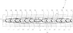
Fig. 3 is the front view of the preferred embodiment for the present invention.
Fig. 4 is the top view of the preferred embodiment for the present invention.
Fig. 5 is the explanation of the typical mounting structure of the antenna that provides of the preferred embodiment for the present invention.
Fig. 6 A, 6B and 6C are called Fig. 6 together, are the selectable appearance and the end views of a dielectric substrate of a radiant element of the preferred embodiment for the present invention.
Fig. 7 A, 7B, 7C and 7D are called Fig. 7 together, are the perspective view and the end views of a radiant element of the preferred embodiment for the present invention.
Fig. 8 is the size of a radiant element of the preferred embodiment for the present invention.
Fig. 9 A, 9B, 9C and 9D are called Fig. 9 together, are end view, top view and the perspective views of the combination of a radiant element of the preferred embodiment for the present invention and a mounting panel.
Figure 10 is the block diagram of a polarization state Control Network of the preferred embodiment for the present invention.
Figure 11 is the block diagram of a polarization state Control Network of an alternate embodiments of the present invention.
Figure 12 is the block diagram of a polarization state Control Network of an alternate embodiments of the present invention.
Figure 13 is the block diagram of a polarization state Control Network of an alternate embodiments of the present invention.
Figure 14 is the block diagram of a polarization state Control Network of an alternate embodiments of the present invention.
Figure 15 is the schematic diagram of the wireless-electric ground level of an alternate embodiments of the present invention.
Figure 16 is the schematic diagram of the wireless-electric ground level of an alternate embodiments of the present invention.
Figure 17 is the schematic diagram of the wireless-electric ground level of an alternate embodiments of the present invention.
Figure 18 is the schematic diagram of the wireless-electric ground level of an alternate embodiments of the present invention.
Embodiment
Antenna of the present invention is used for the application of radio communication, as personal communication service (PCS) and cellular mobile radio-phone (CMR) service.This antenna uses the polarization state diversity technique to alleviate harmful weak effect and the interruption that is caused by complicated transmission environment.This antenna contain a pair of polarization state radiating element arraying and have a bundle that is used for the power distributing network that array excites form network B FN).With radiant element, can in a wide antenna footprint, produce basic rotation symmetric figure as the conductive surface of wireless-electric ground level.Connect the mechanism that a control polarization state is provided with a polarization state Control Network (PCN) of this array through this distribution network center.
Those professional and technical personnel can find out easily that the sky linear polarization characteristic of difference can limit the power delivery of available communication system.Before antenna execution mode provided by the present invention was discussed, the outstanding feature of looking back an antenna with dual-polarization step response was very useful.
Generally, the pay upright leaf expansion of the far field of an antenna in the spherical coordinate system of standard is:
E whereinΘAnd EФBe electric field component on Θ, the Ф direction in the standard ball coordinate system.Unit vectorux,uy,uzBe with the corresponding rectangular coordinate system with same origin in x, y, z axle unanimity.
Generally, coefficient is that plural number is to comprise the situation of all polarization states and azimuth PHASE DISTRIBUTION.Because the purpose has here been ignored two faciation position and spreading factors that field component is common.If bundle has " pseudo-circular symmetry ", then the field can accurately be represented by a single expansion item (m=1).On symmetry axisuyThe electric field of direction (E field), ' pseudo-circular polarization symmetry ' field can be expressed as:
E1(Θ,Ф)=f1(Θ)sin(Ф)uΘ+f2(Θ)cos(Ф)uФ
F wherein1(Θ) and f2(Θ) be the transversal (cuts) of main shaft plane normalization field pattern, it changes by single order cosine and multifrequency sinusoid describes.Unit vectoruΘWithuФBe respectively Θ, the Ф direction.Above formula supposition adopt the spherical coordinate system of a standard, wherein electric field plane (E plane) is Ф=90 °, H plane (H plane) is Ф=0 °.On the symmetry axisuxThe electric field of direction (E field) can be expressed as:
E2(Θ,Ф)=F3(Θ)cos(Ф)uΘ-f4(Θ)sin(Ф)uФ
The condition that two polarized components satisfy orthogonality is:
E1(Θ,Ф)·E*2(Θ,Ф)=0
Wherein represent inner product, and * represents complex conjugate.Therefrom can draw following formula:
Therefore, if following formula set up, then orthogonality can set up and and view angle-independent:
f1(Θ)f3*(Θ)-f2(Θ)f4*(Θ)=0
During Θ=0 °, the normalization field component is 1, and it satisfies orthogonality condition.When departing from symmetry axis, the main shaft plane radiating pattern that satisfies two basic polarization states of orthogonality condition will have some independent conditions.Generally, at each Θ value place, the product of the E planar graph of two basic polarization states should equate with the product of H planar graph.Distribute if the supposition figure has equiphase, then problem can further be simplified, and the unique conditional that satisfies orthogonality is that figure must be the circumference symmetry.When the symmetry of figure reduced, the degree of quadrature also can depart from ideal case.
Ф-Ф in the field equation0→ Ф alternative finished on the antenna symmetry axle polarization state from consistent with x-y axle the rectangular coordinate system to Ф=± Ф0The transformation of corresponding to axle.When present dynasty+z direction is observed, define be tilted to the left (SL) and rotate on the antenna symmetry axleuyThe E field of direction, be tilted to the right (SR) rotates on the antenna symmetry axleuxThe E field of direction, then the field can be expressed as:
Thedefinition 3 of A.C.Ludwig has been adopted in the definition of " orthogonal polarisation state " herein, and " definition of orthogonal polarisation state ",IEEETrans.AntennasPropagat., Vol.AP-21, pp.116-119, January1973.The contour of theoretical fundamental radiation of known Huygens source has been described in definition 3.Huygens source is the combination of the electric dipole and a magnetic dipole of an equal strength and quadrature.Huygens source is unique in the mixture of all electric dipoles and magnetic dipole, wherein when it around its ground symmetry axis (uz) revolve when turning 90 degrees (from all visual angles) the complete field quadrature that is produced with non-rotating source that produces.Therefore, if two Huygens sources (the phase mutual deviation is 90 degree really on the Ф direction in the spherical coordinate system of a standard) are selected as two radiant elements of a dual-polarization attitude antenna, they will produce the basic polarization state (with view angle-independent) of a pair of quadrature always.Therefore, when exciting the radiator of these two quadratures with certain amplitude and phase weights, the polarization state that they produced only changes on inclination direction for the polarization state on the synthetic symmetry axis, and relevant with the polarization state on the symmetry axis that synthesizes.
The characteristics of Huygens source are one of relevant required characteristics of quadrature radiator during the polarization state diversity is used.Certainly, just better if the inclination angle does not change yet; Yet owing to set up the difficulty of polarization state definition, defining constant inclination angle is how much to be very difficult.Because for unique user, communication link is only relevant with a single polarization state, and the basic problem relevant with optimum polarization state covering performance is provided is the orthogonality of polarization state.Except optimizing day condition of linear polarization performance, some required graphic characteristicses have also been attached.
In order to describe the main feature of preferred implementation of the present invention, radiating element arraying is along the y axle in the standard straight angle coordinate system, and is positioned at the x-y plane.The plane, inclination angle of this array be defined as pass the bundle peak value the plane and along the y axle.Azimuthal plane is perpendicular to the plane, inclination angle, the transversal transmitted beam peak value of primary flat figure.
If interelemently in the array intercouple sufficiently lowly, then polarization state is optimized required graphics request and can be applied to a radiant element separately.The polarization state of the field that Huygens source array is produced and a single Huygens source produced polarization state identical.Because it is the figure of an isotropic radiator array, array factor does not have polarization state character.This point is very important in the present invention, because the radiating pattern intensity in the plane, inclination angle can be realized by selecting array element and the graphic characteristics of the polarization state of radiated wave in azimuthal plane is complete by the geometry control of array basically.
For a linear array, the preferred orientations of element polarization state is to tilt (± 45 °) with respect to array (y axle), there to be the balance that also can obtain the best under the situation that intercouples on the element symmetry of figure between the array element.When element was positioned at the center of ground level, direction was identical along the boundary condition of the major axis of array and the limited wireless-electric ground level of minor axis and two orthogonal polarisation state elements.
Usedefinition 3, on the antenna symmetry axleuyThe reference (copline) of the E field of direction and the unit vector of cross-polarization field are defined as:
eref(Θ,Ф)=sin(Ф)uΘ+cos(Ф)uФ
ecross(Θ,Ф)=cos(Ф)uΘ-sin(Ф)uФ
On the antenna symmetry axleuxThe reference (copline) of the E field of direction and the unit vector of cross-polarization field are defined as:
eref(Θ,Ф)=cos(Ф)uΘ-sin(Ф)uФ
ecross(Θ,Ф)=sin(Ф)uΘ+cos(Ф)uФ
For SL and SR polarization state, by substituting the Ф of 45 ° of rotations, and adopt and to obtain it with identical just now mode and define with reference to unit vector with orthogonal polarisation state.
The graphic feature of array in the azimuthal plane of Ф=0 ° that has the polarization state of two inclined element characteristics through discussion illustrated some characteristics of antenna provided by the invention.At first, Electric Field Distribution can be write out with the form of reference and orthogonal polarisation state component:
The orthogonal polarisation state figure has been formed half of master (E-and H-plane) figure difference of radiant element.Zero orthogonal polarisation state has implied the complete rotational symmetric condition of copline figure.Zero orthogonal polarisation state is corresponding to the orthogonality in dual-polarization attitude source.
In addition, on inclination polarization field and the antenna symmetry axleuyThe inner product of the reference polarization state of the E field of direction has produced and has been half the figure of the product factor of radiant element normalization copline H-planar graph.On inclination polarization field and the antenna symmetry axleuxThe inner product of the reference polarization state of the E field of direction has produced and has been half the figure of the product factor of radiant element normalization copline E-planar graph.Except that only when the radiant element figure be fully when symmetry rotation all half invariant, the coverage in the azimuthal plane is identical.Except that invariant, the characteristics with identical graphical distribution are to use a key character of used antenna in the communication system of polarization state diversity technique.Otherwise when collimation departs from when reaching 45 °, linear polarization signal will be greater than desirable polarization state mismatch to the amplitude difference of the polarization state coupling of this linear polarization antenna, thereby causes the polarization state diversity performance of non-optimum.When having the polarization state orthogonality, the dying down of this polarization state stiffness of coupling, promptly being coupled for ideal case diminishes, and comes from the degree of quadrature.
Another characteristics of a rotation symmetrical radiation pattern are, when adopt different weights will with corresponding two bundles of the polarization state of dual-polarization element characteristics combine form the polarization state that is different from nature element polarization state to the time, the azimuth figure feature of array will remain unchanged.This ability is a very significant application of the present invention.Although be used for illustrating that the example of main polarization state feature is the linear polarization situation, it for other polarization state to also setting up.Be appreciated that two circular polarization states (dextrorotation and left-handed) also can be used to adopt the wireless communication system of polarization state diversity.
Go to accompanying drawing now, wherein same numeral is represented components identical, and Fig. 1 is the block diagram of the main element of the explanation preferred embodiment for the present invention.With reference to figure 1, wherein anantenna 10 uses the high-frequency spectrum exchange electromagnetic signal relevant with legacy wireless communication system.Thisantenna 10 can be aradiator element 12, baud generator of promptly knowing or radiator, planar array, during wherein from the top view aerial position, this array direction is parallel to the vertical plane of antenna.For the execution mode of preferred linear array, when not adopting when overlooking (machinery or electricity), array factor has mainly formed the covering the plane, inclination angle in, and the interior covering of its azimuthal plane mainly is subjected to the influence of element graphic feature.Generally, this linear array can be classified as a Fanned Beam Antenna, and the ratio of the length size of the crosscut section of the main lobe that it produces is big.
Can send antenna 10 with receiving electromagnetic signals and comprise 14, one bundles of 12, one ground levels of radiant element and form networks (BFN) 16, and a polarization state Control Network (PCN) 18.This radiant element 12 is a baud generator, comprises element 12a and 12b with dual-polarization attitude, and preferred arrangement is a linear array and on the conductive surface of ground level 14 and from it a preset distance is arranged.Radiant element 12 provides required graphic feature with ground level 14 tandem workings to give antenna 10.The radiating pattern of antenna 10 has basic rotational symmetry, for the convenience that illustrates, rotational symmetry be defined as having " pseudo-circular symmetry " and in all visual fields of antenna for any θ value place, the difference between primary flat (E-and H-plane) figure is no more than rough 3.The common polarization state graphic response of 1dB.Alternatively, high rotation symmetrical radiation pattern can be defined as one and have " pseudo-circular symmetry " and in all visual fields of antenna the ratio between the orthogonal polarisation state less than generally-the common polarization state graphic response of 15dB.For the preferred implementation of antenna 10, the linear array of a dual-polarization attitude radiant element is in very wide visual field, and typically the scope of half power beamwidth (HPBW) (HPBW) is in 45 to 120 degree, has the rotation symmetrical radiation pattern.
Link to each other with 12b with radiant element 12a as the BFN16 of a distribution network, transmitting received signal from radiant element, and to radiant element transmission signal.The PCN18 that links to each other with BFN16 can control the polarization state of the received signal of BFN16 distribution.Becauseradiant element 12 has the dual-polarization attitude, PCN18 can receive the received signal of arbitrary polarization state, and has the electromagnetic signal of a polarization state P1 in 22 outputs of first delivery outlet, has the electromagnetic signal of a polarization state P2 in 24 outputs of second delivery outlet.
Becauseantenna 10 generally is used for PCS and CMR uses, the technical staff of this respect should find out at an easy rate that the best features ofradiant element 12 is generally high efficiency, wide radiating pattern, high polarization state purity and enough bandwidth of operation.In addition, ifradiant element 12 is in light weight, expense is low, can directly carry out interface with BFN16, and can be integrated with the encapsulation of antenna, just ideal more.Dipole antenna satisfies the requirement of all these electrical properties, and the execution mode of printed circuit satisfies the physics requirement.With following will with reference to figure 6 describe in detail the same, the preferred implementation of each radiator 12a and 12b is one to have and be tilted to the left (SL) and the dipole-type antenna of the polarization state of be tilted to the right (SR).
Fig. 2 is the stereogram that makes the critical piece of the very eye-catching antenna 10 of the preferred structure of antenna.Fig. 3 and 4 is respectively the front view and the top view of antenna 10.With reference to figure 2-4, each radiant element preferably contains two dipole antennas, and each has an a pair of dipole arm and a dipole basic point, and it is right that they are brought together to form a cross-dipole.The right electrfic centre of cross-dipole overlaps, and makes thus by supplying with the caused any phase delay of these dipole antennas to become minimum.Wireless-electrical ground the top of the preceding conductive surface on plane of each cross-dipole to being positioned at that ground level 14 provides.Especially, cross-dipole is on the conductive surface that is installed on capacitive plate 20, and this capacitive plate is installed on ground level 14 successively.Arranging the right direction of cross-dipole like this is the basic point that is positioned at dipole for the feed that makes dipole, the basic point of dipole arm represent any point on the dipole over the ground interplanar every ultimate range.Dipole arm scans with anti-" V " shape towards ground level 14 downwards.Can the sub-arm of electrode couple height on ground level 14 surfaces and the angle of dipole arm be optimized, on ground level 14, forwards upwards to obtain very high rotation symmetrical radiation pattern feature.Describe the preferred size of an Antenna Design dipole antenna and its line of feeding in detail below with reference to Fig. 8 with 90 degree half-power azimuth beamwidths.
BFN16 is supported by the preceding conductive surface ofground level 14, and to the dipole antenna ofradiant element 12 with from its distribution electromagnetic signal.BFN16 uses a pair of distribution network to be used for the structure of dual-polarization attitude array, and wherein each is used for a polarization state.BFN is preferably the microstrip line design, and provides suitable impedance matching between eachradiant element 12 and PCN18.In addition, BFN16 preferably comprises a power divider with to eachradiant element 12 distribute signals.
PCN18 is supported by the preceding conductive surface ofground level 14, and is positioned at the center of antenna integral body, and is connected between distribution network BFN16 and a pair of antenna opening 22 and 24, and each antenna opening can link to each other with the cable of feeding.PCN18 through BFN16 to fromradiant element 12 distribution electromagnetic signals, and provide a complex weight (amplitude and phase place) for these signals.In a preferred embodiment, PCN18 is designed to a polarization state controlling mechanism that has four external interfaces that link to each other with transmission line at least.In four external interfaces two link to each other with distribution network BFN16, and two remaining external interfaces link to each other with 24 with antenna opening 22, and these two antenna opening are continuous to be connected source and antenna with the cable of feeding successively.
Although preferably PCN18 is installed in the Anneta module, be appreciated that PCN18 also can be installed on outside the antenna base.If PCN18 is not installed inantenna 10 modules, distribution network BFN16 can provide suitable impedance matching atradiant element 12 and each cable of feeding that is connected between antenna opening 22 and 24.In this embodiment, each antenna opening 22 and 24 has suppressed the signal reflex along this transmission line thus corresponding to one of two polarization states.Being appreciated that can be according to the special applications of antenna and be installed on PCN18 inantenna 10 modules or be installed on outside the antenna base.For example, PCN18 can be installed on laying a little of pedestal, andradiant element 12, andground level 14 can be installed in the Anneta module at antenna place with the combination of BFN16.
The conductive surface ofground level 14 is as the entire antenna module, and a construction package that forms the wireless-electric ground level of dipole element.Ground level preferred embodiment is a solid, very flat basically sheet of conductive material.Wireless one electric size (width) of the transverse plane of aerial array is roughly 5/3 wavelength, forms radiator element (to be typically greater than 60 degree) in wide visual field, and can not make the finite boundary condition ofconductive ground plane 14 influence radiation characteristic significantly.Whenground level 14 wireless-when electric size satisfied above-mentioned condition, the direction ofradiant element 12 can be rotated and be consistent with the main shaft of array, and can seriously not reduce the rotational symmetry of antenna radiation pattern.But preferred and best direction is that the antenna symmetry axle polarization state of nature is 45 ° with respect to the primary flat of array.
The data acknowledgement that experience is derived although bigger lateral dimension generally can cause the minimizing of backward radiation figure power, can not play a very important role to improving rotational symmetry.Use for some, the lower powered radiating pattern in the back on direction is called back lobe district (backlobe) and wants, but the degree that back lobe district reduces need and size, weight, expense, and wide load characteristic increase trade off.
Wireless-measurement that electric ground level carries out with less lateral dimension shown when lateral dimension be roughly 1.Can cause dispersing of undesirable figure beamwidth during 5 wavelength.And the ground level with littler lateral dimension can make the azimuth beamwidth more responsive to the number of array element.This drawback also can be attended by departing from required rotation symmetrical radiation pattern.
Measure also explanation, for the vertical radiator of the direction parallel with array plane, wireless-electric the size ofground level 14 in the array transverse plane can be made more much smaller than above-mentioned criterion, and can not make the azimuth beamwidth very responsive to size in the scope of a broad of smaller value.But the parts of horizontal polarization (physics or synthetic through PCN) but do not have this independence.Because this needs the dual-polarization attitude in using, and preferably has the electrfic centre of coincidence, two polarization states need adopt identical size criterion, and wherein the horizontal polarization component condition is an a crucial factor.
The radome 26 of a protectiveness comprises a thermoplastic material, can containradiant element 12 arrays, BFN16, PCN18, eachcapacitive plate 20, and the combination of the preceding conductive surface of ground level 14.Radome 26 is connected in the edge ofground level 14 with screw 28, and round the preceding conductive surface ofground level 14 and above the element installed.The sealing of the antenna inground level 14 and radome 26 formed sealing shells can protect antenna element not to be subjected to the influence of environment, as directly shining upon, and directly water, pollutant, rubbish and humidity.Radome 26 contained thermoplastic material are preferably KleerdexCompanyofAiken, and the product of SouthCarolina company, its trade mark are " KYDEX ", as " KYDEX100 " acrylic acid PVC alloy sheet.
Antenna can be installed on the erection column through a pair of fixed mount 30 that links to each other with conductive surface behind the ground level 14.A staple (not shown) can be fixed in Anneta module on one erection column together with fixed mount 30.Although the preferred mounting structure ofantenna 10 is through an erection column, be appreciated that and adopt many other traditional installation methods to come supportingantenna 10 that comprise that pylon supports, combined support or other be element independently.A typical case ofantenna 10 installs and is shown in Fig. 5, will describe Fig. 5 in detail below.
Antenna opening 22 and 24 preferably is designed to the socket with the coaxial cable compatibility, as N type socket, and links to each other with the rear surface ofground level 14 with 34 through capacitive plate 32.Each capacitive plate 32 and 34 comprises the roughly identical dielectric layer with conducting strip of a conducting strip and a size adjacent with conducting strip.When fixing up an aerial wire module, contiguous each mouthful 22 in the installation site of conducting strip and 24 and the socket coaxial cable compatibility, and dielectric layer is clipped betweenground level 14 and the conducting strip with the formation sandwich structure.In this mode, antenna opening 22 and 24 andground level 14 between current path wireless-electrically connect as one " capacitive coupling ".The area of conducting strip is sufficiently greatly to realize Low ESR in operating frequency range.Dielectric layer by avoid antenna opening 22 and 24 withground level 14 between directly carry out metal-metal and be connected to come as direct current (DC) barrier layer.This capacitive that is used for reducing passive cross modulation effect is coupling in the U.S. Patent Application Serial Number NO of the application on February 27 nineteen ninety-five that same assignee has.Describe in detail in 08/396,158 the explanation, use for referencial use here.
Antenna shown in Fig. 2-4 is mainly used to support the interior communication service of personal communication service (PCS) frequency range of 1850-1990MHZ.But, those skilled in the art as can be seen, the size that can change antenna supports preferably to be operated in the exemplary cellular telephone communications applications in the 805-896MHZ frequency range roughly.Similarly, the size that can change antenna is supported the communication service in Europe to comprise that frequency range is the global system for mobile communications (GSM) of 870-960MHZ or the European PCS that frequency range is 1710-1880MHZ.These frequency ranges have been represented the example of operating frequency of antenna scope, are below or above these and the relevant frequency range of PCS application but can expand to.
Importantly, theantenna 10 shown in Fig. 1-4 is the radiant element planar arrays with dual-polarization attitude, and the radiating pattern that has basic rotational symmetry in a wide visual field is arranged.For example, illustrative Antenna Design has the HPBW of one 90 degree in the azimuthal plane of antenna, and this is that combination by dual-polarization attitude radiant element and ground level realizes.In contrast to this, the half power beamwidth (HPBW) in the plane, inclination angle is by the aerial array size, and promptly the number and the inter-element spacing of radiant element in the planar array are realized in advance.Although the antenna shown in Fig. 1-4 has 90 degree HPBW, the HPBW beamwidth of other execution mode can be spent to 120 degree from 45.Importantly, in the HPBW of at least 45 degree, the relevant execution mode ofantenna 10 should have the radiating pattern of very high rotational symmetry.
Fig. 5 is the typical installation instructions ofantenna 10 that are used for an antenna system of a pcs system.What Fig. 5 emphasized is, is divided in the sector cell structure of K individual cell in the azimuth coverage, andantenna 10 is very useful.In this representational example, three antennas are arranged,antenna 10a, the point of three sectors (K=3) of 10b and 10c is positioned at the center of base station, and each antenna has 120 to spend the coverage of (radian) in azimuthal plane, and its effective covering radius is by the gain of antenna, highly, and the angle of depression decision ofbundle.Antenna 10a, the top of 10b and the 10c rear surface through being fixed in each antenna and bottom mounting and fixing support 42 are installed on an erection column 40.Although the antenna of Fig. 5 10 has used an erection column, be appreciated that installed hardware can be smooth in the side of combined support frame with Anneta module, and the column structure that module is installed to a post or pylon support.
The example of Fig. 5 has illustrated website when space diversity transforms to the polarization diversity technology, and the general desired big antenna structure that physically antenna separation is come is replaced.Adopt the polarization diversity feature of preferred antenna, can three Anneta modules be installed on the single erection column with hardware is installed, to realize the coverage of three sectors.It will make Anneta module diminish at the area of coverage on ground, and this is very favorable, and it will be littler than present space diversity reception to communicate system to the influence of visual environment.
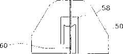
Fig. 6 comprises Fig. 6 A, 6B, 6C, illustrated respectively the preferred implementation that supports a radiant element front view, end view and the rearview of dielectric-slab.At first with reference to figure 6C, a dipole antenna 52 of each radiant element 12 is formed at a side of a dielectric-slab 50, and is metallized the bus with the necessity that forms a pair of dipole arm 54 and dipole daughter 56.Dipole antenna 52 by photoetching (being also referred to as photomask) on the dielectric substrate of dielectric-slab 50.The width of the bus of selection formation dipole arm 54 is to provide enough working impedance bandwidth to radiant element.Dipole daughter 56 is arranged on the similar face that dipole arm 54 occupies, and dipole daughter 56 has comprised the bus that dipole arm 54 is electrically connected with capacitive plate 20 (Fig. 2) of pair of parallel.With the capacitive plate 20 that describes in detail with reference to figure 9 in the back as a mechanical support and between the conductive surface of the dipole of quadrature pair and ground level 14 formation wireless-be electrically connected.Form the length of these buss of quadrature position of feeding line 58 (Fig. 6 A) at the back side of dielectric-slab and be roughly 1/4th of selected band center wavelength, and as a balanced-unbalanced transformer.The width of these buss increases and provides a wireless preferably-electric ground level near the pedestal of dipole element to give at little band at the back side of dielectric-slab line 58 (Fig. 6 A) of feeding.
As shown in Figure 6A, at the back side of dipole antenna 52, theline 58 of feeding that energy is coupled to dipole arm 54 (Fig. 6 C) of a microstrip line form is arranged.The same with the front, this littleband feed line 58 by photoetching on the surface of dielectric-slab 50.The terminal of thisline 58 of feeding is counted from crossover location for open circuit, and the open end length of theline 58 of feeding is roughly 1/4th of working band centre wavelength.The preferred implementation ofline 58 of feeding is that near the impedance in pedestal from dipole antenna 52 (Fig. 6 C) zone to the crosspoint is 50 ohm.
Shown in the end view of Fig. 6 B, dielectric-slab 50 is relative very thin dielectric material sheets, can be many kinds of low loss dielectric materials as wireless-circuit.The material of preferred implementation is MC-5, and its tangent loss is low, and relative dielectric constant is 3.26, and is non-hygroscopic relatively, and price is also low relatively.MC-5 is positioned at Collierville by GlasteelIndustrialLaminates, and the branch of the Alpha company of Tennessee makes.The substitute of lower price is moisture absorption as FR-4 (a glass epoxy mixture), generally must seal when being used for outdoor environment with anti-sealing absorption fully.Water absorbs the drain performance that will reduce material.The material based on polytetrafluoroethylene (teflon Teflon) of higher price also can be used as substitute, but does not have advantage clearly.
Although the preferred implementation of eachradiant element 12 is the printed dipole antenna form, is appreciated that and adopts other dipole antenna execution mode to come constructing antennas 10.Other traditional dipole antenna execution mode also can be used for constructing antennas 10.In addition, be appreciated that alsoradiant element 12 can not adopt dipole antenna to realize the function of antenna.
Fig. 7 A, 7B, 7C and 7D, adding up is called Fig. 7, and the different views that cross-dipole is right has been described.At first referring to Fig. 7 A and 7B, the metal medium plate core that is not plated to of each dielectric-slab 50 has agroove 60, and it separates the parallel band of dipole daughter 56.One group of crossedgrooves 60 in a pair of dielectric-slab 50 has realized that the physically mutually orthogonal orthogonal dipole antenna of direction is to 52.Shown in Fig. 7 C and 7D,little band line 58 of feeding is in the intersection region with a kind of up-down structure alternately and is in contact with one another to prevent two lines of feeding.Except near the details the intersection region ofline 58 of feeding was different, this dipole antenna to the direction quadrature was roughly the same to 52 feature.The width of dipole daughter 56 is not both for the reference position on the radiant element pedestal being formed the same impedance coupling of equivalence.
With reference now to Fig. 8,, Fig. 8 is the preferred size that is used for the dipole antenna configuration of PCS frequency range, and wherein eachradiant element 12 contains and has the design of sweeping downwards to form the dipole arm 54 of anti-" V " shape.During installation, the height on dipole arm isliftoff plane 14 roughly is.26 wavelength.The angle of dipole arm 54 is roughly 30 degree.The entire scope of the sub-arm 54 of this electrode couple roughly is 1/2nd wavelength, and its width is roughly.38 wavelength.The height on the summit on dipole arm 54 low limits and the height of body 56 are.19 wavelength.The center of gravity of dipole arm 54 is near the summit of dipole antenna 52, and its height is roughly.22 wavelength.The width that is appreciated that dipole arm 54 is to be scheduled to from the angle of frequency band range.For example, the working impedance frequency band of a narrow dipole arm is less.In addition, the details of geometry that is appreciated that the summit of the low limit of dipole arm 54 and body 56 can not influence antenna performance significantly except influencing impedance operator.
Fig. 9 A, B, C and D, adding up is called Fig. 9, illustrated with the radiant element of quadrature wireless to being installed to-different views of preferred structure on the electric ground level.With reference to figure 9, current path is wireless between each dipole 52 and the ground level 14-be electrically connected by the capacitive formation that is of coupled connections.Especially, acapacitive plate 20 is connected each dipole 52 of a cross-dipole centering with the conductive surface of ground level 14.Can be with this capacitive sleeve-board together so that production be easier.Capacitive plate 20 has a conductive plate 70 and a dielectric layer 72.The conductive surface area of conductive plate 70 is sufficiently greatly to provide a low impedance path in working band.This film dielectric layer 72 has two functions: intercept direct current (DC) and can both sides bonding mechanically to limit cross-dipole to the position of module on ground level 14.Capacitive plate 20 avoid adopting height wireless-direct connection that electrical power such as hundreds of bricklayer can produce the metal-metal node of passive crossover frequency modulation when doing.
Conductive plate 70 is preferably a sheet tin copper sheet structure, with can form mechanical support quadrature radiator to and have a required form of the electrical connection that can weld the conductive microstrip that the capacitive plate is linked to each other with little band of dipole daughter.To being designed for the preferred implementation that PCS uses, the roughly thickness of conductive plate 70 is 0.010-0。020 inch.Dielectric layer 72 is preferably has St.Paul, the both sides that are called ScotchVHB that the 3M company of Minnesota produces are a dielectric material of stick.For preferred implementation, selected dielectric material thick 0.002 inch, and the same with the capacitive plate at least wide, preferably be cut into the same with the width of capacitive plate.
Figure 10 is the block diagram of the PCN preferred components of antenna 10.With reference now to Figure 10,, preferred PCN and a pair ofduplexer duplexer duplexer 80 is and has a distribution network ofradiant element 12 that is tilted to the left polarization state and link to each other, andduplexer 82 is and has a distribution network ofradiant element 12 that is tilted to the right polarization state and link to each other.The received signal that is tilted to the left polarization state that has of coming from distribution network BFN16 is responded, andduplexer 80 is exported this received signal through a delivery outlet.The received signal of coming from distribution network BFN16 is responded, andduplexer 82 is exported this through a delivery outlet and is had a received signal that is tilted to the right polarization state.The transmission signal that power combiner 84 receives from the source of transmission also passes to thissignal duplexer 80 andduplexer 82.Duplexer 80 andduplexer 82 can receive the transmission signal from power combiner 84, export this transmission signal to BFN16 successively again.According to the equiphase excitation of two basic polarization states that apply,antenna 10 gives off the vertical polarization attitude signal of an equivalence.
Be appreciated thatantenna 10 not only be confined to receive have one be tilted to the right polarization state and be tilted to the left polarization state signal and send the signal of a vertical polarization attitude.As shown in figure 11, a PCN18a contains the first polarizationstate control module 81 and output one second a polarizationstate control module 83 to received signal of accepting a pair of transmission signal from a transmission source.The first polarizationstate control module 81 links to each other with 82 withduplexer 80 with the second polarization state control module 83.Transmission signals TX1 and TX2 are responded, and the first polarizationstate control module 81 sends signal to duplexer 80 and 82 outputs.In addition,duplexer state control module 83 is exported received signal RX1 and RX2 again successively.In this way, these four mouths to duplexer 80 and 82 can be combined to provide required transmission and received signal right.Polarizationstate control module
Figure 12 is the block diagram of another alternate embodiments of a polarization state Control Network.With reference now to Figure 12,, a PCN18b contains one 0 °/180 ° type hybrid coupled device 85, one duplexers 86, and low noise amplifier (LNA) 87a and 87b.With BFN16, the hybrid coupler 85 that duplexer 86, LNA87a link to each other to transmit signal from distribution network BFN16.In addition, hybrid coupler 85 has the received signal of horizontal polarization attitude and has the received signal of vertical polarization attitude to duplexer 86 outputs one to LNA87a output one.Duplexer 86 contains common a mouthful of linking to each other with hybrid coupler 85, and a receiving port that links to each other with LNA87b and sends mouth.The common mouth of duplexer 86 is accepted to have the received signal of vertical polarization attitude and is distributed the transmission signal with vertical polarization attitude to hybrid coupler 85 from hybrid coupler 85, the receiving port of duplexer 86 has the received signal of vertical polarization attitude to LNA87b output, and sends mouthful transmission signal that acceptance has the vertical polarization attitude.Therefore, be appreciated that duplexer 86 can separate received signal and transmission signal according to the spectrum signature of signal.With LNA87a and the LNA87b that hybrid coupler 85 links to each other with duplexer 86 received signal is amplified to improve the signal-to-noise performance of signal respectively.LNA87a amplifies the received signal with horizontal polarization attitude, and LNA87b amplifies the received signal with vertical polarization attitude.Be appreciated that working as PCN is receiver end rather than the antenna place that is positioned at wireless communication system, can remove LNA87a and LNA87b from the structure of PCN18b.
A PCN who realizes with hybrid coupler can carry out respectively bilinearity inclination polarization state (SL/SR) with preferred implementation be transformed to a vertical/horizontal (V/H) polarization state to or the right math function of one right-hand circular polarization/Left-hand circular polarization (RCP/LCP).When radiating pattern was symmetrical for rotating, these polarization converted can not change the antenna azimuth figure beamwidth of copline radiant element.Use these hybrid couplers to realize the conversion of polarization state and can not change beamwidth necessary condition reasonably mated with group circuit footpath (phase delay) length in the corresponding path of physical feature polarization state of active antenna array.This identical matching condition is very necessary to amplitude characteristic.
Figure 13 is the block diagram of another alternate embodiments of a polarization state Control Network.With reference now to Figure 13,, a PCN18c contains one 0 °/180 ° type hybrid coupled devices 88, and for the polarization state diversity provides four polarization states, is vertical specifically, and level is tilted to the left and is tilted to the right, switch 89a-d.Switch 89a links to each other with distribution network BFN16 with the common mouth of 89b.In addition, closed usually mouthful links to each other with hybrid coupler 88 among switch 89a and the 89b, and the mouth of wherein opening usually directly links to each other with 89d with switch 89c.In a similar fashion, closed usually mouthful links to each other with hybrid coupler 88 among switch 89c and the 89d, and the mouth of wherein opening usually directly links to each other with 89b with switch 89a.Common mouthful of switch 89c and 89d as the delivery outlet that the received signal with selected polarization state is provided.
For state closed usually among the switch 89a-d, the work that hybrid coupler 88 inserts PCN18c, the state of opening usually among the switch 89a-d then is to be used for avoiding coupler 88.Therefore, for the state of opening usually, common mouthful of switch 89c and 89d as the received signal with the polarization state that is tilted to the left and is tilted to the right is provided.In contrast to this, for the state of common closure, the common mouthful of received signal that has the vertical and horizontal polarization state as output of switch 89c and 89d.This received signal that can permit a user to base station receiver is selected required polarization state.
Switch 89a and 89b can realize with single-pole double-throw switch (SPDT), and switch 89c and 89d can realize with single-pole double-throw switch (SPDT) or hilted broadsword four throw switches.
Figure 14 is the block diagram of another alternate embodiments of a polarization state Control Network.As shown in figure 14, PCN18d comprises the parts more than, when the situation of amplitude and/or unbalance in phase occurring between the polarization state parts of two natures, also can allow to carry out the conversion of polarization state and the beamwidth that can not change figure.PCN18d can be divided into a variable power distribution network by power division between the relative phase shift decision PCN mouth of phase-shifter 96 and 98.PCN18d contains the hybrid coupler 90 and 92 that a pair of centre is connected by a transport module 94 that is used to apply non-equilibrium phase shift.Its preferred implementation be one 0/90 degree type hybrid coupled devices hybrid coupler 90 be connected on the function input port 1 and 2 and transport module 94 between.Its preferred implementation be one 0/180 degree type hybrid coupled devices hybrid coupler 92 be connected on the function delivery outlet 3 and 4 and transport module 94 between.A pair of phase-shifter 96 and 98 in the transmission line of insertion transport module 94 can form phase shift between hybrid coupler 90 and 92.Phase-shifter 96 can be the different transmission line of length, i.e. a passive phase-shifter, or the variable phase-shifter that can control the phase shift between hybrid coupler 90 and 92 as shown in figure 14 with 98 preferred implementation.In addition, can between input port and hybrid coupler 90, insert a pair of phase-shifter 100 and 102 to control the phase shift of the signal that enters PCN18d fully.The structure of this PCN18d can be controlled the synthetic of polarization state fully, for example can produce any two orthogonal polarisation state to the characteristic polarization state as antenna.If one or more passive phase-shift units are substituted by a controllable phase shift device, then can under the situation that does not change the figure beamwidth, realize the flexibility of polarization state.
Refer again to Fig. 2-4, for the PCS frequency, it is 10 inches (5 λ that the cross direction wireless of ground level-electric size is demarcated0/ 3) to obtain required polarization state performance.When changing this parameter when adapting to lower frequency, when for example centre frequency was the typical cellular mobile wireless-telephone band of 851MHZ, the horizontal physical size of wireless-electric ground level increased.For this typical honeycomb frequency, the equivalent lateral dimension ofground level 14 is roughly 22.5 inches.The size of array plane is changed in an identical manner to obtain identical antenna directivity and to make the invariable number of array element.Be appreciated that horizontal physical size is minimized reducing wind loads and expense, and to improve overall performance be desirable by reducing antenna size.
Figure 15 is the explanation of an alternate embodiments of the ground level of antenna 10a.With reference to figure 1 and Figure 15, be appreciated that the array that is positioned at transverse plane for horizontal part, the lateral dimension of a wireless-electric ground level is to be encouraged by the figure of horizontal polarization attitude parts and polarization state feature.Can satisfy the electromagnetism boundary condition of horizontal polarization attitude and can not have a strong impact on the performance of vertical polarization attitude parts.This can use non-solid conductive surface to realize by reaching outside the required desired smallest lateral dimension of performance characteristics of vertical polarization attitude parts.This non-solid conductive surface shown in thestake Stake antenna 10a and are symmetrically located at the lateral dimension of two edges of antenna with the formation antenna, the i.e. side of ground level 14a.The typical construction technology of eachstake bonding jumper.Radome 26a contains the top of groove with eachstake element 112 of holdingstake
Test data proves that for most of geometries, vertically the energy of (vertically) polarization state is influenced bystake element 112 of each stake roughly is S=λ0/ 3 to λ0/ 2.This element spacing allowsstake
Ifstake element 112 is embodied as along the edge outwardly and in the face of the bus on the surface ofantenna 10a, the loss of transmission signal of parts that then has the parallel polarization attitude is bigger, and the reflectivity of equivalent conductive surface increases.Therefore, be appreciated that and between the interval of center to center and the degree of depth, trade off to reach required performance.
For the PCS frequency, empirical data shows the performance that lateral dimension will provide for vertical polarization attitude parts for a solid ground plane 14a of 4-6 inch.For the physical embodiments of this ground level 14a, it is the required polarization state and the coverage of 10 inches wireless one electric ground level equivalence to provide with the solid conduction surface size that this length to thestake element 112 of thestake 110a of horizontal direction and 110b should be roughly the 2-3 inch.
For centre frequency is the honeycomb frequency of 851MHZ, can think that a solid conduction of 12 inches plane 14a electrical property that can provide for 6 inches a pair ofhorizontal stake
Another advantage of using stake is to superpose in the equiphase field of each joint edge geometries at the aerial array back side partly to have been destroyed, and therefore most of signal state of polarization has been increased the figure envelope performance (front-to-back ratio patter envelopeperformance) of front to back side ratio effectively.
When being operated in lower frequency, from the angle that actual physics is realized, the use of stake element arrays is just more important.For example, for 450MHZ, effective cross direction wireless of ground level-electric size should be roughly 43 inches.The principle of the application of the invention, can be that wireless-electric ground level is come together to realize with a pair of stake element arrays in 22 inches solid conduction surface with approximate size, wherein each stake element extends roughly 10 along the length direction of the parallel sides on this solid conduction surface.5 inches.
Figure 16 and 17 has been to use an alternate embodiments of the wireless-electric ground level of antenna of the present invention.With reference now to Fig. 1,, 16 and 17, Figure 16 has illustrated to have theantenna 10b ofplane 14b agley, and Figure 17 has illustrated to have piecemeal the antenna 10c of plane 14cagley.Ground level 14b is the conductive surface of a convex form, and whereinradiant element 12, and BFN16 is installed by the center with the outward flange of convex form of structure that PCN18 can-electric ground level wireless along this semicircle.In contrast to this, the ground level 14c of antenna 10c one has the conductive surface of the curved shape of being made up of a central horizontal element and a pair of azimuth element that extends along each limit of this central horizontal element piecemeal.Althoughradiant element 12 is preferably supported by the horizontal cell of ground level 14c, BFN16 and PCN18 can be supported by the horizontal surface of center part and the azimuthal plane of edge member.The essence ofground level 14b and 14c bending is that the finite boundary of conductive surface of-electric ground level wireless in order to reduce is to the influence of aerial radiation characteristic.
With reference now to Figure 18,, has the quarter-wave (λ that the degree of depth is roughly the working band centre frequency on the both sides of its solid ground plane 1220The antenna 10d of one or more chokes grooves 120/4) can reduce the integral edge diffraction coefficient of horizontal polarization attitude parts, and wireless-similar cover graphics of electric ground level and the polarization state performance with large-size is provided.Equal with the surperficial defined plane of the conductive plane of ground level 122 by the opening that makes choke groove 120, the size of ground level 122 can reduce to roughly wavelength (λ0).Choke groove 120 contains the transmission line of a joint parallel-plate shape, and mouthful is roughly the quarter-wave strong point by short circuit leaving.This parallel-plate transmission line can be at wireless-electric ground level spine folded to reduce the degree of depth of whole module.As shown in figure 18, the single choke groove 120 along array main shaft edge is configured to vertical with the plane and does not have fold simply.
When the main shaft of antenna has more than one choke groove, the bigger performance of improving will be had.But, when the width of parallel-plate is typical 1/10th wavelength (λ0/ 10) time, even to module increase thickness and every limit two or more grooves are arranged, the advantage that size reduces will disappear and be tending towards complete size (5 λ0/ 3) ground level.Compare with the simplicity of the execution mode of solid or hybrid solid/non-solid ground level, the module complexity that making two or more chokes grooves on every limit is increased will not have attraction.
Only be appreciated that claims have subsequently defined scope of the present invention, and foregoing description only is to be used for describing various execution mode of the present invention.Especially, scope of the present invention can extend to outside any detailed execution mode of this declarative description.
Claims (25)
Translated fromChineseApplications Claiming Priority (2)
| Application Number | Priority Date | Filing Date | Title |
|---|---|---|---|
| US08/572,529US5966102A (en) | 1995-12-14 | 1995-12-14 | Dual polarized array antenna with central polarization control |
| US08/572,529 | 1995-12-14 |
Publications (2)
| Publication Number | Publication Date |
|---|---|
| CN1208505A CN1208505A (en) | 1999-02-17 |
| CN1262046Ctrue CN1262046C (en) | 2006-06-28 |
Family
ID=24288235
Family Applications (1)
| Application Number | Title | Priority Date | Filing Date |
|---|---|---|---|
| CNB961998865AExpired - Fee RelatedCN1262046C (en) | 1995-12-14 | 1996-12-11 | Dual Polarization Array Antenna with Central Polarization Control |
Country Status (8)
| Country | Link |
|---|---|
| US (2) | US5966102A (en) |
| EP (1) | EP0867053A4 (en) |
| JP (1) | JP3856835B2 (en) |
| CN (1) | CN1262046C (en) |
| AU (1) | AU1130597A (en) |
| BR (1) | BR9612664A (en) |
| CA (1) | CA2240182C (en) |
| WO (1) | WO1997022159A1 (en) |
Cited By (1)
| Publication number | Priority date | Publication date | Assignee | Title |
|---|---|---|---|---|
| US10879619B2 (en) | 2009-06-04 | 2020-12-29 | Ubiquiti Inc. | Microwave system |
Families Citing this family (306)
| Publication number | Priority date | Publication date | Assignee | Title |
|---|---|---|---|---|
| FR2746991B1 (en)* | 1996-03-28 | 1998-06-12 | Nortel Matra Cellular | RADIO STATION WITH CIRCULAR POLARIZATION ANTENNAS |
| US6900775B2 (en)* | 1997-03-03 | 2005-05-31 | Celletra Ltd. | Active antenna array configuration and control for cellular communication systems |
| AU6228898A (en)* | 1997-03-03 | 1998-09-22 | Joseph Shapira | Cellular communications systems |
| CA2240114A1 (en)* | 1997-07-03 | 1999-01-03 | Thomas P. Higgins | Dual polarized cross bow tie dipole antenna having integrated airline feed |
| FR2766626B1 (en)* | 1997-07-28 | 1999-10-01 | Alsthom Cge Alcatel | CROSS POLARIZATION DIRECTIONAL ANTENNA SYSTEM |
| US6094165A (en)* | 1997-07-31 | 2000-07-25 | Nortel Networks Corporation | Combined multi-beam and sector coverage antenna array |
| US6028562A (en)* | 1997-07-31 | 2000-02-22 | Ems Technologies, Inc. | Dual polarized slotted array antenna |
| US6760603B1 (en) | 1997-09-15 | 2004-07-06 | Kathrein-Werke Kg | Compact dual-polarized adaptive antenna array communication method and apparatus |
| US6519478B1 (en)* | 1997-09-15 | 2003-02-11 | Metawave Communications Corporation | Compact dual-polarized adaptive antenna array communication method and apparatus |
| US6072439A (en)* | 1998-01-15 | 2000-06-06 | Andrew Corporation | Base station antenna for dual polarization |
| US6069590A (en)* | 1998-02-20 | 2000-05-30 | Ems Technologies, Inc. | System and method for increasing the isolation characteristic of an antenna |
| DE19823749C2 (en) | 1998-05-27 | 2002-07-11 | Kathrein Werke Kg | Dual polarized multi-range antenna |
| KR100269584B1 (en)* | 1998-07-06 | 2000-10-16 | 구관영 | Low sidelobe double polarization directional antenna with chalk reflector |
| US6615026B1 (en)* | 1999-02-01 | 2003-09-02 | A. W. Technologies, Llc | Portable telephone with directional transmission antenna |
| US6172652B1 (en)* | 1999-03-10 | 2001-01-09 | Harris Corporation | RF receiving antenna system |
| US6452562B1 (en)* | 1999-06-07 | 2002-09-17 | Honeywell International Inc. | Antenna system for ground based applications |
| US6255993B1 (en)* | 1999-07-08 | 2001-07-03 | Micron Technology, Inc. | Right and left hand circularly polarized RFID backscatter antenna |
| US6864853B2 (en)* | 1999-10-15 | 2005-03-08 | Andrew Corporation | Combination directional/omnidirectional antenna |
| US7062245B2 (en)* | 1999-12-21 | 2006-06-13 | Matsushita Electric Industrial Co., Ltd. | Radio transmission apparatus and radio reception apparatus |
| US6211841B1 (en)* | 1999-12-28 | 2001-04-03 | Nortel Networks Limited | Multi-band cellular basestation antenna |
| CA2397430A1 (en) | 2000-01-14 | 2001-07-19 | Breck W. Lovinggood | Repeaters for wireless communication systems |
| US6889061B2 (en)* | 2000-01-27 | 2005-05-03 | Celletra Ltd. | System and method for providing polarization matching on a cellular communication forward link |
| US6326920B1 (en) | 2000-03-09 | 2001-12-04 | Avaya Technology Corp. | Sheet-metal antenna |
| DE10012809A1 (en) | 2000-03-16 | 2001-09-27 | Kathrein Werke Kg | Dual polarized dipole array antenna has supply cable fed to supply point on one of two opposing parallel dipoles, connecting cable to supply point on opposing dipole |
| DE10034911A1 (en)* | 2000-07-18 | 2002-02-07 | Kathrein Werke Kg | Antenna for multi-frequency operation |
| US6823170B1 (en)* | 2000-07-26 | 2004-11-23 | Ericsson Inc. | Satellite communications system using multiple earth stations |
| AU2001290379A1 (en)* | 2000-09-12 | 2002-03-26 | Andrew Corporation | A dual polarised antenna |
| EP1191710B1 (en)* | 2000-09-20 | 2004-12-08 | Lucent Technologies Inc. | Radio system, antenna arrangement and polarization modulator for generating a transmit signal with changing polarization |
| US6515633B2 (en) | 2000-11-17 | 2003-02-04 | Ems Technologies, Inc. | Radio frequency isolation card |
| US6525696B2 (en) | 2000-12-20 | 2003-02-25 | Radio Frequency Systems, Inc. | Dual band antenna using a single column of elliptical vivaldi notches |
| DE10064129B4 (en) | 2000-12-21 | 2006-04-20 | Kathrein-Werke Kg | Antenna, in particular mobile radio antenna |
| CN1481596A (en)* | 2000-12-21 | 2004-03-10 | 3 | dual polarized antenna |
| US6870515B2 (en)* | 2000-12-28 | 2005-03-22 | Nortel Networks Limited | MIMO wireless communication system |
| US6801790B2 (en)* | 2001-01-17 | 2004-10-05 | Lucent Technologies Inc. | Structure for multiple antenna configurations |
| US6392600B1 (en)* | 2001-02-16 | 2002-05-21 | Ems Technologies, Inc. | Method and system for increasing RF bandwidth and beamwidth in a compact volume |
| MXPA03007356A (en)* | 2001-02-16 | 2005-04-19 | Ems Technologies Inc | Method and system for increasing rf bandwidth and beamwidth in a compact volume. |
| US6462710B1 (en)* | 2001-02-16 | 2002-10-08 | Ems Technologies, Inc. | Method and system for producing dual polarization states with controlled RF beamwidths |
| US6618016B1 (en)* | 2001-02-21 | 2003-09-09 | Bae Systems Aerospace Inc. | Eight-element anti-jam aircraft GPS antennas |
| US6717555B2 (en)* | 2001-03-20 | 2004-04-06 | Andrew Corporation | Antenna array |
| US6697029B2 (en)* | 2001-03-20 | 2004-02-24 | Andrew Corporation | Antenna array having air dielectric stripline feed system |
| US6621465B2 (en)* | 2001-03-20 | 2003-09-16 | Allen Telecom Group, Inc. | Antenna array having sliding dielectric phase shifters |
| USD465479S1 (en) | 2001-09-13 | 2002-11-12 | Continental Technologies & Investments Ltd. | Glass mountable antenna |
| DE10150150B4 (en)* | 2001-10-11 | 2006-10-05 | Kathrein-Werke Kg | Dual polarized antenna array |
| US6703974B2 (en) | 2002-03-20 | 2004-03-09 | The Boeing Company | Antenna system having active polarization correlation and associated method |
| US20040077379A1 (en)* | 2002-06-27 | 2004-04-22 | Martin Smith | Wireless transmitter, transceiver and method |
| US7821425B2 (en)* | 2002-07-12 | 2010-10-26 | Atmel Corporation | Capacitive keyboard with non-locking reduced keying ambiguity |
| US6768473B2 (en)* | 2002-07-15 | 2004-07-27 | Spx Corporation | Antenna system and method |
| US20040080461A1 (en)* | 2002-07-18 | 2004-04-29 | Rothgeb Scott Brady | Structure for concealing telecommunication antennas |
| US7623868B2 (en)* | 2002-09-16 | 2009-11-24 | Andrew Llc | Multi-band wireless access point comprising coextensive coverage regions |
| US6809694B2 (en)* | 2002-09-26 | 2004-10-26 | Andrew Corporation | Adjustable beamwidth and azimuth scanning antenna with dipole elements |
| US6885343B2 (en) | 2002-09-26 | 2005-04-26 | Andrew Corporation | Stripline parallel-series-fed proximity-coupled cavity backed patch antenna array |
| US6924776B2 (en)* | 2003-07-03 | 2005-08-02 | Andrew Corporation | Wideband dual polarized base station antenna offering optimized horizontal beam radiation patterns and variable vertical beam tilt |
| US7358922B2 (en)* | 2002-12-13 | 2008-04-15 | Commscope, Inc. Of North Carolina | Directed dipole antenna |
| US20040203804A1 (en)* | 2003-01-03 | 2004-10-14 | Andrew Corporation | Reduction of intermodualtion product interference in a network having sectorized access points |
| WO2004068721A2 (en)* | 2003-01-28 | 2004-08-12 | Celletra Ltd. | System and method for load distribution between base station sectors |
| WO2004073206A1 (en)* | 2003-02-14 | 2004-08-26 | Nortel Networks Limited | Antenna diversity |
| US7099696B2 (en)* | 2003-02-14 | 2006-08-29 | Radio Frequency Systems, Inc. | Angle diversity dual antenna system |
| US6999042B2 (en)* | 2003-03-03 | 2006-02-14 | Andrew Corporation | Low visual impact monopole tower for wireless communications |
| US8204438B2 (en)* | 2003-03-14 | 2012-06-19 | Paratek Microwave, Inc. | RF ID tag reader utilizing a scanning antenna system and method |
| DE10316564B4 (en)* | 2003-04-10 | 2006-03-09 | Kathrein-Werke Kg | Antenna with at least one dipole or a dipole-like radiator arrangement |
| DE10316786A1 (en)* | 2003-04-11 | 2004-11-18 | Kathrein-Werke Kg | Reflector, especially for a cellular antenna |
| DE10316787A1 (en)* | 2003-04-11 | 2004-11-11 | Kathrein-Werke Kg | Reflector, especially for a cellular antenna |
| US6819291B1 (en) | 2003-06-02 | 2004-11-16 | Raymond J. Lackey | Reduced-size GPS antennas for anti-jam adaptive processing |
| US6982680B2 (en)* | 2003-07-08 | 2006-01-03 | Ems Technologies, Inc. | Antenna tower and support structure therefor |
| KR100846487B1 (en)* | 2003-12-08 | 2008-07-17 | 삼성전자주식회사 | Ultra-wideband antenna with isotropic radiation pattern |
| DE10359622A1 (en)* | 2003-12-18 | 2005-07-21 | Kathrein-Werke Kg | Antenna with at least one dipole or a dipole-like radiator arrangement |
| US7132995B2 (en)* | 2003-12-18 | 2006-11-07 | Kathrein-Werke Kg | Antenna having at least one dipole or an antenna element arrangement similar to a dipole |
| US7027004B2 (en)* | 2003-12-18 | 2006-04-11 | Kathrein-Werke Kg | Omnidirectional broadband antenna |
| EP1566857B1 (en)* | 2004-02-20 | 2008-03-26 | Alcatel Lucent | Dual polarized antenna module |
| US20050219133A1 (en)* | 2004-04-06 | 2005-10-06 | Elliot Robert D | Phase shifting network |
| US7161537B2 (en)* | 2004-04-27 | 2007-01-09 | Intelwaves Technologies Ltd. | Low profile hybrid phased array antenna system configuration and element |
| US7053852B2 (en)* | 2004-05-12 | 2006-05-30 | Andrew Corporation | Crossed dipole antenna element |
| US7193562B2 (en) | 2004-11-22 | 2007-03-20 | Ruckus Wireless, Inc. | Circuit board having a peripheral antenna apparatus with selectable antenna elements |
| US7292198B2 (en) | 2004-08-18 | 2007-11-06 | Ruckus Wireless, Inc. | System and method for an omnidirectional planar antenna apparatus with selectable elements |
| US7289082B2 (en) | 2004-09-14 | 2007-10-30 | Navini Networks, Inc. | Panel antenna array |
| US20060061514A1 (en)* | 2004-09-23 | 2006-03-23 | Smartant Telecom Co. Ltd. | Broadband symmetrical dipole array antenna |
| US20060062082A1 (en)* | 2004-09-23 | 2006-03-23 | Halliburton Energy Services, Inc. | Method and apparatus for generating acoustic signal with single mode of propagation |
| US20060087385A1 (en)* | 2004-10-22 | 2006-04-27 | Time Domain Corporation | System and method for duplex operation using a hybrid element |
| US20060105730A1 (en)* | 2004-11-18 | 2006-05-18 | Isabella Modonesi | Antenna arrangement for multi-input multi-output wireless local area network |
| US7358912B1 (en)* | 2005-06-24 | 2008-04-15 | Ruckus Wireless, Inc. | Coverage antenna apparatus with selectable horizontal and vertical polarization elements |
| US20060134332A1 (en)* | 2004-12-22 | 2006-06-22 | Darko Babic | Precompressed coating of internal members in a supercritical fluid processing system |
| US7893882B2 (en) | 2007-01-08 | 2011-02-22 | Ruckus Wireless, Inc. | Pattern shaping of RF emission patterns |
| US7548764B2 (en)* | 2005-03-04 | 2009-06-16 | Cisco Technology, Inc. | Method and system for generating multiple radiation patterns using transform matrix |
| US20060202900A1 (en)* | 2005-03-08 | 2006-09-14 | Ems Technologies, Inc. | Capacitively coupled log periodic dipole antenna |
| US7511664B1 (en)* | 2005-04-08 | 2009-03-31 | Raytheon Company | Subassembly for an active electronically scanned array |
| US7456789B1 (en) | 2005-04-08 | 2008-11-25 | Raytheon Company | Integrated subarray structure |
| JP2006352293A (en)* | 2005-06-14 | 2006-12-28 | Denki Kogyo Co Ltd | Polarization diversity antenna |
| GB0512805D0 (en) | 2005-06-23 | 2005-08-03 | Quintel Technology Ltd | Antenna system for sharing of operation |
| US7616168B2 (en)* | 2005-08-26 | 2009-11-10 | Andrew Llc | Method and system for increasing the isolation characteristic of a crossed dipole pair dual polarized antenna |
| US7324057B2 (en)* | 2005-09-26 | 2008-01-29 | Gideon Argaman | Low wind load parabolic dish antenna fed by crosspolarized printed dipoles |
| US7436370B2 (en)* | 2005-10-14 | 2008-10-14 | L-3 Communications Titan Corporation | Device and method for polarization control for a phased array antenna |
| US7333068B2 (en)* | 2005-11-15 | 2008-02-19 | Clearone Communications, Inc. | Planar anti-reflective interference antennas with extra-planar element extensions |
| US20070202804A1 (en)* | 2006-02-28 | 2007-08-30 | Vrd Technologies, Inc. | Satellite signal relay and receiver |
| US7538740B2 (en)* | 2006-03-06 | 2009-05-26 | Alcatel-Lucent Usa Inc. | Multiple-element antenna array for communication network |
| US7755561B2 (en)* | 2006-03-17 | 2010-07-13 | ConcealFab Corporation | Antenna concealment assembly |
| CA2540218A1 (en)* | 2006-03-17 | 2007-09-17 | Hafedh Trigui | Asymmetric beams for spectrum efficiency |
| US7450082B1 (en) | 2006-03-31 | 2008-11-11 | Bae Systems Information And Electronics Systems Integration Inc. | Small tuned-element GPS antennas for anti-jam adaptive processing |
| US7750855B2 (en)* | 2006-04-03 | 2010-07-06 | Wong Alfred Y | Compact polarization-sensitive and phase-sensitive antenna with directionality and multi-frequency resonances |
| JP4579186B2 (en)* | 2006-04-25 | 2010-11-10 | 電気興業株式会社 | Antenna device |
| KR100834724B1 (en)* | 2006-06-07 | 2008-06-05 | 주식회사 이엠따블유안테나 | Array antenna system with automatic array spacing |
| US9007275B2 (en) | 2006-06-08 | 2015-04-14 | Fractus, S.A. | Distributed antenna system robust to human body loading effects |
| US7962174B2 (en)* | 2006-07-12 | 2011-06-14 | Andrew Llc | Transceiver architecture and method for wireless base-stations |
| US8373597B2 (en) | 2006-08-09 | 2013-02-12 | Spx Corporation | High-power-capable circularly polarized patch antenna apparatus and method |
| US7450396B2 (en)* | 2006-09-28 | 2008-11-11 | Intel Corporation | Skew compensation by changing ground parasitic for traces |
| US7953432B2 (en)* | 2006-11-14 | 2011-05-31 | Motorola Mobility, Inc. | Apparatus for redistributing radio frequency currents and corresponding near field effects |
| KR100842271B1 (en)* | 2006-12-05 | 2008-06-30 | 한국전자통신연구원 | Linear Polarization Diversity Antenna Apparatus and Control Method for RGB Reader |
| JP4732321B2 (en)* | 2006-12-18 | 2011-07-27 | 電気興業株式会社 | Antenna device |
| US7460077B2 (en)* | 2006-12-21 | 2008-12-02 | Raytheon Company | Polarization control system and method for an antenna array |
| US8970444B2 (en)* | 2007-04-05 | 2015-03-03 | Telefonaktiebolaget L M Ericsson (Publ) | Polarization dependent beamwidth adjuster |
| US8330668B2 (en)* | 2007-04-06 | 2012-12-11 | Powerwave Technologies, Inc. | Dual stagger off settable azimuth beam width controlled antenna for wireless network |
| US7973721B2 (en)* | 2007-04-12 | 2011-07-05 | General Instrument Corporation | Mechanically integrated cable mesh antenna system |
| EP2145363A4 (en)* | 2007-05-04 | 2010-11-24 | Ericsson Telefon Ab L M | A dual polarized antenna with null-fill |
| WO2008151451A1 (en)* | 2007-06-12 | 2008-12-18 | Huber + Suhner Ag | Broadband antenna comprising parasitic elements |
| EP2165388B1 (en) | 2007-06-13 | 2018-01-17 | Intel Corporation | Triple stagger offsetable azimuth beam width controlled antenna for wireless network |
| WO2009009533A1 (en)* | 2007-07-09 | 2009-01-15 | Samso Hite Llc | Single input/output mesh antenna with linear array of cross polarity dipole radiating elements |
| DE102007033817B3 (en)* | 2007-07-19 | 2008-12-18 | Kathrein-Werke Kg | antenna means |
| US8130164B2 (en)* | 2007-09-20 | 2012-03-06 | Powerwave Technologies, Inc. | Broadband coplanar antenna element |
| SE531633C2 (en)* | 2007-09-24 | 2009-06-16 | Cellmax Technologies Ab | Antenna arrangement |
| US8199064B2 (en)* | 2007-10-12 | 2012-06-12 | Powerwave Technologies, Inc. | Omni directional broadband coplanar antenna element |
| BRPI0818071A2 (en)* | 2007-10-15 | 2015-07-14 | Jaybeam Wireless | Base Station Antenna with Beam Formation Structure |
| US7973734B2 (en)* | 2007-10-31 | 2011-07-05 | Lockheed Martin Corporation | Apparatus and method for covering integrated antenna elements utilizing composite materials |
| FR2923323B1 (en)* | 2007-11-07 | 2011-04-08 | Alcatel Lucent | ANTENNA WITH REFLECTIVE TRAP |
| US8269686B2 (en)* | 2007-11-27 | 2012-09-18 | Uti Limited Partnership | Dual circularly polarized antenna |
| TW200926575A (en)* | 2007-12-10 | 2009-06-16 | Wistron Neweb Corp | Down-converter having 90 degree hybrid coupler with open-circuit transmission line(s) or short-circuit transmission line(s) included therein |
| TW200926576A (en)* | 2007-12-10 | 2009-06-16 | Wistron Neweb Corp | Down-converter having matching circuits with tuning mechanism coupled to 90 degree hybrid coupler included therein |
| CN101459438B (en)* | 2007-12-14 | 2013-01-09 | 启碁科技股份有限公司 | Downconverter with matching circuit with trimmer coupled to hybrid coupler |
| FR2925232B1 (en)* | 2007-12-18 | 2011-06-24 | Alcatel Lucent | REDUCED ELECTROMAGNETIC COUPLING ANTENNA ARRAY |
| EP2073309B1 (en)* | 2007-12-21 | 2015-02-25 | Alcatel Lucent | Dual polarised radiating element for cellular base station antennas |
| US8508427B2 (en)* | 2008-01-28 | 2013-08-13 | P-Wave Holdings, Llc | Tri-column adjustable azimuth beam width antenna for wireless network |
| US7986280B2 (en)* | 2008-02-06 | 2011-07-26 | Powerwave Technologies, Inc. | Multi-element broadband omni-directional antenna array |
| CA2715381A1 (en)* | 2008-02-13 | 2009-08-20 | Selex Sistemi Integrati S.P.A. | Radio device for a wireless network |
| JP4571196B2 (en)* | 2008-02-21 | 2010-10-27 | 電気興業株式会社 | Polarization diversity antenna |
| WO2009124322A2 (en)* | 2008-04-05 | 2009-10-08 | Henry Cooper | Device and method for modular antenna formation and configuration |
| TW200950212A (en)* | 2008-05-16 | 2009-12-01 | Asustek Comp Inc | Antenna array |
| US8059034B2 (en)* | 2008-07-24 | 2011-11-15 | The United States of America as resprented by the Secretary of the Army | High efficiency and high power patch antenna and method of using |
| KR20100018246A (en)* | 2008-08-06 | 2010-02-17 | 삼성전자주식회사 | Antenna for portable terminal and method for changing radiating pattern using it |
| US8248298B2 (en)* | 2008-10-31 | 2012-08-21 | First Rf Corporation | Orthogonal linear transmit receive array radar |
| JP2010154519A (en)* | 2008-11-26 | 2010-07-08 | Hitachi Cable Ltd | Mobile communication base station antenna |
| JP4987840B2 (en)* | 2008-12-02 | 2012-07-25 | 株式会社東芝 | ANTENNA DEVICE AND WIRELESS COMMUNICATION SYSTEM |
| KR101127147B1 (en)* | 2008-12-08 | 2012-03-20 | 한국전자통신연구원 | Broadband antenna system for broadband polarization reconfiguration and method for transmitting signal using it |
| US8072384B2 (en)* | 2009-01-14 | 2011-12-06 | Laird Technologies, Inc. | Dual-polarized antenna modules |
| EP2226890A1 (en)* | 2009-03-03 | 2010-09-08 | Hitachi Cable, Ltd. | Mobile communication base station antenna |
| US8692730B2 (en)* | 2009-03-03 | 2014-04-08 | Hitachi Metals, Ltd. | Mobile communication base station antenna |
| US20100225547A1 (en)* | 2009-03-05 | 2010-09-09 | Kang Lan | Vehicle concealed antenna |
| FR2943465A1 (en)* | 2009-03-17 | 2010-09-24 | Groupe Ecoles Telecomm | ANTENNA WITH DOUBLE FINS |
| WO2010108534A1 (en)* | 2009-03-23 | 2010-09-30 | Telefonaktiebolaget L M Ericsson (Publ) | Antenna arrangements |
| US8817672B2 (en)* | 2009-04-13 | 2014-08-26 | Viasat, Inc. | Half-duplex phased array antenna system |
| US8930164B2 (en)* | 2009-05-29 | 2015-01-06 | Chronotrack Systems, Corp. | Race timing system with vertically positioned antennae |
| US9496620B2 (en) | 2013-02-04 | 2016-11-15 | Ubiquiti Networks, Inc. | Radio system for long-range high-speed wireless communication |
| US8836601B2 (en) | 2013-02-04 | 2014-09-16 | Ubiquiti Networks, Inc. | Dual receiver/transmitter radio devices with choke |
| BRPI1010879A2 (en)* | 2009-06-09 | 2016-03-15 | Directv Group Inc | omnidirectional switchable broadband antenna system. |
| FR2947668B1 (en)* | 2009-07-03 | 2012-07-06 | Thales Sa | BIPOLARIZATION COMMUNICATION ANTENNA FOR MOBILE SATELLITE BONDS |
| US9628250B2 (en)* | 2009-08-05 | 2017-04-18 | Spatial Digital Systems, Inc. | Advanced beam-forming technology with cross-polarization cancellation schemes |
| KR101021934B1 (en) | 2009-08-20 | 2011-03-16 | (주) 인트정보시스템 | Folded Dipole Antenna for RFID Handheld Reader |
| WO2011026034A2 (en)* | 2009-08-31 | 2011-03-03 | Andrew Llc | Modular type cellular antenna assembly |
| US8184064B2 (en)* | 2009-09-16 | 2012-05-22 | Ubiquiti Networks | Antenna system and method |
| EP2497196A1 (en)* | 2009-11-02 | 2012-09-12 | Nokia Siemens Networks Oy | Uplink channel sounding |
| WO2011064585A1 (en)* | 2009-11-27 | 2011-06-03 | Bae Systems Plc | Antenna array |
| US9525488B2 (en) | 2010-05-02 | 2016-12-20 | Corning Optical Communications LLC | Digital data services and/or power distribution in optical fiber-based distributed communications systems providing digital data and radio frequency (RF) communications services, and related components and methods |
| US8570224B2 (en)* | 2010-05-12 | 2013-10-29 | Qualcomm Incorporated | Apparatus providing thermal management for radio frequency devices |
| EP2569824B1 (en) | 2010-05-13 | 2019-03-13 | UTI Limited Partnership | Circularly polarized antenna having broadband characteristics |
| US20120019425A1 (en)* | 2010-07-21 | 2012-01-26 | Kwan-Ho Lee | Antenna For Increasing Beamwidth Of An Antenna Radiation Pattern |
| WO2012024247A1 (en) | 2010-08-16 | 2012-02-23 | Corning Cable Systems Llc | Remote antenna clusters and related systems, components, and methods supporting digital data signal propagation between remote antenna units |
| US8570233B2 (en)* | 2010-09-29 | 2013-10-29 | Laird Technologies, Inc. | Antenna assemblies |
| PT2625795T (en)* | 2010-10-05 | 2016-10-18 | ERICSSON TELEFON AB L M (publ) | Method and arrangement for polarization control in a communication system |
| US9270359B2 (en) | 2010-10-05 | 2016-02-23 | Telefonaktiebolaget L M Ericsson (Publ) | Method and arrangement for polarization control in a communication system |
| US9252874B2 (en) | 2010-10-13 | 2016-02-02 | Ccs Technology, Inc | Power management for remote antenna units in distributed antenna systems |
| JP2012156993A (en)* | 2010-12-30 | 2012-08-16 | Telekom Malaysia Berhad | Folded dipole antenna with 450 mhz |
| MY154192A (en)* | 2010-12-30 | 2015-05-15 | Telekom Malaysia Berhad | 450 mhz donor antenna |
| WO2012110098A1 (en)* | 2011-02-18 | 2012-08-23 | Thrane & Thrane A/S | An antenna assembly having vertically stacked antennas and a method of operating the antenna assembly |
| EP2678972B1 (en) | 2011-02-21 | 2018-09-05 | Corning Optical Communications LLC | Providing digital data services as electrical signals and radio-frequency (rf) communications over optical fiber in distributed communications systems, and related components and methods |
| US9742077B2 (en)* | 2011-03-15 | 2017-08-22 | Intel Corporation | Mm-wave phased array antenna with beam tilting radiation pattern |
| US9293809B2 (en)* | 2011-06-30 | 2016-03-22 | Intel Corporation | Forty-five degree dual broad band base station antenna |
| KR101806556B1 (en)* | 2011-08-02 | 2018-01-10 | 엘지이노텍 주식회사 | Antenna and mobile device therefor |
| FR2980647B1 (en)* | 2011-09-22 | 2014-04-18 | Alcatel Lucent | ULTRA-LARGE BAND ANTENNA |
| WO2012162985A1 (en)* | 2011-09-22 | 2012-12-06 | 华为技术有限公司 | Antenna and signal transmitting method |
| US20130082893A1 (en)* | 2011-09-30 | 2013-04-04 | Raytheon Company | Co-phased, dual polarized antenna array with broadband and wide scan capability |
| US8648759B2 (en)* | 2011-09-30 | 2014-02-11 | Raytheon Company | Variable height radiating aperture |
| US20130115886A1 (en)* | 2011-11-04 | 2013-05-09 | Samsung Electronics Co., Ltd. | Apparatus and method for polarization alignment in a wireless network |
| GB2496390B (en)* | 2011-11-08 | 2017-06-28 | Filtronic Wireless Ltd | A filter block and a signal transceiver comprising such a filter block |
| US9634403B2 (en) | 2012-02-14 | 2017-04-25 | Ruckus Wireless, Inc. | Radio frequency emission pattern shaping |
| US10186750B2 (en) | 2012-02-14 | 2019-01-22 | Arris Enterprises Llc | Radio frequency antenna array with spacing element |
| US9091745B2 (en)* | 2012-02-20 | 2015-07-28 | Rockwell Collins, Inc. | Optimized two panel AESA for aircraft applications |
| EP2642587B1 (en)* | 2012-03-21 | 2020-04-29 | LEONARDO S.p.A. | Modular active radiating device for electronically scanned array aerials |
| US9054410B2 (en)* | 2012-05-24 | 2015-06-09 | Commscope Technologies Llc | Dipole strength clip |
| US9831551B2 (en)* | 2012-06-22 | 2017-11-28 | Adant Technologies, Inc. | Reconfigurable antenna system |
| US20140028516A1 (en)* | 2012-07-25 | 2014-01-30 | Kathrein, Inc., Scala Division | Dual-polarized radiating element with enhanced isolation for use in antenna system |
| TWI513105B (en) | 2012-08-30 | 2015-12-11 | Ind Tech Res Inst | Dual frequency coupling feed antenna, cross-polarization antenna and adjustable wave beam module |
| US20140111396A1 (en)* | 2012-10-19 | 2014-04-24 | Futurewei Technologies, Inc. | Dual Band Interleaved Phased Array Antenna |
| US9276329B2 (en)* | 2012-11-22 | 2016-03-01 | Commscope Technologies Llc | Ultra-wideband dual-band cellular basestation antenna |
| US9344144B1 (en)* | 2012-12-03 | 2016-05-17 | Sprint Communications Company L.P. | Passive intermodulation (PIM) coaxil protection circuit |
| JP2014143591A (en)* | 2013-01-24 | 2014-08-07 | Nippon Dengyo Kosaku Co Ltd | Array antenna |
| JP2014150374A (en)* | 2013-01-31 | 2014-08-21 | Hitachi Kokusai Yagi Solutions Inc | Orthogonal yagi-uda antenna |
| US9397820B2 (en) | 2013-02-04 | 2016-07-19 | Ubiquiti Networks, Inc. | Agile duplexing wireless radio devices |
| US9543635B2 (en) | 2013-02-04 | 2017-01-10 | Ubiquiti Networks, Inc. | Operation of radio devices for long-range high-speed wireless communication |
| US9293817B2 (en) | 2013-02-08 | 2016-03-22 | Ubiquiti Networks, Inc. | Stacked array antennas for high-speed wireless communication |
| US9179336B2 (en) | 2013-02-19 | 2015-11-03 | Mimosa Networks, Inc. | WiFi management interface for microwave radio and reset to factory defaults |
| US9930592B2 (en) | 2013-02-19 | 2018-03-27 | Mimosa Networks, Inc. | Systems and methods for directing mobile device connectivity |
| US9362629B2 (en) | 2013-03-06 | 2016-06-07 | Mimosa Networks, Inc. | Enclosure for radio, parabolic dish antenna, and side lobe shields |
| WO2014137370A1 (en) | 2013-03-06 | 2014-09-12 | Mimosa Networks, Inc. | Waterproof apparatus for cables and cable interfaces |
| US10742275B2 (en)* | 2013-03-07 | 2020-08-11 | Mimosa Networks, Inc. | Quad-sector antenna using circular polarization |
| US9191081B2 (en) | 2013-03-08 | 2015-11-17 | Mimosa Networks, Inc. | System and method for dual-band backhaul radio |
| CN103794869B (en)* | 2013-03-28 | 2014-12-24 | 深圳光启创新技术有限公司 | omnidirectional antenna |
| CN103236588B (en)* | 2013-03-29 | 2015-04-15 | 京信通信技术(广州)有限公司 | Multi-polarization antenna system and antenna array with same |
| CN103296487B (en)* | 2013-05-23 | 2015-04-15 | 京信通信技术(广州)有限公司 | Multi-polarization antenna system and polarization conversion network for multi-polarization antenna system |
| US9295103B2 (en) | 2013-05-30 | 2016-03-22 | Mimosa Networks, Inc. | Wireless access points providing hybrid 802.11 and scheduled priority access communications |
| US10938110B2 (en) | 2013-06-28 | 2021-03-02 | Mimosa Networks, Inc. | Ellipticity reduction in circularly polarized array antennas |
| WO2015018312A1 (en)* | 2013-08-05 | 2015-02-12 | Jiangsu Enice Network Information Co., Ltd. | Antenna |
| JP5745582B2 (en)* | 2013-09-02 | 2015-07-08 | 日本電業工作株式会社 | Antenna and sector antenna |
| US9780457B2 (en) | 2013-09-09 | 2017-10-03 | Commscope Technologies Llc | Multi-beam antenna with modular luneburg lens and method of lens manufacture |
| PL3648359T3 (en) | 2013-10-11 | 2025-03-31 | Ubiquiti Inc. | Wireless radio system optimization by persistent spectrum analysis |
| US10516214B2 (en)* | 2013-11-05 | 2019-12-24 | Si2 Technologies, Inc. | Antenna elements and array |
| CN105765782A (en)* | 2013-11-27 | 2016-07-13 | 看门人系统公司 | Loop antenna fixtures and methods |
| US9444151B2 (en) | 2014-01-10 | 2016-09-13 | Commscope Technologies Llc | Enhanced phase shifter circuit to reduce RF cables |
| US9001689B1 (en) | 2014-01-24 | 2015-04-07 | Mimosa Networks, Inc. | Channel optimization in half duplex communications systems |
| ES2848299T3 (en)* | 2014-01-31 | 2021-08-06 | Quintel Cayman Ltd Walkers Corporate Ltd | Antenna system with beamwidth control |
| US20150222022A1 (en)* | 2014-01-31 | 2015-08-06 | Nathan Kundtz | Interleaved orthogonal linear arrays enabling dual simultaneous circular polarization |
| US9899747B2 (en)* | 2014-02-19 | 2018-02-20 | Huawei Technologies Co., Ltd. | Dual vertical beam cellular array |
| US9780892B2 (en) | 2014-03-05 | 2017-10-03 | Mimosa Networks, Inc. | System and method for aligning a radio using an automated audio guide |
| LT3114884T (en) | 2014-03-07 | 2020-02-10 | Ubiquiti Inc. | IDENTIFICATION AND AUTHENTICATION OF THE CIRCULAR DEVICE |
| WO2015134755A2 (en) | 2014-03-07 | 2015-09-11 | Ubiquiti Networks, Inc. | Devices and methods for networked living and work spaces |
| US9998246B2 (en) | 2014-03-13 | 2018-06-12 | Mimosa Networks, Inc. | Simultaneous transmission on shared channel |
| EP3120416B1 (en)* | 2014-03-17 | 2023-01-11 | Quintel Cayman Limited | Compact antenna array using virtual rotation of radiating vectors |
| EP3120642B1 (en) | 2014-03-17 | 2023-06-07 | Ubiquiti Inc. | Array antennas having a plurality of directional beams |
| WO2015153717A1 (en) | 2014-04-01 | 2015-10-08 | Ubiquiti Networks, Inc. | Antenna assembly |
| US9397404B1 (en) | 2014-05-02 | 2016-07-19 | First Rf Corporation | Crossed-dipole antenna array structure |
| CA2954985A1 (en)* | 2014-07-15 | 2016-04-07 | Applied Signals Intelligence, Inc. | Electrically small, range and angle-of-arrival rf sensor and estimation system |
| TWI544685B (en)* | 2014-08-05 | 2016-08-01 | 國立交通大學 | Antenna device and antenna system |
| US10958332B2 (en) | 2014-09-08 | 2021-03-23 | Mimosa Networks, Inc. | Wi-Fi hotspot repeater |
| US10659163B2 (en) | 2014-09-25 | 2020-05-19 | Corning Optical Communications LLC | Supporting analog remote antenna units (RAUs) in digital distributed antenna systems (DASs) using analog RAU digital adaptors |
| WO2016054672A1 (en)* | 2014-10-10 | 2016-04-14 | Commscope Technologies Llc | Stadium antenna |
| CN106797068B (en)* | 2014-10-10 | 2019-04-19 | 华为技术有限公司 | Spacers for reducing PIM in antennas |
| WO2016071902A1 (en) | 2014-11-03 | 2016-05-12 | Corning Optical Communications Wireless Ltd. | Multi-band monopole planar antennas configured to facilitate improved radio frequency (rf) isolation in multiple-input multiple-output (mimo) antenna arrangement |
| WO2016075696A1 (en) | 2014-11-13 | 2016-05-19 | Corning Optical Communications Wireless Ltd. | Analog distributed antenna systems (dass) supporting distribution of digital communications signals interfaced from a digital signal source and analog radio frequency (rf) communications signals |
| WO2016098111A1 (en) | 2014-12-18 | 2016-06-23 | Corning Optical Communications Wireless Ltd. | Digital- analog interface modules (da!ms) for flexibly.distributing digital and/or analog communications signals in wide-area analog distributed antenna systems (dass) |
| WO2016098109A1 (en) | 2014-12-18 | 2016-06-23 | Corning Optical Communications Wireless Ltd. | Digital interface modules (dims) for flexibly distributing digital and/or analog communications signals in wide-area analog distributed antenna systems (dass) |
| US10170833B1 (en)* | 2014-12-19 | 2019-01-01 | L-3 Communications Corp. | Electronically controlled polarization and beam steering |
| US20170237180A1 (en) | 2015-09-18 | 2017-08-17 | Anokiwave, Inc. | Laminar Phased Array Antenna |
| US10079437B2 (en)* | 2015-09-28 | 2018-09-18 | The United States Of America, As Represented By The Secretary Of The Army | Distributed antenna array |
| US10790576B2 (en)* | 2015-12-14 | 2020-09-29 | Commscope Technologies Llc | Multi-band base station antennas having multi-layer feed boards |
| US10333228B2 (en)* | 2015-12-21 | 2019-06-25 | Huawei Technologies Co., Ltd. | Low coupling 2×2 MIMO array |
| CN105467402B (en)* | 2015-12-25 | 2018-01-02 | 中国科学院国家授时中心 | Adaptive left-handed right-hand polarized signals power synthesizer |
| WO2017123558A1 (en) | 2016-01-11 | 2017-07-20 | Mimosa Networks, Inc. | Printed circuit board mounted antenna and waveguide interface |
| US9979069B2 (en) | 2016-05-02 | 2018-05-22 | Motorola Solutions, Inc. | Wireless broadband/land mobile radio antenna system |
| US11251539B2 (en) | 2016-07-29 | 2022-02-15 | Airspan Ip Holdco Llc | Multi-band access point antenna array |
| CN209804878U (en)* | 2016-07-29 | 2019-12-17 | 约翰·梅扎林瓜联合股份有限公司 | Low Profile Telecom Antenna |
| US10615885B2 (en) | 2016-11-28 | 2020-04-07 | Johns Manville | Self-adhesive membrane for mitigating passive intermodulation |
| JP2018088567A (en)* | 2016-11-28 | 2018-06-07 | 株式会社日立製作所 | Wireless system, elevator control system and substation monitoring system using the same |
| US10553930B2 (en)* | 2016-12-30 | 2020-02-04 | Symantec Corporation | Antenna system for wireless communication devices and other wireless applications |
| CN106972225A (en)* | 2017-04-28 | 2017-07-21 | 广州司南天线设计研究所有限公司 | A kind of new medium block structure of dielectric phase shifter |
| WO2018201223A1 (en)* | 2017-05-05 | 2018-11-08 | Communication Components Antenna Inc. | Reducing beamwidth dispersion and improving pattern quality for antenna arrays |
| EP3622583B1 (en)* | 2017-05-12 | 2024-02-14 | Tongyu Communication Inc. | Integrated antenna element, antenna unit, multi-array antenna, transmission method and receiving method of same |
| EP3607613A4 (en)* | 2017-05-30 | 2020-05-13 | Licensys Australasia Pty Ltd | An antenna |
| US11191126B2 (en) | 2017-06-05 | 2021-11-30 | Everest Networks, Inc. | Antenna systems for multi-radio communications |
| MX2020000162A (en)* | 2017-07-05 | 2020-07-22 | Commscope Technologies Llc | Base station antennas having radiating elements with sheet metal-on dielectric dipole radiators and related radiating elements. |
| CN107331965B (en)* | 2017-07-19 | 2023-10-13 | 广东通宇通讯股份有限公司 | Low gain low sidelobe micro base station antenna |
| TWI643405B (en)* | 2017-07-20 | 2018-12-01 | 啓碁科技股份有限公司 | Antenna system |
| WO2019021054A1 (en) | 2017-07-27 | 2019-01-31 | Taoglas Group Holdings Limited | Pre-phased antenna arrays, systems and methods |
| TWI643399B (en)* | 2017-08-01 | 2018-12-01 | 譁裕實業股份有限公司 | Dipole antenna vibrator |
| RU2658332C1 (en)* | 2017-08-04 | 2018-06-20 | Самсунг Электроникс Ко., Лтд. | Wireless power transmission system for a multi-path environment |
| US11133586B2 (en)* | 2017-10-31 | 2021-09-28 | Communication Components Antenna Inc. | Antenna array with ABFN circuitry |
| US11367968B2 (en) | 2017-12-20 | 2022-06-21 | Richwave Technology Corp. | Wireless signal transceiver device with dual-polarized antenna with at least two feed zones |
| US10833745B2 (en) | 2017-12-20 | 2020-11-10 | Richwave Technology Corp. | Wireless signal transceiver device with dual-polarized antenna with at least two feed zones |
| US11784672B2 (en) | 2017-12-20 | 2023-10-10 | Richwave Technology Corp. | Wireless signal transceiver device with a dual-polarized antenna with at least two feed zones |
| CN109951205B (en)* | 2017-12-20 | 2021-04-20 | 立积电子股份有限公司 | wireless signal transceiver |
| US11418971B2 (en) | 2017-12-24 | 2022-08-16 | Anokiwave, Inc. | Beamforming integrated circuit, AESA system and method |
| US10511074B2 (en) | 2018-01-05 | 2019-12-17 | Mimosa Networks, Inc. | Higher signal isolation solutions for printed circuit board mounted antenna and waveguide interface |
| US11239564B1 (en)* | 2018-01-05 | 2022-02-01 | Airgain, Inc. | Co-located dipoles with mutually-orthogonal polarization |
| TWI662743B (en)* | 2018-01-15 | 2019-06-11 | 和碩聯合科技股份有限公司 | Antenna device |
| US11069986B2 (en) | 2018-03-02 | 2021-07-20 | Airspan Ip Holdco Llc | Omni-directional orthogonally-polarized antenna system for MIMO applications |
| US11050470B1 (en) | 2018-04-25 | 2021-06-29 | Everest Networks, Inc. | Radio using spatial streams expansion with directional antennas |
| US10879627B1 (en)* | 2018-04-25 | 2020-12-29 | Everest Networks, Inc. | Power recycling and output decoupling selectable RF signal divider and combiner |
| US11005194B1 (en) | 2018-04-25 | 2021-05-11 | Everest Networks, Inc. | Radio services providing with multi-radio wireless network devices with multi-segment multi-port antenna system |
| US11089595B1 (en) | 2018-04-26 | 2021-08-10 | Everest Networks, Inc. | Interface matrix arrangement for multi-beam, multi-port antenna |
| US10998640B2 (en) | 2018-05-15 | 2021-05-04 | Anokiwave, Inc. | Cross-polarized time division duplexed antenna |
| US10475786B1 (en)* | 2018-05-23 | 2019-11-12 | Texas Instruments Incorporated | Packaged semiconductor device |
| US10923810B2 (en) | 2018-06-29 | 2021-02-16 | Deere & Company | Supplemental device for an antenna system |
| US10553940B1 (en) | 2018-08-30 | 2020-02-04 | Viasat, Inc. | Antenna array with independently rotated radiating elements |
| US11289821B2 (en) | 2018-09-11 | 2022-03-29 | Air Span Ip Holdco Llc | Sector antenna systems and methods for providing high gain and high side-lobe rejection |
| TWI682585B (en)* | 2018-10-04 | 2020-01-11 | 和碩聯合科技股份有限公司 | Antenna device |
| US11509073B2 (en) | 2018-11-13 | 2022-11-22 | Samsung Electronics Co., Ltd. | MIMO antenna array with wide field of view |
| CN111293418A (en) | 2018-12-10 | 2020-06-16 | 康普技术有限责任公司 | Radiator assemblies and base station antennas for base station antennas |
| US11362425B2 (en)* | 2018-12-18 | 2022-06-14 | Softbank Corp. | Multi-band transmit-receive using circular polarization |
| CN109888463B (en)* | 2019-03-28 | 2023-12-05 | 中天宽带技术有限公司 | Dual-polarized 5G base station antenna |
| CN113826279B (en)* | 2019-03-29 | 2023-12-01 | 康普技术有限责任公司 | Dual polarized dipole antenna with tilted feed path suppressing common mode (monopole) radiation |
| US11462819B2 (en)* | 2019-06-07 | 2022-10-04 | Commscope Technologies Llc | Small cell antenna assembly and module for same |
| WO2020258029A1 (en) | 2019-06-25 | 2020-12-30 | Commscope Technologies Llc | Multi-beam base station antennas having wideband radiating elements |
| WO2021046665A1 (en)* | 2019-09-09 | 2021-03-18 | 罗森伯格亚太电子有限公司 | High-gain miniaturized antenna element and antenna |
| US11283149B2 (en) | 2019-09-30 | 2022-03-22 | Parsec Technologies, Inc. | Antenna system |
| US12153149B2 (en) | 2019-09-30 | 2024-11-26 | Applied Signals Intelligence, Inc. | Multiport DF antennas and DF systems |
| US11909090B2 (en) | 2019-09-30 | 2024-02-20 | Parsec Technologies, Inc. | Antenna system |
| US11448722B2 (en)* | 2020-03-26 | 2022-09-20 | Intel Corporation | Apparatus, system and method of communicating radar signals |
| KR102661595B1 (en)* | 2020-05-15 | 2024-04-29 | 삼성전자주식회사 | An electronic device comprising antennas for arrival of angle measurement |
| US11329363B1 (en) | 2020-11-09 | 2022-05-10 | Parsec Technologies, Inc. | Emergency portable hot spot with antennas built into cover |
| DE102021131565A1 (en) | 2020-12-04 | 2022-06-09 | Electronics And Telecommunications Research Institute | Method and device for canceling interference signals |
| CN114725649A (en)* | 2021-01-06 | 2022-07-08 | 康普技术有限责任公司 | Supports, radiating elements and base station antennas |
| US11901638B2 (en)* | 2021-01-25 | 2024-02-13 | Nokia Shanghai Bell Co. Ltd. | Dipole antenna |
| US12062838B2 (en) | 2021-04-09 | 2024-08-13 | Applied Signals Intelligence, Inc. | RF emitter characterization systems |
| CN115911822A (en)* | 2021-09-30 | 2023-04-04 | 华为技术有限公司 | An antenna and base station antenna feeder system |
| CN114069257B (en)* | 2021-11-17 | 2022-07-26 | 中国人民解放军国防科技大学 | An ultra-wideband dual-polarized phased array antenna based on strongly coupled dipoles |
| US12095166B1 (en)* | 2022-03-30 | 2024-09-17 | Amazon Technologies, Inc. | Antennas for managed devices, and related systems and methods |
| IT202200011603A1 (en)* | 2022-06-01 | 2023-12-01 | Commscope Technologies Llc | RADIO FREQUENCY POWER NETWORKS HAVING IMPEDANCE MEASUREMENT PATHS WITH DIFFERENT IMPEDANCES, AND RELATED METHODS OF OPERATION OF A BASE STATION ANTENNA |
| US12418103B2 (en)* | 2022-06-14 | 2025-09-16 | Tron Future Tech Inc. | Antenna package structure |
| EP4569571A1 (en)* | 2022-08-10 | 2025-06-18 | Parsec Technologies, Inc. | Antenna systems |
| WO2024173465A2 (en)* | 2023-02-15 | 2024-08-22 | John Mezzalingua Associates, LLC. | Hybrid high gain antenna array |
| CN117571968B (en)* | 2024-01-12 | 2024-04-05 | 山东大学 | A soil moisture calculation method based on GNSS-IR |
Family Cites Families (45)
| Publication number | Priority date | Publication date | Assignee | Title |
|---|---|---|---|---|
| US2470016A (en)* | 1945-09-14 | 1949-05-10 | Roger E Clapp | Antenna |
| US3541559A (en)* | 1968-04-10 | 1970-11-17 | Westinghouse Electric Corp | Antenna for producing circular polarization over wide angles |
| US3545001A (en)* | 1968-04-24 | 1970-12-01 | Bendix Corp | Antenna feed comprising dipole array with conductive ground plane |
| US3546705A (en)* | 1969-12-01 | 1970-12-08 | Paul H Lemson | Broadband modified turnstile antenna |
| US3681770A (en)* | 1970-01-14 | 1972-08-01 | Andrew Alford | Isolating antenna elements |
| US3742512A (en)* | 1970-12-18 | 1973-06-26 | Ball Brothers Res Corp | Directional antenna system with conical reflector |
| US3757344A (en)* | 1971-09-03 | 1973-09-04 | E Pereda | Slot antenna having capacitive coupling means |
| US3836976A (en)* | 1973-04-19 | 1974-09-17 | Raytheon Co | Closely spaced orthogonal dipole array |
| US3836977A (en)* | 1973-06-25 | 1974-09-17 | Hazeltine Corp | Antenna system having a reflector with a substantially open construction |
| US3854140A (en)* | 1973-07-25 | 1974-12-10 | Itt | Circularly polarized phased antenna array |
| US3887925A (en)* | 1973-07-31 | 1975-06-03 | Itt | Linearly polarized phased antenna array |
| US4051474A (en)* | 1975-02-18 | 1977-09-27 | The United States Of America As Represented By The Secretary Of The Air Force | Interference rejection antenna system |
| US4089817A (en)* | 1976-10-12 | 1978-05-16 | Stephen A. Denmar | Antenna system |
| US4097868A (en)* | 1976-12-06 | 1978-06-27 | The United States Of America As Represented By The Secretary Of The Army | Antenna for combined surveillance and foliage penetration radar |
| US4130823A (en)* | 1977-08-05 | 1978-12-19 | The United States Of America As Represented By The Secretary Of The Navy | Miniature, flush mounted, microwave dual band cavity backed slot antenna |
| US4315264A (en)* | 1978-03-10 | 1982-02-09 | Duhamel Raymond H | Circularly polarized antenna with circular arrays of slanted dipoles mounted around a conductive mast |
| US4186400A (en)* | 1978-06-01 | 1980-01-29 | Grumman Aerospace Corporation | Aircraft scanning antenna system with inter-element isolators |
| US4342997A (en)* | 1980-07-03 | 1982-08-03 | Westinghouse Electric Corp. | Array modification that adds height capability to a 2D array radar |
| US4434425A (en)* | 1982-02-02 | 1984-02-28 | Gte Products Corporation | Multiple ring dipole array |
| US4518969A (en)* | 1982-12-22 | 1985-05-21 | Leonard H. King | Vertically polarized omnidirectional antenna |
| GB2135829B (en)* | 1983-02-24 | 1986-04-09 | Cossor Electronics Ltd | An antenna with a reflector of open construction |
| GB2152757B (en)* | 1984-01-05 | 1987-10-14 | Plessey Co Plc | Antenna |
| US4740793A (en)* | 1984-10-12 | 1988-04-26 | Itt Gilfillan | Antenna elements and arrays |
| US4686536A (en)* | 1985-08-15 | 1987-08-11 | Canadian Marconi Company | Crossed-drooping dipole antenna |
| GB2184892A (en)* | 1985-12-20 | 1987-07-01 | Philips Electronic Associated | Antenna |
| GB2193379B (en)* | 1986-07-24 | 1990-04-18 | Gen Electric Plc | An antenna |
| JPS6365703A (en)* | 1986-09-05 | 1988-03-24 | Matsushita Electric Works Ltd | Planar antenna |
| US5111214A (en)* | 1986-10-10 | 1992-05-05 | Hazeltine Corporation | Linear array antenna with E-plane backlobe suppressor |
| US4926189A (en)* | 1988-05-10 | 1990-05-15 | Communications Satellite Corporation | High-gain single- and dual-polarized antennas employing gridded printed-circuit elements |
| US4983988A (en)* | 1988-11-21 | 1991-01-08 | E-Systems, Inc. | Antenna with enhanced gain |
| US5041838A (en)* | 1990-03-06 | 1991-08-20 | Liimatainen William J | Cellular telephone antenna |
| FR2659501B1 (en)* | 1990-03-09 | 1992-07-31 | Alcatel Espace | HIGH EFFICIENCY PRINTED ACTIVE ANTENNA SYSTEM FOR AGILE SPATIAL RADAR. |
| US5216430A (en)* | 1990-12-27 | 1993-06-01 | General Electric Company | Low impedance printed circuit radiating element |
| US5241322A (en)* | 1991-03-21 | 1993-08-31 | Gegan Michael J | Twin element coplanar, U-slot, microstrip antenna |
| US5264862A (en)* | 1991-12-10 | 1993-11-23 | Hazeltine Corp. | High-isolation collocated antenna systems |
| US5461394A (en)* | 1992-02-24 | 1995-10-24 | Chaparral Communications Inc. | Dual band signal receiver |
| US5268701A (en)* | 1992-03-23 | 1993-12-07 | Raytheon Company | Radio frequency antenna |
| US5309164A (en)* | 1992-04-13 | 1994-05-03 | Andrew Corporation | Patch-type microwave antenna having wide bandwidth and low cross-pol |
| US5319378A (en)* | 1992-10-09 | 1994-06-07 | The United States Of America As Represented By The Secretary Of The Army | Multi-band microstrip antenna |
| US5325103A (en)* | 1992-11-05 | 1994-06-28 | Raytheon Company | Lightweight patch radiator antenna |
| US5434575A (en)* | 1994-01-28 | 1995-07-18 | California Microwave, Inc. | Phased array antenna system using polarization phase shifting |
| US5748156A (en)* | 1994-02-28 | 1998-05-05 | Chaparral Communications | High-performance antenna structure |
| US5469181A (en)* | 1994-03-18 | 1995-11-21 | Celwave | Variable horizontal beamwidth antenna having hingeable side reflectors |
| US5568162A (en)* | 1994-08-08 | 1996-10-22 | Trimble Navigation Limited | GPS navigation and differential-correction beacon antenna combination |
| US5757246A (en)* | 1995-02-27 | 1998-05-26 | Ems Technologies, Inc. | Method and apparatus for suppressing passive intermodulation |
- 1995
- 1995-12-14USUS08/572,529patent/US5966102A/ennot_activeExpired - Lifetime
- 1996
- 1996-10-18USUS08/733,399patent/US6067053A/ennot_activeExpired - Lifetime
- 1996-12-11JPJP52217497Apatent/JP3856835B2/ennot_activeExpired - Fee Related
- 1996-12-11CACA002240182Apatent/CA2240182C/ennot_activeExpired - Fee Related
- 1996-12-11AUAU11305/97Apatent/AU1130597A/ennot_activeAbandoned
- 1996-12-11WOPCT/US1996/019702patent/WO1997022159A1/ennot_activeApplication Discontinuation
- 1996-12-11CNCNB961998865Apatent/CN1262046C/ennot_activeExpired - Fee Related
- 1996-12-11BRBR9612664Apatent/BR9612664A/ennot_activeApplication Discontinuation
- 1996-12-11EPEP96942161Apatent/EP0867053A4/ennot_activeCeased
Cited By (1)
| Publication number | Priority date | Publication date | Assignee | Title |
|---|---|---|---|---|
| US10879619B2 (en) | 2009-06-04 | 2020-12-29 | Ubiquiti Inc. | Microwave system |
Also Published As
| Publication number | Publication date |
|---|---|
| BR9612664A (en) | 1999-07-20 |
| US5966102A (en) | 1999-10-12 |
| CA2240182C (en) | 2002-03-19 |
| JP2000501912A (en) | 2000-02-15 |
| EP0867053A4 (en) | 1998-12-23 |
| US6067053A (en) | 2000-05-23 |
| WO1997022159A1 (en) | 1997-06-19 |
| CA2240182A1 (en) | 1997-06-19 |
| EP0867053A1 (en) | 1998-09-30 |
| JP3856835B2 (en) | 2006-12-13 |
| AU1130597A (en) | 1997-07-03 |
| CN1208505A (en) | 1999-02-17 |
Similar Documents
| Publication | Publication Date | Title |
|---|---|---|
| CN1262046C (en) | Dual Polarization Array Antenna with Central Polarization Control | |
| US6762730B2 (en) | Crossed bow tie slot antenna | |
| CA2721438C (en) | Circularly polarized loop reflector antenna and associated methods | |
| US20100007573A1 (en) | Multibeam antenna | |
| US20070132651A1 (en) | Multi-polarized feeds for dish antennas | |
| US6252549B1 (en) | Apparatus for receiving and transmitting radio signals | |
| CN106688141A (en) | Omnidirectional antenna for mobile communication service | |
| CN105655720A (en) | Broad-band high-gain scannable panel antenna of parabolic reflection surface feeding | |
| WO2000076029A1 (en) | Trimmed foursquare antenna radiating element | |
| US9263807B2 (en) | Waveguide or slot radiator for wide E-plane radiation pattern beamwidth with additional structures for dual polarized operation and beamwidth control | |
| WO2006030583A1 (en) | Antenna assembly and multibeam antenna assembly | |
| CN111684653B (en) | Lensed base station antenna producing antenna beam with omnidirectional azimuth pattern | |
| CN101515668A (en) | Base station antenna and reflection plate thereof | |
| JP3273402B2 (en) | Printed antenna | |
| JP2003502975A (en) | Antenna for wireless communication base station | |
| WO2011157172A2 (en) | Omni-directional antenna | |
| CN114389012B (en) | Antenna device | |
| CN103887600B (en) | Wireless coverage antenna element, antenna module and multi-antenna component | |
| JP4611401B2 (en) | Antenna device | |
| CA3060240A1 (en) | Low-profile vertically-polarized omni antenna | |
| CN208299024U (en) | A kind of three frequency dual-polarization omnidirectional antenna of high-isolation | |
| US7095383B2 (en) | Field configurable radiation antenna device | |
| Chen et al. | Millimeter-wave active beam-tilted phased array modules and seamless integration design with ultra-wideband sub-6 GHz antenna for future V2X applications | |
| CN222966329U (en) | A Luneburg lens antenna | |
| JP4565186B2 (en) | Array antenna |
Legal Events
| Date | Code | Title | Description |
|---|---|---|---|
| C06 | Publication | ||
| PB01 | Publication | ||
| C10 | Entry into substantive examination | ||
| SE01 | Entry into force of request for substantive examination | ||
| C53 | Correction of patent of invention or patent application | ||
| CB02 | Change of applicant information | Applicant after:EMS Technologies Inc. Applicant before:EMS Technologies, INC. | |
| COR | Change of bibliographic data | Free format text:CORRECT: APPLICANT; FROM: EMS TECHNOLOGIES, INC. TO: EMS TECHNOLOGIES IND | |
| C14 | Grant of patent or utility model | ||
| GR01 | Patent grant | ||
| REG | Reference to a national code | Ref country code:HK Ref legal event code:WD Ref document number:1018550 Country of ref document:HK | |
| ASS | Succession or assignment of patent right | Owner name:ANDREW CORP. Free format text:FORMER OWNER: EMS TECHNOLOGIES IND Effective date:20071207 | |
| C41 | Transfer of patent application or patent right or utility model | ||
| TR01 | Transfer of patent right | Effective date of registration:20071207 Address after:Georgia Patentee after:Andrew Corporation Address before:Georgia Patentee before:EMS Technologies Inc. | |
| C17 | Cessation of patent right | ||
| CF01 | Termination of patent right due to non-payment of annual fee | Granted publication date:20060628 Termination date:20121211 |