CN1255957A - Garage door construction - Google Patents
Garage door constructionDownload PDFInfo
- Publication number
- CN1255957A CN1255957ACN98805025ACN98805025ACN1255957ACN 1255957 ACN1255957 ACN 1255957ACN 98805025 ACN98805025 ACN 98805025ACN 98805025 ACN98805025 ACN 98805025ACN 1255957 ACN1255957 ACN 1255957A
- Authority
- CN
- China
- Prior art keywords
- garage door
- horizontal
- hinge
- raised
- shaped grooved
- Prior art date
- Legal status (The legal status is an assumption and is not a legal conclusion. Google has not performed a legal analysis and makes no representation as to the accuracy of the status listed.)
- Granted
Links
Images


Classifications
- E—FIXED CONSTRUCTIONS
- E05—LOCKS; KEYS; WINDOW OR DOOR FITTINGS; SAFES
- E05D—HINGES OR SUSPENSION DEVICES FOR DOORS, WINDOWS OR WINGS
- E05D15/00—Suspension arrangements for wings
- E05D15/16—Suspension arrangements for wings for wings sliding vertically more or less in their own plane
- E05D15/24—Suspension arrangements for wings for wings sliding vertically more or less in their own plane consisting of parts connected at their edges
- E05D15/242—Hinge connections between the parts
- E—FIXED CONSTRUCTIONS
- E06—DOORS, WINDOWS, SHUTTERS, OR ROLLER BLINDS IN GENERAL; LADDERS
- E06B—FIXED OR MOVABLE CLOSURES FOR OPENINGS IN BUILDINGS, VEHICLES, FENCES OR LIKE ENCLOSURES IN GENERAL, e.g. DOORS, WINDOWS, BLINDS, GATES
- E06B3/00—Window sashes, door leaves, or like elements for closing wall or like openings; Layout of fixed or moving closures, e.g. windows in wall or like openings; Features of rigidly-mounted outer frames relating to the mounting of wing frames
- E06B3/32—Arrangements of wings characterised by the manner of movement; Arrangements of movable wings in openings; Features of wings or frames relating solely to the manner of movement of the wing
- E06B3/48—Wings connected at their edges, e.g. foldable wings
- E06B3/485—Sectional doors
- E—FIXED CONSTRUCTIONS
- E05—LOCKS; KEYS; WINDOW OR DOOR FITTINGS; SAFES
- E05D—HINGES OR SUSPENSION DEVICES FOR DOORS, WINDOWS OR WINGS
- E05D15/00—Suspension arrangements for wings
- E05D15/16—Suspension arrangements for wings for wings sliding vertically more or less in their own plane
- E05D15/165—Details, e.g. sliding or rolling guides
- E—FIXED CONSTRUCTIONS
- E05—LOCKS; KEYS; WINDOW OR DOOR FITTINGS; SAFES
- E05Y—INDEXING SCHEME ASSOCIATED WITH SUBCLASSES E05D AND E05F, RELATING TO CONSTRUCTION ELEMENTS, ELECTRIC CONTROL, POWER SUPPLY, POWER SIGNAL OR TRANSMISSION, USER INTERFACES, MOUNTING OR COUPLING, DETAILS, ACCESSORIES, AUXILIARY OPERATIONS NOT OTHERWISE PROVIDED FOR, APPLICATION THEREOF
- E05Y2201/00—Constructional elements; Accessories therefor
- E05Y2201/60—Suspension or transmission members; Accessories therefor
- E05Y2201/622—Suspension or transmission members elements
- E05Y2201/688—Rollers
- E—FIXED CONSTRUCTIONS
- E05—LOCKS; KEYS; WINDOW OR DOOR FITTINGS; SAFES
- E05Y—INDEXING SCHEME ASSOCIATED WITH SUBCLASSES E05D AND E05F, RELATING TO CONSTRUCTION ELEMENTS, ELECTRIC CONTROL, POWER SUPPLY, POWER SIGNAL OR TRANSMISSION, USER INTERFACES, MOUNTING OR COUPLING, DETAILS, ACCESSORIES, AUXILIARY OPERATIONS NOT OTHERWISE PROVIDED FOR, APPLICATION THEREOF
- E05Y2800/00—Details, accessories and auxiliary operations not otherwise provided for
- E05Y2800/40—Physical or chemical protection
- E05Y2800/41—Physical or chemical protection against finger injury
- E—FIXED CONSTRUCTIONS
- E05—LOCKS; KEYS; WINDOW OR DOOR FITTINGS; SAFES
- E05Y—INDEXING SCHEME ASSOCIATED WITH SUBCLASSES E05D AND E05F, RELATING TO CONSTRUCTION ELEMENTS, ELECTRIC CONTROL, POWER SUPPLY, POWER SIGNAL OR TRANSMISSION, USER INTERFACES, MOUNTING OR COUPLING, DETAILS, ACCESSORIES, AUXILIARY OPERATIONS NOT OTHERWISE PROVIDED FOR, APPLICATION THEREOF
- E05Y2900/00—Application of doors, windows, wings or fittings thereof
- E05Y2900/10—Application of doors, windows, wings or fittings thereof for buildings or parts thereof
- E05Y2900/106—Application of doors, windows, wings or fittings thereof for buildings or parts thereof for garages
Landscapes
- Engineering & Computer Science (AREA)
- Mechanical Engineering (AREA)
- Civil Engineering (AREA)
- Structural Engineering (AREA)
- Wing Frames And Configurations (AREA)
- Extensible Doors And Revolving Doors (AREA)
- Gates (AREA)
- Door And Window Frames Mounted To Openings (AREA)
- Residential Or Office Buildings (AREA)
Abstract
Description
Translated fromChinese本专利文件所公布内容的一部分包含受版权保护的材料。当该部分内容出现在专利和商标局的专利文件或记录中时,版权所有者不反对任何专利公布人进行传真复制,但在其他情况下,版权所有者保留所有一切的版权权利。A portion of the disclosure of this patent document contains material that is protected by copyright. The copyright owner has no objection to the facsimile reproduction by any patent issuer of this section as it appears in the Patent and Trademark Office patent files or records, but otherwise reserves all copyright rights in all cases.
一般来说,本发明涉及分段的,悬吊的车库门领域;更具体地说,涉及在构成该门相邻的铰链连接的板之间,在这些板互相铰接的全范围内没有间隙,因而可防止一个手指或手指形状的物体插入这些板之间的接合处的分段的,悬吊的车库门。The present invention relates generally to the field of sectional, suspended garage doors; and more particularly, to the absence of gaps between panels forming adjacent hinged connections of the door over the full extent of mutual articulation of the panels, The segmented, overhanging garage door thus prevents a finger or finger-shaped object from being inserted into the joint between the panels.
悬吊的车库门通常是由一系列围绕着水平轴铰链连接的水平段或板构成的。构成该门的每一块板的侧边一般是安装在一个适当的轨道组件上,以便在关闭该车库通道的一个垂直位置,和可进入该车库内部的一个水平位置之间运动。这些铰链连接的板,围绕着板连接处的水平铰链轴互相铰接,以便于容易在该垂直的关闭位置和该水平的打开位置之间转换该门的运动方向。当在该垂直位置和水平位置之间运动时,在相邻的板的水平边缘互相相对的部分之间,可能形成相当大的角度间隙,然后这些间隙可能关闭起来。这些间隙的形成和关闭有潜在的危险性。例如,当关门时,如果手指夹在该间隙中,则可能造成损伤。另外,该间隙的存在可使雨、雪、污物等进入,这会妨碍该门的动作和影响铰链机构的工作。在冬季,该间隙的存在会在相邻的板之间形成冰,这更加妨碍该车库门的动作。A suspended garage door is usually constructed of a series of horizontal sections or panels hinged about a horizontal axis. The sides of each panel forming the door are generally mounted on a suitable track assembly for movement between a vertical position closing the garage access, and a horizontal position allowing access to the garage interior. The hinged panels are hinged to each other about a horizontal hinge axis at the panel junction to facilitate switching the direction of movement of the door between the vertical closed position and the horizontal open position. When moving between this vertical and horizontal position, considerable angular gaps may form between the mutually opposing portions of the horizontal edges of adjacent panels, which gaps may then close. The formation and closing of these gaps is potentially dangerous. For example, if a finger is caught in the gap when closing a door, injury may result. In addition, the presence of the gap allows the ingress of rain, snow, dirt, etc., which can interfere with the movement of the door and affect the operation of the hinge mechanism. In winter, the presence of the gap can form ice between adjacent panels, which further impedes the action of the garage door.
因此,本发明的一个目的是要提供一种分段的车库门,该门具有多块用铰链连接的水平板,和防止人的手指插入在这些铰链连接的板的前部之间形成的间隙中的装置。Accordingly, it is an object of the present invention to provide a sectional garage door having a plurality of hinged horizontal panels and preventing the insertion of a person's fingers into the gap formed between the front portions of the hinged panels. device in .
本发明的另一个目的是要提供一种分段的车库门,该门具有多块用铰链连接的板,和防止人的手指插入这些铰链连接的板的后部之间形成的间隙中的装置。Another object of the present invention is to provide a sectional garage door having a plurality of hinged panels and means for preventing the insertion of a person's fingers into the gap formed between the rear portions of the hinged panels .
本发明还有一个目的是要提供一种分段的车库门,该门具有多块用铰链连接的板,和防止人的手指插入一个铰链叶片和支承一块用铰链连接的板的重量的一个结构零件之间的装置。Still another object of the present invention is to provide a sectional garage door having a plurality of hinged panels and a structure that prevents the insertion of a human finger into a hinge blade and supports the weight of a hinged panel device between parts.
本发明再有一个目的是要提供一种分段的车库门,该门具有多块用铰链连接的板,和防止在打开和关闭该门的过程中,外来物质进入该板的接头中的装置。Yet another object of the present invention is to provide a sectional garage door having a plurality of hinged panels and means for preventing foreign matter from entering the joints of the panels during opening and closing of the door .
本发明还有一个目的是要提供一种分段的车库门,该门由多块用铰链连接的水平板构成,其中,不管该相邻的各块水平板的方向如何,该相邻的各块板的水平边缘之间没有间隙。Yet another object of the present invention is to provide a sectional garage door comprising a plurality of hinged horizontal panels wherein, regardless of the orientation of the adjacent horizontal panels, the adjacent horizontal panels are There are no gaps between the horizontal edges of the boards.
本发明再有一个目的是要提供一种分段的车库门,该门由多块水平板构成,其中,这些板可以由在其表面的背面上,带有加强肋的金属面,或者由夹层复合材料制成;其中,当该板的方向改变时,相邻的板的水平边缘之间不会形成间隙。Yet another object of the present invention is to provide a sectional garage door consisting of a plurality of horizontal panels, wherein the panels may consist of a metal face with stiffening ribs on the back of the face, or of a sandwich Composite material; wherein no gaps are formed between the horizontal edges of adjacent panels when the orientation of the panels is changed.
本发明的这些和其他一些目的、优点和特点,在下面的详细说明中将会清楚。These and other objects, advantages and features of the invention will be apparent from the following detailed description.
本发明的上述目的可利用一种防夹车库门达到。该车库门由多块水平板组成,该水平板由沿着这些板的相邻接的水平边缘的铰链连接在一起。该车库门至少包括带有一个底部凹入部分的车库门的第一块水平板,和带有一个与该凹入部分邻接的顶部凸起部分的车库门的第二块水平板。该底部凹入部分和顶部凸起部分的形状作成可以在铰接的全部范围内运动,不会产生干涉、不会形成间隙;从而可以防止人的手指插入其中,夹在车库门水平板之间。另外,每一块车库门板可以包括与该铰链结构作成一整体的垂直结构或加强肋。这样,第一个结构肋零件可以牢固地固定在该车库门的第一块或上部的板上,并增强该板。同样,第二个结构肋零件可以牢固地固定在该车库门的第二块或下部的板上。这些单独的结构肋零件在垂直方向上彼此排列成一直线,并由一个铰链结构互相连接在一起。The above object of the present invention can be achieved by an anti-pinch garage door. The garage door is comprised of a plurality of horizontal panels connected together by hinges along adjacent horizontal edges of the panels. The garage door includes at least a first horizontal panel of the garage door having a bottom recessed portion, and a second horizontal panel of the garage door having a top raised portion adjacent the recessed portion. The bottom concave portion and top convex portion are shaped to move through the full range of the hinge without interference and without creating a gap; thereby preventing the insertion of a person's finger between the horizontal panels of the garage door. Additionally, each garage door panel may include vertical structures or ribs integral with the hinge structure. In this way, the first structural rib member can be securely secured to and strengthen the first or upper panel of the garage door. Likewise, a second structural rib member may be securely attached to the second or lower panel of the garage door. These individual structural rib elements are vertically aligned with each other and connected to each other by a hinge structure.
在另一个实施例中,上述第二个结构肋零件在垂直方向上与上述第一个结构肋零件排列在一直线上,并牢固地固定在该车库门的第二块板上。该第二个结构肋零件的侧面上具有二个彼此相对、在水平方向排列在一直线上的孔。一个铰链叶片与该第一个结构肋零件连接,并包括一个与上述第二个结构肋零件上的二个彼此相对、在水平方向排列在一直线上的孔对准的、基本上为圆柱形的孔。上述铰链叶片通过一根铰链销子与该第二个结构肋零件连接。该铰链销子将该第二个结构肋零件与该铰链叶片和第一个结构肋零件工作连接在一起。该铰链销子不但穿过上述第二个结构肋零件上的二个彼此相对、在水平方向排列在一直线上的孔;而且穿过该铰链叶片上的基本上为圆柱形的孔。因此,当该车库门从关闭状态过渡至打开状态时,该车库门的第一块板和第二块板将围绕着上述铰链销子彼此相对转动。In another embodiment, said second structural rib member is vertically aligned with said first structural rib member and is fixedly secured to the second panel of the garage door. The side of the second structural rib part has two holes facing each other and aligned horizontally. A hinge leaf is connected to the first structural rib member and includes a substantially cylindrical substantially cylindrical member aligned with two opposing horizontally aligned holes in the second structural rib member. hole. The above-mentioned hinge leaf is connected to the second structural rib part by a hinge pin. The hinge pin operatively connects the second structural rib part with the hinge blade and the first structural rib part. The hinge pin not only passes through two holes opposite to each other and arranged in a straight line in the horizontal direction on the above-mentioned second structural rib part; it also passes through the substantially cylindrical hole on the hinge blade. Thus, when the garage door transitions from the closed condition to the open condition, the first and second panels of the garage door will rotate relative to each other about the hinge pin.
在另一个实施例中,该车库门的水平板由金属表皮制成夹层结构,其芯子为泡沫塑料。然后,铰链零件固定在该车库门互相分开的、相邻的水平板的背面上。In another embodiment, the horizontal panels of the garage door are sandwiched from metal skins with a foam core. Hinge elements are then secured to the backs of the separate adjacent horizontal panels of the garage door.
在所有实施例中,该车库门的相邻的水平板的彼此相对的凸起部分和凹入部分的水平边缘作成是各个边缘组成部分互相搭接的。这些边缘组成部分构成的边缘轮廓为一弧形,该孤形从该车库门板的前面延伸至该板的后面,然后向着靠近上述铰链销子的该板后面延伸。这就使得这些车库门板可以打开或作铰链运动,并且打开时,在这些板的前端和后端的边缘之间的间隙最小。In all embodiments, the horizontal edges of the opposed raised and recessed portions of adjacent horizontal panels of the garage door are configured such that the respective edge components overlap each other. The edge profile formed by the edge components is an arc that extends from the front of the garage door panel to the rear of the panel and then toward the rear of the panel adjacent to the hinge pin. This allows the garage door panels to open or hinge with a minimum gap between the front and rear edges of the panels when opened.
从下面对本发明,所附权利要求书和对说明本发明很有用的附图的详细说明中,本领域技术人员将会了解本发明的这些和另外一些创新的优点、细节、实施例、特点和目的。Those skilled in the art will appreciate these and other innovative advantages, details, embodiments, features and Purpose.
在下面的正文和附图中,全部几个图中都是用相同的标号表示相同的零件。本发明将结合示例性的实施例进行说明。在附图中:In the following text and drawings, the same reference numerals are used to refer to the same parts throughout the several figures. The invention will be described with reference to exemplary embodiments. In the attached picture:
图1为根据本发明制造的处于关闭状态的一个车库门的外表面的正面图,它表示该车库门相邻的各块板的水平方向;Figure 1 is a front view of the exterior surface of a closed garage door made in accordance with the present invention, showing the horizontal orientation of adjacent panels of the garage door;
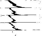
图2为该车库门的侧视图,更具体地说,是在关闭位置时的该车库门相邻的各块板的侧视图;Figure 2 is a side view of the garage door, and more particularly, of the adjacent panels of the garage door in the closed position;
图2A为车库门相邻的板的水平接合情况的放大图;Figure 2A is an enlarged view of the horizontal joint of adjacent panels of a garage door;
图3为处在一个半打开位置的该车库门的侧视图,其中一个车库门板位于水平位置,一个车库门板在一个角度位置,和二个车库门板在垂直方向排成一直线;Figure 3 is a side view of the garage door in a half-open position, wherein one garage door panel is in a horizontal position, one garage door panel is in an angled position, and two garage door panels are vertically aligned;
图3A为当一块车库门板在半打开位置时,车库门相邻的板的接合情况的放大图;Figure 3A is an enlarged view of the engagement of adjacent panels of the garage door when one garage door panel is in the half-open position;
图3B为分段的接头,和该车库门的相邻的水平板沿着其水平边缘的轮廓的等角视图;Figure 3B is a segmented joint, and an isometric view of the profile of adjacent horizontal panels of the garage door along their horizontal edges;
图4为处在一个关闭位置的该车库门的后部视图,它表示该门的内表面,以及该车库门相邻的板的水平取向;Figure 4 is a rear view of the garage door in a closed position showing the interior surface of the door and the horizontal orientation of adjacent panels of the garage door;
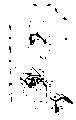
图5为将在关闭位置时的该车库门相邻的板连接起来的铰链组件的放大的等角视图;Figure 5 is an enlarged isometric view of the hinge assembly connecting adjacent panels of the garage door in the closed position;
图6为表示根据本发明制造的一个车库门的第二个实施例的背面或内部的等角视图;Figure 6 is an isometric view showing the rear or interior of a second embodiment of a garage door made in accordance with the present invention;
图7为在该车库门的水平板的相对的侧边缘的中间的图6所示的铰链组件的放大的等角视图;Figure 7 is an enlarged isometric view of the hinge assembly shown in Figure 6 intermediate the opposite side edges of the horizontal panel of the garage door;
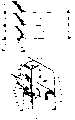
图8为图6所示的实施例中的安装在该车库门板边缘上的铰链组件结构的分解的等角视图;Figure 8 is an exploded isometric view of the hinge assembly structure mounted on the edge of the garage door panel in the embodiment shown in Figure 6;
图8A为图6所示的实施例的安装在该门的板边缘上的铰链组件结构的放大的等角视图;Figure 8A is an enlarged isometric view of the hinge assembly structure of the embodiment shown in Figure 6 mounted on the panel edge of the door;
图9为图6所示的车库门的板的底部水平边缘的截面图;9 is a cross-sectional view of the bottom horizontal edge of the panel of the garage door shown in FIG. 6;
图9A为图6所示的车库门的底部边缘和滚子的透视图;9A is a perspective view of the bottom edge and rollers of the garage door shown in FIG. 6;
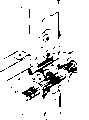
图10为用于一块夹层板的本发明的第三个实施例的横截面的侧视图;Figure 10 is a side view in cross section of a third embodiment of the invention for a sandwich panel;
图10A为用侧剖视图表示的图10所示的该夹层板结构的车库门的多个运动位置顺序;Fig. 10A is a plurality of movement position sequences of the garage door of the sandwich panel structure shown in Fig. 10 represented by a side sectional view;
图10B为图10A所示的铰链组件的放大的截面图;Figure 10B is an enlarged cross-sectional view of the hinge assembly shown in Figure 10A;
图11为图10所示的车库门的相邻的板之间的铰链连接的放大的横截面图;11 is an enlarged cross-sectional view of the hinge connection between adjacent panels of the garage door shown in FIG. 10;
图12为图10所示的车库门的下部水平板的下边缘的放大的横截面图;Figure 12 is an enlarged cross-sectional view of the lower edge of the lower horizontal panel of the garage door shown in Figure 10;
图13为图10所示的车库门的顶部板的顶部边缘的放大的横截面图。13 is an enlarged cross-sectional view of the top edge of the top panel of the garage door shown in FIG. 10 .
为了更好地理解本发明,可参考下面结合所附权利要求书和附图所作的详细说明。简要地说,本发明可防止人的手指或直径在3~5毫米范围内的类似物体插入下述的间隙中:(a)相邻和铰链连接的车库门板在水平方向的前面之间的间隙,(b)相邻和用铰链连接的车库门板在水平方向的后面之间的间隙,和(c)水平方向上,铰链叶片和该车库门相邻的板的相邻结构支承件之间的间隙。因此,本发明的车库门可以在该门的工作过程中防止人的手指被夹住。For a better understanding of the present invention, reference may be made to the following detailed description in conjunction with the appended claims and accompanying drawings. Briefly stated, the present invention prevents the insertion of a human finger or similar object in the range of 3 to 5 mm in diameter into the following gaps: (a) the gap between the horizontal fronts of adjacent and hinged garage door panels , (b) the clearance between adjacent and hinged garage door panels at the horizontal rear, and (c) the horizontal clearance between the hinge blade and the adjacent structural support of the adjacent panel of the garage door gap. Therefore, the garage door of the present invention can prevent a person's fingers from being pinched during the operation of the door.
图1~图5表示第一个实施例,图6表示第二个实施例,图10~图13表示第三个实施例。1 to 5 show a first embodiment, FIG. 6 shows a second embodiment, and FIGS. 10 to 13 show a third embodiment.
参见图1,在本发明的第一个优选实施例中,车库门12包括多块在水平方向的车库门板14,16,18,20。一般,该车库门板14,16,18,20为长方形的,并可用铝、钢、不锈钢或其他适当的车库门材料制成。这些车库门板带有薄的金属表皮,如图2所示。该相邻的板的水平相邻的边缘由铰链连接。具体地说,该铰链连接形成了围绕构成该车库门的板的背面上的一根轴,或邻近该背面的一根轴的铰链连接。即是说,一般,该车库门板的厚度为几英寸。一般,该车库门由金属板制成,金属板的背面可带有或不带有泡沫材料。该板可以包括加强肋,或该板可具有一个泡沫材料制的芯子结构。Referring to FIG. 1, in a first preferred embodiment of the present invention, a
如果(例如)该板的水平边缘为平直的、平面形的和与该板的前面和背面横向相交的,则该板的厚度形成一些可能成为夹手地点的水平边缘。为了减少夹手的地点,先前技术的专利(例如,美国专利5002114号和美国专利3941180号)提出了改进车库门板的前边缘和后边缘的方法。然而,先前技术的专利和结构并不一定能消除所有的夹手地点,特别是由该车库门板形成的该门背面的一些夹手地点。因此,本发明的第一个实施例的板沿着其背面用铰链连接,并且,这些板都形成或具有一定厚度。If, for example, the horizontal edges of the panel are straight, planar and transversely intersecting the front and back of the panel, the thickness of the panel creates horizontal edges that may become pinch sites. In order to reduce pinch locations, prior art patents (eg, US Patent No. 5,002,114 and US Patent No. 3,941,180) propose methods of modifying the front and rear edges of garage door panels. However, prior art patents and constructions do not necessarily eliminate all pinch points, particularly some on the back of the door formed by the garage door panel. Thus, the panels of the first embodiment of the present invention are hinged along their backs, and the panels are formed or have a certain thickness.
参见图2,当在关闭状态时,该车库门的板14,16,18,20都在同一个垂直平面上,并形成一个比较平直的外表面。如图3的截面侧视图所示,该板14,16,18,20沿着其相邻的水平边缘的内表面或背面,用铰链连接在一起。每一块板的二个侧面都包括有一些突出出来的滚子(例如,图4中的滚子17,19),这些滚子在该车库门的开口的每一侧上的一根轨道(图3中的21)上运行。该轨道沿着该门的开口有一个垂直的滑道23(run),该滑道23由一个弓形部分25与一个位于上面的水平滑道27A连接。一般,该滚子17,19与相邻的水平板之间的铰链连接同轴,或几乎同轴。这样,当该由多块板构成的门打开时,这些板(例如,板14,16)围绕着上述连接铰链的销子被铰链连接起来(下面将作更详细的说明)。当这些板沿着该轨道21运动,并互相铰接时,该板的相对的水平边缘也彼此相对运动。该车库门板边缘和连接铰链的设计可以防止不论相邻的板的铰接位置在那里,在该板的边缘之间不出现大的间隙。由于这样的设计,在铰链连接处不可能将直径比5毫米大的一根试验棒插入该门的任何一侧(前侧或后侧)。Referring to Fig. 2, when in the closed position, the
特别是,该车库门的板的相邻的水平边缘的相对的凸起轮廓和凹入轮廓几乎是相同的,并且互相叠置在一起。然而,凹入轮廓22形成一个可容纳凸起轮廓24的凹窝,并且可在一个广大的铰链连接范围内消除间隙。这样,该上部或凹入轮廓22包括一个凹形(一般为弧形)的,从上部板16的前表面29开始的部分26。这个弧形部分26在每一块上部板16的后侧其轮廓变为基本上为平直的平面形水平部分28。该平直部分28的厚度为该板16厚度(板的前表面至其背面的尺寸)的10~25%。如果希望的话,可以取消该平直部分28,而使上述弧形形状继续延伸。In particular, the opposing convex and concave profiles of adjacent horizontal edges of the garage door panels are nearly identical and superimposed on each other. However, the
一个径向滑道32与上述平直部分28连接,或沿着径向方向向着作为该上部板16和板18的枢转轴或回转轴55的一个铰链销子70从该平直部分28延伸出来。该径向滑道32的终端为一个向着该上部板16的前面延伸的弦杆滑道,或压折部分30。该弦杆滑道30与该上部板16的前表面29和该板16的后端径向滑道32垂直。尽管每一个轮廓22,24的轮廓形状基本上相同,但上述凹入部分的轮廓22的线性延伸或其长度超过上述凸起部分轮廓24的长度。一般,该凸起轮廓24的弧形部分34与该凹入轮廓22的孤形部分26相同,其中心都在轴55上。平直部分36在该上述凹入轮廓22的平直部分28的下面,并比平直部分28短些。一般,该凹入轮廓和凸起轮廓的弧形部分26,34的曲率半径的中心均在上述铰链销子70的轴线55上,并且该二个弧形部分彼此隔开一定距离。当在该车库门打开过程中,上述车库门的板16,18铰接时,这种轮廓可以保证从该门的前侧看的,上述板16,18之间的间隙最小(在3~5毫米范围内)。A
上述板18的凸起轮廓24的后侧的形状与先前已知的结构有很大不同,因为该凸起轮廓24的后部包括一个径向滑道40。该径向滑道40可以与上述板16的径向滑道32平行,并且基本上是从铰链销子54的轴线55向外伸展出去的。然而,为了保证在该铰链销子54附近的间隙最小,每一个径向滑道32,40分别包括一个压折部分或弦杆滑道30,38。当上述板16,18在垂直位置,或在同一个平面上时,一般,该弦杆滑道30,38是互相平行,并稍微隔开一点的。上述弦杆滑道30、38的间隔大小和长度由上述板16,18铰接时形成的通道决定。即是说,上述上部板16的压折滑道30描绘出一个弧形的通道轮廓,并且当相邻的板铰接在一起时,可以保持上述弦杆滑道30的端部和上述下部板18的凸起轮廓的弦杆通道38之间的间隙最小。当考虑上述径向滑道32,40的间隙大小和长度,及上述铰链销子轴线55的位置时,可使上述板后部的间隙最小的每一个弦杆滑道30,38的长度可根据经验决定。The shape of the rear side of the raised
现参照图2A,图中表示了车库门板16和18。在该门的关闭位置或完全打开位置下,该车库门板16有一个作成一定形状的成形底部凹入部分22,而该门的板18具有一个作成一定形状的成形顶部凸起部分24。该车库门的每一块板14,16,18,20都包括一个成形的底部凹入部分22,和一个成形的顶部凸起部分24。在使用中,该车库门的第一块板16的上述底部凹入部分22与该车库门的第二块板18的顶部凸起部分24配合,以便当该二块板16,18沿着上述该车库门的侧面轨道运动时,不论该二块板16,18的相对铰接情况如何,都可防止手指插入该二块板16,18之间的间隙中,如图3和图3A所示。Referring now to Figure 2A,
这样,如图3A所示,该车库门的二块板16和18处在铰接状态,上述径向滑道32,40之间形成一个夹角44。该车库门的板16的底部凹入部分22的横截面形状包括:一个曲线部分26,一个水平直线部分28和一个垂直直线部分32。该曲线部分26与该车库门的板16的前表面29连接,并在该曲线部分26和该前表面29之间形成一个圆形的拐角27。该曲线部分26可以形成一个相对于该底部凹入部分22的中间凹进去的圆弧,或可以作成多个连接在一起的多边形部分的形式。Thus, as shown in FIG. 3A , the two
该曲线部分26与该水平直线部分28连接。该水平直线部分28大致上在该车库门的板16的前表面29的横向,或与该前表面29垂直。该水平直线部分28与上述的垂直直线部分32成直角连接,并且该垂直直线部分32大致与该车库门的板16的前表面29平行。该垂直直线部分或滑道32与在该车库门的板16的前表面29的横向的水平直线部分或弦杆滑道30形成一个直角。该水平直线部分30具有一个可由卷曲该水平直线部分30的末端而形成的圆形末端或舌片。The curved portion 26 is connected to the horizontal
同样,该车库门的板18的凸起部分24的横截面形状包括:一个曲线部分34,一个水平直线部分36,一个垂直直线部分40和一个折叠末端38。该曲线部分34向该车库门的板18的平面外面弯曲,并在该车库门的板18的平面和该曲线部分34之间,形成一个过渡部分46。该过渡部分46的尺寸和形状,与上述凹入部分22的圆形拐角27相工作匹配。Likewise, the cross-sectional shape of the raised
再参见图2A,在关闭位置时,该车库门的板16和18在该车库门的板16的圆形拐角27与上述车库门的板18的过渡部分46接合的点上,互相接触。沿着该板16和18的后部,在上述弦杆滑道30和40之间没有间隙。这样,当该门的板在关闭位置时,在二块板16和18之间没有间隙。因此,当该车库门的板在关闭(共面)位置时,人的手指不会被夹住。Referring again to FIG. 2A , in the closed position, the
该车库门的每一块板14,16,18的重量均由一个结构零件支承。可以使用任何能够支承必要负荷的结构零件;然而,在图1至图5的实施例中,使用了基本上为U-字形的带槽的零件50。每一个U-字形带槽零件50均利用铆钉52或其他适当的紧固件固定在上部板16的前表面29上,并且在垂直方向与相邻的板上的其他U-字形带槽零件50排成一直线。另外,该车库门的每一块板都包括多个U-字形的带槽零件50。这样,如图4所示,该车库门的每一块板都设有二个U-字形的带槽零件50。这些U-字形的带槽零件50放置在靠近该车库门板每一端的地方,并在垂直方向上排列成一直线。为了使该车库门的每一块板有足够的强度和容易装配,最好每一个U-字形带槽零件50由方形管子制成,或者是用平的板材,或其他技术已知的方法制成。每一个U-字形的带槽零件50具有一个顶端51和一个底端53。一般,该顶端51的形状是与该门的板的顶部凸起部分24的轮廓匹配的。该顶端51还包括由一个凸面50C连接的互相隔开和平行的二个肋50A,50B。在每一块板的顶端都有二个彼此相对的、在水平方向排列成一直线的、通过该二个肋50A,50B的孔54。The weight of each
又参见图5,一个铰链叶片60固定在该在垂直方向排列成一直线的U-字形带槽零件50上。该铰链叶片60的一个固定部分62与该U-字形的带槽零件50的底端53对齐,以便可卸下地将该铰链叶片60固定在该U-字形带槽零件50的凸面50C上。采用紧固件64可卸下地将该铰链叶片60固定在该U-字形带槽零件50上。该紧固件64可以是螺钉、铆钉或任何其他紧固装置。Referring again to FIG. 5, a
该铰链叶片60具有一个从上述固定部分62的平面伸出的成一定角度的铰链部分66。该一定角度的铰链部分66与上述U-字形带槽零件50的顶端配合,可防止人的手指放在上述肋50A和50B之间时被夹住。该成一定角度的铰链部分66形成一个沿着该成一定角度的铰链部分66的宽度水平延伸的基本上为圆柱形的孔57。该成一定角度的铰链部分66上的圆柱形孔57与上述U-字形带槽零件50的顶端51上的二个彼此相对的在水平方向上排列成一直线的孔54沿水平方向对准。The
一个铰链销子70穿过该成一定角度的铰链部分66的圆柱形孔57,和上述二个彼此相对的、在水平方向排列成一直线的孔54。该铰链销子70将固定在该车库门的板18上的上述U-字形带槽零件50和该成一定角度的铰链部分66工作连接起来。该铰链叶片60的成一定角度的铰链部分66再将该铰链叶片60与固定在该车库门的板16上的上述U-字形带槽零件50连接起来。这样,当该车库门12从关闭状态过渡到打开状态时,该铰链销子70可取下地使该门的板18与板16连接,使该二块板18和16可围绕着该铰链销子70彼此相对转动。如图5所示,该铰链叶片60和铰链销子70放置在该垂直方向上排列成一直线的U-字形带槽零件的二个相邻的肋50A,50B之间;并且将该车库门的每一个相邻的板连接。A
图6表示在本发明的第二个或另一个实施例中所述的一个车库门的水平铰链连接结构。由于该相邻的水平板之间的连接与先前在图2A和图3A中所述的连接相同,因此,图6所示的板的形状和结构基本上与图1~图5所示的板的形状和结构相同。但是,也有其他一些稍许不同的特点,特别是用于将相邻的多块水平板连接在一起的铰链的结构稍有不同。在图1~图5的实施例中,采用一个单一的铰链叶片与该U-字形带槽零件50的二个加强肋50A,50B组合;而在图6所示的实施例中,该铰链由二个叶片构成,每一个铰链叶片分别与和相邻的水平板相关的加强肋连接。Fig. 6 shows the horizontal hinged structure of a garage door in a second or alternative embodiment of the present invention. Since the connection between the adjacent horizontal plates is the same as previously described in Figures 2A and 3A, the shape and structure of the plates shown in Figure 6 are substantially the same as those shown in Figures 1 to 5. same shape and structure. However, there are other slightly different features, in particular a slightly different configuration of the hinges used to connect adjacent horizontal plates together. In the embodiment of Fig. 1~Fig. 5, adopt a single hinge blade to combine with two reinforcing
现参见图6,图中所示的车库门由四块水平板90、92、94和96组成。这些板安装成可沿着由彼此相对的二条平行轨道98和100形成的通道运动。每一条轨道98和100包括一个垂直滑道102,一个过渡或弧形滑道104,和一个基本上为水平的滑道106。该垂直滑道102用于保持该车库门在关闭状态,如图6所示。该弧形滑道104用于使该门过渡到打开位置。该水平滑道106用于保持该门在完全打开的位置。上述板90、92、94、96利用铰链108和110互相连接在一起。铰链108装在该车库门的边缘上,而铰链110则用于在该门边缘中间的板的连接。如图6所示,沿着每一块板90、92、94和96的相对的边缘,作有加强肋或槽112。在每一块板90、92、94和96上还带有或固定着一些中间或中心加强肋或槽114。Referring now to FIG. 6, the garage door is shown comprised of four
图7较详细地表示了中间铰链组件的结构。该铰链组件包括上述铰链110,和固定在相邻的板(例如,板90和92)上的、排列在一直线上的上述中间肋条114。每一个中间槽或肋114包括二个互相平行和彼此隔开一定距离的侧向肋116和118。该侧向肋116和118由一个凸面部分120连接。利用铆接或其他方法,将该侧面肋116和118固定在该车库门板90和92上。如上所述,该板90和92的水平边缘的形状与图2A和图3A所示的形状基本上相同。然而,该铰链110为具有二个铰链叶片的铰链。该铰链110的上叶片122,基本上与先前所述的铰链叶片60相同,而其下叶片124则设计成具有由一个凸面部分130连接的侧面法兰126和128。该法兰126和128紧密地安装在上述中间肋114的二个侧向肋116和118上,而上述铰链下叶片124则利用紧固件132,紧密地固定在该中间肋114上。上述二个分开的铰链叶片122和124,利用一个铰链销子136连接在一起。Figure 7 shows the structure of the intermediate hinge assembly in more detail. The hinge assembly includes the above-mentioned
下面参见图8和图8A,图中表示了该车库门的边缘槽或边缘肋112,及其相关铰链的结构。这些边缘槽或边缘肋112的结构可允许将该肋112固定在该车库门的板90和92的边缘上,并且具有一系列用于容纳铰链140的紧固件的孔或通道139。这样,该孔139设计成可容纳将该铰链140固定在相邻的板90、92的边缘肋112上的紧固件142。该铰链140包括其形状基本上与上述中心铰链叶片122的形状相同的一个上叶片144。该铰链140的下叶片146的形状有所区别或不同。该下叶片包括一个宽大的中心叶片零件148,和垂直地向外延伸的、带有作在其上的带键槽的孔154和156的二个彼此相对的法兰150和152。该中心叶片零件148的终端有卷曲部分158和160,这些卷曲部分与一个铰链销子(没有示出)结合,可使该中心叶片零件148与该上叶片144连接。另外,利用紧固件142将该中心叶片零件148与上述边缘槽或边缘肋112连接。一个成形轨道滚子162安装在一根成形轴或杆164上;该成形杆164穿过上述安装孔154和156,并支承在该二个孔中。因此,上述铰链140与上述成形滚子162和相应的成形轴或杆164结合,将该车库门支承在上述轨道98上。应当指出,该铰链140的形状与先前所述的铰链是一致的,使上述卷曲部分158和160可装入上述边缘肋或边缘槽112侧边之间的空间中,以避免出现任何夹手的地点。Referring now to Figures 8 and 8A, there is shown the configuration of the garage door edge groove or
图9表示图6或图1所示的车库门的一块水平板的底部所带的下部挡风(雨)的密封(weather seal)的结构的一个例子。由该车库门板的金属板表皮制成的所谓凹入轮廓180,可以容纳一个预先作出的铝的挤压件182。该铝挤压件182具有兼容的,或匹配的形状,可以装在该凹入轮廓180内,以便利用紧固装置(例如,紧固装置184)将该挤压件固定。一个挠性的橡胶密封186装在该挤压件182中形成的槽188中,以形成一个挡风(雨)的密封。Fig. 9 shows an example of the structure of the lower part of the windshield (rain) seal (weather seal) that is carried at the bottom of a horizontal plate of the garage door shown in Fig. 6 or Fig. 1. A so-called concave profile 180 made from the sheet metal skin of the garage door accommodates a pre-fabricated aluminum extrusion 182 . The aluminum extrusion 182 has a compatible, or matching, shape and may fit within the concave profile 180 to secure the extrusion with fastening means (eg, fastening means 184). A flexible rubber seal 186 fits in a groove 188 formed in the extrusion 182 to form a wind (and rain) seal.
图10~图13表示本发明的车库门结构的第三个实施例。图10为构成这个第三个实施例的板的横截面的侧视图。一般,将该第三个实施例描述成一种夹层板的结构。即是说,参见图10,该车库门是由多块板200,202等组成的。每一块都具有一个(例如)用金属板制成的外壳表皮。表皮206用于形成带有作成一定形状的水平边缘的前表面208和背面210。一般,该二个表面208和210之间的区域充满可膨胀的聚苯乙烯材料;该聚苯乙烯材料粘接在由金属板制成的上述表皮的内部。上述车库门的板200和202之间的水平连接处的凸起轮廓和凹入轮廓的形状,基本上与先前所述的凸起轮廓和凹入轮廓的形状相同。然而,在图10~图13的实施例中,该铰链不是与垂直的金属肋连接,而是固定在金属表皮上;更具体地说,是固定在该金属表皮的内表面210上。这样,如图11所示,铰链包括固定在该表皮或背面210上的一个上叶片212。该上叶片还包括一块背面平板214。一块下叶片216与该车库门的下部的板200固定在一起;更具体地说,与该板的表皮背面210固定在一起。一个铰链销子218将该二个叶片212和216连接在一起。该下部板200还包括一个作成一定形状或成形的凹窝220,该铰链销子218和上述二个铰链叶片212与216的相应部分装在该凹窝中。图8所示那种形式的滚子,按照先前所述的方式,沿着该车库门板的相对的边缘,与铰链216配合。图10A表示相邻二块板200和202的铰接情况。10 to 13 show a third embodiment of the garage door structure of the present invention. Figure 10 is a side view of a cross-section of the plate constituting this third embodiment. In general, the third embodiment is described as a sandwich panel construction. That is, referring to Fig. 10, the garage door is formed from a plurality of
再参见图12,与该车库门的底部相关的,或更具体地说,与该车库门板200的底部相关的挡风(雨)密封与先前所述的挡风(雨)密封相同。挤压件222装在该板200的上述凹入轮廓中。一个挠性密封装入在该挤压件222中形成的互相隔开的槽224和226中,用于容纳一个挠性的橡胶密封228。Referring again to FIG. 12, the wind (rain) seal associated with the bottom of the garage door, or more specifically, the bottom of the
图13表示沿着形成图10的实施例的车库门的顶部板的顶部边缘的结构。该顶部边缘的凸起形状不与任何相邻的板互相配合。一个滚子242的安装平板240以其辅助的背面平板244固定在上述表皮的背面210上。图10,11和12的结构是与该车库门的边缘有关的结构。这种车库门中间部分的铰链的滚子附件可以省去。FIG. 13 shows the structure along the top edge of the top panel forming the garage door of the embodiment of FIG. 10 . The raised shape of the top edge does not interfit with any adjacent panels. A mounting
重要的问题是,本发明的每一个实施例包括沿着该车库门的各块板的水平边缘的一种独特的轮廓。该轮廓可包括在只具有前端金属板和加强肋的一种车库门的板中。这种结构还可以使用另外的一些铰链结构。一种夹层板也可以包括上述的水平边缘的形状和轮廓。在每一种情况下,一般该叠置在上面的轮廓的前端为弧形,而其后端则包括一个向内伸出的弦杆部分。当该车库门的二块板绕支轴转动时,该弦杆部分可使上述板之间的连接处的凹入轮廓和凸起轮廓的相应弦杆部分之间的间隙保持最小。一般,上述弦杆部分在上述铰链销子的轴线上面伸出。It is important to note that each embodiment of the present invention includes a unique profile along the horizontal edges of the panels of the garage door. The profile may be included in a panel of a garage door having only a front metal panel and stiffening ribs. This structure can also use other hinge structures. A sandwich panel may also include the shapes and profiles of the horizontal edges described above. In each case, generally the overlying profile is curved at its front end and includes an inwardly projecting chord portion at its rear end. As the two panels of the garage door are pivoted, the chord portion minimizes the gap between the corresponding chord portions of the concave and convex profiles at the junction between the panels. Typically, said chord portion projects above the axis of said hinge pin.
在上述说明中,本发明是结合特定的示例性实施例进行说明的。显然,只要不偏离本发明的精神和范围,本领域技术人员可以进行各种利用本发明原理的改变,改进或作出其他实施例。因此,本说明书和附图仅仅是示例性的,而不是限制性的。因此,本发明仅受所附权利要求书的限制。In the foregoing specification, the invention has been described in connection with specific exemplary embodiments. Apparently, as long as the spirit and scope of the present invention are not deviated, those skilled in the art can make various changes, improvements or other embodiments utilizing the principles of the present invention. Accordingly, the specification and drawings are illustrative only, and not restrictive. Accordingly, the invention is limited only by the appended claims.
Claims (16)
Translated fromChineseApplications Claiming Priority (2)
| Application Number | Priority Date | Filing Date | Title |
|---|---|---|---|
| US08/832,434 | 1997-04-03 | ||
| US08/832,434US5782283A (en) | 1997-04-03 | 1997-04-03 | Garage door construction |
Publications (2)
| Publication Number | Publication Date |
|---|---|
| CN1255957Atrue CN1255957A (en) | 2000-06-07 |
| CN1119494C CN1119494C (en) | 2003-08-27 |
Family
ID=25261638
Family Applications (1)
| Application Number | Title | Priority Date | Filing Date |
|---|---|---|---|
| CN98805025AExpired - Fee RelatedCN1119494C (en) | 1997-04-03 | 1998-03-25 | Garage door construction |
Country Status (12)
| Country | Link |
|---|---|
| US (1) | US5782283A (en) |
| EP (2) | EP0985079B1 (en) |
| CN (1) | CN1119494C (en) |
| AT (1) | ATE240449T1 (en) |
| AU (1) | AU737876B2 (en) |
| CZ (1) | CZ298045B6 (en) |
| DE (1) | DE69814625T2 (en) |
| ES (1) | ES2198050T3 (en) |
| HU (1) | HU223211B1 (en) |
| SI (1) | SI20082B (en) |
| TR (1) | TR199902661T2 (en) |
| WO (2) | WO1998044231A1 (en) |
Cited By (1)
| Publication number | Priority date | Publication date | Assignee | Title |
|---|---|---|---|---|
| CN103850589A (en)* | 2012-12-06 | 2014-06-11 | 家居安全组有限公司 | Multi-leaf closing system |
Families Citing this family (53)
| Publication number | Priority date | Publication date | Assignee | Title |
|---|---|---|---|---|
| US5992497A (en)* | 1997-04-25 | 1999-11-30 | Clopay Building Products Company, Inc. | Slip and lock connection system |
| US6076590A (en)* | 1997-12-01 | 2000-06-20 | Garage Door Group, Inc. | Segmented garage door and hinges |
| US5921307A (en)* | 1997-12-01 | 1999-07-13 | Garage Door Group, Inc. | Garage door hinge |
| US6772814B2 (en) | 1998-01-09 | 2004-08-10 | Clopay Building Products R&D Company, Inc. | Combined weather seal, light block and wear insert for overhead door panel |
| US6006817A (en)* | 1998-01-09 | 1999-12-28 | Clopay Building Products Company | Overhead door, panel and hinge assembly |
| US6082046A (en)* | 1998-02-25 | 2000-07-04 | Simmons; Kevin A. | Overhead door sensor mounting bracket |
| AUPP269298A0 (en)* | 1998-03-31 | 1998-04-23 | Clyde Industries Limited | Sectional overhead door with anti-pinch hinge |
| AU734088B2 (en)* | 1998-03-31 | 2001-05-31 | B&D Australia Pty Ltd | Hinge assembly for a sectional door |
| US6098697A (en)* | 1998-06-12 | 2000-08-08 | Overhead Door Corporation | Sectional door with pinch resistant hinge between door sections |
| CA2278262A1 (en) | 1998-07-20 | 2000-01-20 | Clark Craig | Hingeless, parallel storing, sectional aperture covering |
| US6212826B1 (en) | 1999-06-30 | 2001-04-10 | Midwest Industrial Door, Inc. | Reciprocating barrier assembly |
| US6363993B1 (en) | 2000-02-28 | 2002-04-02 | Anthony George Aquilina | Pivoting bracket for connecting articulated door panels |
| US6328091B1 (en) | 2000-05-15 | 2001-12-11 | Overhead Door Corporation | Upward acting sectional door with pinch resistant edge profile between door panels |
| US6941510B1 (en) | 2000-06-06 | 2005-09-06 | Groove Networks, Inc. | Method and apparatus for efficient management of XML documents |
| US6672362B1 (en)* | 2000-11-10 | 2004-01-06 | Wayne-Dalton Corp. | Upward acting sectional door |
| US6578619B2 (en) | 2001-05-21 | 2003-06-17 | Raynor Garage Doors | Overhead garage door |
| US6527036B1 (en) | 2001-06-15 | 2003-03-04 | Thomas M. Welsh | Pinch resistant hinge and joint construction for upward acting sectional doors |
| US6629387B2 (en)* | 2001-07-23 | 2003-10-07 | Overhead Door Corporation | Sectional upward acting door and method of assembly |
| ITUD20020021A1 (en)* | 2002-01-31 | 2003-07-31 | Breda Sistemi Ind Spa | POSITIONERS FOR ELEMENTS FOR DOORS WITH HORIZONTAL SECTIONS |
| US7857032B2 (en)* | 2002-03-18 | 2010-12-28 | Frenchporte Ip, L.L.C. | Overhead garage door |
| US6951237B2 (en)* | 2002-04-24 | 2005-10-04 | Wayne-Dalton Corp. | Sectional door system |
| US7055573B2 (en)* | 2002-04-25 | 2006-06-06 | Martin Door Manufacturing | Systems and methods for reducing gap space between door sections |
| US6837296B2 (en) | 2002-11-15 | 2005-01-04 | Midwest Industrial Door, Inc. | Safety barrier assembly |
| US6843300B2 (en) | 2003-03-21 | 2005-01-18 | Wayne-Dalton Corp. | Sectional door with self-aligning hinges and method of assembly |
| US7763341B2 (en) | 2004-01-23 | 2010-07-27 | Century-Board Usa, Llc | Filled polymer composite and synthetic building material compositions |
| US7211206B2 (en)* | 2004-01-23 | 2007-05-01 | Century-Board Usa Llc | Continuous forming system utilizing up to six endless belts |
| EP1776216A4 (en) | 2004-06-24 | 2009-04-08 | Century Board Usa Llc | INSTALLATION FOR CONTINUOUS PRODUCTION OF THREE DIMENSIONAL FOAM ARTICLES |
| US7201207B2 (en)* | 2004-09-24 | 2007-04-10 | Clopay Building Products R&D Company, Inc. | Overhead sectional door, hinge and associated method |
| US7866368B2 (en)* | 2005-03-11 | 2011-01-11 | Raynor Garage Doors | Garage door panel construction and hardware |
| EP1722065A1 (en)* | 2005-05-09 | 2006-11-15 | Novoferm France | Panel of hollow reinforcement beams |
| US20070056694A1 (en)* | 2005-08-24 | 2007-03-15 | Mullet Willis J | Wind resistant movable barrier |
| US7730928B2 (en)* | 2006-03-16 | 2010-06-08 | Clopay Building Products Co., Inc. | Overhead sectional door, hinge and stile assembly |
| US8299136B2 (en) | 2006-03-24 | 2012-10-30 | Century-Board Usa, Llc | Polyurethane composite materials |
| US20070283525A1 (en)* | 2006-04-27 | 2007-12-13 | Canimex Inc. | Extension spring door kit |
| US7575037B2 (en)* | 2006-05-12 | 2009-08-18 | Jorgensen N Valde V | Overhead bi-fold latching door |
| JP4885665B2 (en) | 2006-09-21 | 2012-02-29 | セイコーインスツル株式会社 | Pedometer |
| CA2592895C (en)* | 2007-06-27 | 2014-04-15 | Gia Loc Huynh | Breakaway door panel system |
| US20100287727A1 (en)* | 2009-05-13 | 2010-11-18 | Suderman Jim R | Overhead Bi-Fold Door Assembly |
| US9481759B2 (en) | 2009-08-14 | 2016-11-01 | Boral Ip Holdings Llc | Polyurethanes derived from highly reactive reactants and coal ash |
| US8846776B2 (en) | 2009-08-14 | 2014-09-30 | Boral Ip Holdings Llc | Filled polyurethane composites and methods of making same |
| CA2740523C (en) | 2010-05-26 | 2016-11-08 | Wabash National, L.P. | Overhead door assembly for a storage container |
| US8627872B2 (en) | 2010-11-10 | 2014-01-14 | Raynor Mfg., Co. | Garage door with reinforcing truncated isosceles strut construction and reinforcing strut construction |
| CA2851349C (en) | 2011-10-07 | 2020-01-21 | Russell L. Hill | Inorganic polymer/organic polymer composites and methods of making same |
| WO2014168633A1 (en) | 2013-04-12 | 2014-10-16 | Boral Ip Holdings (Australia) Pty Limited | Composites formed from an absorptive filler and a polyurethane |
| WO2016018226A1 (en) | 2014-07-28 | 2016-02-04 | Crocco Guy | The use of evaporative coolants to manufacture filled polyurethane composites |
| WO2016022103A1 (en) | 2014-08-05 | 2016-02-11 | Amitabha Kumar | Filled polymeric composites including short length fibers |
| US9988512B2 (en) | 2015-01-22 | 2018-06-05 | Boral Ip Holdings (Australia) Pty Limited | Highly filled polyurethane composites |
| US10030126B2 (en) | 2015-06-05 | 2018-07-24 | Boral Ip Holdings (Australia) Pty Limited | Filled polyurethane composites with lightweight fillers |
| US20170267585A1 (en) | 2015-11-12 | 2017-09-21 | Amitabha Kumar | Filled polyurethane composites with size-graded fillers |
| BE1024991B1 (en) | 2017-02-15 | 2018-09-18 | Renson Sunprotection Projects Nv | SECTIONAL PORT |
| US10794112B2 (en) | 2018-06-22 | 2020-10-06 | Mckeon Rolling Steel Door Co., Inc. | Slatted door with increased impact resistance |
| KR102113880B1 (en)* | 2020-03-09 | 2020-05-21 | 김서연 | Door with finger pinch prevention function |
| US12129708B2 (en) | 2021-06-15 | 2024-10-29 | Mckeon Rolling Steel Door Co., Inc. | Slatted door with increased impact resistance |
Family Cites Families (77)
| Publication number | Priority date | Publication date | Assignee | Title |
|---|---|---|---|---|
| US1888162A (en)* | 1932-11-15 | eklund | ||
| US1530762A (en)* | 1921-08-01 | 1925-03-24 | Dautrick Johnson Mfg Company | Garage door |
| US1724995A (en)* | 1922-11-20 | 1929-08-20 | Ernest R Wilson | Garage door |
| US1621669A (en)* | 1923-12-08 | 1927-03-22 | Clarence G Johnson | Garage door and operating mechanism therefor |
| US1626844A (en)* | 1925-09-08 | 1927-05-03 | Graham Brothers | Finger guard for foldable bus doors |
| US1750042A (en)* | 1928-04-23 | 1930-03-11 | Brooks B Hoover | Carage door |
| US1827433A (en)* | 1929-09-05 | 1931-10-13 | Nathan T Ladenson | Sliding door |
| US1995644A (en)* | 1930-03-03 | 1935-03-26 | Max C Miller | Knitting machine |
| US1994142A (en)* | 1930-04-24 | 1935-03-12 | Yoder Morris Company | Door operating mechanism |
| US1990870A (en)* | 1931-03-26 | 1935-02-12 | Harry G Kelly | Rolling door mechanism |
| US2017012A (en)* | 1932-07-05 | 1935-10-08 | Truscon Steel Co | Door structure |
| US2059833A (en)* | 1935-02-27 | 1936-11-03 | Wilson J G Corp | Automatic safety overhead door closer |
| US2134397A (en)* | 1936-09-28 | 1938-10-25 | Henry B Clark | Overhead door |
| US2099191A (en)* | 1936-10-01 | 1937-11-16 | Overhead Door Corp | Sliding door |
| US2093019A (en)* | 1937-01-23 | 1937-09-14 | Rowe Mfg Company | Overhead door construction |
| US2166746A (en)* | 1937-07-10 | 1939-07-18 | Huck Gerhardt Company Inc | Overhead operating garage door construction |
| US2557716A (en)* | 1945-12-07 | 1951-06-19 | Moynahan Bronze Company | Safety hinge |
| US2641792A (en)* | 1950-01-17 | 1953-06-16 | Noble E Peeler | Hinge guard |
| US2852840A (en)* | 1953-04-22 | 1958-09-23 | Kelsey I Harvey | Method of making metal reinforced plastic bodies |
| US2681480A (en)* | 1953-06-03 | 1954-06-22 | Sr John J Dixon | Finger guard for swinging doors |
| US2694234A (en)* | 1953-06-26 | 1954-11-16 | Stanley Works | Finger guard for swinging doors |
| US2817875A (en)* | 1954-01-18 | 1957-12-31 | Gen Motors Corp | Mold for molding rubber foam latex strips and the like |
| US3000048A (en)* | 1955-03-09 | 1961-09-19 | Morrison Steel Products Inc | Overhead door |
| US2952313A (en)* | 1956-10-04 | 1960-09-13 | Overhead Door Corp | Sectional upwardly acting doors and like closures |
| US2910741A (en)* | 1956-11-02 | 1959-11-03 | George W Houlsby Jr | Safety device for swinging doors |
| US2871932A (en)* | 1957-07-18 | 1959-02-03 | Overhead Door Corp | Upwardly acting doors having tracks inclined relative to the door frame |
| US3104699A (en)* | 1959-08-17 | 1963-09-24 | Frantz Mfg Company | Overhead door construction |
| US3013410A (en)* | 1960-04-11 | 1961-12-19 | Falk Corp | Coupling cover |
| US3198242A (en)* | 1961-09-05 | 1965-08-03 | Overhead Door Corp | Upwardly acting door and seal means therefor |
| US3160200A (en)* | 1961-09-28 | 1964-12-08 | Mckee Door Company | Drive mechanism for overhead doors |
| US3165143A (en)* | 1963-02-04 | 1965-01-12 | Rowe Mfg Co | Door control mechanism |
| US3322586A (en)* | 1963-06-11 | 1967-05-30 | Weyerhaeuser Co | Method and apparatus for joining laminae at the point of convergence of their respective conveyors |
| US3302690A (en)* | 1964-05-04 | 1967-02-07 | Raymond M Hurd | Guard for multiple sectioned doors |
| US3359594A (en)* | 1965-04-02 | 1967-12-26 | Pastoor Beno Johannes | Folding closures |
| US3347305A (en)* | 1965-06-01 | 1967-10-17 | Met L Wood Corp | Door construction |
| US3319697A (en)* | 1965-06-22 | 1967-05-16 | John M Krohn | Garage door guard |
| DE1704841A1 (en)* | 1967-07-27 | 1971-06-03 | Hennecke Gmbh Maschf | Process and device for the continuous production of profiles from foams, in particular based on polyurethane |
| AU426280B2 (en)* | 1968-05-15 | 1972-07-19 | Touma Door Company Pty. Limited | Sliding door |
| US3635277A (en)* | 1969-10-29 | 1972-01-18 | Steiner American Corp | Door control mechanism |
| US3648755A (en)* | 1970-04-27 | 1972-03-14 | United States Steel Corp | Connecting cover strip and hinge for plural panel doors |
| US3740916A (en)* | 1971-03-24 | 1973-06-26 | P Kenaga | Panel construction |
| US3934635A (en)* | 1972-10-17 | 1976-01-27 | Krs Industries, Inc. | Overhead door for a container having a vertical opening such as a truck trailer |
| US3893269A (en)* | 1973-02-20 | 1975-07-08 | United States Gypsum Co | Curbed walls comprising pairs of planar panels and studs therefore |
| US3869269A (en)* | 1973-06-20 | 1975-03-04 | Ppg Industries Inc | Method and apparatus for press shaping heat-softened sheets |
| US3891021A (en)* | 1973-10-01 | 1975-06-24 | Stanley Works | Garage door with rolled overlapping joint for adjacent panels |
| FR2282032A1 (en)* | 1974-08-13 | 1976-03-12 | Ippolito Marceau | SAFETY DEVICE ESPECIALLY FOR DOOR SHEET |
| US3941180A (en)* | 1974-12-30 | 1976-03-02 | Winnebago Industries, Inc. | Sectional door and guard rail assembly |
| US4348164A (en)* | 1976-10-04 | 1982-09-07 | Toyo Rubber Chemical Industrial Corporation | Apparatus for continuous production of a slab of polyurethane foam |
| US4151031A (en)* | 1977-07-05 | 1979-04-24 | General Dynamics Corporation | Apparatus for continuously forming composite shapes |
| US4284118A (en)* | 1978-09-06 | 1981-08-18 | Sergio Ceron | Folding-door comprised of wooden slats and hinges |
| DE2903745C2 (en)* | 1979-02-01 | 1981-03-26 | Greschbach, Manfred, 79336 Herbolzheim | Sliding folding door |
| US4238544A (en)* | 1979-05-16 | 1980-12-09 | Virginia Door Co. | Door panel and manner of making |
| US4339487A (en)* | 1979-05-16 | 1982-07-13 | Mullet Willis J | Door panel and manner of making same |
| US4269253A (en)* | 1979-06-13 | 1981-05-26 | Ziegler Robert J | Garage door and safety guard therefor |
| US4472910A (en)* | 1982-09-29 | 1984-09-25 | Chamnberlain Manufacturing Corporation | Integral device for garage door opener |
| DK211885A (en)* | 1984-06-05 | 1985-12-06 | Effe Elle Spa | FOLDING ROAD SYSTEM |
| US4685266A (en)* | 1985-11-18 | 1987-08-11 | Willis Mullet | Overhead door panel and method of making |
| AT387258B (en)* | 1987-04-28 | 1988-12-27 | Novoferm Stahlbauwerk Kg | CASE BRAKE |
| JPH0618730B2 (en)* | 1987-06-27 | 1994-03-16 | 株式会社ジャムコ | Molding method for plastic composites |
| DE3726699C5 (en)* | 1987-08-11 | 2009-05-28 | Hörmann KG Brockhagen | Sectional |
| US5001862A (en)* | 1987-12-18 | 1991-03-26 | Abraham Albenda | Safety attachment for hinged side of doors |
| AT399910B (en)* | 1988-02-18 | 1995-08-25 | Atlas Ideal Tueren Und Tore Ge | LIFTING GATE |
| US5170832A (en)* | 1988-02-18 | 1992-12-15 | Hugo Wagner | Lift link gate having a plurality of tabular gate elements |
| US4878267A (en)* | 1988-10-11 | 1989-11-07 | Roach James F | Resisting entry of an object into a space between the hinged edge of a door member hingedly attached to a associated jamb member and a surface of the jamb member |
| US5002114A (en)* | 1988-11-25 | 1991-03-26 | Hormann Kg Brockhagen | Overhead door |
| DE3922981A1 (en)* | 1988-11-25 | 1990-05-31 | Hoermann Kg | Vertically sliding door with horizontal panels |
| DE3922995A1 (en)* | 1988-11-25 | 1990-05-31 | Hoermann Kg | Vertically sliding door with horizontal panels |
| EP0370376B2 (en)* | 1988-11-25 | 1998-12-02 | Hörmann KG Brockhagen | Door leaf |
| DE58907176D1 (en)* | 1988-11-25 | 1994-04-14 | Hoermann Kg | Door leaf. |
| AT394416B (en)* | 1989-12-21 | 1992-03-25 | Novoferm Stahlbauwerk Kg | CORNER CONNECTOR FOR FRAME AND THE LIKE |
| CA2006373C (en)* | 1989-12-21 | 1995-03-21 | Hermel Cloutier | Door counterweight system |
| US5036899A (en)* | 1990-08-02 | 1991-08-06 | Mullet Willis J | Panel garage door opening and closing |
| GB2261012A (en)* | 1991-10-31 | 1993-05-05 | Geoffrey Phillip Sankey | Door jamb finger guard |
| DE9206018U1 (en)* | 1992-05-11 | 1993-06-03 | Fa. Walter Teckentrup, 33415 Verl | Sectional door |
| DE4227311C2 (en)* | 1992-08-18 | 1997-05-22 | Erich Doering | Panel for a ceiling or side sectional door |
| AT399199B (en)* | 1993-02-23 | 1995-03-27 | Novoferm Stahlbauwerk Kg | CASTING STRIP FOR METAL DOORS |
| DE9406615U1 (en)* | 1994-04-20 | 1994-08-18 | Günther, Wolfgang, Dipl.-Ing., 35781 Weilburg | Connection of the frame and rung profiles on the sectional door with finger protection |
- 1997
- 1997-04-03USUS08/832,434patent/US5782283A/ennot_activeExpired - Lifetime
- 1998
- 1998-02-23WOPCT/US1998/003410patent/WO1998044231A1/enactiveApplication Filing
- 1998-03-25CZCZ0352699Apatent/CZ298045B6/ennot_activeIP Right Cessation
- 1998-03-25ESES98911997Tpatent/ES2198050T3/ennot_activeExpired - Lifetime
- 1998-03-25AUAU65818/98Apatent/AU737876B2/ennot_activeCeased
- 1998-03-25WOPCT/US1998/005757patent/WO1998044232A1/enactiveIP Right Grant
- 1998-03-25ATAT98911997Tpatent/ATE240449T1/ennot_activeIP Right Cessation
- 1998-03-25EPEP98911997Apatent/EP0985079B1/ennot_activeExpired - Lifetime
- 1998-03-25DEDE69814625Tpatent/DE69814625T2/ennot_activeExpired - Fee Related
- 1998-03-25TRTR1999/02661Tpatent/TR199902661T2/enunknown
- 1998-03-25CNCN98805025Apatent/CN1119494C/ennot_activeExpired - Fee Related
- 1998-03-25EPEP03010720Apatent/EP1336712A1/ennot_activeWithdrawn
- 1998-03-25SISI9820031Apatent/SI20082B/ennot_activeIP Right Cessation
- 1998-03-25HUHU0001244Apatent/HU223211B1/ennot_activeIP Right Cessation
Cited By (1)
| Publication number | Priority date | Publication date | Assignee | Title |
|---|---|---|---|---|
| CN103850589A (en)* | 2012-12-06 | 2014-06-11 | 家居安全组有限公司 | Multi-leaf closing system |
Also Published As
| Publication number | Publication date |
|---|---|
| SI20082A (en) | 2000-04-30 |
| HUP0001244A2 (en) | 2000-08-28 |
| CZ9903526A3 (en) | 2001-06-13 |
| WO1998044232A1 (en) | 1998-10-08 |
| AU6581898A (en) | 1998-10-22 |
| ES2198050T3 (en) | 2004-01-16 |
| HUP0001244A3 (en) | 2000-09-28 |
| DE69814625D1 (en) | 2003-06-18 |
| AU737876B2 (en) | 2001-09-06 |
| DE69814625T2 (en) | 2004-03-25 |
| CN1119494C (en) | 2003-08-27 |
| WO1998044231A1 (en) | 1998-10-08 |
| CZ298045B6 (en) | 2007-06-06 |
| EP0985079B1 (en) | 2003-05-14 |
| EP0985079A4 (en) | 2001-03-28 |
| TR199902661T2 (en) | 2000-01-21 |
| ATE240449T1 (en) | 2003-05-15 |
| EP0985079A1 (en) | 2000-03-15 |
| US5782283A (en) | 1998-07-21 |
| SI20082B (en) | 2002-02-28 |
| HU223211B1 (en) | 2004-03-29 |
| EP1336712A1 (en) | 2003-08-20 |
Similar Documents
| Publication | Publication Date | Title |
|---|---|---|
| CN1119494C (en) | Garage door construction | |
| CN1292141C (en) | hanging garage door | |
| US6363993B1 (en) | Pivoting bracket for connecting articulated door panels | |
| US7730928B2 (en) | Overhead sectional door, hinge and stile assembly | |
| US5913352A (en) | Hinge and improved hinge and panel surface geometry of a multi-panel door assembly | |
| US5809617A (en) | Mounting for movable members | |
| US20100012280A1 (en) | Folding door assembly | |
| GB2184480A (en) | Window hinge | |
| JPH08503275A (en) | Mutual connection member for panel connection | |
| CN110541640A (en) | A wipeable window hinge | |
| EP0471014A1 (en) | Sectional doors and flexible hinge assemblies. | |
| EP1357249A3 (en) | Non-binding sectional door and method of assembly | |
| JP3172348B2 (en) | Window support | |
| US7010833B2 (en) | Slide hinge for spa cover | |
| US20050183834A1 (en) | Hinge assembly | |
| US20050251958A1 (en) | Retractable door double roller support system | |
| AU2003254764B2 (en) | Leaf hinge | |
| CN215169041U (en) | Heavy three-connecting-rod sliding support | |
| AU689177B2 (en) | Mounting for movable members | |
| MXPA97006288A (en) | Coupling unit for pue panels | |
| EP1887179A1 (en) | Gate leaf for a sectional gate | |
| AU2014202316A1 (en) | An articulated joint | |
| JPS6282191A (en) | Window structure | |
| MXPA01004776A (en) | Upward acting sectional door with pinch resistant edge profile between door panels |
Legal Events
| Date | Code | Title | Description |
|---|---|---|---|
| C06 | Publication | ||
| PB01 | Publication | ||
| C10 | Entry into substantive examination | ||
| SE01 | Entry into force of request for substantive examination | ||
| C14 | Grant of patent or utility model | ||
| GR01 | Patent grant | ||
| C19 | Lapse of patent right due to non-payment of the annual fee | ||
| CF01 | Termination of patent right due to non-payment of annual fee |