CN1255646C - Vehicular headlamp - Google Patents
Vehicular headlampDownload PDFInfo
- Publication number
- CN1255646C CN1255646CCNB200310113810XACN200310113810ACN1255646CCN 1255646 CCN1255646 CCN 1255646CCN B200310113810X ACNB200310113810X ACN B200310113810XACN 200310113810 ACN200310113810 ACN 200310113810ACN 1255646 CCN1255646 CCN 1255646C
- Authority
- CN
- China
- Prior art keywords
- light
- emitting element
- emitting
- light source
- chip
- Prior art date
- Legal status (The legal status is an assumption and is not a legal conclusion. Google has not performed a legal analysis and makes no representation as to the accuracy of the status listed.)
- Expired - Fee Related
Links
- 230000003287optical effectEffects0.000claimsabstractdescription73
- 238000009826distributionMethods0.000claimsabstractdescription59
- 239000004065semiconductorSubstances0.000claimsdescription7
- 230000002194synthesizing effectEffects0.000claims1
- 238000010586diagramMethods0.000description17
- 238000000034methodMethods0.000description10
- OAICVXFJPJFONN-UHFFFAOYSA-NPhosphorusChemical compound[P]OAICVXFJPJFONN-UHFFFAOYSA-N0.000description9
- 230000001678irradiating effectEffects0.000description6
- 238000009792diffusion processMethods0.000description5
- 238000005315distribution functionMethods0.000description5
- 239000000463materialSubstances0.000description5
- 230000000694effectsEffects0.000description4
- 230000015572biosynthetic processEffects0.000description3
- 239000011347resinSubstances0.000description3
- 229920005989resinPolymers0.000description3
- 239000000470constituentSubstances0.000description2
- 238000004519manufacturing processMethods0.000description2
- 238000004088simulationMethods0.000description2
- 239000000758substrateSubstances0.000description2
- 230000009471actionEffects0.000description1
- 230000002411adverseEffects0.000description1
- 230000000903blocking effectEffects0.000description1
- 230000008859changeEffects0.000description1
- 150000001875compoundsChemical class0.000description1
- 230000005684electric fieldEffects0.000description1
- 238000004070electrodepositionMethods0.000description1
- 239000011159matrix materialSubstances0.000description1
- 230000002093peripheral effectEffects0.000description1
- 230000005855radiationEffects0.000description1
- 230000009467reductionEffects0.000description1
- 239000012780transparent materialSubstances0.000description1
Images


Classifications
- F—MECHANICAL ENGINEERING; LIGHTING; HEATING; WEAPONS; BLASTING
- F21—LIGHTING
- F21S—NON-PORTABLE LIGHTING DEVICES; SYSTEMS THEREOF; VEHICLE LIGHTING DEVICES SPECIALLY ADAPTED FOR VEHICLE EXTERIORS
- F21S41/00—Illuminating devices specially adapted for vehicle exteriors, e.g. headlamps
- F21S41/30—Illuminating devices specially adapted for vehicle exteriors, e.g. headlamps characterised by reflectors
- F21S41/32—Optical layout thereof
- H—ELECTRICITY
- H10—SEMICONDUCTOR DEVICES; ELECTRIC SOLID-STATE DEVICES NOT OTHERWISE PROVIDED FOR
- H10H—INORGANIC LIGHT-EMITTING SEMICONDUCTOR DEVICES HAVING POTENTIAL BARRIERS
- H10H20/00—Individual inorganic light-emitting semiconductor devices having potential barriers, e.g. light-emitting diodes [LED]
- H10H20/80—Constructional details
- H10H20/85—Packages
- H10H20/855—Optical field-shaping means, e.g. lenses
- H10H20/856—Reflecting means
- F—MECHANICAL ENGINEERING; LIGHTING; HEATING; WEAPONS; BLASTING
- F21—LIGHTING
- F21S—NON-PORTABLE LIGHTING DEVICES; SYSTEMS THEREOF; VEHICLE LIGHTING DEVICES SPECIALLY ADAPTED FOR VEHICLE EXTERIORS
- F21S41/00—Illuminating devices specially adapted for vehicle exteriors, e.g. headlamps
- F21S41/10—Illuminating devices specially adapted for vehicle exteriors, e.g. headlamps characterised by the light source
- F21S41/14—Illuminating devices specially adapted for vehicle exteriors, e.g. headlamps characterised by the light source characterised by the type of light source
- F21S41/141—Light emitting diodes [LED]
- F21S41/143—Light emitting diodes [LED] the main emission direction of the LED being parallel to the optical axis of the illuminating device
- F—MECHANICAL ENGINEERING; LIGHTING; HEATING; WEAPONS; BLASTING
- F21—LIGHTING
- F21S—NON-PORTABLE LIGHTING DEVICES; SYSTEMS THEREOF; VEHICLE LIGHTING DEVICES SPECIALLY ADAPTED FOR VEHICLE EXTERIORS
- F21S41/00—Illuminating devices specially adapted for vehicle exteriors, e.g. headlamps
- F21S41/10—Illuminating devices specially adapted for vehicle exteriors, e.g. headlamps characterised by the light source
- F21S41/14—Illuminating devices specially adapted for vehicle exteriors, e.g. headlamps characterised by the light source characterised by the type of light source
- F21S41/141—Light emitting diodes [LED]
- F21S41/147—Light emitting diodes [LED] the main emission direction of the LED being angled to the optical axis of the illuminating device
- F21S41/148—Light emitting diodes [LED] the main emission direction of the LED being angled to the optical axis of the illuminating device the main emission direction of the LED being perpendicular to the optical axis
- F—MECHANICAL ENGINEERING; LIGHTING; HEATING; WEAPONS; BLASTING
- F21—LIGHTING
- F21S—NON-PORTABLE LIGHTING DEVICES; SYSTEMS THEREOF; VEHICLE LIGHTING DEVICES SPECIALLY ADAPTED FOR VEHICLE EXTERIORS
- F21S41/00—Illuminating devices specially adapted for vehicle exteriors, e.g. headlamps
- F21S41/10—Illuminating devices specially adapted for vehicle exteriors, e.g. headlamps characterised by the light source
- F21S41/14—Illuminating devices specially adapted for vehicle exteriors, e.g. headlamps characterised by the light source characterised by the type of light source
- F21S41/141—Light emitting diodes [LED]
- F21S41/151—Light emitting diodes [LED] arranged in one or more lines
- F—MECHANICAL ENGINEERING; LIGHTING; HEATING; WEAPONS; BLASTING
- F21—LIGHTING
- F21S—NON-PORTABLE LIGHTING DEVICES; SYSTEMS THEREOF; VEHICLE LIGHTING DEVICES SPECIALLY ADAPTED FOR VEHICLE EXTERIORS
- F21S41/00—Illuminating devices specially adapted for vehicle exteriors, e.g. headlamps
- F21S41/10—Illuminating devices specially adapted for vehicle exteriors, e.g. headlamps characterised by the light source
- F21S41/14—Illuminating devices specially adapted for vehicle exteriors, e.g. headlamps characterised by the light source characterised by the type of light source
- F21S41/141—Light emitting diodes [LED]
- F21S41/155—Surface emitters, e.g. organic light emitting diodes [OLED]
- F—MECHANICAL ENGINEERING; LIGHTING; HEATING; WEAPONS; BLASTING
- F21—LIGHTING
- F21S—NON-PORTABLE LIGHTING DEVICES; SYSTEMS THEREOF; VEHICLE LIGHTING DEVICES SPECIALLY ADAPTED FOR VEHICLE EXTERIORS
- F21S41/00—Illuminating devices specially adapted for vehicle exteriors, e.g. headlamps
- F21S41/20—Illuminating devices specially adapted for vehicle exteriors, e.g. headlamps characterised by refractors, transparent cover plates, light guides or filters
- F—MECHANICAL ENGINEERING; LIGHTING; HEATING; WEAPONS; BLASTING
- F21—LIGHTING
- F21W—INDEXING SCHEME ASSOCIATED WITH SUBCLASSES F21K, F21L, F21S and F21V, RELATING TO USES OR APPLICATIONS OF LIGHTING DEVICES OR SYSTEMS
- F21W2102/00—Exterior vehicle lighting devices for illuminating purposes
- F—MECHANICAL ENGINEERING; LIGHTING; HEATING; WEAPONS; BLASTING
- F21—LIGHTING
- F21Y—INDEXING SCHEME ASSOCIATED WITH SUBCLASSES F21K, F21L, F21S and F21V, RELATING TO THE FORM OR THE KIND OF THE LIGHT SOURCES OR OF THE COLOUR OF THE LIGHT EMITTED
- F21Y2115/00—Light-generating elements of semiconductor light sources
- F21Y2115/10—Light-emitting diodes [LED]
- H—ELECTRICITY
- H10—SEMICONDUCTOR DEVICES; ELECTRIC SOLID-STATE DEVICES NOT OTHERWISE PROVIDED FOR
- H10H—INORGANIC LIGHT-EMITTING SEMICONDUCTOR DEVICES HAVING POTENTIAL BARRIERS
- H10H20/00—Individual inorganic light-emitting semiconductor devices having potential barriers, e.g. light-emitting diodes [LED]
- H10H20/80—Constructional details
- H10H20/85—Packages
- H10H20/855—Optical field-shaping means, e.g. lenses
Landscapes
- Engineering & Computer Science (AREA)
- Physics & Mathematics (AREA)
- Microelectronics & Electronic Packaging (AREA)
- Optics & Photonics (AREA)
- General Engineering & Computer Science (AREA)
- Non-Portable Lighting Devices Or Systems Thereof (AREA)
- Led Device Packages (AREA)
Abstract
Translated fromChinese
Description
Translated fromChinese技术领域technical field
本发明涉及将发光二极管等半导体发光元件用于光源,得到车用前照灯的配光的技术。The present invention relates to a technology for obtaining light distribution of vehicle headlights by using semiconductor light emitting elements such as light emitting diodes as light sources.
背景技术Background technique
作为车用灯具的光源使用白炽灯或放电灯,然而,以低耗电和小型化为目的,现在正着眼于使用半导体的发光二极管(LED)等发光元件。An incandescent lamp or a discharge lamp is used as a light source for a vehicle lamp. However, for the purpose of low power consumption and miniaturization, attention is being paid to light-emitting elements such as light-emitting diodes (LEDs) using semiconductors.
例如,作为使用LED的灯具有高位制动灯、后示宽灯等。For example, there are high-mounted stop lamps, rear position lamps, and the like as lamps using LEDs.
然而,当把使用发光二极管等半导体的发光元件用作车辆前照灯的光源时,为了形成近光射束的配光图形,需要在光学设计上下功夫。例如,众所周知,采用排列成矩阵的许多半导体光源构成能切换各种发光机能的形态(例,参照专利文件1)。However, when light-emitting elements using semiconductors such as light-emitting diodes are used as light sources for vehicle headlights, careful optical design is required in order to form a light distribution pattern of low beam beams. For example, it is well known to use a plurality of semiconductor light sources arranged in a matrix to form a form in which various light emitting functions can be switched (for example, refer to Patent Document 1).
在使用LED时,当其亮度分布在光轴周围具有旋转对称性时,为了得到象前照灯配光那样不具有旋转对称性的分布,必须进行涉及反射镜的反射面和透镜等级的精致的光学设计。作为使用了发光元件的灯具的光学设计方法,使元件的内部结构模块化,并根据光线跟踪和配光分布的模拟结果进行透镜等级的形状修正的方法为大家所熟悉(例如参照特许文献2)。When using LEDs, when the luminance distribution has rotational symmetry around the optical axis, in order to obtain a distribution that does not have rotational symmetry like the light distribution of headlights, it is necessary to carry out delicate adjustments involving the reflective surface of the reflector and the lens level. optical design. As an optical design method for lamps using light-emitting elements, the method of modularizing the internal structure of the elements and performing lens-level shape correction based on ray tracing and simulation results of light distribution is known (for example, refer to Patent Document 2). .
(特许文献1)(Patent Document 1)
特开2001-266620号公报(图1、图4)Japanese Patent Application Publication No. 2001-266620 (Fig. 1, Fig. 4)
(特许文献2)(Patent Document 2)
特开平7-225790号公报(图11)Japanese Patent Laid-Open Publication No. 7-225790 (Fig. 11)
然而,现有的发光元件,由于从元件发出的光的图形形状从光轴方向看形成大致圆形(从光轴方向看时,以圆形发光),故存在形成前照灯配光问题。如近光光束的配光很难明确地形成限定明暗边界的分界线(或明暗截止线)。However, in the conventional light-emitting element, since the graphic shape of the light emitted from the element is approximately circular when viewed from the direction of the optical axis (when viewed from the direction of the optical axis, it emits light in a circle), so there is a problem of forming a headlight light distribution. For light distribution such as low beam beams, it is difficult to clearly form a dividing line (or a cut-off line) defining a light-dark boundary.
发明内容Contents of the invention
本发明的课题是在使用LED等发光元件的车用前照灯中做成容易进行配光设计的方案。The object of the present invention is to make light distribution design easy in a vehicle headlamp using light emitting elements such as LEDs.
本发明的车用前照灯具有使用半导体的发光元件和包括反射镜或透镜的光学系统;具有下述所示的结构:The vehicle headlamp of the present invention has a light-emitting element using a semiconductor and an optical system including a reflector or a lens; it has the structure shown below:
在上述发光元件的发光部或在该发光部附近设定涉及光学系统的焦点(反射镜的焦点和透镜的物侧焦点等)。The focus of the optical system (the focus of the reflecting mirror, the focus of the object side of the lens, etc.) is set at the light emitting part of the above-mentioned light emitting element or in the vicinity of the light emitting part.
发光元件的发光部从该发光元件的光轴方向看,具有沿与该光轴直交方向的横长的形状。通过该发光部的光源像介助该光学系统在水平方向上放大,形成配光图形。The light-emitting part of the light-emitting element has a horizontally long shape in a direction perpendicular to the optical axis when viewed in the direction of the optical axis of the light-emitting element. The image of the light source passing through the light-emitting part is magnified in the horizontal direction by the optical system to form a light distribution pattern.
因而,根据本发明,由于使用从发光元件的光轴方向看做成横长形状的发光部的光源像,所以不必象亮度分布具有旋转对称性时那样,用光学系统驱动配光控制进行复杂的光学设计。即通过使横长形状的光源像主要在水平方向放大,可以得到所需要的投影图形。Therefore, according to the present invention, since the light source image of the horizontally long light-emitting portion viewed from the optical axis direction of the light-emitting element is used, it is not necessary to perform complicated light distribution control by driving the optical system as when the luminance distribution has rotational symmetry. optical design. That is, by enlarging the horizontally long light source image mainly in the horizontal direction, a desired projection pattern can be obtained.
附图说明Description of drawings
图1是表示发光元件的构成例的示意图;FIG. 1 is a schematic diagram showing a configuration example of a light emitting element;
图2是表示涉及发光元件的矩形图形的例的图;FIG. 2 is a diagram showing an example of a rectangular figure related to a light emitting element;
图3是表示从光轴方向看的反射部及芯片部的形状的一例的示意图;3 is a schematic diagram showing an example of the shapes of the reflection portion and the chip portion viewed from the optical axis direction;
图4是表示从光轴方向看的反射部及芯片部的形状的另一例的示意图;4 is a schematic diagram showing another example of the shape of the reflective portion and the chip portion viewed from the direction of the optical axis;
图5是示意表示对形成分界线有用的光源像的图形形状例的图;5 is a diagram schematically showing an example of a graphic shape of a light source image useful for forming a boundary line;
图6是示意表示对形成小的聚光性或扩散性的投影图形有用的光源像的图形形状例的图;6 is a diagram schematically showing an example of a pattern shape of a light source image useful for forming a small concentrating or diffusive projection pattern;
图7是示意表示对形成具有中等扩散性或大扩散性的投影图形有用的光源像的图形形状例的图;Fig. 7 is a diagram schematically showing an example of a pattern shape of a light source image useful for forming a projected pattern having medium or large diffusivity;
图8是示意表示配光图形的图;Fig. 8 is a diagram schematically showing a light distribution pattern;
图9是表示有多个芯片部的发光元件的图;Fig. 9 is a diagram showing a light emitting element having a plurality of chip parts;
图10是表示有多个芯片部的发光元件的另一例的图;Fig. 10 is a diagram showing another example of a light emitting element having a plurality of chip parts;
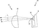
图11与图12都表示涉及本发明的前照灯的结构的一例,本图是说明利用来自发光元件的直射光的结构形式的示意图;Both Fig. 11 and Fig. 12 show an example of the structure of the headlamp related to the present invention, and this figure is a schematic diagram illustrating a structural form utilizing direct light from a light-emitting element;
图12是利用反射光的构成方式的示意图;Fig. 12 is a schematic diagram of a configuration using reflected light;
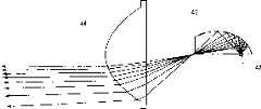
图13与图14都表示对于灯具的构成要素光学配置的一例,本图是纵剖面图;Both Figure 13 and Figure 14 show an example of the optical configuration of the constituent elements of the lamp, and this figure is a longitudinal sectional view;
图14是水平剖面图;Figure 14 is a horizontal sectional view;
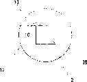
图15是表示前照灯的构成例的正面图;15 is a front view showing a configuration example of a headlight;
图16是示意表示配光图形的形成例的图。FIG. 16 is a diagram schematically showing a formation example of a light distribution pattern.
部件编号说明Part Number Description
1、23、26发光元件;1a发光部;2芯片部;3反射部;4萤光体;5透镜部;29、35车用前照灯;30、36透镜;31、38光学系统;37反射镜;42发光元件。1, 23, 26 light-emitting element; 1a light-emitting part; 2 chip part; 3 reflection part; 4 phosphor; 5 lens part; 29, 35 vehicle headlights; reflector; 42 light emitting elements.
具体实施方式Detailed ways
本发明涉及使用发光元件作为光源的车用前照灯,能够适用于前照灯或雾灯等。另外,对于应用半导体的发光元件可以例举诸如由P-N结中正向流动的电流发光的LED元件,或通过电场发光的EL元件等。The present invention relates to a vehicle headlamp using a light-emitting element as a light source, and can be applied to headlamps, fog lamps, and the like. In addition, examples of light-emitting elements using semiconductors include LED elements that emit light from current flowing forward through a P-N junction, or EL elements that emit light through an electric field.
图1是以LED为例示意表示发光元件构造的图。FIG. 1 is a diagram schematically showing the structure of a light emitting element by taking an LED as an example.
发光元件1具有芯片部2、反射部3、萤光体4、透镜5,在本例,发光部1a由芯片部2、反射部3、萤光体4构成。另外,光学系统的焦点位置设定在发光部或者该发光部的近处。在此所说的“焦点”不局限于反射镜或者透镜本身的狭义的焦点,包括光学上的形状设计的基准点等。The light emitting element 1 has a
对于芯片部2,例如使用Al-In-Ga-P型、In-Ga-N型等材料,如图所示,具有在支持部件(引线框或管座等)上直接安装芯片部2的方法和在辅助安装部件上安装芯片然后在支持部件上安装辅助安装部件的方法;另外,在芯片2上形成的电极上连接焊线(没作图示)。For the
在设在芯片部2的周围的部件上形成反射部3。例如,芯片部2的支持部件具有杯子形状的部分,通过在杯子形状的部分形成凹面,而形成反射面。在芯片部2发出的光具有以发光元件1的光轴为中心的指向特性,越远离光轴光的强度越弱。于是,在图中区分成以“6a”表示的直射光和以“6b”、“6c”表示的反射光的情况下,光轴方向的直射光最强,而为了有效地利用如“6b”那样的从芯片部2的侧方发射的光,设置了反射部3。即,在该反射部3的反射面,光被反射成为向前方(照射方向)的光。另外,“6c”表示从发光层发射后向着照射方向相反的方向的光,该光通过在芯片部2的后端面的反射,成为向前方的光,或者在芯片2的后端面反射后,再从芯片部2的侧面射出然后再被反射部3反射。Reflecting portion 3 is formed on members provided around
萤光体4覆盖芯片部2及其周围。例如,为了取得白色光,可以使用发兰色光的芯片和YAG萤光体等发黄光的材料进行调色。Phosphor 4 covers
透镜部5配置在芯片部2的前方,或者形成把发光部1a包入树酯透镜内的结构,后者采用通过把发光部整体埋入树酯内提高指向性的方法,例如,形成炮弹型用作制动灯是众所周知的。为了不形成从芯片部2以广角发射的光在透镜内部或者反射或者从透镜侧面部射出损失的光,使用圆屋顶形或者半球形的透镜是理想的。另外,通过利用全反射和反射装置进行光路控制有效地发出芯片部的放射光,从而提高光的利用效率是理想的。The lens part 5 is disposed in front of the
从发光元件的光轴方向看,用发光部的光源像形成圆形的元件,在发光部发生的光中的大半部分是直射光,这对形成圆形的图形有作用,位于其周围的圆环状的图形由从透镜部的侧面发出的光形成而成为拟似光源。Viewed from the direction of the optical axis of the light-emitting element, the light source image of the light-emitting part forms a circular element, and most of the light generated in the light-emitting part is direct light, which has an effect on forming a circular figure. The circle around it The ring-shaped figure is formed by the light emitted from the side surface of the lens part, and becomes a pseudo light source.
这样,当光源的光度分布在光轴周围具有转动对称性的情况下,因为必须要基于从光轴方向看大体形成圆形的图形,形成非转动对称性的配光图形,这会使光学设计困难。例如,形成近光的射束配光中的分界线那样的直线部分是困难的。(因为将形成圆弧状的部分简单地互相连接难以形成明确的直线部)。In this way, when the luminosity distribution of the light source has rotational symmetry around the optical axis, it is necessary to form a non-rotational symmetric light distribution pattern based on a substantially circular figure viewed from the direction of the optical axis, which will make the optical design difficulty. For example, it is difficult to form a straight portion such as a dividing line in the beam distribution of the low beam. (Because it is difficult to form a clear linear portion simply by connecting the arc-shaped portions to each other).
在此,当发光元件的光度分布在光轴周围具有非转动对称性的情况下,因为发光部具有沿着与发光元件的光轴直交的方向横向长的形状,所以,构成通过光学系统投影的图形形状具有直线的部分。Here, when the light intensity distribution of the light-emitting element has non-rotational symmetry around the optical axis, since the light-emitting portion has a laterally long shape in a direction perpendicular to the optical axis of the light-emitting element, it constitutes a projection projected by the optical system. Graphical shapes have straight sections.
图2表示从发光元件的光轴方向看的形状例,是示意表示与发光元件有关的光源像的图形形状的例。FIG. 2 shows an example of the shape seen from the direction of the optical axis of the light-emitting element, and is an example of a graphic shape schematically showing a light source image related to the light-emitting element.
如图所示,光源像7的图形形状的外周边缘大体形成矩形。As shown in the figure, the outer peripheral edge of the graphic shape of the light source image 7 is substantially rectangular.
在本例,从光轴方向看的发光部1a的形状为长方形,如后面所述地该光源像主要是在其长方向扩大。In this example, the shape of the light emitting part 1a viewed from the optical axis direction is a rectangle, and the light source image mainly expands in its longitudinal direction as will be described later.
另外,为了得到横向长的投影图形,比采用正方形的光源像,形成长方形是理想的。另外,因为长方向的端部不限于直线状,所以,也可以如虚线7′所示的光源像那样去除长方形的4个角,形成圆弧的形状。In addition, in order to obtain a horizontally long projection pattern, it is preferable to form a rectangle rather than a square light source image. In addition, since the end in the longitudinal direction is not limited to a linear shape, the four corners of a rectangle may be removed to form an arc shape like a light source shown by a dotted line 7'.
为了获得这样的光源像,对构成发光元件的芯片部、反射部、萤光体或者透镜部形状的设计要使在该发光元件的光轴周围具有非对称性。即,决定光源像的图形形状的要素是芯片部的形状、反射部或萤光体的形状、透镜部的形状及材质,还有与这些构成部件有关的光学的位置关系。因而,根据组合各要素的模拟结果(光线跟踪和光线分布),能够设计具有理想光源像的发光元件。In order to obtain such a light source image, the shape of the chip portion, reflection portion, phosphor, or lens portion constituting the light emitting element is designed to have asymmetry around the optical axis of the light emitting element. That is, the elements that determine the graphic shape of the light source image are the shape of the chip portion, the shape of the reflection portion or phosphor, the shape and material of the lens portion, and the optical positional relationship between these components. Therefore, it is possible to design a light-emitting element having an ideal light source image based on the simulation results (ray tracing and ray distribution) combining the respective elements.
可以举出把从光轴方向看的发光部做成所要求的形状,如长方形,用半圆柱状等的树脂透镜覆盖发光部的结构。但为此要把芯片部设计成任意形状,考虑伴随各种技术困难及对制造成本的不利影响等,如下所述,进行涉及反射部和萤光体的形状设计的方法是有效的。Examples include a configuration in which the light-emitting portion viewed from the optical axis direction is made into a desired shape, such as a rectangle, and the light-emitting portion is covered with a semi-cylindrical resin lens. However, it is effective to design the chip portion in an arbitrary shape for this purpose, which entails various technical difficulties and adverse effects on manufacturing costs. As described below, it is effective to design the shape of the reflective portion and the phosphor.
在把反射部3的形状设计成在光轴周围非旋转对称,适于灯具配光的形状的设计方法中,不对芯片部的形状和指向特性进行大幅变更就可以改变亮度分布。In the design method of designing the shape of the reflector 3 to be non-rotationally symmetrical around the optical axis and suitable for the light distribution of the lamp, the luminance distribution can be changed without greatly changing the shape and directional characteristics of the chip portion.
图3、图4是表示从发光元件光轴方向看的芯片部及反射部的例图。芯片部2全为正方形。3 and 4 are diagrams showing examples of a chip portion and a reflection portion viewed from the direction of the optical axis of the light emitting element. The
图3所示的反射部3A具有其外周缘做成圆弧状的部分8和“ㄑ”字状的折线部分9,大致做成扇形。而从光轴方向看时,芯片部2的一边(图的上边)10和上述折线的一部分11局部几乎一致。即反射部3A做成如圆形中切除图中虚线所示的范围的形状。The
根据本例,在近光光束的配光图形中,可以得到对形成水平分界线及相对其倾斜的分界线适合的光源像。According to this example, in the light distribution pattern of the passing beam, it is possible to obtain a light source image suitable for forming a horizontal dividing line and a dividing line inclined thereto.
图4所示的反射部3B具有其外周缘形成圆弧状的部分12和直线状的部分13。而从光轴方向看时,芯片部2的一边(图的上边)10与上述部分13的直线部几乎一致。即反射部3B做成如圆形中切除图中用虚线所示范围的形状。Reflecting
根据本例,在近光光束的配光图形中,可以得到适于形成水平分界线的光源像。According to this example, in the light distribution pattern of the low beam, a light source image suitable for forming a horizontal dividing line can be obtained.
如上所述,涉及做成杯状的反射部,通过使从光轴方向看的形状为非旋转对称,考虑前照灯配光进行反射部的形状设计,可以得到对形成明确的分界线有效的光源像。As mentioned above, regarding the cup-shaped reflector, by making the shape viewed from the direction of the optical axis non-rotationally symmetric, and designing the shape of the reflector in consideration of the light distribution of the headlamp, it is possible to obtain a device that is effective for forming a clear boundary. light source image.
而若使用将从光轴方向看的萤光体4的形状做成与上述反射部3A、3B相同的形状,或所需要的形状的方法,可以进一步提高设计上的自由度。On the other hand, if the shape of the phosphor 4 viewed from the optical axis direction is the same as that of the
另外,由于来自芯片部2的直射光和由反射部3等产生的反射光通过透镜部5向外部射出,可以将涉及该透镜部的结构材料的折射率的选定及折射界面的形状设计组合在一起。例如最好将在透镜部5中具有透镜作用的界面(入射侧界面和出射侧界面)的形状做成非旋转对称(一般作成非球面形状)。In addition, since the direct light from the
如上所述,通过涉及发光元件的结构要素的光学设计,可以得到与发光元件有关的所需要的光源像。As described above, a desired light source image related to a light-emitting element can be obtained by optical design related to the constituent elements of the light-emitting element.
图5表示发光部的光源像的一例14。图中所示的纵轴“UD”表示沿垂直方向延伸的轴;横轴“LR”表示沿水平方向延伸的轴。FIG. 5 shows an example 14 of the light source image of the light emitting unit. The vertical axis "UD" shown in the figure represents an axis extending in the vertical direction; the horizontal axis "LR" represents an axis extending in the horizontal direction.
如图所示的图形形状中,其长边方向的侧缘部15具有与近光光束特有的分界线相似的形状。也就是说,作为UD轴左方,位于LR轴下方的侧缘中,向左斜方向延伸的部分15a在配光图形中对应倾斜的分界线,而作为UD轴右方,沿LR轴的下方的侧缘,即向左右方向延伸的部分15b对应配光图形中水平的分界线。In the graphic shape shown in the figure, the
由于通过将涉及在光轴周围作成非旋转对称的光源像的投影图形进行若干组合可以得到多种形状,则可以例如将两个长方形的图形组合得到光源像14那样的图形;使用单一的发光元件可以得到适于形成分界线的光源像,在容易进行涉及近光光束配光的光学设计这一点是非常重要的。(即只要光源像的图形形状是从开始就考虑配光图形作成的,构成光学系统的反射镜和透镜的设计就很方便。)Since a variety of shapes can be obtained by combining projection figures related to making non-rotationally symmetrical light source images around the optical axis, for example, two rectangular figures can be combined to obtain a figure like 14 of the light source; using a single light-emitting element It is very important that a light source image suitable for forming a boundary can be obtained to facilitate optical design related to low beam light distribution. (That is, as long as the graphic shape of the light source image is made by considering the light distribution pattern from the beginning, the design of the reflector and lens that constitute the optical system is very convenient.)
这样,通过将具有适于车用配光设计的光源像的发光元件设计成配光机能不同,将各发光元件按用途不同使用,可以在灯具设计上提高自由度(即与只使用具有一定形状的光源像的发光元件进行灯具设计的情况相比,配光控制的组合范围扩大)。In this way, by designing light-emitting elements with light source images suitable for vehicle-use light distribution design to have different light distribution functions, and using each light-emitting element according to different purposes, the degree of freedom in lamp design can be improved (that is, it is different from using only light-emitting elements with a certain shape). The combination range of light distribution control is expanded compared with the case of designing lamps with light-emitting elements such as light-emitting elements of different light sources).
以配光图形由光学系统形成的聚光性投影图形和扩散性的投影图形组合形成的情况为例,对适于形成各投影图形的发光元件的光源像进行以下说明。Taking the case where the light distribution pattern is formed by a combination of a concentrating projection pattern and a diffusing projection pattern formed by an optical system as an example, the light source image of a light emitting element suitable for forming each projection pattern will be described below.
图6是表示用于形成小聚光性或水平扩散性的投影图形的光源像的图。“UD”、“LR”的意思如图5中的说明(其在图7中也一样)。Fig. 6 is a diagram showing a light source image for forming a projection pattern with small concentrating property or horizontal diffusing property. The meanings of "UD" and "LR" are as explained in FIG. 5 (they are also the same in FIG. 7).
本例所示的光源像16作成在LR轴方向变长的大致长方形,其一边16a(图的下边)与LR轴一致。The
图7表示用于形成具有中等程度的水平扩散性或大的水平扩散性的投影图形的光源像17。FIG. 7 shows a
本例中光源像17也作成在LR轴方向变长的大致长方形,其一边17a(图的下边)与LR轴一致,与上述的光源像16相比,LR轴方向及UD轴方向的宽度变大。In this example, the
如图5到图7所示,通过使用各自具有分成不同机能的光源像的发光元件,可以将适于涉及近光光束配光的分界线、热区(亮度中心部)、中扩散性区、大扩散性区的投影图形合成,得到所需要的配光。As shown in FIGS. 5 to 7, by using light-emitting elements each having a light source image divided into different functions, the boundary line, hot zone (brightness center part), medium diffusivity zone, Synthesize the projection graphics of the large diffusivity area to obtain the required light distribution.
图8示意表示通过按机能不同生成四种图形,将它们重迭组合得到的配光图形。横轴上的“H”表示水平线;纵轴上的“V”表示铅垂线。FIG. 8 schematically shows a light distribution pattern obtained by generating four patterns according to different functions and superimposing them. "H" on the horizontal axis indicates a horizontal line; "V" on the vertical axis indicates a plumb line.
本例配光图形18由以下图形构成。The
·主要对分界线形成有用的投影图形(19)·Mainly form useful projection graphics for dividing lines(19)
·三个水平扩散性的投影图形(20、21、22)·Three horizontally diffuse projected figures (20, 21, 22)
这些图形作为主要在水平方向放大的投影像的集合,形成涉及各发光元件的光源像。在投影图形20、21、22中,图形20扩散性最小,图形21的扩散性为中等,图形22扩散性最大。另外,使用的发光元件是两种以上(如四种)。These patterns form a light source image related to each light emitting element as a collection of projected images enlarged mainly in the horizontal direction. Among the projected
这样,在分别包括用于形成聚光性投影图形的发光元件、用于形成扩散性投影图形的发光元件、及用于形成分界线的发光元件的同时,形成各自的光源像具有在配光机能上不同的形状的结构最为理想。In this way, while respectively including light-emitting elements for forming concentrating projection patterns, light-emitting elements for forming diffuse projection patterns, and light-emitting elements for forming boundary lines, forming respective light source images has the function of light distribution function. Structures with different shapes are ideal.
对于使用多个发光元件的结构形式,不限于在一个发光元件内有一个芯片部的结构。如图9、图10所示(上方表示平面图;下方表示立体图),也可以有在发光元件内排列多个芯片部的结构。The structural form using a plurality of light emitting elements is not limited to the structure having one chip portion in one light emitting element. As shown in FIGS. 9 and 10 (the top shows a plan view; the bottom shows a perspective view), there may be a structure in which a plurality of chip portions are arranged in a light emitting element.
如图9所示,具有在发光元件23的内部沿规定方向配例矩形状的芯片部24、24、......的结构,用形成半圆柱状的萤光体或者透明部件25覆盖这些芯片或者在设置各芯片部的基板的前方配置透明部件。As shown in FIG. 9, it has a structure in which
通过在圆筒部件(基材)的侧面(圆筒面)配列多个芯片部,与形成与灯丝形状(理想形状为圆筒形状)相同的构成方式相比较,由于在本例使用半圆柱状的萤光体或者透明部件,可以获得诸如能减小光源尺寸以及对发光元件不需使用特殊的光学系统这样的优点。By arranging a plurality of chip parts on the side surface (cylindrical surface) of a cylindrical member (base material), compared with the configuration method of forming the same shape as the filament (the ideal shape is a cylindrical shape), in this example, a semi-cylindrical chip is used. Phosphors or transparent members, such advantages as being able to reduce the size of the light source and eliminating the need to use a special optical system for the light-emitting element, can be obtained.
在图10所示例中,具有在发光元件26的内部排列着四个矩形芯片部27、27、27、27的结构。即使各个芯片部的中心位于正方形或长方形的各顶点而形成两行两列的配置。之后,用萤光体或透明部件28覆盖这些芯片部,或在设置各芯片部的基板的前方配置透明部件。In the example shown in FIG. 10 , four rectangular chip portions 27 , 27 , 27 , 27 are arranged inside a light emitting element 26 . Even if the center of each chip portion is located at each apex of a square or a rectangle, an arrangement of two rows and two columns is formed. Thereafter, these chip portions are covered with phosphors or transparent members 28, or transparent members are arranged in front of the substrate on which each chip portion is provided.
在所有的结构中,都可以通过使芯片部中的多个或全部发光,在光轴的周围得到非旋转对称的亮度分布。如在根据车辆行驶环境等可以改变配光分布构成的配光控制型灯具中,可以有选择性地对配光分布的形成所需的芯片部开灯,或根据使用光束的选择(近光光束或行驶光束等)有选择性地对必需的芯片部开灯。In all configurations, by making some or all of the chip portions emit light, a rotationally symmetric luminance distribution around the optical axis can be obtained. For example, in a light distribution control type lamp that can change the light distribution distribution according to the vehicle driving environment, etc., the chip part required for the formation of the light distribution distribution can be selectively turned on, or according to the selection of the used beam (low beam beam) Or driving beams, etc.) selectively turn on the necessary chip parts.
由于在芯片部电连接中使用的结合电缆遮住了来自芯片部的光,有时在光源像上产生阴影(暗线),在元件内部设置多个芯片部时成为问题。因而,最好选择电极位置,使结合电缆尽量不遮住芯片部的前方(照射方向),或者采用芯片部的侧边或侧面部能与结合电缆连接的结构。Since the bonding cable used for the electrical connection of the chip part blocks the light from the chip part, shadows (dark lines) may appear on the light source image, which becomes a problem when multiple chip parts are installed inside the device. Therefore, it is best to select the electrode position so that the bonding cable does not cover the front of the chip part (irradiation direction) as much as possible, or adopt a structure in which the side or side of the chip part can be connected to the bonding cable.
图11及图12表示涉及本发明的车用前照灯或构成该前照灯的照射部(照射单元)的构成例,作为使用投影光学系统的结构,可以列举出以下方式。11 and 12 show configuration examples of the vehicle headlamp according to the present invention or the irradiation unit (irradiation unit) constituting the headlamp, and examples of the configuration using the projection optical system include the following.
(A)主要利用由发光元件发射的直接光的方式(参照图11),(A) A method mainly utilizing direct light emitted from a light-emitting element (refer to FIG. 11 ),
(B)主要利用由发光元件发射后,用反射镜产生的反射光的方式(参照图12)。(B) A method mainly utilizing reflected light generated by a reflector after being emitted from a light-emitting element (see FIG. 12 ).
在图11所示的车用前照灯29,使用具有投影透镜30的光学系统(投影光学系统)31。即,在本例,具有发光元件32、遮光部件33(遮光罩)、投影透镜30,具有在支持部件34上设置发光元件32及遮光部件33的结构。而且,投影透镜30的物侧焦点设在遮光部件33的上边附近。另外,当投影由在遮光部件33的上边缘遮挡发光元件32发射的光的一部分形成像时,使遮光部件33的上边缘部尽量接近发光元件32是理想的。In the
使发光元件的光轴和灯具的光轴互相平行,在由该发光元件发的光中,没被设置在该发光元件的前方的遮光部件33遮挡而向前方的光1、1、...透过投影透镜30后成为照射光。另外,通过遮光部件33的上边形成决定配光图形的明暗边界的分界线。另外,当从发光元件32发出的光的放射角度大时,没透过投影透镜30的无效的光会增多,因此有必要考虑投影透镜的直径和位置,规定扩散角度。Make the optical axis of the light-emitting element and the optical axis of the lamp parallel to each other, and among the light emitted by the light-emitting element, the light 1, 1,... After passing through the
在图12所示的车用前照灯35,使用具有投影透镜36和反射镜37的光学系统38。即,在本例,具有发光元件39、反射镜37、投影透镜36,发光元件39和投影透镜36的支持部件40从侧方看形成曲柄状,其一部分成为遮光部40a。而且,反射镜37的焦点设定在发光元件39的发光部或者其附近,投影透镜36的物侧焦点设定在遮光部40a的近处。In the vehicle headlamp 35 shown in FIG. 12 , an optical system 38 including a projection lens 36 and a reflector 37 is used. That is, in this example, the light emitting element 39, the reflector 37, and the projection lens 36 are provided. The support member 40 having the light emitting element 39 and the projection lens 36 is crank-shaped when viewed from the side, and part of it serves as the light shielding portion 40a. Furthermore, the focal point of the reflecting mirror 37 is set at or near the light-emitting portion of the light-emitting element 39 , and the object-side focal point of the projection lens 36 is set near the light-shielding portion 40 a.
发光元件39,具有其光轴与灯具的光轴垂直相交的位置关系,安装在支持部件40上,从发光元件39发射的光的大半在反射镜37的反射面被反射。然后,没被遮光部40a遮挡向着前方的光1、1、...透过投影透镜36之后成为照射光。另外,通过遮光部40a的上边缘形成决定配光图形的明暗边界的分界线。另外,通过在发光元件39和遮光部40a之间设置平面反射镜41,能提高光束利用率。由于使用透明材料一体地形成支持部件40和投影透镜36,能够制造在发光元件39的安装位置、遮光部40a的上边缘位置、投影透镜36的焦点位置等方面的具有高精度的光学系统构成部件。The light emitting element 39 is mounted on the support member 40 in such a positional relationship that its optical axis perpendicularly intersects with the optical axis of the lamp, and most of the light emitted from the light emitting element 39 is reflected on the reflective surface of the reflector 37 . Then, the light 1 , 1 , . In addition, the upper edge of the light-shielding portion 40a forms a boundary line that determines the light-dark boundary of the light distribution pattern. In addition, by providing the plane reflector 41 between the light emitting element 39 and the light shielding portion 40a, the light beam utilization efficiency can be improved. Since the supporting member 40 and the projection lens 36 are integrally formed using a transparent material, it is possible to manufacture optical system components with high precision in terms of the mounting position of the light emitting element 39, the position of the upper edge of the light shielding portion 40a, the focus position of the projection lens 36, and the like. .
图13及图14对形式(B)的灯具例表示发光元件42、反射面43、投影透镜44的位置关系,图14表示纵(垂直)剖面图,图15表示水平剖面图。另外,图中省略了遮光部。13 and 14 show the positional relationship of light emitting
另外,作为反射面的形状,使用旋转椭圆面或椭圆一抛物复合面,或者使用以这些基本面通过曲面操作提高了自由度的自由曲面等。In addition, as the shape of the reflecting surface, an ellipsoid of revolution or a compound ellipse-parabola surface is used, or a free-form surface whose degree of freedom is increased by curved-surface manipulation based on these fundamental surfaces, or the like is used.
发光元件42的发光部在与灯具光轴平等的方向上具有横长的形状,通过该发光部的光源像借助光学系统放大,可以得到对应反射面43上的反射位置的投影图形。之后,使投影图形合成,形成配光图形。The light-emitting part of the light-emitting
图15是表示车用前照灯的构成例45的正面图,具有组合多个照射单元的结构。Fig. 15 is a front view showing a configuration example 45 of a vehicle headlamp, which has a configuration in which a plurality of irradiation units are combined.
配置在最上段的照射单元46、46...是扩散型,作为其配光机能,由具有中度的水平扩散性的照射单元和具有大的水平扩散性的照射单元构成。The
另外,配置在中段及最下段的照射单元是集光型,其中,位于中段的照射单元47、47主要照射对形成分界线有用的投影图形。其余的照射单元48、48...用于照射车前方的远区域,主要形成对热区域的形成有作用的投影图形。In addition, the irradiating units disposed in the middle and lowermost tiers are light-collecting types, and the irradiating
这些照射单元都具有图12所示的结构,根据配光机能的不同发光元件的发光部形状各异,同时,根据使用目的分别设计反射镜的焦点距离、遮光位置、投影透镜的后焦点等。These irradiating units all have the structure shown in Figure 12. The shapes of the light-emitting parts of the light-emitting elements are different according to the light distribution function. At the same time, the focal length of the reflector, the light-shielding position, and the back focus of the projection lens are designed according to the purpose of use.
至于照射单元的个数,在考虑灯具的小型化和低成本化等的情况下,全部为十个至十几个是理想的,对形成分界线有用的照射单元为两个,配置在灯具中央或者中段,在其左右及上下配置的小扩散、中扩散、大扩散的照射单元分别为两~三个是理想的。As for the number of irradiating units, considering the miniaturization and cost reduction of the luminaire, it is ideal to have all ten to a dozen or so, and two irradiating units useful for forming a dividing line are arranged in the center of the luminaire. Or in the middle section, it is ideal that two to three irradiation units of small diffusion, medium diffusion, and large diffusion are arranged on the left, right, and upper and lower sides respectively.
图16示意表示配光图形的形成例,左侧分开表示不同机能的投影图形,右侧表示合成全部图形的样子。另外,H线表示水平线、V线表示垂直线。Fig. 16 schematically shows an example of forming a light distribution pattern, the left side shows separately projected patterns of different functions, and the right side shows how all the patterns are synthesized. In addition, the H line represents a horizontal line, and the V line represents a vertical line.
聚光性的投影图形49、50中,面积相对小的图形49表示由照射单元48形成的图形,图形50表示由照射单元47形成的图形。Among the concentrating
另外,水平扩散性的投影图形51、52表示由照射单元48、48...形成的图形,由中度扩散性的照射单元形成图形51,由大扩散性的照射单元形成图形52。In addition, the projected
通过组合这些投影图形能形成明显的分界线,同时能提高光束利用率。Combining these projection graphics can form a clear dividing line, and at the same time can improve the utilization rate of light beams.
发明的效果The effect of the invention
由上述说明可知,根据发明的第一方面,由于通过使用光学系统,使从发光元件的光轴方向看成横长形状的发光部的光源像主要在水平方向放大,能够得到所需要的投影图形,所以使配光设计变得容易。另外,为了得到在光轴周围没有旋转对称性的配光分布,没有使反射镜等光学部件的形状和结构复杂化。As can be seen from the above description, according to the first aspect of the invention, by using the optical system, the light source image of the light-emitting part having a horizontally long shape viewed from the optical axis direction of the light-emitting element is mainly enlarged in the horizontal direction, and the desired projection pattern can be obtained. , so that the light distribution design becomes easy. In addition, in order to obtain a light distribution without rotational symmetry around the optical axis, the shape and structure of optical components such as mirrors are not complicated.
根据本发明第二方面,通过使用大体矩形的图形,能容易地获得适合车用前照灯配光的投影图形。According to the second aspect of the present invention, by using a substantially rectangular pattern, it is possible to easily obtain a projected pattern suitable for light distribution of a vehicle headlamp.
根据发明的第三方面,通过构成发光元件的芯片部、反射部和萤光体的形状设计,可以得到具有所需要的亮度分布的光源像。According to the third aspect of the invention, a light source image having a desired luminance distribution can be obtained by designing the shapes of the chip portion, the reflection portion, and the phosphor constituting the light emitting element.
根据本发明第四方面,能明显地形成近光的光束配光中的分界线。According to the fourth aspect of the present invention, the dividing line in the light beam distribution of the low beam can be clearly formed.
根据发明的第五方面,通过分别使用配光机能不同的发光元件,可以提高配光设计的自由度。According to the fifth aspect of the invention, the degree of freedom in light distribution design can be increased by using light-emitting elements with different light distribution functions.
根据发明的第六方面,通过将多个芯片部排列在一个元件内,能够实现小型化,通过使各个芯片部分别发光,可以得到各种亮度分布。According to the sixth aspect of the invention, miniaturization can be achieved by arranging a plurality of chip portions in one element, and various luminance distributions can be obtained by individually emitting light from each chip portion.
Claims (6)
Translated fromChineseApplications Claiming Priority (3)
| Application Number | Priority Date | Filing Date | Title |
|---|---|---|---|
| JP322651/02 | 2002-11-06 | ||
| JP2002322651AJP4294295B2 (en) | 2002-11-06 | 2002-11-06 | Vehicle headlamp |
| JP322651/2002 | 2002-11-06 |
Publications (2)
| Publication Number | Publication Date |
|---|---|
| CN1499126A CN1499126A (en) | 2004-05-26 |
| CN1255646Ctrue CN1255646C (en) | 2006-05-10 |
Family
ID=32105455
Family Applications (1)
| Application Number | Title | Priority Date | Filing Date |
|---|---|---|---|
| CNB200310113810XAExpired - Fee RelatedCN1255646C (en) | 2002-11-06 | 2003-11-04 | Vehicular headlamp |
Country Status (6)
| Country | Link |
|---|---|
| US (1) | US7357546B2 (en) |
| EP (1) | EP1418381B1 (en) |
| JP (1) | JP4294295B2 (en) |
| KR (1) | KR100532818B1 (en) |
| CN (1) | CN1255646C (en) |
| DE (1) | DE60325927D1 (en) |
Families Citing this family (54)
| Publication number | Priority date | Publication date | Assignee | Title |
|---|---|---|---|---|
| DE10308704A1 (en)* | 2003-02-28 | 2004-11-11 | Audi Ag | Headlamp with white light LED for road vehicle has reflector and aspherical collimating lens and has opaque barrier in lower part of beam between collimating and scattering lenses |
| JP2004311101A (en)* | 2003-04-03 | 2004-11-04 | Koito Mfg Co Ltd | Vehicle headlights and semiconductor light emitting devices |
| JP2004349130A (en)* | 2003-05-22 | 2004-12-09 | Koito Mfg Co Ltd | Vehicular lighting fixture |
| JP4138586B2 (en)* | 2003-06-13 | 2008-08-27 | スタンレー電気株式会社 | LED lamp for light source and vehicle headlamp using the same |
| JP4024721B2 (en)* | 2003-06-20 | 2007-12-19 | 株式会社小糸製作所 | Vehicle lamp and light source module |
| JP4314911B2 (en)* | 2003-08-20 | 2009-08-19 | スタンレー電気株式会社 | Vehicle headlamp |
| JP4140042B2 (en)* | 2003-09-17 | 2008-08-27 | スタンレー電気株式会社 | LED light source device using phosphor and vehicle headlamp using LED light source device |
| JP4402425B2 (en)* | 2003-10-24 | 2010-01-20 | スタンレー電気株式会社 | Vehicle headlamp |
| EP1596125B1 (en)* | 2004-05-14 | 2008-01-09 | C.R.F. Società Consortile per Azioni | A module for projecting a light beam, an optical device for the module, and a vehicle front light assembly |
| JP4537822B2 (en)* | 2004-10-14 | 2010-09-08 | スタンレー電気株式会社 | Lamp |
| US20060097385A1 (en)* | 2004-10-25 | 2006-05-11 | Negley Gerald H | Solid metal block semiconductor light emitting device mounting substrates and packages including cavities and heat sinks, and methods of packaging same |
| JP4428223B2 (en)* | 2004-12-07 | 2010-03-10 | 市光工業株式会社 | Vehicle lamp and vehicle headlamp device |
| JP2006210295A (en)* | 2005-01-31 | 2006-08-10 | Ichikoh Ind Ltd | Vehicle lamp and vehicle headlamp device |
| JP2006210296A (en)* | 2005-01-31 | 2006-08-10 | Ichikoh Ind Ltd | Vehicle lamp and vehicle headlamp device |
| US7316488B2 (en)* | 2005-02-07 | 2008-01-08 | Philips Lumileds Lighting Company, Llc | Beam shutter in LED package |
| TWI419375B (en)* | 2005-02-18 | 2013-12-11 | Nichia Corp | Light-emitting device with lens for controlling light distribution characteristics |
| DE102005041234A1 (en)* | 2005-08-31 | 2007-03-01 | Hella Kgaa Hueck & Co. | Headlight for vehicle, has optical units with characteristics in front of groups of sources in such a manner that different large light spots can be generated in traffic space by alternative switching on and off and/or dimming of sources |
| JP5033134B2 (en)* | 2005-11-17 | 2012-09-26 | コーニンクレッカ フィリップス エレクトロニクス エヌ ヴィ | LIGHTING DEVICE AND METHOD FOR DETERMINING LIGHT DIRECTION |
| DE102006005299A1 (en)* | 2006-02-06 | 2007-08-09 | Osram Opto Semiconductors Gmbh | Housing for a light-emitting diode component and light-emitting diode component |
| JP2007220572A (en)* | 2006-02-20 | 2007-08-30 | Stanley Electric Co Ltd | Lighting device |
| ES2373122T3 (en) | 2006-02-20 | 2012-01-31 | Stanley Electric Co., Ltd. | LIGHTING DEVICE. |
| DE602006001933D1 (en) | 2006-03-02 | 2008-09-04 | Fiat Ricerche | Module for light beam projection |
| JP4587048B2 (en)* | 2006-04-17 | 2010-11-24 | スタンレー電気株式会社 | Vehicle lighting |
| US7513665B2 (en) | 2006-05-16 | 2009-04-07 | Visteon Global Technologies, Inc. | Headlamp module and headlamp assembly with internally reflecting translucent member |
| WO2007139781A2 (en)* | 2006-05-23 | 2007-12-06 | Cree Led Lighting Solutions, Inc. | Lighting device |
| JP4683650B2 (en)* | 2006-05-29 | 2011-05-18 | 株式会社小糸製作所 | Vehicle lamp |
| DE102006046438B4 (en)* | 2006-09-25 | 2014-05-08 | Automotive Lighting Reutlingen Gmbh | Automotive headlamp with optimized light distribution |
| JP2008108674A (en)* | 2006-10-27 | 2008-05-08 | Stanley Electric Co Ltd | LED lighting fixtures |
| FR2913750A1 (en)* | 2007-03-14 | 2008-09-19 | Valeo Vision Sa | OPTICAL MODULE FOR MOTOR VEHICLE PROJECTOR |
| DE102007014215A1 (en)* | 2007-03-24 | 2008-09-25 | Hella Kgaa Hueck & Co. | Headlamp for vehicles comprises a primary lens element formed as a light guiding screen with mirror surfaces arranged on an inner side |
| KR100898818B1 (en)* | 2007-03-30 | 2009-05-22 | 한국광기술원 | Light-emitting diode bulb capable of light distribution control |
| JP5248833B2 (en)* | 2007-10-12 | 2013-07-31 | 株式会社小糸製作所 | Lighting fixtures for vehicles |
| US7690826B2 (en)* | 2007-11-29 | 2010-04-06 | Sl Seobong | Adaptive front light system using LED headlamp |
| JP5152502B2 (en)* | 2008-06-09 | 2013-02-27 | スタンレー電気株式会社 | Lamp |
| JP4618571B2 (en)* | 2008-12-19 | 2011-01-26 | スタンレー電気株式会社 | Light source device for vehicle headlamp |
| US20100246203A1 (en)* | 2009-03-27 | 2010-09-30 | North American Lighting, Inc. | System and method for exterior lighting of vehicles |
| DE202010018278U1 (en)* | 2010-01-15 | 2015-05-06 | Schott Ag | Collimated light source |
| JP5027898B2 (en)* | 2010-04-02 | 2012-09-19 | スタンレー電気株式会社 | Lighting fixture |
| KR101815606B1 (en)* | 2010-04-28 | 2018-01-05 | 스탠리 일렉트릭 컴퍼니, 리미티드 | Vehicle light |
| DE102010027212A1 (en)* | 2010-07-15 | 2012-01-19 | Osram Opto Semiconductors Gmbh | Radiation-emitting component |
| DE102010041114A1 (en)* | 2010-09-21 | 2012-03-22 | Osram Ag | lighting device |
| CN102121678B (en)* | 2011-01-15 | 2012-12-12 | 珠海晟源同泰电子有限公司 | Designing method of distribution module of LED lamp |
| TW201300258A (en)* | 2011-06-30 | 2013-01-01 | Phoenix Optronics Corp | Method of using lens imaging to control headlight hotspot |
| DE102012206397B4 (en) | 2012-04-18 | 2021-04-15 | Osram Gmbh | Lighting device with a screen, one side of which is irradiated by a first light source via a reflector and the other side, which is coated with a luminescent material, is irradiated by a second light source |
| FR2992738B1 (en)* | 2012-06-29 | 2014-08-08 | Peugeot Citroen Automobiles Sa | METHOD FOR DEFINING AN ASPHERIC LENS AND LIGHTING MODULE COMPRISING SUCH A LENS FOR A MOTOR VEHICLE PROJECTOR |
| KR101344427B1 (en) | 2012-09-06 | 2013-12-23 | 주식회사 에스엘 서봉 | Automotive lamp |
| US9327636B2 (en) | 2013-08-16 | 2016-05-03 | Coplus Inc. | Vehicle light apparatus |
| US9798070B2 (en) | 2013-11-05 | 2017-10-24 | Philips Lighting Holding B.V. | Light emitting device |
| JP6636244B2 (en) | 2014-12-04 | 2020-01-29 | 株式会社小糸製作所 | Road surface lighting unit |
| KR102460851B1 (en)* | 2015-09-04 | 2022-10-31 | 현대모비스 주식회사 | Vehicle lamp for implementing high beam |
| JP6782559B2 (en)* | 2016-05-13 | 2020-11-11 | 株式会社小糸製作所 | Vehicle headlights |
| US10605427B1 (en)* | 2018-10-24 | 2020-03-31 | Xuan Fan Electro-Optical Technology Co., Ltd. | Light source module and illumination device comprising the same |
| TWI803532B (en)* | 2018-11-02 | 2023-06-01 | 揚明光學股份有限公司 | Pattern projection device and manufacturing method thereof |
| CN111221112A (en)* | 2018-11-27 | 2020-06-02 | 扬明光学股份有限公司 | Pattern projection device and manufacturing method thereof |
Family Cites Families (21)
| Publication number | Priority date | Publication date | Assignee | Title |
|---|---|---|---|---|
| US1576035A (en)* | 1925-06-29 | 1926-03-09 | Ellsworth E Cipperly | Headlight |
| US2287308A (en)* | 1939-09-06 | 1942-06-23 | Hill William | Interlocking buckle |
| EP0106616B1 (en)* | 1982-10-15 | 1989-05-03 | Carello Lighting Plc | Road vehicle headlamp |
| JPS6318703U (en)* | 1986-07-21 | 1988-02-06 | ||
| US4935665A (en)* | 1987-12-24 | 1990-06-19 | Mitsubishi Cable Industries Ltd. | Light emitting diode lamp |
| DE3929955A1 (en)* | 1989-09-08 | 1991-03-14 | Inotec Gmbh Ges Fuer Innovativ | LIGHT SPOTLIGHTS |
| JP2559908B2 (en)* | 1991-02-08 | 1996-12-04 | 株式会社小糸製作所 | Projection type automobile headlamp |
| DE4228895C2 (en)* | 1992-08-29 | 2002-09-19 | Bosch Gmbh Robert | Motor vehicle lighting device with multiple semiconductor light sources |
| JP3207036B2 (en) | 1994-02-15 | 2001-09-10 | 株式会社小糸製作所 | Optical design method of lamp using light emitting element |
| DE19634754B4 (en)* | 1996-08-28 | 2012-05-03 | Automotive Lighting Reutlingen Gmbh | Headlamp system for vehicles for emitting variable light bundles |
| US5813753A (en)* | 1997-05-27 | 1998-09-29 | Philips Electronics North America Corporation | UV/blue led-phosphor device with efficient conversion of UV/blues light to visible light |
| US6340824B1 (en)* | 1997-09-01 | 2002-01-22 | Kabushiki Kaisha Toshiba | Semiconductor light emitting device including a fluorescent material |
| TW493054B (en)* | 1999-06-25 | 2002-07-01 | Koninkl Philips Electronics Nv | Vehicle headlamp and a vehicle |
| JP3926957B2 (en)* | 1999-12-09 | 2007-06-06 | 株式会社小糸製作所 | Headlamp for vehicle and method for forming reflector thereof |
| DE10005795C2 (en) | 2000-02-10 | 2003-06-12 | Inst Mikrotechnik Mainz Gmbh | Headlamp with a number of individual light emitters |
| JP3553471B2 (en)* | 2000-02-25 | 2004-08-11 | スタンレー電気株式会社 | Vehicle headlights |
| DE10009782B4 (en)* | 2000-03-01 | 2010-08-12 | Automotive Lighting Reutlingen Gmbh | Lighting device of a vehicle |
| DE10039433B4 (en)* | 2000-08-11 | 2017-10-26 | Osram Opto Semiconductors Gmbh | Semiconductor chip for optoelectronics |
| JP3839237B2 (en)* | 2000-09-18 | 2006-11-01 | 株式会社小糸製作所 | Vehicle lighting |
| JP2002367416A (en)* | 2001-06-12 | 2002-12-20 | Ichikoh Ind Ltd | head lamp |
| US6637922B2 (en)* | 2001-10-26 | 2003-10-28 | Demax Enterprise Co., Ltd. | Brightness enhanced head lamp apparatus |
- 2002
- 2002-11-06JPJP2002322651Apatent/JP4294295B2/ennot_activeExpired - Lifetime
- 2003
- 2003-11-04EPEP03025387Apatent/EP1418381B1/ennot_activeExpired - Lifetime
- 2003-11-04USUS10/699,815patent/US7357546B2/ennot_activeExpired - Fee Related
- 2003-11-04CNCNB200310113810XApatent/CN1255646C/ennot_activeExpired - Fee Related
- 2003-11-04DEDE60325927Tpatent/DE60325927D1/ennot_activeExpired - Lifetime
- 2003-11-06KRKR10-2003-0078230Apatent/KR100532818B1/ennot_activeExpired - Fee Related
Also Published As
| Publication number | Publication date |
|---|---|
| JP2004158292A (en) | 2004-06-03 |
| US7357546B2 (en) | 2008-04-15 |
| US20040136202A1 (en) | 2004-07-15 |
| CN1499126A (en) | 2004-05-26 |
| JP4294295B2 (en) | 2009-07-08 |
| DE60325927D1 (en) | 2009-03-12 |
| EP1418381B1 (en) | 2009-01-21 |
| KR100532818B1 (en) | 2005-12-05 |
| KR20040040390A (en) | 2004-05-12 |
| EP1418381A3 (en) | 2007-01-17 |
| EP1418381A2 (en) | 2004-05-12 |
Similar Documents
| Publication | Publication Date | Title |
|---|---|---|
| CN1255646C (en) | Vehicular headlamp | |
| CN1285855C (en) | Vehicular headlamp and mfg. method thereof | |
| CN1267676C (en) | Vehicular headlamp employing semiconductor light source | |
| CN1280575C (en) | Headlight for vehicle | |
| CN1221759C (en) | Front Lamp for vehicle | |
| CN100559058C (en) | vehicle headlights | |
| JP4665205B2 (en) | Linear light source for lamp | |
| CN100578074C (en) | car headlights | |
| CN1900580A (en) | Vehicle lamp | |
| CN1526985A (en) | car headlights | |
| CN1583465A (en) | Light source device for vehicle headlamp and vehicle headlamp | |
| CN1661275A (en) | Vehicle headlamp | |
| CN1766408A (en) | lamps | |
| CN101055066A (en) | Vehicle lamp | |
| CN1536263A (en) | Automotive headlamps and semiconductor light emitting elements | |
| CN1676987A (en) | Vehicle illumination lamp | |
| JP2009266434A (en) | Light source module and lighting fixture for vehicle | |
| CN1576689A (en) | Lamps apparatus and front viewing lamp for vehicle | |
| CN104160207A (en) | Light source for headlight and headlight | |
| JP5041307B2 (en) | Vehicle headlamp | |
| JP2008108942A (en) | Light source device | |
| JP4644243B2 (en) | Vehicle headlamp | |
| JP5266607B2 (en) | Vehicle headlamp | |
| JP4940488B2 (en) | Vehicle headlamp |
Legal Events
| Date | Code | Title | Description |
|---|---|---|---|
| C06 | Publication | ||
| PB01 | Publication | ||
| C10 | Entry into substantive examination | ||
| SE01 | Entry into force of request for substantive examination | ||
| C14 | Grant of patent or utility model | ||
| GR01 | Patent grant | ||
| CF01 | Termination of patent right due to non-payment of annual fee | ||
| CF01 | Termination of patent right due to non-payment of annual fee | Granted publication date:20060510 Termination date:20211104 |