CN1255082C - Chiropractic Correction and Immobilization Devices - Google Patents
Chiropractic Correction and Immobilization DevicesDownload PDFInfo
- Publication number
- CN1255082C CN1255082CCN01823649.9ACN01823649ACN1255082CCN 1255082 CCN1255082 CCN 1255082CCN 01823649 ACN01823649 ACN 01823649ACN 1255082 CCN1255082 CCN 1255082C
- Authority
- CN
- China
- Prior art keywords
- screw
- screwdriver
- head
- designed
- vertebral alignment
- Prior art date
- Legal status (The legal status is an assumption and is not a legal conclusion. Google has not performed a legal analysis and makes no representation as to the accuracy of the status listed.)
- Expired - Fee Related
Links
Images


Classifications
- A—HUMAN NECESSITIES
- A61—MEDICAL OR VETERINARY SCIENCE; HYGIENE
- A61B—DIAGNOSIS; SURGERY; IDENTIFICATION
- A61B17/00—Surgical instruments, devices or methods
- A61B17/56—Surgical instruments or methods for treatment of bones or joints; Devices specially adapted therefor
- A61B17/58—Surgical instruments or methods for treatment of bones or joints; Devices specially adapted therefor for osteosynthesis, e.g. bone plates, screws or setting implements
- A61B17/68—Internal fixation devices, including fasteners and spinal fixators, even if a part thereof projects from the skin
- A61B17/70—Spinal positioners or stabilisers, e.g. stabilisers comprising fluid filler in an implant
- A61B17/7001—Screws or hooks combined with longitudinal elements which do not contact vertebrae
- A61B17/7035—Screws or hooks, wherein a rod-clamping part and a bone-anchoring part can pivot relative to each other
- A61B17/7037—Screws or hooks, wherein a rod-clamping part and a bone-anchoring part can pivot relative to each other wherein pivoting is blocked when the rod is clamped
- A—HUMAN NECESSITIES
- A61—MEDICAL OR VETERINARY SCIENCE; HYGIENE
- A61B—DIAGNOSIS; SURGERY; IDENTIFICATION
- A61B17/00—Surgical instruments, devices or methods
- A61B17/56—Surgical instruments or methods for treatment of bones or joints; Devices specially adapted therefor
- A61B17/58—Surgical instruments or methods for treatment of bones or joints; Devices specially adapted therefor for osteosynthesis, e.g. bone plates, screws or setting implements
- A61B17/68—Internal fixation devices, including fasteners and spinal fixators, even if a part thereof projects from the skin
- A61B17/70—Spinal positioners or stabilisers, e.g. stabilisers comprising fluid filler in an implant
- A61B17/7001—Screws or hooks combined with longitudinal elements which do not contact vertebrae
- A61B17/7032—Screws or hooks with U-shaped head or back through which longitudinal rods pass
- A—HUMAN NECESSITIES
- A61—MEDICAL OR VETERINARY SCIENCE; HYGIENE
- A61B—DIAGNOSIS; SURGERY; IDENTIFICATION
- A61B17/00—Surgical instruments, devices or methods
- A61B17/56—Surgical instruments or methods for treatment of bones or joints; Devices specially adapted therefor
- A61B17/58—Surgical instruments or methods for treatment of bones or joints; Devices specially adapted therefor for osteosynthesis, e.g. bone plates, screws or setting implements
- A61B17/68—Internal fixation devices, including fasteners and spinal fixators, even if a part thereof projects from the skin
- A61B17/70—Spinal positioners or stabilisers, e.g. stabilisers comprising fluid filler in an implant
- A61B17/7001—Screws or hooks combined with longitudinal elements which do not contact vertebrae
- A61B17/7035—Screws or hooks, wherein a rod-clamping part and a bone-anchoring part can pivot relative to each other
- A61B17/7038—Screws or hooks, wherein a rod-clamping part and a bone-anchoring part can pivot relative to each other to a different extent in different directions, e.g. within one plane only
- A—HUMAN NECESSITIES
- A61—MEDICAL OR VETERINARY SCIENCE; HYGIENE
- A61B—DIAGNOSIS; SURGERY; IDENTIFICATION
- A61B17/00—Surgical instruments, devices or methods
- A61B17/56—Surgical instruments or methods for treatment of bones or joints; Devices specially adapted therefor
- A61B17/58—Surgical instruments or methods for treatment of bones or joints; Devices specially adapted therefor for osteosynthesis, e.g. bone plates, screws or setting implements
- A61B17/68—Internal fixation devices, including fasteners and spinal fixators, even if a part thereof projects from the skin
- A61B17/70—Spinal positioners or stabilisers, e.g. stabilisers comprising fluid filler in an implant
- A61B17/7049—Connectors, not bearing on the vertebrae, for linking longitudinal elements together
Landscapes
- Health & Medical Sciences (AREA)
- Orthopedic Medicine & Surgery (AREA)
- Life Sciences & Earth Sciences (AREA)
- Neurology (AREA)
- Surgery (AREA)
- Molecular Biology (AREA)
- General Health & Medical Sciences (AREA)
- Biomedical Technology (AREA)
- Heart & Thoracic Surgery (AREA)
- Medical Informatics (AREA)
- Nuclear Medicine, Radiotherapy & Molecular Imaging (AREA)
- Animal Behavior & Ethology (AREA)
- Engineering & Computer Science (AREA)
- Public Health (AREA)
- Veterinary Medicine (AREA)
- Surgical Instruments (AREA)
- Prostheses (AREA)
- Load-Engaging Elements For Cranes (AREA)
- Forklifts And Lifting Vehicles (AREA)
- Ultra Sonic Daignosis Equipment (AREA)
Abstract
Translated fromChineseDescription
Translated fromChinese技术领域technical field
本发明总体上涉及一种用于对椎体进行校正和固定的方法及装置。The present invention generally relates to a method and apparatus for alignment and fixation of a vertebral body.
背景技术Background technique
椎弓根螺钉(Pedicle screws)允许椎骨外科医生将杆或者板固附在胸椎骨和腰椎骨上。这样能够刚性固定住椎骨片断,促进移植骨生长融合,将椎骨片断固接成一个实体,减轻痛苦并且减小变形,却无需在康复过程中长时间使得病人完全不动。Pedicle screws allow vertebral surgeons to attach rods or plates to the thoracic and lumbar vertebrae. This can rigidly fix the vertebral fragments, promote the growth and fusion of the grafted bone, fix the vertebral fragments into a solid body, relieve pain and reduce deformation, but it is not necessary to keep the patient completely immobile for a long time during the rehabilitation process.
尽管已经研发出了许多不同的椎弓根螺钉,但是目前大多数椎弓根螺钉均是固定轴装置,它们必须在插入和固定于椎骨中的过程中被小心地进行校正。具体来说,所述螺钉必须被以一个非常特殊的角度钻入或者螺接入骨头内,以确保校正硬件得以精确定位,以便使得固定部件上的接收部分得以校正,从而所述杆可以贯穿其中,却不会扭曲所述螺钉或者在固附部位上施加过度的应力。由此,校正过程需要相当长的时间,增大了外科手术过程中复杂的可能性,在许多情况下,校正操作会失败并且必须反复进行。还有,螺钉的插入操作取决于所需的校正角度,导致插入操作在相对于椎体来说并非非常可靠或者安全的位置进行。Although many different pedicle screws have been developed, most current pedicle screws are fixed-shaft devices that must be carefully aligned during insertion and fixation in the vertebrae. Specifically, the screw must be drilled or threaded into the bone at a very specific angle to ensure that the alignment hardware is positioned precisely so that the receiving portion on the fixation member is aligned so that the rod can pass through it , without distorting the screw or placing undue stress on the attachment site. Thus, the correction process takes a considerable amount of time, increases the possibility of complications in the surgical procedure, and in many cases the correction operation fails and has to be repeated. Also, the insertion operation of the screw depends on the desired correction angle, resulting in an insertion operation at a position that is not very reliable or safe relative to the vertebral body.
本技术领域包含有多种椎弓根螺钉,它们允许以一定的自由度对螺钉和联结元件进行校正。但是,这些技术通常较为复杂,并且相对于使用寿命来说可靠性不足。与现有系统相伴的显著缺点包括有限的角度调节性、复杂度、对联结元件和所述杆进行合适定位的难度、许多与所述复杂装置相关联的许多部件的乏闷操作、以及制造这些复杂机构的成本相当高。The state of the art encompasses a variety of pedicle screws that allow for a certain degree of freedom in the alignment of the screw and coupling elements. However, these technologies are often complex and not reliable enough relative to their lifetime. Significant disadvantages associated with existing systems include limited angular adjustability, complexity, difficulty in properly positioning the coupling element and the rod, tedious handling of the many parts associated with the complex device, and manufacturing these The cost of a complex mechanism is quite high.
因此,就存在一种需求,即提供一种不太昂贵、经久耐用并且简单的脊椎校正装置,其允许外科医生自由地操控对联结硬件进行校正,从而使得所述固定杆可以相对于椎体得以正确定位,却无需进行耗时并且存在潜在危险的校正操作。Therefore, there is a need to provide an inexpensive, durable and simple spinal correction device that allows the surgeon free rein to correct the articulation hardware so that the rod can be adjusted relative to the vertebral body. Correct positioning without time-consuming and potentially dangerous corrections.
发明概述Summary of the invention
本发明总体上涉及一种用于校正和固定椎体的方法及装置。更具体地说,本发明涉及一种脊椎校正/固定装置及方法,其允许外科医生操控和校正所述单元,将固定部件与椎弓根螺钉联结起来,所述装置包括一个带有半球形头部的椎弓根螺钉,其位于一个带有切槽的联结元件的内部,所述联结元件被设计成允许对椎弓根螺钉进行高达至少90度的角度调节,并且一旦一根标准的校正杆已经被插入到带有切槽的联结元件之内,那么可以经由单个带有螺纹的锁定螺母被牢固地锁定到位。所述脊椎校正/固定装置能够在对椎弓根螺钉进行最终定位和将椎弓根螺钉插入到椎体内部之后对固定系统部件进行角度调节。The present invention generally relates to a method and apparatus for aligning and immobilizing a vertebral body. More specifically, the present invention relates to a spinal alignment/fixation device and method that allows the surgeon to manipulate and align the unit, coupling the fixation components to the pedicle screws, said device comprising a hemispherical head pedicle screw located inside a slotted coupling element designed to allow angular adjustment of the pedicle screw up to at least 90 degrees and once a standard correction rod has been inserted into the slotted coupling element, it can then be securely locked in place via a single threaded locking nut. The spinal alignment/fixation device enables angular adjustment of fixation system components after final positioning of the pedicle screw and insertion of the pedicle screw into the interior of the vertebral body.
在一个实施例中,本发明中的脊椎校正/固定装置总体上由三个主要组件构成:一个半球形椎弓根螺钉;一个带有切槽的联结元件,其被设计成接收所述椎弓根螺钉和一根校正杆;以及一个固定螺母,用于对联结元件的角度位置进行固定并且对所述校正杆在联结元件内部的位置进行固定。In one embodiment, the spinal alignment/fixation device of the present invention is generally composed of three main components: a hemispherical pedicle screw; a coupling element with slots designed to receive said pedicle A screw and an adjustment rod; and a fixing nut for fixing the angular position of the coupling element and for fixing the position of the adjustment rod inside the coupling element.
在一个示例性替代实施例中,本发明中的椎弓根螺钉具有一个带有切槽的尖端,以允许所述螺钉自攻到椎体上,并且由此易于将所述螺钉插入到骨头之内。In an exemplary alternative embodiment, the pedicle screw of the present invention has a notched tip to allow the screw to self-tap into the vertebral body and thereby facilitate insertion of the screw into the bone. Inside.
在另外一个示例性实施例中,所述固定螺母上与校正杆发生配合的部分被构造成提供一个对校正杆的较为牢固抓握力。In another exemplary embodiment, the portion of the fixing nut that cooperates with the correction rod is configured to provide a firmer grip on the correction rod.
在再一个示例性实施例中,所述固定螺母具有一个圆环状通道,该圆环状通道被设置成可以通过其插入一个螺钉驱动器,并且与椎弓根螺钉相互作用来将所述螺钉螺接入椎体之内。In yet another exemplary embodiment, the fixation nut has an annular channel configured to insert a screw driver therethrough and interact with the pedicle screw to screw the screw into the pedicle. into the vertebral body.
在又一个示例性实施例中,所述椎弓根螺钉在其半球形头部上带有一个正方形开口,以便使得一个带有正方形头部的驱动工具可以与其相匹配,来将所述螺钉螺接入椎体之内。In yet another exemplary embodiment, the pedicle screw has a square opening on its hemispherical head so that a driving tool with a square head can into the vertebral body.
在另外一个示例性实施例中,所述系统的组件由一种适用于整形外科手术的材料制成,比如不锈钢或者钛。In another exemplary embodiment, the components of the system are made of a material suitable for orthopedic surgery, such as stainless steel or titanium.
在又一个优选实施例中,本发明涉及一种用于校正和固定椎体的系统,包括多个如前所述固附在合适固附位置处的脊椎校正组件,所述固附位置根据椎骨的变形度得以确定。In yet another preferred embodiment, the present invention relates to a system for aligning and immobilizing a vertebral body, comprising a plurality of spinal alignment assemblies as previously described attached at suitable attachment locations according to the vertebrae The degree of deformation is determined.
在又一个实施例中,本发明涉及一种用于校正椎体的方法。该方法包括使用一个如前所述的脊椎校正系统对椎骨进行操控、校正和固定。In yet another embodiment, the invention relates to a method for correcting a vertebral body. The method includes manipulating, aligning and immobilizing the vertebrae using a spinal alignment system as previously described.
附图说明Description of drawings
当结合附图进行考虑时,本发明的这些和其它特征以及优点将通过参照下面的详细描述更好地得以理解,其中:These and other features and advantages of the present invention will be better understood by reference to the following detailed description when considered in conjunction with the accompanying drawings, in which:
图1是一个根据本发明未组装起来的椎弓根螺钉实施例的侧视图。Figure 1 is a side view of an unassembled embodiment of a pedicle screw according to the present invention.
图2a是一个根据本发明局部组装起来的椎弓根螺钉实施例的侧视图。Figure 2a is a side view of an embodiment of a partially assembled pedicle screw according to the present invention.
图2b是一个根据本发明局部组装起来的椎弓根螺钉实施例的前视图。Figure 2b is a front view of a partially assembled pedicle screw embodiment according to the present invention.
图2c是一个根据本发明局部组装起来的椎弓根螺钉实施例的前向局部剖视图。Figure 2c is an anterior partial cross-sectional view of an embodiment of a partially assembled pedicle screw according to the present invention.
图3a是一个根据本发明的固定螺母实施例的俯视图。Figure 3a is a top view of an embodiment of a retaining nut according to the present invention.
图3b是一个根据本发明的固定螺母实施例的剖视图。Figure 3b is a cross-sectional view of an embodiment of a retaining nut according to the present invention.
图3c是一个根据本发明的固定螺母实施例的侧视图。Figure 3c is a side view of an embodiment of a retaining nut according to the present invention.
图4a是一个根据本发明的椎弓根螺钉和螺钉驱动器实施例中的相互关系的侧视图。Figure 4a is a side view of the interrelationship of a pedicle screw and screw driver embodiment according to the present invention.
图4b是一个根据本发明的椎弓根螺钉和螺钉驱动器实施例中的相互关系的剖视图。Figure 4b is a cross-sectional view of the interrelationship of a pedicle screw and screw driver embodiment according to the present invention.
图5是一个根据本发明组装好的椎弓根螺钉的侧视图。Figure 5 is a side view of a pedicle screw assembled in accordance with the present invention.
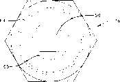
图6是利用一个根据本发明的脊椎校正/固定系统实施例对脊椎骨进行操控和校正的示意图。Figure 6 is a schematic illustration of the manipulation and alignment of the spine using one embodiment of the spine alignment/fixation system in accordance with the present invention.
图7是利用一个根据本发明的脊椎校正/固定系统实施例对脊椎骨进行操控和校正的示意图。Figure 7 is a schematic illustration of the manipulation and alignment of the spine using one embodiment of the spine alignment/fixation system in accordance with the present invention.
对本发明的详细描述Detailed description of the invention
本发明总体涉及一种用于对椎体进行校正和固定的方法及装置。更具体地说,本发明涉及一种系统和方法,其允许外科医生在将椎弓根螺钉插入和固定在椎体内部之后使用安装在半球形椎弓根螺钉上的可自由旋转联结器操控对脊椎校正/固定系统中的固定部件的角度校正。所述系统和方法还被设计成能够通过应用单个固定螺母对角度校正进行固定,并且将校正杆安装和固定到所述联结器上。The present invention generally relates to a method and device for alignment and fixation of a vertebral body. More specifically, the present invention relates to a system and method that allows a surgeon to manipulate a pair of hemispherical pedicle screws using a freely rotatable coupling mounted on a hemispherical pedicle screw after insertion and fixation of the pedicle screw Angle correction of fixed components in chiropractic/fixation systems. The system and method are also designed to be able to fix the angle correction by applying a single set nut, and mount and fix the correction rod to the coupler.
如图1至5中所示,本发明中的脊椎校正/固定装置10由三个主要组件构成:一个半球形椎弓根螺钉12;一个联结元件14,其用作一个万向接头;以及一个固定螺母16。As shown in Figures 1 to 5, the spinal correction/
如图1中所示,半球形椎弓根螺钉12包括一个基本上呈半球形的头部18,一个颈部20以及一个轴部22。尽管在图1中所示出的轴22具有一个总体呈圆柱形的本体24以及一个锥形尖端26,带有一个沿着轴22的长度方向设置的螺纹28,但是任何适合于插入到椎体内部的轴结构、螺距或者尖端锥形均可以在本发明中采用。在图1示出的实施例中,椎弓根螺钉轴22的锥形尖端26还包括一个切槽式沟槽30,其沿着所示轴的纵向进行延伸,被设计成使得所述螺钉能够进行自攻,便于将椎弓根螺钉12插入到椎体之内。As shown in FIG. 1 ,
椎弓根螺钉12的头部18基本上呈半球形。螺钉12的头部18的基本上半球形是一个球体的一部分或者区段。尽管在所示出的实施例中,构成螺钉12的头部18的球体区段或者部分大于半个球体,但是必须明白的是,可以采用任何与头部18的中点等距的外部轮廓。在图1示出的实施例中,基本上呈半球形的头部18的主剖面包括一个至少270度的圆。The
半球形头部18还具有一个位于其上的凹槽32(在图1中以虚线示出)。凹槽32限定出了一个用于从驱动工具33施加转矩的配合位置,用于将螺钉12螺接入骨头之内。凹槽32的具体形状可以被选择成能够与任何适用的螺钉驱动工具33协同工作,如同图4a和4b中示出的那样。例如,凹槽32可以包括用于带有平整头部的螺丝刀的切槽、用于带有菲利普斯式头部的螺丝刀的十字切槽、用于接收通用扳手的六角形孔、或者数字“8”形状的驱动器。在一个优选实施例中,采用了一个用于带有正方形头部的螺丝刀或者插槽式扳手的正方形孔。尽管所示出的凹槽32与螺钉轴22的总体细长轴线同轴,但是必须明白的是,可以采用任何凹槽32与螺钉12的组配方案,以便使得可以在螺钉12上施加足够的转矩,来将其螺接入骨头之内。The
螺钉12的头部18在颈部20处连接在轴部22上。就相互关系而言,轴22的直径必须小于半球形头部18的直径,而螺钉12的颈部20最好必须窄于轴22上的最宽部分。优选的是根据本发明的椎弓根螺钉12具有这种尺寸关系,因为这种螺钉可以相对于联结元件14被锁定在任何角度,同时仍旧被牢固地连接在联结元件14上(其实施例在图1、2和5中示出)。尽管可以采用任何具有合适强度和耐用性的生物适用性材料,但是椎弓根螺钉12最好由外科手术级钛或者不锈钢制成。The
在图1中以侧视图形式示出了本发明中的万向接头式联结元件14的一个示例性实施例,关键元件以虚线示出。联结元件14包括一个总体呈圆柱形的管体,其限定出一个具有内壁36的内部通道34。内部通道34包括一个总体呈圆柱形的上部38和一个向内弯曲的下部40。向内弯曲的下部40限定出一个插槽,螺钉12的头部18可以旋转性地配合入其内。联结元件14的底表面42包括一个开口44,该开口44限定出一条通道46,以便使得螺钉12的轴22可以延伸穿过联结元件14的本体并且穿出其外。为了牢固地将螺钉12配合在联结元件14之内,开口14和通道46的尺寸必须大于螺钉12的轴22的尺寸,但是小于头部18的最大直径。An exemplary embodiment of the universal
联结元件14的圆柱形上部38包括一对竖直方向的通道48,它们具有圆形的底表面50和位于联结元件14的相对侧面上的敞口顶部。以组合方式,通道48形成用于一根细长固定杆60的配合位置。此外,通道48将联结元件14的壁52分成向上延伸元件54和56。如图1、2和5示出的实施例中所示,从通道48的顶部58至弯曲底部50的竖直距离足以允许杆60滑动配合于其中,以便使得杆60可以被完全容置于通道48中。此外,通道48的弯曲底部50被设置成使得在完全容置于插槽下部40中时,螺钉12的头部18的顶部延伸至通道48的弯曲底部50的边缘之上,以便使得位于其中的杆60将与螺钉12的头部18压力配合。联结元件14的上部38的顶部58具有位于其上的螺纹62,上部38包括向上延伸构件54和56。上部38,以及位于其上的螺纹62,非常适合于与固定螺母16螺接配合。The cylindrical
图2a、2b和2c示出了本发明的一个示例性实施例的其余特征,它们允许相对于联结元件14对螺钉12进行至少高达90度的角度校正。在本实施例中,联结元件14的下部40还包括一对下部切槽63,它们从联结元件14的底表面42上的开口44和通道46开始延伸。下部切槽53在联结元件14的底表面42的相对侧面上得以校正,以便使得切槽63以组合方式限定出一条180度的通道,该通道被加工成允许在螺钉头部18完全配合在联结元件14上的插槽40中并且联结元件14被相对于螺钉12上的轴22合适定位时,螺钉12的颈部20移动到其中。如图所示,即使在这种极限角度位置,联结元件14仍然被设计成使得插入到通道48之内的杆60将压靠在螺钉12的头部18上,并且在固定螺母16的压力作用下与杆60和联结元件14发生配合,并且将杆60和联结元件14固定在对齐状态。FIGS. 2 a , 2 b and 2 c show the remaining features of an exemplary embodiment of the invention which allow angular correction of the
在图3a中以俯视图形式、在图3b中以侧视图形式、以及在图3c中以剖视图形式示出了顶部固定螺母16。该螺母16包括一条内螺纹64,用于与联结元件14的上部38中的向上延伸构件54和56上的螺纹62相匹配。螺母16还包括一个内塞部分65,其具有一个底表面66,该底表面66用于座靠在容置于联结元件14中的杆60的顶表面上,提供一个用于向下驱动杆60并且压靠在螺钉12的头部18上的装置。在螺母16的中部设置有一个圆环状的中心开口68,限定出一条贯穿的通道70,该通道70和开口68被设置成能够使得用于将螺钉12螺接入椎体之内的螺钉驱动器可以配合于其中,并且可以被用来将螺母16紧固到联结元件14上,如同图4b中所示出的那样。尽管在图3a至3c中所示出的通道实施例70终止于螺母16上的插塞65的中部,但是通道70也可以横贯插塞65,在开口68与底表面66之间形成一条通路。The
在图1所示出的优选实施例中,螺母16的底表面66还包括大量凸起的金属齿72,它们被设计成与杆60咬入配合并且压入杆60之内,在杆60与脊椎校正装置10之间提供额外的摩擦配合,以便减少由于机械振动导致杆60从脊椎校正装置10中发生松脱的可能性。在另外一个优选实施例中,杆60经过辊筒轧纹或者压纹精整处理,以提高杆60与螺母16的底表面66上的齿72之间的摩擦配合。In the preferred embodiment shown in FIG. 1, the
图4a和4b示出了一个驱动器33与脊椎校正装置10的配合状态,来首先将螺钉12配合入椎体74之内,如同图4a中示出的那样,并且随后将固定螺母16配合到联结元件14上,如同图4b中示出的那样,联结元件14被设计成使得螺钉驱动器33可以配合在联结元件14中的内部通道34之内,并且与螺钉12的头部18上的凹槽32发生配合,来将螺钉12螺接入椎体74之内。如图4b中所示,固定螺母16还被设计成使得螺钉驱动器33可以与螺母16的开口68发生配合,来将螺母16固定在联结元件14上,并且由此将校正杆60固定入联结元件14之内,进一步巩固联结元件14相对于螺钉12的轴线的校正状态。Figures 4a and 4b show the mating state of a
下面参照图5,所示出的联结元件14带有被插入其中的螺钉12,并且螺钉12的头部18被容置在联结元件14的插槽下部中。螺钉12的轴部22被向下插入,穿过联结元件14的内部通道34,并且通过开口44穿出。在该位置处,头部18的弯曲下表面座靠在插槽下部40的向内弯曲底表面42上,并且利用开口44的尺寸防止其进一步向下移动。与此同时,头部18的上表面被压靠在杆60上,其中杆60由固定螺母18压入头部18之内,由此同时防止杆60移出联结元件14并且防止联结元件14相对于螺钉12发生移动。Referring now to FIG. 5 , the
图6和7示出了完全锁定的联结元件、杆和螺钉系统相对于椎体74的关系的侧视图。图6示出了利用一个任选的交联稳定杆将本发明中的脊椎校正/固定装置10以传统方式锚固在多个椎体中。图7示出了利用螺钉12将本发明中的脊椎校正/固定装置10锚固在髂骨(ileumbone)之内,所述螺钉12相对于联结元件14处于90度校正位置。参照这些附图,下面对椎体的优选组装和校正方法进行描述。6 and 7 show side views of a fully locked coupling element, rod and screw system in relation to the
首先,在骨头74中预先钻取一个穿孔76,螺钉12即将被锚固于其内。穿孔76可以被预先攻丝,或者如前所述那样,在螺钉12的尖端部24处的外螺纹28可以包括一个自攻切槽30。在任一种情况下,在组装过程中,螺钉12的尖端26均被插入穿过联结元件14的内部通道34,直至螺钉12的轴22延伸出联结元件14之外,并且螺钉12的头部18配合在联结元件14上的插槽下部40中。此时,在组装过程中,联结元件14能够相对于螺钉12进行旋转。一个螺钉驱动工具33随后与螺钉12的头部18上的凹槽32相对齐,从而使得其可以被螺接入骨头74上的预制穿孔76之内。First, a
在螺钉12已经被螺接入穿孔76的内部之后,所述联结元件可以相对于螺钉12发生旋转,来对联结元件14进行校正,以便使得一根支撑杆60可以配合入杆接收通道48之内,并且根据外科医生的设想合适地得以校正。正如在图5中清楚示出的那样,并且如前所述,杆60的底部座靠在螺钉12的头部18的顶部上,并且没有完全座靠在通道48的弯曲底表面50上。After the
在杆60被置于联结元件14的内部之后,顶部锁定螺母16被螺接在向上延伸元件54和56上的螺纹62上。螺母16随后被向下螺接到联结元件14上,直至螺母16上的配合部分65的下表面66座靠在杆60的顶表面上。随着螺母16下沉到联结元件14上,杆60受到螺母16上的配合部分65的向下驱动,导致杆60与螺钉12的头部18发生配合,并且向下推动螺钉12的头部18,将其压力配合到联结元件14上的插槽40之内。这种向下移动允许杆60的底部座靠在通道48的底表面50上,并且导致螺钉12的头部18被压接锁定在联结元件14的向内弯曲表面40上。所述力还会将螺母16上的齿72配合入杆60之内,在联结元件14与杆60之间提供额外的摩擦配合。由此,由螺母16的底表面66在杆60以及齿72上的向下作用力和由于通道48的底表面50所提供的反作用力会导致杆60得以锁定。这种锁定作用防止了杆60相对于组装好的脊椎校正装置10发生滑动、将杆60锁定在联结元件14上、以及将螺钉12锁定在联结元件14上。After the
除了这些基本组件之外,也可以设置固定部件来将椎骨固定至所需的校正状态。固定部件可以包括夹具,其被设计成与椎弓根螺钉的顶部或者侧面相匹配;可以发生弯曲的固定杆或者板,其在固附于不同椎体上或者固附于同一椎体上不同位置处的各个椎弓根螺钉上的夹具之间延伸;以及螺栓,其也被设计成与所述夹具相匹配,以便使得所述夹具可以被紧固在固定杆上并且将固定杆固定到位。此外,如图6中所示,固定部件可以包括任何结构的交联构件,只要它们适用于对本发明中的校正装置10进行固附即可。例如,尽管在图6中示出的交联构件具有固定尺寸,但是也可以在交联构件上的固定点之间的距离必须改变的应用领域使用带有切槽的交联构件。在一个这样的实施例中,交联构件上用于将其固附到校正装置10的开口(在图6中以简单的穿孔示出)包括细长切槽,以便使得该交联构件可以沿着切槽的长度方向相对于校正装置10发生滑动,由此允许相对于校正装置对交联构件的位置进行某种程度的调节。In addition to these basic components, fixation components may also be provided to fix the vertebrae in the desired alignment. The fixation components may include clamps designed to fit over the top or sides of the pedicle screws; fixation rods or plates that may be bent, which are attached to different vertebral bodies or to different locations on the same vertebral body extending between the clamps on each pedicle screw at ; and bolts, which are also designed to mate with the clamps, so that the clamps can be tightened on the fixation rod and hold the fixation rod in place. In addition, as shown in FIG. 6 , the fixing components may include cross-linking members of any structure, as long as they are suitable for fixing the
所有前述组件,包括所述固定部件,均可以由任何适用于外科手术的材料制成,比如不锈钢或者钛。All the aforementioned components, including the fixation part, may be made of any surgically suitable material, such as stainless steel or titanium.
尽管在此对特定实施例进行了描述,但是应该想到的是,本技术领域中那些熟练技术人员可以并且将会设计出替代性脊椎校正/固定螺钉,它们均落入所附权利要求的保护范围之内,无论是从字面上进行理解或者是遵照等效原则。While specific embodiments have been described herein, it should be appreciated that those skilled in the art can and will devise alternative spinal correction/fixation screws which fall within the scope of the appended claims within, whether taken literally or in accordance with the doctrine of equivalents.
Claims (15)
Applications Claiming Priority (1)
| Application Number | Priority Date | Filing Date | Title |
|---|---|---|---|
| PCT/US2001/041684WO2003015648A1 (en) | 2001-08-13 | 2001-08-13 | Vertebral alignment and fixation assembly |
Publications (2)
| Publication Number | Publication Date |
|---|---|
| CN1547456A CN1547456A (en) | 2004-11-17 |
| CN1255082Ctrue CN1255082C (en) | 2006-05-10 |
Family
ID=21742952
Family Applications (1)
| Application Number | Title | Priority Date | Filing Date |
|---|---|---|---|
| CN01823649.9AExpired - Fee RelatedCN1255082C (en) | 2001-08-13 | 2001-08-13 | Chiropractic Correction and Immobilization Devices |
Country Status (6)
| Country | Link |
|---|---|
| EP (1) | EP1418853B1 (en) |
| CN (1) | CN1255082C (en) |
| AT (1) | ATE498366T1 (en) |
| CA (1) | CA2456892A1 (en) |
| DE (1) | DE60144067D1 (en) |
| WO (1) | WO2003015648A1 (en) |
Families Citing this family (9)
| Publication number | Priority date | Publication date | Assignee | Title |
|---|---|---|---|---|
| US7377923B2 (en) | 2003-05-22 | 2008-05-27 | Alphatec Spine, Inc. | Variable angle spinal screw assembly |
| EP1527742B1 (en)* | 2003-10-31 | 2006-07-26 | Spinelab AG | Locking cap for pedicle screws for fixing of elastic rods |
| US7214227B2 (en) | 2004-03-22 | 2007-05-08 | Innovative Spinal Technologies | Closure member for a medical implant device |
| US7338491B2 (en)* | 2005-03-22 | 2008-03-04 | Spinefrontier Inc | Spinal fixation locking mechanism |
| CH705709B1 (en) | 2005-08-29 | 2013-05-15 | Bird Biedermann Ag | Spinal implant. |
| US20140018867A1 (en)* | 2011-02-04 | 2014-01-16 | Stefan Freudiger | Precaution against jamming on open bone screws |
| WO2016170199A1 (en)* | 2015-04-23 | 2016-10-27 | Sanpera Trigueros Ignacio | Fixation system for spinal instrumentation |
| CN116212227B (en)* | 2022-12-28 | 2024-03-08 | 心擎医疗(苏州)股份有限公司 | Ventricular assist catheter pump |
| WO2025045603A1 (en)* | 2023-08-25 | 2025-03-06 | Icotec Ag | Medical bone connection device and method for connecting bones or bone parts |
Family Cites Families (8)
| Publication number | Priority date | Publication date | Assignee | Title |
|---|---|---|---|---|
| DE4307576C1 (en)* | 1993-03-10 | 1994-04-21 | Biedermann Motech Gmbh | Bone screw esp. for spinal column correction - has U=shaped holder section for receiving straight or bent rod |
| US5882350A (en)* | 1995-04-13 | 1999-03-16 | Fastenetix, Llc | Polyaxial pedicle screw having a threaded and tapered compression locking mechanism |
| US5964760A (en)* | 1996-10-18 | 1999-10-12 | Spinal Innovations | Spinal implant fixation assembly |
| US5728098A (en)* | 1996-11-07 | 1998-03-17 | Sdgi Holdings, Inc. | Multi-angle bone screw assembly using shape-memory technology |
| US5782833A (en)* | 1996-12-20 | 1998-07-21 | Haider; Thomas T. | Pedicle screw system for osteosynthesis |
| US6010503A (en)* | 1998-04-03 | 2000-01-04 | Spinal Innovations, Llc | Locking mechanism |
| DE19936286C2 (en) | 1999-08-02 | 2002-01-17 | Lutz Biedermann | bone screw |
| US6280442B1 (en)* | 1999-09-01 | 2001-08-28 | Sdgi Holdings, Inc. | Multi-axial bone screw assembly |
- 2001
- 2001-08-13ATAT01966681Tpatent/ATE498366T1/ennot_activeIP Right Cessation
- 2001-08-13DEDE60144067Tpatent/DE60144067D1/ennot_activeExpired - Lifetime
- 2001-08-13EPEP01966681Apatent/EP1418853B1/ennot_activeExpired - Lifetime
- 2001-08-13CNCN01823649.9Apatent/CN1255082C/ennot_activeExpired - Fee Related
- 2001-08-13WOPCT/US2001/041684patent/WO2003015648A1/enactiveApplication Filing
- 2001-08-13CACA002456892Apatent/CA2456892A1/ennot_activeAbandoned
Also Published As
| Publication number | Publication date |
|---|---|
| CA2456892A1 (en) | 2003-02-27 |
| EP1418853A1 (en) | 2004-05-19 |
| EP1418853A4 (en) | 2008-10-15 |
| CN1547456A (en) | 2004-11-17 |
| WO2003015648A1 (en) | 2003-02-27 |
| EP1418853B1 (en) | 2011-02-16 |
| ATE498366T1 (en) | 2011-03-15 |
| DE60144067D1 (en) | 2011-03-31 |
Similar Documents
| Publication | Publication Date | Title |
|---|---|---|
| US6981973B2 (en) | Low profile vertebral alignment and fixation assembly | |
| US6520963B1 (en) | Vertebral alignment and fixation assembly | |
| US20230190336A1 (en) | Modular uniplanar pedicle screw assembly for use with a polyaxial bone fastener | |
| US9827014B2 (en) | Modular pedicle screw system | |
| AU2001247388B2 (en) | Multi-axial bone anchor system | |
| US7682379B2 (en) | Device for osteosynthesis | |
| US8926669B2 (en) | Modular polyaxial pedicle screw system | |
| CA2237240C (en) | Spinal fixation plate | |
| AU2014234156B2 (en) | Spinal implant assembly | |
| US9101401B2 (en) | Bone repair device and method | |
| US20100131017A1 (en) | Multi-Axial Bone Anchor Assembly | |
| US20100191290A1 (en) | Spinal stabilizing system | |
| AU2001247388A1 (en) | Multi-axial bone anchor system | |
| EP1962706A1 (en) | Polyaxial bone anchor with headless pedicle screw | |
| CN1255082C (en) | Chiropractic Correction and Immobilization Devices | |
| US20240423681A1 (en) | Orthopedic fixation devices and methods thereof | |
| WO2005018470A1 (en) | Low profile vertebral alignment and fixation assembly | |
| AU2001287172A1 (en) | Vertebral alignment and fixation assembly |
Legal Events
| Date | Code | Title | Description |
|---|---|---|---|
| C06 | Publication | ||
| PB01 | Publication | ||
| C10 | Entry into substantive examination | ||
| SE01 | Entry into force of request for substantive examination | ||
| C14 | Grant of patent or utility model | ||
| GR01 | Patent grant | ||
| CF01 | Termination of patent right due to non-payment of annual fee | Granted publication date:20060510 Termination date:20180813 | |
| CF01 | Termination of patent right due to non-payment of annual fee |