CN1238705A - multi-lumen channel device - Google Patents
multi-lumen channel deviceDownload PDFInfo
- Publication number
- CN1238705A CN1238705ACN97180103ACN97180103ACN1238705ACN 1238705 ACN1238705 ACN 1238705ACN 97180103 ACN97180103 ACN 97180103ACN 97180103 ACN97180103 ACN 97180103ACN 1238705 ACN1238705 ACN 1238705A
- Authority
- CN
- China
- Prior art keywords
- multiple lumen
- lumen access
- lumen
- access according
- device chamber
- Prior art date
- Legal status (The legal status is an assumption and is not a legal conclusion. Google has not performed a legal analysis and makes no representation as to the accuracy of the status listed.)
- Granted
Links
Images


Classifications
- A—HUMAN NECESSITIES
- A61—MEDICAL OR VETERINARY SCIENCE; HYGIENE
- A61M—DEVICES FOR INTRODUCING MEDIA INTO, OR ONTO, THE BODY; DEVICES FOR TRANSDUCING BODY MEDIA OR FOR TAKING MEDIA FROM THE BODY; DEVICES FOR PRODUCING OR ENDING SLEEP OR STUPOR
- A61M25/00—Catheters; Hollow probes
- A—HUMAN NECESSITIES
- A61—MEDICAL OR VETERINARY SCIENCE; HYGIENE
- A61B—DIAGNOSIS; SURGERY; IDENTIFICATION
- A61B17/00—Surgical instruments, devices or methods
- A61B17/34—Trocars; Puncturing needles
- A61B17/3417—Details of tips or shafts, e.g. grooves, expandable, bendable; Multiple coaxial sliding cannulas, e.g. for dilating
- A—HUMAN NECESSITIES
- A61—MEDICAL OR VETERINARY SCIENCE; HYGIENE
- A61B—DIAGNOSIS; SURGERY; IDENTIFICATION
- A61B17/00—Surgical instruments, devices or methods
- A61B17/34—Trocars; Puncturing needles
- A61B17/3498—Valves therefor, e.g. flapper valves, slide valves
- A—HUMAN NECESSITIES
- A61—MEDICAL OR VETERINARY SCIENCE; HYGIENE
- A61B—DIAGNOSIS; SURGERY; IDENTIFICATION
- A61B17/00—Surgical instruments, devices or methods
- A61B17/34—Trocars; Puncturing needles
- A61B17/3417—Details of tips or shafts, e.g. grooves, expandable, bendable; Multiple coaxial sliding cannulas, e.g. for dilating
- A61B17/3421—Cannulas
- A61B2017/3445—Cannulas used as instrument channel for multiple instruments
- A—HUMAN NECESSITIES
- A61—MEDICAL OR VETERINARY SCIENCE; HYGIENE
- A61B—DIAGNOSIS; SURGERY; IDENTIFICATION
- A61B17/00—Surgical instruments, devices or methods
- A61B17/34—Trocars; Puncturing needles
- A61B17/3462—Trocars; Puncturing needles with means for changing the diameter or the orientation of the entrance port of the cannula, e.g. for use with different-sized instruments, reduction ports, adapter seals
- A61B2017/3466—Trocars; Puncturing needles with means for changing the diameter or the orientation of the entrance port of the cannula, e.g. for use with different-sized instruments, reduction ports, adapter seals for simultaneous sealing of multiple instruments
- A—HUMAN NECESSITIES
- A61—MEDICAL OR VETERINARY SCIENCE; HYGIENE
- A61M—DEVICES FOR INTRODUCING MEDIA INTO, OR ONTO, THE BODY; DEVICES FOR TRANSDUCING BODY MEDIA OR FOR TAKING MEDIA FROM THE BODY; DEVICES FOR PRODUCING OR ENDING SLEEP OR STUPOR
- A61M25/00—Catheters; Hollow probes
- A61M25/0021—Catheters; Hollow probes characterised by the form of the tubing
- A61M25/0023—Catheters; Hollow probes characterised by the form of the tubing by the form of the lumen, e.g. cross-section, variable diameter
- A61M25/0026—Multi-lumen catheters with stationary elements
- A61M2025/0034—Multi-lumen catheters with stationary elements characterized by elements which are assembled, connected or fused, e.g. splittable tubes, outer sheaths creating lumina or separate cores
- A—HUMAN NECESSITIES
- A61—MEDICAL OR VETERINARY SCIENCE; HYGIENE
- A61M—DEVICES FOR INTRODUCING MEDIA INTO, OR ONTO, THE BODY; DEVICES FOR TRANSDUCING BODY MEDIA OR FOR TAKING MEDIA FROM THE BODY; DEVICES FOR PRODUCING OR ENDING SLEEP OR STUPOR
- A61M25/00—Catheters; Hollow probes
- A61M25/0021—Catheters; Hollow probes characterised by the form of the tubing
- A61M25/0023—Catheters; Hollow probes characterised by the form of the tubing by the form of the lumen, e.g. cross-section, variable diameter
- A61M25/0026—Multi-lumen catheters with stationary elements
- A61M2025/0035—Multi-lumen catheters with stationary elements characterized by a variable lumen cross-section by means of a resilient flexible septum or outer wall
- A—HUMAN NECESSITIES
- A61—MEDICAL OR VETERINARY SCIENCE; HYGIENE
- A61M—DEVICES FOR INTRODUCING MEDIA INTO, OR ONTO, THE BODY; DEVICES FOR TRANSDUCING BODY MEDIA OR FOR TAKING MEDIA FROM THE BODY; DEVICES FOR PRODUCING OR ENDING SLEEP OR STUPOR
- A61M25/00—Catheters; Hollow probes
- A61M25/0021—Catheters; Hollow probes characterised by the form of the tubing
- A61M25/0023—Catheters; Hollow probes characterised by the form of the tubing by the form of the lumen, e.g. cross-section, variable diameter
- A61M25/0026—Multi-lumen catheters with stationary elements
- A61M2025/0036—Multi-lumen catheters with stationary elements with more than four lumina
- A—HUMAN NECESSITIES
- A61—MEDICAL OR VETERINARY SCIENCE; HYGIENE
- A61M—DEVICES FOR INTRODUCING MEDIA INTO, OR ONTO, THE BODY; DEVICES FOR TRANSDUCING BODY MEDIA OR FOR TAKING MEDIA FROM THE BODY; DEVICES FOR PRODUCING OR ENDING SLEEP OR STUPOR
- A61M25/00—Catheters; Hollow probes
- A61M25/0021—Catheters; Hollow probes characterised by the form of the tubing
- A61M25/0023—Catheters; Hollow probes characterised by the form of the tubing by the form of the lumen, e.g. cross-section, variable diameter
- A61M25/0026—Multi-lumen catheters with stationary elements
- A61M25/0032—Multi-lumen catheters with stationary elements characterized by at least one unconventionally shaped lumen, e.g. polygons, ellipsoids, wedges or shapes comprising concave and convex parts
- A—HUMAN NECESSITIES
- A61—MEDICAL OR VETERINARY SCIENCE; HYGIENE
- A61M—DEVICES FOR INTRODUCING MEDIA INTO, OR ONTO, THE BODY; DEVICES FOR TRANSDUCING BODY MEDIA OR FOR TAKING MEDIA FROM THE BODY; DEVICES FOR PRODUCING OR ENDING SLEEP OR STUPOR
- A61M25/00—Catheters; Hollow probes
- A61M25/0067—Catheters; Hollow probes characterised by the distal end, e.g. tips
- A61M25/0074—Dynamic characteristics of the catheter tip, e.g. openable, closable, expandable or deformable
- A61M25/0075—Valve means
- A—HUMAN NECESSITIES
- A61—MEDICAL OR VETERINARY SCIENCE; HYGIENE
- A61M—DEVICES FOR INTRODUCING MEDIA INTO, OR ONTO, THE BODY; DEVICES FOR TRANSDUCING BODY MEDIA OR FOR TAKING MEDIA FROM THE BODY; DEVICES FOR PRODUCING OR ENDING SLEEP OR STUPOR
- A61M25/00—Catheters; Hollow probes
- A61M25/01—Introducing, guiding, advancing, emplacing or holding catheters
- A61M25/06—Body-piercing guide needles or the like
- A61M25/0662—Guide tubes
- A61M25/0668—Guide tubes splittable, tear apart
Landscapes
- Health & Medical Sciences (AREA)
- Life Sciences & Earth Sciences (AREA)
- Public Health (AREA)
- Veterinary Medicine (AREA)
- Animal Behavior & Ethology (AREA)
- Engineering & Computer Science (AREA)
- Biomedical Technology (AREA)
- Heart & Thoracic Surgery (AREA)
- Surgery (AREA)
- General Health & Medical Sciences (AREA)
- Medical Informatics (AREA)
- Hematology (AREA)
- Pathology (AREA)
- Nuclear Medicine, Radiotherapy & Molecular Imaging (AREA)
- Molecular Biology (AREA)
- Pulmonology (AREA)
- Anesthesiology (AREA)
- Biophysics (AREA)
- Infusion, Injection, And Reservoir Apparatuses (AREA)
- Media Introduction/Drainage Providing Device (AREA)
- Ultra Sonic Daignosis Equipment (AREA)
- External Artificial Organs (AREA)
- Surgical Instruments (AREA)
- Separation By Low-Temperature Treatments (AREA)
- Magnetic Resonance Imaging Apparatus (AREA)
Abstract
Translated fromChinese
Description
Translated fromChinese技术背景technical background
技术领域technical field
本发明整体涉及用来提供进入人体内的通道的医疗装置。本发明尤其针对用于提供简单、相对长期的进入人体入口的通道装置。在活体诊断测试和/或治疗过程中,入口供医生和其他医务人员用来选择性地将多种医疗器械引入人体。The present invention generally relates to medical devices for providing access into the human body. The present invention is particularly directed to access devices for providing simple, relatively long-term access to the human body. Portals are used by physicians and other medical personnel to selectively introduce various medical devices into the body during biodiagnostic testing and/or treatment.
相关技术描述Related technical description
近年来发展了很多种提供进入人体血流内的通道的医疗装置。根据其功能和目的,这些装置通常可分为两个不同的组。第一组装置包括为将治疗和/或诊断流体引入血流而设计的导管。第二组包括通常称为“导引管”的装置,为提供进入人体的通道入口而设计,为治疗和/或诊断的目的可从此口通入多种医疗器械。In recent years a variety of medical devices have been developed that provide access to the bloodstream of the human body. Depending on their function and purpose, these devices can generally be divided into two distinct groups. The first group of devices includes catheters designed to introduce therapeutic and/or diagnostic fluids into the bloodstream. The second group includes devices commonly referred to as "guide tubes" designed to provide access to the body through which a variety of medical devices may be passed for therapeutic and/or diagnostic purposes.
主静脉导管是带有锥形未端的较长的管状装置,为进入主静脉而设计,以便为流体注入人体提供一条专用通道。最初的静脉导管是单腔装置,提供了每次将一种液体注入静脉的功能。其后发展了多腔导管,允许将两种或多种液体同时引入静脉。导管留在人体外面的部分被不断地改善和重新设计,以给出不很显眼的外形,从而增加舒适性并降低了退出人身的专用管子所带来的不雅观的程度。主静脉压力导管是一种普通多腔导管,在监测血压和其他重要参数的同时,其允许同时引入和排出多种流体。A main venous catheter is a long, tubular device with a tapered end designed to enter a main vein to provide a dedicated path for fluids into the body. The original IV catheters were single-lumen devices that provided for the infusion of one fluid into the vein at a time. Multilumen catheters have since been developed, allowing simultaneous introduction of two or more fluids into the vein. The portion of the catheter that remains outside the body is continually improved and redesigned to give it a low profile profile, thereby increasing comfort and reducing the degree of unsightliness associated with specialized tubes exiting the body. A main venous pressure catheter is a common multilumen catheter that allows the simultaneous introduction and removal of multiple fluids while monitoring blood pressure and other important parameters.
导引管在设计和目的方面都和导管有很大不同。导引管是一种用于提供进入人体的专用通道口的通道装置。而导管则是用于将流体注入或排出人体的。导引管一般包括一个较短的腔,各种医疗器械包括导管在内可通过该腔被选择性地引入人体或从人体中撤出。任何导引管的重要特征是阀门总成。当医疗器械被引入和从人体撤出时,阀门总成在血流和体外环境之间提供恒定的密封。阀门总成一般位于人体外部的导引管近端。因此,导引管近端总是较为粗大。Introducers are very different from catheters in both design and purpose. A guide tube is a channel device used to provide a dedicated access port into the body. Catheters are used to get fluids into or out of the body. Guide tubes generally include a relatively short lumen through which various medical devices, including catheters, can be selectively introduced into or withdrawn from the body. An important feature of any pilot tube is the valve assembly. The valve assembly provides a constant seal between the blood flow and the extracorporeal environment as the medical device is introduced and withdrawn from the body. The valve assembly is generally located at the proximal end of the guide tube outside the human body. Therefore, the proximal end of the guide tube is always thicker.
除了阀门总成,许多导引管近端还包括一个侧臂。该侧壁与腔相连,使得流体能和医疗装置一起被引入人体。导引管腔被看作是一个“共享”腔,因为该腔为医疗器械和药或诊断用流体提供了一个共同的导管。In addition to the valve assembly, many introducer tubes include a side arm at the proximal end. The sidewall is connected to the lumen so that fluid can be introduced into the body along with the medical device. The guide lumen is considered a "shared" lumen because it provides a common conduit for medical devices and pharmaceutical or diagnostic fluids.
现有导引管和其他通道装置非常适合于其预期目的。然而,新的医学治疗和诊断方法在不断地发展,这要求更通用的进入人体的通道。比如,器官移植和心脏搭脉需要将复杂的医疗器械和诊断/治疗流体的组合引入人体。许多现有通道装置不很适合于这些相对复杂的过程。因此,在必须使用多通道的场合,需要多通道装置。所以,提供改善的通道装置有着不断的需求,其带有传统的功能同时增加了通用性和有用性,以用于种类越来越多的侵染性治疗及过程。Existing guide tubes and other channel devices are well suited for their intended purpose. However, new medical treatments and diagnostics are constantly being developed, requiring more versatile access to the human body. For example, organ transplants and heart bypasses require the introduction of complex combinations of medical devices and diagnostic/therapeutic fluids into the body. Many existing channel devices are not well suited for these relatively complex processes. Therefore, where multiple channels must be used, multi-channel devices are required. Therefore, there is a continuing need to provide improved access devices with traditional functionality while increasing versatility and usefulness for an increasing variety of invasive treatments and procedures.
发明概述Summary of the invention
根据本发明,提供了一种改进的通道装置,用于将医疗器械选择性地引入人体,同时通过专用多重管腔提供辅助通道。本发明是对现有导引管和其他通道装置的一种改进,除了用于医疗器械和诊断用流体的共享腔外,还通过导引管提供了多腔通道。改进通道装置的好处是:在复杂的外科手术和诊断过程中,减少了将多种器械和流体引入人体所需的装置数目。In accordance with the present invention, an improved access device is provided for the selective introduction of medical devices into the body while providing auxiliary access through dedicated multiple lumens. The present invention is an improvement over existing guide tubes and other access devices by providing a multi-lumen channel through the guide tube in addition to a shared lumen for medical instruments and diagnostic fluids. A benefit of the improved access device is that it reduces the number of devices required to introduce multiple instruments and fluids into the body during complex surgical and diagnostic procedures.
本发明令人满意地包括了一个提供进入人体入口的多腔通道系统,用于选择性地引入医疗器械并同时提供进入人体的辅助通道。该系统包括一个多腔通道装置,其包括一个带有引入到人体的远端和一个留在人体外部的近端的外管,该外管带有一个外表面。在外表面中形成一个装置腔,其中可通过医疗器械;装置腔带有一个远端和一个近端。在外表面中至少形成一个辅助腔,并和装置腔分开;辅助腔带有一个远端和一个近端。最后,在装置腔的近端有一个装置腔阀门,当医疗器械位于和离开装置腔时,起密封装置腔的作用。The present invention desirably includes a multi-lumen channel system providing access to the body for selective introduction of medical devices while providing secondary access to the body. The system includes a multilumen channel device including an outer tube with a distal end that is introduced into the body and a proximal end that remains outside the body, the outer tube having an outer surface. A device cavity is formed in the outer surface through which the medical instrument can pass; the device cavity has a distal end and a proximal end. At least one auxiliary lumen is formed in the outer surface separate from the device lumen; the auxiliary lumen has a distal end and a proximal end. Finally, there is a device chamber valve at the proximal end of the device chamber that acts to seal the device chamber when the medical device is in and out of the device chamber.
根据本发明的多腔通道系统还可包括一个带有近端和远端的连接壳,其远端与外管的近端相连。连接壳包括一个与装置腔交换流体的主管道以及至少一个与至少一个辅助腔交换流体的辅助管道;主管道和辅助管道从外管处分开,在连接壳中不相互交叉。The multi-lumen channel system according to the present invention may also include a connecting shell with a proximal end and a distal end, the distal end of which is connected to the proximal end of the outer tube. The connecting shell includes a main pipe for exchanging fluid with the device chamber and at least one auxiliary pipe for exchanging fluid with at least one auxiliary chamber; the main pipe and the auxiliary pipe are separated from the outer tube and do not intersect each other in the connecting shell.
在一个实施例中,提供了装置腔阀门作为连接壳的一部分,并与主管道进行流体交换。在连接壳中可形成一个装置管道,与主管道成一角度并终止于内端,和主管道进行流体交换。装置腔阀门位于装置管道的外端,使得医疗装置可以被插入并以一角度进入主管道。主管道可令人满意地从连接壳远端通过装置腔延续到连接壳的开口处,使其中的流体能引入主管道。在一个实施例中,装置腔阀门以一种比连接壳更硬的材料和连接壳分开塑成,并通过插入形成于连接壳中的空腔和多腔通道装置装配在一起。In one embodiment, a device chamber valve is provided as part of the connection housing and in fluid communication with the main conduit. A device conduit may be formed in the connection housing, angled to the main conduit and terminating at an inner end, in fluid communication with the main conduit. The device chamber valve is located at the outer end of the device conduit so that the medical device can be inserted and angled into the main conduit. The main conduit may desirably continue from the distal end of the connection housing through the device cavity to an opening in the connection housing such that fluid therein can be introduced into the main conduit. In one embodiment, the device chamber valve is molded separately from the connection housing from a material harder than the connection housing, and assembled by inserting the cavity formed in the connection housing and the multi-chamber channel device.
在另一种实施例中,连接壳的主管道和辅助管道可定位得基本共面,这样连接壳基本是平的;系统进一步包括一个从连接壳近端延伸出来的延伸管,与主管道交换流体,其中装置腔阀门与延伸管相连,因此可与主管道交换流体。在装置腔阀门中可提供一个侧面端口,使流体能够被注入延伸管和主管道。此外,在装置腔阀门和延伸管之间可包括带有配对螺纹的连接器,使得装置腔阀门容易被拆除。最后,在装置腔阀门上可提供一个路厄氏(luer)连接器,该系统包括一个带有配对路厄氏(luer)连接器的注射器。In another embodiment, the main conduit and the auxiliary conduit of the connecting shell can be positioned substantially coplanar so that the connecting shell is substantially flat; the system further includes an extension tube extending from the proximal end of the connecting shell to exchange with the main conduit Fluid, where the device cavity valve is connected to the extension tube so that fluid can be exchanged with the main pipeline. A side port may be provided in the device chamber valve to allow fluid to be injected into the extension and main tubing. Additionally, a connector with mating threads may be included between the device chamber valve and the extension tube to allow easy removal of the device chamber valve. Finally, a luer connector can be provided on the device chamber valve, and the system includes a syringe with a mating luer connector.
在另一个实施例中,本发明针对这样的多腔通道装置:其可包括一个外管,外管带有一个用于引入到人体的远端和一个留在体外的近端。外管可带有一个外表面和一个内表面,内表面限定一个进入通道,在外管的远端和近端之间的不同位置,该通道的截面积可以变化。装置腔位于通道中,也包括一个远端和一个近端。装置腔由一个带有一外表面和一内表面的内管所形成。内表面限定了医疗器械可从中通过的装置腔。至少一个辅助腔位于内管的外表面和外管的内表面之间。此外,根据本发明的多腔装置包括一个安装于装置腔近端的装置腔阀门,当医疗器械存在和撤走时,都可将装置腔密封。In another embodiment, the present invention is directed to a multi-lumen access device that may include an outer tube with a distal end for introduction into the body and a proximal end that remains outside the body. The outer tube may have an outer surface and an inner surface, the inner surface defining an access channel whose cross-sectional area may vary at different locations between the distal and proximal ends of the outer tube. A device lumen is located in the channel and also includes a distal end and a proximal end. The device lumen is defined by an inner tube having an outer surface and an inner surface. The inner surface defines a device lumen through which a medical instrument may pass. At least one auxiliary lumen is located between the outer surface of the inner tube and the inner surface of the outer tube. Additionally, the multi-chamber device according to the present invention includes a device chamber valve mounted proximally to the device chamber to seal the device chamber both during the presence and withdrawal of the medical device.
作为本发明的一个更理想的特征,内管具有足够的弹性,可从一个放松位置和扩张或收缩位置移动,其中装置腔在放松位置有一个第一截面积,在扩张或收缩位置中装置腔或通道有比第一截面积大或小、且比通道截面积小的截面积。内管具有柔韧性的有利之处是:允许插入各种带有不同截面积的医疗器械。这种柔韧性允许辅助腔和装置腔的截面积和相应的流体可能流速按需要去控制,并达到最佳化。As a more desirable feature of the present invention, the inner tube is sufficiently elastic to move from a relaxed position in which the device lumen has a first cross-sectional area and an expanded or contracted position in which the device lumen Or the channel has a cross-sectional area larger or smaller than the first cross-sectional area and smaller than the channel cross-sectional area. The advantage of the flexibility of the inner tube is that it allows the insertion of various medical devices with different cross-sectional areas. This flexibility allows the cross-sectional areas of the auxiliary and device chambers and the corresponding possible fluid flow rates to be controlled and optimized as desired.
本发明的另一个特征是,提供了两个或更多个辅助通道,这些通道由外管的内表面、内管的外表面和分隔表面所限定,分隔表面在辅助腔之间提供了分隔的阻挡层。两个或更多个辅助通道的提供,允许在通过装置腔引入一种医疗器械的同时,引入另外的诊断或治疗液体。还描述了提供单一辅助腔的本发明实施例。Another feature of the invention is the provision of two or more auxiliary passages defined by the inner surface of the outer tube, the outer surface of the inner tube and a dividing surface that provides a separate space between the auxiliary lumens. barrier layer. The provision of two or more auxiliary channels allows the introduction of additional diagnostic or therapeutic fluids simultaneously with the introduction of a medical device through the lumen of the device. Embodiments of the invention providing a single auxiliary lumen are also described.
作为本发明另外一个特征,在外管的内表面和/或内管的内表面上提供了分隔肋。分隔肋位于辅助腔内;在较大的医疗器械插入装置腔过程中,可防止腔完全闭合。位于内管内表面上的分隔肋,可确保在位于装置腔中的装置周围有一个通道。As another feature of the invention, dividing ribs are provided on the inner surface of the outer tube and/or the inner surface of the inner tube. Separator ribs are located within the auxiliary lumen; during insertion of larger medical devices into the lumen of the device, they prevent the lumen from fully closing. Divider ribs located on the inner surface of the inner tube ensure a passage around the device located in the device cavity.
本发明的上述及许多其他特征和相应优点,可从下列结合附图的详细描述中更好地得到理解。The above and many other features and corresponding advantages of the present invention can be better understood from the following detailed description taken in conjunction with the accompanying drawings.
附图说明Description of drawings
图1是一个根据本发明的示范优选多腔通道装置的透视图。Figure 1 is a perspective view of an exemplary preferred multilumen access device according to the present invention.
图2是图1沿2-2平面处的截面图。Fig. 2 is a cross-sectional view of Fig. 1 along the 2-2 plane.
图3A是图1沿相同的2-2平面处的截面图,其显示了位于装置腔中的一个较小直径的医疗装置。Fig. 3A is a cross-sectional view along the same 2-2 plane of Fig. 1 showing a smaller diameter medical device in the device lumen.
图3B是图1沿相同的2-2平面处的截面图,其显示了位于装置腔中的一个较大直径的医疗装置。3B is a cross-sectional view along the same 2-2 plane of FIG. 1 showing a larger diameter medical device in the device lumen.
图4是图1沿4-4平面处的截面图。Fig. 4 is a cross-sectional view along the 4-4 plane of Fig. 1 .
图5是图1沿5-5平面处的截面图。Fig. 5 is a cross-sectional view along the 5-5 plane of Fig. 1 .
图6是一个根据本发明的优选示范实施例的透视图。Fig. 6 is a perspective view of a preferred exemplary embodiment according to the present invention.
图7是图6沿7-7平面处的截面图。Fig. 7 is a cross-sectional view of Fig. 6 along plane 7-7.
图8是图6沿8-8平面处的截面图。Fig. 8 is a cross-sectional view of Fig. 6 along the 8-8 plane.
图9是一个优选示范弹性内壁的截面图,显示了分隔肋的位置。Figure 9 is a cross-sectional view of a preferred exemplary resilient inner wall showing the location of the divider ribs.
图10是一个带有单一辅助腔的优选示范多腔通道装置的截面图。Figure 10 is a cross-sectional view of a preferred exemplary multi-lumen access device with a single auxiliary lumen.
图11是一个示范多腔通道装置的截面图,显示了处于放松状态的内壁,一个较小直径的医疗器械置于其中。Figure 11 is a cross-sectional view of an exemplary multi-lumen access device showing the inner walls in a relaxed state with a smaller diameter medical device positioned therein.
图12是同一多腔通道装置和医疗器械的截面图,显示了内壁由于辅助腔压力而部分内陷。Figure 12 is a cross-sectional view of the same multi-lumen access device and medical device showing partial invagination of the inner walls due to pressure in the auxiliary lumen.
图13是图11中同一多腔通道装置和医疗器械的截面图,和图12相比,显示的内管处于更完全内陷的状态。Fig. 13 is a cross-sectional view of the same multi-lumen access device and medical device of Fig. 11, showing the inner tube in a more fully invaginated state compared to Fig. 12 .
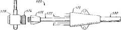
图14是另一个根据本发明的多腔通道装置实施例的透视图。Figure 14 is a perspective view of another embodiment of a multi-lumen access device according to the present invention.
图15是图14沿15-15平面处的截面图。Fig. 15 is a cross-sectional view of Fig. 14 along the 15-15 plane.
图16是图14所示装置的连接壳的放大透视图。FIG. 16 is an enlarged perspective view of a connection case of the device shown in FIG. 14 .
图17是图16中连接壳的放大透视图,切去了纵轴方向的一部分。Fig. 17 is an enlarged perspective view of the connecting shell in Fig. 16, with a part cut away in the direction of the longitudinal axis.
图18是图16中连接壳使用的阀门插入件的装配透视图。FIG. 18 is an assembled perspective view of the valve insert used with the connection housing of FIG. 16. FIG.
图19是图18中阀门插入件的分解透视图。FIG. 19 is an exploded perspective view of the valve insert of FIG. 18. FIG.
图20是一个根据本发明的多腔通道装置的正视图。Figure 20 is a front view of a multi-lumen access device according to the present invention.
图21是图20中多腔通道装置的平面视图,显示了有关导管系统的更多细节。Figure 21 is a plan view of the multilumen access device of Figure 20 showing more detail about the catheter system.
图22是图20装置隐蔽外形连接壳的近端透视图。Figure 22 is a proximal perspective view of the concealed profile connection shell of the device of Figure 20 .
图23是另一个带有不显眼外形连接壳的多腔通道装置的平面图。Figure 23 is a plan view of another multi-lumen access device with a discreetly contoured connection shell.
图24是另一个用于图21或23装置的导引管阀门总成的详细视图。Figure 24 is a detailed view of another pilot tube valve assembly for use with the device of Figures 21 or 23.
图25是另一个替代多腔通道装置的平面视图,带有一个与单腔导引管对接的多腔注入导管。Figure 25 is a plan view of another alternative multi-lumen access device with a multi-lumen infusion catheter interfaced with a single-lumen guide tube.
图26是用于图25中装置的连接壳的截面图。FIG. 26 is a cross-sectional view of a connection case for the device of FIG. 25. FIG.
图27a-d是用于图25中多腔注入导管的套管/腔结构的示意性截面图。27a-d are schematic cross-sectional views of the cannula/lumen configuration for the multi-lumen infusion catheter of FIG. 25 .
图28是用于图25装置的另一个多腔套管实施例的正视图。Figure 28 is an elevational view of another embodiment of a multi-lumen cannula for use with the device of Figure 25 .
图29是图28中多腔套管的截面图。Figure 29 is a cross-sectional view of the multi-lumen sleeve of Figure 28 .
优选实施例描述Description of preferred embodiments
图1-5整体以10指示了一个根据本发明的优选示范多腔通道装置(MLAD)。装置10包括一个具有远端14和近端16的外管12。外管12有一个外表面18和一个内表面20,最好地显示于图2-5中。内表面20限定了一个通道或腔22,在外管12的远端14和近端16之间的不同位置,其截面积可以变化。如果需要,外管12的远端14一般可成锥形。作为外管12成锥形的结果,截面积将逐渐减小。Figures 1-5 generally indicate at 10 a preferred exemplary multi-lumen access device (MLAD) according to the present invention.
根据本发明,一个内管24位于通道22中。内管24有与外管12的远端14和近端16相应的远端和近端。内管24包括一个外表面26和一个内表面28。内表面28限定了一个装置腔30,医疗器械(如分别示于图3A和3B中的导管32和34)可通过装置腔插入人体。导管34还显示于图4和5装置腔30中的合适位置。According to the invention, an
两个辅助腔36和48位于内管24的外表面26和外管12的内表面20之间。每个辅助腔36和48都有与外管12和内管24的远端和近端整体相对应的一个远端和一个近端。在此特定优选实施例中,限定辅助腔36和48的表面相应于外管的内表面和内管的外表面部分。具体来说,辅助腔36由内表面38所限定或作为边缘,其对应于外管12的内表面20和内管24的外表面26。此外,辅助腔36通过分隔面40和42来限定,分隔阻挡层44和46分别形成分隔面40和42。Two
第二辅助腔48也由外管12的内表面20和内管24的外表面26所形成或限定。因此,限定第二辅助腔48的内表面50也对应于这些表面。此外,辅助腔48以分隔阻挡层44和46分别形成的分隔面52和54为边缘。The second
参考图1,多腔通道装置10包括一个连接壳56。连接壳56与通道腔12的近端16相连接。壳56包括注入管道58和60,其通过壳56分别与辅助腔36和48相连。注入管道58和60包括路厄氏(luer)连接器62和64。可以使用其他传统的连接器装置。第三注入管道66通过壳56与装置腔30相连,可提供一条向装置腔30注入液体的通道。应该说明,与一般传统导引管类型的装置不同的是,注入管道66并不和连接壳56以直角连接。相反,注入管道66平行于其他两个注入管道58和60,从壳56延伸出来。管道58、60和66的这种平行定向使得壳56的形体不太显眼,这减小了装置近端的庞大性并增加了佩戴的舒适性。在注入管道66的近端也提供了一个传统锁止装置,如路厄氏(luer)锁68。Referring to FIG. 1 , the
壳56包括一个阀门70,多种医疗器械可通过阀门插入装置腔30。阀门70包括一个阀或垫圈组件,当医疗器械位于或离开装置腔30时,都可提供对装置腔30的密封。任何已知的用来为导引管和有关医疗器械通道装置提供密封的垫圈组合和阀结构都是合适的。多腔通道装置10被设计为与提供进入血流中动脉或静脉管的通道相结合使用。
靠近外管12的远端处提供了一个开口72(见图1和图5)。提供开口72可允许从辅助腔48排出通过注入管道58引入的流体。类似的,提供开口74(图1中以虚线所示,也显示于图4中)以允许由注入管道60引入的流体在外管12的近端处排出辅助腔36。An
在本发明的该示范实施例中,内管24必须具有足够的弹性,以便能够在图3A所示的放松位置和图3B所例示的各种扩张位置之间进行伸展。在图3A中,直径为1.3毫米(4 french)的导管32插入在装置腔30中。内管24处于放松位置,装置腔30的截面积大约为2平方毫米。松弛状态的装置腔30的截面积范围最好是1至3平方毫米。如果需要,更大的直径也是可能的。最好但并非必须的情况是:内管24的截面为圆形或椭圆形。In this exemplary embodiment of the invention, the
如图3B所示,一个更大直径的导管34插入到装置腔30。内壁24由具有足够弹性的材料制成,可充分改变尺寸,以致于其能够扩张到所示的约3毫米(9 french)的直径。内管24所能扩张的最大直径由外管12的直径所限制。如果需要,通过一个或两个辅助腔36和48所施加的流体压力,内管24可向内弯曲。当内管24处于其最大扩张状态时,装置腔30的典型截面积范围为5至9平方毫米。如果需要,更大的直径是可能的。更有利的是,内管24具有足够的弹性,其能够向外完全扩张至压到外管12的内表面20上。在完全扩张状态,辅助腔36和48的截面积将大大减小。然而,有利的是辅助腔36和48不会完全关闭。其令人满意地留下了一些开口,通过这些开口,两个辅助腔36和48在任何时候都可允许流动的流体通过这些腔,以防止形成由腔完全封闭导致的血块或其他问题。As shown in FIG. 3B , a
更有利的是,内管24具有足够的弹性,能够伸展至这样的扩张位置:处于扩张状态的装置腔30的截面积可大至通道腔22截面积的85%。这允许辅助流体通过辅助腔36和48持续流入。此外,在图3所示的放松位置,装置腔30的截面积最好不小于通道腔22截面积的35%。More advantageously, the
根据本发明,内管24最好与外管12连接于分隔阻挡层44和46处,以将通道腔22分成一个三室腔,即主装置腔30和两个辅助腔36和48。为实现装置腔30的理想弹性,最好使用较有弹性的材料。合适的弹性材料包括但不仅仅限于:聚氯乙烯、聚亚安酯、聚乙烯、尼龙、硅树脂、含氟聚合物和聚丙烯。另外,为实现腔截面积的理想改变,内管壁24的厚度和硬度必须和所用的特定材料仔细匹配。对于弹性较差的材料,壁厚须相应减薄,以达到理想的弹性限制。内管24须具有足够弹性,使得其能够被扩张到至少与外管12一样大的直径。In accordance with the present invention,
在优选实施例中,如图9所示,在外管212的内表面220上提供了分隔肋210,以防止内管224扩张至关闭辅助腔236和248的位置。也可提供分隔肋211,当装置215置于装置腔230中时,确保在装置周围维持一个通道213。肋210最好与内管224一起,沿着外管212的整个长度纵向分布。分隔肋210的特定截面形状并不非常重要,只要较钝从而在接触过程中不会损坏内管224就行。必须选择分隔肋的数目和相对位置,以确保不会发生辅助腔236和248完全关闭的情况。对于弹性较大的内管224,必须增加肋的数目和尺寸。图9所示的肋210是一个优选结构的例子。可根据需要改变肋210的数目、形状、尺寸和位置,以防止辅助腔236和248发生上述的关闭情况。In a preferred embodiment, as shown in FIG. 9 ,
虽然通道装置可包括多于两个的辅助腔,但最好使用两个腔。使用两个腔是一种首选设计,允许内管24在如图3A所示的松弛状态与如图3B所示的扩张状态之间进行均衡的扩张。Preferably two lumens are used, although the channel means may comprise more than two auxiliary lumens. The use of two lumens is a preferred design that allows for balanced expansion of the
包括一个辅助腔的通道装置也是可能的。图10中显示了一个示范通道腔310的截面。通道腔310包括一个形成通道腔322的外管312。通道腔322被一个内弹性壁324分成一个装置腔330和一个辅助腔336。外壁312的内表面最好包括分隔肋(以虚线所示的350),以防止辅助腔336关闭。内壁324由与上述多辅助腔实施例中内管所使用的相同类型的弹性材料制成。该特定实施例非常适合使用于希望得到多辅助腔的优点而又需要较大装置腔的场合。Channel arrangements comprising an auxiliary lumen are also possible. A cross-section of an exemplary channel cavity 310 is shown in FIG. 10 . Channel chamber 310 includes an outer tube 312 forming a channel chamber 322 . The channel chamber 322 is divided by an inner elastic wall 324 into a device chamber 330 and an auxiliary chamber 336 . The inner surface of the outer wall 312 preferably includes divider ribs (350 shown in phantom) to prevent the secondary chamber 336 from closing. The inner wall 324 is made of the same type of resilient material as used for the inner tube in the multiple auxiliary lumen embodiments described above. This particular embodiment is well suited for use where the advantages of multiple auxiliary lumens are desired but a larger device lumen is desired.
外壁12最好由任何熟知的制造导引管和其他通道装置的聚合物材料制成。典型材料包括聚亚安酯、聚乙烯、聚丙烯、尼龙、聚酯、聚醚/酯共聚物、硅树脂基的聚合物、金属茂(metalocene)催化的聚烃烯或乙烯乙酸乙烯酯和合成材料。外壁12所使用的材料和壁厚最好这样:外壁12相对于内管24来说是一个较硬的管道。另外,外壁12使用的材料必须和内壁24所使用的材料能协调塑造。外壁12和内壁24最好挤压成型,并在挤压过程中通过将两个管道塑造为一体来形成分隔阻挡层44和46。外壁12和内壁26可由相同或不同材料制成。内壁26最好由上列较软的各种聚合物制成。当使用不同材料时,材料须协调,以便能粘结或融合到一起。The
只要两个腔之间在分隔阻挡层44和46处的连接延伸至两个腔的整个长度,并在两个腔之间提供一个可靠的整体式连接,其他连接内外管的制造技术也可以。比如,管道的射频(RF)焊接是另一个可行的制造方法,可用来制造符合本发明的通道腔。如果需要,全部三个腔可作为单一整体式多腔结构来挤压出来。Other fabrication techniques for joining the inner and outer tubes are also possible as long as the connection between the two lumens at the separating
在使用中,示范通道装置10允许在将医疗器械引入装置腔的同时,可通过腔68也注入流体至装置腔,并分别通过腔62和64注入至辅助腔48和36。如上所述,因为外管12相对弹性较小,对于一个给定的通道装置来说,插入医疗器械和流体流动的总可用截面积是有限的。然而,装置腔的弹性允许医生或其他医务人员可选择性地和全部利用这个总可用截面积。In use,
图3A显示了一个插入装置腔30的较小导管32。在这种结构中,流体可通过两个辅助腔36和48以及装置腔30中未用区域来注入/排出。应该说明,优选设计自然地将导管或医疗器械32对中,使得辅助腔36和48的截面积大致相等。然而还应说明,通过对注入腔58和60施加不同压力,可用来选择性地增加或减少可用于通过辅助腔注入流体的相对截面积。比如,通过在腔58中引入压力相对高于腔60中压力的流体,辅助腔36的尺寸可相对于辅助腔48的截面积尺寸增加。该优选示范实施例的双辅助腔设计尤其适合于在需要时提供这种不同的流体流动。FIG. 3A shows a
图11-13展示了一个符合本发明的示范实施例,其进一步显示了该装置的灵活性。图11显示了一个示范通道装置21,其中一个较小的导管33置于装置腔31中。在该结构中,流体可通过两个辅助腔37和49以及装置腔31中未用区域来注入/排出。如图11所示,内弹性壁25处于松弛位置。在该位置,内壁25比较接近外壁15。当需要时,通过增加流通中的流体的压力,可大大增加辅助腔37和49的尺寸。结果如图12所示,内管或内壁25围绕导管33部分内陷。在图12所示的部分收缩或内陷的位置,内壁24没有伸缩。相反,如图12所示,其形体发生改变,以适应辅助腔和装置腔相对尺寸的变化。如图13所示,辅助腔37和49的尺寸甚至进一步增加,直至流经两个辅助腔的流体达到最大值。在这种情况下,缩小的弹性壁25可能发生收缩。如图11-13清楚所示,依靠施加于各个腔的不同压力,流经辅助腔和装置腔的流体可以有相当大的变化。Figures 11-13 illustrate an exemplary embodiment consistent with the present invention, which further demonstrates the flexibility of the device. FIG. 11 shows an
图6中整体以标号100显示了另一个根据本发明的优选示范实施例。通道装置100与前面的优选实施例类似,其包括一个具有远端114和近端116的外管112。更好地显示于图7和8,外管112有一个外表面118和一个内表面120。内表面限定一个放置内管124的通道122。内管124包括一个外表面126和一个内表面128。内管124的内表面128限定了一个装置腔130,导管等医疗器械可通过装置腔插入。通道装置100包括三个分隔阻挡层132、134和136,其与外管120的内表面及内管126的外表面相结合,形成了三个辅助腔138、140和142。多腔通道装置100包括在前述优选实施例(图1-5)中描述的相同类型的连接壳144,只是包括了一个附加注入腔,以将流体注入附加的辅助腔。如图6所示,注入腔146、148和150通过连接壳144分别与辅助腔138、140和142连接。还提供了一个主注入腔152,以便将流体引入装置腔130。再次提供了带有合适垫圈和/或阀门机构的通道口154,以便将导管和其他医疗装置引入装置腔130。Another preferred exemplary embodiment according to the present invention is shown generally at 100 in FIG. 6 . The
该优选示范实施例中的内管124可由或可不由弹性材料制成。在此特定实施例中包括的三个分隔阻挡层降低了内管124弹性扩张和收缩的能力。然而,用来制成装置腔124和分隔阻挡层的材料最好比外面的外管112更有弹性,以允许辅助腔的截面积发生变化。否则,制造前述实施例的相同的材料和制造技术也适合于用来制造多腔通道装置100。The
可以以传统导引管装置的相同方式来使用上述示范实施例。此外,如果需要,该装置可以以传统的主静脉压力导管的相同方式来使用。正如该技术领域的普通技术人员所欣赏的,本发明提供了设计灵活性,在同时需要导引管装置和导管性能时,可作为一个单一装置来使用。比如,许多诊断和侵染式医学方法需要插入导引线和/或医疗装置,而同时还得监测重要的人体功能和根据需要引入或排出流体。本发明的通道装置允许上述全部功能,通过一个单一通道装置来同时和选择性地实现。The exemplary embodiments described above can be used in the same manner as conventional guide tube devices. Furthermore, the device can be used in the same manner as a conventional main venous pressure catheter if desired. As will be appreciated by those of ordinary skill in the art, the present invention provides design flexibility for use as a single device when both introducer device and catheter performance are desired. For example, many diagnostic and invasive medical procedures require the insertion of guide wires and/or medical devices while simultaneously monitoring vital body functions and introducing or draining fluids as needed. The channel device of the present invention allows all of the functions described above to be performed simultaneously and selectively through a single channel device.
带有阀门插入件的多腔通道装置(MLAD)Multi-lumen access device (MLAD) with valve insert
图14说明了另一个本发明的多腔装置400(MLAD),带有一个改进的连接壳402。装置400和图1-5类似,包括一个从壳402向远端延伸的多腔套管404。该多腔套管带有一个插入体腔的远端406和一个附装于壳402上的近端408。多个延伸管410附装于壳402的近端,并终止于路厄氏(luer)连接器412。壳包括一个阀门插入件部分414和一个隐蔽外形的腔部分416。阀门插入件418固紧于部分414形成的空穴中。一对安装翼420与连接壳402一起整体形成,用来附装于病人身上。FIG. 14 illustrates another multi-lumen device 400 (MLAD) of the present invention, with a modified
图15显示了多腔套管404的截面,其包括一个带有内表面424的圆形外管422。在图解的实施例中,多腔套管404包括一个主装置腔426和一对分布于装置腔两侧的辅助腔428。装置腔426限定于一对分隔壁432的内表面430之间。分隔壁以非线性方式延伸,基本跨越整个外管422并终止于连接点434处。连接点434相互之间分开微小距离,使得套管404没有如前所述的分隔阻挡层。如图解,装置腔426通常同心地置于外管422中,其名义直径稍大于外管422的半径。在分隔壁432的外表面436和外管422的内表面424之间,形成辅助腔428。腔428基本是新月形状的,在尺寸上都相同。当然,如前所述,多腔套管404能够提供多种其他腔结构。FIG. 15 shows a cross-section of a
连接壳402更详细地图解于图16和17。外形隐蔽的腔部分416有一个成锥体的椭圆形截面,沿多腔套管404至近端面440的长轴方向逐渐变宽,延伸套管410连接于近端面。壳402最好是注塑成型于套管404和管道410的自由端。阀门壳部分414从腔部分416的宽表面处成一角度向上延伸,并终止于近端面442处。装置通道阀门插入件418固定于阀门壳部分418所形成的倾斜空腔中。可详细参考图17,腔部分416包括一个主管道444和一对位于两侧的辅助管道446。主管道与一个主延伸管道410相通,而辅助管道446则与两侧的延伸管道相通。限定于阀门壳部分414的装置管道448与主管道444相通,并与主管道成一角度向上,终止于扩宽的腔450处。腔450容纳阀门插入件418,插入件由腔450最外侧部分的圆周边缘452所固定。腔450从边缘452向内延伸至装置管道448,在台阶454处变窄。台阶454提供了一个终止面,靠到该终止面上阀门插入件受压。插入件418和腔450最好相配合,以便容易以一个特定的旋转方向插入,并防止进一步的旋转。
现在参考图18和19,其更详细地显示了装置通道阀门插入件418。阀门插入件418由四个部分组成:外框架460、挡圈462、阀门464和套管466。装配好的阀门插入件418见图18。挡圈462和阀门464并置于框架460的外壁468内,并通过套管466的凸缘470与框架提供的一对悬臂销472的相互作用固定于此。套管466进一步包括一个支撑管474,从凸缘470围绕阀门464向下延伸。挡圈462包括一个孔476,装置导管可通过该孔以密封方式插入。阀门464可以是带有阀门切槽478的传统鸭嘴形阀门,如图17所示。当通过阀门插入件418重复地引入和取出装置时,挡圈462和阀门464的结合体有效地密封了装置管道448和连接壳的外部;该装置管道形成于连接壳402内。外壁468进一步包括一对局部螺纹480,其与注入导管扩张器或污染防护罩(图中未示)的外螺纹相配合。Referring now to Figures 18 and 19, the device
整个阀门插入件418与连接壳402分开形成,连接壳由一种软弹性材料塑造而成,一般是软的热塑性材料。当装配完并固定于病人人体后,连接壳402的柔软对于增加病人的舒适性和整个多腔通道装置400的弹性是很重要的。相反,阀门插入件418的框架460相对较硬,以支撑挡圈462和鸭嘴形阀门464。挡圈和鸭嘴形阀门由弹性体材料制成,外壁468防止阀门凹陷或变形,因此可增加由阀门插入件418形成的密封的开放性。套管466使弹性体阀门部件稳固,支撑管道474提供了一个鸭嘴形阀门464无法延伸越过的外表面。阀门插入件418的刚度提供了使装置容易连接的结构。此外,在附装插入件418之前,连接壳402容易地注塑成型于套管404和管道410上,以简化制造过程。The
带有远程导引管阀门的多腔通道装置Multilumen Access Device with Remote Guide Tube Valve
图20和21说明了另一个多腔通道装置500的实施例,其中装置通道阀门502与连接壳504不是一体形成的。更具体说,最好见图20,连接壳504有一个不显眼的外形,稍大于与其连接的套管506或延伸管道508。图22显示了外形隐蔽的连接壳504的近端,图解了在其中形成的与三个延伸管道512相通的三个管道510,如图21所示。主延伸管道512与一个远程导引管阀门514相连,阀门带有一个用于连接装置导管通道的近端开口516。在导引管阀门514内,可提供多个不同的鸭嘴形或其他阀门,以密封来自外部的延伸管道512的腔。导引管阀门514可包括一个终止于路厄氏(luer)腔插孔519的侧面端口延伸管道518,用于附装注入流体源。因此,在该替代结构中,为获得导引管阀门和主静脉导管这两者优势,只要求一单根针棒,随后是多腔套管506的植入。20 and 21 illustrate another embodiment of a
作为装置500的另一种替代,图23阐述了一个多腔通道装置520,其中主延伸管道522终止于一个路厄氏(luer)连接器524。路厄氏(luer)连接器524可以理想地与导引管阀门总成528的凹路厄氏(luer)连接器配对使用。然而,在该可分离结构中,多种其他带有传统路厄氏(luer)配件的医疗装置可附装于路厄氏(luer)连接器524上,并放置于与多腔套管530的主腔相通的位置。图24说明了另一种替代,其导引管阀门总成532在近端提供了一个凸路厄氏(luer)连接器534,注射器536可附装于其上。如所示,对于远程导引管阀门总成528来说,多种结构都是可能的,且外形隐蔽的连接壳521可容易地塑成于延伸导管上,尺寸较小,这样使制造过程变得容易。As another alternative to
多腔导管/导引管结合的多腔通道装置Multi-lumen channel device combined with multi-lumen catheter/guiding tube
图25说明了另一种替代的多腔通道装置550,其包括一个与传统单腔导引管阀门554相连的多腔注入导管552。多腔注入导管552包括一个连接壳556,其与多个近端延伸管道558和一个从壳向远端延伸的多腔套管560相连接。图26说明了近端延伸管道558能够与为多腔套管560提供腔的多个管道562相连的一种方法。调整多腔套管560的尺寸,以适合装入带有一个远端套管564的导引管阀门554,并从远端套管处进入人体。在这种方式中,植入病人人体的单腔导引管可进一步用作一个多腔注入导管552的通道口。通过将导引管置于合适的位置,只需要一根针去获得导引管和主静脉导管的功能。FIG. 25 illustrates an alternative multi-lumen access device 550 comprising a multi-lumen infusion catheter 552 connected to a valve 554 of a conventional single-lumen guide tube. The multi-lumen infusion catheter 552 includes a connecting shell 556 connected to a plurality of proximally extending conduits 558 and a multi-lumen sleeve 560 extending distally from the shell. FIG. 26 illustrates one method by which the proximally extending tubing 558 can be connected to a plurality of tubing 562 that provides a lumen for a multi-lumen cannula 560 . The multi-lumen cannula 560 is sized to fit into the guide tube valve 554 with a distal cannula 564 and enter the body from the distal cannula. In this manner, the single-lumen guide catheter implanted in the patient can further serve as a port for a multi-lumen infusion catheter 552 . With the catheter in place, only one needle is needed for the function of the catheter and the main venous catheter.
可详细参考图26,安装一个近端插入件566和一个远端插入件568,以分别围绕多个延伸管道558和远端管道562。然后利用围绕插入件566和568及它们之间的喷射模塑材料来形成壳556。可提供一个阀门密封扩展件570来帮助将鸭嘴形阀门保持在导引管阀门554的开口内。此外,最好提供锁止螺纹572,以和导引管阀门壳554对接。Referring to FIG. 26 in detail, a proximal insert 566 and a distal insert 568 are mounted to surround a plurality of extension tubes 558 and distal tubes 562, respectively. Shell 556 is then formed using injection molding material around and between inserts 566 and 568 . A valve seal extension 570 may be provided to help retain the duckbill valve within the opening of guide tube valve 554 . In addition, it is preferable to provide a locking thread 572 to interface with the guide tube valve housing 554 .
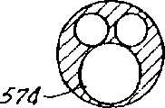
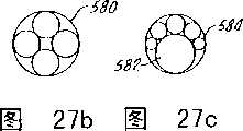
图27A-D显示了多腔套管560的多种结构。在图27A中,显示了一个带有较大高压腔574的三腔实心构体。图27B说明了一个带有外套管580的四腔实施例,使得流体可以在套管和其中四个管道外表面之间通过。图27C与图27B中的四腔套管类似,但包括一个大腔582和多个较小腔584。最后,图27D图解了一个带有一个大容量高压主腔586和多个较小腔588的腔组合,较小腔围绕圆周以均匀的排列附着。27A-D illustrate various configurations of a multi-lumen cannula 560 . In Figure 27A, a three-lumen solid body with a larger high-
图28和29说明了另一个多腔套管590的实施例,带有一个高压主套管592和多个外管或辅助管道594。28 and 29 illustrate another embodiment of a
在此描述了本发明的示范实施例,但本领域的普通技术人员应该理解:这儿的公开只是示范性的,在本发明的范围内可以作出多种其他变换、改变和修改。因此,本发明不限于这儿阐述的特定实施例。Exemplary embodiments of the present invention are described herein, but those skilled in the art should understand that the disclosure here is only exemplary, and various other changes, changes and modifications can be made within the scope of the present invention. Accordingly, the invention is not limited to the particular embodiments set forth herein.
Claims (24)
Applications Claiming Priority (4)
| Application Number | Priority Date | Filing Date | Title |
|---|---|---|---|
| US75676396A | 1996-11-26 | 1996-11-26 | |
| US08/756,763 | 1996-11-26 | ||
| US95310597A | 1997-10-17 | 1997-10-17 | |
| US08/953,105 | 1997-10-17 |
Related Child Applications (1)
| Application Number | Title | Priority Date | Filing Date |
|---|---|---|---|
| CNB2004100068513ADivisionCN100400121C (en) | 1996-11-26 | 1997-11-21 | Multiple lumen access device |
Publications (2)
| Publication Number | Publication Date |
|---|---|
| CN1238705Atrue CN1238705A (en) | 1999-12-15 |
| CN1161162C CN1161162C (en) | 2004-08-11 |
Family
ID=27116290
Family Applications (2)
| Application Number | Title | Priority Date | Filing Date |
|---|---|---|---|
| CNB971801037AExpired - LifetimeCN1161162C (en) | 1996-11-26 | 1997-11-21 | Multi-lumen access device |
| CNB2004100068513AExpired - LifetimeCN100400121C (en) | 1996-11-26 | 1997-11-21 | Multiple lumen access device |
Family Applications After (1)
| Application Number | Title | Priority Date | Filing Date |
|---|---|---|---|
| CNB2004100068513AExpired - LifetimeCN100400121C (en) | 1996-11-26 | 1997-11-21 | Multiple lumen access device |
Country Status (14)
| Country | Link |
|---|---|
| EP (2) | EP0956072B1 (en) |
| JP (3) | JP3761586B2 (en) |
| KR (1) | KR100480402B1 (en) |
| CN (2) | CN1161162C (en) |
| AT (2) | ATE206942T1 (en) |
| AU (1) | AU717833B2 (en) |
| BR (1) | BR9713985A (en) |
| CA (2) | CA2409240C (en) |
| CZ (1) | CZ290023B6 (en) |
| DE (2) | DE69732864T2 (en) |
| ES (2) | ES2240354T3 (en) |
| IL (1) | IL129693A (en) |
| RU (1) | RU2197285C2 (en) |
| WO (1) | WO1998024501A1 (en) |
Cited By (7)
| Publication number | Priority date | Publication date | Assignee | Title |
|---|---|---|---|---|
| CN102258389A (en)* | 2011-05-18 | 2011-11-30 | 中国人民解放军第三军医大学第二附属医院 | Aspiration biopsy sheath |
| CN101400401B (en)* | 2006-03-13 | 2012-11-07 | 瑞尼斯豪(爱尔兰)有限公司 | A fluid connector for fluid delivery apparatus |
| CN104840226A (en)* | 2015-05-29 | 2015-08-19 | 杨雪鹰 | Incision retracting fixator applicable to single-pore thoracoscopic surgery |
| CN105011892A (en)* | 2015-06-30 | 2015-11-04 | 中国人民解放军成都军区总医院 | Multiple-pipe capsule endoscope |
| CN106943164A (en)* | 2006-12-01 | 2017-07-14 | 波士顿科学股份有限公司 | Direct drive endoscopy systems and method |
| CN107485427A (en)* | 2017-09-21 | 2017-12-19 | 金国鑫 | A kind of assistive device of total surgical resection |
| CN114344668A (en)* | 2020-09-29 | 2022-04-15 | 巴德阿克塞斯系统股份有限公司 | Multi-lumen catheter and catheter system |
Families Citing this family (43)
| Publication number | Priority date | Publication date | Assignee | Title |
|---|---|---|---|---|
| US6827710B1 (en) | 1996-11-26 | 2004-12-07 | Edwards Lifesciences Corporation | Multiple lumen access device |
| US6013068A (en)* | 1998-07-28 | 2000-01-11 | Spiegelhalter; Judith A. | Variable lumen catheter |
| US6234958B1 (en) | 1998-11-30 | 2001-05-22 | Medical Access Systems, Llc | Medical device introduction system including medical introducer having a plurality of access ports and methods of performing medical procedures with same |
| US6328730B1 (en)* | 1999-03-26 | 2001-12-11 | William W. Harkrider, Jr. | Endoluminal multi-luminal surgical sheath and method |
| AU2004201028B2 (en)* | 1999-06-08 | 2006-05-18 | Edwards Lifesciences Corporation | Multiple lumen access device |
| MXPA01012633A (en)* | 1999-06-08 | 2002-06-21 | Edwards Lifesciences Corp | Multiple lumen access device. |
| US6592544B1 (en)* | 1999-11-24 | 2003-07-15 | Edwards Lifesciences Corporation | Vascular access devices having hemostatic safety valve |
| US8323228B2 (en) | 2007-04-12 | 2012-12-04 | Rex Medical L.P. | Dialysis catheter |
| US20020095203A1 (en)* | 2001-01-18 | 2002-07-18 | Intra Therapeutics, Inc. | Catheter system with spacer member |
| US6623491B2 (en)* | 2001-01-18 | 2003-09-23 | Ev3 Peripheral, Inc. | Stent delivery system with spacer member |
| US7044441B2 (en)* | 2001-08-10 | 2006-05-16 | Cardinal Health 303, Inc. | Valved male luer connector having sequential valve timing |
| US7112177B2 (en)* | 2003-03-04 | 2006-09-26 | Wolfe Tory Medical, Inc. | Apparatus for monitoring intra-abdominal pressure |
| JP2006263247A (en)* | 2005-03-25 | 2006-10-05 | Sumitomo Bakelite Co Ltd | Medical catheter, metal mold, and manufacturing method for medical catheter |
| US8394015B2 (en) | 2006-01-05 | 2013-03-12 | Children's Medical Center Corporation | Instrument port for minimally invasive cardiac surgery |
| CN101421000B (en)* | 2006-03-20 | 2013-01-30 | 麦德托尼克公司 | Breakable or removable valves and instruments |
| GB0614452D0 (en)* | 2006-07-20 | 2006-08-30 | Young Peter J | Connector system |
| US8070189B2 (en)* | 2007-06-20 | 2011-12-06 | Carefusion 303, Inc. | Safety luer connection |
| GB2445437B (en)* | 2007-07-06 | 2008-11-26 | Applied Medical Technology Ltd | Cannula insertion device |
| US9687333B2 (en) | 2007-08-31 | 2017-06-27 | BiO2 Medical, Inc. | Reduced profile central venous access catheter with vena cava filter and method |
| FR2927541B1 (en)* | 2008-02-15 | 2023-03-03 | Vygon | SIMPLIFICATION AND IMPROVEMENT OF MULTILUMERA CENTRAL VENOUS CATHETERS. |
| ES2683894T3 (en) | 2008-03-26 | 2018-09-28 | Medical Components, Inc. | Triple light catheter |
| JP5965147B2 (en) | 2008-05-26 | 2016-08-03 | ノバルティス アーゲー | Kit for topical application of drugs |
| US8888758B2 (en)* | 2008-09-05 | 2014-11-18 | Carefusion 303, Inc. | Closed male luer device for minimizing leakage during connection and disconnection |
| EP2174602B1 (en)* | 2008-10-07 | 2012-09-19 | Neurendo B.V. | A minimal invasive neurosurgery assembly |
| WO2010085865A1 (en)* | 2009-01-28 | 2010-08-05 | Gusmao Marcos De Oliveira | Device for fastening metallic guides and balloon catheters for carrying out medical procedures involving percutaneous vascular surgery |
| US8734458B2 (en)* | 2009-12-07 | 2014-05-27 | Globus Medical, Inc. | Methods and apparatus for treating vertebral fractures |
| US20110251465A1 (en)* | 2010-04-12 | 2011-10-13 | Tyco Healthcare Group Lp | Hollow multi-lumen access port |
| US8591450B2 (en) | 2010-06-07 | 2013-11-26 | Rex Medical L.P. | Dialysis catheter |
| JP5817181B2 (en)* | 2011-03-31 | 2015-11-18 | 住友ベークライト株式会社 | Medical equipment |
| US8721588B2 (en)* | 2011-04-15 | 2014-05-13 | DePuy Synthes Products, LLC | Noncircular inner lumen guiding catheter with assisted variable support |
| EP2964307A4 (en)* | 2013-03-05 | 2016-12-21 | Bio2 Medical Inc | Reduced profile central venous access catheter with vena cava filter and method |
| PL2997992T3 (en)* | 2013-05-13 | 2022-03-21 | Inside Medical Indústria E Comércio De Produtos Médicos Hospitalares Ltda - Me | Mechanism for guiding and/or releasing an endoprosthesis at a blood vessel lesion region, used in a medical device of the type of a cathether |
| DE102015217061A1 (en)* | 2015-09-07 | 2017-03-09 | Raumedic Ag | tube |
| CN106913373A (en)* | 2015-12-28 | 2017-07-04 | 中国科学院沈阳自动化研究所 | A kind of special-shaped balloon instrument repaired for endometrium |
| US11547276B2 (en) | 2018-03-09 | 2023-01-10 | The Children's Medical Center Corporation | Optical bulb for surgical instrument port |
| US11213316B2 (en) | 2018-03-09 | 2022-01-04 | The Children's Medical Center Corporation | Gasket with multi-leaflet valve for surgical port apparatus |
| US11324555B2 (en) | 2018-03-09 | 2022-05-10 | The Children's Medical Center Corporation | Instrument port including optical bulb secured to port body |
| US11284788B2 (en) | 2018-03-09 | 2022-03-29 | The Children's Medical Center Corporation | Instrument port with fluid flush system |
| EP3883631A1 (en)* | 2018-11-25 | 2021-09-29 | Patient Shield Concepts, LLC | Catheter for fluid drainage and medication delivery from/to a patient |
| CN114641334A (en)* | 2019-09-30 | 2022-06-17 | 阿比奥梅德公司 | Malleable sheath body |
| WO2023202465A1 (en)* | 2022-04-21 | 2023-10-26 | 微创优通医疗科技(上海)有限公司 | Medical catheter, device and system |
| WO2024006482A2 (en)* | 2022-06-30 | 2024-01-04 | Inari Medical, Inc. | Apparatuses, methods and systems for the percutaneous treatment of cholelithiasis |
| WO2024123449A1 (en)* | 2022-12-06 | 2024-06-13 | Boston Scientific Scimed Inc. | Tri-tube repositioning sheath |
Family Cites Families (13)
| Publication number | Priority date | Publication date | Assignee | Title |
|---|---|---|---|---|
| SU1391626A1 (en)* | 1986-10-23 | 1988-04-30 | Институт сердечно-сосудистой хирургии им.А.Н.Бакулева | Arrangement for inserting surgical instrument |
| US5021044A (en)* | 1989-01-30 | 1991-06-04 | Advanced Cardiovascular Systems, Inc. | Catheter for even distribution of therapeutic fluids |
| JPH03136668A (en)* | 1989-10-24 | 1991-06-11 | Olympus Optical Co Ltd | Internally inserting medical apparatus |
| ATE112471T1 (en)* | 1990-02-16 | 1994-10-15 | Jean Amiel | PROBE WITH MULTIPLE CHANNEL. |
| DE4037641C2 (en) | 1990-11-27 | 1995-06-14 | Haindl Hans | catheter |
| US5167623A (en)* | 1990-12-27 | 1992-12-01 | The Kendall Company | Multilumen catheter |
| US5156596A (en)* | 1991-02-04 | 1992-10-20 | Menlo Care, Inc. | Catheter with changeable number of lumens |
| CA2038676C (en)* | 1991-03-20 | 1995-12-26 | Geoffrey S. Martin | Infusion catheter |
| US5215527A (en)* | 1991-12-12 | 1993-06-01 | Becton, Dickinson And Company | Catheter introducer assembly |
| JPH0663004A (en)* | 1992-01-14 | 1994-03-08 | Olympus Optical Co Ltd | Tube for medical treatment |
| US5250038A (en)* | 1992-10-09 | 1993-10-05 | Cook Incorporated | Multiple lumen vascular access introducer sheath |
| ATE141481T1 (en)* | 1993-06-16 | 1996-09-15 | White Spot Ag | DEVICE FOR INTRODUCING FIBRIN GLUE INTO A STITCH CHANNEL |
| US5472418A (en) | 1994-07-28 | 1995-12-05 | Palestrant; Aubrey M. | Flattened collapsible vascular catheter |
- 1997
- 1997-11-20CACA002409240Apatent/CA2409240C/ennot_activeExpired - Lifetime
- 1997-11-20CACA002272691Apatent/CA2272691C/ennot_activeExpired - Fee Related
- 1997-11-20KRKR10-1999-7004629Apatent/KR100480402B1/ennot_activeExpired - Fee Related
- 1997-11-21WOPCT/US1997/021253patent/WO1998024501A1/enactiveIP Right Grant
- 1997-11-21JPJP52561798Apatent/JP3761586B2/ennot_activeExpired - Fee Related
- 1997-11-21EPEP97949506Apatent/EP0956072B1/ennot_activeExpired - Lifetime
- 1997-11-21CNCNB971801037Apatent/CN1161162C/ennot_activeExpired - Lifetime
- 1997-11-21RURU99113434/14Apatent/RU2197285C2/ennot_activeIP Right Cessation
- 1997-11-21ILIL12969397Apatent/IL129693A/ennot_activeIP Right Cessation
- 1997-11-21CNCNB2004100068513Apatent/CN100400121C/ennot_activeExpired - Lifetime
- 1997-11-21AUAU76231/98Apatent/AU717833B2/ennot_activeCeased
- 1997-11-21DEDE69732864Tpatent/DE69732864T2/ennot_activeExpired - Lifetime
- 1997-11-21CZCZ19991821Apatent/CZ290023B6/ennot_activeIP Right Cessation
- 1997-11-21EPEP01301050Apatent/EP1121954B1/ennot_activeExpired - Lifetime
- 1997-11-21BRBR9713985-8Apatent/BR9713985A/ennot_activeIP Right Cessation
- 1997-11-21ESES01301050Tpatent/ES2240354T3/ennot_activeExpired - Lifetime
- 1997-11-21DEDE69707505Tpatent/DE69707505T2/ennot_activeExpired - Lifetime
- 1997-11-21ESES97949506Tpatent/ES2166104T3/ennot_activeExpired - Lifetime
- 1997-11-21ATAT97949506Tpatent/ATE206942T1/ennot_activeIP Right Cessation
- 1997-11-21ATAT01301050Tpatent/ATE291457T1/ennot_activeIP Right Cessation
- 2005
- 2005-11-01JPJP2005318887Apatent/JP3944222B2/ennot_activeExpired - Lifetime
- 2007
- 2007-02-09JPJP2007031339Apatent/JP2007152137A/ennot_activeWithdrawn
Cited By (10)
| Publication number | Priority date | Publication date | Assignee | Title |
|---|---|---|---|---|
| CN101400401B (en)* | 2006-03-13 | 2012-11-07 | 瑞尼斯豪(爱尔兰)有限公司 | A fluid connector for fluid delivery apparatus |
| CN106943164A (en)* | 2006-12-01 | 2017-07-14 | 波士顿科学股份有限公司 | Direct drive endoscopy systems and method |
| CN106943164B (en)* | 2006-12-01 | 2021-11-19 | 波士顿科学股份有限公司 | Direct drive endoscope system and method |
| US11712150B2 (en) | 2006-12-01 | 2023-08-01 | Boston Scientific Scimed, Inc. | Medical systems comprising tool members |
| CN102258389A (en)* | 2011-05-18 | 2011-11-30 | 中国人民解放军第三军医大学第二附属医院 | Aspiration biopsy sheath |
| CN102258389B (en)* | 2011-05-18 | 2013-04-03 | 中国人民解放军第三军医大学第二附属医院 | Aspiration biopsy sheath |
| CN104840226A (en)* | 2015-05-29 | 2015-08-19 | 杨雪鹰 | Incision retracting fixator applicable to single-pore thoracoscopic surgery |
| CN105011892A (en)* | 2015-06-30 | 2015-11-04 | 中国人民解放军成都军区总医院 | Multiple-pipe capsule endoscope |
| CN107485427A (en)* | 2017-09-21 | 2017-12-19 | 金国鑫 | A kind of assistive device of total surgical resection |
| CN114344668A (en)* | 2020-09-29 | 2022-04-15 | 巴德阿克塞斯系统股份有限公司 | Multi-lumen catheter and catheter system |
Also Published As
| Publication number | Publication date |
|---|---|
| JP2001506879A (en) | 2001-05-29 |
| CN100400121C (en) | 2008-07-09 |
| WO1998024501A1 (en) | 1998-06-11 |
| CA2272691C (en) | 2003-09-09 |
| CN1557510A (en) | 2004-12-29 |
| ATE291457T1 (en) | 2005-04-15 |
| EP1121954B1 (en) | 2005-03-23 |
| JP2006051406A (en) | 2006-02-23 |
| EP0956072A1 (en) | 1999-11-17 |
| EP0956072B1 (en) | 2001-10-17 |
| CN1161162C (en) | 2004-08-11 |
| ATE206942T1 (en) | 2001-11-15 |
| DE69707505D1 (en) | 2001-11-22 |
| DE69707505T2 (en) | 2002-06-13 |
| CA2272691A1 (en) | 1998-06-11 |
| AU717833B2 (en) | 2000-04-06 |
| KR100480402B1 (en) | 2005-04-06 |
| IL129693A (en) | 2004-09-27 |
| ES2240354T3 (en) | 2005-10-16 |
| DE69732864T2 (en) | 2006-04-13 |
| DE69732864D1 (en) | 2005-04-28 |
| ES2166104T3 (en) | 2002-04-01 |
| CZ9901821A3 (en) | 2001-03-14 |
| CA2409240A1 (en) | 1998-06-11 |
| CA2409240C (en) | 2007-08-21 |
| IL129693A0 (en) | 2000-02-29 |
| JP2007152137A (en) | 2007-06-21 |
| JP3761586B2 (en) | 2006-03-29 |
| CZ290023B6 (en) | 2002-05-15 |
| KR20000057249A (en) | 2000-09-15 |
| AU7623198A (en) | 1998-06-29 |
| BR9713985A (en) | 2000-02-08 |
| RU2197285C2 (en) | 2003-01-27 |
| EP1121954A1 (en) | 2001-08-08 |
| JP3944222B2 (en) | 2007-07-11 |
Similar Documents
| Publication | Publication Date | Title |
|---|---|---|
| CN1238705A (en) | multi-lumen channel device | |
| EP1712248B1 (en) | Multiple lumen access device | |
| US6827710B1 (en) | Multiple lumen access device | |
| US20050080398A1 (en) | Co-axial tapered catheter | |
| AU2004201028B2 (en) | Multiple lumen access device | |
| AU738086B2 (en) | Multiple lumen access device | |
| MXPA99004659A (en) | Multiple lumen access device | |
| HUP9903396A2 (en) | Multi-channel access creation device |
Legal Events
| Date | Code | Title | Description |
|---|---|---|---|
| C06 | Publication | ||
| PB01 | Publication | ||
| C10 | Entry into substantive examination | ||
| SE01 | Entry into force of request for substantive examination | ||
| C53 | Correction of patent of invention or patent application | ||
| COR | Change of bibliographic data | Free format text:CORRECT: APPLICANT; FROM: BAXTER INTERNATIONAL LTD. TO: EDWARDS LIFE SCIENCES, INC. | |
| CP03 | Change of name, title or address | Address after:American California Applicant after:Edwards Lift Science Inc. Address before:Illinois State Applicant before:Baxter International Inc. | |
| C14 | Grant of patent or utility model | ||
| GR01 | Patent grant | ||
| CX01 | Expiry of patent term | Granted publication date:20040811 |