CN1237062A - digital camera capable of image processing - Google Patents
digital camera capable of image processingDownload PDFInfo
- Publication number
- CN1237062A CN1237062ACN99105822ACN99105822ACN1237062ACN 1237062 ACN1237062 ACN 1237062ACN 99105822 ACN99105822 ACN 99105822ACN 99105822 ACN99105822 ACN 99105822ACN 1237062 ACN1237062 ACN 1237062A
- Authority
- CN
- China
- Prior art keywords
- image
- frame
- digital camera
- monitor
- animation frame
- Prior art date
- Legal status (The legal status is an assumption and is not a legal conclusion. Google has not performed a legal analysis and makes no representation as to the accuracy of the status listed.)
- Granted
Links
Images


Classifications
- H—ELECTRICITY
- H04—ELECTRIC COMMUNICATION TECHNIQUE
- H04N—PICTORIAL COMMUNICATION, e.g. TELEVISION
- H04N5/00—Details of television systems
- H04N5/222—Studio circuitry; Studio devices; Studio equipment
- H04N5/262—Studio circuits, e.g. for mixing, switching-over, change of character of image, other special effects ; Cameras specially adapted for the electronic generation of special effects
- H04N5/2621—Cameras specially adapted for the electronic generation of special effects during image pickup, e.g. digital cameras, camcorders, video cameras having integrated special effects capability
- H—ELECTRICITY
- H04—ELECTRIC COMMUNICATION TECHNIQUE
- H04N—PICTORIAL COMMUNICATION, e.g. TELEVISION
- H04N5/00—Details of television systems
- H04N5/222—Studio circuitry; Studio devices; Studio equipment
- H04N5/262—Studio circuits, e.g. for mixing, switching-over, change of character of image, other special effects ; Cameras specially adapted for the electronic generation of special effects
- H—ELECTRICITY
- H04—ELECTRIC COMMUNICATION TECHNIQUE
- H04N—PICTORIAL COMMUNICATION, e.g. TELEVISION
- H04N23/00—Cameras or camera modules comprising electronic image sensors; Control thereof
- H04N23/60—Control of cameras or camera modules
- H04N23/63—Control of cameras or camera modules by using electronic viewfinders
- H04N23/631—Graphical user interfaces [GUI] specially adapted for controlling image capture or setting capture parameters
- H04N23/632—Graphical user interfaces [GUI] specially adapted for controlling image capture or setting capture parameters for displaying or modifying preview images prior to image capturing, e.g. variety of image resolutions or capturing parameters
- H—ELECTRICITY
- H04—ELECTRIC COMMUNICATION TECHNIQUE
- H04N—PICTORIAL COMMUNICATION, e.g. TELEVISION
- H04N5/00—Details of television systems
- H04N5/222—Studio circuitry; Studio devices; Studio equipment
- H04N5/262—Studio circuits, e.g. for mixing, switching-over, change of character of image, other special effects ; Cameras specially adapted for the electronic generation of special effects
- H04N5/2628—Alteration of picture size, shape, position or orientation, e.g. zooming, rotation, rolling, perspective, translation
- H—ELECTRICITY
- H04—ELECTRIC COMMUNICATION TECHNIQUE
- H04N—PICTORIAL COMMUNICATION, e.g. TELEVISION
- H04N5/00—Details of television systems
- H04N5/222—Studio circuitry; Studio devices; Studio equipment
- H04N5/262—Studio circuits, e.g. for mixing, switching-over, change of character of image, other special effects ; Cameras specially adapted for the electronic generation of special effects
- H04N5/272—Means for inserting a foreground image in a background image, i.e. inlay, outlay
Landscapes
- Engineering & Computer Science (AREA)
- Multimedia (AREA)
- Signal Processing (AREA)
- Human Computer Interaction (AREA)
- Studio Devices (AREA)
- Television Signal Processing For Recording (AREA)
Abstract
Description
Translated fromChinese本发明是关于数字摄象机,特别是关于将例如所摄取的运动图象或再现的静止图象显示在监视器上的数字摄象机。The present invention relates to a digital video camera, and more particularly to a digital video camera for displaying, for example, captured moving images or reproduced still images on a monitor.
历来的这种数字摄象机是将记录在记录媒体上的图象再现于内装的监视器上。Conventional digital cameras of this type reproduce images recorded on recording media on built-in monitors.
但历来的技术只能单一地再现记录图象,而在对记录的图象进行加工时则需另外准备图象处理装置。However, the conventional technology can only reproduce the recorded image only, and an image processing device needs to be prepared separately when the recorded image is processed.
因此,本发明的主要目的就是提供无需另外准备图象处理装置而能处理图象的数字摄象机。Accordingly, a main object of the present invention is to provide a digital video camera capable of processing images without preparing an additional image processing device.
本发明的一个方面是,设置有对被摄对象摄影的摄影单元,响应操作者的动画帧形成指示在监视器上形成小于监视器帧的动画帧的第一形成单元,和在动画帧内显示由摄影单元摄影得到的被摄对象的动画象的动画象显示单元。这样,由于动画象按照操作者的帧形成指示显示在监视器上形成的所希望的帧内,所以无需准备图象处理装置就能得到经过处理的图象。One aspect of the present invention is provided with a photographing unit for photographing a subject, a first forming unit for forming an animation frame smaller than a monitor frame on a monitor in response to an animation frame formation instruction of an operator, and displaying in the animation frame An animation image display unit for an animation image of the subject captured by the imaging unit. In this way, since the moving image is displayed in the desired frame formed on the monitor according to the frame formation instruction of the operator, the processed image can be obtained without preparing an image processing device.
本发明的另一个方面是,在由记录媒体再现相当于监视器帧的第一静止图象于监视器上显示的数字摄象机中,设置有按照操作者的合成指示由记录媒体再现小于监视器帧的第二静止图象的第二静止图象再现单元,和将第二静止图象合成到第一静止图象的合成单元。从而,由于按照操作者的合成指示将小于监视器帧的第二静止图象合成到第一静止图象,所以即使不准备图象处理装置能得到经处理的图象。Another aspect of the present invention is that, in a digital video camera for reproducing a first still image corresponding to a monitor frame from a recording medium and displaying it on a monitor, a device is provided to reproduce a still image smaller than the monitor frame from the recording medium according to an operator's composite instruction. A second still image reproducing unit for the second still image of the frame, and a synthesizing unit for synthesizing the second still image to the first still image. Therefore, since the second still image smaller than the monitor frame is composited with the first still image according to the composite instruction of the operator, a processed image can be obtained even if no image processing means is prepared.
在本发明的再一个方面是,设置有设定在连贯图象显示区间显示一部分再现图象的设定单元,在所设定区间作连贯图象显示来生成合成图象的图象合成单元,和记录所生成的合成图象的记录单元。这样,就能得到能在单个数字摄象机上很容易地合成再现图象与连贯图象、即使不准备以图象处理装置也能得到经处理过的图象。In yet another aspect of the present invention, a setting unit for displaying a part of the reproduced image in a continuous image display interval is provided, and an image synthesis unit for generating a composite image by performing continuous image display in the set interval, and a recording unit for recording the generated composite image. Thus, a reproduced image and a coherent image can be easily synthesized on a single digital camera, and a processed image can be obtained even without an image processing device.
对附图的简要说明:A brief description of the attached drawings:
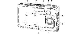
图1A和1B为表示按照本发明实施例1的数字摄象机的外观结构的斜视图;1A and 1B are oblique views showing the appearance structure of a digital camera according to Embodiment 1 of the present invention;
图2为表示图1A和1B中所示数字摄象机内装图象记录再现电路的结构的方框图;Fig. 2 is a block diagram showing the structure of the built-in image recording and reproducing circuit of the digital camera shown in Figs. 1A and 1B;
图3A和3B说明图1A和1B中所示数字摄象机的摄影模式;3A and 3B illustrate shooting modes of the digital video camera shown in FIGS. 1A and 1B;
图4A和4B说明图1A和1B所示数字摄象机的再现模式;4A and 4B illustrate reproduction modes of the digital video camera shown in FIGS. 1A and 1B;
图5A~5D说明图1A和1B中所示数字摄象机的图象合成功能;5A-5D illustrate the image synthesis function of the digital video camera shown in FIGS. 1A and 1B;
图6A~6F表示实施例1的变型例;Fig. 6A~6F represent the modification example of embodiment 1;
图7为表示本发明实施例2数字摄象机内装图象记录再现电路的结构的方框图;Fig. 7 is a block diagram showing the structure of the digital camera built-in image recording and reproducing circuit according to Embodiment 2 of the present invention;
图8为表示图7中所示变焦电路的构成的方框图;Fig. 8 is a block diagram showing the configuration of the zoom circuit shown in Fig. 7;
图9为表示图7中所示存储器控制电路的构成的方框图;FIG. 9 is a block diagram showing the configuration of the memory control circuit shown in FIG. 7;
图10为表示图9中所地址运算单元的结构的方框图;Fig. 10 is a block diagram representing the structure of the address arithmetic unit in Fig. 9;
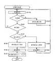
图11为表示摄象模式中一部分操作的流程图;Fig. 11 is a flow chart showing a part of the operation in the camera mode;
图12为表示摄象模式中另一部分操作的流程图;Fig. 12 is a flow chart showing another part of the operation in the camera mode;
图13为表示摄象模式中再一部分操作的流程图;Fig. 13 is a flow chart showing still another part of the operation in the camera mode;
图14为表示再现模式中一部分操作的流程图:Fig. 14 is a flowchart showing a part of the operation in the playback mode:
图15为表示再现模式中另一部分操作的流程图;Fig. 15 is a flow chart showing another part of the operation in the reproduction mode;
图16为表示再现模式中再一部分操作的流程图;Fig. 16 is a flowchart showing still another part of the operation in the reproduction mode;
图17为表示再现模式中又一部分操作的流程图;Fig. 17 is a flowchart showing still another part of the operation in the reproduction mode;
图18为表示再现模式中还有一部分操作的流程图;Fig. 18 is a flowchart showing a part of the operation in the playback mode;
图19为表示动画缩小模式中一部分操作的流程图;Fig. 19 is a flow chart showing a part of the operation in the animation zoom-out mode;
图20A~20F表示动画缩小模式操作示例的示意图:20A to 20F are schematic diagrams showing examples of operation in the animation zoom-out mode:
图21A~21F为表示动画缩小模式中操作的另一例的示意图;21A to 21F are schematic diagrams showing another example of operations in the animation zoom-out mode;
图22A~22E为表示静止画面截取模式中操作的示例的示意图;和22A to 22E are diagrams showing examples of operations in the still picture capture mode; and
图23A~23D为表示静止画面粘接模式中操作的示例图解。23A to 23D are illustrations showing examples of operations in the still picture splicing mode.
图1A为表示按照本发明实施例1的数字摄象机外观结构的由正面侧(镜头侧)看的斜视图,图1B为由背面侧看的斜视图。1A is a perspective view from the front side (lens side) showing the appearance structure of a digital camera according to Embodiment 1 of the present invention, and FIG. 1B is a perspective view from the rear side.
参看图1A和1B,在此数字摄象机的正面侧设置有镜头1,与电源开关连动的镜头盖2,光学取景器3,闪光器4,设置有自动定时用LED5的其上面和侧面上的快门按钮6,3点式主开关7,宏切换手柄8和定时器9。而在此数字摄象机的背面设置有LCD10,模式按钮11设定按钮12,方向指示钮13和麦克风14。Referring to Fig. 1A and 1B, lens 1 is arranged on the front side of this digital video camera, the lens cover 2 linked with power switch,
主开关7用于在接通LCD10的摄影模式、断开LCD10的摄影模式、和再现模式的三种模式的切换。在接通LCD10的摄影模式中,在LCD10上显示上显示连贯图象,该连贯图象被加以记录。在断开LCD10的摄影模式中,与通常的银盐式摄象机同样利用光学取景器进行摄景。在再现模式中,LCD10接通,在LCD10上显示再现图象。在CDC10上除连贯图象和再现图象还显示表明记录条件、再现功能的种种图标标记(字符)。The
依靠用手指轻按方向指示按钮13的各个四角的左方向指示部分13a、右方向指示部分13b、上方向指示部分13c和下方向指示部分13d就可能进行再现图象的馈送/返回、记录条件的设定、再现功能的选择等。By lightly pressing the left
图2为表示此数字摄象机中内装的图象记录再现电路20的结构的电路方框图。FIG. 2 is a circuit block diagram showing the structure of an image recording and reproducing
参看图2,在此图象记录再现电路20中,系统控制器41响应来自镜头盖2、快门按钮6、主开关7、宏切换手柄8、模式按钮11、设定按钮12和方向指示按钮13的信号,在规定的定时时刻给予CPU42各种控制信号。CPU42根据由系统控制器41输出的控制信号控制存储器控电路27和瞬间存储器控制电路47。Referring to Fig. 2, in this image recording and reproducing
存储器控制电路27控制第一信号处理电路24、第二信号处理电路29、JPEG电路44、缓存器25、28、43和SDRAM26。SDRAM26的图象数据的写入/读出通过缓存器25、28、43进行。缓存器25、28、43与SDRAM26的传送速度(写入/读出速度)高于缓存器25、28、43与第一信号处理电路24、第二信号处理电路和JPEG电路44的数据传送速度,这样就可能使这些电路24、29、44几乎同时动作。The
而存储器控制电路27依靠控制字符发生器30和开关31以字符图象数据替换图象数据的一部分,在连贯图象和再现图象上写入字符图象。And the
瞬间存储器控制电路47控制缓存器45和瞬间存储器46,在通过缓存器45将在JPEG电路44中被压缩的图象数据写入到瞬间存储器46中的同时,通过缓存器45将由瞬间存储器46读出的数据输出到JPEG电路44。Instantaneous
在摄影模式时,由镜头1入射的光线通过未图示的互补式滤光器照射到CCD成象板21。CCD成象板21按照顺序扫描(象素依次扫描)输出各象素的电气信号(顺序扫描信号)。由CCD成象板21输出的顺序扫描信号被加给CDS/AGC电路22。In the photography mode, the incident light from the lens 1 is irradiated to the
CDS/AGC电路22对顺序扫描信号施加公知的去除噪声和电平调整经过这样处理的顺序扫描信号由A/D变换器23变换成数字数据(图象数据)。第一信号处理电路24对由A/D变换器23输出的图象数据进行公知的白均衡调整和伽玛补正,然后将此图象数据通过缓存器25加给SDRAM26。The CDS/
存储器控制电路27将图象数据写入SDRM26,然后将此图象数据以交错扫描读出。从而由SDRAM26交互地输出奇数组的半帧图象数据和偶数组的图象数据。由SDRAM26输出的图象数据通过缓存器28被输入到第二信号处理电路29,同时还通过缓存器43被输入到JPEG电路44。The
第二信号处理电路29对所输入的图象数据进行色插补等的处理,由第二信号处理电路29输出的图象数据通过开关31被加到D/A变换器32。D/A变换器32将图象数据变换成模拟信号(图象信号),通过输出端33输出此图象信号,同时加到LCD10。因此,如图3中所示那样,在LCD10上显示实时的运动图象(连贯图象)。The second
在此状态下如按模式按钮11,即如图3B中所示,在LCD10的端部显示出表示记录条件的各种图标51~59。在图3B中,虽然为使图面简洁各个图标以简单的空白四角形、加以斜线的四角形表示,而在实际上则为表示对应的记录条件的符号。图标51~59各自为用于进行静止画面摄影模式设定,高速连写模式设定,分辨率设定,声音记录设定,自动时间设定,宏模式设定,曝光校正设定,数字变焦设定。图标51~59的选择以方向指示按钮13进行。图标51~59中被选择的图标(在图中为51)以肯定状态(空白四角形)显示,除此以外的图标以否定状态(加有斜线的四角形)显示。在此状态下如按设定按钮12,以所选择的图标(这种情况为51)表示的条件(这种情况为静止图象摄影模式)即被设定。在设定记录条件后,如按模式按钮11,即消除图标51~59返回到图3A的状态。In this state, when the
操作者如按快门按钮6,PEG电路44即被激活,由SRAM26读出通过缓存器43输出到JPEG电路44的图象数据被按照JPEG格式压缩,此压缩数据通过缓存器45被写入瞬间存储器46。If the operator presses the
在再现模式时,由瞬间存储器46读出的压缩数据通过缓存器被输入到JPEG电路44。JPEG电路44将输入的压缩数据解压通过缓存器43加给SDRAM26。存储器控制电路27将图象数据写入SDRAM26,然后以交错扫描方式读出此图象数据。In the reproduction mode, the compressed data read from the
由SDRAM26读出的图象数据通过缓存器28、第二信号处理电路29、开关31被加到D/A变换器32,变换成模拟图象信号。此模拟图象信号被通过输出端33向外部输出,送往LCD10。因此如图4A中所示,在LCD10上显示再现图象60。在此状态下如按方向指示按钮13的左方向指示部分13a,即再现此再现图象之前所记录的图象;如按右方向指示部分13b,即再现此再现图象后记录的图象。从而就能选择再现所希望的图象。The image data read from
而在此状态下如按模式按钮11,即如图4B中所示,在LCD10的端部显示表示再现功能的各种图标61~68。图标61~68各自表示要进行再现模式选择,多重再现,再现平滑,保护,消除,图象合成,图表扫描,日期时刻设定。以方向指示按钮13选择图标61~68中的所希望的图标,如按设定按钮12以该图标表示的功能即被选定。不按设定按钮12而按模式按钮11即回图4A的状态。In this state, when the
下面对作为本申请的特征部分的图象合成功能加以说明。首先在图4A的状态利用方向指示按钮13进行再现图象的馈送/返回,选择成为背景的所希望的再现图象60。然后按模式按钮11如图4B中所示那样显示图标61~68,利用方向指示按钮13选择图象合成的图标66,按设定按钮12。Next, the image synthesis function which is a characteristic part of the present application will be described. First, in the state of FIG. 4A, the playback image is fed/returned using the
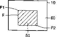
这样即选择了图象合成功能,如图5中所示,在再现图象60中显示垂直线L1和水平线L2。如按方向指示按钮13的左方向指示部分13a或右方向指示部分13b垂直线L1即向左方或右方移动,如按其上方向指示部分13c或下方向指示部分13d水平线L2即向上或向下移动。使垂直线L1和水平线L2移动来决定它们的交点第一点P1的位置。此第一点P1成为帧F的左上点。Thus, the image synthesis function is selected, and the vertical lineL1 and the horizontal lineL2 are displayed in the reproduced
在此状态下如按设定按钮12,如图5B中所示在第一点P1被确定的同时,还在再现图象60内显示垂直线L3和垂直线L4。如按方向指示按钮13的左方向指示部分13a或右方向指示部分13b垂直线L3向左或向右移动,如按其上方向指示部分13c或下方向指示部分13d水平线L4即向上或向下移动。垂直线L3和水平线L4可能分别在第一点P1的下侧和右侧移动。而如使垂直线L3和水平线L4的一方移动,为使以L1~L4作为四边的帧F的长宽比常行保持为3∶4,垂直线L3和水平线L4的另一方相随地移动。使垂直线L3和水平线L4移动来确定它们的交点第二点P2的位置。此第二点P2成为帧F的右下点。If the
在此状态下如按设定按钮12,如图5C中所示,即确定了帧F的大小和大致位置。如按方向指示按钮13的方向指示部分13a~13d,帧F即在指示的方向移动。移动帧F来确定帧位的位置。In this state, if the
在此状态下如按设定按钮12,如图5D中所示,在由帧F所包围的区域内显示连贯图象50。此时在图2的电路20中,由A/D变换器23生成的连贯图象数据按照帧F的大小和位置被第一信号处理电路24作读取处理及缩小平滑处理。被作中间抽取处理的连贯图象数据通过缓存器25被加到SDRAM26,被加在对应于写入到SDRAM26中的再现静止画面数据中的帧F所包围区域的部分。由于连贯图象为运动图象,加入的数据作顺序更新。这样,即在再现图象60内以所希望大小和位置开窗口在此窗口内显示连贯图象50。If the
在此状态下按压快门按钮,此时LCD10上显示中的合成图象的图象数据被JDEG电路44压缩,通过缓存器45被写入瞬间存储器46中。从而,合成图象就能与通常以摄影模式拍摄得的静止图象同样地再现。When the shutter button is pressed in this state, the image data of the synthesized image being displayed on the
在图5A~5D的状态下按压模式按钮11即返回到图5A的状态,再按模式按钮11返回图3B的状态。Press the
在此实施例中,虽然是将图象合成时作中间抽取处理的连贯图象数据加到再现图象数据上来生成合成图象的,但并不局限于此,也可以在将连贯图象数据全部和再现图象数据分别地写入SDRAM26的存储区域后,在帧F之外读出再现图象数据在帧F内读出连贯图象数据来生成合成图象。In this embodiment, although the continuous image data subjected to mid-decimation processing at the time of image synthesis is added to the reproduced image data to generate a synthesized image, it is not limited to this, and the continuous image data may also be After the entire and reproduced image data are separately written into the storage area of
在上述实施形态中,是使以L1~L4作四边的帧F的长宽比常行为3∶4那样来安置垂直线L3和水平线L4的。但也不局限于此,也可以使得能将第2点P2的位置不设定成3∶4的比例关系。In the above embodiment, the vertical lineL3 and the horizontal line L4 are arranged so that the aspect ratio of the frame F having four sidesL1 toL4 is always 3:4 . However, it is not limited thereto, and the position of the second pointP2 may not be set to a ratio of 3:4.
图6A~6F表示实施例1的变体。6A to 6F show variations of Example 1. FIG.
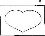
图6A为在LCD10上所显示的再现图象,图6B为连贯图象。在前述实施例中,确定帧F的位置后,按压设定按钮12时,如图6D中所示地显示在以帧F包围的区域内作内部抽取处理而缩小的连贯图象50。FIG. 6A is a reproduced image displayed on the
与其相反,在此变型例中,继续按设定按钮12时,即不象图6D中所示那样作中间抽取处理连贯图象而是如图6C中所示由全视野角出发显示仅在帧内选出的一部分的图象。On the contrary, in this modified example, when the
而在移动垂直线L1和水平线L2确定第一点P1的位置时,使垂直线L1和水平线L2的颜色由白变成为橙黄色,在移动垂直线L3和水平线L4帧F的长宽比成为3∶4时,将垂直线L3和水平线L4的颜色由例如图6E所示的双重线部的白色变成为图6F中所示的粗黑线部分的绿色亦可。When moving the vertical lineL1 and the horizontal lineL2 to determine the position of the first pointP1 , the color of the vertical lineL1 and the horizontal lineL2 is changed from white to orange-yellow, and when moving the vertical lineL3 and the horizontal lineL4 When the aspect ratio of the frame F becomes 3:4, the color of the vertical lineL3 and the horizontal lineL4 is changed from white in the double line part shown in FIG. 6E to green in the thick black line part shown in FIG. 6F also can.
第二实施例,在此实施例中,当设定动画缩小模式时,在监视器上显示点。此时操作员如操作光标键点即移动,如操作员在不同的二个点位置上操作确定键,即形成矩形的帧。即就是说,2个点位置成为帧的左上座际和右下座标。而后所摄取得的实时运动图象即在此矩形帧中被显示。所显示的运动图象被缩小到与此矩形帧和监视器帧的比例相应的倍率。在除去监视器帧内的此矩形帧之外的部分中也可以显示由记录媒体中再现的静止图象。这时如操作者操作快门按钮,监视器帧内的图象即被记录到记录媒体。Second embodiment, in this embodiment, when the animation zoom-out mode is set, dots are displayed on the monitor. At this time, if the operator operates the cursor key point, it will move, and if the operator operates the confirm key at two different positions, a rectangular frame will be formed. That is, the two point positions become the upper left coordinates and the lower right coordinates of the frame. Then the captured real-time moving image is displayed in this rectangular frame. The displayed moving picture is reduced to a magnification corresponding to the ratio of the rectangular frame to the monitor frame. A still image reproduced from a recording medium may also be displayed in a portion other than this rectangular frame within the monitor frame. At this time, when the operator operates the shutter button, the image within the monitor frame is recorded on the recording medium.
而在所再现的静止图象被显示在监视器上的状态下,设定静止图象粘贴模式时,另外记录的部分静止图象即被合成到当初所显示的静止图象上。这时如在上下方向操作光标键,部分静止图象即被转换,而如在左右方向上操作光标键,则转换部分图象下面所显示的静止图象。如快门钮被操作,所显示的合成图象即被记录到记录媒体。On the other hand, when the reproduced still image is displayed on the monitor, when the still image pasting mode is set, a part of the still image recorded separately is composited on the originally displayed still image. At this time, if the cursor key is operated in the up and down direction, the partial still image is switched, and if the cursor key is operated in the left and right direction, the still image displayed below the partial image is switched. If the shutter button is operated, the displayed composite image is recorded to the recording medium.
以下根据附图详细说明此实施例。This embodiment will be described in detail below with reference to the accompanying drawings.
参照图7,此实施例的数字摄象机70含有镜头71。被入射的摄影对象的光象通过镜头71照射到CCD成象板72。CCD成象板72在水平方向和垂直方向中具有640象素和480行大小的象素。Referring to FIG. 7, a
如模式设定开关87被设定到摄象一侧,系统控制器85即通过输入端83b将摄象机模式设定到CPU83。此时,CPU83对定时发生器84指示读出象素信号(摄象机信号),定时发生器84以光栅扫描方式由CCD成象板72读出摄象机信号。所读出的摄象机信号在A/D变换器73中被变换成数字信号(摄象机数据),经变换的摄象机数据被输入给信号处理电路74。在CCD成象板72的前面装有未图示的互补色滤光器,被输入的摄象机数据的各个的象素仅具有Ye、Cy、Mg和G中一个的互补色成分。因此,信号处理电路74对所输入的摄象机数据加以色分离处理,对由色分离得到的RGB数据施如YUV变换。If the
这样所得到的YUV数据亦即图象数据在经变焦电路75作规定的变焦处理之后,通过总线76输入到DRAM81,以光栅扫描方式被写入视频存储区81a。视频存储区81a具有相当于监视器80的帧(监视器帧)的容量,由变焦电路75输出的图象数据由DMA(直接存储器存取)被写入此视频存储区81a中。具体说,CPU83将写入请求与帧数据同时、亦即帧左上角上的X座标和Y座标以及帧的水平大小(X大小)和垂直大小(Y大小)的数据加到存储器控制电路78,存储器控制电路78根据此帧数据将图象数据写入视频存储区81a的规定位置。在通常的摄象机模式中,将监视器帧的帧数据输入存储器控制电路78。监视器帧的左上座标为(0,0),水平大小和垂直大小分别为640象素和480行,所以图象数据被全部写入视频存储区81a。The thus obtained YUV data, that is, image data, is subjected to predetermined zoom processing by the
视频存储区81a的图象数据在写入结束后,由存储器控制电路78以栅扫描方式读出,通过总线76加到视频编码器79。视频编码器79对输入的图象数据以NTSC方式编码,由此得到的合成图象信号被输出给兼作图象取景器的监视器80。由CCD成象板72摄取得的运动图象在整个监视器帧上显示。而在DRAM81的输入输出端口上设置有未图示的缓存器,由其改变图象数据的传送速率。因而图象数据的写入和读出并行执行。After the image data in the
在通常的摄象机模式中如操作者操作快门按钮89,CPU83即对定时发生器84指示中止电荷的读出。由此,不再由CCD成象板72读出新的图象数据,而在视频存贮区81a中继续保持快门按钮89被按压时刻的图象数据。CPU83由视频存储区81a以DMA方式读出图象数据,通过总线76输入给解压缩电路77。CPU83同时给予解压缩电路77以压缩指示。解压缩电路77对所输入的图象数据按JPEG方式加以压缩,压缩图象数据容纳进图象文件,然后将此图象文件加给存储器插件板82。而存储器插件板82上还被加有来自CPU83的写入指示,从而由解压缩电路77输出的图形文件即被记录到存储器插件板82。When the operator operates the
在操作者将模式开关87设定到再现侧时,系统控制器85将CPU83设定为再现模式。与之相应地CPU83由存储器插件板82再现所希望的图象文件,通过总线76加到解压缩电路77。在解压缩电路77中还加有来自CPU83的解压指示。解压缩电路77按JPEG方式解压所输入的图象文件的图象数据,将解压图象数据亦即再现图象数据输入给DRAM81。为将此再现图象数据写入视频存储区81a,由解压缩电路77对存储器制电路78提出写入请求,由CPU83对存储器控制电路78加给规定写入位置的帧数据。When the operator sets the
按照这样的写入请求和帧数据,存储器控制电路78将再现图象数据写入视频存储区81a。写入一完成,CPU83即将同样的帧数据和读出请求输入到存储器控制电路78,对应于这一点,存储器控制电路78由视频存储区81a读出再现图象数据。所读出的再现图象数据被加给视频编码器79,最后在监视器80上显示被再现的静止图象。In accordance with such a write request and frame data, the
变焦电路75如图8所示那样构成。由信号处理电路74输出的图象数据按象素时钟被写入到行存储器75a,此后按相同象素时钟延迟一行地读出。被读出的图象数据再写入另一行存储器75b,再延迟一行地被读出。从而由行存储器75a和75b同时输出连续的2行大小的图象数据。由行存储器75a输出的图象数据被直接输入到乘法器75g,同时由锁存电路75c作1象素延迟后被输入乘法器75f。而由行存储器75b输出的图象数据被直接输入给乘法器22i,同时由锁存电路75d作1象素延迟后输入到乘法器75h。The
在乘法器75g和75i中输入由加法器75y输出的数值数据的小数,在乘法器75f和75h中输入减法器75e由“1.0”中减去此小数得的补数。因此,被加到乘法器75g和75i的图象数据由小数加权,被加到乘法器75f和75h的图象数据由补数加权。乘法器75h和75g的输出由加法器75j相加,乘法器75h和75i的输出由加法器75k相加。依靠这样的乘法处理和加法处理就将水平变焦加到图象数据中。The decimals of the numerical data output from the adder 75y are input to the multipliers 75g and 75i, and the complements obtained by subtracting the decimals from "1.0" by the subtractor 75e are input to the multipliers 75f and 75h. Therefore, the image data supplied to the multipliers 75g and 75i is weighted by the decimal number, and the image data supplied to the multipliers 75f and 75h is weighted by the complement number. The outputs of the multipliers 75h and 75g are added by an adder 75j, and the outputs of the multipliers 75h and 75i are added by an adder 75k. By means of such multiplication processing and addition processing, horizontal zooming is added to the image data.
由加法器75j和75k输出的加法数据被输入给乘法器75n和75p。而由加法器75z输出的数值数据的小数被输入给乘法器75p,减法器75m由“1.0”减去此小数后的补数被输入到乘法器75n。从而,由加法器75k输出的加法数据被小数乘。乘法器75n和75p的输出然后由加法器75q相加,由此得到对水平和垂直方向任一方进行过平滑处理的图象数据。The added data output by the adders 75j and 75k are input to the multipliers 75n and 75p. The decimal number of the numerical data output from the adder 75z is input to the multiplier 75p, and the complement of the decimal number subtracted from "1.0" by the subtracter 75m is input to the multiplier 75n. Thus, the addition data output by the adder 75k is multiplied by a decimal. The outputs of the multipliers 75n and 75p are then added by an adder 75q, thereby obtaining image data smoothed in either of the horizontal and vertical directions.
由加法器75y和75z输出的数值数据如下述这样求取。CPU83将帧数据中所含的X大小数据和Y大小数据分别输入给H计数器75r和V计数器75s。由此,X大小成为H计数器75r的最大计数值,Y大小成为V计数器75s的最大计数值。H计数器75r被以“与”电路75x的输出增量在最大计数值输出进位信号然后由水平同步信号和垂直同步信号复位。另一方向,V计数器75s被由H计数器75r输出的进位信号增量,再由垂直同步信号复位。“与”电路75x的输出为分别构成被施加以变焦处理的图象的象数的定时的上升沿时钟,即变焦象素时钟。根据此变焦象数时钟H计数器75r和V计数器75s对变焦图象的水平象素数和垂直象素数进行计数。The numerical data output from the adders 75y and 75z are obtained as follows. The
除法器75t以由CPU83输出的水平变焦倍率除H计数器75r的计数值,除法器75u以CPU83所输的垂直变焦倍率除V计数器75s的计数值。除法器75t的除算结果由加法器75y与帧数据中所含的X座标数据相加,除法器75u的除算结果由加法器75z与帧数据中所含的Y座标数据相加。加法器75y和75z各自的加算结果表示当前由加法器75q输出的变焦象素对应于原图象的水平位置还是垂直位置。由加法器75y和75z输出这样的原图象的水平位置数据和垂直位置数据,水平位置数据的小数被输入到减法器75e、乘法器75g和75i,垂直位置数据的小数被输入到减法器75m和乘法器75p。The divider 75t divides the count value of the H counter 75r by the horizontal zoom factor output from the CPU83, and the divider 75u divides the count value of the V counter 75s by the vertical zoom factor input from the CPU83. The division result of the divider 75t is added to the X coordinate data contained in the frame data by the adder 75y, and the division result of the divider 75u is added to the Y coordinate data contained in the frame data by the adder 75z. The respective addition results of the adders 75y and 75z indicate whether the zoomed pixel currently output by the adder 75q corresponds to the horizontal position or the vertical position of the original image. The horizontal position data and vertical position data of such an original image are output by the adders 75y and 75z, the decimals of the horizontal position data are input to the subtractor 75e, the multipliers 75g and 75i, and the decimals of the vertical position data are input to the subtractor 75m and multiplier 75p.
由加法器75y和75z输出的水平位置和垂直位置数据的整数被输入给比较器75v和75w。并将计数原图象水平象素数得的水平计数值和计数原图象垂直象素数得的垂直计数值分别输入到比较器75v和75w。比较器75v和75w在所输入的二个数值一致时输出一致脉冲。“与”电路75x求取比较器75v和75w输出的一致脉冲的逻辑和,并将其作为变焦象素时钟输出。变焦象素时钟被输入到存储器控制电路78,存储器控制电路78仅将由加法器75q在与变焦象素时钟同时输出的象素数据写入DRAM81。据此,在DRAM81中就得到所希望的变焦倍率的图象数据。而作为原图象就成为入射在CCD成象板72上的被摄影对象的图象,而由信号处理电路74得到原图象数据。The integers of the horizontal position and vertical position data output by the adders 75y and 75z are input to the comparators 75v and 75w. And the horizontal count value obtained by counting the horizontal pixels of the original image and the vertical count value obtained by counting the vertical pixels of the original image are input to comparators 75v and 75w, respectively. The comparators 75v and 75w output a coincidence pulse when the two input values coincide. AND circuit 75x takes the logical sum of the coincident pulses output by comparators 75v and 75w, and outputs it as a zoom pixel clock. The zoom pixel clock is input to the
存储器控制电路78如图9中所示那样构成。帧数据中所含的X大小数和Y大小数据分别被装载到译码器93和94中,X座标数据和Y座标数据被装载到地址运算电路95。地址运算电路95如图10中所示构成,X座标数据和Y座标数据,详细说是被装载进寄存器105和106。在通常摄影机模式,译码器93和94各自保持有“640”和“480”的数值数据,寄存器105和106任一个均保持为“0”的数值数据。而寄存器105和106中保持的数值数据在垂直同步脉冲Vsync的输入定时更新。The
H计数器91根据由变焦电路75输入的变焦象素时钟增量,H计数器91的计数值(水平计数值)被输入到地址运算电路95和译码器93。译码器93对所输入的水平计数值与“640”进行比较,在两者一致时输出一致脉冲。H计数器91由此一致脉冲复位,V计数器92由此一致脉冲增量。而V计数器92的计数值(垂直计数值)被加给地址运算电路95和译码器94,译码器94在垂直计数值与“480”一致时将V计数器92复位。这样,H计数器91在计数到相当于帧的X大小的象数时被复位V计数器92在计数到相当于帧的Y大小的行时被复位。The
参看图10,水平计数值和垂直计数值分别被加给设置在地址运算电路95中的加法器101和102。加法器101将水平计数值与保持在寄存器105中的X座标数据相加,加法器102将垂直计数值与保持在寄存器106中的Y座标数据相加。加法器102的加算结果加到其后的乘法器103,乘法器103将所输入的加法结果以保持在寄存器107中的“640”的数值数据相乘。加法器104将加法器101所得加法结果与乘法器10得乘算结果相加。亦即,地址运算电路95运算下式(1)来生成地址信号:Referring to FIG. 10, the horizontal count value and the vertical count value are supplied to adders 101 and 102 provided in the
地址=(水平计数值+左上X座标)+(垂直计数值+左上Y座标)×640…(1)Address = (horizontal count value + upper left X coordinate) + (vertical count value + upper left Y coordinate) × 640...(1)
控制器96接收来自地址运算电路95的地址信号和来自CPU53或解压缩电路77的写入/读出请求,对DRAM81输出地址信号、W/R信号和使能信号。亦即,控制器96按原样输出来自地址运算电路95的地址信号,同时将使能信号作成高电平。并在被加以写入请求时将W/R信号作成高电平,被加以读出请求时将W/R信号作成低电平。根据这样的地址信号、W/R信号和使能信号执行对视频存贮区81a的所希望地址的访问。存储器控制电路78基于来自CPU83的帧数据如上述这样操作,在视频存贮区81a、进而在监视器80上形成所希望的帧。
CPU83在模式设定开关87被设置到摄象机一侧时处理如图11~13中所示流程,在模式设定开关87被设置到再现侧时处理图14~18中所示流程。并根据需要处理图19中所示的子例程。The
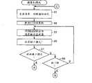
一旦被设定为摄象机模式,CPU83即在图11的步骤S1将水平变焦倍率、垂直变焦倍率和帧数据初始化。此时变焦倍率在垂直方向和水平方向任一个中均成为1倍,至于帧数据则将X大小和Y大小作成“640”和“480”,X座标和Y座标都作成为“0”。因此,由变焦电路75以1倍变焦输出所摄影的图象数据,在存储器控制电路78中被给予要形成相当于监视器帧的动画帧的指示。CPU83然后在步骤S2中指示定时发生器84读出电荷,亦即将CCD成象板激活,然后在步骤S3对存储器控制电路78输出写入请求,将来自变焦电路75的一帧大小的图象数据写入到视频存储区81a。其结果是,在视频存储区81a中形成相当于监视器帧的动画帧,在此动画帧内写入图象数据。Once set to the camera mode, the
CPU83在步骤S5对存储器控制电路78加以读出请求,由视频存储区81a读出全部图象数据。由此,实时摄影对象在整个监视器帧面内被显示。亦即,在监视器80上形成与监视器帧同样大小的动画帧,在此动画帧内显示所摄取的运动图象。CPU83接着在步骤S7和S9分别判断运动图象缩小模式是否被设定和快门按钮89是否被按压。而如果均为“NO”时返回步骤S3。因此,只要操作者没有进行任一键操作,即重复步骤S3和S5的处理,在监视器80上连续显示运动图象。At step S5, the
在由监视器80输出运动图象的状态下操作者如果操作快门按钮89,CPU83的步骤S9判断为“YES”,在图13的步骤S24对定时发生器84指示中止电荷的读出。由此使CCD成象板被截止,视频存储区81a上保持快门按导89被按压时刻的图象数据。CPU38然后在步骤S25由视频存储区81a读出此图象数据加给解压缩电路77进行JPEG压缩。在步骤S25,除图象数据读出外还给解压缩电路77以压缩指示,由此而将图象数据压缩。If the operator operates the
而后在步骤S27判断当前的操作模式是否为运动图象缩小模式,如为“NO”即分别在步骤S30和S31对解压缩电路77指示作成pic文件和向此pic文件收容压缩图象数据。在步骤S31还指示向pic文件写入动画帧的大小数据。从而,在通常的摄象模式中摄取得的图象数据即被收容到被粘贴有识别符“pic”的图象文件“pic OOOP.Jpg”(P为整数)中,动画帧的大小数据被写入在图象文件的标题部分。CPU83将这样的pic文件在步骤S33中记录到存储器插件板82上,返回步骤S1。在步骤S33对存储器插件板82指示写入图象文件。Then in step S27 judge whether current mode of operation is moving image reduction mode, if be " NO " promptly in step S30 and
如果操作者操作菜单设定运动图象缩小模式,CPU83在步骤S7判断为“YES”,在图12的步骤S10截止CCD成象板72,而后在步骤S11执行帧确定处理。If the operator's operation menu sets the moving image reduction mode,
亦即,参看图19,首先在步骤S119由DRAM81的字符区81b读出指针数据,在监器80上显示此指针。接着分别在步骤S121和S125监视光标键86a~86d和确定键88的操作。光标键86a~86d中任一个被操作时,CPU83在步骤S121判断为“YES”,在步骤S123按照键操作变更指针的显示位置,返回步骤S119。另一方面,如确定键88被操作,则在步骤S127判断有未设置标志83a。如未设置标志83a,CPU83在步骤S129将当前的指针位置确定作为动画帧的左上座标,在步骤S131设置标志83a。而后返回步骤S119。That is, referring to FIG. 19, at first in step S119, the pointer data is read out from the
在步骤S127如判断出标志83a设置,CPU83在步骤S133将当前的指针位置确定作为动画帧的右下座标。而在步骤S135将标志83a复位后在步骤S137按下式(2)计算动画帧的X大小和Y大小。亦即,由动画帧的右下座标减去左上X座标求取X大小,由动画帧的右下Y座标减去左上Y座标求取Y大小:If it is judged that the
X大小=右下X座标-左上X座标X size = lower right X coordinate - upper left X coordinate
Y大小=右下Y座标-左上Y座标Y size = lower right Y coordinate - upper left Y coordinate
左上X座标:矩形帧左上角顶点的X座标 (2)Upper left X coordinate: the X coordinate of the upper left corner of the rectangular frame (2)
右上Y座标:矩形帧左上角顶点的Y座标Upper right Y coordinate: the Y coordinate of the upper left corner vertex of the rectangular frame
右下X座标:矩形帧右下角顶点的X座标Bottom right X coordinate: the X coordinate of the vertex of the bottom right corner of the rectangle frame
右下Y座标:矩形帧右下角顶点的Y座标Lower right Y coordinate: the Y coordinate of the lower right vertex of the rectangular frame
回到图12,在步骤S12按下式(3)计算出运动图象的变焦倍率。将算出的变焦倍率设定到变焦电路75。亦即以监视器帧的X大小除被算出的动画帧的X大小求取水平变焦倍率,以监视器帧的Y大小除所算出的动画帧的Y大小求取垂直变焦倍率。Returning to Fig. 12, in step S12, the zoom factor of the moving image is calculated according to equation (3). The calculated zoom magnification is set to the
水平变焦倍率=动画帧的X大小/监视器帧的X大小Horizontal zoom ratio = X size of animation frame / X size of monitor frame
垂直变焦倍率=动画帧的Y大小/监视器帧的Y大小 (3)Vertical zoom ratio = Y size of animation frame/Y size of monitor frame (3)
然后在步骤S13将在步骤S11中得到的帧的左上座标数据和大小数据以及在步骤S12中算出的变焦倍率设定到变焦电路75。这样,即生成为容纳在动画帧内而施行缩小变焦的缩小图象数据。Then, in step S13, the upper left coordinate data and size data of the frame obtained in step S11 and the zoom magnification calculated in step S12 are set to the
CPU83接着在步骤S14给定时发生器84指示读出电荷,将CCD成象板激活。而在步骤S15给予存储器控制电路78写入请求,同时将在步骤S11中求得的X大小、Y大小、左上X座标和左上Y座标的各个数据,亦即动画帧的帧数据加到存储器控制电路78。由此,在视频存储区81a上形成所希望的动画帧,由变焦电路75输出的缩小图象数据被写入动画帧内。在步骤S17,CPU38将读出请求和初始帧数据送至存储器控制电路78,读出视频存储区81a中所存储的全部图象数据。由此,被缩小的运动图象和顺序的图象即在监视器80上显示。亦即,在监视器80上形成的动画帧内显示缩小运动图象,而在监视器帧除开动画帧外的部分显示顺序的图象。而在由操作者所形成的动画帧具有与监视器帧不同的长宽比的情况下,所显示的缩小运动图象就会出现水平方向或垂直方向的畸变。The
CPU83在步骤S19和S23监视光标键86a~86d和快门按钮89的操作,如任一个均未操作即重复步骤S15和S17的处理。由此而在动画帧内显示缩小运动图象。另一方面,如果光标键86a~86d中有一个被操作,在步骤S21将视频存储区81a内的图象数据清除,同时更新帧数据中所含的X座标数据和Y座标数据,亦即动画帧的左上座标数据,返回步骤S15。由此,缩小图象数据的写入位置被变更,结果监视器80上显示的动画帧移动。The
另一方面,如快门按钮89被操作,CPU83在步骤S24截止CCD成象板72,在步骤S25对快门按钮89被按压时刻的缩小图象数据进行JPEG压缩。此时CPU83加给存储器控制电路78动画帧的帧数据和读出请求,指示解压缩电路77作JPEG压缩。因此仅对动画帧内的图象数据加以压缩。在步骤S27中判断当前动作模式是否为运动图象缩小模式,如为“YES”即在步骤S28指示解压缩电路77作成被附加有识别符“syn”的图象文件“syn OOOS.jpg”(S为整数),在步骤S29指示解压缩电路77将压缩图象数据向syn文件收容和将动画帧的大小数据向syn文件写入。因而,小于监视器帧的帧的图象数据被收容进syn文件,而动画帧的大小数据被写入syn文件的标题部分。CPU83将这样容纳有图象数据的syn文件在步骤S33存储进存储器插接板82中,再返回步骤S1。On the other hand, if the
如摄象机模式被设定,即例如图20A中所示被摄象目标的运动图象被显示在监视器80中。这时如操作者设定运动图象缩小模式,即如图20B所示那样消去被摄象对象的显示,代之以在监视器80上显示十字状的指针。此指针根据光标键86a~86d的操作在画面上移动。在图20B所示的指针位置时如果操作员操作确定键88,此指针位置就成为动画帧的左上座标。在左上座标被确定后指针还继续被显示,并按顺光标键86a~86d的操作在画面上移动。操作者如果在使指针移动到图20C所示位置之前按压确定键88,此指针位置即成为动画帧的右下座标。由此,动画帧的位置和大小即被确定。这样,在监视器80上形成动画帧,在此动画帧内缩小显示被摄取对象的运动图象。在此缩小运动图象被显示后,由操作光标键86a~86d,如图20E所示移动缩小运动图象的显示位置。在这样于监视器80中显示缩小运动图象时如果操作者按压快门按钮89,即如图20F所示那样仅将动画帧内的图象记录在存储器插板82上。If the camera mode is set, a moving image of a subject to be photographed is displayed on the
在操作者将模式设定开关87设定到再现侧时,CPU83处理图14~18所示流程。首先在步骤S35将变焦倍率和帧数据初始化,然后在步骤S37由存储器插板81再现pic文件。在步骤S37给存储器插接板友读出指示,例如读出最近的pic文件,由解压缩电路77对pic文件中所收容的压缩图象数据进行扩展。扩展一完成即由解压缩电路77对应存储器控制电路78输入扩展图象数据的写入请求。CPU83在步骤S38在与写入请求相同的定时时刻将初始帧数据输入到存储器控制电路78,将扩展图象数据写入视频存储区81a。由此,在视频存储区81a形成相当于监视器帧的静止画面帧,在此静止画面帧内写入扩展图象数据亦即被再现的静止图象数据。When the operator sets the
CPU83接着在步骤S39给予存储器控制装置78初始帧数据和读出请求,由视频存储区81a读出再现图象数据。由此,再现图象被在监视器80上显示。CPU83然后在步骤S41监视光标键86c或86d的操作,在步骤S45、S47和S49分别监视有无设定动画缩小模式、静止画面剪切模式和静止画面附加模式。如键操作和模式设定均未进行,CPU83重复步骤S39的处理由此在监视器80上连续显示相同的静止图象。Next, the
另一方面,如光标键86c或86d被操作,CPU83在步骤S43由存储器插板82再现另一pic文件,返回步骤S39。此时CPU83还对存储器插件板82给予读出指示读出所希望的pic文件,由解压缩电路77扩展pic文件中所容纳的压缩图象数据。扩展图象数据在步骤S38被写到视频存储区81a上。由此,监视器80上显示的再现图象被更新。另一方面,如选择动画缩小模式即转移到步骤S51,如选择静止画面剪切模式转移到步骤S73,而如选择静止画面附加模式则转移到步骤S88。On the other hand, if the cursor key 86c or 86d is operated, the
如动画缩小模式被设定CPU83在步骤S51按图19所示子例程进行动画帧确定处理,在步骤S53按上述式(3)计算变焦倍率。并在步骤S54将帧的左上座标数据和大小数以及变焦倍率设定到变焦电路75。由此,由变焦电路75输出对应于动画帧的大小的缩小图象数据。CPU83再在步骤S58将写入请求和在步骤S51所确定的动画帧的帧数据设定到存储器控制电路78,将缩小图象写入视频存储区81a中形成的动画帧内。由此,在视频存储区81a中缩小图象数据被合成到已写入的再现图象数据上。CPU83接着在步骤S57将读出请求和初始帧数据加给存则器空制电路78,读出DRAM81中所存储的全部图象数据,由监视器80输出。如果操作者没有操作光标键86a~86d和快门按钮89中任一个,CPU83即重复步骤S55和S5)的处理。由此,在监示器80中所形成的动画帧内显示运动图象,在监视器帧的除动画帧外的部分显示静止图象。If the animation reduction mode is set, the
操作者如操作光标键86a~86d中任一个,CPU83在步骤S59判断为“YES”。而后在步骤S61由存储器插板82再现与前次相同的pic文件,同时在步骤S62将初始帧数据输入到存储器控制电路78将再现图象写入视频存储区81a。并在步骤S63更新动画帧的左上X座标和左上Y座标,返回步骤S55。在步骤S55将缩小图象写入位置移动后的动画帧,在步骤S57读出视频存储区81a的全部图象数据。由此,因为每次光标键86a~86d被操作均重复pic文件的再现,所以在动画帧移动后不会缺少静止图象。If the operator operates any of the
操作者如操作快门按钮89,CPU83在步骤S65判断为“YES”,在步骤S67对视频存储区81a上存储的全部图象数据进行JPEG压缩。此时。CPU83给予存储器控制电路78读出请求和初始帧数据,给予解压缩电路77压缩指示。由此,生成压缩图象数据。接着在步骤S68指示作成pic文件,在步骤S69指示向pic文件收容压缩图象数据和写入监视器帧的帧数据。此后在步骤S71将收容有压缩图象数据的pic文件存储到存储器插板82,返回步骤S35。If the operator operates the
如图21A中所示在监视器80显示有再现图象的状态下如设定动画缩小模式,即如图21B所示那样在监视器80上显示指针。此指针还按照光标键86a~86d的操作移动,按照确定键70的操作确定动画帧的左上座标和右下座标。如在图21B和21C所示位置操作确定键,即如图21D所示形成动画帧,在其中显示被摄对象的缩小动画象。所形成的动画帧按照光标键86a~86d的操作在画面上移动。因为按照光标键86a~86d的操作重复再现同样的静止图象,所以即使移动动画帧也不会丢失由移动前的动画帧覆盖的静止图象。在使动画帧移动到图21E所示位置后如按压快门按钮89,即如图21F中所示,所显示的全部图象均被记录进存储器插板82。As shown in FIG. 21A, when the reproduced image is displayed on the
回到图14,和在步骤47判断为已设定静止画面剪切模式,CPU83在图16的步骤S73处理图19中所示的子例程,确定静止画面帧。而后在步骤S75由视频存储区81a读出静止图象数据,同时由字符区81b读出静止画面帧的字符数据,输出到监视器80。由此,在静止图象上合成显示静止画面帧。这时如操作者操作光标键86a~86d,CPU83在步骤S77判断为“YES”,在步骤S79更新静止画面帧的左上座标数据。亦即更新加给存储器控制电路78的帧数据的X座标和Y座标。而后返回步骤S75。因此,静止画面帧的监视器80上移动。另一方面,操作者如果操作快门按钮89,CPU83在步骤S83将静止画面帧内的图象数据加给解压缩电路77,作JPEG压缩。此后,在步骤S84作成syn文件,在步骤S85将压缩图象数据收容到此syn文件中。再在步骤S87将收容有压缩图象数据的syn文件存储到存储器插件板82,返回步骤S35。Returning to FIG. 14, and judging in
在如图22A中所示那样由存储器插件板82再现的静止图象被显示的状态下如静止画面剪切模式被设定,即如图22B中所示显示指针。与上述同样如操作光标键86a~86d和确定键88,静止画面帧的左上座标和右下座标即被确定。并如图22d那样在监视器80上显示静止画面帧。此静止画面帧按照光标键86a~86d的操作在监视器帧内移动。在如图22D中所示那样显示静止画面帧的状态下如快门按钮89被按压,即如图22E中所示仅将静止画面帧内的部分静止图象记录到存储器插件板82。In a state where a still image reproduced by the
回到图14,在步骤S49如判断静止画面粘贴模式被选择,CPUS3在图17所示步骤S88由存储器插件板82读出某一syn文件,由其syn文件的标题中检测所收容的部分数据的帧大小数据。CPU83还在步骤S89确定为使此部分静止图象在监视器帧的中央显示的静止画面帧的左上座标。这样,静止画面帧的帧数据被确定,CPU83在步骤S90再现同样的syn文件。亦即,在存储器插板82读出同样的syn文件,将所读出syn文件中所含的压缩图象数据由解压缩电路77扩展。而后在步骤S91将扩展图象数据写入视频存器区81a。在向视频存储区81a写入时,CPU83将写入请求以及在步骤S88和S89中所确定的帧数据加给存储器控制电路28。因此,在视频存储区81a形成静止画面帧,被扩展的部分静止图象数据被写入此静止画面帧内。Get back to Fig. 14, in step S49, select as judging still picture pasting mode, CPUS3 reads a certain syn file by memory plug-in
在步骤S91,加给存储器控制电路78读出请求和初始帧数据,将视频存储区81a的全部图象数据输出到监视器80。据此,在静止画面粘贴模式设定前所显示的静止图象上形成静止画面帧,将由存储器插板82重新再现的部分静止图象在此静止画面帧内加以合成。此时如操作者操作光标键86a或86b,部分静止图象即被切换。CPU83在步骤S94再现与首次同样的pic文件,在步骤S95将初始帧数据输入到存储器控制电路78将再现图象数据写入视频存储区81a。然后在步骤S96和S97分别进行与上述步骤S88和S89同样的处理,更新静止画面帧的帧数据。此后,在步骤S97再现其他syn文件,返回步骤S91。如果这将再现的部分静止图象小于前次的部分静止图象,因为部分静止图象下面显示的静止图象的一部分丢失,所以在相同pic文件被再现后,再现别一syn文件。In step S91, a read request and initial frame data are supplied to the
另一方面,如果操作者操作光标键86c或86d,部分静止图象下面所显示的静止图象即被更新。此时CPU83在步骤S99判断为“YES”,在步骤100再现根据键操作的另一pic文件,在步骤S101将再现图象数据写入视频存储区81a。然后在步骤S102再现相同的SYn文件,返回步骤S91。这样就能选择所希望的二个静止图象。On the other hand, if the operator operates the cursor key 86c or 86d, the still image displayed below the part of the still image is updated. Now CPU83 is judged as " YES " in step S99, reproduces another pic file according to key operation in step S100, writes the reproduced image data in
在所希望的二个静止图象被显示时如确定键88被按压,CPU83在步骤S103判断为“YES”,进行步骤S105。在步骤S105,与步骤S91同样地将视频存储区81a的全部图象数据输出到监视器80。此后在步骤S106判断光标键86a~86d中有无被操作的,如为“YES”,在步骤S108更新加给存储器控制电路78的帧数据的左上座标。If the
接着,在步骤S109再现与前次相同的pic文件,在步骤110将再现图象数据根据初始帧数据写入视频存储区81a。再在步骤S111再现与前次同样的syn文件,在步骤S112将再现图象亦即部分静止图象数据写入移动后的静止画面帧内。在步骤S112,与上述同样地加给存储器控制电路78更新后的帧数据和写入请求,在由此形成的静止画面帧内写入部分静止图象数据。再返回步骤S105。这样,部分静止图象的显示位置按照键操作被变更。Next, in step S109, reproduce the same pic file as last time, and in
如操作者操作快门按钮89,CPU83在步骤S113对存储在视频存储区81a的全部图象数据进行压缩处理,在步骤S114作成pic文件,再在步骤S115将压缩图象数据收容进pic文件。然后在步骤S117将收容此压缩图象数据的pic文件存储到存储器插件板82,返回步骤S35。If the operator operates the
在如图23A中所示由pic文件再现的静止图象在监视器32上显示的状态下如静止图面附加模式被设定,即如图23B那样,由SYn文件再现的部分静止图象被合成到pic文件的静止图象。在此状态中如操作光标键86a或86b,部分静止图象即被切换,如操作光标键86c或86d,部分静止图象的下面的静止图象被切换。在合成的二个图象被确定后如操作光标键86a~86d,即如图23C中所示部分静止图象移动。以此部分静止图象被配置到所希望位置时刻如按压快门按钮89,即如图23D中所示,所显示的全部静止图象被记录到存储器插件板82。As shown in FIG. 23A, the still image reproduced by the pic file is displayed on the
在此实施例中,虽然是使得在动画帧中显示缩小运动图象,但也可以在动画帧内显示1倍的运动图象。亦即,也可以在通常的摄象机模式仅将监视器帧内所显示的运动图象的一部分在动画帧内显示。在这种情况下,按照动画帧的位置变更所显示的运动图象。In this embodiment, although the zoomed-in moving picture is displayed in the moving picture frame, it is also possible to display the 1-fold moving picture in the moving picture frame. That is, it is also possible to display only a part of the moving image displayed on the monitor frame in the animation frame in the normal camera mode. In this case, the displayed moving image is changed according to the position of the animation frame.
在此实施例中虽然是将动画帧和静止画面帧形成为矩形形状,但动画帧和静止画面帧也可形成为园形。在此情况下,帧的大小可由园的半径指定,帧的位置可由中心座标指定。Although the animation frame and the still picture frame are formed in a rectangular shape in this embodiment, the animation frame and the still picture frame may also be formed in a circular shape. In this case, the size of the frame can be specified by the radius of the circle, and the position of the frame can be specified by the center coordinates.
这里所揭示的实施形态应被看作为全部各方面均是作为示例而不是限制性的。本发明的范围并不在于上述的说明中而是由权利要求的范围来表明,与权利要求的范围等同的内容和此范围内的所有变更均应被看作被包含在其中。The embodiments disclosed here should be considered as examples and not restrictive in all aspects. The scope of the present invention is shown not by the above-mentioned description but by the scope of the claims, and the content equivalent to the scope of the claims and all changes within the range should be considered to be included therein.
Claims (22)
Applications Claiming Priority (9)
| Application Number | Priority Date | Filing Date | Title |
|---|---|---|---|
| JP65051/1998 | 1998-03-16 | ||
| JP6505198 | 1998-03-16 | ||
| JP65051/98 | 1998-03-16 | ||
| JP10114909AJP2995033B2 (en) | 1998-03-16 | 1998-04-24 | Digital camera |
| JP114909/98 | 1998-04-24 | ||
| JP114909/1998 | 1998-04-24 | ||
| JP125089/98 | 1998-05-07 | ||
| JP10125089AJP3071176B2 (en) | 1998-05-07 | 1998-05-07 | Digital camera |
| JP125089/1998 | 1998-05-07 |
Related Child Applications (2)
| Application Number | Title | Priority Date | Filing Date |
|---|---|---|---|
| CNB031457576ADivisionCN1254954C (en) | 1998-03-16 | 1999-03-16 | Digital camera capable of image processing |
| CNB031457568ADivisionCN1233148C (en) | 1998-03-16 | 1999-03-16 | Digita pick-up device able to process image |
Publications (2)
| Publication Number | Publication Date |
|---|---|
| CN1237062Atrue CN1237062A (en) | 1999-12-01 |
| CN1164084C CN1164084C (en) | 2004-08-25 |
Family
ID=27298648
Family Applications (3)
| Application Number | Title | Priority Date | Filing Date |
|---|---|---|---|
| CNB991058224AExpired - LifetimeCN1164084C (en) | 1998-03-16 | 1999-03-16 | digital camera capable of image processing |
| CNB031457568AExpired - LifetimeCN1233148C (en) | 1998-03-16 | 1999-03-16 | Digita pick-up device able to process image |
| CNB031457576AExpired - LifetimeCN1254954C (en) | 1998-03-16 | 1999-03-16 | Digital camera capable of image processing |
Family Applications After (2)
| Application Number | Title | Priority Date | Filing Date |
|---|---|---|---|
| CNB031457568AExpired - LifetimeCN1233148C (en) | 1998-03-16 | 1999-03-16 | Digita pick-up device able to process image |
| CNB031457576AExpired - LifetimeCN1254954C (en) | 1998-03-16 | 1999-03-16 | Digital camera capable of image processing |
Country Status (5)
| Country | Link |
|---|---|
| US (3) | US7057658B1 (en) |
| EP (2) | EP1315371B1 (en) |
| KR (1) | KR100312575B1 (en) |
| CN (3) | CN1164084C (en) |
| DE (2) | DE69908005T2 (en) |
Cited By (3)
| Publication number | Priority date | Publication date | Assignee | Title |
|---|---|---|---|---|
| CN1312908C (en)* | 2002-04-17 | 2007-04-25 | 精工爱普生株式会社 | Digital camera |
| CN100428776C (en)* | 2004-03-26 | 2008-10-22 | 卡西欧计算机株式会社 | Camera device and camera control method |
| CN101197922B (en)* | 2006-12-04 | 2011-05-04 | 华晶科技股份有限公司 | Method for accelerating image processing and digital image capture device thereof |
Families Citing this family (56)
| Publication number | Priority date | Publication date | Assignee | Title |
|---|---|---|---|---|
| CN1647507A (en)* | 2002-04-17 | 2005-07-27 | 精工爱普生株式会社 | Digital camera |
| JP2004015286A (en) | 2002-06-05 | 2004-01-15 | Seiko Epson Corp | Digital camera |
| US20050212945A1 (en)* | 2002-07-29 | 2005-09-29 | Seiko Epson Corporation | Digital camera |
| WO2004014067A1 (en)* | 2002-08-01 | 2004-02-12 | Seiko Epson Corporation | Digital camera |
| JP2004094498A (en)* | 2002-08-30 | 2004-03-25 | Rohm Co Ltd | Image display system, and display |
| JP3948387B2 (en)* | 2002-10-24 | 2007-07-25 | 松下電器産業株式会社 | Digital camera and mobile phone device with digital camera |
| US7844076B2 (en) | 2003-06-26 | 2010-11-30 | Fotonation Vision Limited | Digital image processing using face detection and skin tone information |
| US7471846B2 (en)* | 2003-06-26 | 2008-12-30 | Fotonation Vision Limited | Perfecting the effect of flash within an image acquisition devices using face detection |
| US7792970B2 (en) | 2005-06-17 | 2010-09-07 | Fotonation Vision Limited | Method for establishing a paired connection between media devices |
| US7440593B1 (en)* | 2003-06-26 | 2008-10-21 | Fotonation Vision Limited | Method of improving orientation and color balance of digital images using face detection information |
| US7574016B2 (en)* | 2003-06-26 | 2009-08-11 | Fotonation Vision Limited | Digital image processing using face detection information |
| US7269292B2 (en) | 2003-06-26 | 2007-09-11 | Fotonation Vision Limited | Digital image adjustable compression and resolution using face detection information |
| US8494286B2 (en)* | 2008-02-05 | 2013-07-23 | DigitalOptics Corporation Europe Limited | Face detection in mid-shot digital images |
| US8948468B2 (en) | 2003-06-26 | 2015-02-03 | Fotonation Limited | Modification of viewing parameters for digital images using face detection information |
| US7565030B2 (en)* | 2003-06-26 | 2009-07-21 | Fotonation Vision Limited | Detecting orientation of digital images using face detection information |
| US8498452B2 (en) | 2003-06-26 | 2013-07-30 | DigitalOptics Corporation Europe Limited | Digital image processing using face detection information |
| US20050041110A1 (en)* | 2003-08-21 | 2005-02-24 | Frank Liebenow | Digital camera user interface and method |
| US7656429B2 (en)* | 2004-02-04 | 2010-02-02 | Hewlett-Packard Development Company, L.P. | Digital camera and method for in creating still panoramas and composite photographs |
| US7391445B2 (en)* | 2004-03-31 | 2008-06-24 | Magix Ag | System and method of creating multilayered digital images in real time |
| US20060077266A1 (en)* | 2004-10-08 | 2006-04-13 | Nokia Corporation | Image processing in a communication device having a camera |
| KR101058024B1 (en)* | 2004-11-18 | 2011-08-19 | 삼성전자주식회사 | Digital photographing apparatus in which icons are adaptively displayed and control method thereof |
| US7733405B2 (en)* | 2005-02-10 | 2010-06-08 | Seiko Epson Corporation | Apparatus and method for resizing an image |
| US20060197851A1 (en)* | 2005-03-07 | 2006-09-07 | Paul Vlahos | Positioning a subject with respect to a background scene in a digital camera |
| JP4805596B2 (en)* | 2005-03-31 | 2011-11-02 | 株式会社東芝 | Camera device |
| US20070065114A1 (en)* | 2005-09-19 | 2007-03-22 | Xin Wen | Video camera capable of uninterrupted recording |
| US20070153093A1 (en)* | 2005-12-30 | 2007-07-05 | Mediatek Incorporation | Apparatus and method for image capturing with an image scaling unit to scale a portion of an image |
| CN101072286A (en)* | 2006-05-08 | 2007-11-14 | 宏达国际电子股份有限公司 | Electronic device capable of zooming images in situ and application method thereof |
| EP2033142B1 (en) | 2006-06-12 | 2011-01-26 | Tessera Technologies Ireland Limited | Advances in extending the aam techniques from grayscale to color images |
| US7956907B2 (en)* | 2006-08-23 | 2011-06-07 | Panasonic Corporation | Image capture device with low-frequency noise suppression |
| US7764291B1 (en)* | 2006-08-30 | 2010-07-27 | Adobe Systems Incorporated | Identification of common visible regions in purposing media for targeted use |
| US8055067B2 (en) | 2007-01-18 | 2011-11-08 | DigitalOptics Corporation Europe Limited | Color segmentation |
| KR100814390B1 (en)* | 2007-02-15 | 2008-03-18 | 삼성전자주식회사 | Memory device and manufacturing method thereof. |
| KR100850273B1 (en)* | 2007-03-08 | 2008-08-04 | 삼성전자주식회사 | Multi-bit electromechanical memory device and manufacturing method thereof |
| US20080231740A1 (en)* | 2007-03-21 | 2008-09-25 | Mcintyre Dale F | Camera with multiple displays |
| US20080231741A1 (en)* | 2007-03-21 | 2008-09-25 | Mcintyre Dale F | Camera with multiple displays |
| USD609714S1 (en) | 2007-03-22 | 2010-02-09 | Fujifilm Corporation | Electronic camera |
| WO2008131823A1 (en)* | 2007-04-30 | 2008-11-06 | Fotonation Vision Limited | Method and apparatus for automatically controlling the decisive moment for an image acquisition device |
| KR100876948B1 (en)* | 2007-05-23 | 2009-01-09 | 삼성전자주식회사 | Multi-bit electromechanical memory device and manufacturing method thereof |
| KR100876088B1 (en)* | 2007-05-23 | 2008-12-26 | 삼성전자주식회사 | Multi-bit electromechanical memory device and manufacturing method thereof |
| JP4998312B2 (en)* | 2008-02-15 | 2012-08-15 | 富士通セミコンダクター株式会社 | Image processing apparatus, imaging apparatus, and image processing method |
| US7855737B2 (en)* | 2008-03-26 | 2010-12-21 | Fotonation Ireland Limited | Method of making a digital camera image of a scene including the camera user |
| JP2009284309A (en)* | 2008-05-23 | 2009-12-03 | Casio Comput Co Ltd | Imaging device, display control program, and display control method |
| KR20100062575A (en)* | 2008-12-02 | 2010-06-10 | 삼성테크윈 주식회사 | Method to control monitoring camera and control apparatus using the same |
| KR101618759B1 (en)* | 2008-12-24 | 2016-05-09 | 삼성전자주식회사 | Apparatus and method for capturing image |
| JP5457092B2 (en)* | 2009-07-03 | 2014-04-02 | オリンパスイメージング株式会社 | Digital camera and composite image display method of digital camera |
| US8379917B2 (en) | 2009-10-02 | 2013-02-19 | DigitalOptics Corporation Europe Limited | Face recognition performance using additional image features |
| JP5054747B2 (en)* | 2009-10-06 | 2012-10-24 | シャープ株式会社 | Image display system |
| US20130327831A1 (en)* | 2012-06-11 | 2013-12-12 | Datalogic ADC, Inc. | Dynamic imager switching |
| JP6160996B2 (en) | 2012-09-12 | 2017-07-12 | パナソニックIpマネジメント株式会社 | Imaging device |
| US8902325B2 (en)* | 2012-10-19 | 2014-12-02 | Facebook, Inc. | Camera preview via video tag |
| KR101990036B1 (en) | 2012-10-31 | 2019-06-17 | 엘지전자 주식회사 | Mobile terminal and control method thereof |
| US9137461B2 (en)* | 2012-11-30 | 2015-09-15 | Disney Enterprises, Inc. | Real-time camera view through drawn region for image capture |
| CN103049175B (en)* | 2013-01-22 | 2016-08-10 | 华为终端有限公司 | Preview screen presentation method, device and terminal |
| US9350924B2 (en) | 2014-08-25 | 2016-05-24 | John G. Posa | Portable electronic devices with integrated image/video compositing |
| DE102016109179B4 (en) | 2015-05-29 | 2023-08-03 | Canon Kabushiki Kaisha | Image pickup device and imaging device |
| CN106227353B (en)* | 2016-08-05 | 2019-07-09 | 成都市极米科技有限公司 | A kind of operating mode control method and system |
Family Cites Families (32)
| Publication number | Priority date | Publication date | Assignee | Title |
|---|---|---|---|---|
| US4408301A (en)* | 1979-11-06 | 1983-10-04 | Tokyo Shibaura Denki Kabushiki Kaisha | Picture information filing system |
| US5732186A (en)* | 1986-06-20 | 1998-03-24 | Canon Kabushiki Kaisha | Image signal recording/reproducing apparatus having special-effects-processing capability |
| JPS6414675A (en) | 1987-07-08 | 1989-01-18 | Sharp Kk | Image synthesizing layout device |
| JPS6414675U (en) | 1987-07-18 | 1989-01-25 | ||
| JPH0222967A (en) | 1988-07-12 | 1990-01-25 | Konica Corp | Camera |
| JPH0775898B2 (en) | 1988-11-11 | 1995-08-16 | 沖電気工業株式会社 | Serial printer |
| US5146334A (en)* | 1989-02-27 | 1992-09-08 | Canon Kabushiki Kaisha | Video signal processing device for image editing using memory |
| JPH0322679A (en) | 1989-06-19 | 1991-01-31 | Matsushita Electric Ind Co Ltd | electronic still camera |
| JPH0342979A (en) | 1989-07-10 | 1991-02-25 | Konica Corp | Still picture recorder |
| JPH0468680A (en) | 1990-07-03 | 1992-03-04 | Matsushita Electric Ind Co Ltd | television receiver |
| JP3037383B2 (en)* | 1990-09-03 | 2000-04-24 | キヤノン株式会社 | Image processing system and method |
| KR930007065B1 (en) | 1991-01-30 | 1993-07-26 | 삼성전자 주식회사 | Screen editing device during playback in electronic camera system |
| JP2934518B2 (en) | 1991-03-15 | 1999-08-16 | 正光 市橋 | Video camera controller |
| DE69222580T2 (en)* | 1991-07-15 | 1998-04-16 | Hitachi Ltd | Image encoder decoder and teleconferencing terminal |
| US5420635A (en)* | 1991-08-30 | 1995-05-30 | Fuji Photo Film Co., Ltd. | Video camera, imaging method using video camera, method of operating video camera, image processing apparatus and method, and solid-state electronic imaging device |
| JPH0589214A (en)* | 1991-09-30 | 1993-04-09 | Sanyo Electric Co Ltd | Editing device |
| US5262856A (en)* | 1992-06-04 | 1993-11-16 | Massachusetts Institute Of Technology | Video image compositing techniques |
| JPH066712A (en) | 1992-06-23 | 1994-01-14 | Matsushita Electric Ind Co Ltd | Method for displaying picture expanding part |
| US5905530A (en)* | 1992-08-24 | 1999-05-18 | Canon Kabushiki Kaisha | Image pickup apparatus |
| JPH06334960A (en) | 1993-05-21 | 1994-12-02 | Kyocera Corp | Multiscreen display system |
| US5710954A (en)* | 1994-02-17 | 1998-01-20 | Olympus Optical Co., Ltd. | Camera system having function for photographing image linked to electronic image |
| US5477264A (en)* | 1994-03-29 | 1995-12-19 | Eastman Kodak Company | Electronic imaging system using a removable software-enhanced storage device |
| JP3607727B2 (en) | 1994-09-19 | 2005-01-05 | オリンパス株式会社 | Video signal playback device |
| EP0713331B1 (en)* | 1994-11-17 | 2001-03-14 | Canon Kabushiki Kaisha | Camera control device and method |
| US6359649B1 (en)* | 1995-04-04 | 2002-03-19 | Canon Kabushiki Kaisa | Video camera integrated with still camera |
| JP3600864B2 (en) | 1996-09-12 | 2004-12-15 | 株式会社ニコン | Image recording and playback device |
| US5963204A (en)* | 1996-09-20 | 1999-10-05 | Nikon Corporation | Electronic camera with reproduction and display of images at the same timing |
| JPH10174031A (en)* | 1996-12-10 | 1998-06-26 | Sharp Corp | Image recording and playback device |
| US6621524B1 (en) | 1997-01-10 | 2003-09-16 | Casio Computer Co., Ltd. | Image pickup apparatus and method for processing images obtained by means of same |
| JPH10234020A (en)* | 1997-02-21 | 1998-09-02 | Canon Inc | Image transmission method and apparatus, and image transmission system |
| JP3786242B2 (en)* | 1997-07-14 | 2006-06-14 | 富士写真フイルム株式会社 | Image processing method and apparatus, image reproduction method and apparatus, and image confirmation apparatus used in the method |
| JP4286475B2 (en) | 2001-08-10 | 2009-07-01 | 株式会社スズキ麺工 | Snoring equipment |
- 1999
- 1999-03-15EPEP03001735Apatent/EP1315371B1/ennot_activeExpired - Lifetime
- 1999-03-15USUS09/267,398patent/US7057658B1/ennot_activeExpired - Lifetime
- 1999-03-15DEDE69908005Tpatent/DE69908005T2/ennot_activeExpired - Lifetime
- 1999-03-15EPEP99105263Apatent/EP0944248B1/ennot_activeExpired - Lifetime
- 1999-03-15DEDE69931973Tpatent/DE69931973T2/ennot_activeExpired - Lifetime
- 1999-03-16CNCNB991058224Apatent/CN1164084C/ennot_activeExpired - Lifetime
- 1999-03-16CNCNB031457568Apatent/CN1233148C/ennot_activeExpired - Lifetime
- 1999-03-16CNCNB031457576Apatent/CN1254954C/ennot_activeExpired - Lifetime
- 1999-03-16KRKR1019990008885Apatent/KR100312575B1/ennot_activeExpired - Lifetime
- 2006
- 2006-04-11USUS11/401,419patent/US7394496B2/ennot_activeExpired - Fee Related
- 2008
- 2008-05-21USUS12/153,582patent/US7733388B2/ennot_activeExpired - Fee Related
Cited By (3)
| Publication number | Priority date | Publication date | Assignee | Title |
|---|---|---|---|---|
| CN1312908C (en)* | 2002-04-17 | 2007-04-25 | 精工爱普生株式会社 | Digital camera |
| CN100428776C (en)* | 2004-03-26 | 2008-10-22 | 卡西欧计算机株式会社 | Camera device and camera control method |
| CN101197922B (en)* | 2006-12-04 | 2011-05-04 | 华晶科技股份有限公司 | Method for accelerating image processing and digital image capture device thereof |
Also Published As
| Publication number | Publication date |
|---|---|
| US7394496B2 (en) | 2008-07-01 |
| CN1520159A (en) | 2004-08-11 |
| DE69931973T2 (en) | 2007-02-01 |
| EP0944248A2 (en) | 1999-09-22 |
| EP1315371B1 (en) | 2006-06-14 |
| CN1164084C (en) | 2004-08-25 |
| DE69908005T2 (en) | 2004-04-01 |
| DE69908005D1 (en) | 2003-06-26 |
| US20060181630A1 (en) | 2006-08-17 |
| CN1254954C (en) | 2006-05-03 |
| DE69931973D1 (en) | 2006-07-27 |
| EP0944248A3 (en) | 2000-04-12 |
| EP1315371A1 (en) | 2003-05-28 |
| KR19990077934A (en) | 1999-10-25 |
| US7057658B1 (en) | 2006-06-06 |
| CN1529496A (en) | 2004-09-15 |
| US7733388B2 (en) | 2010-06-08 |
| US20080231717A1 (en) | 2008-09-25 |
| KR100312575B1 (en) | 2001-11-03 |
| CN1233148C (en) | 2005-12-21 |
| EP0944248B1 (en) | 2003-05-21 |
Similar Documents
| Publication | Publication Date | Title |
|---|---|---|
| CN1237062A (en) | digital camera capable of image processing | |
| US6188432B1 (en) | Information processing method and apparatus for displaying and zooming an object image and a line drawing | |
| US20030071904A1 (en) | Image capturing apparatus, image reproducing apparatus and program product | |
| JPH10240436A (en) | Information processing device and recording medium | |
| JPH104531A (en) | Information processing device | |
| JP2009171268A (en) | Electronic camera | |
| JP2003274335A (en) | Information recording device | |
| US20050264668A1 (en) | Electronic apparatus with image capturing function and image display method | |
| CN100440927C (en) | photographic device, photographic method | |
| JPH10336494A (en) | Digital camera with zoom display function | |
| JP4696614B2 (en) | Image display control device and program | |
| US7254776B2 (en) | Information processing apparatus | |
| JP5003803B2 (en) | Image output apparatus and program | |
| JP2012124614A (en) | Imaging apparatus and imaging apparatus control method | |
| JP4838644B2 (en) | Imaging apparatus, control method thereof, and program | |
| JP4948011B2 (en) | Imaging apparatus, control method therefor, computer program, and storage medium | |
| JP2003333425A (en) | Camera | |
| JP2005347885A (en) | Imaging apparatus, imaging range adjustment method, and program | |
| JP4798229B2 (en) | Electronic camera | |
| JP5115523B2 (en) | Imaging apparatus, imaging range adjustment method, and program | |
| JPH10224677A (en) | Information processing device and recording medium | |
| JP2003204454A (en) | Image processor and electronic camera | |
| JPH11317892A (en) | Digital camera | |
| JP2003087721A (en) | Electronic camera | |
| JPH10224691A (en) | Information processing device and recording medium |
Legal Events
| Date | Code | Title | Description |
|---|---|---|---|
| C10 | Entry into substantive examination | ||
| SE01 | Entry into force of request for substantive examination | ||
| C06 | Publication | ||
| PB01 | Publication | ||
| C14 | Grant of patent or utility model | ||
| GR01 | Patent grant | ||
| REG | Reference to a national code | Ref country code:HK Ref legal event code:GR Ref document number:1056728 Country of ref document:HK | |
| ASS | Succession or assignment of patent right | Owner name:XACTI CO., LTD. Free format text:FORMER OWNER: SANYO ELECTRIC CO., LTD. Effective date:20140902 | |
| C41 | Transfer of patent application or patent right or utility model | ||
| TR01 | Transfer of patent right | Effective date of registration:20140902 Address after:Osaka Japan Patentee after:Hyun Hyun Lee Address before:Osaka Japan Patentee before:Sanyo Electric Co., Ltd. | |
| CX01 | Expiry of patent term | Granted publication date:20040825 | |
| CX01 | Expiry of patent term |