CN1236539C - Charger - Google Patents
ChargerDownload PDFInfo
- Publication number
- CN1236539C CN1236539CCNB011445467ACN01144546ACN1236539CCN 1236539 CCN1236539 CCN 1236539CCN B011445467 ACNB011445467 ACN B011445467ACN 01144546 ACN01144546 ACN 01144546ACN 1236539 CCN1236539 CCN 1236539C
- Authority
- CN
- China
- Prior art keywords
- charger
- battery
- magnetic field
- charging control
- control circuit
- Prior art date
- Legal status (The legal status is an assumption and is not a legal conclusion. Google has not performed a legal analysis and makes no representation as to the accuracy of the status listed.)
- Expired - Fee Related
Links
Images


Classifications
- H—ELECTRICITY
- H02—GENERATION; CONVERSION OR DISTRIBUTION OF ELECTRIC POWER
- H02J—CIRCUIT ARRANGEMENTS OR SYSTEMS FOR SUPPLYING OR DISTRIBUTING ELECTRIC POWER; SYSTEMS FOR STORING ELECTRIC ENERGY
- H02J7/00—Circuit arrangements for charging or depolarising batteries or for supplying loads from batteries
- H02J7/0029—Circuit arrangements for charging or depolarising batteries or for supplying loads from batteries with safety or protection devices or circuits
- H02J7/0031—Circuit arrangements for charging or depolarising batteries or for supplying loads from batteries with safety or protection devices or circuits using battery or load disconnect circuits
- H—ELECTRICITY
- H02—GENERATION; CONVERSION OR DISTRIBUTION OF ELECTRIC POWER
- H02J—CIRCUIT ARRANGEMENTS OR SYSTEMS FOR SUPPLYING OR DISTRIBUTING ELECTRIC POWER; SYSTEMS FOR STORING ELECTRIC ENERGY
- H02J9/00—Circuit arrangements for emergency or stand-by power supply, e.g. for emergency lighting
- H02J9/005—Circuit arrangements for emergency or stand-by power supply, e.g. for emergency lighting using a power saving mode
- H02J9/007—Detection of the absence of a load
- Y—GENERAL TAGGING OF NEW TECHNOLOGICAL DEVELOPMENTS; GENERAL TAGGING OF CROSS-SECTIONAL TECHNOLOGIES SPANNING OVER SEVERAL SECTIONS OF THE IPC; TECHNICAL SUBJECTS COVERED BY FORMER USPC CROSS-REFERENCE ART COLLECTIONS [XRACs] AND DIGESTS
- Y10—TECHNICAL SUBJECTS COVERED BY FORMER USPC
- Y10S—TECHNICAL SUBJECTS COVERED BY FORMER USPC CROSS-REFERENCE ART COLLECTIONS [XRACs] AND DIGESTS
- Y10S320/00—Electricity: battery or capacitor charging or discharging
- Y10S320/12—Precharging analysis, e.g. determining presence of battery
Landscapes
- Engineering & Computer Science (AREA)
- Power Engineering (AREA)
- Charge And Discharge Circuits For Batteries Or The Like (AREA)
- Secondary Cells (AREA)
- Battery Mounting, Suspending (AREA)
Abstract
Description
Translated fromChinese技术领域technical field
本发明涉及对二次电池充电用的充电器。The present invention relates to a charger for charging a secondary battery.
背景技术Background technique
在常规充电器中,即使二次电池处于电气不连接的状态,只要输入端有电源供给,在充电用的输出端子上仍有电压输出。In a conventional charger, even if the secondary battery is in a state of being electrically disconnected, as long as there is power supply at the input end, there is still a voltage output at the output terminal for charging.
在多数充电器中,当二次电池在电气上未被连接时,充电用的输出端子被保持为暴露状态。因此在输出端子上由金属或类似物引起短路的可能性是较大的。如上面所述,即使二次电池处于电气不连接状态,充电器仍输出充电电压。所以,一旦发生输出端子短路,就可能发生充电器内部的异常发热或充电器内部元件的热破坏。In most chargers, when the secondary battery is not electrically connected, the output terminal for charging is kept exposed. Therefore, the possibility of causing a short circuit by metal or the like on the output terminals is high. As described above, even if the secondary battery is in an electrically disconnected state, the charger outputs the charging voltage. Therefore, if the output terminal is short-circuited, abnormal heat generation inside the charger or thermal damage to internal components of the charger may occur.
另一方面,常规充电器甚至能对专用的二次电池以外的电池充电。然而,当专用的二次电池以外的二次电池被错误地充电时,有可能引致二次电池的性能降低,引致二次电池损坏或液漏。On the other hand, conventional chargers can charge even batteries other than dedicated secondary batteries. However, when a secondary battery other than the dedicated secondary battery is incorrectly charged, the performance of the secondary battery may be degraded, resulting in damage or liquid leakage of the secondary battery.
发明内容Contents of the invention
本发明是针对上述问题的研究完成的。因此,本发明的目的是提供一种充电器,它能避免二次电池被连接时输出端短路的可能性,并能防止使用除专用的二次电池之外的二次电池。The present invention is accomplished in view of the research of the above-mentioned problems. Accordingly, it is an object of the present invention to provide a charger which can avoid the possibility of a short circuit at the output terminal when a secondary battery is connected and which can prevent the use of a secondary battery other than a dedicated secondary battery.
为了达到上述和其他目的,提供一种充电器,其中作为二次电池的电池部件可拆卸地装入充电器本体,而且所述充电器侧的第一和第二输出端子、以及电池部件侧的正极端子和负极端子相互连接,从而使充电电流通过第一和第二输出端子从所述充电器的充电控制电路输送到电池部件,以对电池部件进行充电。所述充电器包括开关装置,所述开关装置用于在所述电池部件未被装入时,切断所述充电控制电路、和所述第一和第二输出端子中的其中一个端子之间的电连接,并用于当所述电池部件被装入时,建立所述充电控制电路和其中一个输出端子之间的电连接。In order to achieve the above and other objects, there is provided a charger in which a battery part as a secondary battery is detachably incorporated into the charger body, and the first and second output terminals on the charger side, and the battery part side The positive terminal and the negative terminal are connected to each other so that charging current is delivered from the charging control circuit of the charger to the battery unit through the first and second output terminals to charge the battery unit. The charger includes switching means for cutting off the connection between the charging control circuit and one of the first and second output terminals when the battery unit is not loaded. and for establishing an electrical connection between the charge control circuit and one of the output terminals when the battery pack is loaded.
另一方面,作为根据本发明充电器的结构的一个范例,所述开关装置为磁场检测开关,所述磁场检测开关响应于被安装在电池部件中的磁场产生装置产生的磁场而进行开关。该开关装置具有串接插入在输出端子和电池充电控制装置之间的接触点,并由磁场检测开关例如舌簧开关构成,当被装在预定的二次电池中的磁场产生装置例如磁铁产生的磁场被测出时,输出切断装置使接触点闭合。On the other hand, as an example of the structure of the charger according to the present invention, the switching means is a magnetic field detection switch that switches in response to a magnetic field generated by a magnetic field generating means mounted in the battery unit. The switching device has a contact point inserted in series between the output terminal and the battery charging control device, and is constituted by a magnetic field detecting switch such as a reed switch, which is generated by a magnetic field generating device such as a magnet incorporated in a predetermined secondary battery. When the magnetic field is detected, the output cut-off device closes the contacts.
另一方面,作为根据本发明充电器的结构的另一个范例,所述磁场产生装置是磁铁,所述磁场检测开关是舌簧开关、霍耳集成电路(Hall IC)或类似器件,用于检测被装在预定的二次电池中的磁场产生装置所产生的磁场。On the other hand, as another example of the structure of the charger according to the present invention, the magnetic field generating device is a magnet, and the magnetic field detection switch is a reed switch, a Hall IC (Hall IC) or similar devices for detecting A magnetic field generated by a magnetic field generating device incorporated in a predetermined secondary battery.
作为根据本发明充电器的结构的又一个范例,所述磁场产生装置是磁铁,所述磁场检测装置是舌簧开关,所述开关元件是场效应晶体管,例如场效应晶体管或类似器件,它被串接插入在输出端子和电池充电控制装置之间,并在磁场被磁场检测装置测出时,在输出端子和电池充电控制装置之间建立连接。As yet another example of the structure of the charger according to the present invention, the magnetic field generating device is a magnet, the magnetic field detecting device is a reed switch, and the switching element is a field effect transistor, such as a field effect transistor or similar device, which is The serial connection is inserted between the output terminal and the battery charging control device, and a connection is established between the output terminal and the battery charging control device when the magnetic field is detected by the magnetic field detection device.
作为根据本发明充电器的结构的又一个范例,所述开关装置包括机械开关,所述机械开关具有触点,所述触点在所述电池部件装入所述充电器本体上时闭合。该机械开关其串接插入在输出端子和电池充电控制装置之间。As yet another example of the structure of the charger according to the present invention, the switch device includes a mechanical switch having contacts that are closed when the battery component is loaded into the charger body. The mechanical switch is inserted in series between the output terminal and the battery charging control device.
作为根据本发明充电器的结构的再一个范例,当被提供在电池部件侧上的凸出部分与形成在所述充电器本体侧上的凹部相配合时,所述所述机械开关的所述触点闭合。被提供在预定的二次电池上的预定元件是一个凸出部分,与凸出部分相配合的凹进部分被形成在充电器的主体中,机械开关被提供在凹进部分的底部。As still another example of the structure of the charger according to the present invention, when the protruding portion provided on the side of the battery part fits with the concave portion formed on the side of the charger body, the The contacts are closed. A predetermined element provided on a predetermined secondary battery is a protrusion, a recess to cooperate with the protrusion is formed in the main body of the charger, and a mechanical switch is provided at the bottom of the recess.
另一方面,作为根据本发明充电器的结构的又一个范例,所述开关装置包括:机械开关,所述机械开关具有触点,所述触点在所述电池部件装入所述充电器本体上时闭合;以及开关元件,所述开关元件用于当所述机械开关的触点闭合时,使充电电流从所述充电控制电路流向所述电池部件。机械开关根据设置在预定的二次电池上的预定元件的操作而断开和闭合;开关元件被串接插入在输出端子和电池充电控制装置之间,并且当机械开关被置于表示预定的二次电池被装入的状态时,在输出端子和电池充电控制装置之间建立连接。On the other hand, as yet another example of the structure of the charger according to the present invention, the switch device includes: a mechanical switch, the mechanical switch has a contact, and the contact is installed in the charger body when the battery part is closed when on; and a switch element for allowing charging current to flow from the charging control circuit to the battery unit when the contacts of the mechanical switch are closed. The mechanical switch is opened and closed according to the operation of a predetermined element provided on a predetermined secondary battery; the switching element is inserted in series between the output terminal and the battery charging control device, and when the mechanical switch is placed to represent the predetermined two When the secondary battery is loaded, a connection is established between the output terminal and the battery charging control device.
从下面给出的详细描述和本发明优选实施例的附图中,本发明将被更全面地了解,但是,这些实施例不应被作为对本发明的限制,而仅仅是为了解释和理解的方便。From the detailed description given below and the accompanying drawings of the preferred embodiments of the present invention, the present invention will be more fully understood, however, these embodiments should not be regarded as limiting the present invention, but only for the convenience of explanation and understanding .
附图说明Description of drawings
图1A和1B是表示根据本发明充电器的第一实施例的结构的方块图;1A and 1B are block diagrams showing the structure of a first embodiment of a charger according to the present invention;
图2是根据本发明充电器的第一实施例和电池部件的外部透视图;2 is an external perspective view of a first embodiment of a charger and a battery unit according to the present invention;
图3A是表示根据本发明充电器的第二实施例的结构的方块图;3A is a block diagram showing the structure of a second embodiment of a charger according to the present invention;
图3B是表示预定的电池组被连接至充电器的状态的方块图;3B is a block diagram showing a state in which a predetermined battery pack is connected to a charger;
图4A是表示根据本发明充电器的第三实施例的结构的方块图;FIG. 4A is a block diagram showing the structure of a third embodiment of a charger according to the present invention;
图4B是表示预定的电池组被连接至充电器的状态的方块图;4B is a block diagram showing a state in which a predetermined battery pack is connected to a charger;
图5A是表示根据本发明充电器的第四实施例的结构的方块图;FIG. 5A is a block diagram showing the structure of a fourth embodiment of a charger according to the present invention;
图5B是表示预定的电池组被连接至充电器的状态的方块图;FIG. 5B is a block diagram showing a state in which a predetermined battery pack is connected to a charger;
图6是表示根据本发明充电器的第五实施例和电池部件的外部透视图。Fig. 6 is an external perspective view showing a fifth embodiment of a charger and a battery unit according to the present invention.
具体实施方案specific implementation plan
下面,将参考附图,就根据本发明充电器的优选实施例,对本发明进行详细讨论。在下面的描述中,提出许多特定的细节是为了提供对本发明的全面理解。对技术人员来说显而易见的是,在这些特定的细节范围以外,本发明也可以实施。另外,为了避免本发明的不必要的模糊,对众所周知的结构不作详细说明。Hereinafter, the present invention will be discussed in detail in relation to preferred embodiments of the charger according to the present invention with reference to the accompanying drawings. In the following description, numerous specific details are set forth in order to provide a thorough understanding of the invention. It will be apparent to the skilled person that the invention may be practiced without these specific details. In addition, well-known structures are not described in detail in order to avoid unnecessarily obscuring the present invention.
(第一实施例)(first embodiment)
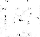
图1A是根据本发明充电器的第一实施例的结构方块图,图1B是表示预定的电池部件被连接至图1A的充电器的状态的方块图,图2是根据本发明充电器的第一实施例和电池部件的外部透视图。所示实施例的充电器1采用插入电源线输出侧的舌簧开关14作为输出切断装置,用于在预定的电池部件2电气上未被连接时切断输出端的输出。1A is a block diagram showing the structure of the first embodiment of the charger according to the present invention, FIG. 1B is a block diagram showing a state in which a predetermined battery unit is connected to the charger of FIG. 1A, and FIG. 2 is a first embodiment of the charger according to the present invention. An external perspective view of an embodiment and battery assembly. The charger 1 of the illustrated embodiment employs a
也就是说,充电器1包括:电池充电控制电路11,它输出充电电流以便对电池组2进行充电;第一输出端子12,它被连接至电池充电控制电路11的正极侧的输出;第二输出端子13,它被连接至电池充电控制电路11的负极侧的输出;以及舌簧开关14,它被串接插入在输出端子12与电池充电控制电路11之间。That is to say, the charger 1 includes: a battery
另一方面,电池部件2是专用于充电器1的第二电池,它包括电池21;正极端子22,它被连接至电池21正极侧;负极端子23,它连接至电池21负极侧;以及使充电器1的舌簧开关14闭合的磁铁(永久磁铁)24。On the other hand, the
在图2中,充电器1在本体的舌簧开关安装部位A上插入舌簧开关14。电池部件在图2所示的磁铁安装部位B上插进磁铁24。舌簧开关14是一种响应磁场强度而被激活的元件。因此,需要确定舌簧开关安装部位A和磁铁安装部位B,以便在电池部件被装入充电器1本体时,磁铁24被放置在紧靠舌簧开关14。In FIG. 2 , the
下面,将对所示充电器1的实施例的操作进行讨论。如图1A中所示,当电池部件2未被装入充电器1的本体时,充电器1的舌簧开关14由于没有经受插在电池部件2中的磁铁24的磁力影响。所以舌簧开关14保持断开状态。结果,即使在电池充电控制电路11输出电压时,充电器1的输出仍然保持断开。In the following, the operation of the illustrated embodiment of the charger 1 will be discussed. As shown in FIG. 1A , when the
当电池部件2被装入充电器1的本体时,如图1B中所示,充电器的输出端子12与电池部件2的正极端子22相连接,与此连带,充电器1的输出端子13与电池部件2的负极端子23相连接。然后,装进充电器1本体的舌簧开关14与装进电池部件2的磁铁24相互紧靠地被放置。这样,当舌簧开关14受到大于或等于预定值的磁力影响的时候,它将被激励为闭合状态。根据这个原理,当电池部件2被装入充电器1中时,舌簧开关14响应磁铁24的磁力变成闭合状态。结果,由于充电器1的输出变成接通(ON),因此充电器1的电池充电控制电路11对安装在电池部件2中的电池21充电。When the
如上所述,通过利用安装在电池部件2中的磁铁24的磁力,激励装在充电器1本体上的舌簧开关14,充电器1的输出仅在装入预定的电池部件2时被接通,而当电池部件2没有被装入时,充电器1的输出被转换为断开(OFF)。As described above, by using the magnetic force of the
(第二实施例)(second embodiment)
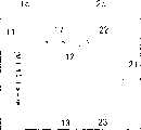
图3A是表示根据本发明充电器的第二实施例的结构方块图,图3B表示预定的电池部件被连接至充电器的状态的方块图,所述的充电器1a的实施例,采用n-沟道MOS场效应晶体管(此后称为FET)15作为插在电源线的输出侧的半导体开关元件,用作输出切断装置,而舌簧开关14a切换FET 15的栅极电压。3A is a block diagram showing the structure of a second embodiment of a charger according to the present invention, and FIG. 3B is a block diagram showing a state in which a predetermined battery component is connected to the charger. The embodiment of the
也就是说,充电器1a输出充电电流,向电池部件2充电。与此相连,充电器1a具有:电池充电控制电路11a,它输出提供给FET 15栅极的“高”电平的电压;第一输出端子12;第二输出端子,它被连接至电池充电控制电路11a的负极侧的输出端;舌簧开关14a,从电池充电控制电路11a来的“高”电平电压输入到它的一端,它的另一端被连接至FET 15的栅极;以及FET 15,它的漏极被连接至电池充电控制电路11a的正极侧的输出端,它的源极和基底被连接至第一输出端子12。类似于第一实施例,充电器1在图2所示的舌簧开关安装位置A上插入舌簧开关14a。电池部件2的结构与第一实施例相同。That is, the
下面,将对所示充电器1a的实施例的操作进行讨论。如图3A所示,当电池部件2未装入充电器1a的本体时,舌簧开关14a由于没有经受安装在电池部件2中的磁铁24的磁力影响,因此它保持在断开状态。结果,由于FET 15转换为截止(OFF),即使电池充电控制电路11a输出电压,充电器1a的输出仍然保持断开(OFF)状态。In the following, the operation of the illustrated embodiment of the
当电池部件2被装入充电器1a的本体时,类似于第一实施例,装在充电器1a的舌簧开关14a与装在电池部件2的磁铁相互紧靠地被放置。这样,舌簧开关14a经受磁体24的磁力影响,成为闭合状态。从电池充电控制电路来的“高”电平电压,通过舌簧开关14a被提供给FET 15的栅极。结果,FET 15的源-漏极变成接通(ON)状态,并且充电器1a的输出变成接通(ON)。所以,电池充电控制电路11a向电池部件2的电池21充电。When the
如上所述,即使在FET 15与舌簧开关14a相组合时,充电器1a的输出只在预定的电池部件2未装入时被转换为接通(ON),而在电池部件2未装入时充电器1a的输出被保持为断开(OFF)。As described above, even when the
(第三实施例)(third embodiment)
图4A是表示根据本发明充电器的第三实施例的结构方块图,图4B表示预定的电池组被连接至充电器的状态的方块图,所述的充电器1b实施例采用插在电源线输出侧的场效应晶体管(FET)15b,霍耳集成电路16,和用于根据霍耳集成电路16的输出,切换FET 15b的栅极电压的电池充电池控制电路11b,它们用作输出切断装置。Fig. 4A is a block diagram showing the structure of the third embodiment of the charger according to the present invention, and Fig. 4B is a block diagram showing a state in which a predetermined battery pack is connected to the charger, and the described
也就是说,充电器1b输出充电电流,并具有:根据霍耳集成电路16的输出用于切换FET 15b的栅极电压的电池充电控制电路11b;第一输出端子12;被连接至电池充电控制电路11b的负极侧的第二输出端子13;FET 15b的漏极被连接至电池充电控制电路11b的正极侧的输出,而源极和基底被连接至第一输出端子12;和霍耳集成电路16。That is, the
充电器1b在第一实施例中所讨论的引导开关安装位置A装有霍耳集成电路16。霍耳集成电路16是一个电子电路部件,它响应被收扰的磁场强度(像舌簧开关那样)而被激活。当不存在磁力时,霍耳集成电路16在所示的实施例中以“高”电平电压输出,当所加的磁力高于或等于预定值时,则输出“低”电平电压。电池组的结构与第一实施例相同。The
下面,将讨论充电器1b的所示实施例的操作。如图4A中所示,当电池部件2未被装入充电器1b的本体中时,充电器1b的霍耳集成电路16不经受装在电池部件2中的磁铁的磁力。所以,输出“高”电平电压输出,电池充电控制电路11b接收这个电压输出,向FET 15b输出“低”电平电压,使FET 15b转换为截止(OFF)状态。因此,即使电池充电控制电路11b输出电压,充电器1b的输出被保持为断开(OFF)状态。Next, the operation of the illustrated embodiment of the
当电池组2被装入充电1b时,装在充电器1b中的霍耳集成电路16和装在电池部件2中的磁铁24彼此贴近。霍耳集成电路16输出“低”电平电压输出。响应这个电压输出,电池充电控制电路11b输出“高”电平电压。结果,FET 15b被转换为导通(ON)状态,使充电器1b处于接通(ON)状态。When the
如上所述,即使在FET 15b和霍耳集成电路16的组合,只有当预定的电池部件2被装入,充电器1b的输出才被转换为接通(ON)状态,而电池部件2未被装入时,充电器1b被维持为断开(OFF)。As described above, even in the combination of the
(第四实施例)(fourth embodiment)
图5A是表示根据本发明充电器的第四实施例的结构方块图,图5B表示预定的二次电池被连接至充电器的状态的方块图,图6是根据本发明充电器的第四实施例和电池组的外部透视图。所示充电器1c的实施例采用机械开关,例如按钮开关,它被插入电源线的输出侧,作为输出切断装置。5A is a block diagram showing the structure of a fourth embodiment of the charger according to the present invention, FIG. 5B is a block diagram showing a state where a predetermined secondary battery is connected to the charger, and FIG. 6 is a fourth embodiment of the charger according to the present invention Example and external perspective view of the battery pack. The illustrated embodiment of the
也就是说,充电器1c包括:电池充电控制电路11;第一输出端子12,它被连接至电池充电控制电路11的正极的输出端;第二输出端子13,它被连接电池充电控制电路11的负极侧的输出端;以及按钮开关17,它被串接插入在输出端子12和电池充电控制电路11之间。That is to say, the
另一方面,电池部件2c具有:电池21;正极端子22,它被连接至电池21的正极侧;以及负极端子23,它被连接至电池21的负极测。On the other hand, the
如图6中所示,在充电器1c的主体上,凹进部分26被提供在与电池部件2c相对的表面上。为了防止错误操作,铵钮开关17被提供在凹进部分26的底部,以使按钮开关17的按键顶部决不会从电池部件1c的主体表面凸出。As shown in FIG. 6, on the main body of the
另一方面,在电池部件2c中,提供有由树脂模制而成的凸出部分25。当被装入充电器1c中时,凸出部分25下压按钮开关17。On the other hand, in the
这里,作为按钮开关17,前提是被按时闭合的ON(正常打开)型开关。电池部件2c的凸出部分25必须是这样的形状,即能与按钮开关17的铵键顶部定位配套,并能充分下压按键顶部。Here, as the
下面,将讨论所示实施例的充电器1c操作。如图5A中所示,电池部件2c未被装入充电器1c的主体中,按钮开关17保持断开状态。结果,即使电池充电控制电路11输出电压,充电器1c的输出仍保持断开(OFF)状态。Next, the operation of the
当电池部件2c被装入充电器1c,凸出部分25与充电器1c的凹进部分相配合时,装在充电器1c中的铵钮开关17被电池部件2c上设置的凸出部分25下压,并因此闭合。结果,充电器1c的输出变成接通(ON)状态。充电器1c的电池充电控制电路11对装在电池部件2c上的电池21充电。When the
如上所述,在这种结构中,机械开关被插在充电器1c的电源线输出侧,所以当预定的电池部件2c被装入时,机械开关被转换为接通(ON)状态。在电池部件2c未被装入的情况下,充电器1c的输出能被保持为断开(OFF)状态。As described above, in this structure, the mechanical switch is inserted on the power cord output side of the
应当注意,在图4中所示的第三实施例中,按钮开关17可被用来代替霍耳集成电路16。也就是说,将按钮开关17的一个触点连接至地,将铵钮开关17的另一端引出接至电池充电控制电路11b,如使用霍耳集成电路16时那样;当电池部件2c未被装入而向电池充电控制电路11b输入“高”电平电压时,按钮开关17被保持为OPEN(断开)。当按钮开关被电池部件2c下压而被置于闭合状态时,“低”电平电压被输入至电池充电控制电路11b。因此,可实现与第三实施例同样的操作。It should be noted that in the third embodiment shown in FIG. 4 , a
就本发明来说,提供有输出切断装置,所以当预定的二次电池未被装入时,输出端子与电池充电控制装置之间的连接被切断,使输出断开,当预定的二次电池被装入时,输出端子和电池充电控制装置被连接,使输出为接通。因此,即使在二次电池未被装入的情况下暴露的输出端子被金属或类似物短路,也能防止充电器发热或元件损坏,从而提高了安全性。另一方面,即使不同于专用的二次电池电池被拿来充电时,输出变成断开。所以,决不会发生专用的二次电池以外的二次电池的错误充电,从而避免充电器损坏或电池液体泄漏。With the present invention, output cutoff means is provided, so when a predetermined secondary battery is not loaded, the connection between the output terminal and the battery charge control means is cut off to disconnect the output, and when the predetermined secondary battery When loaded, the output terminal and the battery charging control device are connected, and the output is turned on. Therefore, even if the exposed output terminal is short-circuited by metal or the like when the secondary battery is not loaded, the charger can be prevented from heating or element damage, thereby improving safety. On the other hand, even when a battery other than a dedicated secondary battery is used for charging, the output becomes off. Therefore, erroneous charging of secondary batteries other than the dedicated secondary battery never occurs, thereby avoiding damage to the charger or leakage of battery liquid.
虽然本发明已就它的范型实施例被作了图示和描述,技术人员应当懂得:在不偏离本发明的精神和范围的情况下,上述和各种其他修改、删除和增添都可在其中做成。因此,本发明不应该被理解为局限于上面描述的特定实施例,而是包括能在所附权利要求中所作的进一步陈述的范围和等效的范围内被具体实现的所有可能的实施例。Although the invention has been illustrated and described with respect to its exemplary embodiments, it should be understood by those skilled in the art that the above and various other modifications, deletions and additions can be made without departing from the spirit and scope of the invention. Which is made. Accordingly, the present invention should not be construed as being limited to the specific embodiments described above, but to include all possible embodiments that can be embodied within the scope and equivalents of the further statements made in the appended claims.
Claims (9)
Translated fromChineseApplications Claiming Priority (2)
| Application Number | Priority Date | Filing Date | Title |
|---|---|---|---|
| JP2000386828 | 2000-12-20 | ||
| JP2000386828AJP2002191129A (en) | 2000-12-20 | 2000-12-20 | Battery charger |
Publications (2)
| Publication Number | Publication Date |
|---|---|
| CN1360384A CN1360384A (en) | 2002-07-24 |
| CN1236539Ctrue CN1236539C (en) | 2006-01-11 |
Family
ID=18853869
Family Applications (1)
| Application Number | Title | Priority Date | Filing Date |
|---|---|---|---|
| CNB011445467AExpired - Fee RelatedCN1236539C (en) | 2000-12-20 | 2001-12-19 | Charger |
Country Status (5)
| Country | Link |
|---|---|
| US (1) | US6534951B2 (en) |
| JP (1) | JP2002191129A (en) |
| CN (1) | CN1236539C (en) |
| GB (1) | GB2374473B (en) |
| HK (1) | HK1049925B (en) |
Families Citing this family (36)
| Publication number | Priority date | Publication date | Assignee | Title |
|---|---|---|---|---|
| US6969928B2 (en)* | 2002-05-31 | 2005-11-29 | Lsi Logic Corporation | Magnetic proximity interface control |
| KR20020086445A (en)* | 2002-10-26 | 2002-11-18 | 유병섭 | Structure of electric contact between two devices |
| ATE451731T1 (en)* | 2003-04-29 | 2009-12-15 | 3M Espe Ag | PREVENTING ELECTROCHEMICAL CORROSION ON THE CHARGING CONTACTS OF A BATTERY POWERED HANDPIECE AND ITS CHARGER |
| ATE538525T1 (en)* | 2004-01-20 | 2012-01-15 | Campagnolo Srl | RECHARGEABLE POWER SUPPLY UNIT FOR A BICYCLE |
| JP4786881B2 (en)* | 2004-06-10 | 2011-10-05 | 旭化成エレクトロニクス株式会社 | Vacuum cleaner and iron |
| KR20060014750A (en)* | 2004-08-12 | 2006-02-16 | 엘지전자 주식회사 | Battery Chargers for Mobile Terminals |
| JP4877455B2 (en)* | 2005-03-28 | 2012-02-15 | ミツミ電機株式会社 | Secondary battery protection module and lead mounting method |
| EP2993726B1 (en)* | 2005-11-07 | 2017-04-26 | Vital Signs, Inc. | Lithium polymer battery powered intravenous fluid warmer |
| US20070114969A1 (en)* | 2005-11-22 | 2007-05-24 | Koninklijke Philips Electronic, N.V. | Magnetic electrical daisy connection for simultaneously recharging electronic devices |
| US7816886B2 (en) | 2006-03-08 | 2010-10-19 | Eveready Battery Company, Inc. | Battery charger |
| US8169196B2 (en)* | 2007-06-27 | 2012-05-01 | Sony Mobile Communications Ab | Charging device |
| US7671559B2 (en)* | 2007-07-31 | 2010-03-02 | Apple Inc. | Battery charging system and mobile and accessory devices |
| US20090035609A1 (en)* | 2007-07-31 | 2009-02-05 | Apple Inc. | Intelligent universal rechargeable batteries for battery charging system for mobile and accessory devices |
| JP5549184B2 (en) | 2009-10-29 | 2014-07-16 | 日立工機株式会社 | Charger |
| US9103578B2 (en)* | 2009-12-21 | 2015-08-11 | Whirlpool Corporation | Substance communicating device for coupling to a host |
| US20110148649A1 (en)* | 2009-12-21 | 2011-06-23 | Whirlpool Corporation | Proximity Sensor Enabled Electromagnetic Service Connector System |
| US8517337B2 (en)* | 2009-12-21 | 2013-08-27 | Whirlpool Corporation | Proximity sensor enabled substance communication coupling system |
| US8430221B2 (en)* | 2009-12-21 | 2013-04-30 | Whirlpool Corporation | Mechanically energized mechanical power coupling system |
| US8342480B2 (en)* | 2009-12-21 | 2013-01-01 | Whirlpool Corporation | Substance communicating device with mechanically energized connector |
| US8439178B2 (en)* | 2009-12-21 | 2013-05-14 | Whirlpool Corporation | Proximity sensor enabled mechanical power coupling system |
| US8405253B2 (en)* | 2009-12-21 | 2013-03-26 | Whirlpool Corporation | Mechanically energized eService connector system |
| US8528610B2 (en)* | 2009-12-21 | 2013-09-10 | Whirlpool Corporation | Mechanically energized substance communication coupling system |
| US20110148651A1 (en)* | 2009-12-21 | 2011-06-23 | Whirlpool Corporation | Substance Communicating Device with Sensor Enabled Connector |
| US8830660B2 (en)* | 2009-12-21 | 2014-09-09 | Whirlpool Corporation | Mechanical power service communicating device and system |
| US20110153739A1 (en)* | 2009-12-21 | 2011-06-23 | Whirlpool Corporation | Proximity Sensor Enabled eService Connector System |
| US8382065B2 (en)* | 2009-12-21 | 2013-02-26 | Whirlpool Corporation | Substance communicating device with mechanically energized connector system |
| US8745203B2 (en)* | 2009-12-21 | 2014-06-03 | Whirlpool Corporation | Mechanical proximity sensor enabled eService connector system |
| US8700809B2 (en)* | 2009-12-21 | 2014-04-15 | Whirlpool Corporation | Substance communicating device with activatable connector and cycle structure |
| US8387948B2 (en)* | 2009-12-21 | 2013-03-05 | Whirlpool Corporation | Mechanically energized substance communication coupling system |
| US20110148650A1 (en)* | 2009-12-21 | 2011-06-23 | Whirlpool Corporation | Mechanical Proximity Sensor Enabled Electromagnetic Service Connector System |
| WO2013054164A2 (en)* | 2011-09-23 | 2013-04-18 | Sa Shuang | Battery device providing uninterrupted power and electronic devices having said battery device |
| US9146207B2 (en) | 2012-01-10 | 2015-09-29 | Hzo, Inc. | Methods, apparatuses and systems for sensing exposure of electronic devices to moisture |
| AU2013208273B2 (en) | 2012-01-10 | 2015-11-26 | Hzo, Inc. | Methods, apparatuses and systems for monitoring for exposure of electronic devices to moisture and reacting to exposure of electronic devices to moisture |
| KR101560114B1 (en) | 2013-01-08 | 2015-10-13 | 에이치제트오 인코포레이티드 | Apparatuses, systems, and methods for detecting and reacting to exposure of an electronic device to moisture |
| US9563244B2 (en)* | 2013-01-08 | 2017-02-07 | Hzo, Inc. | Apparatuses, systems, and methods for reducing power to ports of electronic devices |
| CN104578231B (en)* | 2013-10-12 | 2017-12-01 | 苏州宝时得电动工具有限公司 | Charger and charging system |
Family Cites Families (7)
| Publication number | Priority date | Publication date | Assignee | Title |
|---|---|---|---|---|
| GB2200804A (en)* | 1987-01-28 | 1988-08-10 | Combined Optical Ind Ltd | Alternative electrical power source system |
| JPH0380641U (en)* | 1989-12-04 | 1991-08-19 | ||
| JPH08182206A (en)* | 1994-12-26 | 1996-07-12 | Yamaha Motor Co Ltd | Safety device of battery charger |
| GB2346274B (en)* | 1995-10-31 | 2000-09-20 | Motorola Inc | Apparatus and method for discharging and charging a multiple battery arrangement |
| US5734254A (en)* | 1996-12-06 | 1998-03-31 | Hewlett-Packard Company | Battery pack and charging system for a portable electronic device |
| JP3133031B2 (en)* | 1998-09-01 | 2001-02-05 | 三菱電機株式会社 | Battery charging system and information processing device |
| US6204632B1 (en)* | 1999-09-08 | 2001-03-20 | Selfcharge | Apparatus for charging multiple batteries |
- 2000
- 2000-12-20JPJP2000386828Apatent/JP2002191129A/enactivePending
- 2001
- 2001-12-19CNCNB011445467Apatent/CN1236539C/ennot_activeExpired - Fee Related
- 2001-12-19USUS10/025,034patent/US6534951B2/ennot_activeExpired - Fee Related
- 2001-12-20GBGB0130522Apatent/GB2374473B/ennot_activeExpired - Fee Related
- 2003
- 2003-03-24HKHK03102112.6Apatent/HK1049925B/ennot_activeIP Right Cessation
Also Published As
| Publication number | Publication date |
|---|---|
| CN1360384A (en) | 2002-07-24 |
| JP2002191129A (en) | 2002-07-05 |
| US20020074970A1 (en) | 2002-06-20 |
| GB2374473A (en) | 2002-10-16 |
| GB0130522D0 (en) | 2002-02-06 |
| HK1049925B (en) | 2005-01-21 |
| HK1049925A1 (en) | 2003-05-30 |
| GB2374473B (en) | 2004-08-18 |
| US6534951B2 (en) | 2003-03-18 |
Similar Documents
| Publication | Publication Date | Title |
|---|---|---|
| CN1236539C (en) | Charger | |
| CN101814725B (en) | Secondary battery | |
| EP0918389A2 (en) | Low loss reverse battery protection | |
| CN110474289A (en) | A kind of load short-circuit protection circuit | |
| RU2003122780A (en) | AUXILIARY BATTERY FOR CELL PHONE | |
| CN1591964A (en) | Battery charger | |
| US20240113514A1 (en) | Protection circuit for battery management system | |
| JP2003203721A (en) | DC outlet | |
| KR100462465B1 (en) | A charging battery case having uni-jack, and a jack plug for the case | |
| CN111933486A (en) | Relay surge current protection circuit and charging circuit | |
| CN1758063A (en) | Apparatus and method for detecting a short of a battery connector | |
| CN1571277A (en) | Novel electronic circuit waterproof device | |
| CN1300890C (en) | Built-in cell controller for personal communicater | |
| CN111490570B (en) | Protection circuits and electronic equipment | |
| TWI731583B (en) | Semiconductor device and charging system using the same | |
| CN114614216B (en) | Secondary batteries and battery modules | |
| JP3341227B2 (en) | Battery terminal short circuit prevention device | |
| CN2667763Y (en) | Electronic waterproof protective plate | |
| CN2687902Y (en) | Power supply connector | |
| CN219610911U (en) | Insertion detection module and socket | |
| CN218099412U (en) | Insertion detection circuit and energy storage inverter | |
| CN1292526C (en) | Charger and electric device | |
| CN114498791B (en) | Electrical path management circuit, electrical path management chip and electronic equipment | |
| US20240178836A1 (en) | Semiconductor device, electronic apparatus and vehicle | |
| CN214590645U (en) | Electric motor car charging port anticreep circuit and electric motor car |
Legal Events
| Date | Code | Title | Description |
|---|---|---|---|
| C10 | Entry into substantive examination | ||
| SE01 | Entry into force of request for substantive examination | ||
| C06 | Publication | ||
| PB01 | Publication | ||
| C14 | Grant of patent or utility model | ||
| GR01 | Patent grant | ||
| C17 | Cessation of patent right | ||
| CF01 | Termination of patent right due to non-payment of annual fee | Granted publication date:20060111 Termination date:20101219 |