CN1229248C - bicycle saddle - Google Patents
bicycle saddleDownload PDFInfo
- Publication number
- CN1229248C CN1229248CCNB031082181ACN03108218ACN1229248CCN 1229248 CCN1229248 CCN 1229248CCN B031082181 ACNB031082181 ACN B031082181ACN 03108218 ACN03108218 ACN 03108218ACN 1229248 CCN1229248 CCN 1229248C
- Authority
- CN
- China
- Prior art keywords
- saddle
- bicycle
- knee
- rider
- present
- Prior art date
- Legal status (The legal status is an assumption and is not a legal conclusion. Google has not performed a legal analysis and makes no representation as to the accuracy of the status listed.)
- Expired - Fee Related
Links
Images


Classifications
- B—PERFORMING OPERATIONS; TRANSPORTING
- B62—LAND VEHICLES FOR TRAVELLING OTHERWISE THAN ON RAILS
- B62J—CYCLE SADDLES OR SEATS; AUXILIARY DEVICES OR ACCESSORIES SPECIALLY ADAPTED TO CYCLES AND NOT OTHERWISE PROVIDED FOR, e.g. ARTICLE CARRIERS OR CYCLE PROTECTORS
- B62J1/00—Saddles or other seats for cycles; Arrangement thereof; Component parts
- B62J1/28—Other additional equipment, e.g. back-rests for children
- B—PERFORMING OPERATIONS; TRANSPORTING
- B62—LAND VEHICLES FOR TRAVELLING OTHERWISE THAN ON RAILS
- B62J—CYCLE SADDLES OR SEATS; AUXILIARY DEVICES OR ACCESSORIES SPECIALLY ADAPTED TO CYCLES AND NOT OTHERWISE PROVIDED FOR, e.g. ARTICLE CARRIERS OR CYCLE PROTECTORS
- B62J1/00—Saddles or other seats for cycles; Arrangement thereof; Component parts
- B—PERFORMING OPERATIONS; TRANSPORTING
- B62—LAND VEHICLES FOR TRAVELLING OTHERWISE THAN ON RAILS
- B62J—CYCLE SADDLES OR SEATS; AUXILIARY DEVICES OR ACCESSORIES SPECIALLY ADAPTED TO CYCLES AND NOT OTHERWISE PROVIDED FOR, e.g. ARTICLE CARRIERS OR CYCLE PROTECTORS
- B62J25/00—Foot-rests; Knee grips; Passenger hand-grips
- B62J25/02—Knee grips, e.g. on fuel tanks
Landscapes
- Engineering & Computer Science (AREA)
- Mechanical Engineering (AREA)
- Automatic Cycles, And Cycles In General (AREA)
Abstract
Description
Translated fromChinese技术领域technical field
本发明涉及一种用于提高车体的稳定性的自行车用鞍座及自行车用骑车者支承构造。The present invention relates to a saddle for a bicycle and a rider support structure for a bicycle for improving the stability of a vehicle body.
背景技术Background technique
作为自行车用鞍座,公知的有例如记载于①日本特开平5-147563号公报“自行车用鞍座”、②日本特开平8-281508号公报“自行车用车架”中的形式的自行车用鞍座。As bicycle saddles, for example, those described in ① Japanese Patent Application Laid-Open No. 5-147563 "Saddle for Bicycle" and ② Japanese Patent Laid-Open No. 8-281508 "Bicycle Frame" are known. seat.
在上述①的图3中记载着由表皮构件20(符号使用该公报所记载的符号。以下相同。)覆盖表面的鞍座1。In FIG. 3 of the above-mentioned ①, the saddle 1 whose surface is covered with the skin member 20 (the symbols described in this publication are used. The same applies hereinafter.) is described.
在上述②的图3中记载着鞍座的侧面。The side surface of the saddle is described in Fig. 3 of the above-mentioned ②.
例如,在用于行走在下坡路上竞争时间的下坡等的比赛的自行车中,根据道路的状态需要从鞍座上浮起腰来保持车体的稳定性。在这样的情况下,骑车者除了车把和踏板的支承之外,如果还用身体支承鞍座,则可有效地使车体保持稳定,而且还可以良好地保持骑车者的姿势。例如,将鞍座夹在大腿的内侧、或将移动到鞍座之前的骑车者的腰部接触并支承于鞍座的前部。For example, in a bicycle used for races such as downhill running on a downhill road to compete for time, it is necessary to maintain the stability of the vehicle body by lifting the waist from the saddle depending on the state of the road. In such a case, if the rider supports the saddle with his/her body in addition to the support of the handlebars and pedals, the vehicle body can be effectively stabilized and the rider's posture can be maintained well. For example, the saddle is clamped on the inner side of the thigh, or the waist of the rider before the saddle is brought into contact with and supported on the front portion of the saddle.
在上述①的鞍座1中,即使想要以从鞍座1浮起腰的状态进行支承也难以以大腿的内侧的所希望的位置进行支承,而且,即使支承腰部,由于鞍座1的前部为凸形状,因此施加在腰部上的压力高,不好。而且,而且也没有采用特别的用于保持骑车者姿势的构造。In the above-mentioned saddle 1 of ①, it is difficult to support the inner side of the thigh at a desired position even if it is intended to support the waist from the saddle 1, and even if the waist is supported, the front of the saddle 1 cannot The waist is convex, so the pressure on the waist is high, which is not good. Furthermore, no special structure for maintaining the rider's posture is adopted.
对于上述②的鞍座,情况也相同。The same applies to the saddle of ② above.
这样的骑车者支承的部分如果可以使车体稳定,则不限定于鞍座自身,也可以是鞍近旁的部分、即骑车者在从鞍座浮起腰的状态下由大腿的内侧夹着的、或顶着腰部的车体部分,也可以根据骑车者的体格、自行车的规格等设置其部分。If the part supported by such a rider can stabilize the vehicle body, it is not limited to the saddle itself, and may be a part near the saddle, that is, the rider is clamped by the inner side of the thigh when the rider is floating from the saddle. The part of the vehicle body that rests on or against the waist can also be provided according to the rider's physique, the specifications of the bicycle, and the like.
发明内容Contents of the invention
因此,本发明的目的在于通过改进自行车用鞍座及自行车用骑车者支承构造来提高车体的稳定性,良好地保持骑车者的姿势。Therefore, an object of the present invention is to improve the stability of the vehicle body and maintain the rider's posture well by improving the bicycle saddle and the bicycle rider support structure.
为了达到上述目的,本发明的第一技术方案的自行车用鞍座,其特征在于,使骑车者坐的座面的两侧面向后方伸出,并且使该伸出部侧面也向下方伸出,由此形成左右一对膝夹紧部,骑车者用膝的内侧、大腿的内侧夹这些膝夹紧部。In order to achieve the above object, the bicycle saddle according to the first technical solution of the present invention is characterized in that both sides of the seat surface on which the rider sits protrude rearward, and the side surfaces of the protruding part also protrude downward. , thereby forming a pair of left and right knee clamping parts, and the rider clamps these knee clamping parts with the inner side of the knee and the inner side of the thigh.
自行车在行驶中,骑车者可以支承自行车的车把、踏板及膝夹紧部,可以提高自行车的稳定性,并且可以良好地保持骑车者的姿势。When the bicycle is running, the rider can support the handlebar, the pedal and the knee clamping part of the bicycle, the stability of the bicycle can be improved, and the posture of the rider can be kept well.
本发明的第二技术方案的自行车用鞍座,其特征在于,将膝夹紧部与座面成形为一体。A bicycle saddle according to a second aspect of the present invention is characterized in that the knee clamp portion is formed integrally with the seat surface.
由此,可以减少鞍座的零件数量,可以降低鞍座的成本。另外,可以容易地制造一体地成形有膝夹紧部的鞍座。Thereby, the number of parts of the saddle can be reduced, and the cost of the saddle can be reduced. In addition, the saddle integrally formed with the knee grip can be easily manufactured.
本发明的第三技术方案的自行车用鞍座,其特征在于,相对于具有座面的鞍座本体另成一体地构成膝夹紧部。A bicycle saddle according to a third aspect of the present invention is characterized in that the knee clamp portion is formed integrally with the saddle body having the seat surface.
由此,可以根据需要卸下膝夹紧部,可以提高使用方便性。而且,可以在现有的只由座面构成的鞍座上安装膝夹紧部。Thereby, the knee clamp part can be detached as needed, and usability can be improved. Furthermore, the knee clamping part can be installed on the existing saddle composed of only the seat surface.
本发明的第四技术方案的自行车用鞍座,其特征在于,通过在座面的后部安装板构件,由该板构件兼用作覆盖后轮的上方的后挡泥板和骑车者用膝的内侧、大腿的内侧夹的膝夹紧部,该板部形成有向车体后方延伸的后部延伸出部和从该后部延伸出部的前部两侧部向下方延伸的左右一对的下方伸出部。The bicycle saddle according to the fourth aspect of the present invention is characterized in that, by attaching a plate member to the rear portion of the seat surface, the plate member doubles as a rear fender covering the upper part of the rear wheel and as a seat for the rider's knees. The inner side, the knee clamping part of the inner side of the thigh, the plate part is formed with a rear extension part extending to the rear of the vehicle body and a pair of left and right sides extending downward from the front side parts of the rear extension part. Bottom extension.
除了由膝夹紧部带来车体的稳定化之外,还可以防止后轮的溅泥或飞起的石头等。In addition to the stability of the car body brought about by the knee clamp, it can also prevent the rear wheels from splashing mud or flying stones.
本发明的第五技术方案的自行车用鞍座,其特征在于,通过设置从座面的前端向下方或前斜下方延伸的延伸出部,在骑车者采取将臀部从座面向车体前方移动了的姿势时,用延伸出部的前面承受臀部或腰部。The bicycle saddle according to the fifth aspect of the present invention is characterized in that by providing an extending portion extending downward or obliquely downward from the front end of the seat surface, when the rider moves the buttocks from the seat surface to the front of the vehicle body, In the upright position, use the front of the extended part to support the buttocks or waist.
在骑车者采用将臀部从座面向车体前方移动了的姿势时,通过用延伸出部的前面承受臀部或腰部,可以使臀部或腰部与延伸出部的前面面接触,可以防止对臀部或腰部作用大的压力。When the rider adopts a posture that moves the buttocks from the seat to the front of the vehicle body, by receiving the buttocks or the waist from the front of the extension part, the buttocks or waist can be brought into contact with the front surface of the extension part, and it is possible to prevent damage to the buttocks or the waist. The lower back exerts a lot of pressure.
本发明的第六技术方案的自行车用鞍座,其特征在于,与座面一体成形延伸出部。A sixth aspect of the present invention is a bicycle saddle characterized in that the extending portion is formed integrally with the seat surface.
由此可以减少鞍座的零件数量,可以降低鞍座的成本。而且可以容易地制造一体成形着延伸出部的鞍座。Thereby, the number of parts of the saddle can be reduced, and the cost of the saddle can be reduced. Also, the saddle with the extended portion integrally formed can be easily manufactured.
本发明的第七技术方案的自行车用鞍座,其特征在于,通过支承构件将延伸出部安装在具有座面的鞍座本体上,相对于鞍座本体另成一体地构成延伸出部。A bicycle saddle according to a seventh aspect of the present invention is characterized in that the extension portion is attached to a saddle body having a seat surface via a support member, and the extension portion is formed integrally with the saddle body.
可以根据需要卸下延伸出部,可以提高使用方便性。The extension part can be detached as needed, which can improve the convenience of use.
本发明的第八技术方案的自行车用鞍座,其特征在于,将支承构件做成为固定于鞍座本体上的底板上的撑条。A bicycle saddle according to an eighth aspect of the present invention is characterized in that the supporting member is a stay fixed to a bottom plate of the saddle body.
如果变更撑条的形状,则可以变更延伸出部的位置,可以根据骑车者的喜好配置延伸出部。If the shape of the stay is changed, the position of the extending portion can be changed, and the extending portion can be arranged according to the preference of the rider.
本发明的第九技术方案的自行车用鞍座,其特征在于,支承构件是使设置在鞍座本体的底部上的底板延伸出而形成的。According to a ninth aspect of the present invention, the bicycle saddle is characterized in that the supporting member is formed by extending a bottom plate provided on the bottom of the saddle body.
由此,可以减少鞍座的零件数量,可以降低鞍座的成本。Thereby, the number of parts of the saddle can be reduced, and the cost of the saddle can be reduced.
本发明的第十技术方案的自行车用骑车者支承构造,其特征在于,通过在鞍座的前端的前方且下方的车架上设置向上方或后斜上方延伸的延伸片,在骑车者采取将臀部从座面向车体前方移动了的姿势时,由延伸片的前面承承臀部或腰部。The rider support structure for a bicycle according to the tenth technical solution of the present invention is characterized in that an extension piece extending upward or obliquely upward behind the front end of the saddle is provided on the frame in front of and below the front end of the saddle, so that the rider's When the buttocks are moved from the seat to the front of the vehicle body, the buttocks or the waist are supported by the front surface of the extension piece.
通过在车架上设置伸出片,在骑车者采取将臀部从座面向车体前方移动了的姿势时,由伸出片的前面承受臀部或腰部,由此,可以使臀部或腰部与延伸片的前面面接触,可以防止对臀部或腰部作用大地压力。By providing the protruding piece on the frame, when the rider takes the posture of moving the buttocks from the seat to the front of the vehicle body, the front of the protruding piece bears the buttocks or the waist, thereby, the buttocks or the waist can be aligned with the extending piece. The front face contact prevents ground pressure on the hips or lower back.
附图说明Description of drawings
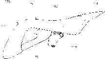
图1是具有本发明的鞍座(第一实施例)的自行车的立体图。Fig. 1 is a perspective view of a bicycle having a saddle (first embodiment) of the present invention.
图2是具有本发明的鞍座(第一实施例)的自行车的侧视图。Fig. 2 is a side view of a bicycle having a saddle (first embodiment) of the present invention.
图3是本发明的鞍座(第一实施例)的侧视图。Fig. 3 is a side view of the saddle (first embodiment) of the present invention.
图4是图3的4向视图。Fig. 4 is a 4-direction view of Fig. 3 .
图5是图3的5-5剖面图。Fig. 5 is a cross-sectional view along line 5-5 of Fig. 3 .
图6是表示本发明的鞍座(第一实施例)的作用的作用图。Fig. 6 is an action diagram showing the action of the saddle (first embodiment) of the present invention.
图7是本发明的鞍座(第二实施例)的侧视图。Fig. 7 is a side view of a saddle (second embodiment) of the present invention.
图8是图7的8向视图。Fig. 8 is an 8-direction view of Fig. 7 .
图9是本发明的鞍座(第二实施例)的剖面图。Fig. 9 is a sectional view of a saddle (second embodiment) of the present invention.
图10是本发明的鞍座(第三实施例)的侧视图。Fig. 10 is a side view of a saddle (third embodiment) of the present invention.
图11是本发明的鞍座(第四实施例)的侧视图。Fig. 11 is a side view of a saddle (fourth embodiment) of the present invention.
图12是本发明的鞍座(第四实施例)的延伸出部的剖面图。Fig. 12 is a cross-sectional view of an extended portion of a saddle (fourth embodiment) of the present invention.
图13是图11的13-13剖面图。Fig. 13 is a sectional view taken along line 13-13 of Fig. 11 .
图14是表示本发明的鞍座(第四实施例)的作用的作用图。Fig. 14 is an action diagram showing the action of the saddle (fourth embodiment) of the present invention.
图15是本发明的鞍座(第五实施例)的侧视图。Fig. 15 is a side view of a saddle (fifth embodiment) of the present invention.
图16是本发明的鞍座(第五实施例)的前部的剖面图。Fig. 16 is a sectional view of the front portion of the saddle (fifth embodiment) of the present invention.
图17是表示本发明的鞍座的另外的实施例(第六实施例)的剖面图。Fig. 17 is a sectional view showing another embodiment (sixth embodiment) of the saddle of the present invention.
图18是表示本发明的自行车用骑车者支承构造(第七实施例)的侧视图。Fig. 18 is a side view showing a rider support structure for a bicycle (seventh embodiment) of the present invention.
图19是本发明的鞍座(第八实施例)的侧视图。Fig. 19 is a side view of a saddle (eighth embodiment) of the present invention.
图20是本发明的鞍座(第八实施例)的立体图。Fig. 20 is a perspective view of a saddle (eighth embodiment) of the present invention.
图21是本发明的鞍座(第八实施例)的俯视图。Fig. 21 is a plan view of a saddle (eighth embodiment) of the present invention.
图22是图21的22-22剖面图。Fig. 22 is a sectional view taken along line 22-22 of Fig. 21 .
具体实施方式Detailed ways
以下,根据附图说明本发明的实施例。附图是沿符号的朝向看到的图。Hereinafter, embodiments of the present invention will be described with reference to the drawings. The drawings are diagrams viewed along the direction of the symbols.
图1是具有本发明的鞍座(第一实施例)的自行车的立体图。自行车10是下坡用的自行车,因为使用于通过沿在林间道路、滑雪场等设置有高速道路或跳越区域的未铺筑的道路下坡进行时间竞争的比赛,在前轮11及后轮12上分别由前叉14和后缓冲单元15吸收来自路面的冲击,在车架16处,通过提高刚性支承大的负荷,另一方面使车架16的一部分具有柔韧性来提高操纵性,而且,为了提高前轮11及后轮12的制动力而采用了盘式制动器(在以后详细叙述)。Fig. 1 is a perspective view of a bicycle having a saddle (first embodiment) of the present invention.
图2是具有本发明的鞍座(第一实施例)的自行车的侧视图,自行车10在头管21上可操纵方向地安装着上述的前叉14,在该前叉14的下端可旋转地安装着前轮11,在前叉14的上部安装着操纵手柄22,从头管21向后斜下方伸出车架16,在该车架16的后部上下可摆动地安装着L字状的摆臂23,在该摆臂23的后端可旋转地安装着后轮12,在车架16与摆臂23上架设着后缓冲单元15,在车架16的后部安装着变速机25,在该变速机25的左右分别安装着踏板26、27,在车架16的中间部安装着鞍座28。2 is a side view of a bicycle with a saddle (first embodiment) of the present invention. The
在此,31是前轮用盘式制动器(32是制动器卡钳,33是制动盘),34、34(里侧的符号34未图示)是保护前叉14的下部的前叉保护器,35是前挡泥板,36是由软管连接在后缓冲单元15上的副油箱,38是安装在变速机25的输出轴上的驱动侧链轮,41是安装在后轮12上的从动侧链轮,42是架设在驱动侧链轮38与从动侧链轮41上的链,43是后轮用盘式制动器(44是制动器卡钳,45是制动器盘)。Here, 31 is a disc brake for a front wheel (32 is a brake caliper, 33 is a brake disc), 34, 34 (
车架16由箱状的箱状构架部51、双管部52、后部构架部53、下伸管54、鞍座支架56(参照图2)构成,该箱状构架部51从头管21向后斜下方延伸,该双管部52从该箱状构架部51的后端向左右分开并向后斜下方、即在箱状构架部51的延长线上延伸,该后部构架部53从该双管部52的后端使其比箱状构架部51及双管部52的倾斜角更倾斜地向后斜下方延伸,该下伸管54从箱状构架部51的前端下部向后斜下方延伸,并且与后部构架部53的后端连接,该鞍座支架56是用于将鞍座28(参照图2)安装到双管部52的后端及后部构架部53的中间部。The
箱状构架部51是通过形成为箱状来使车架16的前部具有高刚性的部分。The box-shaped
双管部52是通过分为左右管52L、52R(参照图1)来降低刚性而使车架16的中央部容易扭曲的部分,在后端内面上具有安装后缓冲单元15(参照图2)的前面的缓冲器安装部(未图示),在后端上部具有用于安装鞍座56的前部的鞍座前部安装部52B、52B(里侧的鞍座构架安装部52B未图示。同时参照图1)。The
后部构架部53是通过加大左右宽度而容易收纳变速机25、并提高了支持作用于摆臂23的安装部的扭曲的支承力的部分,由左右的构架部53L、53R(里侧的构架部53R未图示)构成,具有用于在中间部内面上安装摆臂23的前端的臂安装部(未图示)。具有用于将鞍座支架56的后部安装在中间部上部的鞍座支架后部安装部53C、53C(里侧的鞍座支架后部安装部53C未图示)。The
下伸管54具有两股叉部54A和变速机安装孔54B、54B(里侧的变速机安装孔54B未图示),该两股叉部54A为了在其后部支承变速机25、并且连接在后部构架部53的后端上而形成为两股叉状,上述变速机安装孔54B、54B是为了在上述两股叉部54A的根部分上安装变速机25而开设的。54C、54C(里侧的符号54C未图示)是构成两股叉部54A的左右的弯曲状臂部。The
如上所述,在头管21的附近形成为高刚性的箱状构架部51,在该箱状构架部51的后方构成为低刚性的双管部52,由此,在箱状构架部51处承受住从前轮11通过前叉14传递到车架16上的大负荷,使从双管部52起的后方的车架16产生扭曲而防止上述大负荷的急剧的传递,从而同时实现提高车架16的刚性和提高车辆的操纵性。As described above, a highly rigid box-shaped
摆臂23是大致L字状的构件,该摆臂23由从安装在后部构架部53上的枢轴61向后斜上方延伸的立起部62和从该立起部62的上端向后斜下方延伸的后部延伸出部构成。在立起部62和后部延伸出部的连接部安装着后缓冲单元15的后端的安装轴64。65是设置在双管部52上的安装轴,它用于安装后缓冲单元15的前端,67是后轮12的车轴。The
图3是本发明的鞍座(第一实施例)的侧视图,通过使鞍座28的座面71的两侧面72、73(里侧的侧面73未图示)向后方伸出并也向下方伸出,而形成骑车者用膝的内侧、大腿的内侧夹的左右一对膝夹紧部74、75(里侧的膝夹紧部75未图示。膝夹紧部74是施加了剖面线的部分。在本实施例中以下都相同。)。74A,75A是膝夹紧部74、75的伸出侧面。另外,图中的双点划线表示现有的鞍座的后部形状(以下相同)。Fig. 3 is a side view of the saddle (first embodiment) of the present invention, by making the two sides 72, 73 of the
图4是图3的4向示图,表示使膝夹紧部74、75从鞍座28的两侧部向后方凸出的情况。即,使膝夹紧部74、75相对于鞍座28的后部中央部77向后方凸出。FIG. 4 is a 4-direction view of FIG. 3 , showing a state in which the
图5是图3的5-5剖面图,表示使膝夹紧部74、75从鞍座28的两侧部向下方凸出的情况。即,分别使设置在鞍座28的底部的底板78的侧壁81、81比原来向下方延长,在该侧壁81、81的侧部也配置缓冲件82,将该缓冲件82由表皮件83覆盖。FIG. 5 is a cross-sectional view taken along line 5-5 of FIG. 3 , showing a state in which the
以下说明以上所述的鞍座28的作用。The function of the above-mentioned
图6是表示本发明的鞍座(第一实施例)的作用的作用图。Fig. 6 is an action diagram showing the action of the saddle (first embodiment) of the present invention.
例如,在下坡等的比赛中,当路面的凸凹大时,因为车体不稳定,骑车者85使腰从鞍座28浮起,由大腿的内侧夹膝夹紧部74、75,由此可以由操纵手柄22、踏板26、27以及膝夹紧部74、75三点进行支承,可以使自行车10更加稳定。For example, in a race such as downhill, when the unevenness of the road surface is large, the
如由以上的图3~图5及图6说明的那样,本发明的第一特征是,通过使骑车者85坐的座面71的两侧面72、73向后方伸出,并且使该伸出部侧面74A、75A也向下方伸出,从而形成左右一对膝夹紧部74、75,骑车者85用膝内侧、大腿的内侧夹这些膝夹紧部74、75。As explained by the above FIGS. 3 to 5 and 6, the first feature of the present invention is that by making the two sides 72, 73 of the
在自行车10行驶中,骑车者85可以由操纵手柄22、踏板26、27以及膝夹紧部74、75支承自行车10,可以提高自行车10的稳定性,随之,提高了自行车10的操纵性。另外,在行驶中,骑车者85通过夹膝夹紧部74、75可以良好地保持骑车者85的姿势,例如可提高拐弯速度。When the
而且,若加大膝夹紧部74、75的伸出侧面74A、75A的面积,则可以容易用膝的内侧、大腿的内侧夹膝夹紧部74、75,可以提高使用方便性。Moreover, if the area of the protruding side surfaces 74A, 75A of the
本发明的第二特征是与座面71一体地成形膝夹紧部74、75。由此,可以减少鞍座28的零件数量,可以降低鞍座28的成本。而且,容易制造一体地成形有膝夹紧部74、75的鞍座28。A second feature of the present invention is that the knee grips 74 , 75 are integrally formed with the
图7是本发明的鞍座(第二实施例)的侧视图,它表示的是在鞍座本体86的后部及下部安装了树脂制或轻合金制的膝夹紧部87的鞍座88。作为该实施例,它相当于在现有的鞍座上附加了膝夹紧部87。91是鞍座支架,该鞍座支架91支承设置在鞍座本体86的底部的底板(未图示),并且安装在用鞍座支架56支承的鞍座支柱92上。7 is a side view of a saddle (second embodiment) of the present invention, which shows a
膝夹紧部87具有左右一对的伸出侧面87A、87B(里侧的伸出侧面87B未图示),该左右一对的伸出侧面87A、87B向鞍座本体86的后方伸出并且也向下方伸出。The
图8是图7的8向示图,表示从鞍座本体86的后部两侧部一直到后部配置了膝夹紧部87的情形。FIG. 8 is an 8-direction view of FIG. 7 , showing that the
膝夹紧部87的两侧部向后方凸出而形成后方凸出部87C、87D。在膝夹紧部87中,使后部中央部87E凹陷,但也可以是使后部中央部87E后退到后方伸出部87C、87D而将膝夹紧部87的后部形成为平面状。Both side portions of the
图9(a)、(b)是本发明的鞍座(第二实施例)的剖面图。9( a ), ( b ) are cross-sectional views of a saddle (second embodiment) of the present invention.
(a)是图7的A-A剖面图,在鞍座88的鞍座支架91上安装固定配件94,在该固定配件94上由小螺钉95固定了膝夹紧部87。97、98是用于将固定配件94安装在鞍座支架91上的小螺钉和螺母,101是用于将小螺钉95连接在固定配件94上的螺母,102是用于阻止小螺钉91旋转的锁定螺母。(a) is a sectional view of A-A of Fig. 7, on the
(b)是图7的B-B剖面图,表示的是,在鞍座88的底板105上由小螺钉106安装着作为支承构件的撑条107,在该撑条107上用小螺钉108及螺母111安装了膝夹紧部87。112是为了与小螺钉106螺纹结合而一体地设在底板105上的螺母。(b) is the B-B sectional view of Fig. 7, shows that, on the base plate 105 of
如以上的用图7说明的那样,本发明的第三特征在于相对于具有座面71的鞍座本体86另成一体地构成膝夹紧部87。As described above with reference to FIG. 7 , the third feature of the present invention is that the
根据需要可以从鞍座本体86上卸下膝夹紧部87,可以使鞍座88的使用方便性得到提高。而且,可以简单地将膝夹紧部87安装在现有的只由座面形成的鞍座上。The
图10是本发明的鞍座(第三实施例)的侧视图,表示在鞍座本体86的后部及下部安装了树脂制或轻合金制膝夹紧部114的鞍座115。本实施例相当于在现有的鞍座上附加了膝夹紧部114。10 is a side view of a saddle (third embodiment) of the present invention, showing a saddle 115 in which a resin or light alloy knee clamping portion 114 is attached to the rear and lower parts of a
鞍座115的膝夹紧部114是形成有向车体后方延伸的后部延伸出部117、从该后部延伸出部117的前部两侧部向下方延伸的左右一对下方凸出部118、118(里侧的下方凸出部118未图示)的板构件,通过将后部延伸出部117延伸到比通过后轮12的车轴67(参照图2)的中心的铅垂线120更后方,覆盖了后轮12的上方,从而兼作为后轮12用的挡泥板、即后挡泥板。The knee clamping portion 114 of the saddle 115 is formed with a rear extension portion 117 extending toward the rear of the vehicle body, and a pair of left and right downward protrusions extending downward from both sides of the front portion of the rear extension portion 117. 118, 118 (the lower protruding portion 118 on the back side is not shown), the rear extension portion 117 is extended to the vertical line 120 that passes through the center of the axle 67 (see FIG. 2 ) of the
如以上所说明的那样,没有本发明的第四特征是,通过在座面71的后部安装板构件,该板构件形成有向车体后方延伸的后部延伸出部117、从该后部延伸出部117的前部两侧部向下方延伸的左右一对下方凸出部118、118,由该板构件兼作由后部延伸出部117覆盖后轮12的上方的后挡泥板和骑车者用膝的内侧、大腿的内侧夹的膝夹紧部件。As described above, the fourth feature of the present invention is that, by installing a plate member at the rear of the
除了具有由膝夹紧部114带来的车体的稳定化之外,还可以防止后轮12的溅起的泥及飞起的石头等。In addition to the stabilization of the vehicle body by the knee clamp portion 114 , it is also possible to prevent the
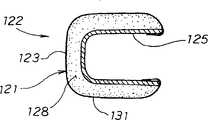
图11是本发明的鞍座(第四实施例)的侧视图,表示的是一体地设置了从座面71的前端向下方或前斜下方延伸的延伸出部121的鞍座122。11 is a side view of the saddle (fourth embodiment) of the present invention, which shows the
借助该延伸出部121,在骑车者采取了将臀部从座面71向车体前方移动了的姿势时可以由延伸出部121的前面123承受臀部或腰部。With this extended
图12是本发明的鞍座(第四实施例)的延伸出部的剖面图,表示的是,弯折鞍座122的底板125的前部形成底板弯折部126,从座面71侧将缓冲材料128延伸到该底板弯折部126的前侧,与座面71同样用表皮材料131覆盖该缓冲材料128。Fig. 12 is a cross-sectional view of the extension part of the saddle (fourth embodiment) of the present invention, showing that the front part of the
因此,在延伸出部121的前面123上抵靠骑车者的臀部或腰部时,可以由更大的面承受臀部或腰部,并且由于夹置了缓冲材料128,因此可以减小作用于臀部或腰部上的面压力。Therefore, when the
图13是图11的13-13剖面图,表示将鞍座122的底板125做成为断面为コ字状,在该底板125的外侧贴附了缓冲材料128,并由表皮材料131覆盖了该缓冲材料128的表面的情况。Fig. 13 is 13-13 sectional view of Fig. 11, shows that the
下面对以上所述的鞍座122的作用进行说明。Next, the function of the above-mentioned
图14是表示本发明的鞍座(第四实施例)的作用的作用图。Fig. 14 is an action diagram showing the action of the saddle (fourth embodiment) of the present invention.
在下坡等的比赛中以高速行驾在路面的不平且容易打滑的拐弯处行走时,为了保持车体的稳定性并防止翻倒,骑车者85使臀部从座面71向车体前方移动,并且下降到座面71的位置之下以降低重心,将一只脚RL(例如是与拐弯的方向相反侧的脚)踏在踏板27上,将另一方的脚LL采取与地面132接近地伸展的姿势,将臀部或腰抵靠在延伸出部121的前面123上或与延伸出部121的前面123接近。When driving at high speed on an uneven and slippery corner in a downhill race, the
由此,在拐弯的过程中,骑车者85降低了重心,除了用操纵手柄22、一方的踏板27支承自行车之外还可以用鞍座122的延伸出部121支撑自行车,可以使车体更加稳定,而且,可以良好地保持骑车者85自身的姿势。另外,若自行车10要翻倒时,通过立刻将脚LL着地而可以防止翻倒。Thus, in the process of turning, the
如以上说明的那样,本发明的第五特征是,设置从座面71的前端向下方或前斜下方延伸的延伸出部121,从而,骑车者85在采取了将臀部从座面71向车体前方移动了的姿势时,由延伸出部121的前面123承受臀部或腰部。As explained above, the fifth characteristic of the present invention is that the extending
通过骑车者85在采取了将臀部从座面71向车体前方移动了的姿势时,由延伸出部121的前面123承受臀部或腰部,可以使臀部或腰部与延伸出部121的前面123面接触,可以防止对臀部或腰部作用大的压力。When the
本发明的第六特征是,如由图11~图13说明的那样,与座面71一体地成形延伸出部121。The sixth characteristic of the present invention is that, as described with reference to FIGS. 11 to 13 , the
由此,可以减少鞍座122的零件数量,可以降低鞍座122的成本,而且可以容易地制造一体成形了延伸出部121的鞍座122。Accordingly, the number of components of the
图15是本发明的鞍座(第五实施例)侧视图,表示的是通过在鞍座本体134的前部下部安装延伸出部135,可以由该延伸出部135承受骑车者的臀部或腰部的鞍座136。Fig. 15 is a side view of the saddle (fifth embodiment) of the present invention, showing that by installing an
图16(a)、(b)是本发明的鞍座(第五实施例)的前部的剖面图。16(a), (b) are sectional views of the front part of the saddle (fifth embodiment) of the present invention.
(a)表示的是在鞍座136的底板137上由螺栓138安装了撑条141,在该撑条141上安装延伸出部135(参照图15)。143…是(…表示多个。以下相同)为了安装延伸出部135而设置在撑条141上的安装孔,144…是为了与螺栓138螺纹结合而安装在底板137上的螺母。(a) shows that the
(b)是图示15的16-16剖面图,表示在撑条141上由小螺钉145、145安装了延伸出部135的情形。(b) is a cross-sectional view taken along line 16-16 of FIG. 15 , showing a state in which the
图17是表示本发明的鞍座的另一实施例(第六实施例)的剖面图,表示的是,通过将鞍座146的底板147向前斜下方折曲而形成弯折部148,在该弯折部148上安装着延伸出部135(参照图15)的例子。151、151(里侧的符号151未图示)是从弯折部148的左右折弯形成的安装面,152、152是为了安装延伸出部135而在安装面151上开设的孔。17 is a cross-sectional view showing another embodiment (the sixth embodiment) of the saddle according to the present invention, showing that the bent portion 148 is formed by bending the bottom plate 147 of the saddle 146 obliquely forward and downward. An example of the extended portion 135 (see FIG. 15 ) is attached to the bent portion 148 . Reference numerals 151 and 151 (symbol 151 on the back side is not shown) are mounting surfaces formed by bending the bent portion 148 left and right, and 152 and 152 are holes opened on the mounting surface 151 for mounting the
如以上用图15及图16(a)、(b)说明的那样,本发明的第七特征在是,通过将延伸出部135通过作为支承构件的撑条141安装在具有座面71的鞍座本体134上,相对于鞍座本体134另成一体。As described above with Fig. 15 and Fig. 16 (a), (b), the seventh feature of the present invention is that the
根据需要可以从鞍座本体134上卸下延伸出部135,由于可以只以鞍座本体134使用,可以提高使用方便性。The
本发明的第八特征是,支承构件为固定在鞍座136上的底板137上的撑条141。只要改变撑条141的形状,则可以改变延伸出部135的位置,可以根据骑车者的喜好配置延伸出部135。The eighth feature of the present invention is that the supporting member is a
本发明的第九特征是,如由图17说明的那样,支承构件是由将设在鞍座146的底部的底板147延伸出而形成。The ninth characteristic of the present invention is that, as explained with reference to FIG. 17 , the supporting member is formed by extending a bottom plate 147 provided at the bottom of the saddle 146 .
由此,可以减少鞍座146的零件数量,可以降低鞍座146的成本。Thereby, the number of parts of the saddle 146 can be reduced, and the cost of the saddle 146 can be reduced.
图18是表示本发明的自行车用骑车者支承构造(第七实施例)的侧视图,表示在鞍座155的前端且下方的鞍座支架56上安装了向上方或后斜上方延伸的伸出片156。Fig. 18 is a side view showing a bicycle rider support structure (seventh embodiment) of the present invention, showing that an extension extending upward or rear obliquely upward is installed on the
鞍座支架56由设在上部的上部构架部56A、设在该上部构架部56A的下方的下部构架部56B、连结在该上部构架部56A及下部构架中56B的各自端部上的圆筒部56C构成,在上部构架部56A上安装上述的伸出片156。The
由伸出片156的前面157承受骑车者的臀部或腰部,在骑车者采取将臀部从座面71向车体前方移动了的姿势时,可以由这样的延伸片156使车体稳定。The rider's buttocks or waist are supported by the
如以上所说明的那样,本发明的第十特征是,在鞍座155的前端的前方且下方的车架16、具体地是在鞍座支架56上设置向上方或后斜上方延伸的伸出片156,在骑车者采取将臀部从座面71向车体前方移动了的姿势时,由伸出片156的前面157承受臀部或腰部。As explained above, the tenth characteristic of the present invention is that the
通过在车架16上设置伸出片156,在骑车者采取将臀部从鞍座155的座面71向车体前方移动了的姿势时,通过由伸出片156的前面157承受臀部或腰部,可以使臀部或腰部与延伸片156的前面面接触,可以防止对臀部或腰部作用大的压力。另外,由于由车架16支承伸出片156,可以提高伸出片156的刚性。By providing the protruding
图19是本发明的鞍座(第八实施例)的侧视图,表示一体地设置从鞍座本体161的座面162的前端向前斜下方延伸的延伸出部163,在鞍座本体161的后部安装了覆盖后轮12上方的树脂制或轻合金制的后挡泥板164的鞍座166。Fig. 19 is a side view of the saddle (eighth embodiment) of the present invention, showing that an extending
鞍座本体161由表皮材料172覆盖该鞍座本体161的外表面,将鞍座本体161的后部侧面形成为膝夹紧部173、174(里侧的膝夹紧部174未图示)。The outer surface of the
延伸出部163在其下端部的内侧安装着支承延伸出部163的树脂制的支承构件176。A
后挡泥板164延伸到比通过后车轮12车轴67(参照图2)的中心的铅垂线120更靠后方。The
图20是本发明的鞍座(第八实施例)的立体图,表示的是鞍座166,该鞍座166,从座面162侧一边弯曲一边向前斜下方延伸出延伸出部163,在座面162的下方的侧面上形成着面积大的膝夹紧部173、174(里面的膝夹紧部174未图示),与鞍座本体161的后部连续地一体地安装着后挡泥板164。Fig. 20 is a perspective view of a saddle (eighth embodiment) of the present invention, showing a
图21是本发明的鞍座(第八实施例)俯视图,鞍座166通过使鞍座本体161的后部的宽度变宽而形成面积大的座面162,通过加大膝夹紧部173、174的间隔B1,提高了座面162的乘坐舒适性和膝夹紧部173、174的保持性,通过使鞍座本体161的前部的宽度B2变窄,在骑车者从座面162浮起腰时不会妨碍腿部的动作。21 is a top view of the saddle (eighth embodiment) of the present invention. The
另外,鞍座166通过在后挡泥板164的前部设置将两侧缘部一边向后方弯曲并扩宽的前部弯曲部181、182,从而使这些前部弯曲部181、182上也具有与鞍座本体161的膝夹紧部173、174连续的膝夹紧部的功能,通过将这些前部弯曲部181、182的后部的宽度B3扩大为与膝夹紧部173、174的间隔B1基本相等,可以确实地挡住后车轮12溅起的泥。In addition, the
图22是图21的22-22剖面图。鞍座本体166由树脂制的鞍座基体171、树脂制的加强板186、由钢材构成的撑条192、筒半体193、194、鞍座支柱197及螺母构件198、支承构件176组成,该加强板186由螺栓185安装在上述鞍座基体171的下面的中央部,该撑条192将其后端插入到设在上述加强板186的后部的槽187中,并且将其前部由螺栓191安装在突出于鞍座基体171的下面的突出部188上,上述筒半体193、194上下夹该撑条192,上述鞍座支柱197及螺母构件198再上下夹筒半体193、194、并用螺栓196连接,上述支承构件176架设在上述延伸出部163与鞍座基体171的突出部188上。Fig. 22 is a sectional view taken along line 22-22 of Fig. 21 . The
鞍座基体171由于具有弹性而提高了乘车者的乘坐舒适性,在其外面上配置了缓冲构件199,由上述的表皮材料172覆盖该缓冲材料199的外表面。The saddle base 171 improves the riding comfort of the occupant due to its elasticity, and a cushioning member 199 is disposed on its outer surface, and the outer surface of the cushioning material 199 is covered by the above-mentioned skin material 172 .
加强板186通过设置在鞍座基体171的中央部而提高了刚性,可以充分地支承乘坐者的体重。The reinforcement plate 186 is provided at the center portion of the saddle base 171 to increase rigidity, and can sufficiently support the weight of the occupant.
筒半体193、194通过松开螺栓196可以调整相对于鞍座支柱197的鞍座基体171侧的前后的倾斜。The front-back inclination of the cylinder half bodies 193 and 194 on the side of the saddle base 171 with respect to the saddle post 197 can be adjusted by loosening the bolt 196 .
支承构件176,其横断面为コ字状,将其前端用螺栓203固定在延伸出部163的内侧,将其后端与撑条192一起用螺栓191固定在鞍座基体171的突出部188上。The supporting
后挡泥板164从内侧用小螺钉204…(…表示多个。以下相同)安装在鞍座基体171的侧壁上。The
作为本发明的自行车用鞍座,也可以将鞍座的底板向车体后方延伸并使鞍座的后部两侧部向下方突出而形成膝夹紧部,从而在鞍座上一体地设置膝夹紧部。As the bicycle saddle of the present invention, the bottom plate of the saddle may be extended to the rear of the vehicle body, and the rear side portions of the saddle may protrude downward to form a knee clamping portion, thereby integrally providing the knee joint on the saddle. clamping part.
本发明由于上述构成可以发挥如下的效果。The present invention exhibits the following effects due to the above configuration.
第一技术方案的自行车用鞍座,由于通过使骑车者坐的座面的两侧面向后方伸出,并且使该伸出部侧面也向下方伸出,而形成左右一对膝夹紧部,骑车者用膝的内侧、大腿的内侧夹这些膝夹紧部。因此自行车在行驶中,骑车者可以用车把、踏板及膝夹紧部支撑自行车,可以提高自行车的稳定性,并且可以良好地保持骑车者的姿势。In the bicycle saddle according to the first technical solution, a pair of left and right knee clamping parts are formed by making both sides of the seat surface on which the rider sits protrude backward, and making the side of the protruding part protrude downward. , The rider clamps these knee clamping parts with the inner side of the knee and the inner side of the thigh. Therefore, when the bicycle is running, the cyclist can support the bicycle with the handlebars, the pedals and the knee clamping part, which can improve the stability of the bicycle and maintain the posture of the cyclist well.
本发明的第二技术方案的自行车用鞍座,由于将膝夹紧部与座面成形为一体。因此,可以减少鞍座的零件数量,可以降低鞍座的成本。另外,可以容易地制造一体地成形了膝夹紧部的鞍座。In the bicycle saddle according to the second aspect of the present invention, the knee grip part and the seat surface are integrally formed. Therefore, the number of parts of the saddle can be reduced, and the cost of the saddle can be reduced. In addition, the saddle in which the knee grip portion is integrally formed can be easily manufactured.
本发明的第三技术方案的自行车用鞍座,由于相对于具有座面的鞍座本体另成一体地构成膝夹紧部。因此,可以根据需要卸下膝夹紧部,可以提高使用方便性。而且,可以在现有的只由座面构成的鞍座上安装膝夹紧部。In the bicycle saddle according to the third aspect of the present invention, the knee clamp portion is formed integrally with the saddle body having the seat surface. Therefore, the knee clamp can be detached as needed, and usability can be improved. Furthermore, the knee clamping part can be installed on the existing saddle composed of only the seat surface.
本发明的第四技术方案的自行车用鞍座,由于通过在座面的后部安装板构件,由该板构件兼用作覆盖后轮的上方的后挡泥板和骑车者用膝的内侧、大腿的内侧夹的膝夹紧部,该板部形成有向车体后方延伸的后部延伸出部和从该后部延伸出部的前部两侧部向下方延伸的左右一对下方伸出部,因此,除了由膝夹紧部带来车体的稳定化之外,还可以防止后车轮的溅泥或飞起的石头等。In the saddle for bicycles according to the fourth aspect of the present invention, since the plate member is installed on the rear portion of the seat surface, the plate member can also be used as the rear fender covering the upper part of the rear wheel and the inner side of the rider's knee and thigh. The knee clamping portion of the inner side clip, the plate portion is formed with a rear extension extending toward the rear of the vehicle body and a pair of left and right lower extensions extending downward from both sides of the front portion of the rear extension. Therefore, in addition to the stabilization of the vehicle body brought about by the knee clamp, it is also possible to prevent splashing of mud or flying stones from the rear wheels.
本发明的第五技术方案的自行车用鞍座,由于通过设置从座面的前端向下方或前斜下方延伸的延伸出部,在骑车者采用将臀部从座面向车体前方移动了的姿势时,用延伸出部的前面承受臀部或腰部,因此,在骑车者采用将臀部从座面向车体前方移动了的姿势时,通过用延伸出部的前面承受臀部或腰部,可以使臀部或腰部与延伸出部的前面面接触,可以防止对臀部或腰部作用大的压力。In the bicycle saddle according to the fifth aspect of the present invention, since the extending portion extending downward or obliquely downward from the front end of the seat surface is provided, the rider moves the buttocks from the seat surface to the front of the vehicle body. When using the front part of the extended part to bear the buttocks or waist, therefore, when the rider adopts a posture that moves the buttocks from the seat to the front of the vehicle body, by receiving the buttocks or waist on the front side of the extended part, the hips or the waist can be The waist is in contact with the front surface of the extension, so that a large pressure on the buttocks or the waist can be prevented.
本发明的第六技术方案的自行车用鞍座,由于与座面一体地成形延伸出部,因此,可以减少鞍座的零件数量,可以降低鞍座的成本。而且可以容易地制造一体成形了延伸出部的鞍座。In the bicycle saddle according to the sixth aspect of the present invention, since the extending portion is formed integrally with the seat surface, the number of parts of the saddle can be reduced, and the cost of the saddle can be reduced. Furthermore, the saddle in which the extended portion is integrally formed can be easily manufactured.
本发明的第七技术方案的自行车用鞍座,由于通过支承构件将延伸出部安装在具有座面的鞍座本体上,相对于鞍座本体分另成一体地形成延伸出部,因此,可以根据需要卸下延伸出部,可以提高使用方便性。In the bicycle saddle according to the seventh aspect of the present invention, since the extension part is attached to the saddle body having a seat surface through the supporting member, and the extension part is formed separately and integrally with the saddle body, it can be Ease of use can be improved by removing the extensions as needed.
本发明的第八技术方案的自行车用鞍座,由于将支承构件构成为固定于鞍座本体上的底板上的撑条,因此,如果变更撑条的形状,则可以变更延伸出部的位置,可以根据骑车者的喜好配置延伸出部。In the bicycle saddle according to the eighth aspect of the present invention, since the supporting member is constituted as a stay fixed to the bottom plate on the saddle body, if the shape of the stay is changed, the position of the extended part can be changed, The extension can be configured according to the rider's preference.
本发明的第九技术方案的自行车用鞍座,由于支承构件是由使设置在鞍座本体的底部上的底板延伸出而成的,因此,可以减少鞍座的零件数量,可以降低鞍座的成本。In the bicycle saddle of the ninth technical solution of the present invention, since the supporting member is formed by extending the bottom plate provided on the bottom of the saddle body, the number of parts of the saddle can be reduced, and the weight of the saddle can be reduced. cost.
本发明的第十技术方案的自行车用骑车者支承构造,由于通过在鞍座的前端的前方且在下方的车架上设置向上方或后斜上方伸出的伸出片,在骑车者采取将臀部从座面移动到了车体前方的姿势时,由伸出片的前面承受臀部或腰部,因此,通过在车架上设置伸出片,在骑车者采取将臀部从座面移动到了车体前方的姿势时,由延伸片的前面承受臀部或腰部,由此,可以使臀部或腰部与延伸片的前面面接触,可以防止对臀部或腰部作用大地压力。According to the tenth technical solution of the present invention, the rider support structure for a bicycle is provided with a protruding piece that protrudes upwards or obliquely upwards behind the front end of the saddle on the frame below the front end of the saddle. When the buttocks are moved from the seat surface to the front of the vehicle body, the buttocks or the waist are supported by the front of the protruding piece. In the posture in front of the body, the buttocks or the waist are supported by the front of the extension piece, thereby, the buttocks or the waist can be brought into contact with the front surface of the extension piece, and large pressure can be prevented from acting on the buttocks or the waist.
Claims (4)
Translated fromChineseApplications Claiming Priority (4)
| Application Number | Priority Date | Filing Date | Title |
|---|---|---|---|
| JP2002119413 | 2002-04-22 | ||
| JP119413/2002 | 2002-04-22 | ||
| JP2002160826AJP2004001653A (en) | 2002-04-22 | 2002-05-31 | Bicycle saddle and bicycle driver support structure |
| JP160826/2002 | 2002-05-31 |
Publications (2)
| Publication Number | Publication Date |
|---|---|
| CN1453173A CN1453173A (en) | 2003-11-05 |
| CN1229248Ctrue CN1229248C (en) | 2005-11-30 |
Family
ID=29272313
Family Applications (1)
| Application Number | Title | Priority Date | Filing Date |
|---|---|---|---|
| CNB031082181AExpired - Fee RelatedCN1229248C (en) | 2002-04-22 | 2003-03-25 | bicycle saddle |
Country Status (4)
| Country | Link |
|---|---|
| US (1) | US6871907B2 (en) |
| JP (1) | JP2004001653A (en) |
| CN (1) | CN1229248C (en) |
| TW (1) | TW589263B (en) |
Families Citing this family (8)
| Publication number | Priority date | Publication date | Assignee | Title |
|---|---|---|---|---|
| US8297696B2 (en)* | 2005-11-17 | 2012-10-30 | Louis Chuang | Bicycle saddle |
| US8047604B2 (en)* | 2005-11-17 | 2011-11-01 | Louis Chuang | Bicycle saddle |
| US7699392B2 (en)* | 2006-01-27 | 2010-04-20 | Louis Chuang | Bicycle saddle |
| BE1018142A3 (en)* | 2007-10-05 | 2010-06-01 | D En G Projects | Bicycle saddle, has seat body for supporting measuring seating surface, and cover provided for covering seating surface of saddle and portion of seat, where saddle is mounted on bicycle frame of bicycle |
| JP5084667B2 (en)* | 2008-08-27 | 2012-11-28 | 株式会社丸山製作所 | Riding machine |
| ITTO20090103A1 (en)* | 2009-02-13 | 2010-08-14 | Alessandro Pallozzi | SUPPORT FOR CHILDREN'S LEGS, IN PARTICULAR FOR MOUNTAIN BICYCLES AND DESCENT BIKES |
| CN103158804A (en)* | 2013-03-19 | 2013-06-19 | 李文军 | Bike saddle construction method |
| JP7746753B2 (en)* | 2021-09-09 | 2025-10-01 | スズキ株式会社 | Front fender |
Family Cites Families (9)
| Publication number | Priority date | Publication date | Assignee | Title |
|---|---|---|---|---|
| US3432204A (en)* | 1967-08-24 | 1969-03-11 | Schwinn Bicycle Co | Unicycle saddle |
| FR2613684B1 (en)* | 1987-04-09 | 1997-08-14 | Beylet Daniel | BICYCLE SUPPORT SADDLE |
| IT221892Z2 (en) | 1991-05-29 | 1994-12-06 | Selle Italia Srl | SADDLE STRUCTURE FOR CYCLES AND SIMILAR, WITH IMPROVED COMFORT |
| US5362126A (en)* | 1992-07-13 | 1994-11-08 | Bontrager Keith D | Bicycle saddle |
| USD368242S (en)* | 1994-11-14 | 1996-03-26 | Roadmaster Corporation | Bicycle |
| JPH08281508A (en) | 1995-04-11 | 1996-10-29 | Bridgestone Cycle Co | Frame for bicycle |
| US5791730A (en)* | 1996-08-09 | 1998-08-11 | Avocet, Inc. | Bicycle seat |
| US5918904A (en)* | 1996-12-16 | 1999-07-06 | Hanesworth; Don | Snap on mud fenders for mountain bikes |
| US6231122B1 (en)* | 1999-09-09 | 2001-05-15 | Trek Bicycle Corporation | Bicycle saddle |
- 2002
- 2002-05-31JPJP2002160826Apatent/JP2004001653A/ennot_activeWithdrawn
- 2003
- 2003-03-25CNCNB031082181Apatent/CN1229248C/ennot_activeExpired - Fee Related
- 2003-03-27TWTW092106982Apatent/TW589263B/ennot_activeIP Right Cessation
- 2003-03-31USUS10/401,745patent/US6871907B2/ennot_activeExpired - Lifetime
Also Published As
| Publication number | Publication date |
|---|---|
| JP2004001653A (en) | 2004-01-08 |
| US6871907B2 (en) | 2005-03-29 |
| TW200305520A (en) | 2003-11-01 |
| CN1453173A (en) | 2003-11-05 |
| US20030222488A1 (en) | 2003-12-04 |
| TW589263B (en) | 2004-06-01 |
Similar Documents
| Publication | Publication Date | Title |
|---|---|---|
| US20040035624A1 (en) | Components for a three-wheeled vehicle to permit leaning of the driver | |
| US8876136B2 (en) | Easy riding bicycle | |
| TW201204588A (en) | Bicycle seat tube | |
| JP7661181B2 (en) | Bike | |
| CN1605533A (en) | Fuel cell assembled structure for saddle riding type vehicle | |
| CN1317156C (en) | Bodywork structure of two-wheel motor | |
| CN1229248C (en) | bicycle saddle | |
| CN1944169A (en) | Motorcycle | |
| US7270213B2 (en) | Wheeled vehicle with foot rest | |
| US6837504B2 (en) | Scooter stabilizing systems and methods | |
| KR101042540B1 (en) | Bicycle saddle assembly | |
| TW202108433A (en) | Leaning vehicle | |
| CN1305729C (en) | Frame structure of bicycle | |
| CN1749095A (en) | Saddle type vehicle | |
| CN108688754B (en) | A step-by-step vehicle | |
| US8668219B1 (en) | Bicycle thrust apparatus | |
| CN100465048C (en) | Wheeled vehicles with footrests | |
| US20020030342A1 (en) | Handcycle | |
| TW200610692A (en) | Scooter type motorcycle | |
| CN2633723Y (en) | Front hopper type multifunction tricycle | |
| CN119840760A (en) | Adaptive adjustment's special tricycle frame structure | |
| JPH04321480A (en) | Bicycle frame | |
| KR20080005103U (en) | Exercise device of unicycle | |
| JP2003127953A (en) | Body frame for motorcycle | |
| CN1240736A (en) | Handlebar structure for bicycle |
Legal Events
| Date | Code | Title | Description |
|---|---|---|---|
| C06 | Publication | ||
| PB01 | Publication | ||
| C10 | Entry into substantive examination | ||
| SE01 | Entry into force of request for substantive examination | ||
| C14 | Grant of patent or utility model | ||
| GR01 | Patent grant | ||
| C17 | Cessation of patent right | ||
| CF01 | Termination of patent right due to non-payment of annual fee | Granted publication date:20051130 Termination date:20130325 |