Movatterモバイル変換


[0]ホーム

URL:


CN1227465C - Continuously variable transmission - Google Patents

Continuously variable transmission
Download PDF

Info

Publication number
CN1227465C
CN1227465CCNB00818383XACN00818383ACN1227465CCN 1227465 CCN1227465 CCN 1227465CCN B00818383X ACNB00818383X ACN B00818383XACN 00818383 ACN00818383 ACN 00818383ACN 1227465 CCN1227465 CCN 1227465C
Authority
CN
China
Prior art keywords
transmission
bearing
drive member
rotating
attached
Prior art date
Legal status (The legal status is an assumption and is not a legal conclusion. Google has not performed a legal analysis and makes no representation as to the accuracy of the status listed.)
Expired - Fee Related
Application number
CNB00818383XA
Other languages
Chinese (zh)
Other versions
CN1423734A (en
Inventor
D·C·米勒
Current Assignee (The listed assignees may be inaccurate. Google has not performed a legal analysis and makes no representation or warranty as to the accuracy of the list.)
Fallbrook Intellectual Property Co LLC
Original Assignee
Motion Technologies LLC
Priority date (The priority date is an assumption and is not a legal conclusion. Google has not performed a legal analysis and makes no representation as to the accuracy of the date listed.)
Filing date
Publication date
Application filed by Motion Technologies LLCfiledCriticalMotion Technologies LLC
Publication of CN1423734ApublicationCriticalpatent/CN1423734A/en
Application grantedgrantedCritical
Publication of CN1227465CpublicationCriticalpatent/CN1227465C/en
Anticipated expirationlegal-statusCritical
Expired - Fee Relatedlegal-statusCriticalCurrent

Links

Images

Classifications

Landscapes

Abstract

A continuously variable transmission is disclosed for use with rotationally or linearly driven machines and vehicles. The single shaft transmission provides a simple manual shifting method for a user. Another embodiment is disclosed that automatically shifts gears based on the rotational speed of the wheels. Moreover, practical commercialization of traction roller transmissions requires improvements in reliability, ease of shifting, function and simplicity of the transmission. The disclosed transmission may be used in vehicles such as automobiles, motorcycles, and bicycles. The transmission may be driven, for example, by a power transmission mechanism such as a sprocket, gear, pulley or rod, optionally driving a one-way clutch attached to one end of the main shaft.

Description

Translated fromChinese
无级变速传动装置Continuously variable transmission

技术领域technical field

本发明领域涉及传动装置。本发明更特别涉及无级变速传动装置。The field of the invention relates to transmissions. The present invention relates more particularly to continuously variable transmissions.

背景技术Background technique

为了提供一无级变速传动装置,开发了各种牵引滚子传动装置,其中动力通过支承于壳体中的诸牵引滚子在转矩输入盘与输出盘之间传递。在这样的传动装置中,诸牵引滚子安装在各支承结构上,当支承结构转动时使诸牵引滚子与各转矩盘在不同的直径的圆上接合,其中不同的直径根据要求的传动比而定。In order to provide a continuously variable transmission, traction roller transmissions have been developed in which power is transmitted between torque input and output discs via traction rollers supported in a housing. In such a transmission, traction rollers are mounted on each support structure so that when the support structure rotates, the traction rollers engage torque discs on circles of different diameters depending on the desired transmission. It depends.

然而,这些传统的解决方法的成果已受限制,例如,在颁予Schievelbusch的美国专利No.5236403中,公开了一用于具有一可变可调传动比的车辆的驱动毂。Schievelbusch讲述了采用两个隔板,在诸牵引滚子的每一侧上用一个,用来使每一滚子的转动轴斜移。然而,采用两隔板可能是很复杂的,因为在传动装置的换档过程中需要许多元件来调节各隔板。关于该传动装置的另一困难在于其具有一导向环,其构成得相对于每一滚子主要是固定的。由于导向环是固定的,移动每一牵引滚子的转动轴是困难的。这种设计还有另一限制在于其需要采有两个半轴,在诸滚子的每一侧上用一个,用来在该两个半轴的中间形成一间隙。该间隙是必需的,因为诸滚子以转动而不是以直线滑动被移动。采用两个轴是不希望的并且需要一复杂的紧固装置以防在传动装置被偶而碰撞时各轴弯曲,就象在传动装置用于车辆中时经常发生的情况那样。这种设计的还有另一限制在于其并不能提供一自动的传动装置。However, these conventional solutions have had limited success, for example, in US Patent No. 5,236,403 to Schievelbusch, which discloses a drive hub for a vehicle having a variable adjustable transmission ratio. Schievelbusch teaches the use of two spacers, one on each side of the traction rollers, to skew the axis of rotation of each roller. However, the use of two dividers can be complicated because many components are required to adjust each divider during a shift of the transmission. A further difficulty with this transmission is that it has a guide ring which is constructed essentially stationary relative to each roller. Since the guide ring is fixed, it is difficult to move the axis of rotation of each traction roller. Yet another limitation of this design is that it requires two half shafts, one on each side of the rollers, to create a gap between the two half shafts. This clearance is necessary because the rollers are moved in rotation rather than linear sliding. The use of two shafts is undesirable and requires a complex fastening arrangement to prevent bending of the shafts should the transmission be accidentally bumped, as often happens when the transmission is used in a vehicle. Yet another limitation of this design is that it does not provide an automatic transmission.

因此,需要一种无级变速传动装置,其具有更简单的换档方法、单根轴和一具有基本上均匀的外表面的支承环。此外,需要一自动的牵引滚子传动装置,其构成为自动换档。而且牵引滚子传动装置的实际商品化要求在可靠性、换档简易性、功能和传动装置的简单性诸方面的改进。Accordingly, there is a need for a continuously variable transmission having a simpler shifting method, a single shaft, and a support ring having a substantially uniform outer surface. In addition, an automatic traction roller transmission is required, which is designed as an automatic gearshift. Furthermore, the actual commercialization of traction roller drives requires improvements in reliability, ease of shifting, functionality and simplicity of the transmission.

发明内容Contents of the invention

本发明包括一传动装置,供转动地或直线地驱动的机械和车辆之用。例如本传动装置可以用于如钻床、涡轮机和食品加工设备等机械,以及如汽车、摩托车和自行车等车辆。该传动装置可以例如由一动力传动机构如链轮、齿轮、带轮或杆来驱动,任选地驱动连接于主轴的一端的单向离合器。The invention includes a transmission for rotationally or linearly driven machines and vehicles. For example, the transmission can be used in machinery such as drill presses, turbines and food processing equipment, as well as in vehicles such as automobiles, motorcycles and bicycles. The transmission may for example be driven by a power transmission mechanism such as a sprocket, gear, pulley or rod, optionally driving a one-way clutch connected to one end of the main shaft.

本发明的一个实施方案中,传动装置包括:一可转动的驱动构件;三个或更多个动力调节装置,其中每一动力调节装置分别绕一位于每一动力调节装置内部中心的转动轴转动;一提供一支承表面的支承构件,该支承表面与每一动力调节装置摩擦接触,其中支承构件绕一位于支承构件内部中心的轴转动;至少一个平台用以致动支承构件的轴向移动和用以致动动力调节装置的转动轴的转移,其中平台提供一凸起表面;至少一个固定支承件,其不能转动地围绕由支承构件限定的转动轴,其中至少一个固定支承件提供一凹入表面;以及多个心轴支承件,其中每一心轴支承件与平台的凸起表面和固定支承件的凹入表面滑动接合,并且其中每一心轴支承件对应着平台的轴向移动而调节动力调节装置的转动轴。In one embodiment of the present invention, the transmission device includes: a rotatable driving member; three or more power regulating devices, wherein each power regulating device rotates around a rotating shaft located at the inner center of each power regulating device ; a support member providing a bearing surface in frictional contact with each power regulating device, wherein the support member rotates about an axis located at the inner center of the support member; at least one platform for actuating the axial movement of the support member and to actuate the transfer of the axis of rotation of the power adjustment device, wherein the platform provides a convex surface; at least one fixed support, which cannot rotate around the axis of rotation defined by the support member, wherein the at least one fixed support provides a concave surface; and a plurality of spindle supports, wherein each spindle support is in sliding engagement with the convex surface of the platform and the concave surface of the stationary support, and wherein each spindle support adjusts the power adjustment device in response to axial movement of the platform axis of rotation.

在另一实施方案中,传动装置包括:一可转动的驱动构件;三个或更多个动力调节装置,其中每一动力调节装置分别绕着分别为各动力调节装置的中心的转动轴转动;一提供一支承表面的支承构件,该支承表面与每一动力调节装置摩擦接触,一可转动的驱动构件用以转动每一动力调节装置;一具有多个倾斜的斜台的轴承盘用以致动该驱动构件的转动;一螺旋弹簧用以将可转动的驱动构件偏压到各动力调节装置上;至少一个锁定棘爪棘轮,其中锁定棘爪棘轮刚性地连接于该可转动的驱动构件,至少一个锁定棘爪可操作地连接于螺旋弹簧;和至少一个锁定棘爪用来对应着从动力调节装置上脱开的该可转动的驱动构件而锁定该锁定棘爪棘轮。In another embodiment, the transmission device includes: a rotatable driving member; three or more power regulating devices, wherein each power regulating device rotates around a rotation axis respectively being the center of each power regulating device; a support member providing a bearing surface in frictional contact with each power regulating device, a rotatable drive member for rotating each power regulating device; a bearing plate having a plurality of inclined ramps for actuating rotation of the drive member; a coil spring for biasing the rotatable drive member to each power adjustment device; at least one locking pawl ratchet, wherein the locking pawl ratchet is rigidly connected to the rotatable drive member, at least A locking pawl is operatively connected to the coil spring; and at least one locking pawl is used to lock the locking pawl ratchet correspondingly to the rotatable drive member disengaged from the power adjusting device.

在又一实施方案中,传动装置包括:一可转动的驱动构件;三个或更多个动力调节装置,其中每一动力调节装置分别绕着分别是每一动力调节装置的中心的轴转动;一提供一支承表面的支承构件,该支承表面与每一动力调节装置摩擦接触,其中支承构件绕一位于支承构件内部中心的轴转动;一具有多个倾斜的斜台的轴承盘用以致动该驱动构件的转动;一螺纹件共轴地和刚性地连接于该可转动的驱动构件或轴承盘;以及一螺母,如果螺纹件连接于可转动的驱动构件,该螺母就共轴地和刚性地连接于轴承盘,或者如果螺纹件刚性地连接于轴承盘,该螺母就共轴地和刚性地连接于可转动的驱动构件,其中轴承盘的倾斜的斜台比螺纹件具有更大的导程(lead)。In yet another embodiment, the transmission comprises: a rotatable drive member; three or more power regulating devices, wherein each power regulating device rotates about an axis which is respectively the center of each power regulating device; a support member providing a bearing surface in frictional contact with each power regulating device, wherein the support member rotates about an axis centrally located within the support member; a bearing plate having a plurality of inclined ramps for actuating the rotation of the drive member; a threaded member coaxially and rigidly connected to the rotatable drive member or bearing disc; and a nut, if the threaded member is connected to the rotatable drive member, the nut is coaxially and rigidly connected Attached to the bearing disc, or if the threaded member is rigidly attached to the bearing disc, the nut is coaxially and rigidly attached to the rotatable drive member, wherein the inclined ramp of the bearing disc has a greater lead than the threaded member (lead).

附图说明Description of drawings

图1为本发明的传动装置的侧剖视图;Fig. 1 is the side sectional view of transmission device of the present invention;

图2为图1的传动装置的局部透视图;Figure 2 is a partial perspective view of the transmission of Figure 1;

图3为图1的传动装置的两个固定支承件的透视图;Figure 3 is a perspective view of two fixed supports of the transmission of Figure 1;

图4为图1的传动装置的局部端面剖视图;Fig. 4 is a partial end face sectional view of the transmission device of Fig. 1;

图5为图1的传动装置的一驱动盘、轴承罩、螺纹件和斜台轴承的透视图;Figure 5 is a perspective view of a drive plate, bearing housing, screw and ramp bearing of the transmission of Figure 1;

图6为图1的传动装置的一棘轮与棘爪子系统的透视图,其用于与传动装置接合和脱开;6 is a perspective view of a ratchet and pawl subsystem of the transmission of FIG. 1 for engaging and disengaging the transmission;

图7为图1的传动装置的局部透视图,其中特别拆去了一可转动的驱动盘;Figure 7 is a partial perspective view of the transmission of Figure 1 with a rotatable drive disc removed;

图8为图1的传动装置的局部透视图,其中特别拆去了毂壳;Figure 8 is a partial perspective view of the transmission of Figure 1 with the hub shell particularly removed;

图9为图1的传动装置的局部透视图,其中自动地进行换档;Fig. 9 is a partial perspective view of the transmission of Fig. 1, wherein shifting is performed automatically;

图10为换档手柄的透视图,其机械地连接于图1的传动装置;Figure 10 is a perspective view of a shift handle mechanically connected to the transmission of Figure 1;

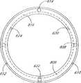
图11为图1中所示传动装置的一推力轴承的端视图,其供传动装置的自动换档之用;Figure 11 is an end view of a thrust bearing of the transmission shown in Figure 1, which is used for automatic shifting of the transmission;

图12为图1中所示传动装置的重块结构的端面视图;Figure 12 is an end view of the weight structure of the transmission shown in Figure 1;

图13为用螺栓固定于平面表面上的传动装置的另一实施方案的透视图;Figure 13 is a perspective view of another embodiment of the actuator bolted to a planar surface;

图14为图13中所示传动装置的侧剖视图;Figure 14 is a side sectional view of the transmission shown in Figure 13;

图15为图1中传动装置的示意端面视图,示出横过传动装置的自动部分的隔离件延伸部分布线的线缆;Figure 15 is a schematic end view of the transmission of Figure 1 showing cables routed across the spacer extension of the automatic portion of the transmission;

图16为图13中所示传动装置的线缆布线的示意端面视图。FIG. 16 is a schematic end view of the cable routing of the transmission shown in FIG. 13 .

具体实施方式Detailed ways

以下详述针对本发明某些具体的实施方案。然而,本发明可以按照权利要求书所限定和包括的许多不同方式来实施。在该说明书中,涉及到的诸附图中,相同的部件均用相同的标号表示。此外,本发明的各实施方案可以包括若干新颖的特征,这些特征的不只一个单独决定着其要求的特性或者这些特征对实施本文描述的发明是必不可少的。The following detailed description is directed to certain specific embodiments of the present invention. However, the invention can be implemented in many different ways as defined and covered by the claims. In this specification, in the various drawings referred to, the same components are denoted by the same reference numerals. Furthermore, embodiments of the invention may include several novel features, no one of which is solely responsible for its required attributes or which are essential to practicing the invention described herein.

本发明包括一种无级变速传动装置,其可以与需要传动装置的任何类型的机械相结合使用。例如,传动装置可以用于(i)机动的车辆如汽车、摩托车,或船舶,(ii)非机动的车辆如自行车、三轮车、踏板车、锻炼设备或(iii)工业设备如钻床、动力设备,或纺织机。The present invention includes a continuously variable transmission that can be used in conjunction with any type of machine that requires a transmission. For example, transmissions can be used in (i) motorized vehicles such as automobiles, motorcycles, or boats, (ii) non-motorized vehicles such as bicycles, tricycles, scooters, exercise equipment, or (iii) industrial equipment such as drill presses, power equipment , or looms.

参照图1和2,公开了一种无级变速传动装置100。传动装置100被覆盖在由毂盖67盖住的毂壳40内。在传动装置100的中心是三个或更多个动力调节装置1a、1b和1c,它们是球形的并且沿周边等间隔围绕传动装置100的中心线或转动轴。如由图2中更明显看到的,心轴3a、3b和3c插过动力调节装置1a、1b和1c的中心而限定动力调节装置1a、1b和1c的转动轴。在图1中,动力调节装置的转动轴示于水平方向。心轴支承件2a-2f垂直地连接于和连接在心轴3a、3b和3c的各外露端。在一个实施方案中,每一心轴支承件具有一个孔以接纳心轴3a、3b和3c其中之一的一端。心轴3a、3b和3c还具有心轴滚子4a-4f,其在心轴支承件2a-2f的外面共轴地和滑动地定位在心轴3a、3b和3c的外露端上。Referring to Figures 1 and 2, a continuouslyvariable transmission 100 is disclosed. Thetransmission 100 is covered within ahub shell 40 covered by ahub cover 67 . At the center of thetransmission 100 are three or morepower conditioning devices 1a, 1b and 1c, which are spherical and equally spaced circumferentially around the centerline or axis of rotation of thetransmission 100 . As can be seen more clearly from Figure 2, thespindles 3a, 3b and 3c are inserted through the centers of the power regulatingdevices 1a, 1b and 1c to define the axes of rotation of the power regulatingdevices 1a, 1b and 1c. In Fig. 1, the rotation axis of the power regulating device is shown in the horizontal direction. The mandrel supports 2a-2f are vertically attached to and attached to the respective exposed ends of themandrels 3a, 3b and 3c. In one embodiment, each mandrel support has a hole to receive one end of one of themandrels 3a, 3b and 3c. Thespindles 3a, 3b and 3c also have spindle rollers 4a-4f coaxially and slidingly positioned on the exposed ends of thespindles 3a, 3b and 3c outside the spindle supports 2a-2f.

当通过使心轴3a、3b和3c斜移来改变动力调节装置1a、1b和1c的转动轴时,心轴滚子4a-4f的每一个沿在固定支承件5a、5b内切出的沟槽6a-6f而动。参照图1和3,固定支承件5a、5b基本上为平行盘的形式,具有沿传动装置100的中心线的转动轴线。沟槽6a-6f从固定支承件5a、5b的外周边向传动装置100的中心线方向延伸。虽然沟槽6a-6f的侧面基本上是平行的,但沟槽6a-6f的底表面在其向传动装置100的中心线方向延伸时形成渐减的半径。当通过改变动力调节装置1a、1b和1c的转动轴将传动装置100变换到一较低速档或较高速档时,位于一单个心轴3a、3b和3c上的每对心轴滚子4a-4f沿它们的相应沟槽6a-6f向相反的方向运动。When changing the rotation axis of the power regulatingdevices 1a, 1b and 1c by tilting thespindles 3a, 3b and 3c, each of the spindle rollers 4a-4f follows the grooves cut in thefixed supports 5a, 5b Slots 6a-6f move. Referring to FIGS. 1 and 3 , the fixed supports 5 a , 5 b are substantially in the form of parallel discs with an axis of rotation along the center line of thetransmission 100 . The grooves 6 a - 6 f extend from the outer periphery of the fixed supports 5 a , 5 b toward the centerline of thetransmission 100 . Although the sides of the grooves 6 a - 6 f are substantially parallel, the bottom surfaces of the grooves 6 a - 6 f form a decreasing radius as they extend toward the centerline of thetransmission 100 . When thetransmission 100 is shifted to a lower gear or a higher gear by changing the axis of rotation of the power regulatingdevices 1a, 1b and 1c, each pair of spindle rollers 4a on asingle spindle 3a, 3b and 3c -4f move in opposite directions along their respective grooves 6a-6f.

参照图1和3,固定支承件5a、5b中的中心孔7a、7b可以使一空心轴10插过固定支承件5a、5b。参照图4,在本发明的一个实施方案中,一个或更多个固定支承件孔7a、7b可以具有非圆柱形状14,其配装到一沿着空心轴10的相应的非圆柱形体15上以防止固定支承件5a、5b与空心轴10之间的任何相对转动。如果固定支承件5a、5b的刚度不足,可以采用附加结构使任何相对转动或固定支承件5a、5b的弯曲减至最小。固定支承件5a、5b的这类运动会导致对沿沟槽6a-6f运动时的心轴滚子4a-4f的约束。Referring to Figures 1 and 3, central holes 7a, 7b in thefixed supports 5a, 5b allow ahollow shaft 10 to be inserted through thefixed supports 5a, 5b. Referring to Figure 4, in one embodiment of the invention, one or more of the fixed support holes 7a, 7b may have anon-cylindrical shape 14 which fits onto a corresponding non-cylindrical body 15 along thehollow shaft 10 In order to prevent any relative rotation between thefixed supports 5 a , 5 b and thehollow shaft 10 . If the rigidity of the fixedsupports 5a, 5b is insufficient, additional structures may be employed to minimize any relative rotation or bending of the fixedsupports 5a, 5b. Such movement of the fixedsupports 5a, 5b results in a constraint on the spindle rollers 4a-4f as they move along the grooves 6a-6f.

如图4和7中所示,附加结构可以采取连接在固定支承件5a、5b之间的隔离件8a、8b和8c的形式。隔离件8a、8b和8c增加固定支承件5a、5b之间的刚度,并且在一实施方案中,位于固定支承件5a、5b的外周边附近处。在一个实施方案中,固定支承件5a、5b借助于插过固定支承件5a、5b中的孔46a-46f的螺栓或其他紧固装置45a-45f连接于隔离件8a、8b和8c。As shown in Figures 4 and 7, the additional structure may take the form ofspacers 8a, 8b and 8c connected between thefixed supports 5a, 5b. Thespacers 8a, 8b and 8c increase the stiffness between thefixed supports 5a, 5b and, in one embodiment, are located near the outer periphery of the fixedsupports 5a, 5b. In one embodiment, the fixedsupports 5a, 5b are connected to thespacers 8a, 8b and 8c by means of bolts or other fastening means 45a-45f inserted through holes 46a-46f in the fixedsupports 5a, 5b.

再参照图1和3,固定支承件5a固定地连接于一固定支承件套42,其共轴地围绕空心轴10并延伸穿过毂壳40的壁。固定支承件套42延伸穿过毂壳40的一端连接于框式支承件并优选具有非圆柱形状以增强一转矩杆43的随后连接。如图7中更明显地示出的,转矩杆43放置在固定支承件套42的非圆柱形的端部上并用一转矩螺母44保持就位。转矩杆43在其另一端刚性地连接于一强的不动的部件上,例如一框架上(未示出)。一固定支承件轴承48支承毂壳40并且可以使毂壳40相对于固定支承件套42转动。Referring again to FIGS. 1 and 3 , thestationary support 5 a is fixedly connected to astationary support sleeve 42 coaxially surrounding thehollow shaft 10 and extending through the wall of thehub shell 40 . The end of the fixedsupport sleeve 42 extending through thehub shell 40 is connected to the frame support and preferably has a non-cylindrical shape to enhance the subsequent connection of atorque rod 43 . As shown more clearly in FIG. 7 , atorque rod 43 is placed on the non-cylindrical end of the fixedsupport sleeve 42 and held in place by atorque nut 44 . Thetorque rod 43 is rigidly connected at its other end to a strong, stationary member, such as a frame (not shown). A fixed support bearing 48 supports thehub shell 40 and allows rotation of thehub shell 40 relative to the fixedsupport sleeve 42 .

再参照图1和2,换档通过轴向滑动一定位于空心轴10中的杆11来手动操纵。一个或更多个销12插入杆11中的一个或更多个横向孔并还延伸穿过空心轴10中的一个或更多个纵向槽16(未示出)。空心轴10中的槽16可以使销12和杆11组件在空心轴10中轴向移动。当杆11在空心轴10中轴向滑动时,横向销12的各端伸入并连接于共轴的套19。该套19在其每一端固定地连接于一基本上为平面的平台13a、13b,该平台13a、13b形成一围绕套19的周边的凹槽。Referring again to FIGS. 1 and 2 , gear shifting is manually actuated by axially sliding arod 11 located in ahollow shaft 10 . One ormore pins 12 are inserted into one or more transverse holes in therod 11 and also extend through one or more longitudinal slots 16 (not shown) in thehollow shaft 10 . Aslot 16 in thehollow shaft 10 enables the axial movement of thepin 12 androd 11 assembly within thehollow shaft 10 . When therod 11 slides axially in thehollow shaft 10 , each end of thetransverse pin 12 projects into and is connected to acoaxial sleeve 19 . Thesleeve 19 is fixedly connected at each end to a substantiallyplanar platform 13 a , 13 b forming a groove around the circumference of thesleeve 19 .

如由图4中可更明显地看到的,平面平台13a、13b均接触和推动多个轮21a-21f。轮21a-21f装进心轴支承件2a-2f中的槽内并且由轮轴22a-22f保就位。轮轴22a-22f在它们的各端部由心轴支承件2a-2f支承并可以使轮21a-21f转动。As can be more clearly seen from Figure 4, theplanar platforms 13a, 13b each contact and push a plurality of wheels 21a-21f. Wheels 21a-21f fit into grooves in spindle supports 2a-2f and are held in place by wheel axles 22a-22f. The axles 22a-22f are supported at their respective ends by the spindle supports 2a-2f and allow the wheels 21a-21f to rotate.

再参照图1和2,基本上为平面的平台13a、13b在它们的外周边处(离空心轴10最远处)转变为一凸起表面。这个区域可以在使传动装置100换档而心轴支承件2a-2f和动力调节装置1a、1b和1c斜移时清除间隙。一圆柱形支承构件18位于在平面平台13a、13b与套19之间形成的凹槽内并从而与平面平台13a、13b和套19一致移动。支承构件18跨置在位于平面平台13a、13b和套19的相交点处的接触轴承17a、17b上以使支承构件18绕传动装置100的轴线自由转动。因此,在使传动装置100换档时,轴承17a、17b,支承构件18和套19均随平面平台13a、13b一起轴向滑动。Referring again to Figures 1 and 2, the substantiallyplanar platforms 13a, 13b transform into a raised surface at their outer periphery (furthest from the hollow shaft 10). This area can clear the gap when shifting thetransmission 100 while the spindle supports 2a-2f and thepower regulating devices 1a, 1b and 1c are skewed. Acylindrical support member 18 is located in a recess formed between theplanar platforms 13a, 13b and thesleeve 19 and thereby moves in unison with theplanar platforms 13a, 13b and thesleeve 19. Thesupport member 18 rides oncontact bearings 17a, 17b at the intersection of theplanar platforms 13a, 13b and thesleeve 19 so that thesupport member 18 is free to rotate about the axis of thetransmission 100 . Thus, when thetransmission 100 is shifted, thebearings 17a, 17b, thesupport member 18 and thesleeve 19 all slide axially with theplanar platforms 13a, 13b.

现在参照图3和4,固定支承件的滚子30a-30l通过滚子销31a-31f成对连接于每一心轴腿2a-2f上并用滚子夹32a-32l保持就位。滚子销31a-31f可以使固定支承件的滚子30a-30l绕滚子销31a-31f自由转动。固定支承件的滚子30a-30l在固定支承件5a、5b中的凹状半径上沿一基本上平行于沟槽6a-6f的路径滚动。当心轴滚子4a-4f在沟槽6a-6f内前后移动时,固定支承件的滚子30a-30l既不允许心轴3a、3b和3c的各端又不允许心轴滚子4a-4f接触沟槽6a-6f的底表面,以便保持心轴3a、3b和3c的位置并使任何摩擦损失减至最小。Referring now to Figures 3 and 4, fixed support rollers 30a-30l are attached in pairs to each spindle leg 2a-2f by roller pins 31a-31f and held in place by roller clamps 32a-32l. The roller pins 31a-31f allow the fixed support rollers 30a-30l to freely rotate about the roller pins 31a-31f. The rollers 30a-30l of the fixed support roll on concave radii in the fixedsupports 5a, 5b along a path substantially parallel to the grooves 6a-6f. The fixed support rollers 30a-30l allow neither the ends of themandrels 3a, 3b and 3c nor the mandrel rollers 4a-4f to move back and forth within the grooves 6a-6f. The bottom surfaces of the grooves 6a-6f are contacted in order to maintain the position of themandrels 3a, 3b and 3c and to minimize any frictional losses.

图4示出固定支承件的滚子30a-30l、滚子销31a-31f和滚子夹32a-32l,为便于观察,如由固定支承件5a可看出的。为清楚起见,图1中的固定支承件的滚子30a-30l、滚子销31a-31f和滚子夹32a-32l的很多标号在图1中没有标出。Figure 4 shows the rollers 30a-30l, roller pins 31a-31f and roller clamps 32a-32l of the fixed support, for ease of viewing, as can be seen from the fixedsupport 5a. For the sake of clarity, many of the reference numbers of the fixed support rollers 30a-30l, roller pins 31a-31f and roller clips 32a-32l in FIG. 1 are not indicated in FIG.

参照图1和5,一凹状驱动盘34邻近于固定支承件5b定位,部分地封装固定支承件5b但不与其接触。驱动盘34通过其中心刚性地连接于一螺纹件35上。螺纹件35在邻近于固定支承件5b的地方共轴于空心轴10并形成一围绕空心轴10的套,并且面对一驱动构件69。驱动盘34沿驱动盘34的唇部上的周边支承表面转动地连接到动力调节装置1a、1b和1c上。一螺母37拧到螺纹件35上并且围绕其周边刚性地连接于一轴承盘60上。螺母37的一个面还连接于驱动构件69。同样刚性地连接于轴承盘60的表面的还有多个斜台61,其面对驱动盘34。对每一斜台61设有一斜台轴承62,由一轴承罩63保持在适当位置。斜台轴承62接触斜台61和驱动盘34。一弹簧65在其一端连接于轴承罩63而在其另一端连接于驱动盘34,或在另一实施方案中连接于轴承盘60,以将斜台轴承62偏压在斜台61上。轴承盘60在其相反于斜台61的一侧并在大致同样的周边上接触一毂盖轴承66。毂盖轴承66接触毂盖67和轴承盘60以使它们可以相对运动。毂盖67用螺纹连接到毂壳40上或压入毂壳40,并用一内圈68固定。一链轮或带轮38刚性地连接于转动的驱动构件69并且在外部由用锥形螺母71固定的一锥形轴承70保持就位,和在内部由一驱动轴承72保持就位,其中驱动轴承72接触驱动构件69和毂盖67。Referring to Figures 1 and 5, aconcave drive plate 34 is positioned adjacent to the fixed support 5b, partially enclosing but not in contact with the fixed support 5b. Thedrive disc 34 is rigidly connected through its center to a threadedmember 35 . Thescrew 35 is coaxial with thehollow shaft 10 adjacent to the fixed support 5b and forms a sleeve around thehollow shaft 10 and faces adrive member 69 . Thedrive plate 34 is rotatably connected to thepower regulating devices 1a, 1b and 1c along a peripheral bearing surface on the lip of thedrive plate 34 . Anut 37 is threaded onto the threadedmember 35 and is rigidly attached to abearing disk 60 around its periphery. One face of thenut 37 is also connected to thedrive member 69 . Also rigidly attached to the surface of thebearing disc 60 are a plurality oframps 61 facing thedrive disc 34 . For eachramp 61 there is provided a ramp bearing 62 held in place by a bearingcage 63 . The ramp bearing 62 contacts theramp 61 and thedrive plate 34 . Aspring 65 is connected at one end to bearinghousing 63 and at the other end to driveplate 34 or, in another embodiment, bearingplate 60 to bias ramp bearing 62 againstramp 61 . The bearingplate 60 contacts a hubcap bearing 66 on its side opposite theramp 61 and on approximately the same circumference. The hubcap bearing 66 contacts thehubcap 67 and thebearing disc 60 so that they can move relative to each other.Hub cap 67 is threaded or pressed intohub shell 40 and secured by an inner race 68 . A sprocket orpulley 38 is rigidly connected to therotating drive member 69 and is held in place externally by a taperedbearing 70 secured by a taperednut 71 and internally by a drive bearing 72 in which thedrive Bearing 72 contacts drivemember 69 andhubcap 67 .

操作时,来自固定地连接于驱动构件69上的链轮或带轮38的一输入转动使轴承盘60和多个斜台61转动而使斜台轴承62在斜台61上滚动,并将驱动盘34压靠到动力调节装置1a、1b和1c上。同时,螺母37转动而使螺纹件35和螺母37结合,其中螺母37的导程小于斜台61的。这个结构给出了压靠到动力调节装置1a、1b和1c上的驱动盘34的转动。动力调节装置1a、1b和1c在转动时接触毂壳40并使其转动。In operation, an input rotation from the sprocket orpulley 38 fixedly connected to thedrive member 69 rotates the bearingplate 60 and the plurality oframps 61 causing theramp bearings 62 to roll on theramps 61 and drive the Thedisk 34 is pressed against thepower regulating devices 1a, 1b and 1c. At the same time, thenut 37 rotates to combine thescrew 35 and thenut 37 , wherein the lead of thenut 37 is smaller than that of theramp 61 . This structure gives the rotation of thedrive disc 34 pressed against thepower regulating devices 1a, 1b and 1c. Thepower adjusting devices 1a, 1b, and 1c contact and rotate thehub shell 40 when rotating.

当传动装置100惯性运行时,链轮或带轮38停止转动而毂壳40和动力调节装置1a、1b和1c继续转动。这导致驱动盘34转动而使螺纹件35旋进螺母37,直到驱动盘34不再接触动力调节装置1a、1b和1c为止。When thetransmission 100 is coasting, the sprocket orpulley 38 stops rotating while thehub shell 40 andpower regulators 1a, 1b and 1c continue to rotate. This causes thedrive disc 34 to rotate causing the threadedmember 35 to thread into thenut 37 until thedrive disc 34 no longer contacts the power regulating means 1a, 1b and 1c.

参照图1、6和7,与传动装置100共轴的一螺旋弹簧80位于轴承盘60与驱动盘34之间并借助于销或其他紧固件(未示出)在螺旋弹簧80的各端连接在轴承盘60和驱动盘34上。在传动装置100的操作过程中,螺旋弹簧80确保动力调节装置1a、1b和1c与驱动盘34之间的接触。一棘爪支架83配合螺旋弹簧80,该螺旋弹簧以其中部螺旋借助于销或标准紧固件(未示出)连接于棘爪支架83。由于棘爪支架83连接于螺旋弹簧80的中部螺旋,当轴承盘60不转动时其以驱动盘34的一半速度转动。这可以使一个或更多个锁定棘爪81a、81b和81c接合驱动盘棘轮82,其中各锁定棘爪81a、81b和81c借助于一个或更多个销84a、84b和84c连接于棘爪支架83,棘轮82与驱动盘34是共轴的并刚性地连接于驱动盘34。一个或更多个锁定棘爪84a、84b和84c优选绕驱动盘棘轮82非对称间隔开。一旦接合,阻止受载的螺旋弹簧80将驱动盘34压靠到动力调节装置1a、1b和1c上。因此,由于驱动盘34不与动力调节装置1a、1b和1c接触,传动装置100处于空档并且提高了换档的简易性。传动装置100也可以在操作的同时换档。Referring to Figures 1, 6 and 7, acoil spring 80 coaxial with thetransmission 100 is located between the bearingdisc 60 and thedrive disc 34 and is secured at each end of thecoil spring 80 by means of pins or other fasteners (not shown). Connected on thebearing disc 60 and thedrive disc 34. During operation of thetransmission 100 , thecoil spring 80 ensures the contact between thepower adjustment devices 1 a , 1 b and 1 c and thedrive plate 34 . Apawl bracket 83 cooperates with acoil spring 80 which is connected with its middle helix to thepawl bracket 83 by means of pins or standard fasteners (not shown). Since thepawl bracket 83 is attached to the middle coil of thecoil spring 80, it rotates at half the speed of thedrive disc 34 when thebearing disc 60 is not rotating. This can cause one or more locking pawls 81a, 81b and 81c to engagedrive plate ratchet 82, wherein each locking pawl 81a, 81b and 81c is connected to the pawl bracket by means of one or more pins 84a, 84b and84c 83 , theratchet 82 is coaxial with thedrive disc 34 and is rigidly connected to thedrive disc 34 . The one or more locking pawls 84 a , 84 b , and 84 c are preferably spaced asymmetrically about thedrive plate ratchet 82 . Once engaged, the resistively loadedcoil spring 80 presses thedrive disc 34 against the power regulating means 1a, 1b and 1c. Therefore, since thedrive plate 34 is not in contact with thepower regulating devices 1a, 1b, and 1c, thetransmission 100 is in neutral and the ease of shifting is improved.Transmission 100 may also be shifted while operating.

当通过转动链轮或带轮38使传动装置100重新开始操作时,一个或更多个释放棘爪85a、85b和85c与相对的轴承盘棘轮87接触,该释放棘爪85a、85b和85c均借助于一棘爪销88a、88b和88c连接于锁定棘爪81a、81b和81c中的一个。轴承盘棘轮87与轴承盘60是共轴的并刚性地连接于轴承盘60。由于释放棘爪85a、85b和85c经由锁定棘爪81a、81b和81c连接于棘爪支架83,轴承盘棘轮87致动释放棘爪85a、85b和85c。操作时,释放棘爪85a、85b和85c以轴承盘60的一半速度转动,因为驱动盘34不转动,并且从驱动盘棘轮82上脱开锁定棘爪81a、81b和81c而可以使螺旋弹簧80将驱动盘34旋靠在动力调节装置1a、1b和1c上。一个或更多个棘爪张紧装置(未示出),每一释放棘爪85a、85b和85c上用一个,确保使锁定棘爪81a、81b和81c压靠到驱动盘棘轮82上并确保使释放棘爪85a、85b和85c压靠到轴承盘棘轮87上。棘爪张紧装置在一端连接于棘爪支架83而在另一端同释放棘爪85a、85b和85c接触。一穿过毂盖67、轴承盘6和驱动盘34的组装孔93(未示出)可以在组装传动装置100的过程中使一组装销(未示出)插入受载的螺旋弹簧80中。该组装销防止螺旋弹簧80的张力损失并在完成传动装置100的组装以后取出。When thetransmission 100 resumes operation by turning the sprocket orpulley 38, one or more release pawls 85a, 85b, and 85c contact the opposingbearing plate ratchet 87, each of which releases the pawls 85a, 85b, and 85c. It is connected to one of the locking pawls 81a, 81b and 81c by means of a pawl pin 88a, 88b and 88c. The bearingplate ratchet 87 is coaxial with the bearingplate 60 and rigidly connected to the bearingplate 60 . Since the release pawls 85a, 85b and 85c are connected to thepawl bracket 83 via the locking pawls 81a, 81b and 81c, the bearingplate ratchet 87 actuates the release pawls 85a, 85b and 85c. In operation, release pawls 85a, 85b and 85c rotate at half the speed of bearingdisc 60 becausedrive disc 34 does not rotate and disengage locking pawls 81a, 81b and 81c fromdrive disc ratchet 82 to allowcoil spring 80 to Thedrive disc 34 is screwed against thepower adjustment devices 1a, 1b and 1c. One or more pawl tensioners (not shown), one on each release pawl 85a, 85b and 85c, ensure that the locking pawls 81a, 81b and 81c are pressed against thedrive disc ratchet 82 and secure The release pawls 85 a , 85 b and 85 c are pressed against the bearingplate ratchet 87 . The pawl tensioner is attached topawl bracket 83 at one end and contacts release pawls 85a, 85b and 85c at the other end. An assembly hole 93 (not shown) throughhubcap 67, bearing plate 6 and driveplate 34 allows an assembly pin (not shown) to be inserted into loadedcoil spring 80 during assembly oftransmission 100 . The assembly pin prevents the tension loss of thecoil spring 80 and is taken out after the assembly of thetransmission 100 is completed.

参照图1、11、12和15,借助于心轴线缆602、604和606实现传动装置100的自动换挡,这些线缆在一端连接于一不动的传动装置100的部件,例如空心轴10或固定支承件5a。心轴线缆602、604和606然后绕过心轴滑轮630、632和634,这些心轴滑轮均共轴地定位在心轴3a、3b和3c上。心轴线缆602、604和606还绕过隔离件滑轮636、638、640、644、646和648,这些滑轮均连接于一隔离件延伸部分642上,该延伸部分642可以刚性地连接于隔离件8a、8b和8c。如图11和12中更明显示出的,心轴线缆602、604和606的另一端连接于在非转动环形轴承座圈816中的多个孔620、622和624。多个重块线缆532、534和536在一端连接于转动环形轴承座圈806中的多个孔610、612和614。环形轴承808定位在转动环形轴承座圈806与非转动环形轴承座圈816之间,使它们可以相对运动。Referring to Figures 1, 11, 12 and 15, automatic shifting oftransmission 100 is achieved by means ofspindle cables 602, 604 and 606 which are connected at one end to astationary transmission 100 component, such as ahollow shaft 10 or afixed support 5a. Themandrel cables 602, 604 and 606 are then passed around the mandrel pulleys 630, 632 and 634, which are all coaxially positioned on themandrels 3a, 3b and 3c. Themandrel cables 602, 604, and 606 also pass around spacer pulleys 636, 638, 640, 644, 646, and 648, which are each attached to aspacer extension 642 that can be rigidly attached to thespacer pieces 8a, 8b and 8c. As more clearly shown in FIGS. 11 and 12 , the other ends of themandrel cables 602 , 604 and 606 are connected to a plurality ofholes 620 , 622 and 624 in the non-rotatingannular bearing race 816 . A plurality ofweight cables 532 , 534 and 536 are connected at one end to a plurality ofholes 610 , 612 and 614 in the rotatingannular bearing race 806 . Anannular bearing 808 is positioned between the rotatingannular bearing race 806 and the non-rotatingannular bearing race 816 such that they can move relative to each other.

参照图15,示出包括用于自动换档的线缆布线的传动装置100。Referring to FIG. 15 , atransmission 100 including cable routing for automatic shifting is shown.

如图1、9、11和12中所示,重块线缆532、534、536还绕过毂壳滑轮654、656和658,穿过毂壳40中的孔,并进入空心辐条504、506和508内(图12中可最明显地看到),在其中连接于重块526、528和530。重块526、528和530连接于重块辅助装置516、518和520并接纳来自该辅助装置的支承件,重块辅助装置516、518和520在其相对端连接于一轮514或其他转动体。当轮514增加其转速时,重块526、528和530被径向拉动离开毂壳40,将转动环形轴承座圈806和非转动环形轴承座圈816轴向拉向毂盖67。非转动环形轴承座圈816拉动心轴线缆602、604、606,这些心轴线缆拉动心轴滑轮630、632和634使它们更接近于空心轴10,并因而使传动装置100变换为较高速档。当轮514的转速降低时,一个或更多个定位于空心轴100内部并用轴盖92保持就位的张紧构件9将心轴滑轮630、632和634推向远离空心轴10的方向,并因而使传动装置100变换为较低速档。As shown in Figures 1, 9, 11 and 12, theweight cables 532, 534, 536 also pass around the hub shell pulleys 654, 656 and 658, pass through holes in thehub shell 40, and enter thehollow spokes 504, 506 and 508 (most clearly seen in FIG. 12 ), in which are attachedweights 526, 528 and 530.Weights 526, 528, and 530 are attached to and receive support from weight assist means 516, 518, and 520, which are attached at their opposite ends to awheel 514 or other rotating body . Aswheel 514 increases its rotational speed,weights 526 , 528 and 530 are pulled radially away fromhub shell 40 , pulling rotatingannular bearing race 806 and non-rotatingannular bearing race 816 axially towardhubcap 67 . The non-rotatingannular bearing race 816 pulls thespindle cables 602, 604, 606 which pull the spindle pulleys 630, 632 and 634 closer to thehollow shaft 10 and thus transform thetransmission 100 into a relatively high gear. As the rotational speed of thewheels 514 decreases, one or more tension members 9 positioned inside thequill 100 and held in place by thecap 92 push the arbor pulleys 630, 632 and 634 away from thequill 10 and Thetransmission 100 is thus shifted into a lower gear.

另一方面,或者连同张紧构件9一起,可以将多个张紧构件(未示出)在心轴滑轮630、632和634的对面连接于心轴3a、3b和3c。Alternatively, or together with the tensioning member 9 , a plurality of tensioning members (not shown) may be connected to thespindles 3 a , 3 b and 3 c opposite the spindle pulleys 630 , 632 and 634 .

仍参照图1,传动装置100也可以手动换档以略过自动换档机构或用来代替自动换档机构。一可转动的换档装置50具有内螺纹,其拧在换档装置螺纹件52的外螺纹上,螺纹件52连接于空心轴10上。换档装置50具有一带有孔的盖53,孔配装在杆11上,杆11插入空心轴10。杆11在伸出空心轴10的位置制有螺纹以便可以将螺母54、55拧在杆11上。螺母54、55定位在盖53的两侧。一换档杆56刚性地连接于换档装置50并对杆11提供一力矩臂。换档线缆51通过杆上的槽57a、57b、57c连接于换档杆56。多个杆上的槽57a、57b、57c提供速度的变化和换档的简易性。Still referring to FIG. 1 ,transmission 100 may also be manually shifted to bypass or replace an automatic shift mechanism. Arotatable shifter 50 has an internal thread which is screwed onto an outer thread of ashifter screw 52 which is connected to thehollow shaft 10 . The shiftingdevice 50 has acover 53 with a hole which fits over therod 11 which is inserted into thehollow shaft 10 . Therod 11 is threaded where it protrudes from thehollow shaft 10 so that the nuts 54 , 55 can be screwed onto therod 11 .Nuts 54 , 55 are positioned on either side ofcover 53 . Ashift rod 56 is rigidly connected to theshifter 50 and provides a moment arm to thelever 11 . Theshift cable 51 is connected to theshift lever 56 throughslots 57a, 57b, 57c in the lever.Slots 57a, 57b, 57c on the plurality of rods provide speed variation and ease of shifting.

现在参照图1和10,换档线缆51的路线通向一手柄300并共轴地缠绕在其上。当手柄300沿第一方向转动时,换档装置50在空心轴10上轴向旋绕或退绕并且将杆11推进空心轴10或拉出空心轴10。当手柄300沿第二方向转动时,一同轴地定位在换档装置50上的换档弹簧58使换档装置50返回其初始位置。换档弹簧58的各端连接于换档装置50和一不动的部件,例如一框架(未示出)。Referring now to Figures 1 and 10, theshift cable 51 is routed to ahandle 300 and is coaxially wound thereon. When thehandle 300 is turned in the first direction, the shiftingdevice 50 axially winds or unwinds on thehollow shaft 10 and pushes therod 11 into or out of thehollow shaft 10 . When thehandle 300 is turned in the second direction, ashift spring 58 positioned coaxially on theshifter 50 returns theshifter 50 to its initial position. Each end of theshift spring 58 is connected to theshifter 50 and a stationary member, such as a frame (not shown).

如由图10中可更明显看到的,手柄300定位在一手柄杆(未示出)或其他刚性部件上。手柄300包括一转动把手302,其包括一供换档线缆51的连接之用的线缆附件304和一可以使换档线缆51缠绕转动把手302的沟槽306。还设有一凸缘308以免使用者妨碍换档线缆51的布线。把手棘轮齿310在其与一转动夹具314的接面处位于转动把手302上。当使转动把手302沿第一方向转动时,把手棘轮齿310锁定在对面一组夹具棘轮齿312上。夹具棘轮齿312形成环并连接于转动夹具314,当把手棘轮齿310和夹具棘轮齿312被锁定在一起时,转动夹具314随转动把手302一起转动。使转动夹具314转动所需要的力可以用固定螺钉316或其他紧固件加以调整。当使转动把手302沿第二方向转动时,把手棘轮齿310和夹具棘轮齿312脱开。再参照图1,当使转动把手302沿第二方向转动时,换档弹簧58的张力增大。一不转动夹具318和一不转动把手320防止手柄300的组件的过度的轴向移动。As can be seen more clearly in FIG. 10, thehandle 300 is positioned on a handle bar (not shown) or other rigid member. Thehandle 300 includes a turning handle 302 that includes a cable attachment 304 for connection of theshift cable 51 and a groove 306 that allows theshift cable 51 to be wrapped around the turning handle 302 . A flange 308 is also provided to prevent the user from interfering with the routing of theshift cable 51 . Handleratchet teeth 310 are located on the rotating handle 302 at their interface with a rotating clamp 314 . When the turning handle 302 is turned in a first direction, thehandle ratchet teeth 310 are locked to the opposite set of clamp ratchet teeth 312 . The clamp ratchet teeth 312 form a ring and are connected to a rotating clamp 314 which rotates with the rotating handle 302 when thehandle ratchet teeth 310 and clamp ratchet teeth 312 are locked together. The force required to rotate the rotating clamp 314 can be adjusted with a set screw 316 or other fastener. When the turning handle 302 is turned in the second direction, thehandle ratchet teeth 310 and the clamp ratchet teeth 312 are disengaged. Referring again to FIG. 1 , when the rotary handle 302 is rotated in the second direction, the tension of theshift spring 58 increases. A non-rotating clamp 318 and anon-rotating handle 320 prevent excessive axial movement of thehandle 300 components.

参照图13和14,公开了传动装置900的另一实施方案。为简明起见,只讨论传动装置100与传动装置900之间的差别。Referring to Figures 13 and 14, another embodiment of a transmission 900 is disclosed. For brevity, only the differences betweentransmission 100 and transmission 900 are discussed.

代替转动毂壳40的是一固定壳体901和外壳902,它们用一个或更多个固定螺钉903、904和905连结在一起。固定螺钉903、904和905可以拆去以提供检修传动装置900的入口。壳体901和外壳902具有共面的凸缘906、907,其具有多个螺栓孔908、910、912和914用以插入多个螺栓918、920、922和924,以便将传动装置900固定地安装到一不动的部件,例如一框架(未示出)上。In place of therotating hub shell 40 is a stationary housing 901 and outer shell 902 which are joined together by one or more set screws 903 , 904 and 905 . Set screws 903 , 904 and 905 can be removed to provide access to the transmission 900 . Housing 901 and housing 902 have coplanar flanges 906, 907 with a plurality of bolt holes 908, 910, 912 and 914 for inserting a plurality of bolts 918, 920, 922 and 924 to secure the transmission 900 in place. Mounted to a stationary part such as a frame (not shown).

隔离件延伸部分930用固定螺钉903、904和905压紧在固定壳体901与外壳902之间,并且向隔离件8a、8b和8c延伸和刚性地连接在其上。隔离件延伸部分930防止固定支承件5a、5b的转动。固定支承件5a并没有象在传动装置100中那样的固定支承件套42。固定支承件5a、5b将空心轴10保持在一固定的位置。空心轴10在一端终结于固定支承件5a而其另一端终结于螺纹件35。增加一输出驱动盘942并将其用一壳体轴承944支靠在壳体901上。输出驱动盘942连接于一输出驱动部件,例如一传动轴、齿轮、链轮或带轮(未示出)。类似地,驱动构件69连接于输入驱动部件,例如一马达、齿轮、链轮或带轮。The spacer extension part 930 is compressed between the fixed housing 901 and the outer shell 902 with the fixing screws 903, 904 and 905, and extends toward thespacers 8a, 8b and 8c and is rigidly connected thereto. The spacer extension 930 prevents rotation of the fixedsupports 5a, 5b. The fixedbearing 5 a does not have a fixedbearing sleeve 42 as in thetransmission 100 . The fixed supports 5a, 5b hold thehollow shaft 10 in a fixed position. Thehollow shaft 10 terminates at one end in the fixedsupport 5 a and at the other end in thescrew 35 . Add an output driving disc 942 and support it on the housing 901 with a housing bearing 944 . The output drive plate 942 is connected to an output drive member, such as a drive shaft, gear, sprocket or pulley (not shown). Similarly,drive member 69 is connected to an input drive member, such as a motor, gear, sprocket or pulley.

参照图16,传动装置900的换档用单根线缆946来实现,其缠绕过心轴滑轮630、632和634的每一个。单根线缆946在一端连接于传动装置900的不动的部件,例如空心轴10或固定支承件5a。在绕过每个心轴滑轮630、632和634以及隔离件滑轮636、644以后,单根线缆946穿过外壳902中的孔引出传动装置900。或者,一连接于一个或更多个心轴3a、3b、3c上的杆(未示出)可以用来代替单根线缆946使传动装置900换档。Referring to FIG. 16 , shifting of the transmission 900 is accomplished with a single cable 946 that is wound through each of the spindle pulleys 630 , 632 and 634 . A single cable 946 is connected at one end to a non-moving part of the transmission 900, such as thehollow shaft 10 or thestationary support 5a. After passing around each of the mandrel pulleys 630 , 632 , and 634 and the spacer pulleys 636 , 644 , a single cable 946 exits the transmission 900 through a hole in the housing 902 . Alternatively, a rod (not shown) connected to one or more of thespindles 3a, 3b, 3c may be used instead of a single cable 946 to shift the transmission 900.

以上说明详述了本发明的某些实施方案。然而,应该理解,本文中以上描述无论怎样详细,本发明都可以按许多方式来实施。同样正如以上所说明的,应该指出,在描述本发明的某些特征或方面时采用的特定术语不应该被认为意味着该术语在本文中被重新限定以限于包括与该术语有关的、本发明的特征或方面的任何具体特性。因此本发明的范围应该根据附带的权利要求书及其任何等价内容来构造。The foregoing description details certain embodiments of the invention. It should be understood, however, that no matter how detailed the above description herein may be, the present invention can be practiced in many ways. Also as noted above, it should be noted that the use of particular terminology in describing certain features or aspects of the invention should not be construed to mean that the terminology is redefined herein to be limited to include the terms of the invention to which the terminology is related. any specific characteristic of a feature or aspect. The scope of the invention should therefore be construed in accordance with the appended claims and any equivalents thereof.

Claims (74)

Translated fromChinese
1.一种无级变速传动装置,其包括:1. A continuously variable transmission, comprising:一可转动的驱动构件(34);a rotatable drive member (34);三个或更多个动力调节装置(1),其中每一动力调节装置(1)分别绕一位于每一动力调节装置(1)内部中心的转动轴转动;Three or more power regulating devices (1), wherein each power regulating device (1) rotates around a rotating shaft located at the inner center of each power regulating device (1);一提供一支承表面的支承构件(18),该支承表面与每一动力调节装置(1)摩擦接触,其中支承构件(18)绕一位于支承构件(18)内部中心的轴转动。A support member (18) providing a bearing surface in frictional contact with each power regulating device (1), wherein the support member (18) rotates about an axis located at the inner center of the support member (18).至少一个平台(13),用于致动支承构件(18)的轴向移动和用于致动动力调节装置(1)的转动轴的移位,其中平台(13)提供一凸起表面;at least one platform (13) for actuating the axial movement of the support member (18) and for actuating the displacement of the rotational axis of the power adjustment device (1), wherein the platform (13) provides a raised surface;至少一个固定支承件(5),该固定支承件不能围绕由支承构件(18)限定的转动轴转动,其中至少一个固定支承件(5)提供一凹入表面;以及at least one fixed support (5), which cannot rotate about an axis of rotation defined by the support member (18), wherein the at least one fixed support (5) provides a concave surface; and多个心轴支承件(2),其中每一心轴支承件(2)与平台(13)的凸起表面和固定支承件(5)的凹入表面可操作地接合,并且其中每一心轴支承件(2)响应于平台(13)的轴向移动调节转动轴。a plurality of mandrel supports (2), wherein each mandrel support (2) is operatively engaged with the convex surface of the platform (13) and the concave surface of the stationary support (5), and wherein each mandrel support The member (2) adjusts the axis of rotation in response to the axial movement of the platform (13).2.根据权利要求1所述的传动装置,其特征在于,支承表面离开支承构件(18)的转动轴均匀的距离。2. Transmission according to claim 1, characterized in that the bearing surface is at a uniform distance from the axis of rotation of the bearing member (18).3.根据权利要求1所述的系统,其还包括两个轴承(17),每一轴承(17)接触支承构件(18)的端部中的一个。3. The system according to claim 1, further comprising two bearings (17), each bearing (17) contacting one of the ends of the support member (18).4.根据权利要求1所述的传动装置,其还包括:4. The transmission of claim 1, further comprising:多个分别位于每一动力调节装置(1)内部中心的心轴(3);以及a plurality of mandrels (3) located at the inner center of each power regulating device (1); and其中每一心轴支承件(2)包括一孔,用于接纳各心轴(3)其中之一的一端。Each of the mandrel supports (2) includes a hole for receiving one end of one of the mandrels (3).5.根据权利要求1所述的传动装置,其特征在于,每一心轴支承件(2)包括至少一个与平台(13)的凸起表面滚动接合的轮(21)。5. Transmission according to claim 1, characterized in that each spindle support (2) comprises at least one wheel (21) in rolling engagement with a raised surface of the platform (13).6.根据权利要求3所述的传动装置,其特征在于,每一心轴支承件(2)包括至少一个固定支承件滚子(30),用于与固定支承件(5)的凹入表面滚动接合。6. Transmission according to claim 3, characterized in that each spindle support (2) comprises at least one fixed support roller (30) for rolling with the concave surface of the fixed support (5) join.7.根据权利要求1所述的传动装置,其还包括至少一个可向外延伸的重块(526、528、530),用于致动每一动力调节装置(1)的转动轴的调节。7. Transmission according to claim 1, further comprising at least one outwardly extendable weight (526, 528, 530) for actuating the adjustment of the rotation axis of each power adjustment device (1).8.根据权利要求7所述的传动装置,其还包括一转动装置(514),其中至少一个可向外延伸的重块(526、528、530)可操作地连接于转动装置(514),其中,转动装置(514)的速度由传动装置控制,并且至少一个可向外延伸的重块(526、528、530)的空间位置受转动装置(514)的转速的影响。8. The transmission of claim 7, further comprising a rotating device (514), wherein at least one outwardly extendable weight (526, 528, 530) is operatively connected to the rotating device (514), Wherein, the speed of the rotating device (514) is controlled by the transmission device, and the spatial position of at least one outwardly extendable weight (526, 528, 530) is affected by the rotational speed of the rotating device (514).9.根据权利要求8所述的传动装置,其还包括:9. The transmission of claim 8, further comprising:一转动的环形轴承座圈(806),该座圈可操作地连接于可延伸的重块(526、528、530);a rotating annular bearing race (806) operably connected to the extendable weights (526, 528, 530);一非转动的环形轴承座圈(816);以及a non-rotating annular bearing race (816); and一环形轴承(808),该轴承与转动的环形轴承座圈(806)和非转动的环形轴承座圈(816)摩擦接触。An annular bearing (808) is in frictional contact with the rotating annular bearing race (806) and the non-rotating annular bearing race (816).10.根据权利要求9所述的传动装置,其还包括多个心轴线缆(602、604、606),各心轴线缆(602、604、606)在第一端附接于非转动的环形轴承座圈(816),并在第二端可操作地附接于各个心轴(3)。10. The transmission of claim 9, further comprising a plurality of mandrel cables (602, 604, 606), each mandrel cable (602, 604, 606) attached at a first end to a non-rotating The annular bearing race (816) of and is operably attached to each mandrel (3) at the second end.11.根据权利要求10所述的传动装置,其还包括多个重块线缆(532、534、536),各重块线缆(532、534、536)在第一端附接于转动的环形轴承座圈(806),并在第二端附接于至少一个可向外延伸的重块(526、528、530)。11. The transmission of claim 10, further comprising a plurality of weight cables (532, 534, 536), each weight cable (532, 534, 536) attached at a first end to the rotating An annular bearing race (806) and attached at a second end to at least one outwardly extendable weight (526, 528, 530).12.根据权利要求11所述的传动装置,其还包括多个心轴滑轮(630、632、634),各心轴滑轮(630、632、634)定位在心轴(3)上并支承心轴线缆(602、604、606)。12. The transmission of claim 11, further comprising a plurality of spindle pulleys (630, 632, 634), each spindle pulley (630, 632, 634) positioned on and supporting the spindle (3) Cables (602, 604, 606).13.根据权利要求12所述的传动装置,其还包括至少一个重块张紧构件(516、518、520),重块张紧构件(516、518、520)可操作地连接于至少一个重块(526、528、530),重块张紧构件(516、518、520)将至少一个重块(526、528、530)径向偏压离开传动装置。13. The transmission of claim 12, further comprising at least one weight tensioning member (516, 518, 520) operably connected to at least one weight tensioning member (516, 518, 520) A mass (526, 528, 530), weight tensioning member (516, 518, 520) radially biases at least one weight (526, 528, 530) away from the transmission.14.根据权利要求1所述的传动装置,其还包括一可转动的毂壳(40),其中每一动力调节装置(1)与毂壳摩擦接触。14. The transmission device according to claim 1, further comprising a rotatable hub shell (40), wherein each power regulating device (1) is in frictional contact with the hub shell.15.根据权利要求1所述的传动装置,其还包括一具有多个倾斜的斜台(61)的轴承盘(60),用于致动驱动构件(34)的转动。15. Transmission according to claim 1, further comprising a bearing disc (60) having a plurality of inclined ramps (61) for actuating the rotation of the drive member (34).16.根据权利要求15所述的传动装置,其还包括:16. The transmission of claim 15, further comprising:一毂盖(67);以及a hubcap (67); and一毂盖轴承(66),其中毂盖轴承(67)与毂盖(67)和轴承盘(60)都摩擦接触。A hubcap bearing (66), wherein the hubcap bearing (67) is in frictional contact with both the hubcap (67) and the bearing disc (60).17.根据权利要求16所述的传动装置,其特征在于,毂盖轴承(66)吸收由轴承盘(60)的斜台(61)产生的轴向力并阻止轴承盘(60)的轴向移动。17. The transmission device according to claim 16, characterized in that the hub cover bearing (66) absorbs the axial force generated by the inclined table (61) of the bearing disc (60) and prevents the axial force of the bearing disc (60). move.18.根据权利要求16所述的传动装置,其还包括一可转动的轴承罩(63),其中可转动的轴承罩(63)保持多个斜台轴承(62)的间距,这些轴承(62)与轴承盘(60)摩擦接触。18. The transmission device according to claim 16, further comprising a rotatable bearing housing (63), wherein the rotatable bearing housing (63) maintains the spacing of a plurality of ramp bearings (62), and these bearings (62 ) is in frictional contact with the bearing disc (60).19.根据权利要求18所述的传动装置,其还包括一弹簧(80),弹簧(80)在第一端附接于轴承罩(63),弹簧(80)在第二端或附接于轴承盘(60)或附接于可转动的驱动构件(34),弹簧(80)将斜台轴承(62)预加载到斜台(61)上。19. The transmission device according to claim 18, further comprising a spring (80), the spring (80) is attached to the bearing housing (63) at a first end, and the spring (80) is attached at a second end or to The bearing plate (60) is or attached to the rotatable drive member (34) and the spring (80) preloads the ramp bearing (62) onto the ramp (61).20.根据权利要求15所述的传动装置,其还包括多个斜台轴承(62),这些斜台轴承(62)定位在可转动的驱动构件(34)与轴承盘(60)之间的斜台(61)上。20. The transmission of claim 15, further comprising a plurality of ramp bearings (62) positioned between the rotatable drive member (34) and the bearing disc (60) On the inclined platform (61).21.根据权利要求15所述的传动装置,其还包括:21. The transmission of claim 15, further comprising:一共轴地和刚性地附接于可转动的驱动构件(34)或轴承盘(60)的螺纹件(35);以及a threaded member (35) coaxially and rigidly attached to the rotatable drive member (34) or bearing disc (60); and一螺母(37),如果螺纹件(35)附接于可转动的驱动构件(34),该螺母就共轴地和刚性地附接于轴承盘(60),或者如果螺纹件(35)刚性地附接于轴承盘(60),该螺母就共轴地和刚性地附接于可转动的驱动构件(34)。A nut (37), which is coaxially and rigidly attached to the bearing disc (60) if the screw (35) is attached to the rotatable drive member (34), or if the screw (35) is rigid Attached to the bearing disc (60), the nut is coaxially and rigidly attached to the rotatable drive member (34).22.根据权利要求21所述的传动装置,其特征在于,轴承盘(60)的倾斜的斜台(61)具有比螺纹件(35)更高的导程。22. Transmission according to claim 21, characterized in that the inclined ramp (61) of the bearing disc (60) has a higher lead than the screw (35).23.根据权利要求21所述的传动装置,其特征在于,螺纹件(35)为左旋螺纹并且轴承盘(60)顺时针转动。23. The transmission device according to claim 21, characterized in that the threaded member (35) is a left-hand thread and the bearing disc (60) rotates clockwise.24.根据权利要求21所述的传动装置,其特征在于,螺纹件(35)为右旋螺纹并且轴承盘(60)逆时针转动。24. Transmission according to claim 21, characterized in that the threaded member (35) is a right-handed thread and the bearing disc (60) rotates counterclockwise.25.根据权利要求20所述的传动装置,其特征在于,响应于轴承盘(60)转动的停止,动力调节装置(1)使刚性地附接于可转动的驱动构件(34)上的螺纹件(35)或螺母(37)旋绕离开动力调节装置(1),从而使传动装置脱离接合。25. Transmission according to claim 20, characterized in that, in response to the cessation of rotation of the bearing disc (60), the power regulating device (1) causes a threaded rigidly attached to the rotatable drive member (34) to The member (35) or nut (37) is unscrewed away from the power adjustment device (1), thereby disengaging the transmission.26.根据权利要求15所述的传动装置,其还包括一螺旋弹簧(80),用于将可转动的驱动构件(34)偏压到动力调节装置(1)上。26. Transmission according to claim 15, further comprising a helical spring (80) for biasing the rotatable drive member (34) onto the power adjustment device (1).27.根据权利要求15所述的传动装置,其还包括:27. The transmission of claim 15, further comprising:至少一个锁定棘爪(81);以及at least one locking pawl (81); and至少一个锁定棘爪棘轮(82),其中锁定棘爪棘轮(82)刚性地附接于可转动的驱动构件(34),至少一个锁定棘爪(81)可操作地附接于螺旋弹簧(80)。At least one locking pawl ratchet (82), wherein the locking pawl ratchet (82) is rigidly attached to the rotatable drive member (34), and at least one locking pawl (81) is operably attached to the coil spring (80 ).28.根据权利要求27所述的传动装置,其特征在于,当轴承盘(60)不转动并且当可转动的驱动构件(34)转动时,锁定棘爪棘轮(82)以至少一个锁定棘爪(81)的两倍速度转动。28. Transmission according to claim 27, characterized in that the locking pawl ratchet (82) with at least one locking pawl (81) double speed rotation.29.根据权利要求27所述的传动装置,其还包括:29. The transmission of claim 27, further comprising:至少一个释放棘爪(85);以及at least one release pawl (85); and至少一个可操作地附接于至少一个锁定棘爪(81)的释放棘爪棘轮(87),其中释放棘爪棘轮(87)刚性地附接于轴承盘(60)。At least one release pawl ratchet (87) is operably attached to the at least one locking pawl (81), wherein the release pawl ratchet (87) is rigidly attached to the bearing disc (60).30.根据权利要求29所述的传动装置,其特征在于,当可转动的驱动构件(34)不转动并且轴承盘(60)转动时,释放棘爪棘轮(87)以至少一个释放棘爪(85)的两倍的速度转动。30. Transmission device according to claim 29, characterized in that, when the rotatable drive member (34) is not rotating and the bearing plate (60) is rotating, the release pawl ratchet (87) with at least one release pawl ( 85) to rotate at twice the speed.31.根据权利要求29所述的传动装置,其特征在于,在可转动的驱动构件(34)从动力调节装置(1)上脱离接合以后,并且响应于轴承盘(60)的转动,释放棘爪棘轮(87)接合至少一个释放棘爪(85),该释放棘爪与至少一个锁定棘爪(81)脱离接合,锁定棘爪(81)释放螺旋弹簧(80)以将可转动的驱动构件(34)压靠到动力调节装置(34)上。31. Transmission according to claim 29, characterized in that after the rotatable drive member (34) is disengaged from the power regulating device (1) and in response to the rotation of the bearing disc (60), the ratchet is released. The pawl ratchet (87) engages at least one release pawl (85), which disengages at least one locking pawl (81), which releases the coil spring (80) to move the rotatable drive member (34) is pressed against the power adjustment device (34).32.根据权利要求27所述的传动装置,其特征在于,响应于驱动构件(34)和轴承盘(60)的分离,锁定棘爪(81)接合锁定棘爪棘轮(82),从而防止螺旋弹簧(80)将可转动的驱动构件(34)偏压到动力调节装置(1)上。32. Transmission according to claim 27, characterized in that in response to disengagement of the drive member (34) and the bearing disc (60), the locking pawl (81) engages the locking pawl ratchet (82) thereby preventing screwing A spring (80) biases the rotatable drive member (34) onto the power adjustment device (1).33.根据权利要求27所述的传动装置,其特征在于,至少一个锁定棘爪(81)在螺旋弹簧(80)的中部螺旋处可操作地附接于螺旋弹簧(80)。33. Transmission according to claim 27, characterized in that at least one locking pawl (81) is operatively attached to the helical spring (80) at its middle coil.34.根据权利要求1所述的传动装置,其还包括:34. The transmission of claim 1, further comprising:一具有棘轮齿(310)的转动把手(302);以及a turning handle (302) with ratchet teeth (310); and一带有与手柄(302)以棘轮连接的棘轮齿(312)的转动夹具(314)。A rotating clamp (314) with ratchet teeth (312) ratcheted with the handle (302).35.根据权利要求34所述的传动装置,其特征在于,转动把手(302)的棘轮齿(310)面向第一方向,并且转动夹具(314)的棘轮齿(312)面向第二方向。35. The transmission of claim 34, wherein the ratchet teeth (310) of the turning handle (302) face in a first direction and the ratchet teeth (312) of the turning clamp (314) face in a second direction.36.根据权利要求34所述的传动装置,其特征在于,转动把手(302)沿第一方向的转动使转动夹具(314)转动,并且转动把手(302)沿第二和相反方向的转动并不使转动夹具(314)转动。36. The transmission device according to claim 34, characterized in that rotation of the turning handle (302) in a first direction rotates the turning clamp (314), and rotation of the turning handle (302) in a second and opposite direction Do not rotate the rotating clamp (314).37.根据权利要求34所述的传动装置,其还包括:37. The transmission of claim 34, further comprising:一不转动把手(320);以及- without turning the handle (320); and一不转动夹具(318),其中不转动夹具(318)和不转动把手(320)防止转动把手(302)和转动夹具(314)的轴向移动。A non-rotating clamp (318), wherein the non-rotating clamp (318) and the non-rotating handle (320) prevent axial movement of the rotating handle (302) and the rotating clamp (314).38.根据权利要求1所述的传动装置,其还包括:38. The transmission of claim 1, further comprising:一具有至少一个槽(16)的空心轴(10);a hollow shaft (10) having at least one groove (16);一滑动地和共轴地定位在空心轴(10)上的套(19);a sleeve (19) slidably and coaxially positioned on the hollow shaft (10);一穿过空心轴(10)中的槽(16)接触套(19)的销(12);以及a pin (12) passing through the slot (16) contact sleeve (19) in the hollow shaft (10); and其中平台(13)接触套(19)并响应于套(19)和销(12)的轴向移动而轴向移动。Wherein the platform (13) contacts the sleeve (19) and moves axially in response to the axial movement of the sleeve (19) and pin (12).39.根据权利要求1所述的传动装置,其特征在于,至少一个固定支承件(5)包括两个固定支承件(5),其中每一固定支承件(5)通过多个隔离件相互刚性地连接。39. Transmission according to claim 1, characterized in that at least one fixed support (5) comprises two fixed supports (5), wherein each fixed support (5) is mutually rigid by a plurality of spacers ground connection.40.根据权利要求1所述的传动装置,其还包括一可转动的从动构件(40),该从动构件与每一动力调节装置(1)摩擦接触。40. Transmission according to claim 1, further comprising a rotatable driven member (40) in frictional contact with each power regulating device (1).41.根据权利要求40所述的传动装置,其还包括一封闭传动装置的不可转动的毂壳(901、902)。41. A transmission according to claim 40, further comprising a non-rotatable hub shell (901, 902) enclosing the transmission.42.根据权利要求1所述的无级变速传动装置,其还包括:42. The continuously variable transmission of claim 1, further comprising:一具有多个倾斜的斜台(61)的轴承盘(60),用于致动驱动构件(34)的转动;a bearing plate (60) having a plurality of inclined ramps (61) for actuating the rotation of the drive member (34);至少一个锁定棘爪(81);at least one locking pawl (81);一螺旋弹簧(80),用于将可转动的驱动构件(34)偏压到动力调节装置(1)上;a coil spring (80) for biasing the rotatable drive member (34) onto the power adjustment device (1);至少一个锁定棘爪棘轮(82),其中锁定棘爪棘轮(82)刚性地附接于可转动的驱动构件(34),其中至少一个锁定棘爪(81)可操作地附接于螺旋弹簧(80);并且其中至少一个锁定棘爪(81)响应于变成从动力调节装置(1)上脱离接合的可转动的驱动构件(34)而锁定该锁定棘爪棘轮(82)。At least one locking pawl ratchet (82), wherein the locking pawl ratchet (82) is rigidly attached to the rotatable drive member (34), wherein at least one locking pawl (81 ) is operatively attached to the coil spring ( 80); and wherein at least one locking pawl (81) locks the locking pawl ratchet (82) in response to the rotatable drive member (34) becoming disengaged from the power regulating device (1).43.根据权利要求1所述的无级变速传动装置,其还包括:43. The continuously variable transmission of claim 1, further comprising:一具有多个倾斜的斜台(61)的轴承盘(60),用于致动驱动构件(34)的转动;a bearing plate (60) having a plurality of inclined ramps (61) for actuating the rotation of the drive member (34);一共轴地和刚性地附接于可转动的驱动构件(34)或轴承盘(60)的螺纹件(35);以及a threaded member (35) coaxially and rigidly attached to the rotatable drive member (34) or bearing disc (60); and一螺母(37),如果螺纹件(35)附接于可转动的驱动构件(34),该螺母就共轴地和刚性地附接于轴承盘(60),或者如果螺纹件(35)刚性地附接于轴承盘(60),该螺母就共轴地和刚性地附接于可转动的驱动构件(34),其中轴承盘(60)的倾斜的斜台(61)具有比螺纹件(35)更高的导程。A nut (37), which is coaxially and rigidly attached to the bearing disc (60) if the screw (35) is attached to the rotatable drive member (34), or if the screw (35) is rigid Attached to the bearing disc (60), the nut is coaxially and rigidly attached to the rotatable drive member (34), wherein the inclined ramp (61) of the bearing disc (60) has a larger ratio than the screw ( 35) Higher lead.44.根据权利要求6所述的系统,其还包括两个轴承(17),每一轴承(17)接触支承构件(18)的端部中的一个。44. The system of claim 6, further comprising two bearings (17), each bearing (17) contacting one of the ends of the support member (18).45.根据权利要求6所述的传动装置,其还包括:45. The transmission of claim 6, further comprising:多个分别位于每一动力调节装置(1)内部中心的心轴(3);以及a plurality of mandrels (3) located at the inner center of each power regulating device (1); and其中每一心轴支承件(2)包括一孔,用于接纳各心轴(3)其中之一的一端。Each of the mandrel supports (2) includes a hole for receiving one end of one of the mandrels (3).46.根据权利要求6所述的传动装置,其特征在于,每一心轴支承件(2)包括至少一个与平台(13)的凸起表面滚动接合的轮(21)。46. Transmission according to claim 6, characterized in that each spindle support (2) comprises at least one wheel (21) in rolling engagement with the raised surface of the platform (13).47.根据权利要求6所述的传动装置,其还包括至少一个可向外延伸的重块(526、528、530),用于致动每一动力调节装置(1)的转动轴的调节。47. Transmission according to claim 6, further comprising at least one outwardly extendable weight (526, 528, 530) for actuating the adjustment of the rotation axis of each power adjustment device (1).48.根据权利要求47所述的传动装置,其还包括一转动装置(514),其中至少一个可向外延伸的重块(526、528、530)可操作地连接于转动装置(514),其中转动装置(514)的速度由传动装置控制,并且至少一个可向外延伸的重块(526、528、530)的空间位置受转动装置(514)的转速的影响。48. The transmission of claim 47, further comprising a rotating device (514), wherein at least one outwardly extendable weight (526, 528, 530) is operatively connected to the rotating device (514), The speed of the rotating device (514) is controlled by the transmission device, and the spatial position of at least one outwardly extending weight (526, 528, 530) is affected by the rotating speed of the rotating device (514).49.根据权利要求48所述的传动装置,其还包括:49. The transmission of claim 48, further comprising:一转动的环形轴承座圈(806),该座圈可操作地连接于可延伸的重块(526、528、530);a rotating annular bearing race (806) operably connected to the extendable weights (526, 528, 530);一非转动的环形轴承座圈(816);以及a non-rotating annular bearing race (816); and一环形轴承(808),该轴承与转动的环形轴承座圈(806)和非转动的环形轴承座圈(816)摩擦接触。An annular bearing (808) is in frictional contact with the rotating annular bearing race (806) and the non-rotating annular bearing race (816).50.根据权利要求49所述的传动装置,其还包括多个心轴线缆(602、604、606),各心轴线缆(602、604、606)在第一端附接于非转动的环形轴承座圈(816),并在第二端可操作地附接于各个心轴(3)。50. The transmission of claim 49, further comprising a plurality of mandrel cables (602, 604, 606), each mandrel cable (602, 604, 606) attached at a first end to a non-rotating The annular bearing race (816) of and is operably attached to each mandrel (3) at the second end.51.根据权利要求50所述的传动装置,其还包括多个重块线缆(532、534、536),各重块线缆(532、534、536)在第一端附接于转动的环形轴承座圈(806),并在第二端附接于至少一个可向外延伸的重块(526、528、530)。51. The transmission of claim 50, further comprising a plurality of weight cables (532, 534, 536), each weight cable (532, 534, 536) attached at a first end to the rotating An annular bearing race (806) and attached at a second end to at least one outwardly extendable weight (526, 528, 530).52.根据权利要求51所述的传动装置,其还包括多个心轴滑轮(630、632、634),各心轴滑轮(630、632、634)定位在心轴(3)上并支承心轴线缆(602、604、606)。52. The transmission of claim 51, further comprising a plurality of spindle pulleys (630, 632, 634), each spindle pulley (630, 632, 634) positioned on and supporting the spindle (3) Cables (602, 604, 606).53.根据权利要求52所述的传动装置,其还包括至少一个重块张紧构件(516、518、520),重块张紧构件(516、518、520)可操作地连接于至少一个重块(526、528、530),重块张紧构件(516、518、520)将至少一个重块(526、528、530)径向偏压离开传动装置。53. The transmission of claim 52, further comprising at least one weight tensioning member (516, 518, 520) operably connected to at least one weight tensioning member (516, 518, 520) A mass (526, 528, 530), weight tensioning member (516, 518, 520) radially biases at least one weight (526, 528, 530) away from the transmission.54.根据权利要求6所述的传动装置,其还包括一可转动的毂壳(40),其中每一动力调节装置(1)与毂壳摩擦接触。54. The transmission device according to claim 6, further comprising a rotatable hub shell (40), wherein each power regulating device (1) is in frictional contact with the hub shell.55.根据权利要求6所述的传动装置,其还包括一具有多个倾斜的斜台(61)的轴承盘(60),用于致动驱动构件(34)的转动。55. Transmission according to claim 6, further comprising a bearing plate (60) having a plurality of inclined ramps (61) for actuating the rotation of the drive member (34).56.根据权利要求55所述的传动装置,其还包括:56. The transmission of claim 55, further comprising:一毂盖(67);以及a hubcap (67); and一毂盖轴承(66),其中毂盖轴承(67)与毂盖(67)和轴承盘(60)都摩擦接触。A hubcap bearing (66), wherein the hubcap bearing (67) is in frictional contact with both the hubcap (67) and the bearing disc (60).57.根据权利要求56所述的传动装置,其特征在于,毂盖轴承(66)吸收由轴承盘(60)的斜台(61)产生的轴向力并阻止轴承盘(60)的轴向移动。57. The transmission device according to claim 56, characterized in that, the hub cover bearing (66) absorbs the axial force generated by the inclined table (61) of the bearing disc (60) and prevents the axial force of the bearing disc (60). move.58.根据权利要求56所述的传动装置,其还包括一可转动的轴承罩(63),其中可转动的轴承罩(63)保持多个斜台轴承(62)的间距,这些轴承(62)与轴承盘(60)摩擦接触。58. The transmission according to claim 56, further comprising a rotatable bearing housing (63), wherein the rotatable bearing housing (63) maintains the spacing of a plurality of ramp bearings (62), the bearings (62 ) is in frictional contact with the bearing disc (60).59.根据权利要求58所述的传动装置,其还包括一弹簧(80),弹簧(80)在第一端附接于轴承罩(63),弹簧(80)在第二端或附接于轴承盘(60)或附接于可转动的驱动构件(34),弹簧(80)将斜台轴承(62)预加载到斜台(61)上。59. The transmission device according to claim 58, further comprising a spring (80), the spring (80) is attached to the bearing housing (63) at a first end, and the spring (80) is attached at a second end or to The bearing plate (60) is or attached to the rotatable drive member (34) and the spring (80) preloads the ramp bearing (62) onto the ramp (61).60.根据权利要求55所述的传动装置,其还包括:60. The transmission of claim 55, further comprising:一共轴地和刚性地附接于可转动的驱动构件(34)或轴承盘(60)的螺纹件(35);以及a threaded member (35) coaxially and rigidly attached to the rotatable drive member (34) or bearing disc (60); and一螺母(37),如果螺纹件(35)附接于可转动的驱动构件(34),该螺母就共轴地和刚性地附接于轴承盘(60),或者如果螺纹件(35)刚性地附接于轴承盘(60),该螺母就共轴地和刚性地附接于可转动的驱动构件(34)。A nut (37), which is coaxially and rigidly attached to the bearing disc (60) if the screw (35) is attached to the rotatable drive member (34), or if the screw (35) is rigid Attached to the bearing disc (60), the nut is coaxially and rigidly attached to the rotatable drive member (34).61.根据权利要求60所述的传动装置,其特征在于,轴承盘(60)的倾斜的斜台(61)具有比螺纹件(35)更高的导程。61. Transmission according to claim 60, characterized in that the inclined ramp (61) of the bearing disc (60) has a higher lead than the screw (35).62.根据权利要求59所述的传动装置,其特征在于,响应于轴承盘(60)转动的停止,动力调节装置(1)使刚性地附接于可转动的驱动构件(34)上的螺纹件(35)或螺母(37)旋绕离开动力调节装置(34),从而使传动装置脱离接合。62. Transmission according to claim 59, characterized in that, in response to the cessation of rotation of the bearing disc (60), the power adjustment device (1) causes a threaded rigidly attached to the rotatable drive member (34) to The member (35) or nut (37) is unscrewed away from the power adjustment device (34), thereby disengaging the transmission.63.根据权利要求55所述的传动装置,其还包括一螺旋弹簧(80),用于将可转动的驱动构件(34)偏压到动力调节装置(1)上。63. Transmission according to claim 55, further comprising a helical spring (80) for biasing the rotatable drive member (34) onto the power adjustment device (1).64.根据权利要求55所述的传动装置,其还包括:64. The transmission of claim 55, further comprising:至少一个锁定棘爪(81);以及at least one locking pawl (81); and至少一个锁定棘爪棘轮(82),其中锁定棘爪棘轮(82)刚性地附接于可转动的驱动构件(34),至少一个锁定棘爪(81)可操作地附接于螺旋弹簧(80)。At least one locking pawl ratchet (82), wherein the locking pawl ratchet (82) is rigidly attached to the rotatable drive member (34), and at least one locking pawl (81) is operably attached to the coil spring (80 ).65.根据权利要求64所述的传动装置,其特征在于,当轴承盘(60)不转动并且当可转动的驱动构件(34)转动时,锁定棘爪棘轮(82)以至少一个锁定棘爪(81)的大约两倍的速度转动。65. Transmission according to claim 64, characterized in that when the bearing disc (60) is not rotating and when the rotatable drive member (34) is rotating, the locking pawl ratchet (82) with at least one locking pawl (81) rotates at about twice the speed.66.根据权利要求64所述的传动装置,其还包括:66. The transmission of claim 64, further comprising:至少一个释放棘爪(85);以及at least one release pawl (85); and至少一个可操作地附接于至少一个锁定棘爪(81)的释放棘爪棘轮(87),其中释放棘爪棘轮(87)刚性地附接于轴承盘(60)。At least one release pawl ratchet (87) is operably attached to the at least one locking pawl (81), wherein the release pawl ratchet (87) is rigidly attached to the bearing disc (60).67.根据权利要求65所述的传动装置,其特征在于,在可转动的驱动构件(34)从动力调节装置(1)上脱离接合以后,并响应于轴承盘(60)的转动,释放棘爪棘轮(87)接合至少一个释放棘爪(85),该释放棘爪与至少一个锁定棘爪(81)脱离接合,锁定棘爪(81)释放螺旋弹簧(80)以将可转动的驱动构件(34)压靠到动力调节装置(34)上。67. Transmission device according to claim 65, characterized in that after the rotatable drive member (34) is disengaged from the power regulating device (1) and in response to the rotation of the bearing disc (60), the ratchet is released. The pawl ratchet (87) engages at least one release pawl (85), which disengages at least one locking pawl (81), which releases the coil spring (80) to move the rotatable drive member (34) is pressed against the power adjustment device (34).68.根据权利要求64所述的传动装置,其特征在于,响应于驱动构件(34)和轴承盘(60)的分离,锁定棘爪(81)接合锁定棘爪棘轮(87),从而防止螺旋弹簧(80)将可转动的驱动构件(34)偏压到动力调节装置(1)上。68. Transmission according to claim 64, characterized in that in response to disengagement of the drive member (34) and the bearing disc (60), the locking pawl (81) engages the locking pawl ratchet (87) thereby preventing screwing A spring (80) biases the rotatable drive member (34) onto the power adjustment device (1).69.根据权利要求1所述的传动装置,其还包括:69. The transmission of claim 1, further comprising:一具有棘轮齿(310)的转动把手(302);以及a turning handle (302) with ratchet teeth (310); and一带有与手柄(302)以棘轮连接的棘轮齿(312)的转动夹具(314)。A rotating clamp (314) with ratchet teeth (312) ratcheted with the handle (302).70.根据权利要求69所述的传动装置,其特征在于,转动把手(302)的棘轮齿(310)面向第一方向,并且转动夹具(314)的棘轮齿(312)面向第二方向。70. The transmission of claim 69, wherein the ratchet teeth (310) of the turning handle (302) face in a first direction and the ratchet teeth (312) of the turning clamp (314) face in a second direction.71.根据权利要求69所述的传动装置,其特征在于,转动把手(302)沿第一方向的转动使转动夹具(314)转动,并且转动把手(302)沿第二和相反方向的转动并不使转动夹具(314)转动。71. The transmission of claim 69, wherein rotation of the turning handle (302) in a first direction rotates the turning clamp (314), and rotation of the turning handle (302) in a second and opposite direction Do not rotate the rotating clamp (314).72.根据权利要求6所述的传动装置,其还包括:72. The transmission of claim 6, further comprising:一具有至少一个槽(16)的空心轴(10);a hollow shaft (10) having at least one groove (16);一滑动地和共轴地定位在空心轴(10)上的套(19);a sleeve (19) slidably and coaxially positioned on the hollow shaft (10);一穿过空心轴(10)中的槽(16)接触套(19)的销(12);以及a pin (12) passing through the slot (16) contact sleeve (19) in the hollow shaft (10); and其中平台(13)接触套(19)并响应于套(19)和销(12)的轴向移动而轴向移动。Wherein the platform (13) contacts the sleeve (19) and moves axially in response to the axial movement of the sleeve (19) and pin (12).73.根据权利要求6所述的传动装置,其还包括一可转动的从动构件(40),该从动构件与每一动力调节装置(1)摩擦接触。73. Transmission according to claim 6, further comprising a rotatable driven member (40) in frictional contact with each power regulating device (1).74.根据权利要求73所述的传动装置,其还包括一封闭传动装置的不可转动的毂壳(901、902)。74. A transmission according to claim 73, further comprising a non-rotatable hub shell (901, 902) enclosing the transmission.
CNB00818383XA1999-11-122000-10-24 Continuously variable transmissionExpired - Fee RelatedCN1227465C (en)

Applications Claiming Priority (6)

Application NumberPriority DateFiling DateTitle
US16503799P1999-11-121999-11-12
US60/165,0371999-11-12
US18649500P2000-03-022000-03-02
US60/186,4952000-03-02
US19314400P2000-03-292000-03-29
US60/193,1442000-03-29

Related Child Applications (2)

Application NumberTitlePriority DateFiling Date
CN 200610100175DivisionCN1991204B (en)1999-11-122000-10-24Continuously variable transmission
CNB2005100743382ADivisionCN100443774C (en)1999-11-122000-10-24Motor vehicle with continuously variable transmission and method for regulating torque transmission in motor vehicle

Publications (2)

Publication NumberPublication Date
CN1423734A CN1423734A (en)2003-06-11
CN1227465Ctrue CN1227465C (en)2005-11-16

Family

ID=27389094

Family Applications (1)

Application NumberTitlePriority DateFiling Date
CNB00818383XAExpired - Fee RelatedCN1227465C (en)1999-11-122000-10-24 Continuously variable transmission

Country Status (12)

CountryLink
EP (1)EP1235997B1 (en)
JP (1)JP3956096B2 (en)
KR (1)KR100685467B1 (en)
CN (1)CN1227465C (en)
AT (1)ATE256831T1 (en)
AU (2)AU774149B2 (en)
CA (4)CA2681331C (en)
DE (1)DE60007358T2 (en)
DK (1)DK1235997T3 (en)
ES (1)ES2211660T3 (en)
MX (1)MXPA02004661A (en)
WO (1)WO2001038758A1 (en)

Families Citing this family (41)

* Cited by examiner, † Cited by third party
Publication numberPriority datePublication dateAssigneeTitle
US6551210B2 (en)2000-10-242003-04-22Motion Technologies, Llc.Continuously variable transmission
US6241636B1 (en)1997-09-022001-06-05Motion Technologies, LlcContinuously variable transmission
USRE41892E1 (en)1997-09-022010-10-26Fallbrook Technologies Inc.Continuously variable transmission
KR100854795B1 (en)2001-04-262008-08-27모션 테크놀로지즈 엘엘씨 Device for speed ratio adjustment of roller traction transmission and continuous variable transmission
US7011600B2 (en)2003-02-282006-03-14Fallbrook Technologies Inc.Continuously variable transmission
WO2006041718A2 (en)2004-10-052006-04-20Fallbrook Technologies, Inc.Continuously variable transmission
US7472677B2 (en)2005-08-182009-01-06Concept Solutions, Inc.Energy transfer machine
WO2007070167A2 (en)2005-10-282007-06-21Fallbrook Technologies Inc.Electromotive drives
PL1954959T3 (en)2005-11-222013-10-31Fallbrook Ip Co LlcContinuously variable transmission
CN102221073B (en)2005-12-092013-03-27福博科技术公司Continuously variable transmission
EP1811202A1 (en)2005-12-302007-07-25Fallbrook Technologies, Inc.A continuously variable gear transmission
PL2089642T3 (en)2006-11-082013-09-30Fallbrook Ip Co LlcClamping force generator
EP2125469A2 (en)2007-02-012009-12-02Fallbrook Technologies Inc.System and methods for control of transmission and/or prime mover
US20100093479A1 (en)*2007-02-122010-04-15Fallbrook Technologies Inc.Continuously variable transmissions and methods therefor
TWI461615B (en)2007-02-162014-11-21Fallbrook Ip Co LlcInfinitely variable transmissions, continuously variable transmissions, methods, assemblies, subassemblies, and components therefor
EP2142826B1 (en)2007-04-242015-10-28Fallbrook Intellectual Property Company LLCElectric traction drives
US8641577B2 (en)2007-06-112014-02-04Fallbrook Intellectual Property Company LlcContinuously variable transmission
CN103697120B (en)2007-07-052017-04-12福博科技术公司Continuously variable transmission
CN103939602B (en)2007-11-162016-12-07福博科知识产权有限责任公司 Controllers for variable speed drives
KR100863344B1 (en)*2007-12-202008-10-15주식회사 파워스 Continuously variable transmission
US8321097B2 (en)2007-12-212012-11-27Fallbrook Intellectual Property Company LlcAutomatic transmissions and methods therefor
US8313405B2 (en)2008-02-292012-11-20Fallbrook Intellectual Property Company LlcContinuously and/or infinitely variable transmissions and methods therefor
US8317651B2 (en)2008-05-072012-11-27Fallbrook Intellectual Property Company LlcAssemblies and methods for clamping force generation
CN102112778B (en)2008-06-062013-10-16福博科技术公司 Infinitely variable transmission, continuously variable transmission, methods, assemblies, subassemblies and components therefor
EP2304272B1 (en)*2008-06-232017-03-08Fallbrook Intellectual Property Company LLCContinuously variable transmission
CA2732668C (en)2008-08-052017-11-14Fallbrook Technologies Inc.Methods for control of transmission and prime mover
US8469856B2 (en)*2008-08-262013-06-25Fallbrook Intellectual Property Company LlcContinuously variable transmission
ES2423934T3 (en)*2008-10-142013-09-25Fallbrook Intellectual Property Company Llc Continuously variable transmission
US8167759B2 (en)2008-10-142012-05-01Fallbrook Technologies Inc.Continuously variable transmission
CN101725679A (en)*2008-11-032010-06-09胡仰庸Hand control continuously variable transmission of automobile
ES2439647T3 (en)2009-04-162014-01-24Fallbrook Intellectual Property Company Llc Stator set and speed change mechanism for a continuously variable transmission
US8512195B2 (en)2010-03-032013-08-20Fallbrook Intellectual Property Company LlcInfinitely variable transmissions, continuously variable transmissions, methods, assemblies, subassemblies, and components therefor
US8888643B2 (en)2010-11-102014-11-18Fallbrook Intellectual Property Company LlcContinuously variable transmission
AU2012240435B2 (en)2011-04-042016-04-28Fallbrook Intellectual Property Company LlcAuxiliary power unit having a continuously variable transmission
JP5783260B2 (en)*2011-09-212015-09-24トヨタ自動車株式会社 Continuously variable transmission
US10047861B2 (en)2016-01-152018-08-14Fallbrook Intellectual Property Company LlcSystems and methods for controlling rollback in continuously variable transmissions
US10023266B2 (en)2016-05-112018-07-17Fallbrook Intellectual Property Company LlcSystems and methods for automatic configuration and automatic calibration of continuously variable transmissions and bicycles having continuously variable transmissions
CN107559398A (en)*2017-07-262018-01-09江苏创斯达科技有限公司A kind of drive mechanism
US11215268B2 (en)2018-11-062022-01-04Fallbrook Intellectual Property Company LlcContinuously variable transmissions, synchronous shifting, twin countershafts and methods for control of same
WO2020176392A1 (en)2019-02-262020-09-03Fallbrook Intellectual Property Company LlcReversible variable drives and systems and methods for control in forward and reverse directions
CN114233847B (en)*2021-12-242023-01-13重庆宗申无级变速传动有限公司Speed regulating mechanism of continuously variable transmission and continuously variable transmission

Family Cites Families (6)

* Cited by examiner, † Cited by third party
Publication numberPriority datePublication dateAssigneeTitle
GB592320A (en)*1945-03-131947-09-15Frederick Whigham McconnelImprovements in or relating to variable speed-gears
US2931234A (en)*1957-11-121960-04-05George Cohen 600 Group LtdVariable speed friction drive trans-mission units
US3707888A (en)*1970-07-311973-01-02Roller Gear LtdVariable speed transmission
DE4127030A1 (en)*1991-08-161993-02-18Fichtel & Sachs Ag DRIVE HUB WITH CONTINUOUSLY ADJUSTABLE GEAR RATIO
DE4126993A1 (en)*1991-08-161993-02-18Fichtel & Sachs Ag Drive hub for a vehicle, especially a bicycle, with a continuously variable transmission ratio.
US6241636B1 (en)*1997-09-022001-06-05Motion Technologies, LlcContinuously variable transmission

Also Published As

Publication numberPublication date
CA2707702C (en)2011-05-24
CA2681331A1 (en)2001-05-31
MXPA02004661A (en)2002-09-02
DE60007358D1 (en)2004-01-29
AU2471301A (en)2001-06-04
EP1235997A1 (en)2002-09-04
CA2648320A1 (en)2001-05-31
AU2004212584B2 (en)2008-09-11
CA2388988C (en)2009-06-02
ES2211660T3 (en)2004-07-16
WO2001038758A1 (en)2001-05-31
DE60007358T2 (en)2004-10-14
DK1235997T3 (en)2004-04-13
CA2648320C (en)2009-12-29
HK1087454A1 (en)2006-10-13
KR20020059708A (en)2002-07-13
EP1235997B1 (en)2003-12-17
AU2004212584A1 (en)2004-10-14
CA2707702A1 (en)2001-05-31
AU774149B2 (en)2004-06-17
JP3956096B2 (en)2007-08-08
JP2003524119A (en)2003-08-12
HK1056764A1 (en)2004-02-27
KR100685467B1 (en)2007-02-23
CA2681331C (en)2010-06-29
CA2388988A1 (en)2001-05-31
CN1423734A (en)2003-06-11
ATE256831T1 (en)2004-01-15

Similar Documents

PublicationPublication DateTitle
CN1227465C (en) Continuously variable transmission
JP4332699B2 (en) Continuously variable transmission
US6419608B1 (en)Continuously variable transmission
US7044884B2 (en)Continuously variable transmission
CN1991204B (en)Continuously variable transmission
HK1056764B (en)Continuously variable transmission
HK1087454B (en)Automobile with continuously variable transmission and method of regulating torque transmission

Legal Events

DateCodeTitleDescription
C06Publication
PB01Publication
C10Entry into substantive examination
SE01Entry into force of request for substantive examination
C14Grant of patent or utility model
GR01Patent grant
C56Change in the name or address of the patentee

Owner name:FALLBROOK TECHNOLOGIES, INC.

Free format text:FORMER NAME: FALLBROOK TECHNOLOGIES INC.

CP01Change in the name or title of a patent holder

Address after:California, USA

Patentee after:Fallbrook Intellectual Property Co.,LLC

Address before:California, USA

Patentee before:MOTION TECHNOLOGIES, LLC

ASSSuccession or assignment of patent right

Owner name:FALLBROOK INTELLECTUAL PROPERTY CO., LTD.

Free format text:FORMER OWNER: FALLBROOK TECHNOLOGIES INC.

Effective date:20140328

C41Transfer of patent application or patent right or utility model
C56Change in the name or address of the patentee
CP02Change in the address of a patent holder

Address after:Texas in the United States

Patentee after:FALLBROOK INTELLECTUAL PROPERTY CO.,LLC

Address before:American California

Patentee before:FALLBROOK INTELLECTUAL PROPERTY CO.,LLC

TR01Transfer of patent right

Effective date of registration:20140328

Address after:American California

Patentee after:FALLBROOK INTELLECTUAL PROPERTY CO.,LLC

Address before:California, USA

Patentee before:Fallbrook Intellectual Property Co.,LLC

CF01Termination of patent right due to non-payment of annual fee

Granted publication date:20051116

Termination date:20181024

CF01Termination of patent right due to non-payment of annual fee

[8]ページ先頭

©2009-2025 Movatter.jp