CN1226143A - Portable Eye Nitrile Image Capture Device - Google Patents
Portable Eye Nitrile Image Capture DeviceDownload PDFInfo
- Publication number
- CN1226143A CN1226143ACN97196702ACN97196702ACN1226143ACN 1226143 ACN1226143 ACN 1226143ACN 97196702 ACN97196702 ACN 97196702ACN 97196702 ACN97196702 ACN 97196702ACN 1226143 ACN1226143 ACN 1226143A
- Authority
- CN
- China
- Prior art keywords
- light
- lens
- photoconduction
- contact lens
- housing
- Prior art date
- Legal status (The legal status is an assumption and is not a legal conclusion. Google has not performed a legal analysis and makes no representation as to the accuracy of the status listed.)
- Granted
Links
Images


Classifications
- A—HUMAN NECESSITIES
- A61—MEDICAL OR VETERINARY SCIENCE; HYGIENE
- A61B—DIAGNOSIS; SURGERY; IDENTIFICATION
- A61B3/00—Apparatus for testing the eyes; Instruments for examining the eyes
- A61B3/10—Objective types, i.e. instruments for examining the eyes independent of the patients' perceptions or reactions
- A61B3/12—Objective types, i.e. instruments for examining the eyes independent of the patients' perceptions or reactions for looking at the eye fundus, e.g. ophthalmoscopes
- A61B3/125—Objective types, i.e. instruments for examining the eyes independent of the patients' perceptions or reactions for looking at the eye fundus, e.g. ophthalmoscopes with contact lenses
- A—HUMAN NECESSITIES
- A61—MEDICAL OR VETERINARY SCIENCE; HYGIENE
- A61B—DIAGNOSIS; SURGERY; IDENTIFICATION
- A61B3/00—Apparatus for testing the eyes; Instruments for examining the eyes
- A61B3/10—Objective types, i.e. instruments for examining the eyes independent of the patients' perceptions or reactions
- A61B3/14—Arrangements specially adapted for eye photography
- A61B3/145—Arrangements specially adapted for eye photography by video means
Landscapes
- Health & Medical Sciences (AREA)
- Life Sciences & Earth Sciences (AREA)
- Engineering & Computer Science (AREA)
- Heart & Thoracic Surgery (AREA)
- Molecular Biology (AREA)
- Biophysics (AREA)
- Ophthalmology & Optometry (AREA)
- Biomedical Technology (AREA)
- Veterinary Medicine (AREA)
- Medical Informatics (AREA)
- Physics & Mathematics (AREA)
- Surgery (AREA)
- Animal Behavior & Ethology (AREA)
- General Health & Medical Sciences (AREA)
- Public Health (AREA)
- Multimedia (AREA)
- Eye Examination Apparatus (AREA)
- Studio Devices (AREA)
- Medical Preparation Storing Or Oral Administration Devices (AREA)
Abstract
Description
Translated fromChinese发明背景Background of the invention
使眼睛成象的照相机必须满足几个技术目的。对于一些所需的临床诊断,最好是获得眼睛的彩色图象。同样,在某些情况下,需要近红外线图象。对于某些应用场合,眼睛成象照相机应该具有提供非常高的空间分辨率的选项,以便进行某些眼科疾病的诊断。例如,在检查神经纤维层时,就需要较高的分辨率。A camera that images the eye must fulfill several technical objectives. For some desired clinical diagnoses, it is desirable to obtain color images of the eye. Also, in some cases, near-infrared images are required. For some applications, an eye imaging camera should have the option of providing very high spatial resolution for the diagnosis of certain ophthalmic diseases. For example, when examining nerve fiber layers, higher resolution is required.
而且,眼睛的宽视场(FOV)图象对于诊断某些病变是必需的,一个主要的例子就是眼瘤,它们在许多情况下都是位于视网膜的周边。当仅检查光盘时,30度宽的视场就足够了。对于分析位于视网膜周边上的肿瘤或是其它疾病,最好有120度甚至更大的视场。Furthermore, a wide field of view (FOV) image of the eye is necessary for the diagnosis of certain lesions, a prime example being eye tumors, which in many cases are located at the periphery of the retina. A 30-degree wide field of view is sufficient when inspecting only discs. For the analysis of tumors or other diseases located on the periphery of the retina, it is best to have a field of view of 120 degrees or even larger.
成象所需的光强也是一个需要考虑的事项,因为许多胶片曝光所需的光强水平可能会使病人感到很不舒服。照明光从视网膜以外的其它表面的散射和反射会大大降低图象的衬比度。用诸如带电耦合器件(CCD)之类的电子阵列传感器代替胶片进行成象也非常需要。电子阵列照相机往往比胶片更为敏感,可减少所需要的光量。而且,电子传感器和显示器允许即时对图象进行检查,可以即时得到不同的图象处理时机,可以实现电子图象向较远位置的即时传送。The light intensity required for imaging is also a consideration, as many film exposures require light levels that can be very uncomfortable for the patient. Scattering and reflection of illuminating light from surfaces other than the retina can greatly reduce image contrast. It is also highly desirable to replace film with electronic array sensors such as charged coupled devices (CCDs) for imaging. Electronic array cameras tend to be more sensitive than film, reducing the amount of light needed. Moreover, the electronic sensor and display allow the image to be inspected in real time, different image processing opportunities can be obtained in real time, and the electronic image can be transmitted to a remote location in real time.
虽然有或多或少可提供上述某些特点的视网膜照相机,但目前市场上还没有符合宽视场数字CCD成象要求的照相机。特别与宽视场成象相关的问题是照明不均匀、照明光从视网膜以外的其它位置反向散射入照相机、光学系统的制造成本和难度以及获得足够的视场。While there are retinal cameras that more or less provide some of the features described above, there are currently no cameras on the market that meet the requirements of wide-field digital CCD imaging. Problems particularly associated with wide field imaging are non-uniform illumination, backscatter of illumination into the camera from locations other than the retina, cost and difficulty of manufacturing the optical system, and obtaining an adequate field of view.
光在从眼睛进入空气时的折射对宽视场照相机造成相当大的问题。来自视网膜周边的光以倾斜的角度射到角膜-空气界面上。这些光线可能被足够地弯折而使它们不射出界面。这就导致一个称作全内反射(TIR)的现象。为避免全内反射,必须提供一抵靠角膜的接触透镜,作为光学系统的一部分。可以对接触透镜选择合适的折射率,从而避免全内反射。The refraction of light as it passes from the eye into the air poses considerable problems for wide field cameras. Light from the periphery of the retina strikes the cornea-air interface at an oblique angle. These rays may be bent enough that they do not exit the interface. This results in a phenomenon known as total internal reflection (TIR). To avoid total internal reflection, a contact lens must be provided against the cornea as part of the optical system. A suitable refractive index can be chosen for the contact lens so that total internal reflection is avoided.
虽然用接触透镜的特点解决了某些问题,但仍存在宽视场照明的令人头痛的问题,对于该问题的一个可实行的解决方案就是本申请的特点。在美国专利3,954,329中,O.Pomerantzeff提出通过巩膜来进行照明。但是,光的色彩受到通过巩膜的传输的影响,到达视网膜的光量降低。在美国专利3,630,602中,J.Herbert提出使用“冷”光(被滤去红外线波长的光)和在围绕接触透镜的区域中进行照明。然而,该系统遇到了存在相当大反向散射的问题。在美国专利3,944,341中,Pomerantzeff提出使用两个围绕接触透镜的光纤环。但是,正如我们将要详细讨论的,这一原理具有显著的性能和制造方面的限制,无法通过可销售性试验。While some of the problems are solved with the features of contact lenses, there remains the headache of wide field illumination, a practical solution to which is the feature of this application. In US Patent 3,954,329, O. Pomerantzeff proposed illumination through the sclera. However, the color of light is affected by the transmission through the sclera, and the amount of light reaching the retina is reduced. In US Patent 3,630,602, J. Herbert proposed the use of "cold" light (light filtered out of infrared wavelengths) and illumination in the area surrounding the contact lens. However, this system suffers from the presence of considerable backscatter. In US Patent 3,944,341, Pomerantzeff proposed the use of two fiber optic rings surrounding a contact lens. However, as we will discuss in detail, this principle has significant performance and manufacturing limitations that fail the marketability test.
最恰当的是,输入光沿一定路线行进到视网膜,使从一部分眼睛透镜的背反射不沿相同于视网膜反射的路线行进。众所周知,背反射会降低图象的衬比度。在美国专利No.3,944,341中,揭示了多环式光纤照明器。在该’341专利中,光由围绕接触透镜周边的一光纤环导入。该光纤通过被封装而保持在适当位置,然后整个结构被研磨和抛光到与接触透镜相同的半径。这样,接触透镜的周边和光纤的设置半径就设定了光纤照明的中心光线的方向,光的发散由该光纤设计所设定。人们会遇到这样的问题,从该环导入的光没有被虹膜封住,并且在较宽的视场下不均匀地对视网膜进行照明。该设计中的导入光的位置和角度上的约束以及由光纤设计所设定的而没有针对照明系统进行优化的发散度导致了相当大的性能上的限制。注意,光纤往往具有高斯型的远场剖面,因而在视网膜处的照明轮廓不均匀。再者,这些是照明的方向和发散度缺少自由度的原因,实际上对于宽视场照相机的目的来说并不合适。Optimally, the input light is routed to the retina such that the back reflection from a portion of the eye lens does not follow the same route as the retinal reflection. It is well known that back reflections reduce the contrast of an image. In US Patent No. 3,944,341, a multi-ring fiber optic illuminator is disclosed. In the '341 patent, light is introduced by a fiber optic ring around the periphery of the contact lens. The fiber is held in place by being encapsulated, and then the entire structure is ground and polished to the same radius as the contact lens. Thus, the perimeter of the contact lens and the radius of placement of the fiber set the direction of the central ray of fiber illumination, and the divergence of the light is set by the fiber design. One has the problem that the light coming in from the ring is not blocked by the iris and unevenly illuminates the retina over a wide field of view. Constraints in the design on the location and angle of the light being introduced and the divergence set by the fiber design and not optimized for the illumination system lead to considerable performance limitations. Note that fibers tend to have a Gaussian-shaped far-field profile, resulting in a non-uniform illumination profile at the retina. Again, these are the reasons for the lack of freedom in the direction and divergence of the illumination, which is not really suitable for the purpose of a wide field camera.
因此,可以认识到,简单的单环可能不适合于对视网膜的宽视场照明,在美国专利No.3,944,341中,提出使用两个光纤环。一个环照明视网膜的内角,而另一个环照明外角。然而,即使使用该设计,人们也必须让透镜直径来决定照明的中心光线角,因而被照明的区域和高斯型不均匀照明的限制仍成为一个问题。Thus, recognizing that a simple single loop may not be suitable for wide field illumination of the retina, in US Patent No. 3,944,341, the use of two fiber optic loops is proposed. One ring illuminates the inner corner of the retina, while the other ring illuminates the outer corner. However, even with this design, one must let the lens diameter determine the central ray angle of the illumination, so the limitation of illuminated area and Gaussian non-uniform illumination remains an issue.
在美国专利4,023,189中,J.Govignon提出在眼睛处设置一光瞳,以减少刺目光,但却没有另外提供解决宽视场照明问题的方案。In US Pat. No. 4,023,189, J. Govignon proposes to place a pupil at the eye to reduce glare, but does not provide another solution to the wide field of view illumination problem.
即使两个环的解决方案看似可提供更宽视场的照明,但它会遇到其它的显著问题,包括制造费用和照明不均匀。光纤和接触透镜必须被保持在适当位置并被封装起来(注意,整个组件相当小,很难处理)。而后,包括光纤尾部在内的整个结构必须被送到光学车间进行研磨和抛光。尽管这是可行的,但在实践中却很难,是一个严重的经济上的障碍。而且,对于大多数封装复合物来说,其折射率都会使光漏入封装复合物,而不是仅被引导或聚焦入眼睛。记住:假定光纤由空气或其它经仔细挑选的材料包围,光纤会因选择合适的封装材料而限制光。另外,封装复合物必须与杀菌程序相匹配,它必须是无孔的,以确保细菌不会栖身于装置中而在病人之间传递。所有这些因素在一起使得制造和使用光纤复合环变得困难和昂贵。显然,最好是能够去掉该昂贵的工艺。总之,若能克服现有技术的光纤环方案所产生的上述在性能和制造方面的限制,将具有很大的好处。Even though the two-ring solution appears to provide wider field of view illumination, it suffers from other significant problems, including manufacturing expense and uneven illumination. The optical fiber and contact lens must be held in place and packaged (note that the entire assembly is rather small and difficult to handle). The entire structure, including the fiber tail, must then be sent to an optics workshop for grinding and polishing. While this is doable, it is difficult in practice and presents a serious financial hurdle. Also, as with most encapsulating compounds, the refractive index is such that light leaks into the encapsulating compound instead of just being directed or focused into the eye. Remember: Given that the fiber is surrounded by air or other carefully chosen material, the fiber will confine light due to proper selection of the encapsulation material. Additionally, the encapsulation compound must be compatible with the sterilization process and it must be non-porous to ensure that bacteria cannot colonize the device and be passed from patient to patient. All of these factors together make fiber optic composite rings difficult and expensive to manufacture and use. Obviously, it would be desirable to be able to eliminate this expensive process. In conclusion, it would be of great benefit if the above-mentioned performance and manufacturing limitations imposed by prior art fiber optic ring solutions could be overcome.
取代复杂、局限和昂贵的双光纤环,使用一种机加工或研磨抛光的一片式塑料或玻璃光导环将具有很大的好处。然而,仅仅用塑料环取代光纤并不能解决主要问题。为了彻底解决这些问题,必须协同地将该光导设置在一特殊的前部接触透镜的后面,该接触透镜主要是用作一透明的物理阻挡件。若能将光以自由选定的角度和发散度以及照明图案从光导环引入,则还会具有很大的优点。若能避免封装操作和避免对最终组装的鼻状件进行光学整修,也会有很大好处。Instead of complex, restrictive and expensive dual fiber optic rings, it would be of great benefit to use a machined or ground polished one piece plastic or glass light guide ring. However, simply replacing the optical fiber with a plastic ring does not solve the main problem. In order to completely solve these problems, it is necessary to synergistically place the light guide behind a special anterior contact lens that serves primarily as a transparent physical barrier. It would also be of great advantage if light could be introduced from the light guide ring at freely selected angles and divergences and illumination patterns. It would also be beneficial to avoid packaging operations and to avoid optical trimming of the final assembled nose piece.
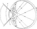
为便于理解该问题的解决方案,我们注意图1a和1b中的眼睛E,其中接触透镜L与现有技术的光纤环F一起保持在适当位置。要同时实现宽视场的成象和照明使设计者陷入困境,这可以从附图中看出。注意,角膜的直径约10毫米,眼睛的瞳孔、虹膜即使在扩张时也可能不超过4毫米。To facilitate understanding of the solution to this problem, we turn our attention to the eye E in Figures 1a and 1b, where a contact lens L is held in place with a fiber optic ring F of the prior art. Simultaneously achieving wide-field imaging and lighting puts designers in a bind, as can be seen in the accompanying drawings. Note that the diameter of the cornea is about 10 mm, and the pupil, iris of the eye may not exceed 4 mm even when dilated.
光学系统的入射光瞳(被中继时)设置在眼睛透镜处,以尽量减小象差和改进对散射光的阻碍;见图1a。接触透镜的最小直径和边缘倾斜度是由入射光瞳和到角膜的距离以及视场设定,如图1a所示。对于120度视场和1毫米直径入射光瞳的照相机而言,最小直径为6毫米,边缘倾斜度为40度。这样,光纤环F的半径必须设定为略大于例如7毫米,在该设计中,其导入角由该半径下的接触透镜L的倾斜度设定。The entrance pupil of the optical system (when relayed) is placed at the eye lens to minimize aberrations and improve rejection of scattered light; see Figure 1a. The minimum diameter and marginal inclination of a contact lens are set by the entrance pupil and distance from the cornea and field of view, as shown in Figure 1a. For a camera with a 120 degree field of view and a 1 mm diameter entrance pupil, the minimum diameter is 6 mm and the edge slope is 40 degrees. Thus, the radius of the fiber ring F must be set slightly larger than, say, 7 mm, and in this design its lead-in angle is set by the inclination of the contact lens L at this radius.
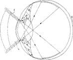
如图1b所示,一个显著的问题是,很难用设置在接触透镜L周边处的单光导环F获得眼睛E的中心处的照明。这是光纤的大引入角和小发散角所造成的。图中还示出,一部分光被眼睛透镜周边处的组织阻挡,进而决定被照明区域的尺寸。从光纤引入的光的发散角被其数值孔径限制。当与泪液接触时,光纤的发散角通常小于40度。这一问题无法通过加入第二个更大直径的光纤环来解决,尽管多个环可照亮更大的周边区域;这是现代光学设计法则的发现,与美国专利3,944,341的权利要求相抵触,可用于对实际眼睛的测量。如图1c所示,从更大直径的光纤环F1射出的光可能被眼睛虹膜阻挡。假定环直径为8毫米,眼睛虹膜直径为5.5毫米。因此,第二大光纤环F1只能帮助照明视网膜的周边区域,而无法照明中心区域。显然,人们需要能自由地设定照明指向和发散度,使其不受透镜直径和光纤材料的控制。A significant problem is that it is difficult to obtain illumination at the center of the eye E with a single light guide ring F placed at the periphery of the contact lens L, as shown in FIG. 1b. This is caused by the large introduction angle and small divergence angle of the fiber. It also shows that a portion of the light is blocked by tissue around the lens of the eye, which in turn determines the size of the illuminated area. The divergence angle of light introduced from an optical fiber is limited by its numerical aperture. When in contact with tear fluid, the divergence angle of the fiber is usually less than 40 degrees. This problem cannot be solved by adding a second fiber optic ring of larger diameter, although multiple rings can illuminate a larger peripheral area; this is a discovery of modern optical design laws that conflicts with the claims of US Patent 3,944,341, Can be used for measurements on actual eyes. As shown in Figure 1c, the light exiting the larger diameter fiber ring F1 may be blocked by the iris of the eye. Assume that the ring diameter is 8mm and the iris diameter of the eye is 5.5mm. Therefore, the second largest fiber optic ring F1 can only help to illuminate the peripheral area of the retina, but not the central area. Clearly, one needs to be able to freely set the pointing and divergence of the illumination independent of lens diameter and fiber material.
具体地说,很难将足够的光引导至视网膜的中心上。因此,需要另外考虑提供改进,用以将更多的光引向眼睛的中心。Specifically, it is difficult to direct enough light onto the center of the retina. Therefore, additional considerations are needed to provide improvements to direct more light towards the center of the eye.
因此,接触式宽视场照相机的设计者面临一个严重的困难。为了较宽的视场和将入射光瞳设置成最佳,照明环必须设置成一更大的半径,并且在该半径下,人的虹膜能够封住照亮视网膜中心所需要的部分。如果病人的虹膜没有扩张得足够大,则可以看到暗点。Designers of contact wide-field cameras therefore face a serious difficulty. For a wider field of view and optimal placement of the entrance pupil, the illumination ring must be set to a larger radius at which the human iris can enclose the portion needed to illuminate the center of the retina. If the patient's iris is not dilated enough, a scotoma may be seen.
概要summary
本发明的目的在于提供一种小型的、重量轻的、手持式图象俘获装置(ICU)。本发明的图象俘获装置接触视网膜、使瞳孔再成象、以最小的场曲度和最小的象差提供较宽的视场以及提供高保真的彩色成象。能够容纳在图象俘获装置内的小型三片式带电耦合器件(CCD)照相机的出现提高了图象的分辨率。It is an object of the present invention to provide a small, lightweight, hand-held image capture unit (ICU). The image capture device of the present invention contacts the retina, reimages the pupil, provides a wider field of view with minimal field curvature and minimal aberrations, and provides high fidelity color imaging. The advent of small three-chip charge-coupled device (CCD) cameras that can be housed within an image capture device has increased image resolution.
因此,本发明的一个具体目的是提供一种可在120度及更大范围内获得高质量彩色图象的宽视场成象装置,该装置具有非常均匀的图象强度、较低的反向散射和制造成本较低的设计。另一目的是减小所需要的扩张眼睛虹膜的最小直径,其减小的直径为5.5毫米,该数字在孩子中间是常见的。而且,本发明的一个目的是提供一种重量轻、可手持的成象装置。在另一实施例中,该成象装置允许各种血管照相用滤光器方便地拆装,并允许透镜方便地拆装。Accordingly, it is a specific object of the present invention to provide a wide field of view imaging device capable of obtaining high-quality color images at 120 degrees and beyond, which device has very uniform image intensity, low reverse Scattering and less expensive designs to manufacture. Another object is to reduce the minimum diameter of the iris of the dilated eye required, which is 5.5mm, which is a figure common among children. Furthermore, it is an object of the present invention to provide a light-weight, hand-held imaging device. In another embodiment, the imaging device allows easy attachment and removal of various angiography filters and allows easy removal and attachment of lenses.
本发明的一个具体目的是消除因使用光纤光导而引起的在使用宽视场接触照相机方面的经济和技术障碍。本发明是目的在于一种便携式图象俘获装置,它提供一种由机加工塑料或研磨抛光玻璃制成的一片式光导环。该光导的角度弯成使从眼睛透镜的反向反射达到最小,从而降低图象衬比度。使用一更大的接触透镜并将其设置在成象和照明光学元件之间以保护角膜,这样可大大提高系统的性能和制造性能。A specific object of the present invention is to eliminate the economic and technical barriers in the use of wide field of view contact cameras caused by the use of fiber optic light guides. The present invention is directed to a portable image capture device which provides a one piece light guide ring made of machined plastic or ground polished glass. The light guide is angled to minimize back reflection from the eye lens, thereby reducing image contrast. Using a larger contact lens and placing it between the imaging and illumination optics to protect the cornea greatly improves system performance and manufacturability.
本发明的另一特点是提供各种不同的改善,将更多的光从光导引导至眼睛视网膜的中心上。Another feature of the present invention is to provide various improvements to direct more light from the light guide onto the center of the retina of the eye.
其它的和进一步的目的、特点和优点将通过下面结合附图以揭示为目的对本发明目前的较佳实施例所进行的描述而变得清楚。Other and further objects, features and advantages will become apparent from the following description of presently preferred embodiments of the invention, which are taken for purposes of illustration when taken in conjunction with the accompanying drawings.
附图简述Brief description of the drawings
图1a是眼球处的一光学系统的侧向剖视图,表示较佳的中继入射光瞳的位置。Figure 1a is a side cross-sectional view of an optical system at the eyeball showing the preferred location of the relay entrance pupil.
图1b是眼球处的一光学系统的侧向剖视图,表示现有技术的照明限制。Figure 1b is a side sectional view of an optical system at the eyeball showing the illumination limitations of the prior art.
图1c是眼球处的一光学系统的侧向剖视图,表示现有技术中的多光纤环的照明限制。Figure 1c is a side sectional view of an optical system at the eyeball showing the illumination limitations of a prior art multi-fiber ring.
图2a是代替现有技术光纤的一光导的剖视图,表示眼泪和/或封装复合物会影响光导的正常工作。Figure 2a is a cross-sectional view of a light guide substituted for a prior art optical fiber, showing that tears and/or encapsulation compound can interfere with proper functioning of the light guide.
图2b是一光导的放大的局部剖视图,表示光通过端部的传递。Figure 2b is an enlarged fragmentary cross-sectional view of a light guide showing the transmission of light through the ends.
图3是本发明一实施例的前透镜装置的前透镜组的角膜接触透镜和双透镜以及光导的侧向剖视图。Fig. 3 is a side cross-sectional view of the contact lens and the double lens and the light guide of the front lens group of the front lens device according to an embodiment of the present invention.
图4是表示使用现有技术光纤的视场非常宽的系统如何会仅照亮视网膜的周边的剖视图。Figure 4 is a cross-sectional view showing how a very wide field of view system using prior art optical fibers would only illuminate the periphery of the retina.
图5a是本发明的可同时实现中心和周边照明的光学系统的侧向剖视图。Fig. 5a is a side cross-sectional view of the optical system capable of simultaneously realizing central and peripheral illumination according to the present invention.
图5b是用于阻挡因如图5a所示的中心照明而产生的从眼睛透镜的反向散射的光瞳罩的俯视图。Figure 5b is a top view of a pupil mask used to block backscatter from the eye lens due to central illumination as shown in Figure 5a.
图6是具有改善的中心照明的光学系统的另一实施例的侧向剖视图。6 is a side cross-sectional view of another embodiment of an optical system with improved central illumination.
图7是具有更大的中心照明的光学系统的另一实施例的侧向剖视图。7 is a side cross-sectional view of another embodiment of an optical system with greater central illumination.
图8是图7的实施例中所使用的菲涅尔透镜的放大剖视图。FIG. 8 is an enlarged cross-sectional view of a Fresnel lens used in the embodiment of FIG. 7 .
图9是本发明的图象俘获装置(ICU)的详细的侧向剖视图。Figure 9 is a detailed side sectional view of the image capture unit (ICU) of the present invention.
图10是该光学系统的剖视图。Fig. 10 is a sectional view of the optical system.
图11是该光学系统的剖视图,表示瞳孔、物体和图象的主光线和位置。Figure 11 is a cross-sectional view of the optical system showing the principal rays and positions of the pupil, object and image.
图12是眼睛前部的成象和照明系统的剖视图。Figure 12 is a cross-sectional view of the imaging and illumination system at the front of the eye.
较佳实施例详述DETAILED DESCRIPTION OF THE PREFERRED EMBODIMENT
如以上所讨论的,现有技术的光学系统具有很大的缺陷和限制。As discussed above, prior art optical systems have significant deficiencies and limitations.
作为本发明创造的一个出发点以及它的一部分,光导由诸如塑料或玻璃之类的透射性材料制成。可以使用任何合适的塑料,诸如丙烯酸酯或聚碳酸酯,并可以使用任何合适的玻璃,诸如具有高透射率(光谱从450毫微米到700毫微米)。如果光导被空气包围,从光导引入的光的发散角是可控制的,宽可以为180度。图2a中所示的原理性的送光装置设计成将光从一较大直径的光导管50集中到一围绕前透镜的小光导环。如图2b所示,可以将光导端部的形状制成和使光线弯折成以更佳的方向瞄准。然而,该项发明创造忽略了主要问题。首先,光导50的尖端51在接触角膜时是不合适的。第二,光导50的端部周围的空腔将是细菌可以栖身的地方,病人之间的交叉感染不可避免。第三,泪膜将充入该容积,由于泪膜的折射率接近大多数波导材料,因而,当光导由空气(折射率约等于1)围绕时所发生的光线在光导端部处的弯折几乎会被消除(泪膜的折射率接近1.34)。因此,暗点将重新出现在图象的中心。第四,眼睛虹膜的直径必须被扩张到大于6.5毫米,以防阻碍6毫米直径的光纤环。As a starting point of the invention and as part of it, the light guide is made of a transmissive material such as plastic or glass. Any suitable plastic may be used, such as acrylic or polycarbonate, and any suitable glass may be used, such as with high transmission (spectrum from 450 nm to 700 nm). If the light guide is surrounded by air, the divergence angle of the light introduced from the light guide is controllable and can be as wide as 180 degrees. The schematic light delivery arrangement shown in Figure 2a is designed to concentrate light from a larger diameter
为了用可实行的和可制造的器具来实现这一概念,我们将整个光导50置于一接触或角膜玻璃透镜24的后面,该透镜的直径大于积聚返回光的透镜25,如图3所示。该光学系统的入射光瞳也略微朝接触透镜移动,从而使透镜的直径减小到5毫米,进而使光导直径减小到6毫米。在本设计中,当眼睛瞳孔扩张到大于5毫米时,可以照亮120度的视场,而在图象的中心部分不会有暗点。从光导的相对侧发出的光线将在视网膜的中心附近重合,这将为该区域提供更可靠的照明。光强在视网膜上的分配也设计成从中心逐渐向周边减弱,这将使视网膜图象的光强分配更为均匀。现在,只需将“接触”玻璃的边界粘接于保护接触透镜后面的容积不被任何眼睛液体或粘结剂侵入的壳体上。In order to implement this concept with a practical and manufacturable instrument, we place the entire
尽管只示出了局部被切去以改变引入角的光导50及其伸展情况,但它还可以例如在尖端51上具有一小透镜的形状。接触透镜24不需要有任何光焦度,但也可以根据需要而设。只需要用粘结复合物将接触透镜24的边缘粘接于手持部10的壳体11。Although the
接触玻璃24的材料与泪液之间的折射率的差异尽管很小,但仍会造成从接触玻璃前表面发出的部分光线的偏向。虽然光导和成象系统被精心地设计成使偏向的光线无法直接到达带电耦合器件照相机,但它仍会造成很强的杂光,从而在形成暗物体状视网膜的象时降低图象质量。为了提高性能,可以在接触玻璃的前表面上加一层较硬的、耐用的、传统光学抗反射涂层。也可以采取其它措施来减少杂光,包括选择性地在光导的部分表面上施加吸收层、在成象系统中安装光挡。而且,接触透镜可以具有其它形状,包括可供前部双透镜插装的孔。双透镜的边缘被涂黑,使从光导进入接触透镜而行进的光线无法进入该前部双透镜。The difference in refractive index between the material of the
虽然上述设计提高了性能,但对于视场非常宽的成象仍存在一个限制。研究图4所示的情况,其中提供了一个非常宽的视场,它使前部成象透镜变得更宽。在这种情况下,因为受虹膜的阻挡,无论使用多少光圈或辅助导向措施都不可能照亮视网膜的中心和周边。While the above design improves performance, there is still a limitation for very wide field of view imaging. Consider the situation shown in Figure 4, which provides a very wide field of view, which makes the front imaging lens wider. In this case, it is impossible to illuminate the center and periphery of the retina no matter how many apertures or auxiliary guiding measures are used because of obstruction by the iris.
这些照明系统的问题可以由图5a的设计来解决。这里,既可用一中心光导,也可将一束光从光源14投射到成象光学系统,以照亮视网膜的中心部分,并使用标准光导来照亮周边部分。现在必须对付的是来自位于中心的光馈给的反向散射。这可以如图5b所示用一带中心遮挡部23的光瞳罩来解决,该瞳孔设置在位置31(图7)处。These lighting system problems can be solved by the design of Figure 5a. Here, either a central light guide can be used, or a beam of light can be projected from the light source 14 to the imaging optics to illuminate the central portion of the retina, and standard light guides can be used to illuminate the peripheral portions. Now one has to contend with backscatter from the centrally located light feed. This can be solved with a pupil mask with a
本发明还可以提供其它和进一步的实施例,其中相同的部件与图3和图5中的标号基本相同,只是增加了附缀“1”和“2”。在图3的实施例的一些应用场合中,在将足够的光线引导至眼睛E视网膜的中心上时遇到了困难。在该实施例中,光导50的端部51具有倾斜的切口,用于将光线引导通过接触透镜24并引向眼睛的中心。然而,在提供方向所必需的端部51的大倾角下,塑料光导50的偏向很高,射出端部51的光线量减少。(注意,所有电介质的反射率都会随入射角的增大而增大。)同样在图3的实施例中,角膜接触玻璃透镜24如图所示基本上没有光焦度,因为所示的透镜24在前侧和后侧具有相同的曲率半径。The present invention can also provide other and further embodiments, wherein the same parts have basically the same reference numerals as in Fig. 3 and Fig. 5, but with the addition of suffixes "1" and "2". In some applications of the embodiment of Fig. 3, difficulty is encountered in directing sufficient light onto the center of the retina of the eye E. In this embodiment, the
下面参见图6的实施例,角膜接触玻璃透镜124具有光焦度,以帮助将来自光导150端部151的光线朝眼睛E的中心方向引导。例如,透镜124可以是平凹式透镜,它具有稍平的背面101和中凹的正面102。同样,前部透镜125的第二部分103可以由与透镜124相同的玻璃制成,由于它接触透镜124的背面101,透镜124的背面101的光焦度在该光学系统中无关紧要。Referring now to the embodiment of FIG. 6, the contact glass lens 124 has optical power to help direct light from the end 151 of the light guide 150 toward the center of the eye E. Referring now to FIG. For example, lens 124 may be a plano-concave lens having a slightly flat back 101 and a concave front 102 . Likewise, the second portion 103 of the front lens 125 can be made of the same glass as the lens 124, since it contacts the back 101 of the lens 124, the power of the back 101 of the lens 124 is not important in this optical system.
图7和图8中示出了一更佳的实施例。甚至对于图6的实施例,由于透镜103上所需的斜面,光导150的端部151的出口点还要从光学系统的中心朝外移动。这是一个缺点,因为它需要被测量的人的瞳孔更大。在图7的实施例中,在光导250与角膜接触透镜224之间设置一附加的透镜205,用于额外地将光线导向眼睛E的中心。发现菲涅尔透镜(图8)是合适的。另外,光导250的端部251向下延伸而与附加透镜205相接触。例如,透镜205可以设置在光导250的端部251上。该实施例使光源点在物理上尽最大可能地朝内移动,它是一种制造起来相对较为便宜的设计。A more preferred embodiment is shown in FIGS. 7 and 8 . Even for the embodiment of FIG. 6 , due to the required slope on the lens 103 , the exit point of the end 151 of the light guide 150 is moved outward from the center of the optical system. This is a disadvantage because it requires the pupils of the person being measured to be larger. In the embodiment of FIG. 7, an
本发明提供一种宽视场图象俘获装置(ICU),它使用图3、5a、6和7的光导以获得通常在120到150度的非常宽的视场的高质量彩色图象。它重量轻,可以手持。但它也可以安装在裂隙灯之类的装置上,这对于能够配合的成年病人来说可能是一种理想的方法。本发明的图象俘获装置还允许方便地拆装各种血管照相用滤光器和/或改变视场用的不同的透镜或透镜组。而且,它配置成可以设置一透镜组用来使眼睛的前部成象。The present invention provides a wide field image capture unit (ICU) that uses the light guides of Figures 3, 5a, 6 and 7 to obtain high quality color images over a very wide field of view, typically 120 to 150 degrees. It is lightweight and can be hand held. But it can also be mounted on something like a slit lamp, which may be an ideal approach for adult patients who can cooperate. The image capture device of the present invention also allows easy attachment and removal of various filters for angiography and/or different lenses or lens groups for changing the field of view. Furthermore, it is configured such that a lens group is provided for imaging the front of the eye.
图6中示出了本发明的图象俘获装置的一较佳实施例。标号10总的表示本发明的图象俘获装置(ICU)。A preferred embodiment of the image capture device of the present invention is shown in FIG. 6 . Reference numeral 10 generally denotes an image capture unit (ICU) of the present invention.
该图象俘获装置具有一前壳体11和一后壳体12,它们可在接点16处分离,该接点通常可以例如是一锁合略微。后壳体12中设置有光纤功率供给接头17以及照相机和控制功能接头18,所有这些均揭示于1994年11月17日提交的、题为“眼睛成象系统”的专利申请No.08/340,976中,该申请援引在此供参考。该便携式图象俘获装置可以用手持来接触角膜。聚焦是通过一内部机构来实现,该机构可改变前部和后部透镜组之间的距离。或者,可在该图象俘获装置中安装一光源,从而不需要外部光供给光纤缆。The image capture device has a front housing 11 and a rear housing 12, which are separable at a joint 16, which may typically be, for example, a locking pin. Disposed in the rear housing 12 is a fiber optic power supply connection 17 and a camera and control
如图7和8中清楚示出的,总的由标号18表示的透镜系统被分成前部组和后部组,用于执行聚焦和瞳孔中继功能。前部透镜组20包括一前部双透镜25,其前表面上粘结有一较宽的接触或角膜透镜24,它们作为一三合透镜设置在系统中。随后的透镜是一双透镜26,然后是一单透镜27,该单透镜的后面跟有一弯月片23,该弯月片也可以是一非球面,这样就构成了前部透镜组。后部透镜组30是一双透镜31和一三合透镜32,用作防色彩差装置。并设置有一彩色带电耦合器件38,用以接收视网膜图象。As best shown in Figures 7 and 8, the lens system generally designated 18 is divided into front and rear groups for performing focusing and pupil relay functions. The
视网膜40是该光学系统的对象,它在图象位置42处被再成象,然后在图象平面位置44的照相机处被再成象。系统光瞳由一位于位置43处的罩子设定,但在入射光瞳位置41处被中继到眼睛透镜。The retina 40, the object of the optical system, is reimaged at image position 42 and then at the camera at image plane position 44. The system pupil is set by a mask at position 43 but is relayed to the eye lens at entrance pupil position 41 .
光导50围绕角膜接触透镜24,从而通过角膜而照亮眼睛,它具有一成形的尖端51。位置45处的一罩子设置一视场光阑,从而限定120度的视场并阻挡杂光。位置46处的一罩子设置一杂光挡,用以进一步阻挡从前部透镜反射的光。
图象俘获装置与构成眼睛成象装置的其它构件(包括记录设备硬件)之间的连接线缆包括一用于在图象俘获装置与其它构件之间供给和接收信息的控制线以及一用于为该图象俘获装置提供能量的电线,所有这些均揭示于专利申请08/340,976中。另外,如果图象俘获装置中不含有光源,则该控制线中可包含一光纤缆,用于从该俘获装置外部的光源提供光。The connection cable between the image capture device and other components (including recording device hardware) that make up the eye imaging device includes a control line for supplying and receiving information between the image capture device and other components, and a control line for The electrical wiring to power the image capture device, all of which are disclosed in patent application 08/340,976. Alternatively, if the image capture device does not contain a light source, the control line may include a fiber optic cable for providing light from a light source external to the capture device.
在本发明中,用一个一片式的实心环作为光导50。然而,为了组装方便,该光导50可包括延伸部分50a和50b,它们彼此邻接用于传输光线。尖端51的形状制成使光线弯折成所需的方向。在表面的选定部分上涂覆一光吸收层,以减少杂光。使用一由单片塑料或玻璃制成环状的透明光导有很大的好处。在现有技术中,光线从光纤的瞄准角是由光纤在角膜半径上的位置控制的,并在环的位置处垂直于角膜。In the present invention, a one-piece solid ring is used as the
在一个实施例中,光通过一光纤缆13输送到图象俘获装置10,该光纤缆容纳于连接线缆18中。光纤缆将光从该图象俘获装置外部的一整个成象装置的另一构件中的光源输送到该图象俘获装置。在另一实施例中,光源完全容纳于图象俘获装置10内。In one embodiment, light is delivered to image capture device 10 via a fiber optic cable 13 housed in
本发明为图象俘获装置10提供分体式的壳体11和12,从而允许更换前部透镜组20以适合不同尺寸和形状的眼睛。例如,与用在成人身上的角膜透镜24相比,婴儿所适用的角膜接触透镜24是不同的。而且,本发明的一个具体特点是,前部和后部透镜组20和30可以迅速和方便地更换或重新定位,以便插装用于不同荧光血管照相的滤光器70或可提供不同视场的透镜。图象俘获装置10的前、后部11和12之间的一简单接触件71就足以用于照明传送。分体式的壳体使得可以完全移去前部透镜组20,而单独使用后部透镜组30来使眼睛的前部成象。The present invention provides a split housing 11 and 12 for the image capture device 10, allowing the front lens set 20 to be replaced to suit eyes of different sizes and shapes. For example,
提供分体式壳体11的又一个优点是,如果移去前壳体,则可在其位置插装一个设计用来通过透镜61使眼睛前部成象的专用壳体60,如图9中清楚表示。已经送到后壳体的光可以被引导至一扩散器62,该扩散器进而能够为角膜成象提供照明。这样,视网膜照相机便可同时用作角膜成象器。Yet another advantage of providing a split housing 11 is that, if the front housing is removed, a special housing 60 designed to image the front of the eye through a lens 61 can be inserted in its place, as is clear in FIG. 9 express. Light that has been sent to the posterior housing can be directed to a
这些优点在一可实际制造的系统中提供;而这在本发明提出之前在商业上还无法实现。These advantages are provided in a practically manufacturable system; this was not commercially available prior to the present invention.
因此,可以用本发明来充分实现上述目的,并达到上述目标和优点以及本文所提到的其它目标和优点。虽然以揭示为目的提供了发明到目前为止的较佳实施例,但在不脱离发明精神和所附权利要求书范围的情况下是可以对零件结构和配置的细节进行许多变化的。The present invention, therefore, can be used to fully realize the above objects and to achieve the above objects and advantages as well as other objects and advantages mentioned herein. While the presently preferred embodiment of the invention has been provided for purposes of disclosure, many changes may be made in details of construction and arrangement of parts without departing from the spirit of the invention and the scope of the appended claims.
Claims (16)
Applications Claiming Priority (4)
| Application Number | Priority Date | Filing Date | Title |
|---|---|---|---|
| US68572596A | 1996-07-24 | 1996-07-24 | |
| US08/685,725 | 1996-07-24 | ||
| US08/820,224 | 1997-03-18 | ||
| US08/820,224US5822036A (en) | 1996-07-24 | 1997-03-18 | Eye imaging unit having a circular light guide |
Publications (2)
| Publication Number | Publication Date |
|---|---|
| CN1226143Atrue CN1226143A (en) | 1999-08-18 |
| CN1157152C CN1157152C (en) | 2004-07-14 |
Family
ID=27103665
Family Applications (1)
| Application Number | Title | Priority Date | Filing Date |
|---|---|---|---|
| CNB971967024AExpired - LifetimeCN1157152C (en) | 1996-07-24 | 1997-07-22 | Portable imaging capture unit for eye |
Country Status (13)
| Country | Link |
|---|---|
| US (1) | US5822036A (en) |
| EP (1) | EP0925013B1 (en) |
| JP (1) | JP4141503B2 (en) |
| CN (1) | CN1157152C (en) |
| AT (1) | ATE268563T1 (en) |
| AU (1) | AU3806897A (en) |
| CA (1) | CA2260800C (en) |
| DE (1) | DE69729459T2 (en) |
| DK (1) | DK0925013T3 (en) |
| ES (1) | ES2218694T3 (en) |
| PT (1) | PT925013E (en) |
| TW (1) | TW352334B (en) |
| WO (1) | WO1998003112A1 (en) |
Cited By (10)
| Publication number | Priority date | Publication date | Assignee | Title |
|---|---|---|---|---|
| CN100335008C (en)* | 2002-03-29 | 2007-09-05 | 松下电器产业株式会社 | Eye imaging device |
| CN101474061B (en)* | 2008-01-03 | 2011-07-20 | 北京宏仁凝瑞科技发展有限公司 | Contact type eyeground imaging system |
| CN102939043A (en)* | 2010-05-27 | 2013-02-20 | 詹弗兰科·帕苏埃洛 | Ophthalmic illumination device |
| CN104398236A (en)* | 2014-12-17 | 2015-03-11 | 天津市索维电子技术有限公司 | Large-field-of-view fundus imaging device |
| CN105451637A (en)* | 2013-03-17 | 2016-03-30 | 威盛纳斯医疗系统公司 | Wide field of view eye imaging device and related method |
| CN109414162A (en)* | 2016-05-13 | 2019-03-01 | 洛桑联邦理工学院 | For retinal absorption phase under oblique illumination and the system of dark-field imaging, method and apparatus |
| CN110251077A (en)* | 2019-01-30 | 2019-09-20 | 北京大学第三医院(北京大学第三临床医学院) | An ophthalmic photographing device and an ophthalmic photographing method |
| CN110974154A (en)* | 2019-10-31 | 2020-04-10 | 中山联合光电科技股份有限公司 | Contact type fundus camera lighting system |
| US20200329963A1 (en)* | 2014-07-02 | 2020-10-22 | Digital Diagnostics Inc. | Systems and methods for alignment of the eye for ocular imaging |
| CN115191927A (en)* | 2022-06-02 | 2022-10-18 | 北京理工大学 | A compact optical system for measuring human corneal curvature |
Families Citing this family (48)
| Publication number | Priority date | Publication date | Assignee | Title |
|---|---|---|---|---|
| US6012814A (en)* | 1998-05-28 | 2000-01-11 | University Of New Mexico | Extraocular muscle tester |
| DE29819341U1 (en)* | 1998-10-29 | 1999-03-04 | Oculus Optikgeräte GmbH, 35582 Wetzlar | Optical system for observing and photographing the inside of the eye |
| AUPQ762500A0 (en)* | 2000-05-19 | 2000-06-15 | Lions Eye Institute Limited | Portable slit lamp |
| US6361167B1 (en)* | 2000-06-13 | 2002-03-26 | Massie Research Laboratories, Inc. | Digital eye camera |
| US20030086064A1 (en)* | 2001-11-06 | 2003-05-08 | Sutter Erich E | Head mounted infrared fundus illuminator |
| WO2003039355A1 (en)* | 2001-11-07 | 2003-05-15 | Darren Rich | Gonioscopy assembly |
| JP2003279705A (en)* | 2002-03-25 | 2003-10-02 | Sanyo Electric Co Ltd | Antireflection member |
| ES2388037T3 (en)* | 2006-03-21 | 2012-10-05 | Freedom Scientific Inc. | Camera lighting for an electronic amplifier |
| US7621638B2 (en)* | 2006-11-29 | 2009-11-24 | Clarity Medical Systems, Inc. | Delivering a short Arc lamp light for eye imaging |
| DE102007014703A1 (en)* | 2007-03-23 | 2008-09-25 | Dieter Mann Gmbh | Diaphanoskopstab |
| WO2010011577A1 (en)* | 2008-07-19 | 2010-01-28 | Volk Donald A | Real image forming eye examination lens utilizing two reflecting surfaces with non-mirrored central viewing area |
| US8786520B2 (en)* | 2008-09-04 | 2014-07-22 | Innovega, Inc. | System and apparatus for display panels |
| US8070290B2 (en)* | 2008-12-17 | 2011-12-06 | Glaukos Corporation | Gonioscope for improved viewing |
| WO2010129775A1 (en) | 2009-05-06 | 2010-11-11 | University Of Virginia Patent Foundation | Self-illuminated handheld lens for retinal examination and photography and related method thereof |
| US8836778B2 (en) | 2009-12-04 | 2014-09-16 | Lumetrics, Inc. | Portable fundus camera |
| USD645490S1 (en) | 2009-12-16 | 2011-09-20 | Glaukos Corporation | Gonioscopic system including an optical element attachment |
| USD645489S1 (en) | 2009-12-16 | 2011-09-20 | Glaukos Corporation | Gonioscopic system including an optical element attachment |
| WO2012018991A2 (en) | 2010-08-05 | 2012-02-09 | Bioptigen, Inc. | Compact multimodality optical coherence tomography imaging systems and related methods and computer program products |
| US20150021228A1 (en) | 2012-02-02 | 2015-01-22 | Visunex Medical Systems Co., Ltd. | Eye imaging apparatus and systems |
| US9655517B2 (en) | 2012-02-02 | 2017-05-23 | Visunex Medical Systems Co. Ltd. | Portable eye imaging apparatus |
| US9351639B2 (en) | 2012-03-17 | 2016-05-31 | Visunex Medical Systems Co. Ltd. | Eye imaging apparatus with a wide field of view and related methods |
| US9615728B2 (en) | 2012-06-27 | 2017-04-11 | Camplex, Inc. | Surgical visualization system with camera tracking |
| US9642606B2 (en) | 2012-06-27 | 2017-05-09 | Camplex, Inc. | Surgical visualization system |
| US10179067B2 (en)* | 2012-10-25 | 2019-01-15 | The Regents Of The University Of Colorado | Adjustable loop fiber optic illumination device for surgery |
| USD717856S1 (en) | 2013-03-01 | 2014-11-18 | Welch Allyn, Inc. | Optical device adapter |
| US9782159B2 (en) | 2013-03-13 | 2017-10-10 | Camplex, Inc. | Surgical visualization systems |
| US9907698B2 (en)* | 2013-06-25 | 2018-03-06 | TECLens, LLC | Apparatus for phototherapy of the eye |
| US10028651B2 (en) | 2013-09-20 | 2018-07-24 | Camplex, Inc. | Surgical visualization systems and displays |
| EP3046458B1 (en) | 2013-09-20 | 2020-10-21 | Camplex, Inc. | Surgical visualization systems |
| US9986908B2 (en) | 2014-06-23 | 2018-06-05 | Visunex Medical Systems Co. Ltd. | Mechanical features of an eye imaging apparatus |
| EP3195592B1 (en) | 2014-09-14 | 2025-05-14 | Retivue Llc | Wide field fundus camera |
| JP6231724B2 (en) | 2014-09-26 | 2017-11-15 | ヴォルク オプティカル インコーポレイテッドVolk Optical Inc. | Ophthalmic lens assembly and assembly method |
| EP3226799A4 (en) | 2014-12-05 | 2018-07-25 | Camplex, Inc. | Surgical visualization systems and displays |
| CN107708524A (en) | 2015-01-26 | 2018-02-16 | 威盛纳斯医疗系统公司 | Disposable separation sleeve for eye imaging devices and associated method |
| US10499809B2 (en) | 2015-03-20 | 2019-12-10 | Glaukos Corporation | Gonioscopic devices |
| WO2016154589A1 (en) | 2015-03-25 | 2016-09-29 | Camplex, Inc. | Surgical visualization systems and displays |
| JP7075178B2 (en) | 2015-08-05 | 2022-05-25 | フェニックス テクノロジー グループ インコーポレイテッド | Wide-field retinal imager and how it works |
| WO2017091704A1 (en) | 2015-11-25 | 2017-06-01 | Camplex, Inc. | Surgical visualization systems and displays |
| GB201520983D0 (en)* | 2015-11-27 | 2016-01-13 | Univ Strathclyde | Imaging system and method |
| CN105662332A (en)* | 2016-04-13 | 2016-06-15 | 南京航空航天大学 | Wide-angle eye ground retina imaging device and method for annular illumination |
| US10925486B2 (en) | 2016-06-21 | 2021-02-23 | Retivue, Llc | Wide field fundus camera with auto-montage at a single alignment |
| US10674906B2 (en) | 2017-02-24 | 2020-06-09 | Glaukos Corporation | Gonioscopes |
| USD833008S1 (en) | 2017-02-27 | 2018-11-06 | Glaukos Corporation | Gonioscope |
| WO2018208691A1 (en) | 2017-05-08 | 2018-11-15 | Camplex, Inc. | Variable light source |
| JP7208997B2 (en)* | 2017-12-19 | 2023-01-19 | アルコン インコーポレイティド | Imaging multiple parts of the eye |
| CN120458494A (en) | 2018-10-13 | 2025-08-12 | 普瑞文塔医疗公司 | Illuminated contact lenses and systems for improved ocular diagnostics, disease management, and surgery |
| US11426071B2 (en)* | 2019-10-10 | 2022-08-30 | Natus Medical Incorporated | Eye-imaging system and apparatus |
| CN113509142B (en)* | 2021-06-07 | 2023-06-02 | 天津市索维电子技术有限公司 | Large-vision retina examination device |
Family Cites Families (13)
| Publication number | Priority date | Publication date | Assignee | Title |
|---|---|---|---|---|
| US3630602A (en)* | 1970-05-04 | 1971-12-28 | John Frederick Herbert | Contact lens |
| US3944341A (en)* | 1972-09-25 | 1976-03-16 | Retina Foundation | Wide-angle ophthalmoscope and fundus camera |
| US4200362A (en)* | 1972-09-25 | 1980-04-29 | Retina Foundation | Ophthalmoscope with uniform illumination |
| US3954329A (en)* | 1972-09-25 | 1976-05-04 | Retina Foundation | Wide-angle opthalmoscope employing transillumination |
| US4023189A (en)* | 1974-03-29 | 1977-05-10 | Varian Associates | Wide angle fundus illumination and photography apparatus |
| US4026638A (en)* | 1974-12-02 | 1977-05-31 | Varian Associates | Reduced glare scanner |
| DE2716614C3 (en)* | 1977-04-15 | 1980-10-16 | Fa. Carl Zeiss, 7920 Heidenheim | Optical system for imaging the retina |
| US4715703A (en)* | 1982-10-12 | 1987-12-29 | Rodenstock Instrument Corporation | Ocular-fundus analyzer |
| US4573778A (en)* | 1983-03-16 | 1986-03-04 | Boston University | Aqueous fluorophotometer |
| US5125730A (en)* | 1990-06-29 | 1992-06-30 | The United States Of America As Represented By The Administrator Of The National Aeronautics And Space Administration | Portable dynamic fundus instrument |
| DE4232280A1 (en)* | 1992-09-25 | 1994-03-31 | Optec Ges Fuer Optische Techni | Retina examination instrument with optical fibre illumination - has regulator on holder of ophthalmoscopic observation system for pressure on proximal light conductor end face on sclera |
| US5608472A (en)* | 1992-11-06 | 1997-03-04 | Research Development Foundation | Eye imaging system |
| US5537164A (en)* | 1994-12-20 | 1996-07-16 | Smith; Alan D. | Retroilluminating indirect gonioprism |
- 1997
- 1997-03-18USUS08/820,224patent/US5822036A/ennot_activeExpired - Lifetime
- 1997-06-14TWTW086108277Apatent/TW352334B/ennot_activeIP Right Cessation
- 1997-07-22AUAU38068/97Apatent/AU3806897A/ennot_activeAbandoned
- 1997-07-22JPJP50716198Apatent/JP4141503B2/ennot_activeExpired - Lifetime
- 1997-07-22WOPCT/US1997/012732patent/WO1998003112A1/enactiveIP Right Grant
- 1997-07-22DKDK97935037Tpatent/DK0925013T3/enactive
- 1997-07-22CNCNB971967024Apatent/CN1157152C/ennot_activeExpired - Lifetime
- 1997-07-22EPEP97935037Apatent/EP0925013B1/ennot_activeExpired - Lifetime
- 1997-07-22ATAT97935037Tpatent/ATE268563T1/enactive
- 1997-07-22ESES97935037Tpatent/ES2218694T3/ennot_activeExpired - Lifetime
- 1997-07-22PTPT97935037Tpatent/PT925013E/enunknown
- 1997-07-22DEDE69729459Tpatent/DE69729459T2/ennot_activeExpired - Lifetime
- 1997-07-22CACA002260800Apatent/CA2260800C/ennot_activeExpired - Lifetime
Cited By (17)
| Publication number | Priority date | Publication date | Assignee | Title |
|---|---|---|---|---|
| CN100335008C (en)* | 2002-03-29 | 2007-09-05 | 松下电器产业株式会社 | Eye imaging device |
| CN101474061B (en)* | 2008-01-03 | 2011-07-20 | 北京宏仁凝瑞科技发展有限公司 | Contact type eyeground imaging system |
| CN102939043B (en)* | 2010-05-27 | 2015-07-01 | 詹弗兰科·帕苏埃洛 | Ophthalmic illumination device |
| CN102939043A (en)* | 2010-05-27 | 2013-02-20 | 詹弗兰科·帕苏埃洛 | Ophthalmic illumination device |
| CN108113643A (en)* | 2013-03-17 | 2018-06-05 | 威盛纳斯医疗系统公司 | Wide visual field eye imaging devices and its correlation technique |
| CN105451637A (en)* | 2013-03-17 | 2016-03-30 | 威盛纳斯医疗系统公司 | Wide field of view eye imaging device and related method |
| CN108095684A (en)* | 2013-03-17 | 2018-06-01 | 威盛纳斯医疗系统公司 | Utilize the eye imaging devices of sequential illumination |
| CN108113642A (en)* | 2013-03-17 | 2018-06-05 | 威盛纳斯医疗系统公司 | Wide visual field eye imaging devices and its correlation technique |
| CN108245128A (en)* | 2013-03-17 | 2018-07-06 | 威盛纳斯医疗系统公司 | The eye imaging devices of hermetic seal |
| US20200329963A1 (en)* | 2014-07-02 | 2020-10-22 | Digital Diagnostics Inc. | Systems and methods for alignment of the eye for ocular imaging |
| US11903649B2 (en)* | 2014-07-02 | 2024-02-20 | Digital Diagnostics Inc. | Systems and methods for alignment of the eye for ocular imaging |
| CN104398236B (en)* | 2014-12-17 | 2015-12-16 | 天津市索维电子技术有限公司 | A kind of Large visual angle fundus imaging device |
| CN104398236A (en)* | 2014-12-17 | 2015-03-11 | 天津市索维电子技术有限公司 | Large-field-of-view fundus imaging device |
| CN109414162A (en)* | 2016-05-13 | 2019-03-01 | 洛桑联邦理工学院 | For retinal absorption phase under oblique illumination and the system of dark-field imaging, method and apparatus |
| CN110251077A (en)* | 2019-01-30 | 2019-09-20 | 北京大学第三医院(北京大学第三临床医学院) | An ophthalmic photographing device and an ophthalmic photographing method |
| CN110974154A (en)* | 2019-10-31 | 2020-04-10 | 中山联合光电科技股份有限公司 | Contact type fundus camera lighting system |
| CN115191927A (en)* | 2022-06-02 | 2022-10-18 | 北京理工大学 | A compact optical system for measuring human corneal curvature |
Also Published As
| Publication number | Publication date |
|---|---|
| ATE268563T1 (en) | 2004-06-15 |
| DE69729459T2 (en) | 2005-06-30 |
| ES2218694T3 (en) | 2004-11-16 |
| CA2260800A1 (en) | 1998-01-29 |
| CA2260800C (en) | 2005-01-04 |
| DK0925013T3 (en) | 2004-07-26 |
| EP0925013B1 (en) | 2004-06-09 |
| CN1157152C (en) | 2004-07-14 |
| US5822036A (en) | 1998-10-13 |
| AU3806897A (en) | 1998-02-10 |
| JP4141503B2 (en) | 2008-08-27 |
| JP2002500520A (en) | 2002-01-08 |
| PT925013E (en) | 2004-10-29 |
| EP0925013A1 (en) | 1999-06-30 |
| DE69729459D1 (en) | 2004-07-15 |
| TW352334B (en) | 1999-02-11 |
| EP0925013A4 (en) | 1999-12-08 |
| WO1998003112A1 (en) | 1998-01-29 |
Similar Documents
| Publication | Publication Date | Title |
|---|---|---|
| CN1226143A (en) | Portable Eye Nitrile Image Capture Device | |
| US11819271B2 (en) | Self-illuminated handheld lens for retinal examination and photography and related method thereof | |
| US9907468B2 (en) | Eye imaging apparatus with sequential illumination | |
| JP6483085B2 (en) | Wide-field eye imaging device | |
| US11857261B2 (en) | Eye-imaging system and apparatus with coordinated illuminator fibers having a skewed fiber angle | |
| US20100091244A1 (en) | Real image forming eye examination lens utilizing two reflecting surfaces with non-mirrored central viewing area | |
| US20180055351A1 (en) | Self-Illuminated Handheld Lens for Retinal Examination and Photography and Related Method thereof | |
| JP7388767B2 (en) | Endoscope | |
| WO2009094214A1 (en) | Real image forming eye examination lens utilizing two reflecting surfaces | |
| US10426340B2 (en) | Self-illuminated handheld lens for retinal examination and photography and related method thereof | |
| CN105662333A (en) | Portable wide-angle eye bottom imaging device and method | |
| CN211324947U (en) | Contact type fundus camera lighting system | |
| CN213097817U (en) | Handheld digital diagnostic system with replaceable lens | |
| CN110974154A (en) | Contact type fundus camera lighting system | |
| CN120168213A (en) | A light-feeding device and a light-feeding image display method | |
| KR200288834Y1 (en) | Optical apparatus for photographing eyeball capable of guiding eyeball | |
| KR20030087455A (en) | Optical apparatus for photographing eyeball capable of guiding eyeball |
Legal Events
| Date | Code | Title | Description |
|---|---|---|---|
| C06 | Publication | ||
| PB01 | Publication | ||
| C10 | Entry into substantive examination | ||
| SE01 | Entry into force of request for substantive examination | ||
| C14 | Grant of patent or utility model | ||
| GR01 | Patent grant | ||
| REG | Reference to a national code | Ref country code:HK Ref legal event code:GR Ref document number:1045283 Country of ref document:HK | |
| CX01 | Expiry of patent term | Granted publication date:20040714 | |
| CX01 | Expiry of patent term |