CN1222839C - Powder receiving container, powder discharge device and apparatus for image formation - Google Patents
Powder receiving container, powder discharge device and apparatus for image formationDownload PDFInfo
- Publication number
- CN1222839C CN1222839CCNB011013729ACN01101372ACN1222839CCN 1222839 CCN1222839 CCN 1222839CCN B011013729 ACNB011013729 ACN B011013729ACN 01101372 ACN01101372 ACN 01101372ACN 1222839 CCN1222839 CCN 1222839C
- Authority
- CN
- China
- Prior art keywords
- mentioned
- bag
- powder
- toner
- storage container
- Prior art date
- Legal status (The legal status is an assumption and is not a legal conclusion. Google has not performed a legal analysis and makes no representation as to the accuracy of the status listed.)
- Expired - Lifetime
Links
Images


Classifications
- G—PHYSICS
- G03—PHOTOGRAPHY; CINEMATOGRAPHY; ANALOGOUS TECHNIQUES USING WAVES OTHER THAN OPTICAL WAVES; ELECTROGRAPHY; HOLOGRAPHY
- G03G—ELECTROGRAPHY; ELECTROPHOTOGRAPHY; MAGNETOGRAPHY
- G03G15/00—Apparatus for electrographic processes using a charge pattern
- G03G15/06—Apparatus for electrographic processes using a charge pattern for developing
- G03G15/08—Apparatus for electrographic processes using a charge pattern for developing using a solid developer, e.g. powder developer
- B—PERFORMING OPERATIONS; TRANSPORTING
- B65—CONVEYING; PACKING; STORING; HANDLING THIN OR FILAMENTARY MATERIAL
- B65D—CONTAINERS FOR STORAGE OR TRANSPORT OF ARTICLES OR MATERIALS, e.g. BAGS, BARRELS, BOTTLES, BOXES, CANS, CARTONS, CRATES, DRUMS, JARS, TANKS, HOPPERS, FORWARDING CONTAINERS; ACCESSORIES, CLOSURES, OR FITTINGS THEREFOR; PACKAGING ELEMENTS; PACKAGES
- B65D77/00—Packages formed by enclosing articles or materials in preformed containers, e.g. boxes, cartons, sacks or bags
- B65D77/04—Articles or materials enclosed in two or more containers disposed one within another
- B65D77/06—Liquids or semi-liquids or other materials or articles enclosed in flexible containers disposed within rigid containers
- G—PHYSICS
- G03—PHOTOGRAPHY; CINEMATOGRAPHY; ANALOGOUS TECHNIQUES USING WAVES OTHER THAN OPTICAL WAVES; ELECTROGRAPHY; HOLOGRAPHY
- G03G—ELECTROGRAPHY; ELECTROPHOTOGRAPHY; MAGNETOGRAPHY
- G03G15/00—Apparatus for electrographic processes using a charge pattern
- G03G15/06—Apparatus for electrographic processes using a charge pattern for developing
- G03G15/08—Apparatus for electrographic processes using a charge pattern for developing using a solid developer, e.g. powder developer
- G03G15/0822—Arrangements for preparing, mixing, supplying or dispensing developer
- G03G15/0848—Arrangements for testing or measuring developer properties or quality, e.g. charge, size, flowability
- G03G15/0849—Detection or control means for the developer concentration
- G03G15/0855—Detection or control means for the developer concentration the concentration being measured by optical means
- G—PHYSICS
- G03—PHOTOGRAPHY; CINEMATOGRAPHY; ANALOGOUS TECHNIQUES USING WAVES OTHER THAN OPTICAL WAVES; ELECTROGRAPHY; HOLOGRAPHY
- G03G—ELECTROGRAPHY; ELECTROPHOTOGRAPHY; MAGNETOGRAPHY
- G03G15/00—Apparatus for electrographic processes using a charge pattern
- G03G15/06—Apparatus for electrographic processes using a charge pattern for developing
- G03G15/08—Apparatus for electrographic processes using a charge pattern for developing using a solid developer, e.g. powder developer
- G03G15/0822—Arrangements for preparing, mixing, supplying or dispensing developer
- G03G15/0865—Arrangements for supplying new developer
- G03G15/0874—Arrangements for supplying new developer non-rigid containers, e.g. foldable cartridges, bags
- G—PHYSICS
- G03—PHOTOGRAPHY; CINEMATOGRAPHY; ANALOGOUS TECHNIQUES USING WAVES OTHER THAN OPTICAL WAVES; ELECTROGRAPHY; HOLOGRAPHY
- G03G—ELECTROGRAPHY; ELECTROPHOTOGRAPHY; MAGNETOGRAPHY
- G03G2215/00—Apparatus for electrophotographic processes
- G03G2215/06—Developing structures, details
- G03G2215/066—Toner cartridge or other attachable and detachable container for supplying developer material to replace the used material
- G03G2215/068—Toner cartridge or other attachable and detachable container for supplying developer material to replace the used material having a box like shape
- G—PHYSICS
- G03—PHOTOGRAPHY; CINEMATOGRAPHY; ANALOGOUS TECHNIQUES USING WAVES OTHER THAN OPTICAL WAVES; ELECTROGRAPHY; HOLOGRAPHY
- G03G—ELECTROGRAPHY; ELECTROPHOTOGRAPHY; MAGNETOGRAPHY
- G03G2215/00—Apparatus for electrophotographic processes
- G03G2215/06—Developing structures, details
- G03G2215/066—Toner cartridge or other attachable and detachable container for supplying developer material to replace the used material
- G03G2215/0682—Bag-type non-rigid container
- Y—GENERAL TAGGING OF NEW TECHNOLOGICAL DEVELOPMENTS; GENERAL TAGGING OF CROSS-SECTIONAL TECHNOLOGIES SPANNING OVER SEVERAL SECTIONS OF THE IPC; TECHNICAL SUBJECTS COVERED BY FORMER USPC CROSS-REFERENCE ART COLLECTIONS [XRACs] AND DIGESTS
- Y10—TECHNICAL SUBJECTS COVERED BY FORMER USPC
- Y10S—TECHNICAL SUBJECTS COVERED BY FORMER USPC CROSS-REFERENCE ART COLLECTIONS [XRACs] AND DIGESTS
- Y10S222/00—Dispensing
- Y10S222/01—Xerography
Landscapes
- Physics & Mathematics (AREA)
- General Physics & Mathematics (AREA)
- Engineering & Computer Science (AREA)
- Mechanical Engineering (AREA)
- Dry Development In Electrophotography (AREA)
- Packages (AREA)
- Bag Frames (AREA)
- Ink Jet (AREA)
Abstract
Translated fromChinese
Description
Translated fromChinese技术领域technical field
本发明涉及粉体收纳容器,粉体排出装置及图像形成装置,尤其涉及收纳在电子照相方式的图像形成装置中使用的作为着色剂的粉状墨粉的收纳容器、排出该墨粉的装置以及使用该粉体收纳容器、粉体排出装置的例如打印机、复印机、传真机等图像形成装置。The present invention relates to a powder storage container, a powder discharge device and an image forming device, and more particularly to a storage container for storing powdery toner as a colorant used in an electrophotographic image forming device, a device for discharging the toner, and Image forming apparatuses such as printers, copiers, and facsimiles using the powder storage container and powder discharge device.
背景技术Background technique
以往,收纳粉体墨粉的墨粉收纳容器由于使用盒、瓶等硬容器,更换墨粉收纳容器后,废弃使用容器上存在很大课题。厂家从用户处回收使用完的墨粉收纳容器,进行再生、再利用、焚烧处理,随着容器容量增大,涉及回收的流通成本高。因此,以往提出过能减容积的墨粉收纳容器的方案。Conventionally, hard containers such as cartridges and bottles have been used for toner storage containers for storing powder toner. After the toner storage container is replaced, there is a big problem in disposing of the used container. Manufacturers collect used toner storage containers from users for regeneration, reuse, and incineration. As the container capacity increases, the circulation cost involved in recycling is high. Therefore, conventionally, a volume-reduced toner storage container has been proposed.
但是,使用墨粉补给装置从该能减容积的墨粉收纳容器进行补给时,不能稳定地保持补给性能。另外,还提出过仅在运输时能减容积的墨粉收纳容器的方案,但当将墨粉移换到硬瓶或墨粉料斗时,不能解决墨粉飞散等引起的污染等问题,没有达到实用化阶段。However, when the toner replenishment device is used to replenish the toner container from the volume-reducible toner container, the replenishment performance cannot be maintained stably. In addition, a toner storage container that can reduce the volume only during transportation has been proposed, but when the toner is transferred to a hard bottle or a toner hopper, the problem of pollution caused by toner scattering cannot be solved, and it has not been achieved. practical stage.
本发明申请人已经提出过一种墨粉补给装置,即使使用由树脂、纸等挠性材形成的能减容积的墨粉收纳容器,也能稳定地保持补给性能,而且,能向与该容器分离的显影装置补给墨粉。The applicant of the present invention has already proposed a toner replenishing device that can stably maintain replenishment performance even if a toner storage container that can be reduced in volume formed by a flexible material such as resin or paper is used, and can supply the toner with the container. The separate developing unit replenishes toner.
在上述墨粉补给装置中,墨粉收纳容器以墨粉排出口朝下的竖立状态使用。这时,墨粉收纳容器的袋体有挠性,因自身重量等原因搭拉下来,堵塞墨粉排出口,若墨粉排出某数量以上,因折皱等夹持墨粉,会发生残留墨粉增多等问题。In the toner supply device described above, the toner storage container is used in an upright state with the toner discharge port facing downward. At this time, the bag body of the toner storage container is flexible, and it is pulled down due to its own weight, etc., and the toner discharge port is blocked. issues such as increase.
发明内容Contents of the invention
本发明就是鉴于上述先有技术所存在的问题而提出来的,本发明的目的在于,提供即使竖立使用也不易因挠性而歪斜的粉体收纳容器,使用该容器的粉体排出装置以及图像形成装置。The present invention is made in view of the above-mentioned problems in the prior art, and the object of the present invention is to provide a powder storage container that is not easily distorted due to flexibility even if it is used upright, a powder discharge device using the container, and an image forming device.
本发明的另一个目的在于,提供能减轻因压曲而引起粉体排出性恶化及多量残留粉体的粉体收纳容器以及使用该容器的图像形成装置。Another object of the present invention is to provide a powder storage container capable of reducing the deterioration of powder discharge performance and a large amount of residual powder due to buckling, and an image forming apparatus using the container.
为了实现上述目的,本发明提出一种粉体收纳容器,其特征在于,包括收纳粉体的可变形的袋体以及保持该袋体姿势的机构。In order to achieve the above object, the present invention proposes a powder storage container, which is characterized by comprising a deformable bag for storing powder and a mechanism for maintaining the posture of the bag.
根据本发明的粉体收纳容器,其特征还在于,上述袋体设有用于排出所收纳粉体的粉体排出口,同时,朝着该粉体排出口形成前端细的形状。The powder storage container according to the present invention is further characterized in that the bag body is provided with a powder outlet for discharging the stored powder, and is formed into a shape that is tapered toward the powder outlet.
根据本发明的粉体收纳容器,其特征还在于,上述姿势保持机构保持使上述粉体排出口朝下方处于直立状态的袋体的姿势。The powder storage container according to the present invention is further characterized in that the posture maintaining mechanism maintains the posture of the bag in an upright state with the powder discharge port facing downward.
根据本发明的粉体收纳容器,其特征还在于,上述姿势保持机构设有通过刚性保持袋体姿势的姿势保持部件。The powder storage container according to the present invention is further characterized in that the posture maintaining mechanism includes a posture maintaining member for rigidly maintaining the posture of the bag body.
根据本发明的粉体收纳容器,其特征还在于,上述姿势保持部件是立设在上述袋体外侧面的支撑部件。The powder storage container according to the present invention is further characterized in that the posture maintaining member is a supporting member erected on the outer surface of the bag.
根据本发明的粉体收纳容器,其特征还在于,上述姿势保持部件是大致围住上述袋体全周的形成为箱形的外箱部件。The powder storage container according to the present invention is further characterized in that the posture maintaining member is an outer case member formed in a box shape substantially surrounding the entire circumference of the bag.
根据本发明的粉体收纳容器,其特征还在于,上述姿势保持部件是立设在上述袋体内部的立设部件。The powder storage container according to the present invention is further characterized in that the posture maintaining member is an erecting member erected inside the bag body.
根据本发明的粉体收纳容器,其特征还在于,上述姿势保持机构是粘结在上述袋体上的粘结部件。The powder storage container according to the present invention is further characterized in that the posture maintaining mechanism is an adhesive member adhered to the bag body.
根据本发明的粉体收纳容器,其特征还在于,上述姿势保持机构是在上述袋体本身上成形的厚壁部。The powder storage container according to the present invention is further characterized in that the posture maintaining mechanism is a thick-walled portion formed on the bag body itself.
根据本发明的粉体收纳容器,其特征还在于,上述姿势保持机构是吊挂上述袋体的吊挂部件。The powder storage container according to the present invention is further characterized in that the posture maintaining mechanism is a hanging member for hanging the bag body.
根据本发明的粉体收纳容器,其特征还在于,上述姿势保持机构是设于上述袋体上可充填流体的流体袋。The powder storage container according to the present invention is further characterized in that the posture maintaining mechanism is a fluid bag provided on the bag body and can be filled with fluid.
根据本发明的粉体收纳容器,其特征还在于,可以利用供给到上述袋体内的气体执行上述姿势保持机构的功能。The powder storage container according to the present invention is further characterized in that the function of the posture maintaining mechanism can be performed by the gas supplied into the bag.
为了实现上述目的,本发明提出另一种粉体收纳容器,设有将所收纳粉体排出的排出部,其特征在于,以可变形的袋体构成,上述排出部通过尖细形状设置,收纳粉体,将上述排出部设于下侧,且固定排出部立设场合,设有减轻压曲机构,用于减轻在上述尖细形状部分发生的压曲。In order to achieve the above object, the present invention proposes another powder storage container, which is provided with a discharge part for discharging the stored powder. For powder, when the above-mentioned discharge part is provided on the lower side, and when the fixed discharge part is installed upright, a buckling reducing mechanism is provided to reduce the buckling that occurs in the above-mentioned tapered part.
根据本发明的粉体收纳容器,其特征还在于,上述减轻压曲机构设在上述袋体上。The powder storage container according to the present invention is further characterized in that the buckling reduction mechanism is provided on the bag body.
根据本发明的粉体收纳容器,其特征还在于,上述减轻压曲机构是设于上述袋体的尖细形状部分的脚状辅助片。The powder storage container according to the present invention is further characterized in that the buckling reducing means is a foot-shaped auxiliary piece provided on a tapered portion of the bag body.
根据本发明的粉体收纳容器,其特征还在于,上述辅助片是在制袋时在该袋体的尖细形状部分形成的剩余片。The powder storage container according to the present invention is further characterized in that the auxiliary sheet is an excess sheet formed on a tapered portion of the bag body during bag making.
根据本发明的粉体收纳容器,其特征还在于,对上述辅助片的大致全区域施以热封加工。The powder storage container according to the present invention is further characterized in that substantially the entire area of the auxiliary sheet is heat-sealed.
根据本发明的粉体收纳容器,其特征还在于,上述袋体收纳在比该袋体刚性大的外容器体内。The powder storage container according to the present invention is further characterized in that the bag body is housed in an outer container body that is more rigid than the bag body.
根据本发明的粉体收纳容器,其特征还在于,上述减轻压曲机构设在上述外容器体上。The powder storage container according to the present invention is further characterized in that the buckling reduction mechanism is provided on the outer container body.
根据本发明的粉体收纳容器,其特征还在于,上述减轻压曲机构是止滑部件,在上述外容器体的与上述袋体对向的面与该袋体相接。The powder storage container according to the present invention is further characterized in that the buckling reducing mechanism is an anti-slip member, and is in contact with the bag body on a surface of the outer container body that faces the bag body.
根据本发明的粉体收纳容器,其特征还在于,上述止滑部件呈棱状,朝粉体排出方向的垂直方向延伸,至少一个棱状止滑部件设在接近上述倾斜部的地方。The powder storage container according to the present invention is further characterized in that the anti-slip member is prismatic and extends in a direction perpendicular to the powder discharge direction, and at least one prismatic anti-slip member is provided close to the inclined portion.
根据本发明的粉体收纳容器,其特征还在于,上述上滑部件的至少与袋体相接的面的静摩擦系数大于或等于2.5。The powder storage container according to the present invention is further characterized in that the static friction coefficient of at least the surface of the above-mentioned sliding member in contact with the bag body is greater than or equal to 2.5.
根据本发明的粉体收纳容器,其特征还在于,上述袋体排出部的相反侧端面两端形成折入部,上述减轻压曲机构是插入部件,其设在上述外容器体上,且插入上述折入部的至少一方。The powder storage container according to the present invention is further characterized in that folded portions are formed at both ends of the opposite end surface of the discharge portion of the bag body, and the buckling relief mechanism is an insertion member provided on the outer container body and inserted into the At least one side of the fold-in portion.
根据本发明的粉体收纳容器,其特征还在于,上述插入部件设在插入上述袋体后关闭的上述外容器体的侧板上。The powder storage container according to the present invention is further characterized in that the insertion member is provided on a side plate of the outer container body that is closed after being inserted into the bag body.
根据本发明的粉体收纳容器,其特征还在于,至少在上述袋体的侧部设置热封部,上述减轻压曲机构以上述外容器体夹持该热封部。The powder storage container according to the present invention is further characterized in that a heat-sealed portion is provided at least on a side portion of the bag body, and the buckling reduction mechanism sandwiches the heat-sealed portion with the outer container body.
根据本发明的粉体收纳容器,其特征还在于,在插入上述袋体后关闭的上述外容器体的侧板上设有夹持部件,用于以上述外容器体夹持该热封部。The powder storage container according to the present invention is further characterized in that a clamping member is provided on the side plate of the outer container body which is closed after being inserted into the bag body, for clamping the heat-sealed part by the outer container body.
根据本发明的粉体收纳容器,其特征还在于,通过粘结将上述插入部件或夹持部件固定在上述外容器体上。The powder storage container according to the present invention is further characterized in that the insertion member or the clamping member is fixed to the outer container body by bonding.
根据本发明的粉体收纳容器,其特征还在于,上述减轻压曲机构是缓冲体,其嵌装在上述外容器体与袋体之间形成的间隙中。The powder storage container according to the present invention is further characterized in that the buckling reduction mechanism is a buffer body fitted in a gap formed between the outer container body and the bag body.
根据本发明的粉体收纳容器,其特征还在于,上述缓冲体预先粘结在上述外容器体上。The powder storage container according to the present invention is further characterized in that the buffer body is bonded to the outer container body in advance.
根据本发明的粉体收纳容器,其特征还在于,在上述袋体中收纳粉体。The powder storage container according to the present invention is further characterized by storing powder in the bag.
为了实现上述目的,本发明提出一种图像形成装置,其特征在于,使用在上述本发明所述的粉体收纳容器设置在图像形成装置本体中,在上述袋体中收纳粉体着色剂,使用所收纳的粉体着色剂供给显影装置形成图像。In order to achieve the above object, the present invention proposes an image forming device, which is characterized in that the powder storage container described in the present invention is set in the main body of the image forming device, the powder colorant is stored in the bag, and used The stored powder toner is supplied to a developing device to form an image.
为了实现上述目的,本发明提出一种粉体排出装置,从排出口排出收纳在粉体收纳容器内的粉体着色剂,其特征在于,上述粉体收纳容器设有收纳粉体的可变形袋体、保持该袋体姿势的机构以及设置上述袋体的设置部,使气体流入上述袋体内,使所收纳的粉体着色剂流动,同时,通过流入气体与上述姿势保持机构的作用,保持上述袋体姿势。In order to achieve the above object, the present invention proposes a powder discharge device that discharges the powder coloring agent stored in the powder storage container from the discharge port, wherein the powder storage container is provided with a deformable bag for storing powder Body, the mechanism for maintaining the posture of the bag body, and the installation part for setting the above-mentioned bag body, let the gas flow into the above-mentioned bag body, make the powder colorant contained flow, and at the same time, maintain the above-mentioned Bag pose.
根据本发明的粉体收纳容器,其特征还在于,上述姿势保持机构设在上述袋体上。The powder storage container according to the present invention is further characterized in that the posture maintaining mechanism is provided on the bag body.
根据本发明的粉体收纳容器,其特征还在于,上述姿势保持机构设在设置上述袋体的设置部侧。The powder storage container according to the present invention is further characterized in that the posture maintaining mechanism is provided on the installation portion side where the bag is installed.
根据本发明的粉体收纳容器,其特征还在于,流入上述袋体内的气体量比出粉体着色剂时流出量多。The powder storage container according to the present invention is further characterized in that the amount of gas flowing into the bag is larger than the amount of gas flowing out when the powder colorant is discharged.
根据本发明的粉体收纳容器,其特征还在于,设有调整上述袋体内压的机构。The powder storage container according to the present invention is further characterized in that it is provided with a mechanism for adjusting the inner pressure of the bag.
根据本发明的粉体收纳容器,其特征还在于,流入上述袋体内的气体被设定为与上述调整内压机构的调整量相对应的上述袋体膨起的量。The powder storage container according to the present invention is further characterized in that the gas flowing into the bag is set to an amount inflated by the bag corresponding to the adjustment amount of the internal pressure adjustment mechanism.
根据本发明的粉体收纳容器,其特征还在于,上述调整内压机构是过滤部件,不通过所收纳的粉体着色剂,而排出流入气体。The powder storage container according to the present invention is further characterized in that the internal pressure adjustment means is a filter member that discharges the inflow gas without passing the stored powder coloring agent.
根据本发明的粉体收纳容器,其特征还在于,设有上述本发明所述的粉体排出装置,通过该粉体排出装置将从上述粉体收纳容器中排出的粉体着色剂送向显影装置。According to the powder storage container of the present invention, it is also characterized in that it is provided with the above-mentioned powder discharge device of the present invention, and the powder colorant discharged from the powder storage container is sent to the developer through the powder discharge device. device.
下面说明本发明的效果。Effects of the present invention will be described below.
按照本发明的粉体收纳容器、粉体排出装置以及图像形成装置,粉体收纳容器的袋体即使可变形,在设置时也能防止歪斜,能可靠防止残留多量墨粉,防止因歪斜引起袋体破损等。另外,若并用通过部件刚性等实现的姿势保持机构及通过将气体供给容器内实现的姿势保持机构,能更可靠地防止容器歪斜。According to the powder storage container, powder discharge device, and image forming apparatus of the present invention, even if the bag body of the powder storage container is deformable, it can prevent skewing during installation, reliably prevent a large amount of toner from remaining, and prevent the bag body from being deformed due to skewing. body damage etc. In addition, if the posture maintaining mechanism realized by member rigidity and the posture maintaining mechanism realized by supplying gas into the container are used in combination, it is possible to more reliably prevent the container from being skewed.
按照本发明的粉体收纳容器、粉体排出装置以及图像形成装置,能对粉体收纳容器进行调整,供给粉体收纳容器的空气限制得到缓和,能供给大量空气,因此,粉体能得到充分搅拌。According to the powder storage container, powder discharge device, and image forming apparatus of the present invention, the powder storage container can be adjusted, the restriction of the air supplied to the powder storage container is relaxed, and a large amount of air can be supplied, so the powder can be fully obtained. Stir.
按照本发明的粉体收纳容器、粉体排出装置以及图像形成装置,即使是可变形的、排出部侧为尖细形状的袋体,也能减轻在该尖细形状部分发生的压曲。According to the powder storage container, powder discharge device, and image forming apparatus of the present invention, even if the pouch is deformable and has a tapered shape on the discharge portion side, buckling occurring at the tapered portion can be reduced.
按照本发明的粉体收纳容器、粉体排出装置以及图像形成装置,减轻压曲机构设在袋体上,能减轻仅由袋体构成的粉体收纳容器的压曲。若以在制袋时形成的剩余片构成辅助片,能以廉价结构实现适当强度。According to the powder storage container, powder discharge device, and image forming apparatus of the present invention, the buckling reducing mechanism is provided on the bag body, so that the buckling of the powder storage container composed only of the bag body can be reduced. If the auxiliary sheet is constituted by an excess sheet formed during bag making, appropriate strength can be achieved with an inexpensive structure.
按照本发明的粉体收纳容器、粉体排出装置以及图像形成装置,通过设在外收纳体的减轻压曲机构,能减轻袋体压曲。According to the powder storage container, powder discharge device, and image forming apparatus of the present invention, bag buckling can be reduced by the buckling reduction mechanism provided on the outer storage body.
附图说明Description of drawings
附图简要说明如下:A brief description of the accompanying drawings is as follows:
图1是本发明涉及的图像形成装置的墨粉补给机构的结构图;FIG. 1 is a structural diagram of a toner replenishing mechanism of an image forming apparatus according to the present invention;
图2是从粉体收纳容器上方看的斜视图;Fig. 2 is a perspective view viewed from above the powder storage container;
图3是从粉体收纳容器下方看的斜视图;Fig. 3 is a perspective view seen from the bottom of the powder storage container;
图4是表示本发明粉体收纳容器第一实施例的截面说明图;Fig. 4 is a cross-sectional explanatory view showing the first embodiment of the powder storage container of the present invention;
图5是表示该实施例的外箱体的斜视图;Fig. 5 is a perspective view showing the outer box of this embodiment;
图6是表示本发明粉体收纳容器第二实施例的斜视图;Fig. 6 is a perspective view showing a second embodiment of the powder storage container of the present invention;
图7是表示本发明粉体收纳容器的接口部的正面图;Fig. 7 is a front view showing the interface portion of the powder storage container of the present invention;
图8是图7的VIII-VIII线剖视图;Fig. 8 is the VIII-VIII line sectional view of Fig. 7;
图9是图7的IX-IX线剖视图;Fig. 9 is a sectional view of line IX-IX of Fig. 7;
图10是图6的粉体收纳容器的变型例的斜视图;Fig. 10 is a perspective view of a modified example of the powder storage container of Fig. 6;
图11是表示本发明粉体收纳容器第三实施例的斜视图;Fig. 11 is a perspective view showing a third embodiment of the powder storage container of the present invention;
图12是图11的粉体收纳容器的变型例的斜视图;Fig. 12 is a perspective view of a modified example of the powder storage container of Fig. 11;
图13是表示本发明粉体收纳容器第四实施例的斜视图;Fig. 13 is a perspective view showing a fourth embodiment of the powder storage container of the present invention;
图14是表示本发明粉体收纳容器第五实施例的斜视图;Fig. 14 is a perspective view showing a fifth embodiment of the powder storage container of the present invention;
图15是表示本发明粉体收纳容器第六实施例的斜视图;Fig. 15 is a perspective view showing a sixth embodiment of the powder storage container of the present invention;
图16是表示本发明涉及的粉体收纳容器一例的斜视图;Fig. 16 is a perspective view showing an example of a powder storage container according to the present invention;
图17是表示将该容器的粉体袋收纳在外箱体中状态的说明图;Fig. 17 is an explanatory diagram showing a state in which the powder bag of the container is housed in the outer box;
图18是表示该容器的墨粉袋被压曲状态的说明图;Fig. 18 is an explanatory view showing a buckled state of the toner bag of the container;
图19是表示本发明粉体收纳容器第七实施例的斜视图;Fig. 19 is a perspective view showing a seventh embodiment of the powder storage container of the present invention;
图20是图19的容器的变型例的说明图;Fig. 20 is an explanatory diagram of a modification of the container of Fig. 19;
图21是表示止滑部件一例的放大说明图;Fig. 21 is an enlarged explanatory view showing an example of an anti-slip member;
图22是表示本发明粉体收纳容器第八实施例的斜视图;Fig. 22 is a perspective view showing the eighth embodiment of the powder storage container of the present invention;
图23是图22的粉体收纳容器的截面说明图;Fig. 23 is a cross-sectional explanatory view of the powder storage container of Fig. 22;
图24是图22的容器的变型例的说明图;Fig. 24 is an explanatory diagram of a modification of the container of Fig. 22;
图25是表示本发明粉体收纳容器第九实施例的斜视图;Fig. 25 is a perspective view showing a ninth embodiment of the powder storage container of the present invention;
图26是表示本发明粉体收纳容器第十实施例的斜视图;Fig. 26 is a perspective view showing a tenth embodiment of the powder storage container of the present invention;
图27涉及本发明粉体收纳容器第十一实施例,是从下看粉体收纳容器的斜视图;Fig. 27 relates to the eleventh embodiment of the powder storage container of the present invention, which is a perspective view of the powder storage container from below;
图28是表示图27的粉体收纳容器使用状态的说明图;Fig. 28 is an explanatory view showing the state of use of the powder storage container of Fig. 27;
图29是制作图27的粉体收纳容器时的说明图;Fig. 29 is an explanatory diagram when manufacturing the powder storage container of Fig. 27;
图30是使用本发明涉及的粉体收纳容器的墨粉补给机构的截面说明图。30 is a cross-sectional explanatory view of a toner supply mechanism using the powder storage container according to the present invention.
具体实施方式Detailed ways
下面参照附图,详细说明本发明实施例。Embodiments of the present invention will be described in detail below with reference to the accompanying drawings.
图1表示本发明涉及的图像形成装置的墨粉补给装置一例的结构图。FIG. 1 is a block diagram showing an example of a toner replenishing device of an image forming apparatus according to the present invention.
在图1中,符号1表示显影装置,20表示作为墨粉收纳容器构成的粉体收纳容器,其中收纳作为着色剂的粉体墨粉。In FIG. 1 , reference numeral 1 denotes a developing device, and 20 denotes a powder storage container configured as a toner storage container in which powdery toner as a colorant is stored.
墨粉收纳容器20作为与显影装置1分开的另一个组件构成,装于图像形成装置本体的设置位置。墨粉收纳容器20的设置位置可以是打开图像形成装置本体的门或罩等时露出的装置内部侧的位置,也可以是装置外部的位置。The
图2是从墨粉收纳容器上方看的斜视图,图3是从墨粉收纳容器下方看的斜视图。FIG. 2 is a perspective view seen from above the toner storage container, and FIG. 3 is a perspective view seen from the bottom of the toner storage container.
墨粉收纳容器20通过吹喷成型法等形成,在设有墨粉排出部的由树脂等制作的接口部21上固定袋体22,该袋体22使用例如80-200μm左右的聚乙烯或尼龙等树脂制或纸制的挠性片材,以单层或若干层制作而成。该墨粉收纳容器形成密闭结构,在其底部的接口部21上设有密封阀23作为墨粉排出部,该密封阀23以自闭阀的弹性体、最好以泡沫海绵等制成。对袋体22的材料表面或反面施以铝蒸镀处理,能防静电及防湿。The
本实施例的墨粉收纳容器20的袋体当膨起时大致呈长方体,其一面朝着接口部21形成前端变细的形状。另外,在接口部21的相反侧的上面设有过滤部件24作为内压调整机构,能通过空气,不能通过墨粉。The bag body of the
这样所构成的墨粉收纳容器20由于袋体22为挠性材制成,与硬壳体比较,搬运或保管时易处理,不占收纳空间。再有,当厂家将使用完的墨粉收纳容器20从用户处回收,进行再生、再利用、焚烧处理场合,由于本实施例的墨粉收纳容器20为挠性袋状,可以折叠,更显示其搬运或保管时易处理及不占收纳空间的优点,从用户回收到厂家的流通成本能大幅度降低。墨粉收纳容器20的接口部21、袋体22、密封阀23若使用同一材料或同一类材料,再生时能省去区别两者的工序,效率更高。Since the
从上方将上述墨粉收纳容器20设置在图像形成装置本体中,在图像形成装置本体的设置位置立设喷嘴30,该喷嘴30插入上述密封阀23中。喷嘴30通过一体成形或固结等在上部形成截面为锥状的尖端部件31,紧接该尖端部件31设有气体供给通道32和墨粉排出通道33。在喷嘴30内部成为双层管结构,墨粉排出通道33在喷嘴30下端往图左方弯曲,在其前端设有墨粉用连接口35。另外,空气供给通道32在墨粉排出通道33弯曲部上方往图右方弯曲,达到空气连接口34。The
本实施例场合,空气连接口34通过空气移送管41与作为空气供给装置的气泵40连接。若该气泵动作,空气从该泵通过空气移送管41及空气供给通道32喷出到墨粉收纳容器20内。喷出到墨粉收纳容器20内的空气通过墨粉层,一边使墨粉扩散一边使其流动。In this embodiment, the air connection port 34 is connected to an air pump 40 as an air supply means through an air transfer pipe 41 . When the air pump operates, air is ejected from the pump into the
在上述显影装置1侧,在其附近或一体地设有单轴偏心的螺旋泵,图中所示是吸入型的粉体泵3。该粉体泵3包括用金属等具有刚性的材料制作成偏心螺旋状的转子4、用橡胶等弹性体制作形成两条螺旋形状的定子5以及包住上述转子定子且形成粉体运送通道的由树脂材料等制作的支架6。在该支架6的前端即图1左端形成墨粉排出部7,墨粉排出部7通过管8与显影装置1的墨粉补给部2连接。On the developing device 1 side, a uniaxial eccentric screw pump, shown in the figure, is a suction type powder pump 3 near or integrally therewith. The powder pump 3 includes an eccentric helical rotor 4 made of a rigid material such as metal, a stator 5 made of an elastic body such as rubber to form two helical shapes, and a motor that wraps the rotor stator and forms a powder delivery channel. A bracket 6 made of resin material or the like. A toner discharge unit 7 is formed at the front end of the holder 6 , that is, at the left end in FIG.
并且,在该粉体泵3的吸入侧连接有作为墨粉储存装置的缓冲储存器10,用于储存适量墨粉。在该缓冲储存器10内设有作为墨粉运送机构的螺旋11,螺旋11的一端伸出缓冲储存器10,与没有图示的驱动装置连接,通过驱动装置驱动螺旋11回转。螺旋11的另一端与粉体泵3的转子4连接,于是,粉体泵3与螺旋11同时动作。Also, a buffer storage 10 as a toner storage device is connected to the suction side of the powder pump 3 for storing an appropriate amount of toner. The buffer storage 10 is provided with a screw 11 as a toner conveying mechanism. One end of the screw 11 protrudes from the buffer storage 10 and is connected to a driving device not shown in the figure. The driving device drives the screw 11 to rotate. The other end of the screw 11 is connected with the rotor 4 of the powder pump 3, so the powder pump 3 and the screw 11 operate simultaneously.
另外,在缓冲储存器10设有墨粉受取部12,该墨粉受取部12与设在上述喷嘴30上的墨粉用连接口35通过作为移送中空管的墨粉移送管15连接。该墨粉移送管15可以是例如直径4-10mm的挠性管,若使用耐墨粉性良好的橡胶材料,例如聚氨基甲酸脂、腈、EPDM、硅等制作则非常有效,挠性管很容易朝上下左右任意方向进行配置。在这样构成的墨粉补给装置中,作为粉体泵3的单轴偏心的螺旋泵能以高的固气此连续定量进行移送,能得到与转子4的回转数成正比的正确的墨粉移送量。于是,通过检测图像浓度等若发出墨粉补给指令,则粉体泵3动作,所要求量的墨粉补充给显影装置1。In addition, the buffer storage 10 is provided with a toner receiver 12 connected to the toner connection port 35 provided on the nozzle 30 through a toner transfer tube 15 which is a transfer hollow tube. This toner transfer pipe 15 can be for example the flexible tube of diameter 4-10mm, if use the good rubber material of toner resistance, for example polyurethane, nitrile, EPDM, silicon etc. make then very effective, flexible tube is very good. It is easy to arrange in any direction up, down, left, or right. In the toner replenishing device configured in this way, the uniaxial eccentric screw pump as the powder pump 3 can continuously and quantitatively transfer high solid gas, and can obtain accurate toner transfer proportional to the number of revolutions of the rotor 4. quantity. Then, when a toner replenishment command is issued by detecting the image density or the like, the powder pump 3 operates, and the required amount of toner is replenished to the developing device 1 .
上述构成的图像形成装置的墨粉收纳容器20的袋体22的朝底部的面成为斜面,形成角度,而且,墨粉收纳容器20立设使用,有时可能因重力关系袋体22成为歪斜。若袋体22歪斜,因折皱等原因墨粉难以落到密封阀23位置,成为残留墨粉。另外,墨粉收纳容器20的设置位置附近若有边缘等尖端部,则有时袋体22会破损。The surface of the
因此,本发明中设置姿势保持机构,用于使所设置的墨粉收纳容器20的袋体22大致保持直立状态。下面顺序说明较佳实施例。Therefore, in the present invention, a posture maintaining mechanism is provided for maintaining the
图4是表示本发明墨粉收纳容器第一实施例的截面说明图。Fig. 4 is an explanatory cross-sectional view showing a first embodiment of the toner container according to the present invention.
在图4中,墨粉收纳容器20被收纳在作为姿势保持机构的外箱体50内,容器结构为所谓内袋型。如图5所示,外箱体50具有内部空间,墨粉收纳容器20膨起,该外箱体50与墨粉收纳容器20之间成为几乎没有间隙程度,其材质可以用具有某种程度刚性的树脂或纸等制作。In FIG. 4 , the
这样构成的墨粉收纳容器20受外箱体50导向,内部的袋体22不易歪斜,保持所设置的直立状态。因此,能减少残存墨粉,也不用担心碰到尖端部等引起破损。再有,若设置外箱体50,墨粉收纳容器20的装卸性良好,容器装卸操作容易,由于形状一定,保管也方便。另外,设于墨粉收纳容器20的接口部21的导向片25可装卸地插入外箱体50的插入部51,回收时能简单分离容器与外箱体50,由于仅回收容器,回收成本低,不会损害挠性容器的优点。The
图6是表示本发明墨粉收纳容器第二实施例的斜视图。Fig. 6 is a perspective view showing a second embodiment of the toner container of the present invention.
在图6中,墨粉收纳容器20设有支撑部件60作为姿势保持机构。图中,本实施例的支撑部件60形成为杆状,但也可以是其它形状,例如板状。为了支撑所设置的的墨粉收纳容器20,该支撑部件60也可以设置在上述墨粉收纳容器20的设置位置,或立设在墨粉收纳容器20的接口部21上。这时,在支撑部件60的尖端侧若设置握持部,则墨粉收纳容器20的装卸性良好。袋体22歪斜方向由接口部21形状决定。接口部21的袋体22固定部分的形状如图7到图9所示,形成为船形,袋体22歪向船形宽度方向中某一方。因此,支撑部件60可以分别设在其歪斜方向(另一方没有图示),没有必要设在船形的船头船尾方向。In FIG. 6, the
图10是图6的变型例,作为姿势保持机构的支撑部件61设置在墨粉收纳容器20内部。这种场合也与支撑部件60一样,分别设置在接口部件21中的船形宽度方向。FIG. 10 is a modified example of FIG. 6 , and a
图11是表示本发明墨粉收纳容器第三实施例的斜视图。Fig. 11 is a perspective view showing a third embodiment of the toner container of the present invention.
在图11中,在袋体22上粘结加强部件62作为姿势保持机构,该加强部件一端固定在接口部21。上述加强部件62与上述支撑部件60、61同样,粘结在袋体22易歪斜侧面的比较下部侧。另外,预先使加强部件与往袋体22的粘结位置形状一致,其材质最好使用聚酯薄膜等树脂制薄膜。In FIG. 11 , a reinforcing member 62 is bonded to the
图12是图11的墨粉收纳容器的变型例的斜视图。在袋体22本身,使得与粘结上述加强部件62部位大致相同部分的壁厚比其它部分厚。该厚壁部63与上述加强部件一样,不仅保持墨粉收纳容器20的设置状态的姿势,而且不需要粘结作业,不用担心剥离或粘结错误等。Fig. 12 is a perspective view of a modified example of the toner container shown in Fig. 11 . In the
图13是表示本发明墨粉收纳容器第四实施例的斜视图,为局部剖切图。Fig. 13 is a perspective view showing a fourth embodiment of the toner container according to the present invention, which is a partially cutaway view.
在图13中,墨粉收纳容器20的袋体22大致形成双层袋。即从袋体22的收纳墨粉的袋本体部的侧面经斜面形成密闭的加强袋64。该加强袋64上设有充填部65,通过从该充填部65充填气体、液体等,用于形成保持墨粉收纳容器20的设置状态姿势的姿势保持机构。In FIG. 13 , the
图14是表示本发明墨粉收纳容器第五实施例的斜视图。Fig. 14 is a perspective view showing a fifth embodiment of the toner container of the present invention.
在图14中,在墨粉收纳容器20的接口部21上设有嵌入式的支承部件66作为姿势保持机构。该支承部件66在墨粉收纳容器20歪斜方向设有支撑部66a,支撑部66a防止袋体22歪斜。该支承部件66可装卸地设于墨粉收纳容器20上,可以在设置墨粉收纳容器20时装上该支承部件66,回收时仅回收墨粉收纳容器20。In FIG. 14 , a support member 66 embedded in the
图15是表示本发明墨粉收纳容器第六实施例的斜视图。Fig. 15 is a perspective view showing a sixth embodiment of the toner container of the present invention.
在图15中,在墨粉收纳容器20的上部设有直立片67,该直立片固定在袋体22上,或与袋体设为一体,在该直立片67上形成孔68。并且,设于图像形成装置侧的吊钩69与孔68嵌合,使墨粉收纳容器20保持在吊挂状态。上述吊挂所设置的墨粉收纳容器20的结构形成姿势保持机构,保持墨粉收纳容器20的设置状态的姿势。本实施例场合,吊钩69没有必要常时支撑墨粉收纳容器20,可以仅在容器将要歪斜时以吊钩69的支撑防止歪斜。因此,设置时的墨粉收纳容器20被支承在图像形成装置的设置部侧。In FIG. 15 , an upright piece 67 is provided on the top of the
如上所述,本发明的墨粉收纳容器20设有姿势保持机构,即使袋体以挠性材制作,且形成尖细形状,也能使所设置的墨粉收纳容器不易歪斜,防止因歪斜而引起的多量墨粉残留。As mentioned above, the
为了保持所设置的墨粉收纳容器20的袋体22的姿势,通过气泵40将空气供给到容器内,能保持某种程度。因此,供给到容器内的空气也是姿势保持机构之一。这时,能供给到墨粉收纳容器20内的空气量受其容积限制。但是,图2所示墨粉收纳容器20设有过滤部件24,能不受容积限制地供给空气。因此,通常,墨粉收纳容器内的墨粉能保持流动,同时,能供给对于保持直立状态来说足够量的空气。In order to maintain the posture of the
若设有上述姿势保持机构,与供给空气一起发挥作用,能可靠地保持墨粉收纳容器20的袋体22的姿势。另外,在墨粉收纳容器20上设有上述过滤部件24,供给墨粉收纳容器20的一部分空气从该过滤部件24漏向容器外,能调整墨粉收纳容器20的内压,能几乎无限制地将空气供给到容器内。因此,墨粉收纳容器20的墨粉被大量供给的空气充分搅拌,通过粉体泵3吸入墨粉更顺畅,能大幅度减少残留在容器内的墨粉量。常时能将不使袋体22歪斜的量的空气供给墨粉收纳容器20。If the above-mentioned posture maintaining mechanism is provided, it functions together with the air supply to reliably maintain the posture of the
如上述图4所示,本发明提出了所谓内袋型收纳容器,其由袋体和外容器体构成,上述袋体为收纳墨粉的可变形袋体,上述外容器体收纳该袋体,刚性比袋体大。As shown in FIG. 4 above, the present invention proposes a so-called inner bag storage container, which is composed of a bag body and an outer container body. The bag body is a deformable bag body for storing toner, and the outer container body accommodates the bag body. Rigidity is bigger than bag body.
在该墨粉收纳容器的袋体上设有墨粉排出部,到该墨粉排出部的部分形成锥形部,该锥形部的前端形成细口部。由于形成该锥形部和细口部,能减少残留墨粉。A toner discharge portion is provided on the bag body of the toner storage container, and a portion leading to the toner discharge portion forms a tapered portion, and a tip of the tapered portion forms a narrow mouth. Since the tapered portion and the narrow mouth portion are formed, residual toner can be reduced.
但是,上述墨粉收纳容器若在装载、卸货等搬运时受到冲击、振动,或因落下受到冲击,因所收纳墨粉重量等原因,有时袋体在锥形部和细口部等前端细部被压曲。被压曲的墨粉收纳容器在墨粉排出口附近变狭,若照这样使用,墨粉排出不顺畅,存在产生多量残留墨粉问题。However, if the above-mentioned toner storage container is subjected to shocks and vibrations during loading, unloading, etc., or is subjected to shocks due to falling, due to reasons such as the weight of the toner to be stored, the front end details such as the tapered portion and the narrow mouth portion of the bag body may be damaged. buckling. The buckled toner storage container becomes narrow near the toner outlet, and if it is used in this way, the toner is not discharged smoothly, and there is a problem that a large amount of residual toner is generated.
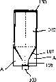
图16是本发明申请人提出的用于墨粉补给装置的粉体收纳容器一例的斜视图。Fig. 16 is a perspective view of an example of a powder storage container used in a toner supply device proposed by the applicant of the present invention.
在图16中,符号101是由收纳粉体状墨粉的墨粉收纳容器构成的粉体收纳容器。本实施例的墨粉收纳容器101是所谓内袋型收纳容器,其由袋体102和外容器体130构成,上述袋体为收纳墨粉的可变形袋体(以下,简记为墨粉袋),上述外容器体收纳该袋体,刚性比袋体大(以下,简记为外箱体)。In FIG. 16 ,
墨粉袋102通过吹喷成型法等由树脂等形成,并在设有墨粉排出部的接口部件103上固定墨粉袋构成,该墨粉袋102使用例如80-200μm左右的聚乙烯或尼龙等树脂制或纸制的挠性片材,以单层或若干层热封制作而成。在墨粉排出部,设有以泡沫海绵等制成的密封阀(没有图示)。该墨粉袋102包括大致呈长方体的主体部106、锥形部107以及圆筒状细口部108,该主体部106的底面形成锥状,成为前端细的锥形部107,圆筒状细口部108与上述锥形部107的前端相连。由于形成上述锥形部107和圆筒状细口部108,能使墨粉收纳容器101的残留墨粉少。上述接口部件103安装在细口部108的前端。另外,符号109是过滤部件,作为能通过空气不能通过墨粉的排气部。The
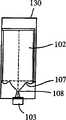
这样所构成的墨粉收纳容器101用外箱体130覆盖住有柔软性的墨粉袋102,有许多优点,搬运性好,且使用完的容器仅更换墨粉袋102,外箱体130能反复使用。The
但是,这样构成的墨粉收纳容器101通常如图17所示,墨粉袋102收纳在外箱体130中,若在搬运时因某种原因受到冲击等场合,因所收纳墨粉重量等原因,有时墨粉袋102如图18所示在接口部件103附近的前端细部被压曲。若在墨粉袋被压曲状态下使用该墨粉收纳容器101,接口部件103附近因压曲导致变狭,墨粉排出部易闭合,墨粉排出不顺畅,存在产生多量残留墨粉问题。However, the
图19是表示本发明粉体收纳容器第七实施例的斜视图,是作为本发明涉及的粉体收纳容器的墨粉收纳容器的分解斜视图。容器本身结构与图16大致相同,同一部件用同一符号表示。19 is a perspective view showing a seventh embodiment of the powder storage container of the present invention, and is an exploded perspective view of the toner storage container as the powder storage container according to the present invention. The structure of the container itself is substantially the same as that in Fig. 16, and the same parts are represented by the same symbols.
在图19中,在外箱体130的内壁面上设有止滑部件120作为减轻压曲机构,该止滑部件120形成为棱状,其朝从接口部件103的墨粉排出口排出墨粉方向的垂直方向延伸。只要止滑部件120能咬合在收纳于外箱体130中的墨粉袋102的面上,其设置位置是任意的,但最好是图19所示位置,下面对此进行说明。In FIG. 19 , an
在本实施例的墨粉收纳容器101中,墨粉袋102朝墨粉排出口103的所有面(四个面)形成角锥状,成为锥部107,外箱体130的对向两面与墨粉袋102的锥部107相对应,从中间开始形成锥部131,另一对对向面132整个面是垂直面。因此,将墨粉袋102插入外箱体130的墨粉收纳容器101形成如图17符号A所示的空间部分。若对该墨粉收纳容器101给予某种形式的冲击等,在该空间A的压曲量比锥部131部分大。因此,止滑部件120设在外箱体130的垂直面132的咬合墨粉袋102的主体部106的位置,能有效减轻在空间A的压曲。In the
另外,止滑部件120位于锥部107的上方,最好设置为在接近锥部107的位置咬合主体部106。这是由于墨粉收纳容器装在图像形成装置中使用,墨粉有某种程度消耗时即使受到冲击等,在有墨粉位置的止滑部件120有效地起作用,在没有墨粉位置的止滑部件120几乎没有效果。止滑部件120至少设置一个,例如图20所示,设有四个,其中至少一个应配置在接近锥部107的位置与主体部106咬合。In addition, the
本实施例的止滑部件120为带状板片部件,其具体尺寸如下:厚度4mm,宽度10mm左右,长度90mm(对于横向宽度112mm的墨粉袋102)。关于厚度,2-10mm有效。以板片部件构成止滑部件120场合,若其棱线部分有棱角,恐怕会损伤墨粉袋102,从而引起墨粉泄漏,因此,如图21所示,最好对棱线部分倒圆角。The
由于止滑部件120抑制墨粉袋102的主体部106因冲击等原因移向墨粉排出口103侧,作为咬合面的止滑部件120的表面需要某种程度的静摩擦系数。根据试验,止滑部件120的表面的静摩擦系数若大于等于2.5,对抑制主体部移动很有效。Since the
如图16中虚线剖面线所示,墨粉袋102在其上部形成三角形状的折入部110。该折入部110是形成长方体袋时因制袋需要形成的。另外,在墨粉袋102的棱线部分,用实线剖面线表示的带状部分是制袋时形成的热封部分。As shown by the dotted hatching in FIG. 16 , the
图22是表示本发明粉体收纳容器第八实施例的斜视图,其表示巧妙利用上述折入部110的减轻压曲机构。FIG. 22 is a perspective view showing the eighth embodiment of the powder storage container of the present invention, which shows the buckling reduction mechanism that skillfully utilizes the folded-in
在图22中,在外箱体130的上板133的内面侧的与所收纳的墨粉袋102的两折入部110分别对应的位置设有插入部件121和122,该插入部件121、122形成截面为“L”字形的钩状,作为减轻压曲机构。该插入部件121、122的宽度L比上述折入部110的宽度L1狭若干,插入由上述折入部110所形成的间隙111的大致全域。插入部件121、122一体成形或用粘结剂固定在外箱体130的上板133上。当将墨粉袋102插入外箱体130组装时,如图23所示,插入部件121、122插入由上述折入部110所形成的间隙111。In FIG. 22, inserting
在这样构成的墨粉收纳容器101中,墨粉袋102通过插入部件121、122实际上吊挂在外箱体130上,即使受到落下等冲击,墨粉袋102也不会大移动。因此,能可靠减轻图18所示墨粉袋102的锥部107和细口部108部分发生的压曲。而且,利用制作墨粉袋102时形成的折入部110,所以,为了减轻压曲不需要对墨粉袋102作特别加工,抑制成本增加。在本实施例中,插入部件121、122以具有宽度L的钩状部件构成,但该插入部件121、122也可以是在与宽度L的大致两端部相当位置上分别设置的轴或短宽度的“L”字形钩。In the
当将墨粉袋102插入外箱体130组装时,插入部件121、122插入由折入部110所形成的间隙111,可以进行上述作业。When the
图24是图22的容器的变型例的说明图,该变型例是对插入部件121插入间隙111的插入作业的进一步改进,面向外箱体130一方向的板材是可开闭的开闭板134、135,当将墨粉袋102插入外箱体130时,打开该开闭板134、135,插入墨粉袋102。插入后,关闭该开闭板134、135,组装墨粉收纳容器101。于是,通过将上述插入部件121粘接在开闭板134上进行安装。Fig. 24 is an explanatory diagram of a modification of the container of Fig. 22. This modification is a further improvement of the insertion operation of the
若采用上述结构,关闭开闭板134时,能将插入部件121插入由上述折入部110所形成的间隙111,提高插入作业性。这种场合,不设置里侧的插入部件122,仅设置一个插入部件121,但即使只有一个插入部件121也能维持吊挂墨粉袋102状态,能充分减轻压曲。According to the above structure, when the opening and closing plate 134 is closed, the
图25是表示本发明粉体收纳容器第九实施例的斜视图,表示另一种减轻压曲机构。在本实施例中,利用图16中实线剖面线所表示的热封部104。在图25中,在上述开闭板134的开闭侧(图示左端侧)通过粘接等设有夹持部件136,其与外箱体130的垂直板132一起夹持热封部104。Fig. 25 is a perspective view showing the ninth embodiment of the powder storage container of the present invention, showing another buckling reduction mechanism. In this embodiment, the heat-
这样构成的减轻压曲机构与上述实施例一样,关闭开闭板134时,用夹持部件136与垂直板132夹持墨粉袋102的热封部104,作业简单,能可靠减轻压曲。另外,如图25虚线所示,若使热封部104的被夹持部件136夹持部分104a比其它部分突出到外侧,则能更容易进行夹持。也可以不设置夹持部件136,而用开闭板134和面板132夹持热封部104,这种场合,若设置突出部分104a,能简单且可靠地进行。The buckling reducing mechanism constituted in this way is the same as the above-mentioned embodiment. When the opening and closing plate 134 is closed, the heat-sealed
图26是表示本发明粉体收纳容器第十实施例的斜视图,表示又一种减轻压曲机构。本实施例的减轻压曲机构是缓冲体115,其形成使墨粉袋102插入外箱体130时形成的空间A大致消失的形状。该缓冲体115是例如泡沫苯乙烯等,也可以在墨粉袋102插入外箱体130后再嵌合,但若预先粘结在外箱体上,作业性好。Fig. 26 is a perspective view showing the tenth embodiment of the powder storage container of the present invention, showing yet another buckling reduction mechanism. The buckling reduction mechanism of this embodiment is the buffer body 115, which is formed in such a shape that the space A formed when the
这样构成的墨粉收纳容器101即使受到冲击,由于与外箱体130之间没有沉入墨粉袋102的空间,能更可靠地减轻压曲。Even if the
上述减轻压曲机构全部都是将部件设在外箱体130上或利用外箱体130,图27所示第十一实施例则将减轻压曲机构设在墨粉袋102上。All the above-mentioned buckling-reducing mechanisms are provided on the
在图27中,本实施例的墨粉袋102设有若干脚状辅助片116。如图28所示,将墨粉袋102插入外箱体130时,该辅助片116的长度达到与外箱体130的底板107相接的位置或与其接近的位置。In FIG. 27, the
这样构成的墨粉袋102由于设有辅助片116,即使受到冲击,通过该辅助片116也能减轻压曲。而且,辅助片116设于墨粉袋102上,因此,也能适用于无外箱体130仅由可变形墨粉袋102所构成的墨粉收纳容器。Since the
在墨粉袋102上设置辅助片116场合,也可以分别形成辅助片116与墨粉袋102,通过粘结等方法将两者固接,但若将两者形成为一体,不仅在费用上合算,而且对于辅助片116的强度来说也非常有利。本实施例的墨粉袋102用四张薄膜制作,其接缝处形成热封部104。在墨粉袋102上设有锥部107及细口部108,制袋时,如图29所示,与墨粉袋102的锥部107相连,形成片片。图16所示墨粉袋102是沿切断线S切断这些片片,而在本实施例中不切断而构成辅助片116。In the case where the
若采用上述方法,能简单设有辅助片116,成本也能大幅度减轻。在图29所示辅助片116中,用逆剖面线表示部分通常不施以热封加工,但若该部分也施以热封加工的话,增加了辅助片116的强度,更为有效。According to the method described above, the
图30表示使用本发明涉及的墨粉收纳容器101的图像形成装置的墨粉补给机构,符号140表示显影装置,在其附近或一体地设有一轴偏心的螺旋泵,图中所示是吸入型的粉体泵141。该粉体泵141包括用金属等具有刚性的材料制作成偏心螺旋状的转子142、用橡胶等弹性体制作形成两条螺旋形状的定子143以及包住上述转子定子且形成粉体运送通道的由树脂材料等制作的支架144。通过销接头与驱动轴145相接,而驱动轴145与齿轮146一体连接,通过上述齿轮146和驱动轴145驱动上述转子回转。符号147是电磁离合器,通过该离合器控制粉体泵141运转。Fig. 30 shows the toner replenishing mechanism of the image forming apparatus using the
另外,在支架144的前端即图30的支架144的右端设有墨粉吸入部148,通过墨粉移送管149连接该墨粉吸入部148和设于喷嘴160上的墨粉用连接口165。该墨粉移送管149可以是例如直径4-10mm的挠性管,若使用耐墨粉性良好的橡胶材料,例如聚氨基甲酸脂、腈、EPDM、硅等制作则非常有效,挠性管很容易朝上下左右任意方向进行配置。在这样构成的墨粉补给装置中,作为粉体泵141的一轴偏心的螺旋泵能以高的固气比连续定量进行移送,能得到与转子142的回转数成正比的正确的墨粉移送量。于是,通过检测图像浓度等若发出墨粉补给指令,则粉体泵142动作,所要求量的墨粉补充给显影装置140。In addition, a toner suction portion 148 is provided at the front end of the
另一方面,设置墨粉收纳容器101的图像形成装置本体的设置部150作为与显影装置140分开的另一个组件构成。插入墨粉袋102内的喷嘴160立设在该设置部150内,从上方将上述墨粉收纳容器101设置在图像形成装置本体的设置部150中。设于设置部150中的喷嘴160通过一体成形或固结等在上部形成截面为锥状的尖端部件161,紧接该尖端部件161设有气体供给通道162和墨粉供给通道163。在喷嘴160内部成为双层管结构,墨粉供给通道163在喷嘴160下端往图左方弯曲,在其前端设有墨粉用连接口165。另外,空气供给通道162在墨粉供给通道163弯曲部上方往图右方弯曲,达到空气连接口164。在墨粉收纳容器101的接口部件103上装有以海绵等构成的自闭阀,能设置到设置部150。On the other hand, the
本实施例场合,空气连接口164通过空气移送管152与作为空气供给装置的气泵151连接。若该气泵151动作,空气从该气泵通过空气移送管152及空气供给通道162喷出到墨粉收纳容器101内。喷出到墨粉收纳容器101内的空气通过墨粉层,一边使墨粉扩散一边使其流动。In this embodiment, the
这样构成的墨粉补给装置将空气供给到墨粉收纳容器101内,提高墨粉袋102内的内压,促进墨粉搅拌流动,在这种状态下,从墨粉收纳容器101排出墨粉。这时,上述粉体泵141辅助排出墨粉,同时,能可靠地将排出的墨粉补给显影装置140。The toner supply device configured in this way supplies air into the
本发明的粉体收纳容器若并用上述作为减轻压曲机构的止滑部件、插入部件、夹持部件、缓冲体及辅助片,能更可靠地减轻压曲。另外,本发明的粉体收纳容器中的粉体,并不局限于墨粉,对于墨粉与载体构成的显影剂或载体等也能适用,因此,例如显影剂或载体等收纳容器也能适用。The powder storage container of the present invention can more reliably reduce buckling if the above-mentioned anti-slip member, insertion member, clamping member, cushioning body, and auxiliary sheet are used together as the buckling reducing mechanism. In addition, the powder in the powder storage container of the present invention is not limited to toner, and it can also be applied to a developer or a carrier composed of a toner and a carrier. Therefore, for example, a storage container such as a developer or a carrier can also be applied. .
当然,本发明并不局限于上述实施例,在本发明技术思想范围内可以作种种变更,它们都属于本发明的保护范围。Certainly, the present invention is not limited to the above-mentioned embodiments, and various changes can be made within the scope of the technical thought of the present invention, and they all belong to the protection scope of the present invention.
Claims (26)
Applications Claiming Priority (4)
| Application Number | Priority Date | Filing Date | Title |
|---|---|---|---|
| JP1806/2000 | 2000-01-07 | ||
| JP2000001806AJP4095747B2 (en) | 2000-01-07 | 2000-01-07 | Powder container, powder discharge device, and image forming apparatus |
| JP2000183568AJP4038324B2 (en) | 2000-06-19 | 2000-06-19 | Powder container and image forming apparatus |
| JP183568/2000 | 2000-06-19 |
Publications (2)
| Publication Number | Publication Date |
|---|---|
| CN1304062A CN1304062A (en) | 2001-07-18 |
| CN1222839Ctrue CN1222839C (en) | 2005-10-12 |
Family
ID=26583255
Family Applications (1)
| Application Number | Title | Priority Date | Filing Date |
|---|---|---|---|
| CNB011013729AExpired - LifetimeCN1222839C (en) | 2000-01-07 | 2001-01-03 | Powder receiving container, powder discharge device and apparatus for image formation |
Country Status (8)
| Country | Link |
|---|---|
| US (1) | US6549744B2 (en) |
| EP (2) | EP1475674B1 (en) |
| KR (1) | KR100386096B1 (en) |
| CN (1) | CN1222839C (en) |
| DE (2) | DE60127733T2 (en) |
| MX (1) | MXPA01000062A (en) |
| SG (1) | SG103274A1 (en) |
| TW (2) | TWI287696B (en) |
Families Citing this family (55)
| Publication number | Priority date | Publication date | Assignee | Title |
|---|---|---|---|---|
| US6725536B1 (en)* | 1999-03-10 | 2004-04-27 | Micron Technology, Inc. | Methods for the fabrication of electrical connectors |
| JP3570714B2 (en)* | 2001-05-24 | 2004-09-29 | 株式会社リコー | Developer container and image forming apparatus |
| JP2003048631A (en) | 2001-05-31 | 2003-02-21 | Ricoh Co Ltd | Multipurpose storage table |
| JP2003234887A (en) | 2002-02-08 | 2003-08-22 | Ricoh Co Ltd | Image forming method, image forming apparatus, computer program, and storage medium |
| US20050081950A1 (en)* | 2002-04-01 | 2005-04-21 | Ilc Dover, Inc | Flexible containment charging device |
| US6832852B2 (en)* | 2002-04-27 | 2004-12-21 | Kenneth R. Wilkes | Gusseted flexible bottle with fitment and method of fabrication |
| AU2003224903A1 (en)* | 2002-04-27 | 2003-11-17 | River Solutions, Inc. | Gusseted flexible bottle with fitment and method of fabrication |
| GB2392148B (en)* | 2002-08-21 | 2005-11-23 | Ice Packaging Ltd | A powder container |
| WO2004027522A1 (en) | 2002-09-20 | 2004-04-01 | Ricoh Company, Limited | Image forming device, powder feeding device, toner storage container, powder storage container, and method of recycling the containers |
| JP4220798B2 (en)* | 2002-09-20 | 2009-02-04 | 株式会社リコー | Powder container |
| WO2004062393A2 (en)* | 2003-01-03 | 2004-07-29 | H.J. Heinz Company | Condiment dispenser |
| US7340230B2 (en)* | 2003-04-14 | 2008-03-04 | Silicon Laboratories Inc. | Receiver architectures utilizing coarse analog tuning and associated methods |
| JP4584659B2 (en)* | 2003-09-30 | 2010-11-24 | 株式会社リコー | Container storage box for easily deformable containers containing powder for image formation |
| EP1589384B1 (en)* | 2004-04-23 | 2020-01-08 | Ricoh Company, Ltd. | Developer container |
| US7054582B2 (en)* | 2004-06-28 | 2006-05-30 | General Plastic Industrial Co., Ltd | Toner cartridge |
| JP4713295B2 (en)* | 2004-11-09 | 2011-06-29 | 株式会社リコー | Volume reduction device and toner supply device |
| CN100454166C (en)* | 2004-11-09 | 2009-01-21 | 株式会社理光 | Toner container, toner supply device and image forming apparatus |
| US7620349B2 (en)* | 2005-03-15 | 2009-11-17 | Ricoh Co., Ltd. | Agent containing unit having improved usability, agent refill unit, and image forming apparatus |
| JP4926563B2 (en)* | 2006-06-28 | 2012-05-09 | 東京応化工業株式会社 | Container for fluid and container containing fluid using the same |
| USD592819S1 (en) | 2007-05-03 | 2009-05-19 | Johnsondiversey, Inc. | Valve assembly for a floor maintenance tool |
| USD590117S1 (en) | 2007-05-03 | 2009-04-07 | Johnsondiversey, Inc. | Floor maintenance tool |
| USD602664S1 (en) | 2007-05-03 | 2009-10-20 | Johnsondiversey, Inc. | Floor maintenance tool |
| CA2697158A1 (en)* | 2007-08-20 | 2009-02-26 | Frank Ianna | Condiment packet |
| EP2103547B1 (en)* | 2008-03-22 | 2013-03-20 | Pall Corporation | Biocontainer |
| EP2103548B1 (en)* | 2008-03-22 | 2014-10-01 | Pall Corporation | System comprising a tote and a flexible container |
| US8348509B2 (en)* | 2009-09-10 | 2013-01-08 | Smart Bottle, Inc. | Flexible container with fitment and handle |
| US8231029B2 (en)* | 2009-09-10 | 2012-07-31 | Smart Bottle Inc. | Flexible container having flexible handles |
| CN102947762B (en)* | 2010-04-27 | 2016-06-08 | 株式会社理光 | Powder collecting container, powder transfer device and image processing system |
| EP2691817B1 (en) | 2011-03-30 | 2021-06-30 | Ricoh Company, Ltd. | Powder storage container and image forming apparatus |
| DE202011109209U1 (en)* | 2011-12-16 | 2012-07-24 | Bischof + Klein Gmbh & Co. Kg | Side gusset bag made of foil |
| EP2807087A1 (en)* | 2012-01-26 | 2014-12-03 | Pall Technology UK limited | Flexible fluid vessel and related methods |
| WO2013121247A1 (en) | 2012-02-15 | 2013-08-22 | CBC (Europe) Ltd. | System and method for dispensing particulate material |
| JP6019799B2 (en)* | 2012-06-22 | 2016-11-02 | 株式会社リコー | Toner supply container |
| JP6066841B2 (en)* | 2012-09-10 | 2017-01-25 | キヤノン株式会社 | Developing cartridge, process cartridge, and image forming apparatus |
| US9465317B2 (en)* | 2013-02-25 | 2016-10-11 | Ricoh Company, Ltd. | Nozzle insertion member, powder container, and image forming apparatus |
| KR101699196B1 (en) | 2013-03-14 | 2017-01-23 | 가부시키가이샤 리코 | Toner container and image forming apparatus |
| CN105473031B (en)* | 2013-05-10 | 2018-11-02 | 竹斯柔公司 | Juicing system and method |
| JP6137952B2 (en)* | 2013-06-11 | 2017-05-31 | キヤノン株式会社 | Image forming apparatus |
| RU2668632C2 (en) | 2014-03-17 | 2018-10-02 | Рикох Компани, Лимитед | Nozzle receiver, powder container, and image forming apparatus |
| US10647563B2 (en)* | 2014-12-30 | 2020-05-12 | Edward Showalter | Apparatus, systems and methods for dispensing drinks |
| US11292706B2 (en)* | 2014-12-30 | 2022-04-05 | Edward Showalter | Apparatus, systems and methods for preparing and dispensing foods |
| US20170252990A1 (en)* | 2016-03-03 | 2017-09-07 | Juicero, Inc. | Juicer cartridge geometry |
| US20170252999A1 (en)* | 2016-03-03 | 2017-09-07 | Juicero, Inc. | Juicer with juicer cartridge orientation feature |
| US20170252996A1 (en)* | 2016-03-03 | 2017-09-07 | Juicero, Inc. | Juicer cartridge with secondary flow channel |
| US20170253000A1 (en)* | 2016-03-03 | 2017-09-07 | Juicero, Inc. | Juicer with locking mechanism |
| US20170251863A1 (en)* | 2016-03-03 | 2017-09-07 | Juicero, Inc. | Angled juicing system |
| US20170252994A1 (en)* | 2016-03-03 | 2017-09-07 | Juicero, Inc. | Juicing system with juicer cartridge restraints |
| US20170252995A1 (en)* | 2016-03-03 | 2017-09-07 | Juicero, Inc. | Juicer cartridge with outlet separator |
| US20170252998A1 (en)* | 2016-03-03 | 2017-09-07 | Juicero, Inc. | Juicer cartridge with flow disruptor |
| US20170252993A1 (en)* | 2016-03-03 | 2017-09-07 | Juicero, Inc. | Juicer cartridge with coupling |
| US20170252991A1 (en)* | 2016-03-03 | 2017-09-07 | Juicero, Inc. | Juicer with flexible seal |
| US20170252997A1 (en)* | 2016-03-03 | 2017-09-07 | Juicero, Inc. | Juicer cartridge with sanitary seal |
| BR112018014972B1 (en)* | 2016-05-12 | 2022-02-01 | Hewlett-Packard Development Company, L.P | 3d printing building material containers |
| TWI668176B (en)* | 2018-08-01 | 2019-08-11 | 日月光半導體製造股份有限公司 | Wires collection container |
| CN117908343A (en)* | 2019-08-09 | 2024-04-19 | 佳能株式会社 | Toner container |
Family Cites Families (14)
| Publication number | Priority date | Publication date | Assignee | Title |
|---|---|---|---|---|
| US3374929A (en)* | 1966-09-23 | 1968-03-26 | Silfverskiold Lennart | Bulk containers |
| US4113146A (en)* | 1974-04-11 | 1978-09-12 | Better Agricultural Goals Corporation | Disposable container for bulk materials |
| GB2041318B (en) | 1979-02-14 | 1983-05-25 | Oordt & Co Holding Bv | Double-walled air-tight package and a method of manufacturing such a package |
| US4673112A (en)* | 1983-06-03 | 1987-06-16 | Vincent C. Bonerb | Material handling bins with inflatable liners |
| US5016779A (en)* | 1990-02-09 | 1991-05-21 | Nic Williamson | Apparatus for dispensing measured amounts of fluid from an open-ended pouch |
| JPH06274031A (en) | 1993-03-23 | 1994-09-30 | Tokyo Electric Co Ltd | Toner replenishing device for electrophotographic device |
| US5402915A (en)* | 1993-11-30 | 1995-04-04 | Kaneka Texas Corporation | Bottom draining bin-type, bulk fluid container with insert |
| US5426492A (en)* | 1994-04-11 | 1995-06-20 | Xerox Corporation | Space optimizing toner cartridge |
| CA2146102C (en)* | 1995-03-31 | 2000-07-25 | Hermann Ophardt | Bag fluid dispenser |
| JP3784454B2 (en)* | 1995-04-07 | 2006-06-14 | 株式会社リコー | Filled toner supply container and manufacturing method thereof |
| JP3437332B2 (en) | 1995-07-10 | 2003-08-18 | キヤノン株式会社 | Powder supply container, method of manufacturing powder supply container, and powder supply method |
| JPH11119536A (en) | 1997-10-20 | 1999-04-30 | Canon Inc | Dry type electrophotographic toner bottle |
| FR2772730B1 (en) | 1997-12-24 | 2000-03-10 | Agriplas | DEVICE FOR PACKAGING AND TRANSPORTING LIQUID OR POWDER PRODUCTS |
| JP4084457B2 (en) | 1998-03-31 | 2008-04-30 | 株式会社リコー | Agent storage container and image forming apparatus |
- 2001
- 2001-01-03CNCNB011013729Apatent/CN1222839C/ennot_activeExpired - Lifetime
- 2001-01-03USUS09/752,447patent/US6549744B2/ennot_activeExpired - Lifetime
- 2001-01-04KRKR10-2001-0000321Apatent/KR100386096B1/ennot_activeExpired - Fee Related
- 2001-01-05DEDE60127733Tpatent/DE60127733T2/ennot_activeExpired - Lifetime
- 2001-01-05TWTW093118637Apatent/TWI287696B/ennot_activeIP Right Cessation
- 2001-01-05EPEP04017178Apatent/EP1475674B1/ennot_activeExpired - Lifetime
- 2001-01-05TWTW090100396Apatent/TWI233007B/ennot_activeIP Right Cessation
- 2001-01-05DEDE60127875Tpatent/DE60127875T2/ennot_activeExpired - Lifetime
- 2001-01-05EPEP01100032Apatent/EP1115036B1/ennot_activeExpired - Lifetime
- 2001-01-06SGSG200100123Apatent/SG103274A1/enunknown
- 2001-01-08MXMXPA01000062Apatent/MXPA01000062A/enactiveIP Right Grant
Also Published As
| Publication number | Publication date |
|---|---|
| EP1475674A1 (en) | 2004-11-10 |
| TWI233007B (en) | 2005-05-21 |
| US6549744B2 (en) | 2003-04-15 |
| EP1115036B1 (en) | 2007-04-11 |
| KR20010100759A (en) | 2001-11-14 |
| CN1304062A (en) | 2001-07-18 |
| MXPA01000062A (en) | 2002-08-06 |
| EP1115036A1 (en) | 2001-07-11 |
| TWI287696B (en) | 2007-10-01 |
| DE60127733D1 (en) | 2007-05-24 |
| TW200422797A (en) | 2004-11-01 |
| DE60127875D1 (en) | 2007-05-24 |
| DE60127875T2 (en) | 2008-01-17 |
| HK1035579A1 (en) | 2001-11-30 |
| DE60127733T2 (en) | 2007-12-27 |
| KR100386096B1 (en) | 2003-06-02 |
| US20010017998A1 (en) | 2001-08-30 |
| EP1475674B1 (en) | 2007-04-11 |
| SG103274A1 (en) | 2004-04-29 |
Similar Documents
| Publication | Publication Date | Title |
|---|---|---|
| CN1222839C (en) | Powder receiving container, powder discharge device and apparatus for image formation | |
| CN1119715C (en) | Toner container, imaging method and device with same | |
| CN1222841C (en) | Powder storage container, method for assembling the container, and method for reducing volume | |
| CN1237409C (en) | Powder holding container, method for assembling said container and image forming device | |
| CN1229696C (en) | Color image forming apparatus and toner storage container | |
| CN100337162C (en) | Main element of powder container | |
| CN1118722C (en) | Toner replenishment cartridge, sealing member, and electrophotographic image forming apparatus | |
| CN1892491A (en) | Developer filling apparatus and developer filling system having the same | |
| CN1661490A (en) | Toner supply container and image forming apparatus | |
| CN1207511A (en) | Toner replenishment cartridge and image forming apparatus for electrophotography | |
| CN1136502A (en) | Ink box and treating card box | |
| CN1157942A (en) | Toner regulating container, process cartridge and image forming apparatus for electrophotographic printing | |
| CN1187659C (en) | Toner supply device and image forming device | |
| CN1148618C (en) | Powder collecting container and imaging device | |
| CN1719348A (en) | Developer supply device and image forming device having same | |
| CN1609728A (en) | Developer container and imaging device | |
| CN1823307A (en) | Developer storage container and image forming apparatus | |
| HK1035579B (en) | Powder accepting container, powder exhausting device and image generation device | |
| CN1680103A (en) | Ink Supply Structure | |
| CN2795902Y (en) | Developer device | |
| CN1591229A (en) | Developer container and image forming apparatus | |
| JP4113885B2 (en) | Powder container and image forming apparatus | |
| JP4362336B2 (en) | Developer supply apparatus and image forming apparatus | |
| JP2000267414A (en) | Toner storage container | |
| JP4056037B2 (en) | Toner storage container, image forming apparatus using the same, and image forming method |
Legal Events
| Date | Code | Title | Description |
|---|---|---|---|
| C10 | Entry into substantive examination | ||
| SE01 | Entry into force of request for substantive examination | ||
| C06 | Publication | ||
| PB01 | Publication | ||
| C14 | Grant of patent or utility model | ||
| GR01 | Patent grant | ||
| REG | Reference to a national code | Ref country code:HK Ref legal event code:GR Ref document number:1080764 Country of ref document:HK | |
| CX01 | Expiry of patent term | ||
| CX01 | Expiry of patent term | Granted publication date:20051012 |