CN1222103C - Gyroscopic detector of DC motor and gyroscopic controller - Google Patents
Gyroscopic detector of DC motor and gyroscopic controllerDownload PDFInfo
- Publication number
- CN1222103C CN1222103CCNB001364677ACN00136467ACN1222103CCN 1222103 CCN1222103 CCN 1222103CCN B001364677 ACNB001364677 ACN B001364677ACN 00136467 ACN00136467 ACN 00136467ACN 1222103 CCN1222103 CCN 1222103C
- Authority
- CN
- China
- Prior art keywords
- motor
- rotation
- mentioned
- control
- signal
- Prior art date
- Legal status (The legal status is an assumption and is not a legal conclusion. Google has not performed a legal analysis and makes no representation as to the accuracy of the status listed.)
- Expired - Fee Related
Links
- 238000001514detection methodMethods0.000claimsdescription146
- 230000000052comparative effectEffects0.000claimsdescription12
- 230000001186cumulative effectEffects0.000abstractdescription17
- 238000010586diagramMethods0.000description52
- 238000000034methodMethods0.000description26
- 230000008859changeEffects0.000description21
- 101000653548Homo sapiens Trichoplein keratin filament-binding proteinProteins0.000description15
- 102100030645Trichoplein keratin filament-binding proteinHuman genes0.000description15
- YCCHNFGPIFYNTF-UHFFFAOYSA-Ntertiary cymene hydroperoxideNatural productsCC1=CC=C(C(C)(C)OO)C=C1YCCHNFGPIFYNTF-UHFFFAOYSA-N0.000description15
- WLPUWLXVBWGYMZ-UHFFFAOYSA-NtricyclohexylphosphineChemical compoundC1CCCCC1P(C1CCCCC1)C1CCCCC1WLPUWLXVBWGYMZ-UHFFFAOYSA-N0.000description15
- 230000009471actionEffects0.000description13
- 239000003990capacitorSubstances0.000description13
- 102100028918Catenin alpha-3Human genes0.000description7
- 101000916179Homo sapiens Catenin alpha-3Proteins0.000description7
- 230000008569processEffects0.000description7
- 230000007423decreaseEffects0.000description6
- 230000008030eliminationEffects0.000description6
- 238000003379elimination reactionMethods0.000description6
- 230000004044responseEffects0.000description6
- 230000000630rising effectEffects0.000description6
- 230000000737periodic effectEffects0.000description3
- 101710130550Class E basic helix-loop-helix protein 40Proteins0.000description2
- 102100025314Deleted in esophageal cancer 1Human genes0.000description2
- 230000005284excitationEffects0.000description2
- 230000007246mechanismEffects0.000description2
- 230000003287optical effectEffects0.000description2
- 230000002093peripheral effectEffects0.000description2
- 230000002441reversible effectEffects0.000description2
- 230000001133accelerationEffects0.000description1
- 230000005540biological transmissionEffects0.000description1
- 230000015572biosynthetic processEffects0.000description1
- 239000004020conductorSubstances0.000description1
- 230000003111delayed effectEffects0.000description1
- 230000000694effectsEffects0.000description1
- 238000005516engineering processMethods0.000description1
- 238000003384imaging methodMethods0.000description1
- 230000006698inductionEffects0.000description1
- 238000007493shaping processMethods0.000description1
- 230000006641stabilisationEffects0.000description1
- 238000011105stabilizationMethods0.000description1
- 230000001360synchronised effectEffects0.000description1
- 238000003786synthesis reactionMethods0.000description1
- 238000004804windingMethods0.000description1
Images


Classifications
- H—ELECTRICITY
- H02—GENERATION; CONVERSION OR DISTRIBUTION OF ELECTRIC POWER
- H02P—CONTROL OR REGULATION OF ELECTRIC MOTORS, ELECTRIC GENERATORS OR DYNAMO-ELECTRIC CONVERTERS; CONTROLLING TRANSFORMERS, REACTORS OR CHOKE COILS
- H02P7/00—Arrangements for regulating or controlling the speed or torque of electric DC motors
- H02P7/06—Arrangements for regulating or controlling the speed or torque of electric DC motors for regulating or controlling an individual DC dynamo-electric motor by varying field or armature current
- H02P7/18—Arrangements for regulating or controlling the speed or torque of electric DC motors for regulating or controlling an individual DC dynamo-electric motor by varying field or armature current by master control with auxiliary power
- H02P7/24—Arrangements for regulating or controlling the speed or torque of electric DC motors for regulating or controlling an individual DC dynamo-electric motor by varying field or armature current by master control with auxiliary power using discharge tubes or semiconductor devices
- H02P7/28—Arrangements for regulating or controlling the speed or torque of electric DC motors for regulating or controlling an individual DC dynamo-electric motor by varying field or armature current by master control with auxiliary power using discharge tubes or semiconductor devices using semiconductor devices
- H—ELECTRICITY
- H02—GENERATION; CONVERSION OR DISTRIBUTION OF ELECTRIC POWER
- H02K—DYNAMO-ELECTRIC MACHINES
- H02K23/00—DC commutator motors or generators having mechanical commutator; Universal AC/DC commutator motors
- H02K23/66—Structural association with auxiliary electric devices influencing the characteristic of, or controlling, the machine, e.g. with impedances or switches
- H—ELECTRICITY
- H02—GENERATION; CONVERSION OR DISTRIBUTION OF ELECTRIC POWER
- H02P—CONTROL OR REGULATION OF ELECTRIC MOTORS, ELECTRIC GENERATORS OR DYNAMO-ELECTRIC CONVERTERS; CONTROLLING TRANSFORMERS, REACTORS OR CHOKE COILS
- H02P7/00—Arrangements for regulating or controlling the speed or torque of electric DC motors
- H02P7/0094—Arrangements for regulating or controlling the speed or torque of electric DC motors wherein the position is detected using the ripple of the current caused by the commutator
Landscapes
- Engineering & Computer Science (AREA)
- Power Engineering (AREA)
- Dc Machiner (AREA)
- Control Of Direct Current Motors (AREA)
Abstract
Description
Translated fromChinese技术领域technical field
本发明涉及使用直流马达(DC马达)作为机械动作的驱动源、且要求该直流马达回转速度稳定化及累积回转数的控制的装置,尤其涉及下述直流马达的回转检测装置和回转控制装置:整流子与转子线圈连接,且与该转子线圈一起设置在转子上,与定子设为一体的一对电极用电刷与上述整流子滑接,通过该电极用电刷及整流子切换直流驱动电压,供给上述转子线圈,检测直流马达的上述转子的回转方向、回转速度及回转位置至少某个,合适地控制上述转子的回转动作。The present invention relates to a device that uses a direct current motor (DC motor) as a driving source for mechanical action, and requires the stabilization of the rotation speed of the DC motor and the control of the cumulative number of rotations, and particularly relates to the rotation detection device and the rotation control device of the following DC motors: The commutator is connected to the rotor coil, and is arranged on the rotor together with the rotor coil, and a pair of electrodes integrated with the stator are in sliding contact with the above-mentioned commutator, and the DC driving voltage is switched by the brush and the commutator through the electrodes. The above-mentioned rotor coil is supplied to detect at least one of the rotation direction, rotation speed and rotation position of the above-mentioned rotor of the DC motor, and the rotation operation of the above-mentioned rotor is appropriately controlled.
背景技术Background technique
以往,大多使用电刷式直流马达作为机械动作的驱动源,上述所谓机械动作是指例如照相机中用于使由变焦透镜所构成的摄影透镜变焦的变焦动作,根据测距信息等被摄体距离信息用于使摄影透镜和成像面的至少一方沿光轴驱动进行调焦的调焦驱动,用于进行摄影胶卷的卷取或卷回的胶卷进给驱动等。电刷式直流马达是在定子上使用永久磁铁等形成若干固定磁极,若干转子线圈形成转子的若干磁极,通过与转子一体回转的整流子以及从定子侧与该整流子滑接的电刷,根据回转角度切换供给直流驱动电流,使转子回转。In the past, a brush-type DC motor was mostly used as the driving source of the mechanical action. The above-mentioned so-called mechanical action refers to the zooming action for zooming the photographic lens composed of the zoom lens in a camera. The information is used for a focus drive for driving at least one of the photographic lens and the imaging plane along the optical axis to adjust focus, for a film feed drive for winding or rewinding a photographic film, and the like. The brush type DC motor uses permanent magnets on the stator to form a number of fixed magnetic poles, and a number of rotor coils form a number of magnetic poles of the rotor. Through the commutator that rotates integrally with the rotor and the brush that slides with the commutator from the stator side, according to Rotation angle switching supplies DC drive current to rotate the rotor.
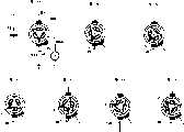
作为这种直流马达可以例举三极马达,如图30所示,表示该马达场合。从直流驱动电源E0通过一对电极用电刷B01、B02,向整流子CM0进行供电,该整流子CM0与上述电极用电刷B01、B02滑接。该电极用电刷B01和B02相对整流子CM0在相差180度位置相接。整流子CM0形成与转子一体动作的圆筒面,本例场合,以等角度间隔即大致以120度三等分接片构成该圆筒面。三个转子线圈分别连接在整流子CM0的各邻接接片间,通过上述转子线圈形成三个转子磁极。As such a DC motor, a three-pole motor can be cited, and the case of this motor is shown in FIG. 30 . The commutator CM0 is supplied with power from the DC drive power source E0 through a pair of electrode brushes B01, B02, and the commutator CM0 is in sliding contact with the above-mentioned electrode brushes B01, B02. The electrodes are connected by brushes B01 and B02 relative to the commutator CM0 at positions 180 degrees apart. The commutator CM0 forms a cylindrical surface that moves integrally with the rotor. In this example, the cylindrical surface is formed by equal angular intervals, that is, roughly divided into three equal parts of 120 degrees. The three rotor coils are respectively connected between adjacent pieces of the commutator CM0, and three rotor magnetic poles are formed by the rotor coils.
根据回转角度不同,电极用电刷B01、B02与整流子CM0的各接片之间的接触状态变化,极性变动,在上述转子磁极与定子侧的由永久磁铁所构成的例如一对定子磁极(没有图示)之间,产生回转驱动力。随着转子回转,各转子磁极顺序与各定子磁极对向,且电极用电刷B01、B02与整流子CM0的各接片之间的接触状态变化,通过各转子磁极的极性顺序变动,转子继续回转。According to the different rotation angles, the contact state between the electrode brushes B01, B02 and the commutator CM0 changes, and the polarity changes. (not shown), a turning driving force is generated. As the rotor rotates, the rotor poles are opposed to the stator poles in sequence, and the contact state between the electrode brushes B01, B02 and the commutator CM0 changes. Through the change of the polarity sequence of the rotor poles, the rotor Keep turning.
即若从电源E0施加电压到一对电极用电刷B01、B02上,则电流从电极用电刷B01、B02中一方通过转子线圈向另一方流动,由于转子线圈产生磁场,形成转子磁极。这样,通过转子线圈产生的磁场与定子磁极所引起的磁场的作用,转子回转。That is, when a voltage is applied from the power supply E0 to the pair of electrode brushes B01, B02, current flows from one of the electrode brushes B01, B02 through the rotor coil to the other, and a magnetic field is generated by the rotor coil to form rotor magnetic poles. In this way, the rotor rotates by the action of the magnetic field generated by the rotor coil and the magnetic field caused by the stator poles.
作为检测这种马达回转的方法一般采用旋转编码方式。即在马达的回转输出轴或响应其回转的传动机构内设置回转狭缝圆盘,在该回转狭缝圆盘周面上形成狭缝,用光断流器检测该回转狭缝圆盘周面的狭缝,检测回转。这种方法确实能检测回转,但需要构成旋转编码器的回转狭缝圆盘及光断流器等,占据空间体积增大,且成本上升。As a method for detecting the rotation of such a motor, a rotary encoding method is generally used. That is, a rotary slit disk is set in the rotary output shaft of the motor or the transmission mechanism that responds to its rotation, and a slit is formed on the peripheral surface of the rotary slit disk, and the peripheral surface of the rotary slit disk is detected by an optical interrupter. The slit detects the rotation. This method can indeed detect rotation, but it requires a rotating slit disk and a photo interrupter constituting the rotary encoder, which increases the occupied space and increases the cost.
除了上述方法之外,还有如图31和32所示的从驱动电流波动检测回转的方法。In addition to the above method, there is a method of detecting slewing from driving current fluctuations as shown in FIGS. 31 and 32 .
在图31中,在从驱动电源E0向一方(例如在图中是电极用电刷B02)供给马达驱动电流的供电电路上串接电阻R0,检测电阻R0的端电压,得到如图32所示的驱动电流的60度周期的波动波形。该波动波形由于与转子的回转角度位置相对应,所以,通过对其作适当波形整形等能得到与回转角度位置相对应的脉冲信号。该方法虽在减少空间体积及成本上有利,但存在因噪音等引起误检测等检测精度方面问题。In Fig. 31, a resistor R0 is connected in series to the power supply circuit that supplies the motor drive current from the driving power supply E0 to one side (for example, the electrode brush B02 in the figure), and the terminal voltage of the resistor R0 is detected, as shown in Fig. 32 The 60-degree cycle fluctuation waveform of the drive current. Since the wave waveform corresponds to the rotational angle position of the rotor, a pulse signal corresponding to the rotational angle position can be obtained by appropriately shaping the waveform or the like. Although this method is advantageous in reducing space volume and cost, it has problems in detection accuracy such as false detection due to noise and the like.
针对上述问题,在特开平4-127864号公报等中公开了一种方法,其设置与一对电极用电刷不同的检测回转用电刷,检测回转。上述检测回转用电刷与一对电极用电刷同样,与整流子滑接,提取整流子中电压。根据该检测回转用电刷所检测到的信号检测回转。In view of the above problems, JP-A-4-127864 and the like disclose a method in which a brush for detecting rotation different from a brush for a pair of electrodes is provided to detect the rotation. The above-mentioned detection rotation brush is the same as the pair of electrode brushes, and is in sliding contact with the commutator to extract the voltage in the commutator. The rotation is detected based on the signal detected by the brush for detecting the rotation.
在上述特开平4-127864号公报等中具体公开了如图33所示结构。马达M0除了一对电极用电刷B01、B02之外还设有检测回转用电刷BD0,在检测回转用电刷BD0上顺序连接微分电路101、时间常数复原电路102及时间常数电路103。上述时间常数电路103的输出端与比较器105的非反转输入端相连接,比较标准电压发生部104的输出端与比较器105的反转输入端相连接。比较器105的输出通过图示极性的二极管106与继电器107的励磁线圈一端相连接。继电器107的励磁线圈另一端与驱动电源E0一端相连接。电极用电刷B01通过继电器107的接点107a与驱动电源E0一端相接,电极用电刷B02直接与驱动电源E0另一端相接。The structure shown in FIG. 33 is specifically disclosed in the above-mentioned JP-A-4-127864 and the like. In addition to a pair of electrode brushes B01 and B02, the motor M0 is provided with a rotation detection brush BD0, and a
上述继电器107的励磁线圈一端通过图示极性的二极管108与马达起动电路109的三极管109a的集电极相连接。马达起动信号通过电阻109b供给三极管109a的基极,在三极管109a的基极与发射极之间连接有电阻109c。三极管109a的发射极与驱动电源E0另一端相接。One end of the exciting coil of the
图34表示上述结构中各部的信号波形,即表示输入到马达起动电路109的马达起动信号、检测回转用电刷BD0的检测信号、微分电路101的输出信号、时间常数电路103的输出信号、比较器105的输出信号、继电器107的动作信号及从驱动电源E0向马达M0的驱动电源供给各波形。34 shows the signal waveforms of each part in the above structure, that is, the motor starting signal input to the
根据马达起动信号,马达起动电路109的三极管109a接通,继电器107接通,接点107a闭合,电力通过电极用电刷B01和B02供给马达M0,马达M0开始回转。随着马达M0回转,从检测回转用电刷BD0输出脉冲列SA0,在微分电路101被微分,将与各脉冲前缘同步的信号SB0供给时间常数复原电路102。时间常数复原电路102与信号SB0同步,使时间常数电路103复原,从时间常数电路103输出信号SC0。According to the motor starting signal, the
在马达M0以通常回转速度回转的通常状态下,从时间常数电路103输出的信号SC0不超过由比较标准电压发生部104供给的比较标准电压。在这种状态下,比较器105的输出信号SD0是“L(低电平)”,继电器107被励磁,继续接通状态,维持对于马达M0的供电。但是,因过负荷等原因,若马达M0的回转速度降低,从时间常数电路103输出的信号SC0超过由比较标准电压发生部104供给的比较标准电压,比较器105的输出信号SD0成为“H(高电平)”,在继电器107中没有励磁电流,成为断开状态,接点107a断开,停止对马达M0的供电。这样,检测马达M0回转速度的降低,停止马达M0,防止过大电流持续流过马达M0。In a normal state where the motor M0 rotates at a normal rotation speed, the signal SC0 output from the time
上述特开平4-127864号公报等公开的方法只不过是马达回转速度有某种程度降低场合使继电器动作,并没有明确表示通过高精度检测回转方向、回转数、回转速度及回转位置等用于回转方向控制、回转数控制及回转速度控制等的技术。The methods disclosed in the above-mentioned Japanese Patent Laid-Open No. 4-127864 and the like are only to activate the relay when the rotational speed of the motor is reduced to a certain extent, and it is not clearly indicated that the rotational direction, the number of revolutions, the rotational speed, and the rotational position are detected by high-precision. Technologies such as rotation direction control, rotation speed control, and rotation speed control.
发明内容Contents of the invention
本发明就是鉴于上述先有技术所存在的问题而提出来的,本发明的目的在于,提供直流马达的回转检测装置、回转控制装置以及装有上述回转检测装置、回转控制装置的电气装置,通过简单结构,可靠检测和控制电刷式直流马达的回转速度、累计回转数、回转方向及回转位置,能有效进行回转控制。The present invention is proposed in view of the above-mentioned problems in the prior art. The purpose of the present invention is to provide a rotation detection device, a rotation control device of a DC motor, and an electrical device equipped with the above rotation detection device and a rotation control device. Simple structure, reliable detection and control of the rotation speed, cumulative number of rotations, rotation direction and rotation position of the brush type DC motor, and effective rotation control.
为了实现上述目的,本发明提出一种直流马达的回转检测装置,一对电极用电刷与整流子滑接,该整流子与转子线圈连接且与该转子线圈一起设于转子上,通过该整流子切换直流驱动电压,供给上述转子线圈,上述一对电极用电刷与定子设为一体,检测回转速度、累计回转数、回转方向及回转位置中至少某个;其特征在于,包括:In order to achieve the above object, the present invention proposes a rotation detection device of a DC motor. A pair of electrodes is slidingly connected to a commutator with brushes. The commutator is connected to the rotor coil and is arranged on the rotor together with the rotor coil. The sub-switches the DC drive voltage to supply the above-mentioned rotor coil, and the above-mentioned pair of electrodes are integrated with the stator to detect at least one of the rotation speed, the cumulative number of rotations, the rotation direction and the rotation position; it is characterized in that it includes:
至少一个检测回转用电刷,用于检测上述转子回转;At least one brush for detecting rotation, used to detect the rotation of the above-mentioned rotor;
标准电压产生装置,用于产生比较标准电压;A standard voltage generating device for generating a comparative standard voltage;
比较器,比较由上述检测回转用电刷所检测的电压和由上述标准电压产生装置产生的比较标准电压;A comparator, which compares the voltage detected by the above-mentioned detection rotation brush with the comparison standard voltage generated by the above-mentioned standard voltage generating device;
脉冲间隔检测装置,用于检测上述比较器的输出脉冲间隔;A pulse interval detection device for detecting the output pulse interval of the above-mentioned comparator;
回转速度计算装置,根据由上述脉冲间隔检测装置所检测到的脉冲间隔求取上述转子的回转速度。The rotation speed calculation means calculates the rotation speed of the rotor based on the pulse interval detected by the pulse interval detection means.
根据本发明的直流马达的回转检测装置,其特征还在于,标准电压产生装置包括对上述直流驱动电压进行分压得到比较标准电压的装置。The rotation detecting device of a DC motor according to the present invention is further characterized in that the standard voltage generating device includes a device for dividing the above-mentioned DC driving voltage to obtain a comparative standard voltage.
为了实现上述目的,本发明提出一种电气装置,其设有本发明的回转检测装置。In order to achieve the above object, the present invention proposes an electrical device, which is provided with the rotation detection device of the present invention.
为了实现上述目的,本发明提出一种直流马达的回转控制装置,一对电极用电刷与整流子滑接,该整流子与转子线圈连接且与该转子线圈一起设于转子上,通过该整流子切换直流驱动电压,供给上述转子线圈,上述一对电极用电刷与定子设为一体,控制上述结构直流马达的转子的回转动作;其特征在于,包括:In order to achieve the above object, the present invention proposes a rotation control device for a DC motor, in which a pair of electrodes is slidingly connected to a commutator with brushes, the commutator is connected to the rotor coil and is arranged on the rotor together with the rotor coil, through the rectifier The sub-switching DC drive voltage is supplied to the above-mentioned rotor coil, and the above-mentioned pair of electrode brushes are integrated with the stator to control the rotation of the rotor of the DC motor with the above-mentioned structure; it is characterized in that it includes:
至少一个检测回转用电刷,用于检测上述转子回转;At least one brush for detecting rotation, used to detect the rotation of the above-mentioned rotor;
马达驱动电路,向上述一对电极用电刷供给上述直流驱动电压,驱动该直流马达;a motor drive circuit that supplies the DC drive voltage to the pair of electrode brushes to drive the DC motor;
标准电压产生装置,用于产生与上述转子的不同回转方向和/或施加到上述直流马达上的电压对应的若干比较标准电压;A standard voltage generating device for generating several comparative standard voltages corresponding to different rotation directions of the above-mentioned rotor and/or voltages applied to the above-mentioned DC motor;
比较器,对由上述检测回转用电刷所检测的电压和由上述标准电压产生装置产生的上述若干比较标准电压之一进行比较。The comparator compares the voltage detected by the brush for detecting rotation with one of the plurality of comparative standard voltages generated by the standard voltage generating device.
马达控制电路,将由上述标准电压产生装置产生的若干比较标准电压中与所希望的回转方向和/或施加到上述直流马达上的电压对应的比较标准电压供给上述比较器,且根据上述回转方向和/或施加到上述直流马达上的电压及上述比较器的输出信号控制上述马达驱动电路;The motor control circuit supplies the comparative standard voltage corresponding to the desired rotation direction and/or the voltage applied to the above-mentioned DC motor among the plurality of comparison standard voltages generated by the above-mentioned standard voltage generating device to the above-mentioned comparator, and according to the above-mentioned rotation direction and /or the voltage applied to the above-mentioned DC motor and the output signal of the above-mentioned comparator control the above-mentioned motor driving circuit;
脉冲间隔检测装置,用于检测上述比较器的输出脉冲间隔;A pulse interval detection device for detecting the output pulse interval of the above-mentioned comparator;
回转速度计算装置,根据由上述脉冲间隔检测装置所检测到的脉冲间隔求取上述转子的回转速度;a rotation speed calculation device, which calculates the rotation speed of the above-mentioned rotor according to the pulse interval detected by the above-mentioned pulse interval detection device;
回转速度比较装置,将上述由回转速度检测装置检测的回转速度与目标回转速度进行比较;A rotation speed comparison device, which compares the above-mentioned rotation speed detected by the rotation speed detection device with a target rotation speed;
斩波器控制装置,根据上述比较结果进行斩波器控制,控制上述马达驱动电路的驱动输出,以达到上述目标回转速度。The chopper control device performs chopper control based on the comparison result, and controls the drive output of the motor drive circuit so as to achieve the target rotation speed.
根据本发明的直流马达的回转控制装置,其特征还在于,马达控制电路进一步包括抑制检测速度装置,当通过上述斩波器控制装置进行斩波器控制时,使得根据上述脉冲间隔检测装置检测回转速度无效。The rotation control device of a DC motor according to the present invention is further characterized in that the motor control circuit further includes means for suppressing detection speed so that when the chopper control is performed by the above-mentioned chopper control means, the rotation is detected by the above-mentioned pulse interval detection means. Invalid velocity.
根据本发明的直流马达的回转控制装置,其特征还在于,马达控制电路包括:According to the rotation control device of the DC motor of the present invention, it is also characterized in that the motor control circuit includes:
脉冲数计数装置,用于对马达回转脉冲进行计数;A pulse number counting device for counting the motor rotation pulses;
累计回转数计算装置,用于计算累计回转数;The accumulative number of revolution calculation device is used to calculate the accumulative number of revolutions;
残存回转数计算装置,用于计算残存回转数;The remaining number of revolutions calculation device is used to calculate the remaining number of revolutions;
斩波器控制装置,根据上述计算结果进行斩波器控制,控制上述马达驱动电路的驱动输出,以达到上述目标回转速度。The chopper control device performs chopper control based on the calculation result, and controls the drive output of the motor drive circuit so as to achieve the target rotation speed.
为了实现上述目的,本发明还提出一种电气装置,其设有本发明的回转控制装置。In order to achieve the above object, the present invention also proposes an electrical device, which is provided with the rotation control device of the present invention.
下面说明本发明的效果。Effects of the present invention will be described below.
如上所述,根据本发明,能通过简单结构提供直流马达的回转检测装置和回转控制装置,可靠检测和控制电刷式直流马达的回转速度、累计回转数、回转方向及回转位置,有效进行回转控制。As described above, according to the present invention, a rotation detection device and a rotation control device of a DC motor can be provided with a simple structure, and the rotation speed, cumulative number of rotations, rotation direction, and rotation position of a brush-type DC motor can be reliably detected and controlled, and the rotation can be performed efficiently. control.
按照本发明的直流马达的回转检测装置,一对电极用电刷与整流子滑接,该整流子与转子线圈连接且与该转子线圈一起设于转子上,通过该整流子切换直流驱动电压,供给上述转子线圈,上述一对电极用电刷与定子设为一体,检测回转速度、累计回转数、回转方向及回转位置中至少某个,本发明的直流马达的回转检测装置除了上述一对电极用电刷之外,另外在定子侧设置单一的检测回转用电刷,检测上述转子回转,同时在比较器比较由该检测回转用电刷所检测的电压与由标准电压产生装置所产生的比较标准电压,得到检测回转信号,能以简单结构有效地检测回转。According to the rotation detection device of the DC motor of the present invention, a pair of electrodes is slidingly connected with a commutator with a brush, and the commutator is connected to the rotor coil and is provided on the rotor together with the rotor coil, and the DC driving voltage is switched by the commutator, The above-mentioned rotor coil is supplied, and the above-mentioned pair of electrodes is integrally provided with a brush and the stator to detect at least one of the rotation speed, the cumulative number of rotations, the rotation direction, and the rotation position. In addition to the brush, a single brush for detecting rotation is installed on the stator side to detect the above-mentioned rotor rotation, and at the same time, the voltage detected by the brush for detecting rotation is compared with the voltage generated by the standard voltage generating device in the comparator. The standard voltage is used to obtain the detection rotation signal, and the rotation can be detected effectively with a simple structure.
按照本发明的直流马达的回转检测装置,标准电压产生装置包括对直流驱动电压进行分压得到比较标准电压的装置,能与马达的驱动电压变化相对应检测回转。According to the rotation detection device of the DC motor of the present invention, the standard voltage generating means includes means for dividing the DC driving voltage to obtain a comparison standard voltage, and can detect the rotation corresponding to the change of the driving voltage of the motor.
按照本发明的直流马达的回转控制装置,一对电极用电刷与整流子滑接,该整流子与转子线圈连接且与该转子线圈一起设于转子上,通过该整流子切换直流驱动电压,供给上述转子线圈,上述一对电极用电刷与定子设为一体,控制上述转子动作,本发明的直流马达的回转控制装置除了上述一对电极用电刷之外,另外在定子侧设置单一的检测回转用电刷,根据由马达驱动电路供给一对电极用电刷的直流驱动电压,通过标准电压产生装置产生与上述转子不同回转方向对应的两种比较标准电压,在比较器比较由该检测回转用电刷所检测的电压与由标准电压产生装置所产生的两种比较标准电压中一方,同时,通过马达控制电路将上述两种比较标准电压中与所希望回转方向对应的比较标准电压供给上述比较器,与上述回转方向及比较器的输出相对应,控制马达驱动电路,能以简单且不额外占有空间的结构,有效地检测直流马达回转,合适地进行回转控制。According to the rotation control device of the DC motor of the present invention, a pair of electrodes is slidingly connected with a commutator with brushes, the commutator is connected to the rotor coil and is provided on the rotor together with the rotor coil, and the DC driving voltage is switched through the commutator, The above-mentioned rotor coil is supplied, and the above-mentioned pair of electrode brushes are integrated with the stator to control the movement of the above-mentioned rotor. In addition to the above-mentioned pair of electrode brushes, the rotation control device of the DC motor of the present invention is provided with a single brush on the stator side. The detection of the rotation brush, according to the DC drive voltage supplied by the motor drive circuit to a pair of electrode brushes, generates two comparison standard voltages corresponding to the different rotation directions of the above-mentioned rotor through the standard voltage generating device, and is compared by the comparator. The voltage detected by the brush for rotation and one of the two comparison standard voltages generated by the standard voltage generator, at the same time, the comparison standard voltage corresponding to the desired rotation direction of the above two comparison standard voltages is supplied through the motor control circuit. The comparator controls the motor drive circuit corresponding to the direction of rotation and the output of the comparator, and can effectively detect the rotation of the DC motor with a simple structure that does not occupy additional space, and properly perform rotation control.
按照本发明的直流马达的回转控制装置,马达控制电路包括用于检测上述比较器输出脉冲的脉冲间隔的脉冲间隔检测装置、根据由上述脉冲间隔检测装置所检测到的脉冲间隔求取转子回转速度的回转速度检测装置、将上述由回转速度检测装置检测的回转速度与目标速度进行比较的回转速度比较装置、以及根据上述比较结果进行斩波器控制、控制马达驱动电路的驱动输出以达到上述目标速度的斩波器控制装置,能可靠地检测回转速度,有效地进行回转控制。According to the rotation control device of the DC motor of the present invention, the motor control circuit includes pulse interval detection means for detecting the pulse interval of the output pulse of the above-mentioned comparator, and obtains the rotor rotation speed based on the pulse interval detected by the above-mentioned pulse interval detection means. The rotation speed detecting means, the rotation speed comparing means for comparing the above rotation speed detected by the rotation speed detection means with the target speed, and the chopper control and the driving output of the motor drive circuit are controlled based on the comparison result to achieve the above target The speed chopper control device can reliably detect the slewing speed and effectively carry out slewing control.
按照本发明的直流马达的回转控制装置,进一步包括抑制检测速度装置,在进行斩波器控制时,使得通过脉冲间隔检测装置的回转速度检测为无效,能防止误检测回转速度,有效地进行回转控制。According to the rotation control device of the DC motor of the present invention, further comprising a device for suppressing the detection speed, when the chopper control is performed, the detection of the rotation speed by the pulse interval detection device is invalid, so that the detection of the rotation speed can be prevented from being erroneously detected, and the rotation can be performed efficiently. control.
附图说明Description of drawings
图1是示意性表示本发明实施例涉及的直流马达结构的正面局部纵截面图;Fig. 1 is a front partial longitudinal sectional view schematically showing the structure of a DC motor according to an embodiment of the present invention;
图2是示意性表示图1直流马达从回转轴前端侧看的左侧面图;Fig. 2 is a schematic representation of the left side view of the DC motor of Fig. 1 viewed from the front end side of the rotary shaft;
图3是示意性表示本发明第一实施例涉及的直流马达的检测回转装置构成的方框图;Fig. 3 is a block diagram schematically showing the structure of the detection and rotation device of the DC motor related to the first embodiment of the present invention;
图4是示意性表示本发明第二实施例涉及的直流马达的检测回转装置构成的方框图;Fig. 4 is a block diagram schematically showing the structure of the detection and rotation device of the DC motor related to the second embodiment of the present invention;
图5是用于说明图4的直流马达的检测回转装置动作的各部信号波形图;Fig. 5 is a signal waveform diagram of each part for explaining the action of the detection and rotation device of the DC motor of Fig. 4;
图6是示意性表示本发明第三实施例涉及的直流马达的检测回转装置构成的方框图;Fig. 6 is a block diagram schematically showing the structure of the detection and rotation device of the DC motor according to the third embodiment of the present invention;
图7是用于说明图6的直流马达的检测回转装置动作的各部信号波形图;Fig. 7 is a signal waveform diagram of each part for illustrating the action of the detecting and rotating device of the DC motor of Fig. 6;
图8是示意性表示本发明第四实施例涉及的直流马达的回转控制装置构成的方框图;8 is a block diagram schematically showing the configuration of a rotation control device for a DC motor according to a fourth embodiment of the present invention;
图9是用于说明图8的直流马达的回转控制装置动作的各部信号波形图;Fig. 9 is a signal waveform diagram of each part for explaining the operation of the rotation control device of the DC motor of Fig. 8;
图10是示意性表示本发明第五实施例涉及的直流马达的回转控制装置构成的方框图;10 is a block diagram schematically showing the configuration of a rotation control device for a DC motor according to a fifth embodiment of the present invention;
图11是用于说明图10的直流马达的回转控制装置动作的主要部分的流程图;Fig. 11 is a flow chart of main parts for explaining the operation of the rotation control device of the DC motor of Fig. 10;
图12是用于说明图10的直流马达的回转控制装置动作的各部信号波形图;Fig. 12 is a signal waveform diagram of each part for explaining the operation of the rotation control device of the DC motor of Fig. 10;
图13是用于说明图10的直流马达的回转控制装置动作的检测脉冲间隔的各部信号波形图;Fig. 13 is a signal waveform diagram of various parts for illustrating the detection pulse interval of the rotation control device of the DC motor shown in Fig. 10;
图14是示意性表示本发明第六实施例涉及的直流马达的回转控制装置构成的方框图;14 is a block diagram schematically showing the configuration of a rotation control device for a DC motor according to a sixth embodiment of the present invention;
图15是用于说明图14的直流马达的回转控制装置动作的真值表;Fig. 15 is a truth table for explaining the action of the rotation control device of the DC motor of Fig. 14;
图16是用于说明图14的直流马达的回转控制装置动作的主要部分的流程图;Fig. 16 is a flow chart of main parts for explaining the operation of the rotation control device of the DC motor of Fig. 14;
图17是用于说明图14的直流马达的回转控制装置动作的各部信号波形图;Fig. 17 is a signal waveform diagram of each part for explaining the operation of the rotation control device of the DC motor of Fig. 14;
图18是用于说明本发明第七实施例涉及的直流马达的回转控制装置动作的主要部分的流程图;Fig. 18 is a flow chart illustrating main parts of the operation of the rotation control device for a DC motor according to the seventh embodiment of the present invention;
图19是用于说明图18动作的各部信号波形图;Fig. 19 is a signal waveform diagram of each part for explaining the action of Fig. 18;
图20是示意性表示本发明第八实施例涉及的直流马达的回转控制装置构成的方框图;20 is a block diagram schematically showing the configuration of a rotation control device for a DC motor according to an eighth embodiment of the present invention;
图21是用于说明本发明第八实施例涉及的直流马达的回转控制装置动作的主要部分的流程图;Fig. 21 is a flow chart illustrating main parts of the operation of the rotation control device for a DC motor according to the eighth embodiment of the present invention;
图22是用于说明图20动作的各部信号波形图;Fig. 22 is a signal waveform diagram of each part for explaining the action of Fig. 20;
图23是示意性表示本发明第九实施例涉及的直流马达的回转控制装置构成的方框图;Fig. 23 is a block diagram schematically showing the configuration of a rotation control device for a DC motor according to a ninth embodiment of the present invention;
图24是用于说明本发明第九实施例涉及的直流马达的回转控制装置动作的主要部分的流程图;Fig. 24 is a flow chart illustrating main parts of the operation of the rotation control device for a DC motor according to the ninth embodiment of the present invention;
图25是用于说明图23动作的各部信号波形图;Fig. 25 is a signal waveform diagram of each part for explaining the action of Fig. 23;
图26是本发明直流马达的检测回转装置动作场合将检测回转用电刷设定在某位置时用于说明整流子与各电刷位置关系变化的示意图;Fig. 26 is a schematic diagram for illustrating the change in the positional relationship between the commutator and each brush when the brush for detecting rotation is set at a certain position in the action of the detection rotation device of the DC motor of the present invention;
图27是用于说明图26的直流马达的检测回转装置动作的检测回转用电刷的输出信号的波形图;Fig. 27 is a waveform diagram of the output signal of the detection rotation brush for illustrating the operation of the detection rotation device of the DC motor of Fig. 26;
图28是本发明直流马达的检测回转装置动作场合将检测回转用电刷设定在另一位置时用于说明整流子与各电刷位置关系变化的示意图;Fig. 28 is a schematic diagram for explaining the change in the positional relationship between the commutator and each brush when the detection rotation device of the DC motor of the present invention is set at another position for the detection rotation brush;
图29是用于说明图28的直流马达的检测回转装置动作的检测回转用电刷的输出信号的波形图;Fig. 29 is a waveform diagram of the output signal of the detection rotation brush for illustrating the detection rotation device action of the DC motor of Fig. 28;
图30是用于说明一般三极直流马达的构成原理的示意图;Fig. 30 is a schematic diagram for explaining the constitutional principle of a general three-pole DC motor;
图31是用于说明以往三极直流马达的检测回转方法的示意图;Fig. 31 is a schematic diagram for explaining the detection rotation method of the conventional three-pole DC motor;
图32是用于说明图31中三极直流马达的检测回转方法中信号波形的示意图;FIG. 32 is a schematic diagram of signal waveforms used to illustrate the detection rotation method of the three-pole DC motor in FIG. 31;
图33是用于说明以往使用检测回转用电刷的直流马达的回转控制装置一例结构的示意图;Fig. 33 is a schematic diagram illustrating an example of the structure of a conventional rotation control device for a DC motor using a brush for detection of rotation;
图34是用于说明图33的回转控制装置中各部信号波形的示意图。Fig. 34 is a schematic diagram for explaining signal waveforms of various parts in the turning control device of Fig. 33 .
具体实施方式Detailed ways
下面参照附图,详细说明本发明实施例。Embodiments of the present invention will be described in detail below with reference to the accompanying drawings.
先说明本发明涉及的直流马达。First, the DC motor according to the present invention will be described.
图1是示意性表示本发明实施例涉及的直流马达结构的正面局部纵截面图,图2是示意性表示图1直流马达从回转轴前端侧看的左侧面图。FIG. 1 is a front partial longitudinal sectional view schematically showing the structure of a DC motor according to an embodiment of the present invention, and FIG. 2 is a left side view schematically showing the DC motor in FIG. 1 viewed from the front end side of the rotary shaft.
图1和图2表示直流马达中配设电刷部附近的结构。在图1和图2中,M1表示直流马达,图中表示直流马达M1的主要部分,110表示定子,111表示转子,112表示整流子,113表示回转轴,114表示支承基体,115和116表示一对电极用电刷,117和118表示一对检测回转用电刷,119表示转子线圈,120表示电极用电刷的外部端子,121表示检测回转用电刷的外部端子。其中,为了简化起见,在图1仅显示电极用电刷115和检测回转用电刷117,省略了116和118。另外,检测回转用电刷并不限定为二个,但至少需要一个。图1表示电极用电刷115、116与检测回转用电刷117、118在轴向即沿回转轴113方向错开配置状态,图2表示电极用电刷115相对检测回转用电刷117、电极用电刷116相对检测回转用电刷118分别形成40度回转角度的配置状态。FIG. 1 and FIG. 2 show the structure in which brushes are arranged in a DC motor. In Fig. 1 and Fig. 2, M1 represents a DC motor, the figure represents the main part of the DC motor M1, 110 represents a stator, 111 represents a rotor, 112 represents a commutator, 113 represents a rotary shaft, 114 represents a supporting base, 115 and 116 represent A pair of electrode brushes, 117 and 118 represent a pair of detection rotation brushes, 119 a rotor coil, 120 an external terminal of an electrode brush, and 121 an external terminal of a detection rotation brush. However, for the sake of simplicity, only the electrode brush 115 and the detection rotation brush 117 are shown in FIG. 1 , and 116 and 118 are omitted. In addition, the number of brushes for detecting rotation is not limited to two, but at least one is required. Fig. 1 shows that the brushes 115, 116 for electrodes and the brushes 117, 118 for detecting rotation are staggered in the axial direction, that is, along the direction of the rotating shaft 113. The brushes 116 are disposed at a rotation angle of 40 degrees with respect to the detection rotation brushes 118 .
转子111卷装三组线圈(没有图示),形成例如三极磁极,固定在回转轴113上。整流子112包括若干整流子片,它们以等角度间隔围在回转轴周围,保持若干间隙。在图中场合,有三片以导体形成的整流子片。转子111的各组线圈连接在该整流子112的邻接整流子片之间。回转轴113在中间部固定支承转子111,在接近转子一端固定支承整流子112,回转轴113由支承基体114等支承,回转自如。支承基体114在整流子112侧一端附近通过适当的轴承机构支承回转轴113,使回转轴回转自如。该支承基体114呈中空的短尺寸筒状,具有一端部,在其中空部大致收纳支承一对电极用电刷115、116和一对检测回转用电刷117和118。在保持回转轴113状态下,该支承基体114还将整流子112大致收纳在其中空部。定子110收纳上述转子111、整流子112、回转轴113、支承基体114等构成马达M1。The rotor 111 is wound with three sets of coils (not shown) to form, for example, three magnetic poles, and is fixed to the rotary shaft 113 . The commutator 112 includes several commutator segments, which surround the rotating shaft at equal angular intervals and maintain several gaps. In the case of the figure, there are three commutator pieces formed by conductors. Each group of coils of the rotor 111 is connected between adjacent commutator segments of the commutator 112 . The rotary shaft 113 fixedly supports the rotor 111 at the middle part, and fixedly supports the commutator 112 at the end close to the rotor. The rotary shaft 113 is supported by the supporting base 114 etc., and can rotate freely. The support base 114 supports the rotary shaft 113 via an appropriate bearing mechanism in the vicinity of one end on the commutator 112 side, so that the rotary shaft can rotate freely. The support base 114 has a short hollow cylindrical shape, has one end, and substantially accommodates and supports a pair of electrode brushes 115 and 116 and a pair of detection rotation brushes 117 and 118 in the hollow. The support base 114 also accommodates the commutator 112 approximately in its hollow portion while holding the rotary shaft 113 . The stator 110 accommodates the rotor 111, the commutator 112, the rotary shaft 113, the support base 114, and the like described above to constitute the motor M1.
一对电极用电刷115、116由富有导电性及弹性的带状板材构成,如图2所示,分别折曲成U字状,其一端朝外方折曲,再在前端部折曲形成与往外方折曲前的部分大致平行的部分,另一端的前端部形成向板面上直角方向延伸的延伸部。上述一对电极用电刷115、116被配置为相对与上述延伸部大致平行的轴呈回转对称,与整流子112滑接,两者被配置在成180度回转角度位置,保持在上述支承基体114的中空部。A pair of electrode brushes 115 and 116 are composed of conductive and elastic strip-shaped plates, as shown in Figure 2, which are respectively bent into a U-shape, one end of which is bent outward, and then bent at the front end to form a U-shape. In the portion substantially parallel to the portion before being bent outward, the front end portion of the other end forms an extension portion extending in a direction perpendicular to the plate surface. The pair of electrode brushes 115 and 116 are arranged in rotational symmetry with respect to an axis approximately parallel to the extension portion, and are in sliding contact with the commutator 112. 114 of the hollow portion.
一对检测回转用电刷117、118由富有导电性及弹性的带状板材构成,如图2所示,分别折曲成L字状,其一端的从折曲部的长度比另一端长,在另一端的前端部形成向板面上直角方向延伸的延伸部。上述一对检测回转用电刷117、118被配置为相对与上述延伸部大致平行的轴呈回转对称,与整流子112滑接,两者被配置在成180度回转角度位置,而且,该滑接位置位于相对上述一对电极用电刷115、116在沿回转轴113的轴向隔所定间隙的不同位置,分别以所定回转角度、例如40度的位置保持在上述支承基体114的中空部。A pair of brushes 117 and 118 for detecting rotation are made of strip-shaped plates rich in conductivity and elasticity. As shown in FIG. An extension portion extending in a direction perpendicular to the board surface is formed at the front end portion of the other end. The above-mentioned pair of detecting rotation brushes 117, 118 are configured to be rotationally symmetrical with respect to an axis approximately parallel to the above-mentioned extending portion, and are in sliding contact with the commutator 112, both of which are arranged at a rotation angle position of 180 degrees, and the sliding The contact positions are located at different positions separated by a predetermined gap in the axial direction of the rotary shaft 113 relative to the above-mentioned pair of electrode brushes 115, 116, and are held in the hollow part of the above-mentioned support base 114 at a predetermined rotation angle, for example, 40 degrees.
支承基体114具有通孔,分别插入整流子112和回转轴113,且在通孔上形成轴承部,保持回转轴113回转自如。The support base 114 has a through hole into which the commutator 112 and the rotary shaft 113 are respectively inserted, and a bearing portion is formed in the through hole to keep the rotary shaft 113 freely rotatable.
上述一对电极用电刷115、116的另一端的延伸部以及上述一对检测回转用电刷117、118的另一端的延伸部都作为连接外部用的外部端子从支承基体114的端壁向外方突出。The extensions of the other ends of the pair of electrode brushes 115, 116 and the extensions of the other ends of the pair of detection rotation brushes 117, 118 are used as external terminals for connecting to the outside from the end wall of the support base 114 to the outside. The outside is prominent.
下面具体说明本发明的实施例。Embodiments of the present invention will be specifically described below.
第一实施例first embodiment
图3是示意性表示本发明第一实施例涉及的直流马达的检测回转装置构成的方框图,如图3所示,从驱动电源E1经开关SW1供给驱动电力,驱动直流马达M1,检测直流马达M1的回转,在直流马达M1上设有一对电极用电刷B11、B12以及检测回转用电刷BD1。图3的直流马达的检测回转装置包括噪音除去电路1、比较标准电压产生装置2及比较器3。Fig. 3 is a block diagram schematically showing the structure of the detection and rotation device of the DC motor according to the first embodiment of the present invention. As shown in Fig. 3, the drive power is supplied from the drive power supply E1 through the switch SW1 to drive the DC motor M1 and detect the DC motor M1. A pair of brushes B11 and B12 for electrodes and a brush BD1 for detection of rotation are provided on the DC motor M1. The detection rotation device of the DC motor in FIG. 3 includes a noise removal circuit 1 , a comparison
噪音除去电路1除去检测回转用电刷BD1的检测信号的急剧波动状波形等噪音成份,供给比较器3。比较标准电压产生装置2产生比较标准电压,供给比较器3,以便将检测回转用电刷BD1的检测信号变换成与回转速度相对应的脉冲周期及脉冲振幅的脉冲列。The noise removal circuit 1 removes noise components such as sudden fluctuations in the detection signal of the brush BD1 for detection of rotation, and supplies it to the
比较器3将通过噪音除去电路1从检测回转用电刷BD1的检测信号除去噪音成份的信号和比较标准电压产生装置2产生的比较标准电压进行比较,输出与回转速度相对应的脉冲周期及脉冲振幅的脉冲列。The
第二实施例second embodiment
图4是示意性表示本发明第二实施例涉及的直流马达的检测回转装置构成的方框图,其是图3所示本发明第一实施例涉及的直流马达的检测回转装置的更具体的构成。4 is a block diagram schematically showing the structure of the detection and rotation device of the DC motor according to the second embodiment of the present invention, which is a more specific structure of the detection and rotation device of the DC motor according to the first embodiment of the present invention shown in FIG. 3 .
如图4所示,从驱动电源E1经开关SW1供给驱动电压Eo,驱动直流马达M1,检测直流马达M1的回转,在直流马达M1上设有一对电极用电刷B11、B12以及检测回转用电刷BD1。As shown in Figure 4, the driving voltage Eo is supplied from the driving power supply E1 through the switch SW1 to drive the DC motor M1 and detect the rotation of the DC motor M1. Brush BD1.
图4的直流马达的检测回转装置包括噪音除去电路1A、比较标准电压产生装置2A及比较器3。The detection rotation device of a DC motor in FIG. 4 includes a noise removal circuit 1A, a comparison standard voltage generator 2A and a
噪音除去电路1A除去检测回转用电刷BD1的检测信号的急剧波动状波形等噪音成份,供给比较器3,该噪音除去电路1A包括定电压二极管ZD1、电阻R1及电容C1。定电压二极管ZD1由例如稳压二极管等构成,连接在检测回转用电刷BD1与驱动电源E1的共同低电位侧之间。电阻R1及电容C1顺序串接,该串接电路将电阻R1连接在检测回转用电刷BD1侧,将电容C1连接在驱动电源E1的共同低电位侧,上述串接电路与定电压二极管ZD1并联,连接在检测回转用电刷BD1与驱动电源E1的共同低电位侧之间。电容C1的两端,即该电容C1和电阻R1的连接点与驱动电源E1的共同低电位侧之间的电压供给比较器3的非反转输入端(+侧)。The noise removal circuit 1A removes noise components such as sudden fluctuations in the detection signal of the brush BD1 for detection of rotation, and supplies it to the
比较标准电压产生装置2A产生比较标准电压,供给比较器3,以便将检测回转用电刷BD1的检测信号变换成与回转速度相对应的脉冲周期及脉冲振幅的脉冲列,其由电位器VR1构成。电位器VR1的固定侧两端分别与电源电压Vcc、共同低电位侧相接,该电位器VR1的可动端与共同低电位之间的电压,例如与Eo/4大致相当的电压供给比较器3的反转输入端(-侧)。The comparison standard voltage generating device 2A generates a comparison standard voltage and supplies it to the
比较器3具有与图3场合大致相同的结构,将通过噪音除去电路1A从检测回转用电刷BD1的检测信号除去噪音成份的信号供给比较器3的非反转输入端(+侧),将比较标准电压产生装置2A产生的比较标准电压(Eo/4)供给比较器3的反转输入端(-侧),对两者进行比较。若噪音除去电路1A的输出超过比较标准电压(Eo/4),则成为电源电压Vcc,即“H(高电平)”,若噪音除去电路1A的输出为比较标准电压(Eo/4)以下,则成为共同低电位,即“L(低电平)”,输出与回转速度相对应的脉冲周期及脉冲振幅的脉冲列。The
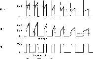
下面参照图5所示波形图说明图4直流马达的检测回转装置的动作。图5是用于说明图4的直流马达的检测回转装置动作的各部信号波形图。在图5中,图5A表示高速回转时和低速回转时检测回转用电刷BD1的输出信号SA1的波形,图5B表示噪音除去电路1A的输出信号SB1的波形,图5C表示比较器3的输出信号SC1的波形。Next, the operation of the detecting and rotating device of the DC motor in Fig. 4 will be described with reference to the waveform diagram shown in Fig. 5 . FIG. 5 is a signal waveform diagram of each part for explaining the operation of the detecting and turning device of the DC motor shown in FIG. 4 . In FIG. 5, FIG. 5A shows the waveform of the output signal SA1 of the brush BD1 for detection of rotation during high-speed rotation and low-speed rotation, FIG. 5B shows the waveform of the output signal SB1 of the noise removal circuit 1A, and FIG. 5C shows the output of the
包括检测回转用电刷BD1的直流马达M1通过串列开关SW1与输出电压Eo的直流驱动电源E1连接,使得该直流马达M1的检测回转用电刷BD1与噪音除去电路1A连接。在噪音除去电路1A中,如上所述,由例如稳压二极管等构成的定电压二极管ZD1与电阻R1和电容C1所构成的串接电路并联。定电压二极管ZD1对马达M1的转子线圈的自感应作用而引起的逆起动电压产生钳位作用。电阻R1及电容C1从两者连接点取出输出,构成除去高频成份的低通滤波器。从构成低通滤波器的电阻R1及电容C1的连接点取出的输出被供给比较器3的非反转输入端(+侧)。A DC motor M1 including a rotation detection brush BD1 is connected to a DC drive power supply E1 with an output voltage Eo through a serial switch SW1 such that the rotation detection brush BD1 of the DC motor M1 is connected to the noise removal circuit 1A. In the noise removing circuit 1A, as described above, the constant-voltage diode ZD1 composed of, for example, a Zener diode or the like is connected in parallel to the series circuit composed of the resistor R1 and the capacitor C1. The constant voltage diode ZD1 clamps the reverse starting voltage caused by the self-induction of the rotor coil of the motor M1. Resistor R1 and capacitor C1 take out the output from the connection point of the two, and constitute a low-pass filter that removes high-frequency components. The output taken out from the connection point of the resistor R1 and the capacitor C1 constituting the low-pass filter is supplied to the non-inverting input terminal (+ side) of the
若闭合开关SW1,来自驱动电源E1的直流电压供给直流马达M1,通过电极用电刷B11和B12,转子线圈被励磁,转子相对由永久磁铁等形成磁极的定子回转。通过该直流马达M1回转,在检测回转用电刷BD1产生大致呈脉冲状的电压信号SA1。从检测回转用电刷BD1输出的电压信号SA1的脉冲列的各脉冲的前缘部,即图5所示急剧上升波形是因转子线圈的自感应作用而发生的电压所引起的,这是由于切换与电刷相接的整流子的接片时,流过与各接片连接的转子线圈的电流大小瞬间变化,上述因转子线圈的自感应作用而发生的电压大小根据回转速度因流过线圈的电流大小而变化。When the switch SW1 is closed, the DC voltage from the driving power source E1 is supplied to the DC motor M1, and the rotor coil is excited by the electrode brushes B11 and B12, and the rotor rotates relative to the stator whose magnetic poles are formed by permanent magnets or the like. As the DC motor M1 rotates, a substantially pulsed voltage signal SA1 is generated in the rotation detection brush BD1. The leading edge of each pulse of the pulse train of the voltage signal SA1 output from the brush BD1 for detecting rotation, that is, the sharp rising waveform shown in FIG. 5 is caused by the voltage generated by the self-induction of the rotor coil. When switching the pieces of the commutator connected to the brushes, the magnitude of the current flowing through the rotor coil connected to each piece changes instantaneously, and the above-mentioned voltage generated by the self-induction of the rotor coil depends on the rotation speed due to the current flowing through the coil. varies with the size of the current.
各脉冲波形的倾斜部分是转子线圈中流过的电流及线圈的直流电阻成份所产生的电压以及线圈在磁场中回转所产生的感应电压的合成。高速回转时后者的感应电压居支配地位,低速回转时前者的电阻成份所引起的电压居支配地位。因此,该倾斜部分的倾斜角度如图5所示,回转越是低速,倾斜越平缓,接近平坦。The slope part of each pulse waveform is the synthesis of the current flowing in the rotor coil, the voltage generated by the DC resistance component of the coil, and the induced voltage generated by the coil rotating in the magnetic field. The induced voltage of the latter is dominant during high-speed rotation, and the voltage caused by the resistance component of the former is dominant during low-speed rotation. Therefore, the inclination angle of the inclined portion is shown in FIG. 5 , and the lower the turning speed, the gentler the inclination, and it is close to flat.
噪音除去电路1A的输出信号SB1的波形除去上述急剧波动波形以及因检测回转用电刷BD1与整流子接触所产生的机械噪音等高频噪音。比较器3比较该噪音除去电路1A的输出信号SB1的电压与从电位器VR1取出的例如约Eo/4的比较标准电压。因此,在该场合,作为比较器3的输出信号SC1只能出现电压Vcc的“H(高电平)”以及作为共同低电位、即接地电平的“L(低电平)”两种类电平之一,能得到稳定的矩形波。The waveform of the output signal SB1 of the noise removal circuit 1A removes high-frequency noise such as the abrupt fluctuation waveform and the mechanical noise generated by the contact between the brush BD1 for detecting rotation and the commutator. The
噪音除去电路1A可以根据使用直流马达特性、使用电力或信号处理电路系统的电压等构成,该噪音除去电路1A不一定是必要结构,根据使用直流马达特性、使用电力或信号处理电路系统的电压等有时也可以省略。The noise removal circuit 1A can be configured according to the characteristics of the DC motor used, the power used, or the voltage of the signal processing circuit system. Sometimes it can also be omitted.
第三实施例third embodiment
图6是示意性表示本发明第三实施例涉及的直流马达的检测回转装置构成的方框图,其是图3所示本发明第一实施例涉及的直流马达的检测回转装置的更具体的构成。6 is a block diagram schematically showing the structure of the detection and rotation device of the DC motor according to the third embodiment of the present invention, which is a more specific structure of the detection and rotation device of the DC motor according to the first embodiment of the present invention shown in FIG. 3 .
如图6所示,从驱动电源E1经开关SW1供给驱动电压Eo,驱动直流马达M1,检测直流马达M1的回转,在直流马达M1上设有一对电极用电刷B11、B12以及检测回转用电刷BD1。As shown in Figure 6, the drive voltage Eo is supplied from the drive power supply E1 through the switch SW1 to drive the DC motor M1 and detect the rotation of the DC motor M1. Brush BD1.
图6的直流马达的检测回转装置包括噪音除去电路1B、比较标准电压产生装置2B及比较器3。The detection rotation device of the DC motor in FIG.
噪音除去电路1B与图4所示噪音除去电路1A完全相同,设有定电压二极管ZD1、电阻R1及电容C1,噪音除去电路1B除去检测回转用电刷BD1的检测信号中的急剧波动状波形等噪音成份,供给比较器3。The
定电压二极管ZD1由例如稳压二极管等构成,连接在检测回转用电刷BD1与驱动电源E1的共同低电位侧之间。电阻R1及电容C1顺序串接,该串接电路将电阻R1连接在检测回转用电刷BD1侧,将电容C1连接在驱动电源E1的共同低电位侧,上述串接电路与定电压二极管ZD1并联,连接在检测回转用电刷BD1与驱动电源E1的共同低电位(接地电位)之间。电容C1的两端,即该电容C1和电阻R1的连接点与驱动电源E1的共同低电位之间的电压供给比较器3的非反转输入端(+侧)。The constant voltage diode ZD1 is composed of, for example, a Zener diode, and is connected between the rotation detection brush BD1 and the common low potential side of the drive power source E1. Resistor R1 and capacitor C1 are sequentially connected in series. In this series connection circuit, resistor R1 is connected to the brush BD1 side for detecting rotation, and capacitor C1 is connected to the common low potential side of driving power E1. The above series connection circuit is connected in parallel with constant voltage diode ZD1 , is connected between the common low potential (ground potential) of the detection rotation brush BD1 and the drive power supply E1. The voltage between both ends of the capacitor C1 , that is, the connection point of the capacitor C1 and the resistor R1 and the common low potential of the driving power supply E1 is supplied to the non-inverting input terminal (+ side) of the
比较标准电压产生装置2B产生比较标准电压,供给比较器3,以便将检测回转用电刷BD1的检测信号变换成与回转速度相对应的脉冲周期及脉冲振幅的脉冲列,其与图4的比较标准电压产生装置2A大致相同,由电位器VR2构成,但电位器VR2的固定侧两端分别与直流马达M1的电极用电刷B11、B12连接,该电位器VR2的可动端与共同低电位之间的电压,例如Eo/4供给比较器3的反转输入端(-侧)。The comparison standard
比较器3具有与图3和图4场合大致相同的结构,将通过噪音除去电路1B从检测回转用电刷BD1的检测信号除去噪音成份的信号供给比较器3的非反转输入端(+侧),将比较标准电压产生装置2B产生的比较标准电压(Eo/4)供给比较器3的反转输入端(-侧),对两者进行比较。若噪音除去电路1B的输出超过比较标准电压(Eo/4),则成为电源电压Vcc,即“H(高电平)”,若噪音除去电路1B的输出为比较标准电压(Eo/4)以下,则成为共同低电位,即“L(低电平)”,输出与回转速度相对应的脉冲周期及脉冲振幅的脉冲列。The
下面参照图7所示波形图说明图6直流马达的检测回转装置的动作,图7是用于说明图6的直流马达的检测回转装置动作的各部信号波形图。在图7中,图7A表示直流马达M1的驱动电压Eo逐渐降低时的检测回转用电刷BD1的输出信号SA2的波形,图7B表示噪音除去电路1B的输出信号SB2的波形,图7C表示比较器3的输出信号SC2的波形。Next, the operation of the detection and rotation device of the DC motor in FIG. 6 will be described with reference to the waveform diagram shown in FIG. 7. FIG. In FIG. 7, FIG. 7A shows the waveform of the output signal SA2 of the detection rotation brush BD1 when the driving voltage Eo of the DC motor M1 gradually decreases, FIG. 7B shows the waveform of the output signal SB2 of the
图6与图4结构的不同点在于将比较标准电压产生装置2B的电源与直流马达M1的驱动电源设为同一电源。The difference between the structure of FIG. 6 and that of FIG. 4 is that the power supply of the comparison
直流马达M1的驱动电压Eo逐渐降低时,各部电压如图7所示,检测回转用电刷BD1的输出信号SA2及噪音除去电路1B的输出信号SB2的电压随着Eo的变化逐渐降低。这时,直流马达M1的负荷扭矩若为一定,回转速度也逐渐变慢。When the driving voltage Eo of the DC motor M1 gradually decreases, the voltages of the various parts, as shown in FIG. At this time, if the load torque of the DC motor M1 is constant, the rotation speed will gradually decrease.
但是,作为比较标准电压的电位器VR2的输出电压也与Eo成比例下降,比较器3的反转输入与非反转输入的大小关系、即比率大致保持一定。因此,尽管直流马达M1的端子电压Eo变化,比较器3的输出信号SC2仍可得到稳定的矩形波。However, the output voltage of the potentiometer VR2, which is a comparison standard voltage, also drops in proportion to Eo, and the magnitude relationship between the inverting input and the non-inverting input of the
在使用直流马达的装置中,经常通过使施加到直流马达的电压变化控制回转速度,换句话说,控制直流马达的发生扭矩。另一方面,在电源使用电池的装置中,直流马达的端子电压频繁变化。上述本发明第三实施例的如图6所示的直流马达的检测回转装置即使直流马达的端子电压变化,也能得到稳定的检测回转信号。In devices using a DC motor, the rotational speed is often controlled by varying the voltage applied to the DC motor, in other words, the torque generated by the DC motor is controlled. On the other hand, in a device using a battery as a power source, the terminal voltage of the DC motor changes frequently. The detection rotation device of the DC motor shown in FIG. 6 according to the third embodiment of the present invention can obtain a stable detection rotation signal even if the terminal voltage of the DC motor changes.
第四实施例Fourth embodiment
图8是示意性表示本发明第四实施例涉及的直流马达的回转控制装置构成的方框图,图8的直流马达的回转控制装置除直流马达M2和驱动电源电路E2之外,还包括马达驱动电路5、噪音除去电路6、比较标准电压产生装置7、比较标准电压选择装置8、比较器9及马达控制电路10。8 is a block diagram schematically showing the configuration of a rotation control device for a DC motor according to a fourth embodiment of the present invention. The rotation control device for a DC motor in FIG. 8 further includes a motor drive circuit in addition to a DC motor M2 and a drive power supply circuit E2. 5.
如图8所示,从驱动电源电路E2通过马达驱动电路5供给驱动电力,驱动直流马达M2,直流马达的回转控制装置控制直流马达M2的回转,在直流马达M2上设有一对电极用电刷B21、B22以及检测回转用电刷BD2。As shown in Figure 8, drive power is supplied from the drive power supply circuit E2 through the motor drive circuit 5 to drive the DC motor M2. The rotation control device of the DC motor controls the rotation of the DC motor M2. A pair of electrode brushes are provided on the DC motor M2. B21, B22 and brush BD2 for detecting rotation.
在驱动电源电路E2的正负输出端之间连接马达驱动电路5,该马达驱动电路5包括开关部,其由晶体管Q1、Q2、Q3及Q4构成电桥电路形成。A motor drive circuit 5 is connected between the positive and negative output terminals of the drive power supply circuit E2, and the motor drive circuit 5 includes a switch part formed by a bridge circuit composed of transistors Q1, Q2, Q3 and Q4.
在马达驱动电路5的输出端子的一方,即晶体管Q1的集电极与晶体管Q3的集电极的连接点连接有直流马达M2的一方的电极用电刷B21,在马达驱动电路5的输出端子的另一方,即晶体管Q2的集电极与晶体管Q4的集电极的连接点连接有直流马达M2的另一方的电极用电刷B22。One of the output terminals of the motor drive circuit 5, that is, the connection point between the collector of the transistor Q1 and the collector of the transistor Q3, is connected to a brush B21 for one electrode of the DC motor M2. One side, that is, the connection point between the collector of the transistor Q2 and the collector of the transistor Q4 is connected to the other electrode brush B22 of the DC motor M2 .
马达驱动电路5的控制输入端与马达控制电路10连接,根据来自马达控制电路10的马达控制信号控制晶体管Q1、Q2、Q3及Q4的接通或断开,控制直流马达M2的正转、逆转和停止等。The control input terminal of the motor drive circuit 5 is connected to the motor control circuit 10, and the transistors Q1, Q2, Q3, and Q4 are controlled to be turned on or off according to the motor control signal from the motor control circuit 10, and the forward rotation and reverse rotation of the DC motor M2 are controlled. and stop waiting.
直流马达M2的检测回转用电刷BD2的输出输入到噪音除去电路6,该噪音除去电路6的输出端与比较器9的非反转输入端(+侧)相连接。The output of the brush BD2 for detecting rotation of the DC motor M2 is input to the
另一方面,比较标准电压产生装置7由两个电位器VR21和VR22串接构成,电位器VR21和VR22串接电路与马达驱动电路5并联连接在驱动电源电路E2上。On the other hand, the comparative standard
也就是说,各电位器VR21和VR22的输出产生与电源电压Eo成比例的电压,例如设定电位器VR21相对从可动端到共同低电位取出大约3Eo/4的电压,电位器VR22相对从可动端到共同低电位取出大约Eo/4的电压。That is to say, the output of each potentiometer VR21 and VR22 produces a voltage proportional to the power supply voltage Eo. For example, the setting potentiometer VR21 takes out a voltage of about 3Eo/4 from the movable end to the common low potential, and the potentiometer VR22 is relatively from the common low potential. The movable end takes out a voltage of about Eo/4 to the common low potential.
比较标准电压选择装置8由两个模拟开关ASW1、ASW2及一个变换器INV构成,电位器VR21的从可动端取出的输出与模拟开关ASW1的输入端连接,电位器VR22的从可动端取出的输出与模拟开关ASW2的输入端连接,模拟开关ASW1、ASW2的输出端与比较器9的反转输入端(-侧)连接。来自马达控制电路10的控制信号作为比较标准电压选择信号通过变换器INV被反转供给模拟开关ASW1的控制端子,同时,该比较标准电压选择信号直接供给模拟开关ASW2的控制端子。The comparative standard voltage selection device 8 is composed of two analog switches ASW1, ASW2 and an inverter INV. The output of the potentiometer VR21 taken from the movable end is connected to the input end of the analog switch ASW1, and the potentiometer VR22 is taken out from the movable end. The output of the analog switch ASW2 is connected to the input terminal, and the output terminals of the analog switches ASW1 and ASW2 are connected to the inverting input terminal (-side) of the comparator 9 . The control signal from the motor control circuit 10 is inverted as a comparison standard voltage selection signal to the control terminal of the analog switch ASW1 through the inverter INV, and the comparison standard voltage selection signal is directly supplied to the control terminal of the analog switch ASW2.
也就是说,根据来自马达控制电路10的比较标准电压选择信号控制模拟开关ASW1和ASW2中一方接通,另一方断开,仅将比较标准电压产生装置7的电位器VR21和VR22中一方输出供给比较器9的反转输入端。比较器9的输出供给马达控制电路10。马达控制电路10使用微机等构成,接收到比较器9的输出以及根据需要来自外部的控制指示,分别产生对马达驱动电路5的马达控制信号以及对比较标准电压选择装置8的比较标准电压选择信号,供给马达驱动电路5和比较标准电压选择装置8。That is to say, according to the comparison standard voltage selection signal from the motor control circuit 10, one of the analog switches ASW1 and ASW2 is controlled to be turned on and the other is turned off, and only one of the potentiometers VR21 and VR22 of the comparison standard
根据控制端子的信号状态是“H”还是“L”模拟开关ASW1和ASW2进行接通或断开动作,在接通状态下,输入到输入端子的电压原样地输出到输出端子,在断开状态下,输入到输入端子的电压不输出到输出端子。According to whether the signal state of the control terminal is "H" or "L", the analog switches ASW1 and ASW2 are turned on or off. In the on state, the voltage input to the input terminal is output to the output terminal as it is, and in the off state In this case, the voltage input to the input terminal is not output to the output terminal.
具体地说,例如,控制端子的信号状态是“H”时,成为接通状态,使输入信号通过,控制端子的信号状态是“L”时,成为断开,呈高阻抗状态。Specifically, for example, when the signal state of the control terminal is "H", it is turned on and the input signal is passed through, and when the signal state of the control terminal is "L", it is turned off and is in a high impedance state.
下面参照图9所示波形图说明图8直流马达的回转控制装置的动作。Next, the operation of the rotation control device of the DC motor in FIG. 8 will be described with reference to the waveform diagram shown in FIG. 9 .
图9是用于说明图8的直流马达的回转控制装置动作的各部信号波形图。在图9中,图9A表示直流马达M2朝顺时钟方向(CW)回转时和朝逆时钟方向(CCW)回转时的比较标准电压选择信号的波形,图9B表示比较器9的反转输入端的输入信号、即检测回转用电刷的输出信号的波形,图9C表示比较器9的输出信号的波形。FIG. 9 is a signal waveform diagram of each part for explaining the operation of the rotation control device for the DC motor shown in FIG. 8 . In FIG. 9, FIG. 9A shows the waveform of the comparison standard voltage selection signal when the DC motor M2 turns clockwise (CW) and counterclockwise (CCW), and FIG. 9B shows the waveform of the inverting input terminal of the comparator 9. The input signal, that is, the waveform of the output signal of the brush for detection of rotation, FIG. 9C shows the waveform of the output signal of the comparator 9 .
若从马达控制电路10输出马达控制信号,马达驱动电路5的晶体管Q1及晶体管Q4接通,直流马达M2朝顺时钟方向回转。与此同时,从马达控制电路10输出“H”作为比较标准电压选择信号。直流马达M2的检测回转用电刷BD2的电压通过噪音除去电路6输入到比较器9的非反转输入端。When the motor control signal is output from the motor control circuit 10, the transistors Q1 and Q4 of the motor drive circuit 5 are turned on, and the DC motor M2 rotates clockwise. At the same time, "H" is output from the motor control circuit 10 as a comparison standard voltage selection signal. The voltage of the rotation detection brush BD2 of the DC motor M2 is input to the non-inverting input terminal of the comparator 9 through the
另一方面,比较标准电压输入比较器9的反转输入端。这种场合,比较标准电压选择信号为“H”,模拟开关ASW1断开,模拟开关ASW2接通,所以,选择电位器VR22设定的电压Eo/4作为比较标准电压。因此,比较器9的输出成为图9A所示的矩形波。On the other hand, the comparison standard voltage is input to the inverting input terminal of the comparator 9 . In this case, the comparison standard voltage selection signal is "H", the analog switch ASW1 is turned off, and the analog switch ASW2 is turned on, so the voltage Eo/4 set by the potentiometer VR22 is selected as the comparison standard voltage. Therefore, the output of the comparator 9 becomes a rectangular wave as shown in FIG. 9A.
接着,从马达控制电路10输出马达控制信号,使得马达驱动电路5的晶体管Q2及晶体管Q3接通,与此同时,从马达控制电路10输出“L”作为比较标准电压选择信号。这样,直流马达M2朝逆时钟方向回转,根据检测回转用电刷BD2的检测电压在比较器9的非反转输入端成为图9B所示波形。Next, the motor control signal is output from the motor control circuit 10, so that the transistors Q2 and Q3 of the motor drive circuit 5 are turned on, and at the same time, "L" is output from the motor control circuit 10 as a comparison standard voltage selection signal. Thus, the DC motor M2 rotates in the counterclockwise direction, and the waveform shown in FIG. 9B is obtained at the non-inverting input terminal of the comparator 9 based on the detection voltage of the rotation detection brush BD2.
根据比较标准电压选择信号,模拟开关ASW1接通,模拟开关ASW2断开,所以,选择电位器VR21设定的电压3Eo/4作为比较标准电压。因此,比较器9的输出成为图9B所示的矩形波。According to the comparison standard voltage selection signal, the analog switch ASW1 is turned on, and the analog switch ASW2 is turned off, so the voltage 3Eo/4 set by the potentiometer VR21 is selected as the comparison standard voltage. Therefore, the output of the comparator 9 becomes a rectangular wave as shown in FIG. 9B.
这样,在比较器9的输出中,理应得到脉冲列作为直流马达M2的回转信号,但是,例如使用马达的检测回转用电刷与电极用电刷的角度为40度场合,在顺时钟方向回转时成为占空系数1/3的脉冲列,在逆时钟方向回转时成为占空系数2/3的脉冲列。In this way, in the output of the comparator 9, the pulse train should be obtained as the rotation signal of the DC motor M2. However, for example, when the angle between the detection rotation brush and the electrode brush of the motor is 40 degrees, the rotation in the clockwise direction When turning in the counterclockwise direction, it becomes a pulse train with a duty factor of 1/3, and when it rotates counterclockwise, it becomes a pulse train with a duty factor of 2/3.
根据上述结构,对于直流马达M2的两方向回转能得到稳定的回转信号,能对直流马达M2合适地进行回转控制。According to the above configuration, stable rotation signals can be obtained for the rotation of the DC motor M2 in both directions, and the rotation control of the DC motor M2 can be appropriately performed.
第五实施例fifth embodiment
图10是示意性表示本发明第五实施例涉及的直流马达的回转控制装置构成的方框图,图10的直流马达的回转控制装置与图8装置大致相同,图10的马达驱动电路5A代替图8的马达驱动电路5,图10的马达控制电路10A代替图8的马达控制电路10。10 is a block diagram schematically showing the configuration of a rotation control device for a DC motor according to a fifth embodiment of the present invention. The rotation control device for a DC motor in FIG. 10 is substantially the same as the device in FIG. 8 , and the motor drive circuit 5A in FIG. The motor drive circuit 5 of FIG. 10 replaces the motor control circuit 10 of FIG. 8 with a motor control circuit 10A of FIG. 10 .
马达控制电路10A使用微机等构成,附加脉冲间隔检测装置13A、回转速度计算装置14A、回转速度比较装置15A各功能。The motor control circuit 10A is constituted by using a microcomputer or the like, and functions of a pulse interval detection device 13A, a rotation speed calculation device 14A, and a rotation speed comparison device 15A are added.
脉冲间隔检测装置13A检测脉冲间隔TM。在脉冲间隔检测装置13A中,脉冲间隔TM的检测方法如图13A和图13B所示,标准时钟脉冲频率比从比较器9输出的直流马达M2的回转信号脉冲频率充分高,以该标准时钟脉冲对回转信号脉冲一周期进行计数,以下式进行计算:TM=Tax×计数脉冲数。The pulse interval detecting means 13A detects the pulse interval TM. In the pulse interval detection device 13A, the detection method of the pulse interval TM is as shown in FIGS. 13A and 13B. The standard clock pulse frequency is sufficiently higher than the pulse frequency of the rotation signal of the DC motor M2 output from the comparator 9, and the standard clock pulse frequency Count one cycle of the rotation signal pulse, and calculate it with the following formula: TM=Tax×number of counting pulses.
根据脉冲间隔检测装置13A检测到的脉冲间隔TM、回转速度计算装置14A计算直流马达M2的回转速度。即由脉冲间隔检测装置13A所得的回转信号脉冲的周期(回转信号脉冲间隔)为TM场合,通过回转速度计算装置14A计算直流马达M2的回转速度,三极马达场合,以60/3TM[rpm]计算。上述标准时钟脉冲由内藏在构成马达控制电路10A的微机等中的标准时钟脉冲振荡器产生。回转速度比较装置15A将由回转速度计算装置14A计算而得的回转速度N1(现在)与目标速度N2(目标)进行比较,产生使直流马达得到目标速度N2(目标)的马达控制信号。Based on the pulse interval TM detected by the pulse interval detecting means 13A, the rotational speed calculating means 14A calculates the rotational speed of the DC motor M2. That is, when the period of the rotation signal pulse obtained by the pulse interval detection device 13A (the rotation signal pulse interval) is TM, the rotation speed of the DC motor M2 is calculated by the rotation speed calculation device 14A, and in the case of a three-pole motor, it is 60/3TM [rpm] calculate. The above-mentioned standard clock is generated by a standard clock oscillator built in a microcomputer or the like constituting the motor control circuit 10A. The rotational speed comparator 15A compares the rotational speed N1 (current) calculated by the rotational speed calculation means 14A with the target speed N2 (target), and generates a motor control signal for the DC motor to obtain the target speed N2 (target).
在本实施例中,马达驱动电路5A通过激励器DA1、DA2、DA3及DA4分别使晶体管Q1、Q2、Q3及Q4实现接通或断开动作,上述激励器DA1、DA2、DA3及DA4响应由马达控制电路10A的回转速度比较装置15A产生的马达控制信号动作。In this embodiment, the motor driving circuit 5A makes the transistors Q1, Q2, Q3 and Q4 turn on or off through the exciters DA1, DA2, DA3 and DA4 respectively, and the above-mentioned exciters DA1, DA2, DA3 and DA4 respond to The motor control signal generated by the rotational speed comparator 15A of the motor control circuit 10A operates.
下面参照图11所示主要部分的流程图及图12所示波形图说明图10所示直流马达的回转控制装置的动作。Next, the operation of the rotation control device for the DC motor shown in FIG. 10 will be described with reference to the flow chart of main parts shown in FIG. 11 and the waveform diagram shown in FIG. 12 .
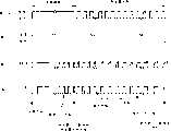
图12是用于说明图10的直流马达的回转控制装置动作的各部信号波形图。在图12中,表示通过斩波器控制使直流马达回转状态下,在给予马达停止信号前将直流马达M2的回转速度保持一定场合,图12A表示晶体管Q1的接通/断开控制信号的波形,图12B表示晶体管Q4的接通/断开控制信号的波形,图12C表示比较器9的非反转输入端的输入信号的波形,图12D表示比较器9的输出信号的波形。FIG. 12 is a signal waveform diagram of each part for explaining the operation of the rotation control device for the DC motor shown in FIG. 10 . In FIG. 12, it shows the case where the DC motor M2 is kept at a constant rotation speed before a motor stop signal is given under chopper control to rotate the DC motor. FIG. 12A shows the waveform of the ON/OFF control signal of the transistor Q1. , FIG. 12B shows the waveform of the on/off control signal of the transistor Q4, FIG. 12C shows the waveform of the input signal of the non-inverting input terminal of the comparator 9, and FIG. 12D shows the waveform of the output signal of the comparator 9.
在直流马达M2回转状态下,响应直流马达M2的回转在比较器9的输出信号中出现直流马达M2的回转信号脉冲。In the rotation state of the DC motor M2, a rotation signal pulse of the DC motor M2 appears in the output signal of the comparator 9 in response to the rotation of the DC motor M2.
在该第五实施例中,马达控制电路10A反复使向直流马达M2的通电一时中断(反复接通断开),即进行所谓斩波器控制,通过改变斩波器控制的占空系数,控制直流马达M2的回转速度。即根据直流马达M2的回转信号,计算回转速度,回转速度比预先设定的目标速度快场合,减小占空系数(一周期中接通时间的比例),使其减速;回转速度比预先设定的目标速度慢场合,增大占空系数,使其加速,使得直流马达M2的回转速度成为目标回转速度。In this fifth embodiment, the motor control circuit 10A repeatedly temporarily interrupts the power supply to the DC motor M2 (repeatedly turning on and off), that is, performs so-called chopper control. By changing the duty factor of the chopper control, control The rotational speed of the DC motor M2. That is, according to the rotation signal of the DC motor M2, the rotation speed is calculated. If the rotation speed is faster than the preset target speed, the duty factor (the ratio of the on-time in one cycle) is reduced to decelerate it; the rotation speed is faster than the preset target speed. If the fixed target speed is slow, increase the duty factor and accelerate it so that the rotation speed of the DC motor M2 becomes the target rotation speed.
参照图11所示主要部分的流程图说明图10所示直流马达的回转控制装置的动作。在步骤S11判断有无马达开始回转信号,若有马达开始回转信号(步骤S11的“是”),则进入步骤S12,以“H”电平输出比较标准电压选择信号,在步骤S13,马达开始顺时钟方向回转(输出Q1、Q4接通信号),然后进入步骤S14。The operation of the rotation control device for the DC motor shown in FIG. 10 will be described with reference to the flowchart of the main part shown in FIG. 11 . In step S11, it is judged whether there is a motor start rotation signal, if there is a motor start rotation signal ("Yes" in step S11), then enter step S12, and output a comparison standard voltage selection signal with "H" level, in step S13, the motor starts Turn clockwise (output Q1, Q4 on signal), and then enter step S14.
在步骤S14,马达控制电路10A通过脉冲间隔检测装置13A从比较器9的回转信号脉冲检测脉冲间隔TM,接着进入步骤S15,根据该脉冲间隔检测装置13A的检测结果,通过回转速度计算装置14A计算此时的直流马达M2的回转速度N1。In step S14, the motor control circuit 10A detects the pulse interval TM from the rotation signal pulse of the comparator 9 through the pulse interval detection device 13A, then proceeds to step S15, and calculates the rotation speed calculation device 14A according to the detection result of the pulse interval detection device 13A. The rotation speed N1 of the DC motor M2 at this time.
在步骤S16,马达控制电路10A的回转速度比较装置15A将通过回转速度计算装置14A计算而得的直流马达M2的最新回转速度N1(现在)与目标速度N2(目标)进行比较,判断N1是否小于N2,该目标速度N2有时也可以不是特定回转速度值,而是特定回转速度范围。若N1不小于N2(步骤S16的“否”),则进入步骤S17,马达控制电路10A的回转速度比较装置15A判断N1是否大于N2。In step S16, the rotational speed comparator 15A of the motor control circuit 10A compares the latest rotational speed N1 (current) of the DC motor M2 calculated by the rotational speed calculating means 14A with the target speed N2 (target), and determines whether N1 is less than N2, the target speed N2 may not be a specific rotation speed value, but may be a specific rotation speed range. If N1 is not smaller than N2 ("No" in step S16), then go to step S17, and the rotation speed comparator 15A of the motor control circuit 10A judges whether N1 is larger than N2.
若N1不大于N2(步骤S17的“否”),则N1等于N2,于是,在步骤S18,马达控制电路10A继续以现在的占空系数进行斩流器控制。并且在步骤S19马达控制电路10A判断有否马达停止信号,若有马达停止信号(步骤S19的“是”),则进入步骤S20,输出马达断开信号(输出Q1、Q4断开信号),进入步骤S21,使直流马达M2停止。若在步骤S19判断无马达停止信号(步骤S19的“否”),则回到步骤S14,马达控制电路10A继续直流马达M2的斩波器控制。If N1 is not greater than N2 ("No" in step S17), then N1 is equal to N2, and then, in step S18, the motor control circuit 10A continues to perform chopper control at the current duty factor. And in step S19 motor control circuit 10A judges whether there is a motor stop signal, if there is a motor stop signal ("Yes" in step S19), then enter step S20, output a motor disconnect signal (output Q1, Q4 disconnect signal), enter Step S21, stop the DC motor M2. If it is judged in step S19 that there is no motor stop signal ("No" in step S19), the process returns to step S14, and the motor control circuit 10A continues the chopper control of the DC motor M2.
若在步骤S16判断N1小于N2场合(步骤S16的“是”),则进入步骤S22,判别上回占空系数变更后是否已经过所定时间,在此前完全没有变更过占空系数场合或上回占空系数变更后已经过所定时间场合(步骤S22的“是”),则进入步骤S23,增大斩波器控制的占空系数,然后移到步骤S19。若在步骤S22,判别上回占空系数变更后没有经过所定时间场合(步骤S22的“否”),则马达控制电路10A不变更斩波器控制的占空系数,直接移到步骤S19。If it is judged in step S16 that N1 is less than N2 ("yes" in step S16), then enter step S22 to determine whether the predetermined time has passed after the duty cycle was changed last time. If the predetermined time has elapsed since the duty factor was changed (YES in step S22), go to step S23 to increase the duty factor of the chopper control, and then move to step S19. If it is determined in step S22 that the predetermined time has not elapsed since the previous duty cycle change ("No" in step S22), the motor control circuit 10A directly moves to step S19 without changing the duty cycle of the chopper control.
若在步骤S17判断N1大于N2场合(步骤S17的“是”),则进入步骤S24,判别上回占空系数变更后是否已经过所定时间,在此前完全没有变更过占空系数场合或上回占空系数变更后已经过所定时间场合(步骤S24的“是”),则进入步骤S25,减小斩波器控制的占空系数,然后移到步骤S19。若在步骤S24,判别上回占空系数变更后没有经过所定时间场合(步骤S24的“否”),则马达控制电路10A不变更斩波器控制的占空系数,直接移到步骤S19。If it is judged in step S17 that N1 is greater than N2 ("yes" in step S17), then enter step S24 to determine whether the predetermined time has passed after the duty cycle was changed last time. If the predetermined time has elapsed since the duty factor was changed ("Yes" in step S24), go to step S25 to reduce the duty factor of the chopper control, and then move to step S19. If it is determined in step S24 that the predetermined time has not elapsed since the previous duty cycle change ("No" in step S24), the motor control circuit 10A directly moves to step S19 without changing the duty cycle of the chopper control.
关于上述占空系数变更后没有经过所定时间场合马达控制电路10A不变更斩波器控制的占空系数,这是考虑到直流马达M2的回转速度在变更占空系数后有时不是马上改变,存在响应滞后的问题。因此,也可以使用斩波器控制的所定周期或回转信号脉冲的所定计数代替上述所定时间。Regarding the case where the motor control circuit 10A does not change the duty ratio of the chopper control when the above-mentioned duty ratio has not been changed, this is because the rotation speed of the DC motor M2 may not change immediately after the duty ratio is changed, and there is a response. Lag problem. Therefore, instead of the above-mentioned predetermined time, a predetermined period of chopper control or a predetermined count of slewing signal pulses may also be used.
如图12所示,在回转速度N1(现在)与目标速度N2(目标)一致状态下,马达控制电路10A控制晶体管Q1以一定周期一定占空系数反复接通断开,控制晶体管Q4常时接通。As shown in Fig. 12, when the rotation speed N1 (current) is consistent with the target speed N2 (target), the motor control circuit 10A controls the transistor Q1 to be turned on and off repeatedly at a certain cycle and a certain duty factor, and the control transistor Q4 is always connected Pass.
若判断回转速度N1(现在)的检测结果比目标速度N2(目标)慢,马达控制电路10A与此相对应,对马达驱动电路5A给予使斩波器控制的占空系数变大的马达控制信号。具体地说,例如,在晶体管Q1周期性的接通/断开动作中,使得一周期中接通期间与断开期间之比例相对变大。例如,若当初以50%占空系数进行控制,则变更为以75%占空系数进行控制,再次检测回转速度。If it is judged that the detection result of the rotation speed N1 (current) is slower than the target speed N2 (target), the motor control circuit 10A responds to this, and supplies a motor control signal to increase the duty ratio of the chopper control to the motor drive circuit 5A. . Specifically, for example, in the periodic on/off operation of the transistor Q1, the ratio of the on-period to the off-period in one cycle is relatively large. For example, if control is performed at a duty factor of 50% initially, it is changed to control at a duty factor of 75%, and the rotational speed is detected again.
若判断回转速度N1(现在)的检测结果比目标速度N2(目标)快,马达控制电路10A与此相对应,对马达驱动电路5A给予使斩波器控制的占空系数变小的马达控制信号。具体地说,例如,在晶体管Q1周期性的接通/断开动作中,使得一周期中接通期间与断开期间之比例相对变小。例如,若以75%占空系数进行控制场合,则变更为以50%占空系数进行控制,再次检测回转速度。经过上述控制后,若判断回转速度N1(现在)的检测结果仍比目标速度N2(目标)快,马达控制电路10A与此相对应,对马达驱动电路5A给予使斩波器控制的占空系数进一步变小的马达控制信号。具体地说,例如,在晶体管Q1周期性的接通/断开动作中,使得一周期中接通期间与断开期间之比例进一步变小。例如,若以50%占空系数进行控制场合,则变更为以25%占空系数进行控制,再次检测回转速度。If it is judged that the detection result of the rotation speed N1 (current) is faster than the target speed N2 (target), the motor control circuit 10A responds to this, and gives the motor drive circuit 5A a motor control signal for reducing the duty ratio of the chopper control. . Specifically, for example, in the periodic on/off operation of the transistor Q1, the ratio of the on-period to the off-period in one cycle is relatively reduced. For example, if the control is performed with a duty factor of 75%, it is changed to control with a duty factor of 50%, and the rotation speed is detected again. After the above control, if it is judged that the detection result of the rotation speed N1 (current) is still faster than the target speed N2 (target), the motor control circuit 10A corresponds to this, and gives the motor drive circuit 5A a duty factor for chopper control. Further smaller motor control signal. Specifically, for example, in the periodic on/off operation of the transistor Q1, the ratio of the on-period to the off-period in one cycle is further reduced. For example, if the control is performed with a duty factor of 50%, it is changed to control with a duty factor of 25%, and the rotation speed is detected again.
在此,说明进行斩波器控制时的检测回转用电刷BD2的输出电压。通常即直流控制时,波形几乎不产生电压的低电压部分设为L部,产生电压逐渐增加的右阶梯上升电压波形的部分设为H部,在L部,即使是斩波器控制区间,由于晶体管Q4常时接通,电极用电刷B22大致为共同低电位(接地电平),与电极用电刷B22成40度角的检测回转用电刷BD2由于通过整流子与电极用电刷B22形成短路,所以也大致为共同低电位。关于H部,请参照例如图12的A部,由于晶体管Q1断开,直流马达M2的电极(电极用电刷B21和B22)上不施加外部电压。但是,如上所述,若直流马达M2回转,转子线圈中因感应起电产生电压,在H部仍然出现电压(若回转速度慢,产生电压小,有时难以检出)。Here, the detection of the output voltage of the rotation brush BD2 at the time of chopper control will be described. Normally, that is, during DC control, the low-voltage part of the waveform that generates almost no voltage is set as the L part, and the part that generates the right step-up voltage waveform that gradually increases the voltage is set as the H part. In the L part, even in the chopper control zone, due to Transistor Q4 is always on, the electrode brush B22 is roughly at a common low potential (ground level), and the detection rotation brush BD2 at an angle of 40 degrees to the electrode brush B22 passes through the commutator and the electrode brush B22 A short circuit is formed, so it is also roughly a common low potential. As for part H, please refer to part A of FIG. 12 for example. Since the transistor Q1 is turned off, no external voltage is applied to the electrodes (electrode brushes B21 and B22 ) of the DC motor M2. However, as mentioned above, if the DC motor M2 rotates, a voltage is generated in the rotor coil due to induction, and the voltage still appears in the H portion (if the rotation speed is slow, the generated voltage is small, and sometimes it is difficult to detect).
在本实施例的直流马达的回转控制装置中,通过斩波器控制直流马达M2,检测而得的回转速度N1(现在)若小于目标速度(目标),为了提高回转速度,增大斩波器控制中的占空系数,使回转速度上升。检测而得的回转速度N1(现在)若大于目标速度(目标),为了降低回转速度,减小斩波器控制中的占空系数,使回转速度下降。In the rotation control device of the DC motor of this embodiment, the DC motor M2 is controlled by the chopper, and if the detected rotation speed N1 (now) is lower than the target speed (target), in order to increase the rotation speed, the chopper is increased. The duty factor in the control makes the rotation speed increase. If the detected rotation speed N1 (current) is higher than the target speed (target), in order to reduce the rotation speed, the duty factor in the chopper control is reduced to lower the rotation speed.
第六实施例Sixth embodiment
图14是示意性表示本发明第六实施例涉及的直流马达的回转控制装置构成的方框图,图14的直流马达的回转控制装置与图10装置大致相同,图14的马达驱动电路5B代替图10的马达驱动电路5A,图14的马达控制电路10B代替图10的马达控制电路10A。FIG. 14 is a block diagram schematically showing the configuration of a rotation control device for a DC motor according to a sixth embodiment of the present invention. The rotation control device for a DC motor in FIG. 14 is substantially the same as the device in FIG. 10 , and the
即图14的直流马达的回转控制装置的基本结构与图10所示第五实施例装置大致相同,与图10的直流马达的回转控制装置的不同点在于马达驱动电路5B的内部结构,在由晶体管Q1-Q4所构成的电桥电路的前段设有译码器DEC1。这种场合,在马达控制电路10B中,从回转速度比较装置15B供给一位的输入信号IN1和IN2作为马达控制信号,通过将上述输入信号IN1和IN2组合成二位信号,如图15真值表所示,可实现马达顺时钟方向回转、逆时钟方向回转、制动(分流)及停止四种状态。That is, the basic structure of the rotation control device of the DC motor shown in FIG. 14 is substantially the same as that of the fifth embodiment device shown in FIG. A decoder DEC1 is provided at the front stage of the bridge circuit composed of transistors Q1-Q4. In this case, in the
这种马达驱动电路5B由于控制信号少能广泛用于控制直流马达的回转。这种场合,马达驱动电路5B通过译码器DEC1的输出OUT1、OUT2、OUT3、OUT4分别使晶体管Q1、Q2、Q3、Q4接通或断开。Such a
马达控制电路10B与图10中马达控制电路10A大致相同,使用微机等构成,同样相应包括脉冲间隔检测装置13B、回转速度计算装置14B及回转速度比较装置15B,但回转速度比较装置15B结构与图10中回转速度比较装置15A有若干不同之处。The
回转速度比较装置15B将由回转速度计算装置14B计算而得的回转速度N1(现在)与目标速度N2(目标)进行比较,产生马达控制信号,以便通过组合直流控制与斩波器控制,使直流马达得到目标速度N2(目标)。斩波器控制期间,忽略回转速度N1(现在)与目标速度N2(目标)的比较结果,或忽略脉冲间隔检测装置13B和回转速度计算装置14B的检测回转速度结果,不反映到供给马达驱动电路5B的马达控制信号中。The rotation speed comparison means 15B compares the rotation speed N1 (now) calculated by the rotation speed calculation means 14B with the target speed N2 (target) to generate a motor control signal so that the DC motor can be driven by combining the DC control and the chopper control. The target speed N2 (target) is obtained. During chopper control, the comparison result of the rotation speed N1 (now) and the target speed N2 (target), or the detected rotation speed results of the pulse interval detection means 13B and the rotation speed calculation means 14B are ignored, and are not reflected in the supply motor drive circuit. 5B in the motor control signal.
下面参照图16所示主要部分的流程图及图17所示波形图说明图14所示直流马达的回转控制装置的动作。Next, the operation of the rotation control device for the DC motor shown in FIG. 14 will be described with reference to the flow chart of main parts shown in FIG. 16 and the waveform diagram shown in FIG. 17.
从马达控制电路10B产生马达控制信号,根据该马达控制信号,通过马达驱动电路5B将直流电压施加在直流马达M2上,直流马达M2开始回转。直流马达M2的回转速度按时间常数增加,成为稳定回转。马达控制电路10B根据直流马达M2的回转信号计算回转速度N1(现在),回转速度N1(现在)比预先设定的目标速度N2(目标)快场合,为了降低速度,从该时刻起一定期间,切换成所谓斩波器控制,反复接通或断开向直流马达M2的通电,成为间歇供电,使得直流马达M2的回转速度N1(现在)成为目标速度N2(目标)。A motor control signal is generated from the
参照图16所示主要部分的流程图说明图14所示直流马达的回转控制装置的动作。在步骤S31判断有无马达开始回转信号,若有马达开始回转信号(步骤S31的“是”),则进入步骤S32,以“H”电平输出比较标准电压选择信号。在与该比较标准电压选择信号输出大致同一时间,从马达驱动电路10B输出马达控制信号IN1(“H”)及IN2(“L”),马达驱动电路5B的晶体管Q1和Q4接通,直流马达M2的两端、即电极用电刷B21与电极用电刷B22之间被施加大致与电源电压Eo等压的电压,直流马达开始顺时钟方向回转(步骤S33),因此,响应马达回转的比较器9的输出中出现直流马达M2的回转信号脉冲。The operation of the rotation control device for the DC motor shown in FIG. 14 will be described with reference to the flow chart of the main part shown in FIG. 16 . In step S31, it is judged whether there is a motor start rotation signal, if there is a motor start rotation signal ("Yes" in step S31), then enter step S32, and output a comparison standard voltage selection signal with "H" level. At about the same time as the comparison standard voltage selection signal output, the motor control signals IN1 (“H”) and IN2 (“L”) are output from the
开始,直流马达M2的回转速度缓慢,若保持该状态继续施加驱动电压,回转速度按时间常数增加,当所产生的扭矩与负荷扭矩平衡时成为稳定回转。At the beginning, the rotation speed of the DC motor M2 is slow. If the driving voltage is kept in this state, the rotation speed will increase according to the time constant. When the generated torque and the load torque are balanced, it will become a stable rotation.
马达控制电路10B根据直流马达M2的回转信号计算回转速度N1(现在),回转速度N1(现在)比预先设定的目标速度N2(目标)快场合,反复接通或断开向直流马达M2的通电,成为间歇供电,进行所谓斩波器控制,使得直流马达M2的回转速度成为目标回转速度。The
即在步骤S34,马达控制电路10B通过脉冲间隔检测装置13B从比较器9的回转信号脉冲检测脉冲间隔TM,接着进入步骤S35,根据该脉冲间隔检测装置13B的检测结果,通过回转速度计算装置14B计算此时的直流马达M2的回转速度N1。That is, in step S34, the
在步骤S36,马达控制电路10B的回转速度比较装置15B将通过回转速度计算装置14B计算而得的直流马达M2的最新回转速度N1(现在)与目标速度N2(目标)进行比较,判断N1是否大于N2。若N1不大于N2(步骤S36的“否”),维持回转,进入步骤S37,判断是否有马达停止信号,若有马达停止信号(步骤S37的“是”),则进入步骤S38,输出使晶体管Q1和Q4断开、即马达断开的信号,在步骤S39,使马达M2停止。这是为了避免因一些原因总是达不到目标速度从而作无限循环现象。In step S36, the rotational speed comparator 15B of the
若在步骤S37判断没有马达停止信号(步骤S37的“否”),则返回步骤S34,与上述相同,重复进行检测脉冲间隔TM、计算回转速度及与目标速度比较判别。If it is judged in step S37 that there is no motor stop signal ("No" in step S37), then return to step S34, the same as above, repeatedly detect the pulse interval TM, calculate the rotation speed and compare and judge with the target speed.
若在步骤S36中判断N1大于N2(步骤S36的“是”),则进入步骤S40,通过同时接通或断开马达驱动电路5B的晶体管Q1和Q4,控制接通或断开驱动电流,断续供给驱动电流,开始斩波器控制。If it is judged in step S36 that N1 is greater than N2 ("Yes" in step S36), then enter step S40, by turning on or off the transistors Q1 and Q4 of the
即以后从直流马达M2的回转信号计算回转速度,回转速度N1(现在)比预先设定的目标速度N2(目标)快场合,减小占空系数,进行减速;回转速度N1(现在)比预先设定的目标速度N2(目标)慢场合,增大占空系数,进行加速,使得直流马达M2的回转速度成为目标回转速度。That is, the rotation speed is calculated from the rotation signal of the DC motor M2 in the future, and when the rotation speed N1 (now) is faster than the preset target speed N2 (target), the duty factor is reduced and deceleration is performed; the rotation speed N1 (now) is faster than the preset target speed N2 (target). If the set target speed N2 (target) is slow, the duty factor is increased and acceleration is performed so that the rotation speed of the DC motor M2 becomes the target rotation speed.
这样,马达控制电路开始斩波器控制,在步骤S41,判断是否有马达停止信号,若有马达停止信号(步骤S41的“是”),则进入步骤S42,输出使晶体管Q1和Q4断开、即马达断开的信号,在步骤S43,使马达M2停止。若在步骤S41判断没有马达停止信号(步骤S41的“否”),则进入步骤S44,判断斩波器控制开始后是否已经过所定时间。若斩波器控制开始后还没有经过所定时间(步骤S44的“否”),则返回步骤S41,判断是否有马达停止信号;若在步骤S44判断斩波器控制开始后已经过所定时间(步骤S44的“是”),则进入步骤S45,马达控制电路10B停止斩波器控制,从回转速度比较装置15B输出马达控制信号IN1=“H”,IN2=“L”,接通晶体管Q1和Q4,直流控制直流马达M2。Like this, motor control circuit starts chopper control, and in step S41, judges whether there is motor stop signal, if there is motor stop signal ("Yes" in step S41), then enters step S42, output makes transistor Q1 and Q4 disconnect, That is, the motor M2 signal is turned off in step S43 to stop the motor M2. If it is determined in step S41 that there is no motor stop signal ("No" in step S41), the process proceeds to step S44, where it is determined whether a predetermined time has elapsed since chopper control was started. If the set time has not passed after the chopper control starts ("No" in step S44), then return to step S41, and judge whether there is a motor stop signal; "Yes" of S44), then enter step S45, the
接着,在步骤S46,马达控制电路10B通过脉冲间隔检测装置13B从比较器9的回转信号脉冲检测脉冲间隔TM,然后进入步骤S47,根据该脉冲间隔检测装置13B的检测结果,通过回转速度计算装置14B计算此时的直流马达M2的回转速度N1。在步骤S48,马达控制电路10B的回转速度比较装置15B将通过回转速度计算装置14B计算而得的直流马达M2的最新回转速度N1(现在)与目标速度N2(目标)进行比较,判断N1是否大于N2。该目标速度N2也可以不是特定回转速度值,而是特定的回转速度范围。若N1不大于N2(步骤S48的“否”),则进入步骤S49,判断N1是否小于N2,若N1不小于N2(步骤S49的“否”),则回转速度N1(现在)与目标速度N2(目标)一致,在步骤S50,马达控制电路10B保持现状,设定与上回相同的占空系数,返回步骤S40,以所设定占空系数开始斩波器控制。Next, in step S46, the
若在步骤S48马达控制电路10B的回转速度比较装置15B判断N1大于N2场合(步骤S48的“是”),则进入步骤S51,将斩波器控制中的占空系数设定为比上回小,然后,返回步骤S40,以所设定占空系数开始斩波器控制。If the rotational speed comparator 15B of the
若在步骤S49马达控制电路10B的回转速度比较装置15B判断N1小于N2场合(步骤S49的“是”),则进入步骤S52,将斩波器控制中的占空系数设定为比上回大,然后,返回步骤S40,以所设定占空系数开始斩波器控制。If the rotational speed comparison device 15B of the
这种场合也是在设定占空系数开始斩波器控制后,在所定时间不停止斩波器控制,这是考虑到在设定占空系数开始斩波器控制后直流马达M2的回转速度有时不是马上追随发生响应延迟现象的缘故。In this case, after the chopper control is started by setting the duty factor, the chopper control is not stopped for a predetermined time. This is because the rotational speed of the DC motor M2 may be The cause of the response delay phenomenon is not immediately followed.
图17是用于说明图14的直流马达的回转控制装置动作的各部信号波形图。在图17中,表示直流控制状态和斩波器控制状态的反复,图17A表示晶体管Q1的接通/断开控制信号的波形,图17B表示晶体管Q4的接通/断开控制信号的波形,图17C表示比较器9的非反转输入端的输入信号的波形,图17D表示作为比较器9输出信号的回转信号脉冲的波形。FIG. 17 is a signal waveform diagram of each part for explaining the operation of the rotation control device for the DC motor shown in FIG. 14 . In Fig. 17, the repetition of the DC control state and the chopper control state is shown, Fig. 17A shows the waveform of the on/off control signal of the transistor Q1, and Fig. 17B shows the waveform of the on/off control signal of the transistor Q4, 17C shows the waveform of the input signal to the non-inverting input terminal of the comparator 9, and FIG. 17D shows the waveform of the inversion signal pulse as the output signal of the comparator 9.
当从马达控制电路10B输出马达控制信号IN1=“H”,IN2=“L”,马达驱动电路5B的晶体管Q1和Q4接通,直流马达M2的两端、即电极用电刷B21与B22之间被施加大致与电源电压Eo相等的电压,直流马达M2开始作顺时钟方向回转。与此大致同一时间,从马达控制电路10B输出比较标准电压选择信号“H”,与该直流马达M2回转相对应,在比较器9的输出中出现回转信号脉冲。When the motor control signal IN1 = "H" and IN2 = "L" is output from the
开始,直流马达M2的回转速度缓慢,若保持该状态继续施加驱动电压,回转速度按时间常数增加,当所产生的扭矩与负荷扭矩平衡时成为稳定回转。At the beginning, the rotation speed of the DC motor M2 is slow. If the driving voltage is kept in this state, the rotation speed will increase according to the time constant. When the generated torque and the load torque are balanced, it will become a stable rotation.
马达控制电路10B根据直流马达M2的回转信号计算回转速度N1(现在),回转速度N1(现在)比预先设定的目标速度N2(目标)快场合,为了降低速度,从该时刻开始起一定期间,切换为所谓斩波器控制,反复接通/断开向直流马达M2的通电,成为间歇供电,使得直流马达M2的回转速度成为目标回转速度。The
在本实施例的斩波器控制中,交替反复马达驱动电路的晶体管Q1和Q4都接通状态以及晶体管Q1和Q4都断开状态。In the chopper control of the present embodiment, the state where both transistors Q1 and Q4 of the motor drive circuit are on and the state where both transistors Q1 and Q4 are off are alternately repeated.
如图17所示,斩波器控制中的检测回转用电刷BD2的输出在晶体管Q1和Q4都断开状态期间,电位不稳定(图中用虚线表示比较器9的非反转输入端的输入信号波形部分)。这是由于,若晶体管Q1和Q4都断开,检测回转用电刷BD2完全与电路切离。因此,比较器9的输出也不稳定,发生脉冲宽度变化,或脉冲出现在本来不应有直流马达M2的回转信号的部分。As shown in Fig. 17, the output of the detection rotation brush BD2 in the control of the chopper has an unstable potential during the period when the transistors Q1 and Q4 are both off (the input of the non-inverting input terminal of the comparator 9 is indicated by a dotted line in the figure). part of the signal waveform). This is because, if both the transistors Q1 and Q4 are turned off, the rotation detection brush BD2 is completely disconnected from the circuit. Therefore, the output of the comparator 9 is also unstable, and the pulse width varies, or the pulse appears in a portion where the rotation signal of the DC motor M2 should not be present.
因此,在马达控制电路10B的回转速度比较装置15B等中,斩波器控制期间,不检测回转速度,所定时间后,回到直流控制状态,检测回转速度。反复上述过程,直到使回转速度达到目标回转速度。开始斩波器控制后,直到停止斩波器控制在直流控制状态下检测回转速度,这里的所定时间可以考虑斩波器控制的响应速度决定。停止斩波器控制在直流控制状态下检测回转速度期间,最好至少检测两个比较器9的回转信号脉冲,以短时间为好。Therefore, in the rotation speed comparator 15B of the
第七实施例Seventh embodiment
本发明第七实施例涉及的直流马达的回转控制装置构成与上述第六实施例一样,如图14所示,在本实施例中,进行图18流程图所示控制。The rotation control device of the DC motor according to the seventh embodiment of the present invention has the same configuration as the sixth embodiment, as shown in FIG. 14. In this embodiment, the control shown in the flow chart of FIG. 18 is performed.
在该第七实施例涉及的直流马达的回转控制装置中,斩波器控制期间,停止斩波器控制,从直流马达M2的回转信号计算回转速度N1(现在),其结果比预先设定的目标速度N2(目标)慢场合,为了提高速度,增大占空系数,从该时刻起到一定时间TCHP,进行斩波器控制;回转速度N1(现在)比预先设定的目标速度N2(目标)快场合,为了降低速度,减小占空系数,从该时刻起到一定时间TCHP,进行斩波器控制。In the rotation control device of the DC motor according to the seventh embodiment, the chopper control is stopped during the chopper control, and the rotation speed N1 (current) is calculated from the rotation signal of the DC motor M2. When the target speed N2 (target) is slow, in order to increase the speed and increase the duty factor, chopper control is performed from this moment to a certain time TCHP; the rotation speed N1 (now) is higher than the preset target speed N2 (target ) is fast, in order to reduce the speed and reduce the duty factor, from this moment to a certain time TCHP, the chopper control is performed.
上述一定时间TCHP是从此前的脉冲间隔检测装置的检测结果TM所求得的时间,例如TCHP=0.7TM。并且,TCHP期间不检测回转信号脉冲,在TCHP期间经过后,晶体管Q1和Q4都接通的直流控制状态下开始检测,在检测到回转信号脉冲上升之前,一直使晶体管Q1和Q4都保持接通状态。另一方面,从每次开始斩波器控制前检测回转信号脉冲上升时刻,开始对标准时间脉冲进行计数,在斩波器控制后的直流控制状态下,若检测到脉冲上升,计算脉冲间隔的检测结果TM,再次进行所定时间TCHP=0.7TM的斩波器控制(此时,若必要的话,变更占空系数),以后,反复上述过程。The above-mentioned constant time TCHP is a time obtained from the detection result TM of the previous pulse interval detection device, for example, TCHP=0.7TM. Moreover, the slew signal pulse is not detected during the TCHP period. After the TCHP period passes, the detection starts under the DC control state in which both transistors Q1 and Q4 are turned on. Before the rise of the slew signal pulse is detected, the transistors Q1 and Q4 are kept on. state. On the other hand, start counting the standard time pulses from the moment when the rotation signal pulse rise is detected before starting the chopper control each time. In the DC control state after the chopper control, if the pulse rise is detected, the pulse interval is calculated. After detecting the result TM, the chopper control is performed again for a predetermined time TCHP=0.7TM (at this time, if necessary, the duty factor is changed), and thereafter, the above-mentioned process is repeated.
下面参照图18所示主要部分的流程图及图19所示波形图说明第七实施例的直流马达的回转控制装置的动作。Next, the operation of the rotation control device for a DC motor according to the seventh embodiment will be described with reference to the flow chart of main parts shown in FIG. 18 and the waveform diagram shown in FIG. 19.
图19是用于说明第七实施例的直流马达的回转控制装置动作的各部信号波形图。在图19中,表示直流控制状态和斩波器控制状态的反复,其中,图19A表示晶体管Q1的接通/断开控制信号的波形,图19B表示晶体管Q4的接通/断开控制信号的波形,图19C表示比较器9的非反转输入端的输入信号的波形,图19D表示作为比较器9输出信号的回转信号脉冲的波形。在晶体管Q1的接通/断开控制信号和晶体管Q4的接通/断开控制信号中,表示使斩波器控制的频率充分高的场合,停止斩波器控制的直流控制期间显示为脉冲状。Fig. 19 is a signal waveform diagram of each part for explaining the operation of the rotation control device for a DC motor according to the seventh embodiment. In FIG. 19, the repetition of the DC control state and the chopper control state is shown, wherein FIG. 19A shows the waveform of the on/off control signal of the transistor Q1, and FIG. 19B shows the waveform of the on/off control signal of the transistor Q4. 19C shows the waveform of the input signal of the non-inverting input terminal of the comparator 9, and FIG. 19D shows the waveform of the inversion signal pulse as the output signal of the comparator 9. When the ON/OFF control signal of the transistor Q1 and the ON/OFF control signal of the transistor Q4 indicate that the frequency of the chopper control is sufficiently high, the DC control period in which the chopper control is stopped is displayed as a pulse. .
在直流马达M2回转状态下,响应直流马达M2的回转,在比较器9的输出中出现直流马达M2的回转信号脉冲。但是,在以虚线表示部分(与TCHP期间相当),由于出现假脉冲,不检测回转信号脉冲。In the rotation state of the DC motor M2, a rotation signal pulse of the DC motor M2 appears in the output of the comparator 9 in response to the rotation of the DC motor M2. However, in the portion indicated by a dotted line (corresponding to the TCHP period), the slewing signal pulse is not detected due to the occurrence of a glitch.
在本实施例中,马达控制电路10B各以所定时间进行斩波器控制,通过变更斩波器控制的占空系数,控制直流马达M2的回转速度。即每当以所定时间TCHP(例如0.7TM)进行斩波器控制时,从直流马达M2的回转信号计算回转速度,回转速度N1(现在)比预先设定的目标速度N2(目标)快场合,为了降低速度,减小占空系数(一周期中接通时间的比例),在所定时间TCHP(例如0.7TM)进行斩波器控制;回转速度N1(现在)比预先设定的目标速度N2(目标)慢场合,为了增大速度,增大占空系数,在所定时间TCHP(例如0.7TM)进行斩波器控制,使直流马达M2的回转速度成为目标回转速度。In this embodiment, the
参照图18所示主要部分的流程图说明第七实施例的直流马达的回转控制装置的动作。在步骤S61判断有无马达开始回转信号,若有马达开始回转信号(步骤S61的“是”),则进入步骤S62,以“H”电平输出比较标准电压选择信号。在与该比较标准电压选择信号输出大致同一时间,从马达驱动电路10B输出马达控制信号IN1(“H”)及IN2(“L”),马达驱动电路5B的晶体管Q1和Q4接通,直流马达M2的两端、即电极用电刷B21与电极用电刷B22之间被施加大致与电源电压Eo等压的电压,直流马达开始顺时钟方向回转(步骤S63),因此,响应马达回转的比较器9的输出中出现直流马达M2的回转信号脉冲。The operation of the rotation control device of the direct current motor of the seventh embodiment will be described with reference to the flow chart of main parts shown in FIG. 18 . In step S61, it is judged whether there is a motor start rotation signal, if there is a motor start rotation signal ("Yes" in step S61), then enter step S62, and output a comparison standard voltage selection signal with "H" level. At about the same time as the comparison standard voltage selection signal output, the motor control signals IN1 (“H”) and IN2 (“L”) are output from the
接着,在步骤S64中,马达控制电路10B通过脉冲间隔检测装置13B从比较器9的回转信号脉冲检测脉冲间隔TM,然后进入步骤S65,根据该脉冲间隔检测装置13B的检测结果,求得所定时间TCHP(=0.7TM),进而在步骤S66,根据该脉冲间隔检测装置13B的检测结果,通过回转速度计算装置14B计算此时的直流马达M2的回转速度N1。在步骤S67,马达控制电路10B的回转速度比较装置15B将通过回转速度计算装置14B计算而得的直流马达M2的最新回转速度N1(现在)与目标速度N2(目标)进行比较,判断N1是否小于N2。该目标速度N2也可以不是特定回转速度值,而是特定的回转速度范围。若N1不小于N2(步骤S67的“否”),则进入步骤S68,判断N1是否大于N2,若N1不大于N2(步骤S68的“否”),则回转速度N1(现在)与目标速度N2(目标)一致,在步骤S69,马达控制电路10B以现在的占空系数继续斩波控制。Next, in step S64, the
然后,进入步骤S70,判断是否有马达停止信号,若没有马达停止信号(步骤S37的“否”),则进入步骤S71,判断是否已经过所定时间TCHP,若还没有经过所定时间TCHP(步骤S71的“否”),则返回步骤S70,若在步骤S71判断已经过所定时间TCHP(步骤S71的“是”),则进入步骤S72,停止斩波器控制,晶体管Q1和Q4接通。进而在步骤S73,判断是否有马达停止信号,若没有马达停止信号(步骤S73的“否”),则返回步骤S64。在上述步骤S70与步骤S73判断有马达停止信号场合(步骤S70与步骤S73“是”),则进入步骤S74,输出使晶体管Q1和Q4断开、即马达断开的信号,在步骤S75,使马达M2停止。Then, enter step S70, judge whether there is a motor stop signal, if there is no motor stop signal ("No" in step S37), then enter step S71, judge whether to have passed through the set time TCHP, if not through the set time TCHP (step S71 "No"), then return to step S70, if it is judged in step S71 that the predetermined time TCHP has passed ("yes" in step S71), then enter step S72, stop chopper control, and transistors Q1 and Q4 are connected. Furthermore, in step S73, it is judged whether there is a motor stop signal, and if there is no motor stop signal ("No" in step S73), the process returns to step S64. In above-mentioned step S70 and step S73, it is judged that there is a motor stop signal occasion (step S70 and step S73 "yes"), then enter step S74, and output the signal that transistors Q1 and Q4 are disconnected, that is, the motor is disconnected, and in step S75, make Motor M2 stops.
若在上述步骤S67中判断N1小于N2(步骤S67的“是”),则进入步骤S76,判断上回占空系数变更后是否计数到所定脉冲数的回转信号脉冲,当此前完全没有进行占空系数变更场合,以及上回占空系数变更后计数到所定脉冲数的回转信号脉冲场合(步骤S76的“是”),则进入步骤S77,增大斩波器控制中的占空系数,再进入步骤S70。If it is judged that N1 is less than N2 ("Yes" in step S67) in above-mentioned step S67, then enter step S76, judge whether to count the rotary signal pulse of predetermined pulse number after the change of duty factor last time, when not carrying out duty at all before this In the case of coefficient change, and in the case of the rotation signal pulse counted to the predetermined number of pulses after the change of duty cycle last time ("Yes" in step S76), then enter step S77, increase the duty cycle in chopper control, and then enter Step S70.
若在上述步骤S76中判断从上回占空系数变更后还没有计数到所定脉冲数的回转信号脉冲(步骤S76的“否”),则不变更斩波器控制中的占空系数,直接进入步骤S70。If it is judged in the above-mentioned step S76 that the revolution signal pulses of the predetermined number of pulses have not been counted after the change of the last duty cycle ("No" in step S76), then the duty cycle in the chopper control is not changed, and directly enters Step S70.
若在上述步骤S68中判断N1大于N2(步骤S68的“是”),则进入步骤S78,判断上回占空系数变更后是否计数到所定脉冲数的回转信号脉冲,当此前完全没有进行占空系数变更场合,以及上回占空系数变更后计数到所定脉冲数的回转信号脉冲场合(步骤S78的“是”),则进入步骤S79,减小斩波器控制中的占空系数,再进入步骤S70。If it is judged that N1 is greater than N2 ("Yes" in step S68) in above-mentioned step S68, then enter step S78, judge whether to count the rotary signal pulse of predetermined pulse number after the change of duty factor last time, when not carrying out duty at all before this In the case of coefficient change, and in the case of the rotary signal pulse counted to the predetermined number of pulses after the change of duty cycle last time ("Yes" in step S78), then enter step S79 to reduce the duty cycle in chopper control, and then enter Step S70.
若在上述步骤S78中判断从上回占空系数变更后还没有计数到所定脉冲数的回转信号脉冲(步骤S78的“否”),则不变更斩波器控制中的占空系数,直接进入步骤S70。If it is judged in the above-mentioned step S78 that the revolution signal pulses of the predetermined number of pulses have not been counted after the change of the last time duty factor ("No" in step S78), then the duty factor in the chopper control is not changed, and directly enters Step S70.
如上所述,从占空系数变更后到计数到所定脉冲数的回转信号脉冲期间,不变更占空系数,这是考虑到变更占空系数后直流马达M2的回转速度有时不是马上追随发生响应延迟现象的缘故。As mentioned above, the duty ratio is not changed during the period from the change of the duty ratio to the rotation signal pulse counting to the predetermined number of pulses. This is because the rotation speed of the DC motor M2 sometimes does not follow immediately after the duty ratio is changed, resulting in a response delay. because of the phenomenon.
如上所述,在斩波器控制期间,使用检测回转用电刷BD2实质上与电路切离的马达控制电路10B时,也能将马达回转速度控制到目标速度。As described above, even when using the
第八实施例Eighth embodiment
图20是示意性表示本发明第八实施例涉及的直流马达的回转控制装置构成的方框图,图20的直流马达的回转控制装置与图10装置大致相同,图20的马达驱动电路与图10的马达驱动电路5A相同,以图20的马达控制电路10C代替图10的马达控制电路10A。Fig. 20 is a block diagram schematically showing the structure of a rotation control device for a DC motor according to an eighth embodiment of the present invention. The rotation control device for a DC motor in Fig. 20 is substantially the same as the device in Fig. 10, and the motor driving circuit in Fig. 20 is the same as that in Fig. 10 The motor drive circuit 5A is the same, and the motor control circuit 10A of FIG. 10 is replaced with the motor control circuit 10C of FIG. 20 .
即图20的直流马达的回转控制装置的基本结构与图10所示第五实施例装置大致相同,与图10的直流马达的回转控制装置的不同点在于马达控制电路10C。该马达控制电路10C涉及马达累计回转数控制,其中,分别以脉冲数计数装置13C、累计回转数计算装置14C及残存回转数计算装置15C代替图10的脉冲间隔检测装置13B、回转速度计算装置14B及回转速度比较装置15B。That is, the basic structure of the rotation control device for a DC motor shown in FIG. 20 is substantially the same as that of the fifth embodiment shown in FIG. 10 . The difference from the rotation control device for a DC motor in FIG. 10 lies in the motor control circuit 10C. This motor control circuit 10C is related to the control of the cumulative number of revolutions of the motor, wherein the pulse interval detection device 13B and the rotation speed calculation device 14B of FIG. And the rotation speed comparator 15B.
本实施例动作概要如下:从直流马达开始回转起对回转数进行计数,其累计回转数一达到一定值,就停止回转。The operation outline of this embodiment is as follows: the number of rotations of the DC motor is counted from the start of rotation, and the rotation is stopped when the cumulative number of rotations reaches a certain value.
具体地说,先以直流驱动马达,从直流马达开始回转起对回转数进行计数,其累计回转数一达到所定值c1,就切换成斩波器控制,进而对切换成斩波器控制后的回转数进行计数,其累计回转数一达到所定值c2,就使马达停止回转。Specifically, the motor is first driven by DC, and the number of revolutions is counted from the beginning of the rotation of the DC motor. As soon as the cumulative number of revolutions reaches a predetermined value c1, it is switched to chopper control, and then the chopper control is switched to The number of revolutions is counted, and once the cumulative number of revolutions reaches a predetermined value c2, the motor stops rotating.
即从直流马达开始回转起累计回转数一达到所定值c1+c2,就使马达停止回转,为了提高马达停止位置精度,在使马达停止前(与回转数c2相当的区间),通过斩波器控制使马达回转速度减慢。That is, as soon as the accumulative number of revolutions from the start of the DC motor reaches the predetermined value c1+c2, the motor will stop rotating. The control slows down the motor rotation speed.
下面参照图21所示主要部分的流程图及图22所示波形图说明图20所示直流马达的回转控制装置的动作,其中,图22A表示当实行直流控制和斩波器控制时晶体管Q1的接通/断开控制信号波形;图22B表示当实行直流控制和斩波器控制时晶体管Q4的接通/断开控制信号波形;图22C表示当实行直流控制和斩波器控制时输入到比较器9的非反转输入端的信号、即检测回转用电刷BD2的输出信号波形;图22D表示当实行直流控制和斩波器控制时从比较器9输出的回转信号脉冲波形。Next, the operation of the rotation control device of the DC motor shown in FIG. 20 will be described with reference to the flowchart of the main part shown in FIG. 21 and the waveform diagram shown in FIG. ON/OFF control signal waveform; FIG. 22B shows the ON/OFF control signal waveform of transistor Q4 when implementing DC control and chopper control; FIG. 22C shows input to compare when implementing DC control and chopper control The signal at the non-inverting input terminal of the comparator 9, that is, the output signal waveform of the brush BD2 for detecting rotation; FIG. 22D shows the pulse waveform of the rotation signal output from the comparator 9 when DC control and chopper control are implemented.
为了简单起见,使用与回转数相当的脉冲数C1、C2代替马达回转数c1、c2。即使用累计脉冲数、残存脉冲数用语代替累计回转数、残存回转数,本实施例中,因为使用三极马达,所以,回转数c1、c2与脉冲数C1、C2有下列关系:For simplicity, the number of pulses C1 , C2 corresponding to the number of revolutions is used instead of the number of revolutions c1 , c2 of the motor. That is, the cumulative number of pulses and the remaining pulses are used instead of the cumulative number of revolutions and the remaining number of revolutions. In this embodiment, because a three-pole motor is used, the number of revolutions c1, c2 and the number of pulses C1, C2 have the following relationship:
C1=3×c1C1=3×c1
C2=3×c2C2=3×c2
先参照图21所示主要部分的流程图说明图20所示直流马达的回转控制装置的动作。在步骤S81判断有无马达开始回转信号,若有马达开始回转信号(步骤S81的“是”),则进入步骤S82,将作为目标的累计脉冲数C1设为残存脉冲数,即设定残存脉冲数C=C1,进入步骤S83,以“H”电平输出比较标准电压选择信号,在步骤S84,输出马达接通信号,驱动电路5A的晶体管Q1和Q4接通,直流马达开始顺时钟方向回转,进行直流驱动。并且,检测马达的回转信号脉冲(比较器的输出脉冲),对脉冲数进行计数。作为检测脉冲方法,有检测脉冲的上升边缘方法、检测脉冲的下降边缘方法、检测上述两方的方法等,在本实施例中,采用检测脉冲的上升边缘方法。First, the operation of the rotation control device for the DC motor shown in FIG. 20 will be described with reference to the flow chart of the main part shown in FIG. 21 . In step S81, it is judged whether there is a signal to start the motor rotation, and if there is a signal to start the rotation of the motor ("Yes" in step S81), then enter step S82, and the cumulative pulse number C1 as the target is set as the number of residual pulses, that is, the residual pulse is set Number C=C1, enter step S83, output comparison standard voltage selection signal with "H" level, in step S84, output motor connection signal, transistor Q1 and Q4 of drive circuit 5A are connected, and DC motor starts clockwise rotation , for DC drive. Then, the rotation signal pulse of the motor (the output pulse of the comparator) is detected, and the number of pulses is counted. As the detection pulse method, there are a method of detecting a rising edge of a pulse, a method of detecting a falling edge of a pulse, a method of detecting both of the above, etc. In this embodiment, a method of detecting a rising edge of a pulse is adopted.
在步骤S85,判断是否检测到马达的回转信号脉冲,若检测到马达的回转信号脉冲(步骤S85的“是”),则进入步骤S86,从残存脉冲数减去1,得到新的残存脉冲数,即新的残存脉冲数C=C1-1,在步骤S87,判断该新的残存脉冲数C是否为0。若该新的残存脉冲数不为0(步骤S87的“否”),则返回步骤S85,检测此后的脉冲。In step S85, it is judged whether the rotation signal pulse of the motor is detected, if the rotation signal pulse of the motor is detected ("yes" in step S85), then enter step S86, and subtract 1 from the remaining pulse number to obtain a new remaining pulse number , that is, the new number of remaining pulses C=C1-1. In step S87, it is judged whether the new number of remaining pulses C is 0. If the new number of remaining pulses is not 0 ("No" in step S87), the process returns to step S85, and subsequent pulses are detected.
在上述步骤S85,没有检测到马达的回转信号脉冲场合(步骤S85的“否”),则进入步骤S95,判断是否有马达停止信号,若没有马达停止信号(步骤S95的“否”),则返回步骤S85,继续检测马达的回转信号脉冲;若有马达停止信号(步骤S95的“是”),则移到步骤S93,输出使晶体管Q1和Q4断开、即马达断开的信号,在步骤S94,使马达停止。In the above-mentioned step S85, if the rotation signal pulse of the motor is not detected ("No" in step S85), then enter step S95 to judge whether there is a motor stop signal, if there is no motor stop signal ("No" in step S95), then Return to step S85, and continue to detect the rotation signal pulse of the motor; if there is a motor stop signal ("yes" in step S95), then move to step S93, and output the signal that transistors Q1 and Q4 are disconnected, that is, the motor is disconnected. S94, stop the motor.
另一方面,若在步骤S87该新的残存脉冲数为0(步骤S87的“是”),即马达从开始回转已有C1个脉冲,则进入步骤S88,将作为目标的累计脉冲数C2设为残存脉冲数,即设定残存脉冲数C=C2,进入步骤S89,将马达驱动方法从此前的直流控制切换成斩波器控制,本实施例的马达驱动电路与图10相同,因此,斩波器控制是使晶体管Q4常时接通,晶体管Q1以预先设定的占空系数接通/断开。On the other hand, if the new remaining pulse number is 0 in step S87 ("Yes" in step S87), that is, the motor has C1 pulses from the beginning of rotation, then enter step S88, and set the accumulated pulse number C2 as the target. Be the number of remaining pulses, that is, set the number of remaining pulses C=C2, enter step S89, switch the motor driving method from the previous DC control to chopper control, the motor driving circuit of the present embodiment is the same as that in Figure 10, therefore, chop Oscillator control is to make the transistor Q4 always on, and the transistor Q1 is turned on/off with a preset duty factor.
在步骤S90,判断是否检测到马达的回转信号脉冲,若检测到马达的回转信号脉冲(步骤S90的“是”),则进入步骤S91,从残存脉冲数减去1,得到新的残存脉冲数,即新的残存脉冲数C=C2-1,在步骤S92,判断该新的残存脉冲数C是否为0。若该新的残存脉冲数不为0(步骤S92的“否”),则返回步骤S90,检测此后的脉冲。In step S90, it is judged whether the rotation signal pulse of the motor is detected, if the rotation signal pulse of the motor is detected ("Yes" in step S90), then enter step S91, and subtract 1 from the remaining pulse number to obtain a new remaining pulse number , that is, the new number of remaining pulses C=C2-1, in step S92, it is judged whether the new number of remaining pulses C is 0. If the new number of remaining pulses is not 0 ("No" in step S92), the process returns to step S90, and subsequent pulses are detected.
在上述步骤S90,没有检测到马达的回转信号脉冲场合(步骤S90的“否”),则进入步骤S96,判断是否有马达停止信号,若没有马达停止信号(步骤S96的“否”),则返回步骤S90,继续检测马达的回转信号脉冲;若有马达停止信号(步骤S96的“是”),则移到步骤S93,输出使晶体管Q1和Q4断开、即马达断开的信号,在步骤S94,使马达停止。In the above-mentioned step S90, if the rotation signal pulse of the motor is not detected ("No" in step S90), then enter step S96 to judge whether there is a motor stop signal, if there is no motor stop signal ("No" in step S96), then Return to step S90, continue to detect the rotation signal pulse of the motor; if there is a motor stop signal ("yes" in step S96), then move to step S93, and output the signal that transistors Q1 and Q4 are disconnected, that is, the motor is disconnected. S94, stop the motor.
另一方面,若在步骤S92该新的残存脉冲数为0(步骤S92的“是”),即马达从开始斩波器控制已有C2个脉冲,则进入步骤S93,输出使晶体管Q1和Q4断开、即马达断开的信号,在步骤S94,使马达停止。On the other hand, if the new remaining pulse number is 0 in step S92 ("yes" in step S92), that is, the motor has C2 pulses from the beginning of the chopper control, then enter step S93, and the output makes transistors Q1 and Q4 If the signal is turned off, that is, the motor is turned off, the motor is stopped in step S94.
第九实施例Ninth embodiment
图23是示意性表示本发明第九实施例涉及的直流马达的回转控制装置构成的方框图,图23的直流马达的回转控制装置与图10装置大致相同,图23的马达驱动电路与图10的马达驱动电路5A相同,以图23的马达控制电路10D代替图10的马达控制电路10A。Fig. 23 is a block diagram schematically showing the composition of a rotation control device for a DC motor according to a ninth embodiment of the present invention. The rotation control device for a DC motor in Fig. 23 is substantially the same as the device in Fig. 10, and the motor driving circuit in Fig. 23 is the same as that in Fig. 10 The motor drive circuit 5A is the same, and the motor control circuit 10A of FIG. 10 is replaced with the
即图23的直流马达的回转控制装置的基本结构与图10所示第五实施例装置大致相同,与图10的直流马达的回转控制装置的不同点在于马达控制电路10D。该马达控制电路10D是将图10的马达控制电路10A和图20的图10的马达控制电路10C合并而成,图23的马达控制电路10D包括脉冲数计数装置13D、累计回转数计算装置14D、残存回转数计算装置15D、脉冲间隔检测装置16D、回转速度计算装置17D及回转速度比较装置18D。That is, the basic structure of the rotation control device of the DC motor shown in FIG. 23 is substantially the same as that of the fifth embodiment shown in FIG. 10 , and the difference from the rotation control device of the DC motor in FIG. This
本实施例动作概要与第八实施例大致相同,从直流马达开始回转起对回转数进行计数,其累计回转数一达到一定值,就停止回转。但在斩波器控制期间,追加回转速度控制。The outline of the operation of this embodiment is substantially the same as that of the eighth embodiment. The number of rotations of the DC motor is counted from the start of rotation, and the rotation is stopped when the accumulated number of rotations reaches a certain value. However, during chopper control, rotation speed control is added.
具体地说,先以直流驱动马达,从直流马达开始回转起对回转数进行计数,其累计回转数一达到所定值c1,就切换成斩波器控制。Specifically, the motor is firstly driven by DC, and the number of revolutions is counted from the beginning of rotation of the DC motor. Once the cumulative number of revolutions reaches a predetermined value c1, switching to chopper control is performed.
在斩波器控制期间,检测马达回转速度,变更斩波器控制的占空系数,以提高使马达停止时的马达停止位置精度,使回转速度充分慢。对切换成斩波器控制后的回转数进行计数,其累计回转数一达到所定值c2,就使马达停止回转。During chopper control, the rotation speed of the motor is detected, and the duty ratio of the chopper control is changed to improve the accuracy of the motor stop position when the motor is stopped, and to make the rotation speed sufficiently slow. The number of revolutions after switching to chopper control is counted, and when the cumulative number of revolutions reaches a predetermined value c2, the motor is stopped.
下面参照图24所示主要部分的流程图及图25所示波形图说明图23所示直流马达的回转控制装置的动作,其中,图25A表示当实行直流控制和斩波器控制时晶体管Q1的接通/断开控制信号波形;图25B表示当实行直流控制和斩波器控制时晶体管Q4的接通/断开控制信号波形;图25C表示当实行直流控制和斩波器控制时输入到比较器9的非反转输入端的信号、即检测回转用电刷BD2的输出信号波形;图25D表示当实行直流控制和斩波器控制时从比较器9输出的回转信号脉冲波形。Next, the operation of the rotation control device of the DC motor shown in FIG. 23 will be described with reference to the flow chart of the main part shown in FIG. 24 and the waveform diagram shown in FIG. ON/OFF control signal waveform; FIG. 25B shows the ON/OFF control signal waveform of transistor Q4 when implementing DC control and chopper control; FIG. 25C shows input to compare when implementing DC control and chopper control The signal at the non-inverting input terminal of the comparator 9, that is, the output signal waveform of the brush BD2 for detection of rotation; FIG. 25D shows the pulse waveform of the rotation signal output from the comparator 9 when DC control and chopper control are implemented.
与上述第八实施例同样,为了简单起见,使用与回转数相当的脉冲数C1、C2代替马达回转数c1、c2。即使用累计脉冲数、残存脉冲数用语代替累计回转数、残存回转数。并且,检测马达的回转信号脉冲采用检测脉冲的上升边缘方法。斩波器控制是使晶体管Q4常时接通,仅使晶体管Q1接通/断开。Similar to the eighth embodiment described above, for the sake of simplicity, the number of pulses C1 and C2 corresponding to the number of revolutions is used instead of the number of revolutions c1 and c2 of the motor. That is, the accumulated number of pulses and the number of remaining pulses are used instead of the cumulative number of revolutions and the number of remaining revolutions. In addition, the method of detecting the rising edge of the pulse is used to detect the rotation signal pulse of the motor. The chopper control is to make the transistor Q4 always on, and only make the transistor Q1 on/off.
先参照图24所示主要部分的流程图说明图23所示直流马达的回转控制装置的动作。步骤S101-步骤S109、步骤S120与第八实施例图21中步骤S81-步骤S89、步骤S95相同,说明省略。First, the operation of the rotation control device for the DC motor shown in FIG. 23 will be described with reference to the flow chart of the main part shown in FIG. 24 . Step S101-Step S109 and Step S120 are the same as Step S81-Step S89 and Step S95 in FIG. 21 of the eighth embodiment, and the description thereof is omitted.
在步骤S109,将马达驱动方法从此前的直流控制切换成斩波器控制后,进入步骤S110,判断是否检测到马达的回转信号脉冲,若检测到马达的回转信号脉冲(步骤S110的“是”),则进入步骤S111,从残存脉冲数减去1,得到新的残存脉冲数,即新的残存脉冲数C=C2-1,在步骤S112,判断该新的残存脉冲数C是否为0。若该新的残存脉冲数不为0(步骤S112的“否”),则进入步骤S113,判断占空系数变更后是否已计数到所定脉冲数。若没有计数到所定脉冲数(步骤S113的“否”),则返回步骤S110,继续检测此后的脉冲。In step S109, after switching the motor drive method from the previous DC control to chopper control, enter step S110, and judge whether the rotation signal pulse of the motor is detected, if the rotation signal pulse of the motor is detected ("Yes" in step S110) ), then enter step S111, subtract 1 from the number of remaining pulses to obtain a new number of remaining pulses, that is, a new number of remaining pulses C=C2-1, and in step S112, determine whether the new number of remaining pulses C is 0. If the new number of remaining pulses is not 0 ("No" in step S112), go to step S113 to determine whether the predetermined number of pulses has been counted after the change of the duty factor. If the predetermined number of pulses has not been counted ("No" in step S113), then return to step S110, and continue to detect subsequent pulses.
若在步骤S110没有检测到马达的回转信号脉冲(步骤S110的“否”),则进入步骤S121,判断是否有马达停止信号,若没有马达停止信号(步骤S121的“否”),则返回步骤S110,继续检测马达的回转信号脉冲;若有马达停止信号(步骤S121的“是”),则进入步骤S122,输出使晶体管Q1和Q4断开、即马达断开的信号,在步骤S123,使马达停止。If the rotation signal pulse of the motor is not detected in step S110 ("No" in step S110), then enter step S121 to judge whether there is a motor stop signal, if there is no motor stop signal ("No" in step S121), then return to step S110, continue to detect the rotation signal pulse of the motor; if there is a motor stop signal ("yes" in step S121), then enter step S122, output the signal that transistors Q1 and Q4 are disconnected, that is, the motor is disconnected, and in step S123, make The motor stops.
另一方面,若在步骤S113判断占空系数变更后已计数到所定脉冲数(步骤S113的“是”),则进入步骤S114,根据脉冲间隔TM计算回转速度V1(现在),所谓脉冲间隔TM是此前脉冲的上升边缘到这次脉冲的上升边缘的时间。On the other hand, if it is judged in step S113 that the duty cycle has been changed to a predetermined number of pulses ("Yes" in step S113), then enter step S114, and calculate the rotation speed V1 (now) according to the pulse interval TM, the so-called pulse interval TM is the time from the rising edge of the previous pulse to the rising edge of this pulse.
在步骤S115,判断回转速度V1(现在)是否小于目标回转速度V2(目标)进行比较,若回转速度V1(现在)比目标回转速度V2(目标)慢场合(步骤S115的“是”),则进入步骤S118,增大斩波器控制的占空系数,以使回转速度上升,然后返回步骤S110,继续检测马达的回转信号脉冲。In step S115, it is judged whether the turning speed V1 (now) is less than the target turning speed V2 (target) for comparison, if the turning speed V1 (now) is slower than the target turning speed V2 (target) ("Yes" in step S115), then Enter step S118, increase the duty factor of the chopper control to increase the rotation speed, then return to step S110, and continue to detect the rotation signal pulse of the motor.
在步骤S115,若回转速度V1(现在)不比目标回转速度V2(目标)慢场合(步骤S115的“否”),则进入步骤S116,判断回转速度V1(现在)是否大于目标回转速度V2(目标),若回转速度V1(现在)大于目标回转速度V2(目标)场合(步骤S116的“是”),则进入步骤S119,减小斩波器控制的占空系数,以使回转速度下降,然后返回步骤S110,继续检测马达的回转信号脉冲。In step S115, if the turning speed V1 (now) is not slower than the target turning speed V2 (target) ("No" in step S115), then enter step S116, and judge whether the turning speed V1 (now) is greater than the target turning speed V2 (target). ), if the rotation speed V1 (now) is greater than the target rotation speed V2 (target) occasion ("Yes" in step S116), then enter step S119, reduce the duty factor of the chopper control, so that the rotation speed decreases, and then Return to step S110, and continue to detect the rotation signal pulse of the motor.
在步骤S116,若回转速度V1(现在)不大于目标回转速度V2(目标)场合(步骤S116的“否”),则进入步骤S117,保持现在的占空系数继续斩波器控制,返回步骤S110,继续检测马达的回转信号脉冲。In step S116, if the turning speed V1 (now) is not greater than the target turning speed V2 (target) ("No" in step S116), then enter step S117, keep the current duty factor and continue chopper control, and return to step S110 , continue to detect the rotation signal pulse of the motor.
之所以在步骤S113判断占空系数变更后是否已计数到所定脉冲数是因为变更占空系数后实际使马达回转速度达到在该占空系数状态下的定常回转速度的时间有时发生延迟,这与从直流状态切换到斩波器控制场合相同。The reason why in step S113 it is judged whether the predetermined number of pulses have been counted after the change of the duty factor is because the time for the motor rotation speed to reach the steady rotation speed in the state of the duty factor is sometimes delayed after the change of the duty factor. The same applies for switching from DC state to chopper control.
另外,在步骤S112,若判断新的残存脉冲数为0(步骤S113的“是”),表示斩波器控制后已计数到C2个脉冲,则进入步骤S122,输出使晶体管Q1和Q4断开、即马达断开的信号,在步骤S123,使马达停止。In addition, in step S112, if it is judged that the number of new remaining pulses is 0 ("Yes" in step S113), it means that C2 pulses have been counted after the chopper control, then enter step S122, and the output turns off transistors Q1 and Q4. , that is, the signal that the motor is disconnected, in step S123, the motor is stopped.
在上述第八和第九实施例中,以直流开始马达回转,马达停止的稍前切换成斩波器控制,但是,也可以从一开始就实行斩波器控制。In the eighth and ninth embodiments described above, the motor rotation is started with direct current, and the chopper control is switched to just before the motor stops, but it is also possible to carry out the chopper control from the beginning.
另外,用于控制累计回转数的回转信号脉冲的开始计数与马达回转同时开始,但是,通常,大多在马达开始回转后产生某种信号,以该信号作为开始计数的基准。In addition, the rotation signal pulse for controlling the cumulative number of rotations starts counting simultaneously with the rotation of the motor. However, usually, some kind of signal is generated after the motor starts to rotate, and this signal is used as a reference for starting the count.
在上述第八和第九实施例中,马达驱动电路与图10中马达驱动电路5A相同,但是,马达驱动电路也可以采用其它结构,例如图14的马达驱动电路5B。当然,若采用马达驱动电路5B,流程图及波形图也发生相应变化。In the above-mentioned eighth and ninth embodiments, the motor driving circuit is the same as the motor driving circuit 5A in FIG. 10 , but the motor driving circuit can also adopt other structures, such as the
下面对上述本发明实施例中涉及的直流马达的检测回转装置、回转控制装置中的检测回转用电刷作详细说明。The following is a detailed description of the swivel detection device and the swivel detection brush in the swivel control device of the DC motor involved in the above embodiments of the present invention.
图26是本发明直流马达的检测回转装置动作场合将检测回转用电刷设定在某位置时用于说明整流子与各电刷位置关系变化的示意图。图中所示例为将检测回转用电刷BD3配置在相对一对电极用电刷B31、B32中一方(本例中是B32)成60度角位置的例子。这种场合,相对整流子CM3的接触位置,电极用电刷B32与检测回转用电刷BD3的所成角度小,电极用电刷B31与检测回转用电刷BD3的所成角度大。图26A-图26E是以图18A为基准,整流子CM3按顺时钟方向顺序各回转30度的状态。Fig. 26 is a schematic diagram for explaining the changes in the positional relationship between the commutator and each brush when the brush for detecting rotation is set at a certain position when the detection rotation device of the DC motor of the present invention is in operation. The figure shows an example in which the rotation detection brush BD3 is arranged at a position at an angle of 60 degrees to one of the pair of electrode brushes B31 and B32 (B32 in this example). In this case, with respect to the contact position of the commutator CM3, the angle formed by the electrode brush B32 and the detection rotation brush BD3 is small, and the angle formed by the electrode brush B31 and the rotation detection brush BD3 is large. FIG. 26A-FIG. 26E are based on FIG. 18A , and the commutator CM3 rotates 30 degrees clockwise.
图27是用于说明图26的直流马达的检测回转装置动作的检测回转用电刷的输出信号的波形图,即如图26A-图26E所示那样整流子CM3(转子)回转时,检测回转用电刷BD3的输出V的预测电压波形。Fig. 27 is a waveform diagram for illustrating the output signal of the detection rotation brush of the detection rotation device of the DC motor of Fig. 26, that is, when the commutator CM3 (rotor) rotates as shown in Fig. 26A-Fig. 26E, the detection rotation Use the predicted voltage waveform of the output V of the brush BD3.
与图32所示从马达驱动电压的波动信号检测回转数场合的波形进行比较可知,图27的波形每隔60度输出发生很大变化。Compared with the waveform shown in FIG. 32 in the case where the number of revolutions is detected from the fluctuation signal of the motor drive voltage, it can be seen that the output of the waveform shown in FIG. 27 changes greatly every 60 degrees.
图28是本发明直流马达的检测回转装置动作场合将检测回转用电刷设定在另一位置时用于说明整流子与各电刷位置关系变化的示意图。图中所示例为将检测回转用电刷BD3a配置在相对一对电极用电刷B31、B32中一方(本例中是B32)成40度角位置的例子。图28A-图28G是以图28A为基准,整流子CM3按顺时钟方向顺序各回转20度的状态。Fig. 28 is a schematic diagram for explaining the changes in the positional relationship between the commutator and each brush when the rotation detecting device for the DC motor of the present invention is in operation and the brushes for detecting rotation are set at another position. The figure shows an example in which the detection rotation brush BD3a is arranged at a position at an angle of 40 degrees to one of the pair of electrode brushes B31, B32 (B32 in this example). 28A-28G are based on FIG. 28A, and the commutator CM3 rotates 20 degrees clockwise.
图29是用于说明图28的直流马达的检测回转装置动作的检测回转用电刷的输出信号的波形图,即如图28A-图28G所示那样整流子CM3(转子)回转时,检测回转用电刷BD3a的输出V的预测电压波形。Fig. 29 is a waveform diagram for illustrating the output signal of the detection rotation brush of the detection rotation device of the DC motor of Fig. 28, that is, when the commutator CM3 (rotor) rotates as shown in Fig. 28A-Fig. 28G, the detection rotation Use the predicted voltage waveform of the output V of the brush BD3a.
若是上述图27和图29所示波形,通过低通滤波器,从输出V除去包括波动的高频成份,根据该除去高频成份的波形可以检测涉及回转数的信息。In the case of the waveforms shown in FIG. 27 and FIG. 29 above, the high-frequency components including fluctuations are removed from the output V by a low-pass filter, and information related to the number of revolutions can be detected from the waveforms from which the high-frequency components have been removed.
当然,本发明并不局限于上述实施例,在本发明技术思想范围内可以作种种变更,它们都属于本发明的保护范围。Certainly, the present invention is not limited to the above-mentioned embodiments, and various changes can be made within the scope of the technical thought of the present invention, and they all belong to the protection scope of the present invention.
Claims (5)
Translated fromChineseApplications Claiming Priority (2)
| Application Number | Priority Date | Filing Date | Title |
|---|---|---|---|
| JP37193699 | 1999-12-27 | ||
| JP371936/1999 | 1999-12-27 |
Publications (2)
| Publication Number | Publication Date |
|---|---|
| CN1302115A CN1302115A (en) | 2001-07-04 |
| CN1222103Ctrue CN1222103C (en) | 2005-10-05 |
Family
ID=18499564
Family Applications (1)
| Application Number | Title | Priority Date | Filing Date |
|---|---|---|---|
| CNB001364677AExpired - Fee RelatedCN1222103C (en) | 1999-12-27 | 2000-12-26 | Gyroscopic detector of DC motor and gyroscopic controller |
Country Status (2)
| Country | Link |
|---|---|
| US (1) | US6617816B2 (en) |
| CN (1) | CN1222103C (en) |
Families Citing this family (29)
| Publication number | Priority date | Publication date | Assignee | Title |
|---|---|---|---|---|
| CN1152463C (en) | 2000-06-09 | 2004-06-02 | 株式会社理光 | DC motor |
| US6740163B1 (en)* | 2001-06-15 | 2004-05-25 | Seagate Technology Llc | Photoresist recirculation and viscosity control for dip coating applications |
| DE10132909A1 (en)* | 2001-06-26 | 2003-01-23 | Afl Germany Electronics Gmbh | Control unit for DC motors |
| JP4426172B2 (en)* | 2001-12-20 | 2010-03-03 | マブチモーター株式会社 | Encoder device integrated with a small motor |
| EP1701191B1 (en)* | 2003-08-12 | 2014-07-23 | Ricoh Company, Ltd. | Lens barrel mount |
| US6844692B1 (en)* | 2003-08-22 | 2005-01-18 | Hella Electronics Corp. | Climate control system and motor actuator therefor |
| US7112907B2 (en) | 2003-12-12 | 2006-09-26 | Siemens Vdo Automotive Inc. | Flux modifier for a permanent magnet brush-type motor using wound field coils combined with permanent magnets |
| US20050127776A1 (en)* | 2003-12-16 | 2005-06-16 | Dura Global Technologies, Inc. | Motor with rotational sensor |
| JP4127251B2 (en)* | 2004-07-23 | 2008-07-30 | 株式会社デンソー | DC motor rotation information detector |
| FR2877161B1 (en)* | 2004-10-25 | 2008-10-10 | Carbone Lorraine Applications Electriques | ENGINE WITH A MANIFOLD HAVING A DEVICE FOR MONITORING THE ANGULAR POSITION AND THE SPEED OF ROTATION OF ITS INDUCTION |
| US7305316B2 (en)* | 2004-12-23 | 2007-12-04 | Minebea Co., Ltd. | Microcontroller methods of improving reliability in DC brushless motors and cooling fans |
| US20060145549A1 (en)* | 2005-01-04 | 2006-07-06 | Greene Darrell F | Electric motor position sensing device and method |
| US7064509B1 (en) | 2005-03-14 | 2006-06-20 | Visteon Global Technologies, Inc. | Apparatus for DC motor position detection with capacitive ripple current extraction |
| DE102005018526B4 (en)* | 2005-04-20 | 2008-06-12 | Conti Temic Microelectronic Gmbh | Method for determining the position of a rotor of an electric motor |
| US7342369B2 (en)* | 2006-02-17 | 2008-03-11 | Lear Corporation | Differential ripple detection method and system |
| JP2007331944A (en) | 2006-05-15 | 2007-12-27 | Canon Inc | Sheet feeding apparatus and image forming apparatus |
| JP4301341B2 (en)* | 2007-11-16 | 2009-07-22 | ダイキン工業株式会社 | Motor current calculation device and air conditioner |
| US8193746B2 (en)* | 2008-05-23 | 2012-06-05 | Lear Corporation | Automotive electric motor speed control system |
| KR20100064741A (en)* | 2008-12-05 | 2010-06-15 | 삼성전자주식회사 | Direct current motor control device and method thereof |
| BRPI1002960B1 (en)* | 2010-08-27 | 2020-04-07 | Robert Bosch Ltda | DC electric motor and position and angular speed detection system |
| TWI465938B (en)* | 2010-12-29 | 2014-12-21 | Univ Ishou | Speed estimation method and module, power estimation unit and method |
| TWM461055U (en)* | 2013-05-07 | 2013-09-01 | Asia Vital Components Co Ltd | Detection circuit for detecting the abnormality of dc fan motor coil |
| CN104682792B (en)* | 2013-11-27 | 2020-01-31 | 德昌电机(深圳)有限公司 | Direct current motor control circuit |
| DE112014006832B4 (en)* | 2014-08-21 | 2018-05-17 | Mitsubishi Electric Corporation | Power supply device for an absolute position detecting device |
| TWI565218B (en)* | 2015-06-05 | 2017-01-01 | 茂達電子股份有限公司 | Motor speed curve control circuit and moter thereof |
| US9977073B2 (en)* | 2016-06-10 | 2018-05-22 | Integrated Device Technoloy, Inc. | On-die verification of resistor fabricated in CMOS process |
| CN112332741B (en)* | 2019-07-19 | 2022-11-22 | 株洲变流技术国家工程研究中心有限公司 | Motor rotation speed TTL signal generation method, device and system for magnetic suspension bearing control |
| CN111121706A (en)* | 2019-12-31 | 2020-05-08 | 潍柴动力股份有限公司 | Method, device and system for measuring rotation angle of excavator |
| CN116953414B (en)* | 2023-09-15 | 2023-11-21 | 无锡同康工程技术有限公司 | Intelligent monitoring method and system for slip ring |
Family Cites Families (16)
| Publication number | Priority date | Publication date | Assignee | Title |
|---|---|---|---|---|
| US4525657A (en)* | 1983-03-09 | 1985-06-25 | Matsushita Electric Industrial Co., Ltd. | Torque ripple compensation circuit for a brushless D.C. motor |
| JPH04127864A (en)* | 1990-09-19 | 1992-04-28 | Riken Corp | Dc motor |
| JPH04190658A (en)* | 1990-11-22 | 1992-07-09 | Riken Corp | Dc motor |
| JPH05347613A (en)* | 1992-06-15 | 1993-12-27 | Fujitsu Ltd | Timing component extraction circuit |
| JPH06165571A (en)* | 1992-11-18 | 1994-06-10 | Matsushita Electric Ind Co Ltd | Brushless motor controller |
| JPH06189504A (en)* | 1992-12-11 | 1994-07-08 | Riken Corp | Dc motor |
| JPH06245571A (en)* | 1993-02-16 | 1994-09-02 | Riken Corp | Rotation detection circuit for dc motor |
| JPH06245454A (en)* | 1993-02-16 | 1994-09-02 | Riken Corp | Dc motor |
| JP3351596B2 (en)* | 1993-12-28 | 2002-11-25 | ローレルバンクマシン株式会社 | Servomotor |
| TW328190B (en)* | 1994-06-14 | 1998-03-11 | Toshiba Co Ltd | Control device of brushless motor and method of fault detection and air conditioner |
| US5600218A (en)* | 1995-09-11 | 1997-02-04 | George H. Holling | Sensorless commutation position detection for brushless motors |
| US5821713A (en)* | 1995-09-11 | 1998-10-13 | Advanced Motion Controls, Inc. | Commutation position detection system and method |
| EP0815557A1 (en)* | 1995-12-21 | 1998-01-07 | Koninklijke Philips Electronics N.V. | Drive system comprising a motor, control means and method for controlling the motor, apparatus for information storage and/or reproduction comprising the drive system |
| JPH09222433A (en)* | 1996-02-15 | 1997-08-26 | Aisin A W Kogyo Kk | DC brush motor rotation speed detector |
| US5751128A (en)* | 1996-11-12 | 1998-05-12 | Motorola, Inc. | Method and apparatus for electronically commuting an electric motor |
| US5898288A (en)* | 1997-01-29 | 1999-04-27 | Hewlett-Packard Company | Inexpensive motion control using DC motors |
- 2000
- 2000-12-26CNCNB001364677Apatent/CN1222103C/ennot_activeExpired - Fee Related
- 2000-12-27USUS09/747,952patent/US6617816B2/ennot_activeExpired - Fee Related
Also Published As
| Publication number | Publication date |
|---|---|
| US6617816B2 (en) | 2003-09-09 |
| US20010022505A1 (en) | 2001-09-20 |
| CN1302115A (en) | 2001-07-04 |
Similar Documents
| Publication | Publication Date | Title |
|---|---|---|
| CN1222103C (en) | Gyroscopic detector of DC motor and gyroscopic controller | |
| CN1205737C (en) | Motor device | |
| CN1248073C (en) | Position controller for motor | |
| CN1084547C (en) | Controlling apparatus for motor and motor unit with the same controlling apparatus | |
| CN1578104A (en) | Sensorless motor driving device and its driving method | |
| CN101051807A (en) | Motor driving apparatus, motor driving method and disk driving apparatus | |
| CN1050467C (en) | Motor control apparatus equipped with control means for controlling rotational position of motor | |
| CN1317819C (en) | Motor driver | |
| CN1063885C (en) | Brushless motor protection device | |
| CN1044538C (en) | Motor car power generation system | |
| CN1069462C (en) | Brushless dc motor that starts stably | |
| CN1114117C (en) | Lens controlling device | |
| CN1290996A (en) | High efficient motor device and method for controlling motor | |
| CN1520024A (en) | Control method and control device for motor without position sensor | |
| CN1355735A (en) | Electric discharge machine and method of electric discharge machining | |
| CN1855298A (en) | Internal voltage generator | |
| CN1516918A (en) | Control device for synchronous reactance motor | |
| CN1367576A (en) | Driving control method for linear vibratory motor and driving control device | |
| CN1792020A (en) | electric machine | |
| CN1748357A (en) | Sensorless control system and method for a permanent magnet rotating machine | |
| CN1512658A (en) | Stepping motor driving device and method | |
| CN1074207C (en) | Motor with electronic distributing configuration | |
| CN1310426C (en) | Semiconductor circuit | |
| CN1326608A (en) | Pole-position detector of synchronous motor | |
| CN1894953A (en) | Image photographing apparatus |
Legal Events
| Date | Code | Title | Description |
|---|---|---|---|
| C10 | Entry into substantive examination | ||
| SE01 | Entry into force of request for substantive examination | ||
| C06 | Publication | ||
| PB01 | Publication | ||
| C14 | Grant of patent or utility model | ||
| GR01 | Patent grant | ||
| CF01 | Termination of patent right due to non-payment of annual fee | Granted publication date:20051005 Termination date:20151226 | |
| EXPY | Termination of patent right or utility model |