CN1215188A - Network system, combination device, combination device control method and storage medium - Google Patents
Network system, combination device, combination device control method and storage mediumDownload PDFInfo
- Publication number
- CN1215188A CN1215188ACN98120848ACN98120848ACN1215188ACN 1215188 ACN1215188 ACN 1215188ACN 98120848 ACN98120848 ACN 98120848ACN 98120848 ACN98120848 ACN 98120848ACN 1215188 ACN1215188 ACN 1215188A
- Authority
- CN
- China
- Prior art keywords
- function
- composite set
- main equipment
- hub
- information
- Prior art date
- Legal status (The legal status is an assumption and is not a legal conclusion. Google has not performed a legal analysis and makes no representation as to the accuracy of the status listed.)
- Granted
Links
Images


Classifications
- G—PHYSICS
- G06—COMPUTING OR CALCULATING; COUNTING
- G06F—ELECTRIC DIGITAL DATA PROCESSING
- G06F9/00—Arrangements for program control, e.g. control units
- G06F9/06—Arrangements for program control, e.g. control units using stored programs, i.e. using an internal store of processing equipment to receive or retain programs
- G06F9/44—Arrangements for executing specific programs
- G06F9/4401—Bootstrapping
- G06F9/4411—Configuring for operating with peripheral devices; Loading of device drivers
- G—PHYSICS
- G06—COMPUTING OR CALCULATING; COUNTING
- G06F—ELECTRIC DIGITAL DATA PROCESSING
- G06F13/00—Interconnection of, or transfer of information or other signals between, memories, input/output devices or central processing units
- G06F13/38—Information transfer, e.g. on bus
- G06F13/40—Bus structure
- G06F13/4063—Device-to-bus coupling
- G06F13/4068—Electrical coupling
- G—PHYSICS
- G06—COMPUTING OR CALCULATING; COUNTING
- G06F—ELECTRIC DIGITAL DATA PROCESSING
- G06F15/00—Digital computers in general; Data processing equipment in general
- G06F15/16—Combinations of two or more digital computers each having at least an arithmetic unit, a program unit and a register, e.g. for a simultaneous processing of several programs
- G06F15/177—Initialisation or configuration control
Landscapes
- Engineering & Computer Science (AREA)
- Theoretical Computer Science (AREA)
- Software Systems (AREA)
- General Engineering & Computer Science (AREA)
- Physics & Mathematics (AREA)
- General Physics & Mathematics (AREA)
- Computer Hardware Design (AREA)
- Computer Security & Cryptography (AREA)
- Accessory Devices And Overall Control Thereof (AREA)
- Facsimiles In General (AREA)
Abstract
Translated fromChineseDescription
Translated fromChinese本发明涉及例如连接到一个包括计算机的网络上的多功能组合装置,该组合装置的控制方法,及与之相连的网络系统。The present invention relates to, for example, a multifunctional combined device connected to a network including a computer, a control method of the combined device, and a network system connected thereto.
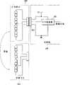
一个使用计算机的网络的结构的例子是如图1所示的层次型星型拓扑结构(连接结构)。为了构成层次型星型拓扑结构(连接结构),每一连线101均被连接在主机系统102(以后称PC102)和网络集线器103之间,PC102和节点104之间,或网络集线器103和节点104之间。在这种情况下,PC102被用于控制网络,并且网络只包括一个PC。具有信号的中继功能的网络集线器103提供了其它节点104或网络集线器103的连接点并且是用于建立网络的独立部件。每一节点104均是一个计算机I/O设备,例如是一个打印机106,一个扫描仪107,或是一个键盘(图中未显示)。An example of the structure of a network using computers is a hierarchical star topology (connection structure) as shown in FIG. 1 . In order to form a hierarchical star topology (connection structure), each
为了实现即插即用功能(以后简写为PnP功能),即在该功能中主机系统识别连接到上述网络的设备,寻找一适用于控制该设备的驱动程序,并且在适当定时安装它。存在一种传统的方法,用于根据预定协议读取有关与网络相连的设备(节点104)的信息。这一信息的特例包括模型的名称,厂商名称,功耗,最大数据速率及其它。In order to realize the plug-and-play function (hereinafter abbreviated as PnP function), that is, the function in which the host system recognizes the device connected to the above-mentioned network, finds a driver suitable for controlling the device, and installs it at an appropriate timing. There is a conventional method for reading information about a device (node 104) connected to the network according to a predetermined protocol. Specific examples of this information include model name, manufacturer name, power consumption, maximum data rate, and others.
为了由具有有限程序能力的OS实现PnP功能,存在一种方法,用于根据有关该设备(节点104)的信息把设备适当地分类(分成打印机类,输入类,显示类,图象类,声音类等),并且由一个相应类的标准驱动程序来驱动每个设备。例如,包括IEEEE1394及USB的标准是已知的实现上述PnP功能的网络标准。In order to implement the PnP function by an OS having limited program capabilities, there is a method for appropriately classifying (dividing into printer class, input class, display class, image class, sound class) a device based on information about the device (node 104) class, etc.), and each device is driven by a standard driver of the corresponding class. For example, standards including IEEE1394 and USB are known network standards for realizing the above-mentioned PnP function.
近些年,具有多功能(不同类)的组合装置的需求在不断增长,如具有打印机及扫描仪功能的组合装置。但是由于上述用于实现PnP功能的方法只适合于读取有关一种设备的识别的信息,因此上述方法并不适合于作为不同类的设备的组合的组合装置。由于该方法只适用于单功能设备,因此当通过一网络接口连接组合装置时就会出现以下问题。In recent years, there has been an increasing demand for combined devices with multiple functions (different types), such as combined devices with printer and scanner functions. However, since the above-mentioned method for realizing the PnP function is only suitable for reading information about the identification of one type of device, the above-mentioned method is not suitable for a combined device that is a combination of different types of devices. Since this method is only applicable to single-function devices, the following problems arise when connecting composite devices through a network interface.
多个具有单一功能的设备不允许被分配给一个网络设备。即,PC不允许多个驱动程序被安装到一个网络设备上。Multiple devices with a single function are not allowed to be assigned to a network device. That is, the PC does not allow multiple drivers to be installed on one network device.
由于组合装置不符合类的标准概念,因此其设备不能被标准驱动程序驱动。Since a composite device does not conform to the standard concept of a class, its devices cannot be driven by standard drivers.
要求为这些设备准备一个特定的驱动程序。因此需要通过把所使用的各驱动程序组合起来提供一个新的驱动程序。A specific driver is required for these devices. It is therefore necessary to provide a new driver by combining the used drivers.
由于多个不同的驱动程序例如不同概念的驱动程序如打印机的和扫描仪的驱动程序,被组合成一个,因此结果程序必定比单一功能的驱动程序大的多。Since multiple different drivers such as drivers of different concepts such as printer's and scanner's drivers are combined into one, the resulting program must be much larger than a single-function driver.
当一个驱动程序适合于两个功能,例如打印机功能和扫描仪功能时,则将会消耗更多不必要的系统资源。简而言之,所消耗的系统资源为单一功能设备所消耗的两倍。因此易得出结论,该方法不能完全体现PnP的特点。When one driver is suitable for two functions, such as a printer function and a scanner function, more system resources will be consumed unnecessarily. In short, it consumes twice as many system resources as a single-function device. Therefore, it is easy to conclude that this method cannot fully reflect the characteristics of PnP.
本发明的实现考虑到了上述的一般事例,本发明的一个目的就是提供一个具有良好操作性,即根据其可用功能可自动地被识别的组合装置,该组合装置的控制方法,和与之相关的网络系统。The realization of the present invention has taken into account the above-mentioned general case, and an object of the present invention is to provide a combination device with good operability, that is, automatically identifiable according to its available functions, a control method of the combination device, and related Network Systems.
本发明的另一目的是提供一遵守分类并且可由与各个类相对应的标准驱动程序驱动而无需特定驱动程序的组合装置,该组合装置的控制方法,和与之相关的网络系统。Another object of the present invention is to provide a composite device which complies with classification and can be driven by a standard driver corresponding to each class without requiring a specific driver, a control method of the composite device, and a network system related thereto.
本发明的另一目的是提供一组合装置,该组合装置的控制方法,和与之相关的网络系统,该组合装置适合于当该装置由一种功能切换到另一种功能时,用户不需为使主计算机识别这一切换而做特定的操作。Another object of the present invention is to provide a combination device, the control method of the combination device, and the network system related thereto. Specific operations are performed in order for the host computer to recognize this switch.
本发明的另一目的是提供一组合装置,该组合装置的控制方法,和与之相关的网络系统,该组合装置能够执行组合装置的功能切换而不影响与网络相连的其它设备。Another object of the present invention is to provide a combination device, a control method of the combination device, and a related network system, the combination device can perform function switching of the combination device without affecting other devices connected to the network.
本发明的另一目的是提供一组合装置,该组合装置能够响应来自主计算机要求组合装置切换功能的请求,使得主计算机识别该功能切换,该组合装置的功能切换可被执行而不需修改主计算机侧软件或硬件,该组合装置的控制方法,和与之相关的网络系统。Another object of the present invention is to provide a combined device capable of responding to a request from a host computer to switch functions of the combined device so that the host computer recognizes the function switch, and the function switch of the combined device can be performed without modifying the host computer. The computer side software or hardware, the control method of the combination device, and the related network system.
为实现上述目的,本发明的网络系统为一个包括一个主设备和一个能够进行功能切换的组合装置,所述组合装置被连接到所述主设备上。To achieve the above object, the network system of the present invention is a combination device including a master device and a function switchable device, and the combination device is connected to the master device.
其中所述组合装置包括用于识别功能切换的识别装置,和控制装置,用于当功能切换被所述识别装置识别时,执行控制以使得主设备识别该组合装置的功能。Wherein the combination device includes identification means for identifying function switching, and control means for performing control so that the host device recognizes the function of the combination device when the function switching is recognized by the identification means.
本发明的组合装置能够进行功能上的切换,所述组合装置被连接到一个主设备上。The combination device of the present invention is capable of functional switching, said combination device being connected to a master device.
所述组合装置包括识别装置,用于识别功能的切换,和控制装置,用于当功能切换被所述识别装置识别时,执行控制以使得主设备识别该组合装置的功能。The combination device includes recognition means for recognizing switching of the function, and control means for performing control such that the host device recognizes the function of the combination device when the function switching is recognized by the recognition means.
本发明的组合装置的控制方法为能够进行功能上的切换的组合装置的控制方法,所述组合装置被连接到一个主设备上。The control method of a combination device of the present invention is a control method of a combination device capable of switching functions, and the combination device is connected to one master device.
所述控制方法包括:The control methods include:
一个识别功能切换的识别步骤;和an identification step identifying the function toggle; and
一个当功能切换被所述识别步骤识别时,执行控制以使得主设备识别该组合装置的功能的控制步骤。A control step of performing control such that the host device recognizes the function of the combination device when function switching is recognized by the recognition step.
本发明的存储介质用于存储能够进行功能切换的组合装置的控制程序,所述组合装置被连接到一个主设备上。The storage medium of the present invention is used to store a control program of a combination device capable of switching functions, and the combination device is connected to a master device.
所述用于存储程序的存储介质包括:The storage medium for storing programs includes:
一个用于识别功能切换的识别步骤;和an identification step for identifying function toggles; and
一个当功能切换被所述识别步骤识别时,执行控制以使得主设备识别该组合装置的功能的控制步骤。A control step of performing control such that the host device recognizes the function of the combination device when function switching is recognized by the recognition step.
图1为表示一层次型星型网络的方法框图Figure 1 is a method block diagram representing a hierarchical star network
图2为打印机——扫描仪组合装置100中的网络控制系统的框图;2 is a block diagram of a network control system in the printer-
图3为头检测器209和头的框图;FIG. 3 is a block diagram of a
图4为表示构成网络的信号线和驱动程序的框图;Fig. 4 is a block diagram representing signal lines and drivers constituting the network;
图5A,5B和5C为表示电缆401连接定时和断开连接定时及信号线中的电压变化的框图;5A, 5B and 5C are block diagrams showing the connection timing and disconnection timing of the
图6为一打印机——扫描仪组合装置中头的替换的控制流程图;Fig. 6 is a control flowchart of the replacement of the head in a printer-scanner combination device;
图7为一打印机——扫描仪组合装置中重置的控制流程图;Fig. 7 is a control flowchart of resetting in a printer-scanner combination device;
图8为PC102的机制框图;Fig. 8 is the mechanism block diagram of PC102;
图9为由PC102执行的有关网络上的设备识别的流程图;FIG. 9 is a flow chart of device identification on the network performed by PC 102;
图10为表示第二实施例中的重置的控制流程图;FIG. 10 is a control flowchart showing reset in the second embodiment;
图11为表示第三实施例的打印机——扫描仪组合装置中头的替换的控制流程图;及Fig. 11 is a control flowchart showing head replacement in the printer-scanner combination device of the third embodiment; and
图12为一打印机——扫描仪的内部结构的透视图。Fig. 12 is a perspective view of the internal structure of a printer-scanner.
图12为表示一个作为本发明的一个实施例的打印机——扫描仪组合装置100的内部结构的透视图,该组合装置有打印机和扫描仪功能,这些功能可通过由一个头替换另一个头而有选择地使用。该图表示了一个打印机头被安置在其中的结构。图中,引线螺丝5005通过驱动力传送齿轮5011,5009而旋转,其中5011及5009与驱动电机5013的正向和反向旋转相连;并且,基座HC有一插头(图中未显示出)与引线螺丝5005的旋转槽5004相接合,且基座HC沿着导轨5003以箭头a,b的方向前后移动;当用作打印机时,则用于喷射墨滴的墨盒IJC被安置在基座HC上;当用作扫描仪时,则具有光传感器或具有类似的用于光电转换的组件的扫描仪头(图中未显示出)被安置在基座HC上。图象的记录或原件的扫描随着具有上述任一头的基座的转换运动而进行。片状压力板5002使得打印纸或读取原件在基座HC的运动方向上始终压着压纸卷筒5000。一个光耦合器5007,5008被提供,用于检查该区域中基座的操纵杆5006的出现,从而检测因电机5013的旋转方向的改变或因其它原因的原位。支撑组件5016支持覆盖组件5022,用于当装置被用作打印机时覆盖打印机头IJH的前端。吸引组件5015通过覆盖组件5022的孔眼吸引覆盖组件5022的内部,从而影响记录头的吸引恢复。清洁片5017被支持,使得它可通过支持组件5019而可前后移动,它们由主支撑板5018所支持。Fig. 12 is a perspective view showing an internal structure of a printer-
图2为一框图,表示作为本发明的实施例的打印机——扫描仪组合装置的网络控制系统。Fig. 2 is a block diagram showing a network control system of a printer-scanner combination device as an embodiment of the present invention.
打印机——扫描仪组合装置100有一个用于执行打印机的主控制的打印机控制电路201,一个用于打印的打印机头或用于图象读取的扫描仪头210,一个用于检测头类型的头检测器209,一个用于控制打印机的基本输入/输出系统(BIOS)206,BIOS作为执行打印机主控制的控制程序存储在ROM或其它存储介质中,一个作为网络接口的收发器部件203,收发器部件203用于连接到主计算机或网络集线器上,和一个用于控制收发器部件203的计时器204。收发器部件203包括一个作为其主要部分的收发器208,一个以后会详细描述的R控制器205,和一个电阻器R。The printer-
打印机控制电路201根据通过收发器部件203来自网络信号线202的控制,执行打印控制或读取扫描仪数据的控制。打印机控制电路201通过控制计时器204而控制收发器部件203内的R控制器205,从而控制与R控制器205相连的电阻器R,其中R控制器205主要包括FET(图中未显示出来)。The
用于打印机控制的BIOS206包括控制程序,打印字体(CG),和其它固定数据,并且执行用于电机控制,打印机头和扫描仪头的驱动控制等的控制程序。根据打印机控制BIOS206,打印机控制电路201接收来自信号线202的打印命令,数据,或扫描命令,或者输出扫描数据。存储器207有一个用作寄存器的工作域,这些工作域可作为用于存储一行打印数据的行缓冲区,用于存储重新转换成点的点转换缓冲区,和用于存储来自网络的数据的发送/接收缓冲区。The
头检测器209用于检测安置在基座上的头210。头210在打印机控制电路201的控制下把图象记录在打印纸上或扫描原件。当打印机的打印头被安置在基座上时,则头210进行打印,当扫描仪头被安置在基座上时,则读取数据。The
计时器204有一个计数器,并执行控制以在接收一来自打印机控制电路201的脉冲信号后,使R控制器205保持一段固定时间的空闲状态。The
当头被另一头替换时,尤其是当打印机头被扫描仪头替换时,打印机控制电路201向计时器204发送一脉冲。接收到该脉冲后,计时器204执行控制以使R控制器205保持一段固定时间的空闲状态。而且,响应来自网络的请求,打印机控制电路201根据头检测器209的检测结果发送包括扫描仪的模型名,其厂商名,其最大数据速率等信息,这些信息存储在打印机控制BIOS206中。The
另一方面,当扫描仪头被一打印机头所替换时,则执行类似的操作,响应来自网络的要求读取信息的请求,打印机控制电路201发送包括打印机的模型名,其厂商名,其功耗,其最大数据速率等信息,这些信息存储在打印机控制BIOS206中。On the other hand, when the scanner head is replaced by a printer head, similar operations are performed. In response to a request from the network to read information, the
图3是头检测器209和头中的检测电路的结构图。FIG. 3 is a block diagram of the
头检测器209主要包括AD转换器301。每个打印机头302(尤其是,盒式喷墨头)和扫描仪头303(尤其是,CCD夹头)均包括用于识别的电阻器。而且,每一头均通过连接器304接收同样的电源Vp供给和电阻器的分压信号。The
根据上述结构,AD转换器301根据头内电阻器的分配比例把分压信号转换成数字数据。对于每一类头这一分配比例是固有的,并且分压也是根据这一比例决定的。因此,打印机控制电路201可通过读取分压数据而判定安置在头安装部分或基座上的头的类型。图3中,打印机头302的分配比例是1∶1,而扫描仪头303的分配比例是3∶1。AD转换器的输出值也是根据该比例决定的,因此也可用于判定头类型。According to the above structure, the
图4为一个表示本发明的一个实施例中用于构成网络的信号线及其驱动程序的框图。Fig. 4 is a block diagram showing signal lines and their drivers for constituting a network in one embodiment of the present invention.
包括信号线data1和data2的屏蔽双扭线电缆401(以后称为电缆401)把PC102的收发器部件402同装置100的收发器部件203连接了起来。每一信号线均把收发器208和208’连接起来(类似于收发器208)以取得在电子基础上的数据交换。每一电阻器R1,R2均与相关的信号线相连以防止信号线有高阻抗。图4表示了一个PC直接连接到设备的例子,但是也适用于前面所述的网络集线器103被置于它们之间的情况。A shielded twisted pair cable 401 (hereinafter referred to as cable 401 ) including signal lines data1 and data2 connects the
包括多个上行端口和一个下行端口的网络集线器103具有向端口中继数据的功能,及把连接到一上行端口(连接或断开连接)的信号的改变传送到下行端口的功能。The
每个收发器208,208’均包括了不同放大类型的输入/输出设备,用于读取各自信号线的电压的端口,串——并转换器等,并且控制信号线data1和data2的电信号。每一信号线data1和data2均可根据预定协议串行地传送PC402的控制信号和来自其它节点的信号。Each
下面所描述的是根据USB串行传送的信号的状态:Described below is the state of the signal according to the USB serial transfer:
一个位时间单位是82ns;A bit time unit is 82ns;
J(空闲状态)状态由data1的高电平和data2的低电平状态决定;The state of J (idle state) is determined by the high level of data1 and the low level state of data2;
K状态由data1的低电平和data2的高电平状态决定;The K state is determined by the low level of data1 and the high level state of data2;
断开连接状态由data1为低电平状态且data2为低电平状态已被检测了2.5ns或更长时间这一条件来决定;The disconnected state is determined by the condition that data1 is low and data2 has been detected for 2.5 ns or longer;
报文结束由data1为低电平状态且data2为低电平状态已持续了26个位时间单位且以后将检测到一个位时间单位的J状态的条件来决定;The end of the message is determined by the condition that data1 is in a low level state and data2 has been in a low level state for 26 bit time units, and a J state of one bit time unit will be detected later;
由空闲状态到K状态的转换表示报文的开始;The transition from the idle state to the K state indicates the beginning of the message;
从报文结束开始不少于16个位时间单位的时间流逝表示超时。The lapse of time not less than 16 bit time units from the end of the message indicates a timeout.
本实施例中,用于在设备间进行同步的时钟信号和用于指示设备的地址在报文开始时被加到报头。因此,具有图1所示的拓扑结构的网络也可在逻辑基础上在PC102的核心外包括一个星型网络。串行数据由一个位时间单位的J(逻辑高电平)或K(逻辑低电平)状态表示。报文总是由PC102生成,并且根据报文中的命令由指定的设备接收数据。而且数据的交换在二者之间进行。In this embodiment, a clock signal for synchronization between devices and an address for indicating a device are added to the header at the beginning of the message. Therefore, a network having the topology shown in FIG. 1 could also logically include a star network outside the core of
当data1和data2的信号在PC402端被检查到时,data1的高电平状态和data2的低电平状态表示网络的节点端的终端的设备的连接。断开连接状态在无信号交换的状态时决定,也即data1低电平和data2低电平的状态已被检查了2.5us或更长时间时的状态。When the signals of data1 and data2 are detected at the PC402 end, the high level state of data1 and the low level state of data2 indicate the connection of the terminal equipment at the node end of the network. The disconnected state is determined in the state of no handshake, that is, the state when the state of data1 low level and data2 low level has been checked for 2.5us or more.
在设备端的收发器部件203中,data1通过电阻器R3与R控制器205相连。与电阻器R3相连的R控制器205根据主要包括FET的头检测器209的检测结果而被控制,并且可建立设备100的断开连接的虚状态。In the
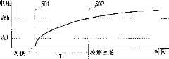
图5A到5C表示设备100的连接时间和断开连接时间及其data1的电压变化。5A to 5C show the connection time and disconnection time of the
与data2相连的收发器208的端口处于非有效状态,并因此被电阻器R2保持在低电平状态。The port of
图5A到5C中的Vol和Voh相应地表示与PC 102的data1相连的端口的可检测的“低”电压和“高”电压。Vol and Voh in FIGS. 5A to 5C denote detectable "low" voltage and "high" voltage of the port connected to data1 of
图5A表示设备的正常连接顺序。Figure 5A shows the normal connection sequence of devices.
时间点501是设备被连接到网络的定时。此时,与电阻器R3相连的R控制器205输出5V,并且data1的电压随着电阻R3和电缆401的电容而增加。在一定时间T1过后(或在时间点502),data1的电压超过了Voh,使得可认为端口输入处于高电平状态。因此,PC102可发现设备被连接到上行端口。PC102可根据预定协议指定最近被加到电缆401的设备并把相应于该设备的驱动程序放入存储器中。A point of
图5B表示设备的正常断开连接顺序。Figure 5B shows the normal disconnection sequence of a device.
时间点503是设备100从网络上被分离的定时。data1的电压随着电阻R1和data1的线路电容而减少。在一定时间T2后(或在时间点504),data1的电压低于Vol,使得可认为端口输入处于低电平状态。因此,PC102可发现在2.5us后设备被断开连接。电缆401和设备100的分离使得PC102取消用于已被断开连接的设备100的驱动程序,并重新安排系统内部。A time point 503 is the timing when the
图5C表示当前实施例中,在R控制器205的控制下设备与网络相连及从网络上断开连接的虚操作的电压波形图。FIG. 5C shows a voltage waveform diagram of virtual operation of devices connected to and disconnected from the network under the control of the
在时间点505,在R控制器205的控制下停止给电阻器R3供电。这表明电缆401被分离出来时波形保持不变。能量提供的停止使得data1的电压随着电阻R1和电缆的电容而不断减少。在一定时间T2后(或在时间点506),data1的电压低于Vol,使得端口输入可被认为处于低电平状态。At
而且,在一定时间T3(>2.5us)后,R控制器205再次开始对于电阻器R3的能量供应。因此,PC102认为设备好象被断开连接了,正如上行端口的电缆401的设备被物理的分离一样。时间T3中PC102可删除设备(打印机驱动程序或扫描仪驱动程序)的驱动程序并重置系统内部。当对于电阻器R3的能量供应重新开始时,则波形与设备被加到电缆401上时是一样的,并且data1的电压随着电阻R3和电缆的电容而增加。在一定时间T1过后(或在时间点508),data1的电压超过了Voh,使得端口输入可被认为处于高电平状态。因此,PC102可发现设备被连接到一个上行端口。然后,PC102可从设备读取信息并根据所读信息安装适当的驱动程序(扫描仪驱动程序或打印机驱动程序)。Moreover, after a certain time T3 (>2.5us), the
图6为本发明的打印机——扫描仪组合装置中执行头的替换的控制流程图。该程序由打印机控制电路201执行。FIG. 6 is a flow chart of control for performing head replacement in the combined printer-scanner device of the present invention. This program is executed by the
通过读头检测器209,步骤601判定用户是否以一个头替换另一个头。当存在一被执行的替换操作时,则步骤602判定新安置的头是否与此替换操作前所安置的头类型相同。当判定头类型同操作前的头相同时,流程转向步骤601。另一方面,当判定头为新类型时,则流程转到步骤603。Through the read
步骤603设置替换标志以表示用另一个不同类型的头替换当前头,然后流程转向步骤604。步骤604把用于端口的重新连接的脉冲信号应用于计时器204,然后该处理过程结束。Step 603 sets the replacement flag to indicate that the current header is replaced with another header of a different type, and then the process goes to step 604 . Step 604 applies a pulse signal for port reconnection to
当计时器204被脉冲信号触发时,计时器204控制R控制器205以停止对于电阻器R3的能量供应。当计时图5C所示的T2+T3时间后,计时器重新开始能量供应。结果是,虽然电缆仍旧与网络相连,但是PC102认为设备的连接和断开连接操作之间好象有一T1+T3的时间间隔。设备100的断开连接和连接过程以这种方式执行。When the
随着设备100的分离,PC102从PC102上卸载设备100的驱动程序。结果,PC102认为设备好象是最近被连接到网络的。因此,PC102发送一重置信号给新设备100,并根据预定协议开始包括有读信息的过程的处理。With the detachment of the
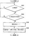
图7是当来自PC的重置信号被接收到时的控制流图。这一过程在图6的步骤604中的网络的断开连接/连接时,当设备100接收到发自PC102的重置命令时开始。Fig. 7 is a control flow diagram when a reset signal from the PC is received. This process starts when the
首先,执行步骤701以检测判定标志,从而判定重置是由于设备的加电还是由于头的替换。在头替换的情况下,在步骤603中替换标志被置为1。因此,当替换标志=0时,也就是当判定重置是加电重置时,则流程转到步骤702;然而,当替换标志=1时,也就是当判定重置是由于头替换时,则流程转到步骤703。First, step 701 is executed to detect the determination flag, so as to determine whether the reset is due to power-on of the device or replacement of the head. In the case of header replacement, the replacement flag is set to 1 in step 603 . Therefore, when the replacement flag=0, that is, when it is judged that the reset is a power-on reset, the flow goes to step 702; however, when the replacement flag=1, that is, when it is judged that the reset is due to head replacement, Then the flow goes to step 703 .
步骤702执行存储器,打印机机制等的初始化操作,并且由于存储器已被初始化了,因此步骤703只执行打印机机制的初始化操作。这时,替换标志被重置为0。Step 702 performs initialization operations of the memory, printer mechanism, etc., and since the memory has already been initialized, step 703 only performs initialization operations of the printer mechanism. At this time, the replacement flag is reset to 0.
接下来,步骤704从头检测器209读取数字信号以判定头的状态。依据这些状态,步骤705和706各自执行有关打印机头和扫描仪头的操作。当读取头检测器209后判定头为扫描仪头303时,设备准备一打印机控制BIOS 206的引线地址,该地址中存储了表1所示的为扫描仪所准备的信息。当判定头为打印机头302时,则设备准备一地址,该地址中存储了为打印机(参看表1)所准备的信息。Next, step 704 reads the digital signal from the
步骤707根据前面所准备的地址从打印机控制BIOS206中读取定长数据,预先地把数据转换成存储器207中的点信息,并准备响应来自PC102的要求读信息的请求。当在步骤708中设备接收到来自PC102的要求读取设备信息的请求时,则执行步骤709,通过收发器部件203把存储器207中的扩展信息传送到PC102,然后该处理过程结束。Step 707 reads the fixed-length data from the
由于以这种方式可根据头的状态正确地把信息传送给PC102,因此,传送信息能够在适当的时间实现PnP功能。Since the information can be correctly transferred to the
下面的表1为一个设备信息从作为本实施例的扫描仪——打印机组合装置发送到作为主计算机的PC的例子。Table 1 below is an example in which device information is sent from the scanner-printer combination apparatus as the present embodiment to the PC as the host computer.
(表1:设备信息的例子)
当所安装的是打印机头时,则“厂商名(Canoe)”,“产品ID(01h)”,“类(打印机)”,及“传送大小(8字节)”被发送给PC。当所安装的是扫描仪头时,则“厂商名(Canoe)”,“产品ID(02h)”,“类(图象)”,及“传送大小(32字节)”被发送给PC。When a printer head is installed, "Vendor Name (Canoe)", "Product ID (01h)", "Class (Printer)", and "Transfer Size (8 bytes)" are sent to the PC. When a scanner head is installed, "manufacturer name (Canoe)", "product ID (02h)", "class (image)", and "transfer size (32 bytes)" are sent to the PC.
图8为PC102的机制框图。FIG. 8 is a mechanism block diagram of PC102.
在PC102中,一个用于实现主要控制的中央处理器(CPU)801通过不同的路径(数据路径,地址总线控制路径)与不同的框相连。In the
PC102具有一个实现其主要控制的CPU801和一个用于存储基本控制程序的只读存储器(BIOSROM)802。应用程序从外部存储器803(尤其是,软盘,硬盘,或其它)中读出,并且通过使用系统存储器804执行程序。这时,屏幕的显示方法是通过使用显示控制器805并允许从键盘(KB)807输入,从而在显示器806(尤其是,液晶显示屏或CRT)上显示字符等。网络I/F809执行对于来自或发送到网络线上的信号的输入/输出控制,并且网络I/F809包括前面所提到的收发器部件402。The
图9为PC102的有关网络的操作流程图。FIG. 9 is a flowchart of the operation of the
步骤901中,CPU801总是监测网络I/F809的信号的变化并判定是一新设备被加到网络上还是一设备从网络上分离了出来。对于每一设备均进行以下方式的判定,即如果在非通信期间其电缆的电位不超过图5A到5C中所示的Vol,则判定设备被断开连接;如果其电缆的电位不小于Voh,则判定设备被连接。当一新设备被判定为被连接(附加)时,则流程转向步骤903;当设备为被断开连接(或被分离)时,则流程转向步骤902。步骤902清除用于被断开连接的设备的驱动程序,其中该驱动程序已在存储器中得到扩展,释放其所占用的空间以备其它软件使用,并结束这一处理过程。In step 901,
步骤903把用于初始化的重置信号发送给被连接的新设备并转向步骤904。接收到重置信号的设备根据图7中的程序发送设备信息,以响应来自PC的请求。Step 903 sends a reset signal for initialization to the connected new device and turns to step 904 . The device that received the reset signal sends device information according to the procedure in Figure 7 in response to the request from the PC.
步骤904把要求设备信息的请求发送给被连接的新设备并读取这些数据。步骤905检查所读取的设备信息,尤其是厂商,类,传送大小等,并判定设备是否已被注册或驱动程序是否已加载到外部存储器803中。如果已注册,则流程转向步骤906;如果未注册,则流程转向步骤907。Step 904 sends a request for device information to the new connected device and reads the data. Step 905 checks the read device information, especially the manufacturer, class, transfer size, etc., and determines whether the device has been registered or whether the driver has been loaded into the
步骤907给予用户提示,提示用户需安装该设备的一个新驱动程序,然后流程转向步骤908。步骤908安装这一新驱动程序,其中这一新驱动程序从可删除存储器例如FD中,或通过通信在由存储器和HDD所表示的外部存储器中获得,把驱动程序设置为注册状态,然后该处理过程结束。Step 907 prompts the user to install a new driver for the device, and then the process turns to step 908 . Step 908 installs this new driver, wherein this new driver is obtained from removable storage such as FD, or in external storage represented by storage and HDD through communication, sets the driver to a registered state, and then the process The process is over.
另一方面,步骤906参考在步骤904中所读取的设备信息,选择存储在由HDD表示的外部存储器803中并已注册的驱动程序;步骤909把驱动程序转换成存储器中的点信息;然后该处理过程结束。On the other hand, step 906 refers to the device information read in step 904, selects the driver program stored in the
现在,让我们来解释一下网络集线器103被插入在PC102和设备100间的操作。Now, let us explain the operation in which the
网络集线器103执行监测操作,该操作类似于前面所描述的PC102的端口监测操作。当在上行端口所监测到的变化是信号(连接或断开连接)时,则网络集线器103把信号转换成表示状态变化和网络集线器的状态的数据,使得PC102可读取转换后的数据。每隔一段时间(每10ms),PC102读取每个与之相连的网络集线器103的状态变化。另一方面,只有有状态变化的网络集线器103把表示状态变化的数据发送给PC102。当PC102通过读取表示网络集线器103的状态变化的数据监测到这一状态变化时,PC102可通过从有相应变化的网络集线器103中读取表示状态的转换后的数据,识别连接状态或断开连接状态。为了监测设备的断开连接状态,PC102执行前面所述的步骤902。另一方面,为了监测设备的连接状态,PC102控制网络集线器以把用于初始化的重置信号发送给被连接的设备并执行步骤904。因此,即使网络中由网络集线器103也不会出现问题。The
表示信号(连接或断开连接)变化的信息从设备100流向下行侧(PC102)。而且,根据连接信息的设置(信息)是从PC102到设备的。因此,可实现状态的改变而不会影响其它同网络相连的设备及至PC102的中途下行设备。Information representing a change in a signal (connection or disconnection) flows from the
如上所述,当前实施例的打印机——扫描仪组合装置建立在这样一种结构中,该结构中随着从打印机头到扫描仪头的替换或从扫描仪头到打印机头的替换,头的类型被判定,并且根据头的类型,与主计算机相连的信号线的电力被停止供应一段固定的时间,然后继续提供,从而使得主计算机可识别设备的连接和断开连接操作。这一结构使得设备响应来自PC的请求从而输出设备的不同信息(模型名,ID,类等),这些信息对于实现PnP是必需的,或对于主计算机在信号线连接的情况下根据头的类型而实现自动地识别设备是必需的。As described above, the printer-scanner combination device of the present embodiment is built in a structure in which the The type is determined, and according to the type of head, the power supply of the signal line connected to the host computer is stopped for a fixed period of time and then continued so that the host computer can recognize the connection and disconnection operations of the device. This structure makes the device respond to the request from the PC to output different information of the device (model name, ID, class, etc.), which is necessary to realize PnP, or to the host computer according to the type of header in the case of signal line connection It is necessary to realize automatic identification of equipment.
在这样构造的组合装置中,根据所使用的功能来识别每个设备,而不需为组合装置准备特定的驱动程序,甚至可以使用与各个类相应的标准驱动程序。In the composite device thus constructed, each device is identified according to the function used without preparing a specific driver for the composite device, and even a standard driver corresponding to each class can be used.
另外,具有信号线的设备可选择地使用这两种功能。In addition, devices with signal lines can selectively use both functions.
由于只有头的切换才会使得主计算机识别它,因此用户不需要对主计算机执行任何特定的操作,这就体现了良好的可操作性。Since the main computer recognizes it only by switching the head, the user does not need to perform any specific operation on the main computer, which reflects good operability.
在系统的一个例子中,扫描仪设备与打印机设备相连以作为一复印机,装置可被安排成使得主计算机能够识别装置的变化,这一识别过程是通过监测从只是打印机的状态到扫描仪与打印机相连的状态的变化(或与之相反的变化)并改变前面所述的信号线的电压来实现得,并且主计算机的驱动程序随之切换。In one example of a system where a scanner device is connected to a printer device to act as a copier, the device can be arranged so that the host computer can recognize a change in the device by monitoring the state of the printer from the scanner to the printer. The change of the state of the connection (or the opposite change) is realized by changing the voltage of the signal line mentioned above, and the driver program of the host computer is switched accordingly.
在打印机配备有诸如双面打印单元,分类单元,订书单元这些选项时,装置可安排成使得主计算机可象前面所描述的一样通过改变信号线的电压来识别装置的状态的变化。当装置的程序或其它部分升级时,装置也可安排成使得主计算机可象前面所描述的那样通过改变信号线的电压来识别装置的状态的变化。When the printer is equipped with options such as a duplex unit, a sorting unit, and a stapler unit, the device can be arranged so that the host computer can recognize a change in the state of the device by changing the voltage of the signal line as previously described. When the program or other parts of the device are upgraded, the device can also be arranged so that the host computer can recognize the change of state of the device by changing the voltage of the signal line as described above.
当前实施例被描述成一个星型网络,但它也可在包括对等网络的网络中实施。当前实施例被描述成具有扫描仪和打印机的装置,但是在所加载的设备类型上并没有特定的限制。在以后修正的例子中,组合装置也可使用三个或更多的设备。用于监测设备的连接和断开连接的装置被描述成一种使用网络信号的电压的装置,但也可采取其它的装置来实现,尤其是,通过一个通信无效状态来监测,通过监视计时器来监测等,而且也可考虑使用其它的不同的装置。The current embodiment is described as a star network, but it can also be implemented in networks including peer-to-peer networks. The current embodiment is described as an apparatus having a scanner and a printer, but there is no particular limitation on the types of devices loaded. In later modified examples, three or more devices may also be used in combination. The means for monitoring the connection and disconnection of equipment is described as a means using the voltage of the network signal, but other means can be used, in particular, monitoring by a communication invalid state, monitoring by a watchdog timer monitoring, etc., and other different devices can also be considered.
而且,当前实施例被安排成在头替换后识别头的类型,并随后执行设备的自动识别,但是只要当信息是表示组合装置的功能间的切换时,本发明就不仅限于这一种结构。例如,可以在由用户操作的开关进行切换。在这种情况下,每个功能所固有的信号被监测,随后功能的切换被识别。Also, the present embodiment is arranged to recognize the type of the head after head replacement, and then perform automatic recognition of the device, but the present invention is not limited to this structure as long as the information is indicative of switching between functions of the combined device. For example, switching may be performed at a switch operated by the user. In this case, the signals inherent to each function are monitored and subsequent switching of functions is recognized.
第二实施例second embodiment
第二实施例基本上与第一实施例的结构是一样的,但是第二实施例被提供以三种类型的头,包括一个新加进去的高清晰打印头。该高清晰打印头包括前面所述的电阻器并且其电阻器的分配位置也与其它的头不同。因此,头检测器209可读取与其它两个头不同的数据并且打印机控制电路201可监测每个头的类型。The second embodiment is basically the same structure as the first embodiment, but the second embodiment is provided with three types of heads including a newly added high definition print head. This high-definition print head includes the aforementioned resistors and its distribution position of the resistors is also different from other heads. Therefore, the
图10为表示第二实施例的重置的控制流程图。Fig. 10 is a control flowchart showing resetting of the second embodiment.
当在图6的步骤604中设备100被从网络上断开连接或被连接到网络上时,则在图9的步骤903中PC102发送重置命令。接收到该重置命令后,打印机在步骤701判定这一重置是加电重置还是由于头替换的重置。当判定为加电重置时,在流程转向步骤702;当判定为由于头替换的重置时,则流程转向步骤703。值得注意的是,与图7中相同的程序被标注了相同的参考标记。When the
步骤702执行存储器,打印机机制等的初始化操作,由于存储器已被初始化,因此步骤703只执行打印机机制的初始化操作。然后在步骤704中判定安装的是哪个头,并且相应类型的信息在步骤1001,1002或706中被准备好。尤其是,当头检测器209的读结果判定头为扫描仪头,则流程转向步骤706,以准备扫描仪的设备信息的地址。这一信息是存储在打印机控制BIOS206中的。当判定为标准打印头时,则流程转向步骤1001,如同在步骤706中一样,准备标准打印机的设备信息的地址。当判定为高清晰打印头时,则流程转向步骤1002,如同在步骤706中一样,准备高清晰打印机的设备信息的地址。Step 702 executes the initialization operation of the memory, the printer mechanism, etc. Since the memory has been initialized, step 703 only executes the initialization operation of the printer mechanism. It is then determined in step 704 which header is installed, and the corresponding type of information is prepared in step 1001, 1002 or 706. In particular, when the read result of the
步骤1003利用以上所设置的设备信息的地址,读取打印机控制BIOS206中的设备信息,并将其初步地转换成存储器207中的点阵信息,并准备响应来自PC102的请求。当在步骤708中接收到要求读的请求时,则流程转向步骤709,把转换到存储器207中的信息发送给收发器203,然后结束这一处理过程。相应地,根据头的状态,正确信息被发送给PC102以传送信息,从而在适当的时刻实现PnP功能。Step 1003 uses the address of the device information set above to read the device information in the printer control BIOS206, and convert it into dot matrix information in the
由于PC102识别出一个设备被断开连接,然后一个新设备被连接到网络上,如上所述,因此它也可为另一种类型的头(使用不同打印方法的头)安装不同的驱动程序,如同用于不同的设备如扫描仪的驱动程序。Since the
而且,模型名和ID主要被用作发送给PC102的信息,但是其它类型的信息也可类似地被改变。尤其是,也可能利用功耗信息,网络上的通信速率信息,和包括传送数据大小,信息量大小等的信息来改变PC102的处理。因此,对于通过网络发送的信息并无特定的限制。Also, the model name and ID are mainly used as information sent to the
第三实施例third embodiment
图11为表示第三实施例的打印机——扫描仪组合装置中头的替换的控制流程图。Fig. 11 is a control flowchart showing head replacement in the printer-scanner combination device of the third embodiment.
当头替换过程由运行在PC102上的应用程序触发时,在步骤1101中判定PC102是否发送了一个用于头替换的请求。当该请求被接收到时,为了实现头的替换执行步骤1102把打印机的头移动到预定位置。步骤1103一直等待,直到用户已经完成了头替换的操作。步骤1104在当一种新类型的头被识别时执行。在步骤1104中,替换标志表示头的替换已完成,端口时设置/重置,一个脉冲信号被应用于计时器204,一个用于控制设备的断开连接和重新连接的指令被提供给计时器204,然后该处理过程结束。When the header replacement process is triggered by an application running on the
一旦计时器204被脉冲信号触发,则计时器204保持一段预定的T2+T3时间,在该时间段中停止对于电阻器R3的电力供应,然后重新开始电力供应。相应地,一旦当电缆被保持同网络相连时,则PC102执行网络的断开连接和连接操作。Once the
PC102根据网络的断开连接,卸载已被加载到PC102中的驱动程序。由于PC102假定一新设备被连接到网络,因此它把重置信号发送给该新设备并根据预定协议执行操作。The
因此,用于设备的断开连接的请求可从PC102开始,并且连接到网络的新设备可在头的替换,断开连接,及重新连接后被识别。这就允许远程控制对于组合装置的功能间的切换的请求,并且响应该请求的设备识别操作可通过网络由PC102执行。Thus, a request for disconnection of a device can be initiated from the
第四实施例Fourth embodiment
前面所描述的实施例适用于从打印机控制电路201产生用于头替换或其它目的的脉冲,并使得计时器204接收该脉冲,执行控制,从而使得R控制器205在一段固定的时间段处于空闲状态,但是也可采用另一种可取得同样效果的方法,通过使用打印机控制BIOS206的一系列初始化序列自动地重置打印机控制设备并控制对于R3的电力供应。The previously described embodiment is adapted to generate a pulse from the
其它实施例other embodiments
本发明的目的也可由一实施例实现,该实施例中系统或装置被提供以存储介质,用于存储实现上述实施例的功能的软件的程序代码,且系统的计算机(或CPU或MPU)或装置读取存储在存储介质中的程序代码以执行程序。The purpose of the present invention can also be achieved by an embodiment, in which the system or device is provided with a storage medium for storing the program code of the software that realizes the functions of the above-mentioned embodiments, and the computer (or CPU or MPU) of the system or The device reads program codes stored in the storage medium to execute the program.
在这种情况下,从存储介质中读出的程序代码本身完成了上述实施例的功能,且存储程序代码的存储介质构成了本发明。In this case, the program code itself read out from the storage medium implements the functions of the above-described embodiments, and the storage medium storing the program code constitutes the present invention.
用于提供程序代码的存储介质的例子包括软盘,硬盘,光盘,磁光盘,CD-ROM,CD-R,磁带,非易失性存储器卡,ROM等。Examples of storage media for providing program codes include floppy disks, hard disks, optical disks, magneto-optical disks, CD-ROMs, CD-Rs, magnetic tapes, nonvolatile memory cards, ROMs, and the like.
本发明不仅涉及通过执行从计算机中读出的程序代码来实现上述实施例的功能的实施例,而且包括依据程序代码的指令,运行在计算机上的OS(操作系统)的指令来执行部分或整个实际处理的过程从而实现前面所述的功能的实施例。The present invention not only relates to an embodiment in which the functions of the above-described embodiments are realized by executing program codes read from a computer, but also includes instructions of an OS (operating system) running on a computer to execute part or the whole The process of actual processing thus realizes the embodiments of the aforementioned functions.
而且,本发明还涉及一实施例,在该实施例中,从存储介质中读取的程序代码被写入一存储器中,其中存储器位于计算机内的一个功能扩展板中或位于一个连接到计算机上的功能扩展部件中,然后根据程序代码的指令,CPU或功能控制板中所提供的其它部件或功能扩展部件执行部分或整个实际处理的过程,从而实现前面所述的功能。Moreover, the present invention also relates to an embodiment in which the program code read from the storage medium is written into a memory, wherein the memory is located in a function expansion board in the computer or in a computer connected to the computer. Then, according to the instructions of the program code, the CPU or other components or function expansion components provided in the function control board execute part or the entire actual processing process, so as to realize the aforementioned functions.
如上所述,根据本发明的组合装置,其控制方法,及与之相连的网络系统使得主计算机根据它所使用的功能识别组合装置为哪个设备。As described above, according to the present invention, the combined device, its control method, and the network system connected thereto allow the host computer to recognize which device the combined device is based on the functions it uses.
因此,组合装置被安排成能够自动识别目前可用功能,从而取得良好的可操作性。Therefore, the combined device is arranged to be able to automatically recognize the currently available functions, thereby achieving good operability.
本发明的组合装置十分适合于不需特定驱动程序的分类,甚至可由与相应类相称的标准驱动程序来驱动。The combination device of the present invention is well suited for classes that do not require specific drivers, and can even be driven by standard drivers commensurate with the corresponding class.
在组合装置的功能间进行切换时,用户不需执行使主计算机识别它的特定操作。When switching between the functions of the combination device, the user does not need to perform specific operations for the host computer to recognize it.
组合装置的功能间的切换操作可被执行,而不会影响连接到网络的其它设备。Switching operations between functions of the combination device can be performed without affecting other devices connected to the network.
为了响应要求在主计算机和组合装置的功能间进行切换的请求,组合装置使主计算机识别功能间的切换,使得可执行组合装置的功能间的切换,而不会改变主计算机端的软件或硬件。In response to a request to switch between functions of the host computer and combination device, the combination device causes the host computer to recognize the switch between functions so that switching between functions of the combination device can be performed without changing software or hardware on the host computer side.
Claims (40)
Applications Claiming Priority (6)
| Application Number | Priority Date | Filing Date | Title |
|---|---|---|---|
| JP264601/1997 | 1997-09-29 | ||
| JP26460197 | 1997-09-29 | ||
| JP264601/97 | 1997-09-29 | ||
| JP240252/1998 | 1998-08-26 | ||
| JP240252/98 | 1998-08-26 | ||
| JP24025298AJP4026948B2 (en) | 1997-09-29 | 1998-08-26 | Network system, device, device control method, and storage medium |
Publications (2)
| Publication Number | Publication Date |
|---|---|
| CN1215188Atrue CN1215188A (en) | 1999-04-28 |
| CN1133946C CN1133946C (en) | 2004-01-07 |
Family
ID=26534638
Family Applications (1)
| Application Number | Title | Priority Date | Filing Date |
|---|---|---|---|
| CNB981208487AExpired - Fee RelatedCN1133946C (en) | 1997-09-29 | 1998-09-29 | Device connected to main device via network and connection control method thereof |
Country Status (5)
| Country | Link |
|---|---|
| US (2) | US6557033B2 (en) |
| EP (1) | EP0905608B1 (en) |
| JP (1) | JP4026948B2 (en) |
| CN (1) | CN1133946C (en) |
| DE (1) | DE69824360D1 (en) |
Cited By (3)
| Publication number | Priority date | Publication date | Assignee | Title |
|---|---|---|---|---|
| CN1322419C (en)* | 2001-09-13 | 2007-06-20 | 鸿友科技股份有限公司 | Electronic system capable of downloading advertising materials |
| CN102111446A (en)* | 2011-01-12 | 2011-06-29 | 华为终端有限公司 | Device connection handling method, combination equipment and host equipment |
| CN106997301A (en)* | 2017-03-31 | 2017-08-01 | 广东欧珀移动通信有限公司 | A kind of method for upgrading software, device and electronic installation |
Families Citing this family (41)
| Publication number | Priority date | Publication date | Assignee | Title |
|---|---|---|---|---|
| JP4026948B2 (en)* | 1997-09-29 | 2007-12-26 | キヤノン株式会社 | Network system, device, device control method, and storage medium |
| US6950860B1 (en)* | 1999-07-02 | 2005-09-27 | Master Solutions, Inc. | Method and system for integrating building services by developing and loading an adapter element for each of the devices and applications of plurality of integrated building services to encapsulate the plurality of integrated building services with a standard interconnection behavior |
| JP4553279B2 (en)* | 2000-03-09 | 2010-09-29 | インターナショナル・ビジネス・マシーンズ・コーポレーション | Data transfer system, data transfer terminal, controller, and interface method |
| JP4290309B2 (en)* | 2000-03-13 | 2009-07-01 | シャープ株式会社 | Information communication apparatus, information communication method, and remote management system |
| JP2001290753A (en)* | 2000-04-06 | 2001-10-19 | Casio Comput Co Ltd | Electronics |
| US7269746B1 (en)* | 2000-11-27 | 2007-09-11 | Hewlett-Packard Development Company L.P. | Method of transmitting identification data from an option pack to a main unit before the option pack is fully powered |
| US6981033B2 (en)* | 2000-12-04 | 2005-12-27 | Hewlett-Packard Development Company, L.P. | Selection of a candidate peripheral device |
| JP2002175263A (en)* | 2000-12-05 | 2002-06-21 | Canon Inc | Electronic device, control method, and recording medium |
| JP3977059B2 (en) | 2000-12-22 | 2007-09-19 | キヤノン株式会社 | Information processing apparatus, method, and control program |
| US20020083430A1 (en)* | 2000-12-26 | 2002-06-27 | Tadao Kusuda | Uninstall control apparatus which controls uninstallation of device control software |
| JP3526565B2 (en)* | 2001-01-18 | 2004-05-17 | 松下電器産業株式会社 | Network equipment |
| US6919652B2 (en) | 2001-01-18 | 2005-07-19 | Matsushita Electric Industrial Co., Ltd. | Network apparatus |
| GB2373884B8 (en)* | 2001-03-28 | 2006-05-04 | Nokia Corp | Method of configuring electronic devices |
| JP4990442B2 (en)* | 2001-04-10 | 2012-08-01 | 株式会社日立製作所 | Storage control device and computer system |
| EP1271843B1 (en)* | 2001-06-18 | 2007-08-15 | Hewlett-Packard Company | A method and system for identifying network connected devices such as personal computers |
| GB2378531B (en)* | 2001-07-11 | 2003-04-16 | Sendo Int Ltd | Software driver code usage |
| JP2003039778A (en)* | 2001-07-27 | 2003-02-13 | Seiko Epson Corp | Peripheral equipment and printer |
| US7076539B2 (en)* | 2001-07-30 | 2006-07-11 | Hewlett-Packard Development Company, L.P. | Network connectivity establishment at user log-in |
| US20030112452A1 (en)* | 2001-12-19 | 2003-06-19 | Mcintyre C. Kevin | Method and system for printer with multiple event logs |
| US20030145143A1 (en)* | 2002-01-31 | 2003-07-31 | Adelman Lonnie W. | Communicable coupling systems for electronic appliances |
| JP4532912B2 (en)* | 2003-01-31 | 2010-08-25 | キヤノン株式会社 | Printing apparatus, printing apparatus control method, and program |
| JP4673434B2 (en)* | 2003-01-31 | 2011-04-20 | キヤノン株式会社 | Printing apparatus, printing method, and program |
| US20040252323A1 (en)* | 2003-05-28 | 2004-12-16 | Murata Kikai Kabushiki Kaisha | Image processing system and image scanning device |
| US7197580B2 (en)* | 2003-05-29 | 2007-03-27 | Microsoft Corporation | Computer system and method for supporting network-enabled devices |
| US7293043B1 (en)* | 2003-12-04 | 2007-11-06 | Sprint Communications Company L.P. | Tracking switch transactions |
| JP3922253B2 (en)* | 2003-12-18 | 2007-05-30 | 村田機械株式会社 | USB compatible copying multifunction peripheral and USB compatible copying multifunction peripheral control system |
| JP4419614B2 (en) | 2004-03-05 | 2010-02-24 | ブラザー工業株式会社 | Image forming apparatus |
| JP4273024B2 (en) | 2004-03-10 | 2009-06-03 | キヤノン株式会社 | Information processing apparatus, image forming apparatus, method and system in the apparatus |
| US7722147B2 (en)* | 2004-10-15 | 2010-05-25 | Fujifilm Dimatix, Inc. | Printing system architecture |
| JP2006194427A (en)* | 2004-12-16 | 2006-07-27 | Yamaha Motor Co Ltd | Spacer for spring, spring, spring for suspension, device, suspension device and vehicle |
| US7577769B2 (en)* | 2005-03-01 | 2009-08-18 | Microsoft Corporation | Un-installation of inactive or removed peripheral device drivers |
| JP4666589B2 (en)* | 2005-03-02 | 2011-04-06 | 京セラミタ株式会社 | USB device, USB system and USB control program |
| JP2007102444A (en)* | 2005-10-04 | 2007-04-19 | Seiko Epson Corp | Electronic device, control method and control program for electronic device |
| JP4039457B2 (en)* | 2005-12-27 | 2008-01-30 | 松下電工株式会社 | IDENTIFICATION INFORMATION AUTOMATIC GENERATION DEVICE, INFORMATION STORAGE SYSTEM, AND INFORMATION STORAGE SYSTEM INFORMATION ACQUISITION METHOD |
| US7517162B2 (en)* | 2006-06-22 | 2009-04-14 | Kyocera Mita Corporation | Printer configured to calculate power consumption data for printers on a network |
| KR20090081616A (en)* | 2008-01-24 | 2009-07-29 | 삼성전자주식회사 | Method and device for managing shared software |
| US8775113B2 (en)* | 2008-01-29 | 2014-07-08 | Apple Inc. | Automated portable media device testing system |
| JP5161272B2 (en)* | 2009-07-03 | 2013-03-13 | キヤノン電子株式会社 | Peripheral device |
| JP6048089B2 (en)* | 2011-12-26 | 2016-12-21 | 株式会社リコー | Information processing apparatus and program |
| US10261398B2 (en)* | 2016-07-13 | 2019-04-16 | Panasonic Intellectual Property Management Co., Ltd. | Electronic device that accepts a removable, externally-connected device |
| US10493784B2 (en) | 2017-03-31 | 2019-12-03 | Canon Kabushiki Kaisha | Printing apparatus, printing system, method of controlling printing apparatus, method of controlling printing system, and storage medium |
Family Cites Families (30)
| Publication number | Priority date | Publication date | Assignee | Title |
|---|---|---|---|---|
| JP3285941B2 (en)* | 1992-07-31 | 2002-05-27 | キヤノン株式会社 | Color processing method, color processing apparatus, and color image processing system |
| US5991530A (en)* | 1993-02-05 | 1999-11-23 | Canon Denshi Kabushiki Kaisha | Interface device receivable in card storage device slot of host computer |
| US5548782A (en)* | 1993-05-07 | 1996-08-20 | National Semiconductor Corporation | Apparatus for preventing transferring of data with peripheral device for period of time in response to connection or disconnection of the device with the apparatus |
| US5580177A (en)* | 1994-03-29 | 1996-12-03 | Hewlett-Packard Company | Printer/client network with centrally updated printer drivers and printer status monitoring |
| JPH08195764A (en)* | 1994-11-15 | 1996-07-30 | Ricoh Co Ltd | LAN interface device |
| US5671282A (en)* | 1995-01-23 | 1997-09-23 | Ricoh Corporation | Method and apparatus for document verification and tracking |
| US5758040A (en)* | 1995-01-26 | 1998-05-26 | Ricoh Company, Ltd. | Energy-saving facsimile apparatus and energy-saving method for facsimile apparatus |
| JP3189623B2 (en)* | 1995-05-18 | 2001-07-16 | ブラザー工業株式会社 | Printing equipment |
| JP3181813B2 (en)* | 1995-07-26 | 2001-07-03 | キヤノン株式会社 | Facsimile apparatus and recording control method thereof |
| US6009527A (en)* | 1995-11-13 | 1999-12-28 | Intel Corporation | Computer system security |
| JP3413052B2 (en)* | 1996-04-23 | 2003-06-03 | キヤノン株式会社 | Ink jet recording apparatus and control method |
| US6128104A (en)* | 1996-04-23 | 2000-10-03 | Ricoh Company, Ltd. | Communication terminal with an energy saving capability |
| US6113208A (en)* | 1996-05-22 | 2000-09-05 | Hewlett-Packard Company | Replaceable cartridge for a printer including resident memory with stored message triggering data |
| JP3743057B2 (en)* | 1996-05-29 | 2006-02-08 | ブラザー工業株式会社 | MONITOR DISPLAY CONTROL METHOD, MONITOR DISPLAY CONTROL DEVICE, AND STORAGE MEDIUM |
| JPH09323463A (en)* | 1996-06-05 | 1997-12-16 | Seiko Epson Corp | Communication terminal and control method thereof |
| JP3653869B2 (en)* | 1996-06-07 | 2005-06-02 | ブラザー工業株式会社 | Error print setting method and error print setting device |
| US5790792A (en)* | 1996-09-04 | 1998-08-04 | Radiant Systems, Inc. | Method and apparatus for transmitting multimedia data from and application logic server to interactive multimedia workstations |
| JP3707152B2 (en)* | 1996-09-19 | 2005-10-19 | ブラザー工業株式会社 | Image input / output system |
| KR100282938B1 (en)* | 1996-09-23 | 2001-03-02 | 윤종용 | Host data transmission method and MFP data reception method |
| US5903733A (en)* | 1997-02-13 | 1999-05-11 | Toshiba America Information Systems, Inc. | Multifunction peripheral controller |
| US6058445A (en)* | 1997-05-13 | 2000-05-02 | Micron Electronics, Inc. | Data management method for adding or exchanging components on a running computer |
| JP3325800B2 (en)* | 1997-05-19 | 2002-09-17 | 松下電送システム株式会社 | Image processing device |
| US6166828A (en)* | 1997-07-28 | 2000-12-26 | Canon Kabushiki Kaisha | Clearing ink jet nozzles during printing |
| US6050674A (en)* | 1997-07-28 | 2000-04-18 | Canon Kabushiki Kaisha | Multi-head printer with wide printing mode |
| JPH1164961A (en)* | 1997-08-20 | 1999-03-05 | Sanyo Electric Co Ltd | Image printer |
| JP4026948B2 (en)* | 1997-09-29 | 2007-12-26 | キヤノン株式会社 | Network system, device, device control method, and storage medium |
| TW459197B (en)* | 1997-10-13 | 2001-10-11 | Mustek Systems Inc | Print port control device that is able to connect multiple devices and the control method |
| US6122676A (en)* | 1998-01-07 | 2000-09-19 | National Semiconductor Corporation | Apparatus and method for transmitting and receiving data into and out of a universal serial bus device |
| US6189050B1 (en)* | 1998-05-08 | 2001-02-13 | Compaq Computer Corporation | Method and apparatus for adding or removing devices from a computer system without restarting |
| US6141680A (en)* | 1998-09-01 | 2000-10-31 | Nortel Networks Limited | Method and apparatus for providing and facilitating interaction with distributed manager information of a network |
- 1998
- 1998-08-26JPJP24025298Apatent/JP4026948B2/ennot_activeExpired - Fee Related
- 1998-09-21USUS09/157,529patent/US6557033B2/ennot_activeExpired - Fee Related
- 1998-09-23EPEP98307704Apatent/EP0905608B1/ennot_activeExpired - Lifetime
- 1998-09-23DEDE69824360Tpatent/DE69824360D1/ennot_activeExpired - Lifetime
- 1998-09-29CNCNB981208487Apatent/CN1133946C/ennot_activeExpired - Fee Related
- 2003
- 2003-03-07USUS10/382,502patent/US7213067B2/ennot_activeExpired - Fee Related
Cited By (6)
| Publication number | Priority date | Publication date | Assignee | Title |
|---|---|---|---|---|
| CN1322419C (en)* | 2001-09-13 | 2007-06-20 | 鸿友科技股份有限公司 | Electronic system capable of downloading advertising materials |
| CN102111446A (en)* | 2011-01-12 | 2011-06-29 | 华为终端有限公司 | Device connection handling method, combination equipment and host equipment |
| CN102111446B (en)* | 2011-01-12 | 2013-04-24 | 华为终端有限公司 | Device connection handling method, combination equipment and host equipment |
| US9390041B2 (en) | 2011-01-12 | 2016-07-12 | Huawei Device Co., Ltd. | Method for processing device connection, combination device and host device |
| CN106997301A (en)* | 2017-03-31 | 2017-08-01 | 广东欧珀移动通信有限公司 | A kind of method for upgrading software, device and electronic installation |
| CN106997301B (en)* | 2017-03-31 | 2020-03-10 | Oppo广东移动通信有限公司 | Software upgrading method and device and electronic device |
Also Published As
| Publication number | Publication date |
|---|---|
| EP0905608B1 (en) | 2004-06-09 |
| US20030149760A1 (en) | 2003-08-07 |
| DE69824360D1 (en) | 2004-07-15 |
| CN1133946C (en) | 2004-01-07 |
| EP0905608A1 (en) | 1999-03-31 |
| JPH11161444A (en) | 1999-06-18 |
| US6557033B2 (en) | 2003-04-29 |
| JP4026948B2 (en) | 2007-12-26 |
| US7213067B2 (en) | 2007-05-01 |
| US20020116482A1 (en) | 2002-08-22 |
Similar Documents
| Publication | Publication Date | Title |
|---|---|---|
| CN1133946C (en) | Device connected to main device via network and connection control method thereof | |
| JP4578057B2 (en) | Upstream peripheral device acting as a USB host | |
| US6415342B1 (en) | Universal serial bus controlled connect and disconnect | |
| US20050162688A1 (en) | Printing terminal, printing data outputting device, and computer and peripheral device using therefor | |
| CN1151415C (en) | Method for adding additional memory function to periphrals of computer and its architecture | |
| US20080162955A1 (en) | Usb host, usb device, and methods of controlling the host and the device | |
| CN1705937A (en) | Slave device and communication setting method | |
| CN1469305A (en) | Printing system, control method thereof and photoelectric direct printing device | |
| US20110161531A1 (en) | Usb device apparatus | |
| JP2004005541A (en) | Data transfer device, data transfer method, program and recording medium | |
| CN1439946A (en) | Printer controlling method and programe, its memory record medium and printing system | |
| CN1877552A (en) | Communication apparatus, switching method, and switching program | |
| CN101042546A (en) | Image forming apparatus allowing setting item to be changed in power-saving mode | |
| CN1992768A (en) | Facsimile transmission over a network | |
| CN1177273C (en) | Inkjet recording apparatus and method of controlling the same | |
| JP7322561B2 (en) | Information processing equipment | |
| US8427659B2 (en) | Information processing apparatus which can selectively operate as storage device or printer device, method of controlling same, recording medium and printer which can selectively operate as storage device or printer device | |
| CN1235128C (en) | Combined apparatus system | |
| CN1734412A (en) | Status Information Processor | |
| CN1231828C (en) | Recording controller and controlling method thereof | |
| JP2005208811A (en) | Data transfer device, data transfer method, and recording system | |
| CN100340413C (en) | Data transmitting method | |
| JP2005100064A (en) | Image processing apparatus, image processing method, and program | |
| JP2004362593A (en) | Printer memory | |
| JP4484270B2 (en) | Printer and printer control method |
Legal Events
| Date | Code | Title | Description |
|---|---|---|---|
| C10 | Entry into substantive examination | ||
| SE01 | Entry into force of request for substantive examination | ||
| C06 | Publication | ||
| PB01 | Publication | ||
| C14 | Grant of patent or utility model | ||
| GR01 | Patent grant | ||
| C17 | Cessation of patent right | ||
| CF01 | Termination of patent right due to non-payment of annual fee | Granted publication date:20040107 Termination date:20110929 |