CN1214136A - Non-contact communication data exchange system between terminal and remote powered portable object - Google Patents
Non-contact communication data exchange system between terminal and remote powered portable objectDownload PDFInfo
- Publication number
- CN1214136A CN1214136ACN97193206ACN97193206ACN1214136ACN 1214136 ACN1214136 ACN 1214136ACN 97193206 ACN97193206 ACN 97193206ACN 97193206 ACN97193206 ACN 97193206ACN 1214136 ACN1214136 ACN 1214136A
- Authority
- CN
- China
- Prior art keywords
- terminal
- coil
- circuit
- magnetic field
- signal
- Prior art date
- Legal status (The legal status is an assumption and is not a legal conclusion. Google has not performed a legal analysis and makes no representation as to the accuracy of the status listed.)
- Granted
Links
Images


Classifications
- G—PHYSICS
- G06—COMPUTING OR CALCULATING; COUNTING
- G06K—GRAPHICAL DATA READING; PRESENTATION OF DATA; RECORD CARRIERS; HANDLING RECORD CARRIERS
- G06K19/00—Record carriers for use with machines and with at least a part designed to carry digital markings
- G06K19/06—Record carriers for use with machines and with at least a part designed to carry digital markings characterised by the kind of the digital marking, e.g. shape, nature, code
- G06K19/067—Record carriers with conductive marks, printed circuits or semiconductor circuit elements, e.g. credit or identity cards also with resonating or responding marks without active components
- G06K19/07—Record carriers with conductive marks, printed circuits or semiconductor circuit elements, e.g. credit or identity cards also with resonating or responding marks without active components with integrated circuit chips
- G—PHYSICS
- G06—COMPUTING OR CALCULATING; COUNTING
- G06K—GRAPHICAL DATA READING; PRESENTATION OF DATA; RECORD CARRIERS; HANDLING RECORD CARRIERS
- G06K7/00—Methods or arrangements for sensing record carriers, e.g. for reading patterns
- G06K7/10—Methods or arrangements for sensing record carriers, e.g. for reading patterns by electromagnetic radiation, e.g. optical sensing; by corpuscular radiation
- G06K7/10009—Methods or arrangements for sensing record carriers, e.g. for reading patterns by electromagnetic radiation, e.g. optical sensing; by corpuscular radiation sensing by radiation using wavelengths larger than 0.1 mm, e.g. radio-waves or microwaves
- G06K7/10316—Methods or arrangements for sensing record carriers, e.g. for reading patterns by electromagnetic radiation, e.g. optical sensing; by corpuscular radiation sensing by radiation using wavelengths larger than 0.1 mm, e.g. radio-waves or microwaves using at least one antenna particularly designed for interrogating the wireless record carriers
- G06K7/10336—Methods or arrangements for sensing record carriers, e.g. for reading patterns by electromagnetic radiation, e.g. optical sensing; by corpuscular radiation sensing by radiation using wavelengths larger than 0.1 mm, e.g. radio-waves or microwaves using at least one antenna particularly designed for interrogating the wireless record carriers the antenna being of the near field type, inductive coil
- G—PHYSICS
- G06—COMPUTING OR CALCULATING; COUNTING
- G06K—GRAPHICAL DATA READING; PRESENTATION OF DATA; RECORD CARRIERS; HANDLING RECORD CARRIERS
- G06K19/00—Record carriers for use with machines and with at least a part designed to carry digital markings
- G06K19/06—Record carriers for use with machines and with at least a part designed to carry digital markings characterised by the kind of the digital marking, e.g. shape, nature, code
- G06K19/067—Record carriers with conductive marks, printed circuits or semiconductor circuit elements, e.g. credit or identity cards also with resonating or responding marks without active components
- G06K19/07—Record carriers with conductive marks, printed circuits or semiconductor circuit elements, e.g. credit or identity cards also with resonating or responding marks without active components with integrated circuit chips
- G06K19/0723—Record carriers with conductive marks, printed circuits or semiconductor circuit elements, e.g. credit or identity cards also with resonating or responding marks without active components with integrated circuit chips the record carrier comprising an arrangement for non-contact communication, e.g. wireless communication circuits on transponder cards, non-contact smart cards or RFIDs
- G—PHYSICS
- G07—CHECKING-DEVICES
- G07B—TICKET-ISSUING APPARATUS; FARE-REGISTERING APPARATUS; FRANKING APPARATUS
- G07B15/00—Arrangements or apparatus for collecting fares, tolls or entrance fees at one or more control points
- G—PHYSICS
- G07—CHECKING-DEVICES
- G07C—TIME OR ATTENDANCE REGISTERS; REGISTERING OR INDICATING THE WORKING OF MACHINES; GENERATING RANDOM NUMBERS; VOTING OR LOTTERY APPARATUS; ARRANGEMENTS, SYSTEMS OR APPARATUS FOR CHECKING NOT PROVIDED FOR ELSEWHERE
- G07C9/00—Individual registration on entry or exit
- G07C9/20—Individual registration on entry or exit involving the use of a pass
- G07C9/28—Individual registration on entry or exit involving the use of a pass the pass enabling tracking or indicating presence
Landscapes
- Engineering & Computer Science (AREA)
- Physics & Mathematics (AREA)
- General Physics & Mathematics (AREA)
- Theoretical Computer Science (AREA)
- Toxicology (AREA)
- Computer Networks & Wireless Communication (AREA)
- Health & Medical Sciences (AREA)
- Microelectronics & Electronic Packaging (AREA)
- Computer Hardware Design (AREA)
- Artificial Intelligence (AREA)
- General Health & Medical Sciences (AREA)
- Electromagnetism (AREA)
- Computer Vision & Pattern Recognition (AREA)
- Business, Economics & Management (AREA)
- Finance (AREA)
- Near-Field Transmission Systems (AREA)
- Credit Cards Or The Like (AREA)
- Communication Control (AREA)
- Radar Systems Or Details Thereof (AREA)
Abstract
Description
Translated fromChinese本发明涉及用于一便携式物件和一终端机之间的非接触式通信技术。The invention relates to a non-contact communication technology between a portable object and a terminal.
非接触式数据交换已众所周知;此技术之应用包括,在无限制方式中,控制存取,电子支付(“电子钱袋”型用途),以及远距离支付,例如,用于公共运输费征收及付帐。Contactless data exchange is well known; applications of this technology include, in an unrestricted manner, controlled access, electronic payments ("electronic purse" type applications), and remote payments, e.g. for public transport toll collection and pay the bill.
在后一范例中,各使用者配备了“非接触式卡”或“非接触式标记”型的便携式物件,该物件适用于将标记靠近终端机而与一固定(或可能移动)终端机交换信息,以使非金属性相互结合产生于两者之间(此终端机一词用于本说明书中以表示数据发射机/接收机装置适合与此便携式物件合作)。In the latter example, each user is equipped with a portable object of the "contactless card" or "contactless token" type, adapted to exchange the token with a fixed (or possibly mobile) terminal by bringing the token close to the terminal Information, so that the non-metallic mutual connection is generated between the two (the term terminal is used in this specification to indicate that the data transmitter/receiver device is suitable for cooperation with this portable object).
更明确言,此结合是通过变更由一感应线圈所产生之磁场来实施(此技术称之为“感应方法”)。为此,此终端机包括一感应电路由一交流信号来激发,此信号在周围空间内产生一交流磁场,当在该空间中时,此便携式物体检测此磁场,并通过调制由便携式物件结合至终端机所构成之负载而响应;此一变化由终端机检测,由此而建立所寻求之双向通信。More specifically, the coupling is performed by altering the magnetic field generated by an induction coil (this technique is called "induction method"). For this purpose, the terminal includes an inductive circuit activated by an AC signal, which generates an AC magnetic field in the surrounding space, which, while in the space, is detected by the portable object and is coupled by the portable object to the The load posed by the terminal responds; this change is detected by the terminal, thereby establishing the two-way communication sought.
本发明涉及便携式物件之特殊情况,它向便携式物件远距离赋能,亦即,它从终端机所放射的磁能量获取其电力,更明确言,本发明涉及此一情况,其中此远距离电力由便携式物件使用与用作通信功能相同的线圈来拾取。The present invention relates to the particular case of portable objects which are remotely powered, that is, which derive their power from magnetic energy radiated by a terminal, and more particularly to such a case in which this remote power Picked up by portable objects using the same coils used for communication.
本发明亦涉及此情况,其中信息通过调幅而自终端机传输至便携式物件;在该情况中此便携式物件包括用以解调由线圈所拾取之信号振幅的装置。The invention also relates to the case where the information is transmitted from the terminal to the portable object by amplitude modulation; in this case the portable object comprises means for demodulating the amplitude of the signal picked up by the coil.
美国专利4650981号说明一种此类型的非接触式通信系统,其中便携式物件被放置于终端机的磁路空隙中,当使用者插入此便携式物件于终端机之读取槽缝中时即实现联接。此便携式物件的线圈因此放置于终端机之磁路内,由此保证所寻求之耦合,信息在终端机与便携式物件之间双向传输,便携式物件从终端机所产生的磁能量远距离地被赋能。为此,此便携式物件包括一单一线圈,它拾取来自终端机的磁场,而它与转换器装置(用以整流和滤波)相关联以使一直流电源电压予以产生,亦具有振幅解调装置工作于转换器装置之下游,以便从终端机所辐射的信号提取信息内容。U.S. Patent No. 4650981 describes a contactless communication system of this type, in which a portable object is placed in the magnetic circuit gap of the terminal, and the connection is realized when the user inserts the portable object into the reading slot of the terminal . The coil of this portable object is thus placed within the magnetic circuit of the terminal, thereby ensuring the coupling sought, the bidirectional transmission of information between the terminal and the portable object, the portable object being remotely endowed with magnetic energy generated by the terminal able. For this purpose, the portable object consists of a single coil which picks up the magnetic field from the terminal, and which is associated with converter means (for rectification and filtering) to generate a DC supply voltage, also with amplitude demodulation means working Downstream of the converter means to extract the information content from the signal radiated by the terminal.
本发明目的之一在于提供上述类型的数据交换技术,但它可使用的被辐射到自由空间内的磁场,亦即,当此便携式物件只是以一任意定向以及距此线圈的可变距离出现于围绕终端机之线圈的一预定容积内时,此目的是要与“不用手”之类终端机建立非接触式通信(例如,当传送通过一检查门时),或者以终端机其中仅要求使用者将标记带入小尺寸之读取区,或者抵靠此一区域来放置此标记,但以任何定向以及以终端机和便携式物件之间一定量的几何学纬度。It is an object of the present invention to provide a data exchange technique of the above-mentioned type, but which can use magnetic fields radiated into free space, that is, when the portable object is only present in an arbitrary orientation and at a variable distance from the coil. When within a predetermined volume of coils surrounding a terminal, the purpose is to establish contactless communication with a terminal such as "hands-free" (for example, when conveying through an inspection gate), or with a terminal where only the use of Either bring the tag into the read zone of small size, or place the tag against this zone, but in any orientation and with a certain amount of geometric latitude between the terminal and the portable object.
在此情况下,远距离赋能承受了依靠周围磁场的缺点,而它可随便携式物件对终端机之紧密或远距离之接近而给予非常大之变化。此在磁场上之非常大变化,一旦整流及滤波,即在用于便携式物件之电源电压上形成非常大变化,该变化必须通过一适当之稳定器级予以消除。In this case, remote empowerment suffers from the disadvantage of relying on the surrounding magnetic field, which can give very large variations depending on the close or long-distance proximity of the portable object to the terminal. This very large change in the magnetic field, once rectified and filtered, creates a very large change in the supply voltage for the portable item, which has to be canceled out by an appropriate stabilizer stage.
远距离赋能的另一缺点在于当该调制为调幅时电源电压变化(由于物件和终端机之间距离的作用磁场平均电位变化,或者由于所消耗电流量的不规律之变化)和磁场调制之间可能存在干扰;干扰或少量变化可因此而错误地被视为信号调制,故具有引进传输差误之影响。Another disadvantage of remote energization is that when the modulation is amplitude modulation, the power supply voltage changes (due to the change in the average potential of the magnetic field due to the distance between the object and the terminal, or due to irregular changes in the amount of current consumed) and the difference between the magnetic field modulation. There may be interference between them; interference or small variations can thus be mistaken for signal modulation and thus have the effect of introducing transmission errors.
相反,当此物件正在传输信号至终端机时,通过改变调谐电路之负载的调制意味着由便携式物件所消耗之电流量的强制变化,它对于加至物件之电路的一般电源有影响,在调制之一定级中具有未充分赋能之危险。Conversely, modulation by changing the load of the tuned circuit means a forced change in the amount of current drawn by the portable object when the object is transmitting a signal to the terminal, which has an effect on the general power supplied to the object's circuits, in modulating There is a risk of insufficient empowerment in one of the ratings.
如上所示,以磁场远距离地赋能一便携式物件不会没有缺点(这些观念将在详细说明中作解释),直到现在无论其优点如何已限制此一技术的使用,或者已约束其使用于高度特定应用,例如,当终端机和物件间之距离小且恒定不变时,如上文提及美国专利4650981中,它大致上并非远距离支付用途之情况。As indicated above, remotely energizing a portable object with a magnetic field is not without its drawbacks (these concepts will be explained in the detailed description), and until now the use of this technology has been limited, or has been limited to Highly specific applications, for example, when the distance between the terminal and the object is small and constant, as in US Patent 4,650,981 mentioned above, which is generally not the case for distance payment applications.
本发明之目的在于建议一种终端机和一远距离赋能便携式物件之间之非接触式通信系统以补救各种缺陷,能使待赋能之物件的电子电路置于完全安全中而没有任何被干扰之风险,而对从终端机收到的和通过便携式物件拾取的电力进行较佳管理。The object of the present invention is to propose a system of contactless communication between a terminal and a remotely enabled portable object to remedy the various drawbacks, enabling the electronic circuits of the object to be enabled to be placed in complete safety without any Better management of power received from terminals and picked up by portable objects without risk of interference.
本发明另一目的在于能够容许同步类型的通信实现于终端机和便携式物件之间,亦即,在此通信中,卡的操作是由终端机所定义的时钟信号锁定的。此技术通用于有触点的卡(ISO标准第7816-3号指定提供一连串触点用以在同步通信中发送此时钟信号),不过,姑勿论其明显之优点,此技术因为牵涉自终端机至便携式物件发送时钟信息上之困难,故很少使用于非接触式系统中。Another object of the invention is to allow a synchronous type of communication between the terminal and the portable object, ie in which the operation of the card is locked by a clock signal defined by the terminal. This technique is commonly used for cards with contacts (ISO standard No. 7816-3 specifies that a series of contacts are used to send this clock signal in synchronous communication), however, regardless of its obvious advantages, this technique is because it involves self-terminal Due to the difficulty in sending clock information from a computer to a portable object, it is rarely used in a contactless system.
本发明之系统属上文提及的美国专利4650981号所教导之一般型,亦即,它为一种系统,其中此终端机包括:一线圈可适合用以放射一磁场;数据传输装置与线圈合作并包含交流信号发生器装置和调幅装置;以及数据接收装置与线圈合作。此便携式物件包括一电路,它由终端机远距离地赋能,并包含:一线圈用以拾取来自终端机的调制磁场,或者通过磁场之调制干扰用以产生一回应;转换器装置与便携式物件之线圈合作将拾取之磁场变换为用以赋能此物件电路的直流电压,该装置包括一整流器级和滤波器级;以及数据传输装置和数据接收装置亦与便携式物件之线圈合作,此数据接收装置包括用以解调由线圈所拾取之信号的振幅的装置,该振幅解调装置工作在自整流器和滤波器级输出处所传送的信号上。The system of the present invention is of the general type taught by the above-mentioned U.S. Patent No. 4,650,981, that is, it is a system in which the terminal comprises: a coil adapted to radiate a magnetic field; data transmission means and the coil cooperating with and including an AC signal generator unit and an amplitude modulation unit; and a data receiving unit cooperating with a coil. The portable object includes a circuit remotely energized by the terminal, and includes: a coil for picking up a modulated magnetic field from the terminal, or generating a response through modulated interference of the magnetic field; transducer means and the portable object The coil of the portable object cooperates to transform the picked-up magnetic field into a DC voltage for energizing the circuit of the object, the device includes a rectifier stage and a filter stage; and the data transmission device and the data receiving device also cooperate with the coil of the portable object, the data receiving The device comprises means for demodulating the amplitude of the signal picked up by the coil, the amplitude demodulating means operating on the signal delivered from the output of the rectifier and filter stages.
此系统的特点在于,其中每一该线圈形成辐射此磁场于腾空空间内之调谐共振电路之一部分;以及由终端机放射之磁场的调幅以低深度调制,调制率典型地小于或等于50%。The system is characterized in that each of the coils forms part of a tuned resonant circuit radiating the magnetic field in the void space; and that the amplitude modulation of the magnetic field radiated by the terminal is modulated at a low depth with a modulation rate typically less than or equal to 50%.
本发明亦涉及上文特定系统的便携式物件以及终端机,被视为独立特征存在。The present invention also relates to the portable objects and terminals of the above specific systems, which are considered to exist as independent features.
依照本发明之各种有利之辅助特征:Various advantageous auxiliary features according to the invention:
·调制比率小于20%;The modulation ratio is less than 20%;
·此调幅装置为可变阈值装置,它将加到其输入的信号瞬间值与具有相同信号的平均值比较;the amplitude modulation device is a variable threshold device which compares the instantaneous value of the signal applied to its input with the average value of the same signal;
·此振幅解调装置是对所加信号瞬间值增加速度极敏感的装置;·The amplitude demodulation device is extremely sensitive to the speed of increase of the instantaneous value of the added signal;
·此变换器装置另包含,自整流器和滤波器级之下游的稳定器级,它包括一分路调节器元件,与待赋能之电路并联地安装于其电源接头之间,并与电路电源线中呈串联地相连接的电阻组件相关联,此分路调节器元件取走用于此电路之电源电流的可变分量,使电阻元件和此分路调节器元件以此一方法消散任何不为电路之操作所需要之过剩电力,即相应地,在电路之接头处的电源电压被稳定,上游调谐元件之接头处电压飘移被限制,以及防止电流消耗之变化在上游对待解调信号的振幅产生影响;The converter arrangement further comprises, downstream from the rectifier and filter stages, a stabilizer stage comprising a shunt regulator element mounted between its power connections in parallel with the circuit to be energized and connected to the circuit power supply In association with a resistor element connected in series in the line, the shunt regulator element takes a variable component of the supply current for the circuit, causing the resistor element and the shunt regulator element to dissipate in this way any undesired Excess power required for the operation of the circuit, i.e. accordingly, the supply voltage at the terminals of the circuit is stabilized, voltage excursions at the terminals of the upstream tuning element are limited, and changes in current consumption are prevented upstream in the amplitude of the signal to be demodulated have an impact;
·此便携式物件包含用以选择性地和暂时性地禁止分路调节器之操作的装置;在此一状况下,装置较佳地检测通信类型,是非接触式还是接触式,当测得是经由接触而实施通信的类型时实现选择性暂时性地禁止分路调节器的操作。The portable object includes means for selectively and temporarily inhibiting the operation of the shunt regulator; in this case, the means preferably detects the type of communication, whether contactless or contact, when detected via Selective temporary disabling of shunt regulator operation is achieved when the contact is implemented as a type of communication.
·此整个电子电路,除了调谐元件之线圈外,均可用集成单片技术实施;以及The entire electronic circuit, except for the coils of the tuning elements, can be implemented using integrated monolithic technology; and
·此数据发送装置是距调谐电路之下游以调制电流消耗而操作的装置,此电路能工作于两种电力消耗模式中,以标称电力消耗及以低电力消耗,该装置用以在数据传送装置开始实施调制之前将此电路置于低电力消耗模式中。The data transmitting device is a device operated with modulated current consumption downstream from the tuned circuit. The circuit can operate in two power consumption modes, with nominal power consumption and with low power consumption. The device is used in data transmission This circuit is placed in a low power consumption mode before the device starts to perform modulation.
以下将以参考附图方式给予本发明之实施例以详细说明,附图中相同参照号表示完全相同或功能类似之元件。Embodiments of the present invention will be described in detail below with reference to the accompanying drawings, and the same reference numbers in the accompanying drawings indicate elements that are identical or have similar functions.
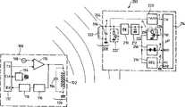
图1是本发明系统以其最普通方式的方块图,它包含一终端机和在终端机之磁场中的便携式物件。Figure 1 is a block diagram of the system of the invention in its most general form, comprising a terminal and portable objects in the magnetic field of the terminal.
图2显示图1之便携式物件的一个特定实施例。FIG. 2 shows a specific embodiment of the portable object of FIG. 1 .
图3显示图2之调节器电路之细节。FIG. 3 shows details of the regulator circuit of FIG. 2 .
图4和图5详细地显示图2之解调器电路的两种可能变化。4 and 5 show in detail two possible variations of the demodulator circuit of FIG. 2 .
图6是图5解调器电路的详细线路图。FIG. 6 is a detailed circuit diagram of the demodulator circuit of FIG. 5. FIG.
图7详细显示图2之时钟提取电路。FIG. 7 shows the clock extraction circuit in FIG. 2 in detail.
图8为一组波形图,显示便携式物件如何被遥控赋能以及此时钟信号如何被提取。FIG. 8 is a set of waveform diagrams showing how the portable object is remotely powered and how the clock signal is extracted.
图9为一组波形图,解释信息如何自终端机传送至物件。FIG. 9 is a set of waveform diagrams illustrating how information is transmitted from a terminal to an object.
图10为一系列波形图,解释信息如何自物件传送至终端机。Figure 10 is a series of waveform diagrams illustrating how information is transmitted from the object to the terminal.
图11显示经由接触和非接触,各种转换操作实施于其两种操作模式之间的双模式卡内。Fig. 11 shows that various switching operations are implemented in a dual mode card between its two modes of operation, via contact and contactless.
本发明系统的一个实施例以参考图1之方块图来作说明,在此图中,标号100指示一终端机,它可以联结至放置在其附近的便携式物件200。An embodiment of the system of the present invention is illustrated with reference to the block diagram of FIG. 1, in which
此终端机包括一发射器线圈102,它与诸如104的电容器相关联,形成一调谐电路106,经设计以产生一调制之磁感应磁场。电路106要调谐的频率可以是13.56MHz,例如,自然地不受限制的那一数值,此一特殊选择只因这样的事实而形成,即它符合由用于通信功能以及用于遥控赋能功能之欧洲标准所认可的数值。此外,此一相当高之值使其能设计电路具有拥有少许匝数的线圈,因此它很容易而且很便宜地得到实施。The terminal includes a
此调谐电路106由持续波高频振荡器108赋能,它由待发送之来自数字电路112的信号TXD所驱动的混合器级来调制。电路112之操作,以及特别是信号TXD的排序由一产生时钟信号CLK的电路114来计时。The
接收器级,包含一高频解调器电路116,连同副载波解调器电路118,以下文所说明之方法,当它业已决定在便携式物件至终端机之方向中使用副载波调制时,自横越线圈102之接头所拾取之信号提取接收的数据RXD,(此一技术自然地未局限于任何方法,调制同样地可以是在基带中实施)。The receiver stage, comprising a high
便携式物件200包括一线圈202与电子电路204合作,有利的是在完全集成化的单片技术中实现,以便能使物体成为小尺寸,典型地有一“信用卡”之格式。通过举例方式,此线圈202为印刷线圈,以及此组电路204按“专用集成电路”形式实施。
线圈202与一电容器206合作以形成一谐振电路208调谐至一指定频率(例如,13.56MHz)能双向地与终端机以所谓“感应”技术交换数据,并亦能使物件由线圈202所拾取之磁场,亦即,由用作互换信息之线圈的相同线圈予以遥控地赋能。The
跨越调谐电路208接头拾取的交流电压a加到一半波或全波整流器级210,紧接以一滤波器级212以传送一滤波之整流电压b。The AC voltage a picked up across the
此便携式物件亦包括一数字处理级214,典型地以微处理器、随机存取存储器,只读存储器以及电可擦可编程只读存储器以及接口电路为基础而实现。The portable object also includes a
自整流器和滤波器级210和212之下游,呈并联地连接各级专用电路,包含:Downstream from the rectifier and
一电压稳定调节器级216,在其输出处传送一直流电压d,此电压业经整流,滤波及稳定化,同时它特别适用于数字电路214之正极电源接头VCC,其另一电源接头为接地线GND。此一稳定化级216可以是一传统类型的电压稳定器,或者,在一无限制变换中,如以下参照图2和图3说明的指定电路。A voltage stabilizing
一解调器级218,接收此信号b作为其输入,并在其输出处产生一解调信号e,此信号加到数字电路214的数据输入RXD。特别是,此解调器可以是一解调器检测振幅变化和/或具有一可变阈值,如以下参照图4、5和6详细说明。A
一时钟提取器级,其输入接收自调谐电路208之接头提取的信号a,其输出产生一信号c加到数字电路的时钟输入。A clock extractor stage whose input receives the signal a extracted from the connection of the
此时钟提取器级220可以放置在或者自整流器和滤波器级210和212之上游如图所示,或者自该级之下游,亦即,它可操作在信号b上取代信号a;虽然如此,但当时钟提取器随后需要有较大灵敏度以便能补偿由滤波器级所进行的对信号的平滑时,利用信号b极少有利。This
一调制器级222,它通过“负载调制”以传统方法来操作,此负载调制为一种技术,它促使电流由调谐电路208抽取,此电路位于由终端机所产生之周围磁场中以受控方式变化。A
此调制器级222包括一电阻元件224(一分立电阻器元件,或者采用单片技术,没有栅极的MOS型组件,并用作一电阻)与转换元件(一MOS晶体管)226呈串联连接,后者由呈现在数字电路214输出TXD上的调制信号f所控制。在一变换中,取代被放置在自整流器和滤波器电路210和212之下游的,可将调制器级222同等好地放置在自该电路之上游,如图1内222′调制器所示,即,它可以是直接地连接至共振电路208的接头。This
此一方式中建议的一般性结构以及其中此解调器级位于自整流器和滤波器级210和212之下游,具有对信号中之瞬间变化减小灵敏度之优点。The general structure suggested in this approach, and in which the demodulator stage is located downstream of the self-rectifier and filter
对遥控赋能的便携式物件,在一已整流及已滤波之信号上实施解调,使其可能以在一振荡循环中减少电源中瞬间变化之影响。For remote-enabled portable objects, demodulation is performed on a rectified and filtered signal, making it possible to reduce the effects of momentary changes in power during an oscillation cycle.
此观点将可自下列参照图8之波形图对解调器操作的详细说明中有较佳之了解。This point will be better understood from the following detailed description of the operation of the demodulator with reference to the waveform diagram of FIG. 8 .
图1所示结构之一特殊实施例可参照图2说明如下,该实施例的特征为给予此调节器级216的特殊结构,详细说明如下的是一“分路调节器”级,此分路调节器有一分路组件228用以按受控方法自数字电路214分流电源电流。此分路组件与电路214呈并联地连接于电源和接地接头VCC和GND之内,并与放置在自调节器组件228之上游电源线VCC内之一串联电阻元件230相关联。A particular embodiment of the structure shown in FIG. 1 can be described below with reference to FIG. 2. The feature of this embodiment is the special structure given to the
此分路228可以有利地为一齐纳二极管,或者与齐纳二极管等同功能的分立或集成组件,例如自National Semi-Conductor Corporation的LM185/LM285/LM385系列中的组件,该组件组成一基准电压(一电压为固定或可调整,视组件而定),同时吸取仅20μA之一偏压电流,有非常低的动态阻抗和20μA至20mA之操作电流范围。此组件228也可以按ASIC(专用集成电路)集成为电压基准组件的单片等效电路。This shunt 228 may advantageously be a Zener diode, or a discrete or integrated component functionally equivalent to a Zener diode, such as components from the LM185/LM285/LM385 series from National Semi-Conductor Corporation, which components form a reference voltage ( One voltage is fixed or adjustable, depending on the device), while drawing a bias current of only 20μA, has very low dynamic impedance and an operating current range of 20μA to 20mA. This component 228 can also be integrated as a monolithic equivalent of a voltage reference component in an ASIC (Application Specific Integrated Circuit).
图3显示使用上述一类组件的此电路216的特殊实施例,其电压基准输入234通过连接于VCC和接地线之间的分压器电桥236,238偏压至一预定值。Figure 3 shows a particular embodiment of this
电阻元件230可以是一分立电阻器,或者有利地是一集成单片组件,例如,一MOS元件作用如一电阻象组件214一样。
有利地是一转换组件诸如一MOS晶体管240也经提供,并通过施加于其栅极之信号INH保持在正常操作中的导电状态,此一晶体管可以通过施加简单控制信号INH(特别是在计算电路214的软件控制下)具有禁止分路调节器操作的效力而转换至非导电状态,这样此电路就如调节器业经省略的状态。Advantageously a switching element such as a MOS transistor 240 is also provided and is kept in the conducting state in normal operation by the signal INH applied to its gate, this transistor can be controlled by applying a simple control signal INH (especially in the
特别是当人们希望用高压向微处理器供电,同时避免冒破坏此调节器级之危险时可以使用禁止分路调节器之能力。The ability to disable shunt regulators is especially useful when one wishes to power a microprocessor with high voltage without risking damage to the regulator stage.
此一情况特别是在为测试目的时发生,或者当便携式物件为一双模式物件能在非接触模式(调节器在使用中)或接触模式(调节器被禁止)中作选择性使用时,此调整电源电压随后被直接地施加于便携式物体触点之一而匆须有任何实施特定调整之需要,如以遥控赋能一样。This situation occurs especially for testing purposes, or when the portable object is a dual-mode object that can be selectively used in non-contact mode (adjustment is in use) or contact mode (adjustment is disabled). The supply voltage is then applied directly to one of the portable object contacts without any need to implement specific adjustments, as with remote control enabling.
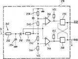
以下参照图4至6详细说明振幅解调器级218。The
此振幅解调器为适用于处理调制信号的电路,其中调制深度较低。“调制之低深度”或“低调制”一词意指以一比率调制,典型地小于或等于50%,较佳地小于20%,此比率限定为考虑之信号的最大和最小振幅Amax和Amin的(Amax-Amin)/(Amax+Amin)。The amplitude demodulator is a circuit suitable for processing modulated signals, where the modulation depth is low. The term "low depth of modulation" or "low modulation" means modulation with a ratio, typically less than or equal to 50%, preferably less than 20%, defined by the maximum and minimum amplitudes Amax and Amin of the signal under consideration (Amax-Amin)/(Amax+Amin).
一遥控赋能便携式物件的特殊上下文中,有利者为对电源进行限制,以使用一低调制比率以便能确保当调制处于低状态中时有充分的电力于此时期中可用,因为振幅调制的效果促使传送至便携式物件之瞬间电力直接地随调制电位而变化。In the particular context of a remote-enabled portable object, it is advantageous to limit the power supply to use a low modulation ratio to ensure that sufficient power is available for periods when the modulation is in the low state because of the effect of the amplitude modulation The instantaneous power that is caused to be delivered to the portable object varies directly with the modulating potential.
图4显示第一种可能的变化,其中此解调器为一自适应解调器具有可变阈值。Figure 4 shows a first possible variation, where the demodulator is an adaptive demodulator with variable thresholds.
一选择性低通滤波器级242之后,此电路包含一比较器244,适当地有磁滞现象,以其正输入接收待解调信号b予以解调(此处由级242适当地滤波),并以其负输入接收相同信号b,但在它已传送通过一阻容级246、248之后作用如积分器。比较因此实施于信号之瞬间值和信号之平均值之间,它构成此可变比较阈值。After a selective low-
图5显示解调器218的第二种可能变化,在此情况中它是对振幅之变化灵敏的解调器。Figure 5 shows a second possible variation of the
在一选择性低通滤波器级242之后,此信号b施加于阻容级250、252作用如一微分器。此信号输出由此施加于比较器244的正极接头(此情况中同样适当地有磁滞现象),其负极输入连接至一固定电位,例如接地。在此情况中,此解调器可响应振幅上变化(因为此微分器级),而与信号的平均值无关;此比较器仅检测平均值上之变化。After a selective low-
图6显示用以检测振幅上变化之此类解调器电路的一更详细实施例。除了由电阻器252和电容器254所构成之低通滤波器242以外,有一串联之电容器250作用如一微分器与电阻器256至264相组合。以此方式微分的信号加至两个对称的比较器244和266,其输出作用在两个交叉耦联的双稳定器268和270经组织以产生两个适当构形的对称信号RXD和RXD。Figure 6 shows a more detailed embodiment of such a demodulator circuit to detect changes in amplitude. In addition to the
图7显示时钟检测器和提取器电路220之一实施例。One embodiment of clock detector and
在其输入上,此一电路接收取自谐振电路208之接头的信号,同时它施加于具有磁带现象的比较器272的微分输入,它产生时钟信号(CLK)。此时钟信号也施加于“异一或”门274的两个输入,直接地加至输入之一以及经由阻容电路276,278而加至另一输入上。此阻容电路施加一延递至信号于其拾取时,该延递经选择以有一1/4fclk之顺序之时间常数(此处fclk为由终端机100之电路114所产生之时钟的频率)。自门274之输出信号随后由一阻容电路280、282平均,此电路有一时间常数较1/2fclk为大(适当地大约1/fclk),并随后施加于比较器284之输入之一,用以与一固定之阈值S作比较。At its input, this circuit receives the signal taken from the connection of the
此时钟信号CLK用以对数字处理机电路214施加适当的时钟脉冲,同时自比较器280的输出给予一信号PRSCLK指示时钟信号是否出现。The clock signal CLK is used to apply the appropriate clock pulses to the
对适用以同样地操作良好的“非接触”模式和“接触”模式的一双模式卡,此信号PRSCLK指示时钟信号是否出现或未出现,有利地用以通知数字电路该便携式物件是在“非接触”型环境中,并决定相应之动作,诸如选择一适当之通信规程,以及启动分路调节器,PRSCLK信号用以产生INH(参考上面如图3说明)等。For a dual-mode card that operates equally well in both "contactless" and "contact" modes, this signal PRSCLK indicates whether the clock signal is present or absent, advantageously used to inform the digital circuitry that the portable object is in "contactless" mode. " type environment, and determine the corresponding actions, such as selecting an appropriate communication protocol, and starting the shunt regulator, the PRSCLK signal is used to generate INH (refer to the illustration in Figure 3 above) and so on.
图11详细地显示各种不同的转换器,它们自动地以此一方式操作于“非接触”模式和“接触”模式之间。触点286如下:时钟(CLK),接地线(GND),数据(I/O),电源(VCC),复位至零RST,符合国际标准化组织(ISO)之标准,进一步之细节可参考此标准。此各种转换器288至296均显示在接触位置中(以“O”指示),此为缺省位置,同时它们在信号PRSCLK之控制下改变至“非接触”位置(“1”指示),此信号由电路220产生,并指示该时钟信号来自整流器和滤波器装置。Figure 11 shows in detail the various switches which operate in this manner automatically between a "non-contact" mode and a "contact" mode. Contact 286 is as follows: clock (CLK), ground (GND), data (I/O), power (VCC), reset to zero RST, in line with the standard of the International Organization for Standardization (ISO), further details can refer to this standard . The
当希望实施未在基带中的调制,而是副载波调制时,时钟信号之提取亦特别地有利,因为此副载波容易通过对时钟频率的分频而产生。此数字电路214随后将以此方式产生的副载波施加到供发送的数据,以便能产生信号TXD,此信号施加于负载调制器电路222。The extraction of the clock signal is also particularly advantageous when it is desired to implement modulation not in baseband, but subcarrier modulation, since this subcarrier is easily generated by division of the clock frequency. This
作为变换,可以检测接触区CLK上而不是来自线圈(时钟提取器)之信号中时钟信号的出现。这就要求转换双稳态288至296的操作并增加时钟出现检测器,将接触区CLK用作其输入并产生信号PRSCLK作为提取器220的替换。As an alternative, the presence of a clock signal can be detected on the contact area CLK rather than in the signal from the coil (clock extractor). This requires switching the operation of the
然而,这种变换存在各种缺陷。因此,如果按照ISO标准7816用接触模式进行通信,时钟信号仅仅当电压已经出现在其它接触区之后才出现,而且可以要求合适的测量以避免分路调节器(来自线圈的远距离赋能)在开始接触通信时超载Vcc。However, this conversion suffers from various drawbacks. Therefore, if communicating in contact mode according to ISO standard 7816, the clock signal appears only after the voltage has appeared on the other contact area, and appropriate measurements may be required to avoid shunt regulators (remote energization from coils) at Overload Vcc when starting contact communication.
便携式装置的操作参照图8至10的波形图。说明如下。The operation of the portable device refers to the waveform diagrams of FIGS. 8 to 10 . described as follows.
说明以参照图8起始,解释此物件如何被赋能,以及它如何发现此时钟信号。The description begins with reference to FIG. 8, explaining how the object is enabled and how it detects the clock signal.
调谐电路208拾取一部分由终端机所产生的磁能量。此磁能量相当于示于图8内的交流信号a,它由方块210整流并由电容器212滤波如图8所示提供经整流和滤波的电压b。对一有一峰值电压10伏特的交流信号a言,获得一整流及滤波电压有大约8.5V的峰值电压。自然地,此电压a之振幅,以及由此产生之电压b,大部分取决于物件和终端机之间的距离,当物件对终端机愈接近振幅即增加。此调节器级216用以为此变化作补偿,通过传送一稳定电压至数字电路214,典型地为3V范围的电压(图8内波形d)。The
因此,当可远离终端机时,特别是在其范围之边缘时,此电压b将相当地接近于3V之要求值,以及b和d之间电压降将极小,传送通过此分路228之电流亦非常小,以及大体上所有由电源电路输送之电流将用作赋能此数字电路214。可见,在此情况下流过此分路228的电流可以低到仅少许微安培(最小偏置电流)。Therefore, when the terminal can be far away, especially at the edge of its range, this voltage b will be quite close to the required value of 3V, and the voltage drop between b and d will be extremely small, and the transmission through this shunt 228 The current is also very low, and substantially all of the current delivered by the power circuit will be used to power the
相反地,当此物件非常接近于终端机时,此电压b将为高,以及b和d之间的电位差将亦甚大(若干伏特),因此流过此分路228的电流将很高,电阻元件230和分路228随后耗散此过量电力。Conversely, when the object is very close to the terminal, the voltage b will be high, and the potential difference between b and d will be very large (several volts), so the current flowing through the shunt 228 will be high,
除了其稳定至数字电路214的电源的纯电功能外,此分路调节器级亦对上述电路之情况提供若干有利点。In addition to its purely electrical function of stabilizing the power supply to the
首先,当此物件接近此终端机时,因为低负载呈现于自调谐电路208之下游,它将使其能限制b处并因此而在a处电压的漂移,因为大电流流过此分路,所拾取但并非要求向数字电路214供的电力完全呈热的形式发散。Firstly, when the object is close to the terminal, since a low load is present downstream of the self-tuning
当调谐电路208的电容器206是以集成单片技术所实施之元件时,那将是特别地有利,因为此将避免由于过量电压使电容器毁坏之危险。由于对集成电路的几何形状的约束,不可能使电容器具有高击穿电压。不幸的是,由于此数字电路214是围绕微处理器构成,它需要一较大电力供应,并因此要有高电位磁场,该磁场因此在调谐电路中产生过剩电压,除非所提及之防范措施已经执行。It is particularly advantageous when the
第二,更详细解释,此分路调节器具有对流向数字电路的电源电流的瞬间变化进行平滑的效果(此电路的功耗不恒定),并具有避免它们对用于自物件至终端机或自终端机至物件之任一通信之电路的其他构件之操作有反应之效果。电流上或电压上不理想之变化可引发调制或解调中的错误。Second, to explain in more detail, this shunt regulator has the effect of smoothing the momentary changes in the supply current to the digital circuit (the power consumption of this circuit is not constant), and has the effect of preventing them from being used from the object to the terminal or The operation of other components of the circuit for any communication from the terminal to the object has reactive effects. Undesirable changes in current or voltage can cause errors in modulation or demodulation.
最后,当物件位于自终端机之终极范围处时,并因此仅自终端机接收刚好够用之信号用以赋能此数字电路时,电路之此设计用以避免耗费任何电力,由于流过此分路220之电流实际上为零。因此,所有由调谐电路所拾取之电力适用于赋能此数字电路。Finally, the circuit is designed so as not to consume any power since the The current in
此时钟提取器电路220用以变换横越调谐电路208所拾取之交流电流a成为一串取之适当构件的时钟脉冲c。The
信息自终端机传送至物件之方式以参照图9之波形图而说明如下。The way information is transmitted from the terminal to the object is described below with reference to the waveform diagram of FIG. 9 .
要传送信息至物件,此终端机调制它产生的磁场之振幅。由于此信息呈二进制形态传送,该调制量将信号振幅减少一个预定量,例如至10%。此一减小,例如,相当于发送一逻辑“0”,其振幅仍保留于其为一逻辑“1”之最大处。这可以在图9内如由调谐电路208所拾取之信号的波形图a上见到。To transmit information to an object, the terminal modulates the amplitude of the magnetic field it generates. Since this information is transmitted in binary form, the modulator reduces the signal amplitude by a predetermined amount, for example to 10%. This reduction is, for example, equivalent to sending a logic "0" whose amplitude remains at its maximum for a logic "1". This can be seen in FIG. 9 as waveform diagram a of the signal picked up by the
当整流和滤波之后,在b处引起整流及滤波之信号的振幅下降。此振幅下降由振幅解调器218所控制,它输出此逻辑信号e,此信号施加于数字电路。After rectification and filtering, at b causes the amplitude of the rectified and filtered signal to drop. The amplitude reduction is controlled by the
显然,因对终端机发送的信号进行调制而产生的振幅下降,对时钟提取器上(信号c),或对传送至数字电路(信号d)的电源电压,没有影响。Obviously, the drop in amplitude due to the modulation of the signal sent by the terminal has no effect on the clock extractor (signal c), or on the supply voltage delivered to the digital circuit (signal d).
如果不同于调幅之技术使用于终端机至物件方向时,例如相位调制如在若干早期文件中所教导时,那么此类调制没有直接影响到本发明之调节器电路的操作;虽然如此,但当振幅调制使用时,如所解释,由于完全地具有抗拒各种与选择振幅调制技术相关联之缺点之能力者,故此一电路为特别地有利。If techniques other than amplitude modulation are used in the terminal-to-object direction, such as phase modulation as taught in several earlier documents, then such modulation does not directly affect the operation of the regulator circuit of the present invention; nevertheless, when When used with amplitude modulation, as explained, such a circuit is particularly advantageous due to its ability to completely counteract the various disadvantages associated with alternative amplitude modulation techniques.
以下参照图10之波形图说明信息自物件回送至终端机的方式。The manner in which information is sent back from the object to the terminal is described below with reference to the waveform diagram of FIG. 10 .
如上所述,在所示之实施例中,传输是通过负载变化而实施,亦即,通过由调谐电路208所吸收之电流的受控变化。最终,此电阻元件224通过此组件226而选择性地转换入电路中;例如,当逻辑“0”要发送时置于电路中,为逻辑“1”时则在电路外。As mentioned above, in the illustrated embodiment, transmission is effected by a load change, ie, by a controlled change in the current drawn by the
当此电阻器在电路中时,亦即,为一逻辑“0”时,此电压a因为额外之负载而下降。此电阻器之电阻自然地被选择,使此一电压降无论如何能使适当电力供应至数字电路予以保存。When the resistor is in the circuit, ie at a logic "0", the voltage a drops due to the additional load. The resistance of this resistor is naturally chosen such that this voltage drop will nevertheless enable the proper power supply to the digital circuit to be preserved.
虽然如此,当在距终端机之极端范围时仍可能有困难。在此环境下,需要通过此电阻元件224予以分流以产生此调制的电流可能太高而不能容许此数字电路继续适当地操作。Even so, there may still be difficulties when working at extreme ranges from the terminal. Under such circumstances, the current that needs to be shunted through the
在此一情况下,以及在此物件开始发送信息至终端机之前,最好为数字电路置于一“低功耗”模式形成一准备,以便能在电阻元件224内消耗更多电流而不会连累对数字电路之电力供应。In this case, and before the object starts sending information to the terminal, it is preferable to make provision for the digital circuit to be placed in a "low power" mode, so that more current can be drawn in the
例如,此将可以通过数字电路中微处理器的程序来实现,在开始发送数据至终端机之前,将传输例行程序置于随机存取存储器中(在存取上它消耗极少电力),并中断电可擦可编程只读存储器(它在存取上消耗可观之更多电力)。换言之,此数字电路置于“低功耗”模式中以便使大量电流可用,此电流随后在调制电阻器中消耗用以发送信息至终端机。This would be possible, for example, by programming a microprocessor in a digital circuit, placing the transmission routine in random access memory (which consumes very little power on access) before starting to send data to the terminal, And interrupt EEPROM (which consumes considerably more power on access). In other words, the digital circuit is placed in a "low power" mode so that a large amount of current is available, which is then consumed in the modulating resistor to send information to the terminal.
同时,如果更多调制电流可以传送通过此电阻元件224(给予它以低电阻),那么此调制将由终端机更好地感知,因此使其可能在终端机处以检测装置来执行任务,因此使其可能不复杂和/或提供一较佳信/噪比。At the same time, if more modulation current could be passed through this resistive element 224 (giving it a low resistance), then this modulation would be better sensed by the terminal, thus making it possible to perform tasks with detection means at the terminal, thus making it May be less complex and/or provide a better signal/noise ratio.
仍然在物件至终端方向中,可以使用其他类型之调制,或使用各种变换,例如,如上所述,一副载波之调制,它控制负载变化以取代直接由待传输之信号调制负载。Still in the object-to-terminal direction, other types of modulation can be used, or various transformations can be used, for example, as mentioned above, modulation of a subcarrier which controls the load variation instead of modulating the load directly by the signal to be transmitted.
Claims (12)
Translated fromChineseApplications Claiming Priority (2)
| Application Number | Priority Date | Filing Date | Title |
|---|---|---|---|
| FR96/15163 | 1996-12-10 | ||
| FR9615163AFR2756953B1 (en) | 1996-12-10 | 1996-12-10 | PORTABLE TELEALIMENTAL OBJECT FOR CONTACTLESS COMMUNICATION WITH A TERMINAL |
Publications (2)
| Publication Number | Publication Date |
|---|---|
| CN1214136Atrue CN1214136A (en) | 1999-04-14 |
| CN1150488C CN1150488C (en) | 2004-05-19 |
Family
ID=9498514
Family Applications (2)
| Application Number | Title | Priority Date | Filing Date |
|---|---|---|---|
| CNB971932069AExpired - LifetimeCN1150488C (en) | 1996-12-10 | 1997-12-08 | System for exchanging data between terminal and remotely energized IC card by contactless communication |
| CN97193205APendingCN1214135A (en) | 1996-12-10 | 1997-12-10 | Data exchange system by contactless communication between terminal and remote powered portable objects |
Family Applications After (1)
| Application Number | Title | Priority Date | Filing Date |
|---|---|---|---|
| CN97193205APendingCN1214135A (en) | 1996-12-10 | 1997-12-10 | Data exchange system by contactless communication between terminal and remote powered portable objects |
Country Status (22)
| Country | Link |
|---|---|
| US (1) | US6636146B1 (en) |
| EP (2) | EP0901670B1 (en) |
| JP (4) | JP2001502833A (en) |
| KR (2) | KR100471655B1 (en) |
| CN (2) | CN1150488C (en) |
| AR (2) | AR010756A1 (en) |
| AT (1) | ATE271242T1 (en) |
| AU (2) | AU728953B2 (en) |
| BR (2) | BR9707629B1 (en) |
| CA (2) | CA2245912C (en) |
| DE (1) | DE69729865T2 (en) |
| DK (1) | DK0901670T3 (en) |
| EA (2) | EA001127B1 (en) |
| ES (1) | ES2224280T3 (en) |
| FR (1) | FR2756953B1 (en) |
| IL (2) | IL125715A (en) |
| MX (1) | MXPA98006460A (en) |
| PT (1) | PT901670E (en) |
| TR (2) | TR199801538T1 (en) |
| TW (2) | TW387190B (en) |
| UA (1) | UA57016C2 (en) |
| WO (2) | WO1998026370A1 (en) |
Cited By (10)
| Publication number | Priority date | Publication date | Assignee | Title |
|---|---|---|---|---|
| CN100459370C (en)* | 2005-09-13 | 2009-02-04 | Lg电子株式会社 | Electrical power generator, mobile terminal provided with the same and control method thereof |
| CN101167083B (en)* | 2005-04-28 | 2010-12-22 | Nxp股份有限公司 | Circuit for a communication device and method of controlling a transmission |
| WO2011020326A1 (en)* | 2009-08-18 | 2011-02-24 | 厦门盛华电子科技有限公司 | Method and device for detecting and controlling card-reading distance of handset radio frequency (rf) card |
| CN1816973B (en)* | 2003-06-30 | 2011-04-06 | 索尼株式会社 | data communication equipment |
| CN102106054A (en)* | 2007-03-22 | 2011-06-22 | 鲍尔马特有限公司 | Signal transfer system |
| CN102725939A (en)* | 2009-09-22 | 2012-10-10 | 波尔基斯公司 | Inductive power supply |
| US8614526B2 (en) | 2007-09-19 | 2013-12-24 | Qualcomm Incorporated | System and method for magnetic power transfer |
| CN107078554A (en)* | 2014-09-03 | 2017-08-18 | 皇家飞利浦有限公司 | Wireless Inductive Power Transfer |
| US11114895B2 (en) | 2007-01-29 | 2021-09-07 | Powermat Technologies, Ltd. | Pinless power coupling |
| US20220263346A1 (en)* | 2009-06-16 | 2022-08-18 | The Board Of Trustees Of The Leland Stanford Junior University | Method of making and using an apparatus for a locomotive micro-implant using active electromagnetic propulsion |
Families Citing this family (131)
| Publication number | Priority date | Publication date | Assignee | Title |
|---|---|---|---|---|
| US6390210B1 (en) | 1996-04-10 | 2002-05-21 | Smith International, Inc. | Rolling cone bit with gage and off-gage cutter elements positioned to separate sidewall and bottom hole cutting duty |
| FR2756953B1 (en)* | 1996-12-10 | 1999-12-24 | Innovatron Ind Sa | PORTABLE TELEALIMENTAL OBJECT FOR CONTACTLESS COMMUNICATION WITH A TERMINAL |
| US6054925A (en)* | 1997-08-27 | 2000-04-25 | Data Investments Limited | High impedance transponder with improved backscatter modulator for electronic identification system |
| FR2782209A1 (en)* | 1998-08-06 | 2000-02-11 | Innovatron Electronique | Inductively-read transponder for access control or payment, switches in capacitor to detune resonant circuit if supply voltage derived from read signal is excessive |
| FR2790154A1 (en)* | 1999-02-23 | 2000-08-25 | Innovatron Electronique | Terminal for contactless communication by induction with portable objects, comprising phase demodulation detector |
| US7212414B2 (en) | 1999-06-21 | 2007-05-01 | Access Business Group International, Llc | Adaptive inductive power supply |
| US7522878B2 (en) | 1999-06-21 | 2009-04-21 | Access Business Group International Llc | Adaptive inductive power supply with communication |
| FR2808634A1 (en) | 2000-05-05 | 2001-11-09 | St Microelectronics Sa | IMPROVED DEMODULATION CAPACITY OF AN ELECTROMAGNETIC TRANSPONDER |
| EP1158601A1 (en) | 2000-05-15 | 2001-11-28 | Häni Prolectron Ag | Support device with an antenna with low sensitivity |
| GB2363498B (en) | 2000-06-16 | 2005-06-01 | Marconi Caswell Ltd | Transponder device for generating a data bearing output |
| AU2001294713A1 (en)* | 2000-09-29 | 2002-04-08 | Microchip Technology Incorporated | Method and apparatus for detuning a resonant circuit of a remotely powered device |
| KR20020033328A (en)* | 2000-10-30 | 2002-05-06 | 김정태 | Card reader of contactless type |
| EP1221678A1 (en)* | 2001-01-09 | 2002-07-10 | Telectronic SA | Receiver for sensing an electromagnetic signal and device using such a receiver |
| US7079864B2 (en)* | 2001-05-17 | 2006-07-18 | Wildseed, Ltd. | Adding peripheral devices to mobile devices via smart interchangeable cover |
| US6920338B2 (en)* | 2001-05-17 | 2005-07-19 | Wildseed, Ltd. | Adding I/O ports to mobile device via smart interchangeable cover |
| US20030073462A1 (en)* | 2001-05-17 | 2003-04-17 | Peter Zatloukal | Adding control keys to mobile device via smart interchangeable cover |
| US20030104791A1 (en)* | 2001-05-17 | 2003-06-05 | Engstrom G. Eric | Adding peripherals to mobile device via smart interchangeable cover |
| EP1474776B1 (en)* | 2002-02-01 | 2008-11-26 | Nxp B.V. | Adapting coil voltage of a tag to field strength |
| DE10206676A1 (en)* | 2002-02-18 | 2003-08-28 | Giesecke & Devrient Gmbh | Switching device operable with a transponder |
| GB0206982D0 (en)* | 2002-03-25 | 2002-05-08 | Melexis Nv | Temperature sensitive radio frequency device |
| JP3724450B2 (en)* | 2002-04-23 | 2005-12-07 | 株式会社村田製作所 | High frequency circuit for wireless communication and communication device including the same |
| KR100486938B1 (en)* | 2002-05-16 | 2005-05-03 | 한국전자통신연구원 | Combination type IC card |
| JP4558259B2 (en)* | 2002-05-23 | 2010-10-06 | シャープ株式会社 | Combination IC card |
| FR2834148A1 (en)* | 2002-05-31 | 2003-06-27 | Siemens Vdo Automotive | Car hands free access communication system having coded signal transmission car receiver sent with coding amplitude modulation index below ten per cent. |
| FR2840742A1 (en)* | 2002-06-06 | 2003-12-12 | St Microelectronics Sa | ELECTROMAGNETIC TRANSPONDER READER |
| US6954053B2 (en)* | 2002-07-10 | 2005-10-11 | Atmel Corporation | Interface for shunt voltage regulator in a contactless smartcard |
| US7792759B2 (en)* | 2002-07-29 | 2010-09-07 | Emv Co. Llc | Methods for performing transactions in a wireless environment |
| NZ528542A (en) | 2003-09-29 | 2006-09-29 | Auckland Uniservices Ltd | Inductively-powered power transfer system with one or more, independently controlled loads |
| JP4036813B2 (en)* | 2003-09-30 | 2008-01-23 | シャープ株式会社 | Non-contact power supply system |
| US7917088B2 (en)* | 2004-04-13 | 2011-03-29 | Impinj, Inc. | Adaptable detection threshold for RFID tags and chips |
| EP1774648B1 (en)* | 2004-07-13 | 2010-09-15 | Nxp B.V. | Demodulator for amplitude-modulated signals |
| JP4763332B2 (en) | 2004-09-03 | 2011-08-31 | 株式会社エヌ・ティ・ティ・ドコモ | Mobile terminal device, contactless card function management system, and contactless card function acquisition system |
| FR2875975B1 (en)* | 2004-09-27 | 2009-05-15 | Commissariat Energie Atomique | NON-CONTACT DEVICE FOR EXTENDING PRIVACY |
| FR2879382A1 (en)* | 2004-12-14 | 2006-06-16 | St Microelectronics Sa | ERROR DETECTION IN AN AMPLITUDE MODULATION SIGNAL |
| US20060133633A1 (en)* | 2004-12-17 | 2006-06-22 | Nokia Corporation | Mobile telephone with metal sensor |
| US7760073B2 (en)* | 2005-01-04 | 2010-07-20 | Battelle Memorial Institute | RFID tag modification for full depth backscatter modulation |
| US7689195B2 (en)* | 2005-02-22 | 2010-03-30 | Broadcom Corporation | Multi-protocol radio frequency identification transponder tranceiver |
| US7602158B1 (en)* | 2005-03-21 | 2009-10-13 | National Semiconductor Corporation | Power circuit for generating non-isolated low voltage power in a standby condition |
| US7728713B2 (en)* | 2005-05-06 | 2010-06-01 | Intelleflex Corporation | Accurate persistent nodes |
| JP5430050B2 (en)* | 2005-06-24 | 2014-02-26 | フェリカネットワークス株式会社 | Data communication system, device for executing IC card function, control method therefor, and information processing terminal |
| US7817015B1 (en)* | 2005-09-29 | 2010-10-19 | Tc License Ltd. | Floating threshold for data detection in a RFID tag |
| DE102006001504A1 (en)* | 2006-01-11 | 2007-07-12 | Infineon Technologies Ag | Identification data carrier, reading device, identification system and method for producing an identification data carrier |
| US9130602B2 (en) | 2006-01-18 | 2015-09-08 | Qualcomm Incorporated | Method and apparatus for delivering energy to an electrical or electronic device via a wireless link |
| US8447234B2 (en)* | 2006-01-18 | 2013-05-21 | Qualcomm Incorporated | Method and system for powering an electronic device via a wireless link |
| JP4355711B2 (en)* | 2006-04-20 | 2009-11-04 | フェリカネットワークス株式会社 | Information processing terminal, IC card, portable communication device, wireless communication method, and program |
| FR2908205B1 (en) | 2006-11-03 | 2009-02-27 | Xiring Sa | DEVICE FOR PROTECTING FRAUD FROM CONTACTLESS COMMUNICATION OBJECTS |
| US9143009B2 (en)* | 2007-02-01 | 2015-09-22 | The Chamberlain Group, Inc. | Method and apparatus to facilitate providing power to remote peripheral devices for use with a movable barrier operator system |
| US8378523B2 (en) | 2007-03-02 | 2013-02-19 | Qualcomm Incorporated | Transmitters and receivers for wireless energy transfer |
| US8482157B2 (en) | 2007-03-02 | 2013-07-09 | Qualcomm Incorporated | Increasing the Q factor of a resonator |
| US9774086B2 (en) | 2007-03-02 | 2017-09-26 | Qualcomm Incorporated | Wireless power apparatus and methods |
| US9124120B2 (en) | 2007-06-11 | 2015-09-01 | Qualcomm Incorporated | Wireless power system and proximity effects |
| JP2009027781A (en) | 2007-07-17 | 2009-02-05 | Seiko Epson Corp | Power reception controller, power receiver, contactless power transmitting system, charge controller, battery device, and electronic equipment |
| WO2009036405A1 (en) | 2007-09-13 | 2009-03-19 | Nigelpower, Llc | Maximizing power yield from wireless power magnetic resonators |
| JP5362733B2 (en) | 2007-10-11 | 2013-12-11 | クゥアルコム・インコーポレイテッド | Wireless power transfer using a magneto-mechanical system |
| US9264231B2 (en) | 2008-01-24 | 2016-02-16 | Intermec Ip Corp. | System and method of using RFID tag proximity to grant security access to a computer |
| CN102084442B (en) | 2008-03-17 | 2013-12-04 | 鲍尔马特技术有限公司 | Inductive transmission system |
| US8629576B2 (en) | 2008-03-28 | 2014-01-14 | Qualcomm Incorporated | Tuning and gain control in electro-magnetic power systems |
| JP4631935B2 (en)* | 2008-06-06 | 2011-02-16 | ソニー株式会社 | Information processing apparatus, information processing method, program, and communication system |
| US8981598B2 (en) | 2008-07-02 | 2015-03-17 | Powermat Technologies Ltd. | Energy efficient inductive power transmission system and method |
| US11979201B2 (en) | 2008-07-02 | 2024-05-07 | Powermat Technologies Ltd. | System and method for coded communication signals regulating inductive power transmissions |
| JP2012501500A (en)* | 2008-08-26 | 2012-01-19 | クゥアルコム・インコーポレイテッド | Parallel wireless power transfer and near field communication |
| JP5245690B2 (en)* | 2008-09-29 | 2013-07-24 | 株式会社村田製作所 | Contactless power receiving circuit and contactless power transmission system |
| JP5347813B2 (en)* | 2009-08-03 | 2013-11-20 | ソニー株式会社 | Communication apparatus and communication method |
| KR101249736B1 (en) | 2009-09-07 | 2013-04-03 | 한국전자통신연구원 | Textile-based magnetic field interface clothes and mobile terminal in wearable computing system |
| US8643356B2 (en)* | 2009-10-06 | 2014-02-04 | Infineon Technologies Ag | Voltage regulation and modulation circuit |
| US20110164471A1 (en)* | 2010-01-05 | 2011-07-07 | Access Business Group International Llc | Integrated wireless power system |
| JP5499716B2 (en)* | 2010-01-06 | 2014-05-21 | 日本電気株式会社 | Semiconductor device |
| US20110217926A1 (en)* | 2010-03-03 | 2011-09-08 | Qualcomm Incorporated | Reverse link signaling via impedance modulation |
| US9099885B2 (en)* | 2011-06-17 | 2015-08-04 | Semiconductor Energy Laboratory Co., Ltd. | Wireless power feeding system |
| JP6016596B2 (en) | 2011-12-07 | 2016-10-26 | 株式会社半導体エネルギー研究所 | Contactless power supply system |
| FR2992123A1 (en)* | 2012-06-13 | 2013-12-20 | St Microelectronics Rousset | ENERGY MANAGEMENT IN AN ELECTROMAGNETIC TRANSPONDER |
| DE202012012880U1 (en) | 2012-08-01 | 2014-04-22 | Phoenix Contact Gmbh & Co. Kg | coil system |
| CN103926965B (en)* | 2013-01-16 | 2016-04-27 | 上海华虹集成电路有限责任公司 | Automatic biasing constant current voltage stabilizing circuit |
| US9601267B2 (en) | 2013-07-03 | 2017-03-21 | Qualcomm Incorporated | Wireless power transmitter with a plurality of magnetic oscillators |
| RU2603837C2 (en)* | 2014-02-19 | 2016-12-10 | Геннадий Леонидович Багич | Method of making electronic card (electronic key) |
| US10168393B2 (en) | 2014-09-25 | 2019-01-01 | Lockheed Martin Corporation | Micro-vacancy center device |
| US9638821B2 (en) | 2014-03-20 | 2017-05-02 | Lockheed Martin Corporation | Mapping and monitoring of hydraulic fractures using vector magnetometers |
| US9829545B2 (en) | 2015-11-20 | 2017-11-28 | Lockheed Martin Corporation | Apparatus and method for hypersensitivity detection of magnetic field |
| US10012704B2 (en) | 2015-11-04 | 2018-07-03 | Lockheed Martin Corporation | Magnetic low-pass filter |
| US9845153B2 (en) | 2015-01-28 | 2017-12-19 | Lockheed Martin Corporation | In-situ power charging |
| US9853837B2 (en)* | 2014-04-07 | 2017-12-26 | Lockheed Martin Corporation | High bit-rate magnetic communication |
| US10241158B2 (en) | 2015-02-04 | 2019-03-26 | Lockheed Martin Corporation | Apparatus and method for estimating absolute axes' orientations for a magnetic detection system |
| US9551763B1 (en) | 2016-01-21 | 2017-01-24 | Lockheed Martin Corporation | Diamond nitrogen vacancy sensor with common RF and magnetic fields generator |
| US9910104B2 (en) | 2015-01-23 | 2018-03-06 | Lockheed Martin Corporation | DNV magnetic field detector |
| US9910105B2 (en) | 2014-03-20 | 2018-03-06 | Lockheed Martin Corporation | DNV magnetic field detector |
| WO2015157290A1 (en) | 2014-04-07 | 2015-10-15 | Lockheed Martin Corporation | Energy efficient controlled magnetic field generator circuit |
| EA025461B1 (en)* | 2014-05-07 | 2016-12-30 | Научно-Производственное Общество С Ограниченной Ответственностью "Окб Тсп" | Multi-channel pulse modulator |
| KR102283255B1 (en) | 2014-10-10 | 2021-07-28 | 삼성전자주식회사 | Semiconductor device |
| WO2016118756A1 (en) | 2015-01-23 | 2016-07-28 | Lockheed Martin Corporation | Apparatus and method for high sensitivity magnetometry measurement and signal processing in a magnetic detection system |
| CN104539065B (en)* | 2015-01-26 | 2016-11-16 | 广州腾龙电子塑胶科技有限公司 | The wireless method that conducts electricity |
| WO2016190909A2 (en) | 2015-01-28 | 2016-12-01 | Lockheed Martin Corporation | Magnetic navigation methods and systems utilizing power grid and communication network |
| GB2551090A (en) | 2015-02-04 | 2017-12-06 | Lockheed Corp | Apparatus and method for recovery of three dimensional magnetic field from a magnetic detection system |
| TWI566121B (en)* | 2015-03-05 | 2017-01-11 | Intelligent components to achieve a logical dual - channel system and its methods | |
| CN106026332B (en)* | 2015-10-27 | 2019-08-27 | 天地融科技股份有限公司 | A kind of load driving circuits, method and electronic payment devices |
| WO2017087013A1 (en) | 2015-11-20 | 2017-05-26 | Lockheed Martin Corporation | Apparatus and method for closed loop processing for a magnetic detection system |
| WO2017095454A1 (en) | 2015-12-01 | 2017-06-08 | Lockheed Martin Corporation | Communication via a magnio |
| WO2017123261A1 (en) | 2016-01-12 | 2017-07-20 | Lockheed Martin Corporation | Defect detector for conductive materials |
| GB2562958A (en) | 2016-01-21 | 2018-11-28 | Lockheed Corp | Magnetometer with a light emitting diode |
| WO2017127090A1 (en) | 2016-01-21 | 2017-07-27 | Lockheed Martin Corporation | Higher magnetic sensitivity through fluorescence manipulation by phonon spectrum control |
| EP3405603A4 (en) | 2016-01-21 | 2019-10-16 | Lockheed Martin Corporation | Diamond nitrogen vacancy sensor with circuitry on diamond |
| WO2017127096A1 (en) | 2016-01-21 | 2017-07-27 | Lockheed Martin Corporation | Diamond nitrogen vacancy sensor with dual rf sources |
| WO2017127079A1 (en) | 2016-01-21 | 2017-07-27 | Lockheed Martin Corporation | Ac vector magnetic anomaly detection with diamond nitrogen vacancies |
| WO2017127098A1 (en) | 2016-01-21 | 2017-07-27 | Lockheed Martin Corporation | Diamond nitrogen vacancy sensed ferro-fluid hydrophone |
| WO2017127094A1 (en) | 2016-01-21 | 2017-07-27 | Lockheed Martin Corporation | Magnetometer with light pipe |
| DE102016106385A1 (en)* | 2016-04-07 | 2017-10-12 | Huf Hülsbeck & Fürst Gmbh & Co. Kg | Vehicle door handle with control circuit |
| US10345396B2 (en) | 2016-05-31 | 2019-07-09 | Lockheed Martin Corporation | Selected volume continuous illumination magnetometer |
| US10330744B2 (en) | 2017-03-24 | 2019-06-25 | Lockheed Martin Corporation | Magnetometer with a waveguide |
| US10317279B2 (en) | 2016-05-31 | 2019-06-11 | Lockheed Martin Corporation | Optical filtration system for diamond material with nitrogen vacancy centers |
| US20170343621A1 (en) | 2016-05-31 | 2017-11-30 | Lockheed Martin Corporation | Magneto-optical defect center magnetometer |
| US10527746B2 (en) | 2016-05-31 | 2020-01-07 | Lockheed Martin Corporation | Array of UAVS with magnetometers |
| US10408890B2 (en) | 2017-03-24 | 2019-09-10 | Lockheed Martin Corporation | Pulsed RF methods for optimization of CW measurements |
| US10345395B2 (en) | 2016-12-12 | 2019-07-09 | Lockheed Martin Corporation | Vector magnetometry localization of subsurface liquids |
| US10228429B2 (en) | 2017-03-24 | 2019-03-12 | Lockheed Martin Corporation | Apparatus and method for resonance magneto-optical defect center material pulsed mode referencing |
| US10145910B2 (en) | 2017-03-24 | 2018-12-04 | Lockheed Martin Corporation | Photodetector circuit saturation mitigation for magneto-optical high intensity pulses |
| US10571530B2 (en) | 2016-05-31 | 2020-02-25 | Lockheed Martin Corporation | Buoy array of magnetometers |
| US10359479B2 (en) | 2017-02-20 | 2019-07-23 | Lockheed Martin Corporation | Efficient thermal drift compensation in DNV vector magnetometry |
| US10338163B2 (en) | 2016-07-11 | 2019-07-02 | Lockheed Martin Corporation | Multi-frequency excitation schemes for high sensitivity magnetometry measurement with drift error compensation |
| US10677953B2 (en) | 2016-05-31 | 2020-06-09 | Lockheed Martin Corporation | Magneto-optical detecting apparatus and methods |
| US10281550B2 (en) | 2016-11-14 | 2019-05-07 | Lockheed Martin Corporation | Spin relaxometry based molecular sequencing |
| US10274550B2 (en) | 2017-03-24 | 2019-04-30 | Lockheed Martin Corporation | High speed sequential cancellation for pulsed mode |
| US10371765B2 (en) | 2016-07-11 | 2019-08-06 | Lockheed Martin Corporation | Geolocation of magnetic sources using vector magnetometer sensors |
| GB2560203B (en)* | 2017-03-03 | 2021-10-27 | Zwipe As | Smartcard |
| US10459041B2 (en) | 2017-03-24 | 2019-10-29 | Lockheed Martin Corporation | Magnetic detection system with highly integrated diamond nitrogen vacancy sensor |
| US10371760B2 (en) | 2017-03-24 | 2019-08-06 | Lockheed Martin Corporation | Standing-wave radio frequency exciter |
| US10379174B2 (en) | 2017-03-24 | 2019-08-13 | Lockheed Martin Corporation | Bias magnet array for magnetometer |
| US10338164B2 (en) | 2017-03-24 | 2019-07-02 | Lockheed Martin Corporation | Vacancy center material with highly efficient RF excitation |
| DE102018212957B3 (en) | 2018-08-02 | 2020-01-02 | Fraunhofer-Gesellschaft zur Förderung der angewandten Forschung e.V. | TRANSFER OF DATA FROM ONE USER TERMINAL TO ANOTHER DEVICE |
| CN109450032B (en)* | 2018-12-04 | 2021-08-24 | 北京小米移动软件有限公司 | Wireless charging processing method, device and equipment |
| RU2693536C1 (en)* | 2018-12-11 | 2019-07-03 | Общество с ограниченной ответственностью "Лаборатория подводной связи и навигации" | Method and system for wireless transmission of energy and information |
| DE102019201152B3 (en) | 2019-01-30 | 2020-06-18 | Fraunhofer-Gesellschaft zur Förderung der angewandten Forschung e.V. | Bi-directional configuration of sensor nodes with a mobile phone without expansion |
| US11431201B2 (en) | 2019-09-16 | 2022-08-30 | Analog Devices International Unlimited Company | Techniques for improved wireless energy transmission efficiency |
Family Cites Families (14)
| Publication number | Priority date | Publication date | Assignee | Title |
|---|---|---|---|---|
| JPS5775050A (en)* | 1980-10-28 | 1982-05-11 | Hitachi Denshi Ltd | Am detecting circuit |
| ZA829121B (en)* | 1981-12-18 | 1983-09-28 | Senelco Ltd | Transmitter/responder systems |
| US4650981A (en)* | 1984-01-26 | 1987-03-17 | Foletta Wayne S | Credit card with active electronics |
| US5302954A (en)* | 1987-12-04 | 1994-04-12 | Magellan Corporation (Australia) Pty. Ltd. | Identification apparatus and methods |
| WO1989005549A1 (en)* | 1987-12-04 | 1989-06-15 | Magellan Corporation (Australia) Pty. Ltd. | Identification apparatus and methods |
| WO1989007295A1 (en)* | 1988-02-04 | 1989-08-10 | Magellan Corporation (Australia) Pty. Ltd. | Shunt regulator |
| US5701121A (en)* | 1988-04-11 | 1997-12-23 | Uniscan Ltd. | Transducer and interrogator device |
| DE3935364C1 (en)* | 1989-10-24 | 1990-08-23 | Angewandte Digital Elektronik Gmbh, 2051 Brunstorf, De | |
| JP2527267B2 (en)* | 1990-04-19 | 1996-08-21 | 三菱電機株式会社 | Non-contact type portable carrier |
| GB9009739D0 (en)* | 1990-05-01 | 1990-06-20 | Disys Inc | Transponder system |
| JPH04220789A (en)* | 1990-12-20 | 1992-08-11 | Fujitsu Ltd | Clock switching method for ic card |
| FR2752076B1 (en)* | 1996-08-05 | 1998-09-11 | Inside Technologies | ELECTRICAL SUPPLY SYSTEM FOR MICROCIRCUIT WITH MIXED OPERATION, WITH OR WITHOUT CONTACT |
| FR2756953B1 (en)* | 1996-12-10 | 1999-12-24 | Innovatron Ind Sa | PORTABLE TELEALIMENTAL OBJECT FOR CONTACTLESS COMMUNICATION WITH A TERMINAL |
| ATE345545T1 (en)* | 1997-09-23 | 2006-12-15 | Koninkl Philips Electronics Nv | HYBRID DATA CARRIER AND CIRCUIT WITH IMPROVED SWITCHING MODE |
- 1996
- 1996-12-10FRFR9615163Apatent/FR2756953B1/ennot_activeExpired - Lifetime
- 1997
- 1997-08-12UAUA98094768Apatent/UA57016C2/enunknown
- 1997-12-08ESES97950246Tpatent/ES2224280T3/ennot_activeExpired - Lifetime
- 1997-12-08ATAT97950246Tpatent/ATE271242T1/enactive
- 1997-12-08DEDE69729865Tpatent/DE69729865T2/ennot_activeExpired - Lifetime
- 1997-12-08BRBRPI9707629-5Apatent/BR9707629B1/ennot_activeIP Right Cessation
- 1997-12-08USUS09/194,809patent/US6636146B1/ennot_activeExpired - Lifetime
- 1997-12-08DKDK97950246Tpatent/DK0901670T3/enactive
- 1997-12-08KRKR10-1998-0706182Apatent/KR100471655B1/ennot_activeExpired - Lifetime
- 1997-12-08ILIL12571597Apatent/IL125715A/ennot_activeIP Right Cessation
- 1997-12-08AUAU53273/98Apatent/AU728953B2/ennot_activeExpired
- 1997-12-08JPJP10526285Apatent/JP2001502833A/ennot_activeWithdrawn
- 1997-12-08CNCNB971932069Apatent/CN1150488C/ennot_activeExpired - Lifetime
- 1997-12-08EPEP97950246Apatent/EP0901670B1/ennot_activeExpired - Lifetime
- 1997-12-08CACA002245912Apatent/CA2245912C/ennot_activeExpired - Lifetime
- 1997-12-08EAEA199800709Apatent/EA001127B1/ennot_activeIP Right Cessation
- 1997-12-08PTPT97950246Tpatent/PT901670E/enunknown
- 1997-12-08MXMXPA98006460Apatent/MXPA98006460A/enactiveIP Right Grant
- 1997-12-08TRTR1998/01538Tpatent/TR199801538T1/enunknown
- 1997-12-08WOPCT/FR1997/002229patent/WO1998026370A1/enactiveIP Right Grant
- 1997-12-09TWTW086118544Apatent/TW387190B/enactive
- 1997-12-09TWTW086118545Apatent/TW370756B/enactive
- 1997-12-10JPJP10526301Apatent/JP2001502456A/enactivePending
- 1997-12-10TRTR1998/01539Tpatent/TR199801539T1/enunknown
- 1997-12-10BRBR9707628-7Apatent/BR9707628A/enunknown
- 1997-12-10ARARP970105789Apatent/AR010756A1/enactiveIP Right Grant
- 1997-12-10KRKR1019980706181Apatent/KR19990082448A/ennot_activeWithdrawn
- 1997-12-10EAEA199800707Apatent/EA001384B1/ennot_activeIP Right Cessation
- 1997-12-10WOPCT/FR1997/002258patent/WO1998026371A1/ennot_activeApplication Discontinuation
- 1997-12-10ILIL12571497Apatent/IL125714A0/enunknown
- 1997-12-10CACA002245905Apatent/CA2245905A1/ennot_activeAbandoned
- 1997-12-10CNCN97193205Apatent/CN1214135A/enactivePending
- 1997-12-10AUAU54879/98Apatent/AU729625B2/ennot_activeCeased
- 1997-12-10ARARP970105788Apatent/AR010755A1/enunknown
- 1997-12-10EPEP97951297Apatent/EP0898762A1/ennot_activeWithdrawn
- 2006
- 2006-05-26JPJP2006147150Apatent/JP2006319991A/ennot_activeWithdrawn
- 2008
- 2008-05-13JPJP2008126131Apatent/JP4199300B2/ennot_activeExpired - Lifetime
Cited By (19)
| Publication number | Priority date | Publication date | Assignee | Title |
|---|---|---|---|---|
| CN1816973B (en)* | 2003-06-30 | 2011-04-06 | 索尼株式会社 | data communication equipment |
| CN101167083B (en)* | 2005-04-28 | 2010-12-22 | Nxp股份有限公司 | Circuit for a communication device and method of controlling a transmission |
| CN100459370C (en)* | 2005-09-13 | 2009-02-04 | Lg电子株式会社 | Electrical power generator, mobile terminal provided with the same and control method thereof |
| US7912514B2 (en) | 2005-09-13 | 2011-03-22 | Lg Electronics Inc. | Electrical power generator, mobile terminal provided with the same and control method thereof |
| US11114895B2 (en) | 2007-01-29 | 2021-09-07 | Powermat Technologies, Ltd. | Pinless power coupling |
| US11437852B2 (en) | 2007-01-29 | 2022-09-06 | Powermat Technologies Ltd. | Pinless power coupling |
| US12308656B2 (en) | 2007-01-29 | 2025-05-20 | Powermat Technologies Ltd. | Pinless power coupling |
| US11881717B2 (en) | 2007-01-29 | 2024-01-23 | Powermat Technologies Ltd. | Pinless power coupling |
| US11611240B2 (en) | 2007-01-29 | 2023-03-21 | Powermat Technologies Ltd. | Pinless power coupling |
| CN102106054A (en)* | 2007-03-22 | 2011-06-22 | 鲍尔马特有限公司 | Signal transfer system |
| US8614526B2 (en) | 2007-09-19 | 2013-12-24 | Qualcomm Incorporated | System and method for magnetic power transfer |
| US20220263346A1 (en)* | 2009-06-16 | 2022-08-18 | The Board Of Trustees Of The Leland Stanford Junior University | Method of making and using an apparatus for a locomotive micro-implant using active electromagnetic propulsion |
| US11979028B2 (en)* | 2009-06-16 | 2024-05-07 | The Board Of Trustees Of The Leland Stanford Junior University | Method of making and using an apparatus for a locomotive micro-implant using active electromagnetic propulsion |
| WO2011020326A1 (en)* | 2009-08-18 | 2011-02-24 | 厦门盛华电子科技有限公司 | Method and device for detecting and controlling card-reading distance of handset radio frequency (rf) card |
| CN101710438B (en)* | 2009-08-18 | 2012-07-04 | 厦门盛华电子科技有限公司 | Method for detecting and controlling card stamping distance of radio-frequency card of mobile telephone |
| CN102725939B (en)* | 2009-09-22 | 2016-06-22 | 波尔基斯公司 | Induction power supply |
| CN102725939A (en)* | 2009-09-22 | 2012-10-10 | 波尔基斯公司 | Inductive power supply |
| CN107078554B (en)* | 2014-09-03 | 2020-02-14 | 皇家飞利浦有限公司 | Power transmitter and method of operating the same |
| CN107078554A (en)* | 2014-09-03 | 2017-08-18 | 皇家飞利浦有限公司 | Wireless Inductive Power Transfer |
Also Published As
Similar Documents
| Publication | Publication Date | Title |
|---|---|---|
| CN1214136A (en) | Non-contact communication data exchange system between terminal and remote powered portable object | |
| EP1042731B1 (en) | Contact/contactless smart card having customizable antenna interface | |
| CN1083649C (en) | Power transmission system, IC card and information communication system using IC card | |
| US8872385B2 (en) | Wireless power transmission system | |
| US6045043A (en) | Contact/contactless data transaction card | |
| CN1292382C (en) | Read/write chips with power management | |
| US7912430B2 (en) | Circuit arrangement for wirelessly exchanging data and RFID chip card device | |
| JP2002511972A (en) | Data carrier with rectifier means and improved voltage limiting means | |
| US20020003168A1 (en) | Integrated circuit card | |
| CN105303134A (en) | Voltage and power limiter for electromagnetic transponder | |
| US20100315160A1 (en) | Adaptive demodulator | |
| HK1018830B (en) | A system for exchanging data by contactless communication between a terminal and remotely powered ic card | |
| HK1018829A (en) | Data exchanging system with communication with or without contact between a terminal and portable objects | |
| CN110875759B (en) | Frequency adjustment for NFC devices | |
| JP3873350B2 (en) | Non-contact IC card | |
| JPH01102693A (en) | Power supply system for electromagnetically coupled recording medium | |
| CN100373392C (en) | Power processing interface of passive radio frequency identification system | |
| JPH11250210A (en) | IC card | |
| MXPA98006461A (en) | Data exchanging system with communication with or without contact between a terminal and portable objects | |
| HK1028286B (en) | Contact/contactless smart card having customizable antenna interface | |
| HK1029202B (en) | Data transaction device having contact and contactless modes of operation |
Legal Events
| Date | Code | Title | Description |
|---|---|---|---|
| C06 | Publication | ||
| PB01 | Publication | ||
| C10 | Entry into substantive examination | ||
| SE01 | Entry into force of request for substantive examination | ||
| C53 | Correction of patent of invention or patent application | ||
| CB02 | Change of applicant information | Applicant after:Paris Traffic Management Office Applicant before:Innovatron Industries, Societe Anonyme | |
| COR | Change of bibliographic data | Free format text:CORRECT: APPLICANT; FROM: INNOVATRON INDUSTRIES, SOCIETE ANONYME TO: PARIS TRAFFIC MANAGEMENT BUREAU | |
| C14 | Grant of patent or utility model | ||
| GR01 | Patent grant | ||
| REG | Reference to a national code | Ref country code:HK Ref legal event code:GR Ref document number:1018830 Country of ref document:HK | |
| CX01 | Expiry of patent term | ||
| CX01 | Expiry of patent term | Granted publication date:20040519 |