CN1210154C - Printer with adjustable distance between print head and printing surface and its adjustment method - Google Patents
Printer with adjustable distance between print head and printing surface and its adjustment methodDownload PDFInfo
- Publication number
- CN1210154C CN1210154CCNB008195811ACN00819581ACN1210154CCN 1210154 CCN1210154 CCN 1210154CCN B008195811 ACNB008195811 ACN B008195811ACN 00819581 ACN00819581 ACN 00819581ACN 1210154 CCN1210154 CCN 1210154C
- Authority
- CN
- China
- Prior art keywords
- platen
- pct
- ink
- printhead
- paper
- Prior art date
- Legal status (The legal status is an assumption and is not a legal conclusion. Google has not performed a legal analysis and makes no representation as to the accuracy of the status listed.)
- Expired - Fee Related
Links
Images


Classifications
- B—PERFORMING OPERATIONS; TRANSPORTING
- B41—PRINTING; LINING MACHINES; TYPEWRITERS; STAMPS
- B41J—TYPEWRITERS; SELECTIVE PRINTING MECHANISMS, i.e. MECHANISMS PRINTING OTHERWISE THAN FROM A FORME; CORRECTION OF TYPOGRAPHICAL ERRORS
- B41J11/00—Devices or arrangements of selective printing mechanisms, e.g. ink-jet printers or thermal printers, for supporting or handling copy material in sheet or web form
- B41J11/02—Platens
- B41J11/04—Roller platens
- B—PERFORMING OPERATIONS; TRANSPORTING
- B41—PRINTING; LINING MACHINES; TYPEWRITERS; STAMPS
- B41J—TYPEWRITERS; SELECTIVE PRINTING MECHANISMS, i.e. MECHANISMS PRINTING OTHERWISE THAN FROM A FORME; CORRECTION OF TYPOGRAPHICAL ERRORS
- B41J11/00—Devices or arrangements of selective printing mechanisms, e.g. ink-jet printers or thermal printers, for supporting or handling copy material in sheet or web form
- B41J11/0035—Handling copy materials differing in thickness
- B—PERFORMING OPERATIONS; TRANSPORTING
- B41—PRINTING; LINING MACHINES; TYPEWRITERS; STAMPS
- B41J—TYPEWRITERS; SELECTIVE PRINTING MECHANISMS, i.e. MECHANISMS PRINTING OTHERWISE THAN FROM A FORME; CORRECTION OF TYPOGRAPHICAL ERRORS
- B41J11/00—Devices or arrangements of selective printing mechanisms, e.g. ink-jet printers or thermal printers, for supporting or handling copy material in sheet or web form
- B41J11/0095—Detecting means for copy material, e.g. for detecting or sensing presence of copy material or its leading or trailing end
- B—PERFORMING OPERATIONS; TRANSPORTING
- B41—PRINTING; LINING MACHINES; TYPEWRITERS; STAMPS
- B41J—TYPEWRITERS; SELECTIVE PRINTING MECHANISMS, i.e. MECHANISMS PRINTING OTHERWISE THAN FROM A FORME; CORRECTION OF TYPOGRAPHICAL ERRORS
- B41J11/00—Devices or arrangements of selective printing mechanisms, e.g. ink-jet printers or thermal printers, for supporting or handling copy material in sheet or web form
- B41J11/20—Platen adjustments for varying the strength of impression, for a varying number of papers, for wear or for alignment, or for print gap adjustment
- B—PERFORMING OPERATIONS; TRANSPORTING
- B41—PRINTING; LINING MACHINES; TYPEWRITERS; STAMPS
- B41J—TYPEWRITERS; SELECTIVE PRINTING MECHANISMS, i.e. MECHANISMS PRINTING OTHERWISE THAN FROM A FORME; CORRECTION OF TYPOGRAPHICAL ERRORS
- B41J2/00—Typewriters or selective printing mechanisms characterised by the printing or marking process for which they are designed
- B41J2/005—Typewriters or selective printing mechanisms characterised by the printing or marking process for which they are designed characterised by bringing liquid or particles selectively into contact with a printing material
- B41J2/01—Ink jet
- B41J2/015—Ink jet characterised by the jet generation process
- B41J2/04—Ink jet characterised by the jet generation process generating single droplets or particles on demand
- B—PERFORMING OPERATIONS; TRANSPORTING
- B41—PRINTING; LINING MACHINES; TYPEWRITERS; STAMPS
- B41J—TYPEWRITERS; SELECTIVE PRINTING MECHANISMS, i.e. MECHANISMS PRINTING OTHERWISE THAN FROM A FORME; CORRECTION OF TYPOGRAPHICAL ERRORS
- B41J2/00—Typewriters or selective printing mechanisms characterised by the printing or marking process for which they are designed
- B41J2/005—Typewriters or selective printing mechanisms characterised by the printing or marking process for which they are designed characterised by bringing liquid or particles selectively into contact with a printing material
- B41J2/01—Ink jet
- B41J2/135—Nozzles
- B41J2/145—Arrangement thereof
- B41J2/155—Arrangement thereof for line printing
- B—PERFORMING OPERATIONS; TRANSPORTING
- B41—PRINTING; LINING MACHINES; TYPEWRITERS; STAMPS
- B41J—TYPEWRITERS; SELECTIVE PRINTING MECHANISMS, i.e. MECHANISMS PRINTING OTHERWISE THAN FROM A FORME; CORRECTION OF TYPOGRAPHICAL ERRORS
- B41J2/00—Typewriters or selective printing mechanisms characterised by the printing or marking process for which they are designed
- B41J2/485—Typewriters or selective printing mechanisms characterised by the printing or marking process for which they are designed characterised by the process of building-up characters or image elements applicable to two or more kinds of printing or marking processes
- B41J2/505—Typewriters or selective printing mechanisms characterised by the printing or marking process for which they are designed characterised by the process of building-up characters or image elements applicable to two or more kinds of printing or marking processes from an assembly of identical printing elements
- B41J2/515—Typewriters or selective printing mechanisms characterised by the printing or marking process for which they are designed characterised by the process of building-up characters or image elements applicable to two or more kinds of printing or marking processes from an assembly of identical printing elements line printer type
- B—PERFORMING OPERATIONS; TRANSPORTING
- B41—PRINTING; LINING MACHINES; TYPEWRITERS; STAMPS
- B41J—TYPEWRITERS; SELECTIVE PRINTING MECHANISMS, i.e. MECHANISMS PRINTING OTHERWISE THAN FROM A FORME; CORRECTION OF TYPOGRAPHICAL ERRORS
- B41J2/00—Typewriters or selective printing mechanisms characterised by the printing or marking process for which they are designed
- B41J2/005—Typewriters or selective printing mechanisms characterised by the printing or marking process for which they are designed characterised by bringing liquid or particles selectively into contact with a printing material
- B41J2/01—Ink jet
- B41J2/135—Nozzles
- B41J2/14—Structure thereof only for on-demand ink jet heads
- B41J2002/14362—Assembling elements of heads
- B—PERFORMING OPERATIONS; TRANSPORTING
- B41—PRINTING; LINING MACHINES; TYPEWRITERS; STAMPS
- B41J—TYPEWRITERS; SELECTIVE PRINTING MECHANISMS, i.e. MECHANISMS PRINTING OTHERWISE THAN FROM A FORME; CORRECTION OF TYPOGRAPHICAL ERRORS
- B41J2/00—Typewriters or selective printing mechanisms characterised by the printing or marking process for which they are designed
- B41J2/005—Typewriters or selective printing mechanisms characterised by the printing or marking process for which they are designed characterised by bringing liquid or particles selectively into contact with a printing material
- B41J2/01—Ink jet
- B41J2/135—Nozzles
- B41J2/14—Structure thereof only for on-demand ink jet heads
- B41J2002/14419—Manifold
Landscapes
- Ink Jet (AREA)
- Handling Of Sheets (AREA)
- Controlling Rewinding, Feeding, Winding, Or Abnormalities Of Webs (AREA)
- Common Mechanisms (AREA)
- Controlling Sheets Or Webs (AREA)
- Particle Formation And Scattering Control In Inkjet Printers (AREA)
Abstract
Description
Translated fromChinese技术领域technical field
下列发明涉及打印机纸张厚度传感器。特别是涉及用于调整打印头与压纸卷筒之间间隙的纸张厚度传感器,这种按需喷墨式以A4打印纸页宽进行打印的打印机,能够在每分钟160页纸的最高速度下打印出具有1600dpi分辨率的图片效果。The following inventions relate to printer paper thickness sensors. Specifically related to the paper thickness sensor used to adjust the gap between the print head and the platen, this drop-on-demand inkjet printer prints in A4 paper width, capable of printing at a maximum speed of 160 pages per minute. Print out the picture effect with 1600dpi resolution.
背景技术Background technique
对于可采用纸张厚度传感器的打印机而言,其总设计始终围绕在大约8英寸(20cm)长阵列中采用可更换式打印头模块而展开。这种系统的优点在于,能够很容易地拆卸和更换打印头阵列当中损坏的模块。这就会有效杜绝出现在只有一个芯片损坏情况下不得不报废整个打印头的浪费做法。The overall design of printers that can employ paper thickness sensors has always revolved around the use of replaceable printhead modules in an array approximately 8 inches (20 cm) long. The advantage of such a system is that a damaged module in the printhead array can be easily removed and replaced. This effectively eliminates the wasteful practice of having to scrap an entire printhead if only one chip fails.
这种打印机的打印头模块可能由一种广泛应用于微型机械、微机电系统(MEMS)的热传动装置上的“Memjet”芯片组成。然而,对于现在的申请者来说,这种传动装置很可能就是指美国专利号为6,044,646中所提到的芯片,也有可能是指其他微机电系统的打印芯片。The printer's printhead module would likely consist of a "Memjet" chip, a type of thermal actuator widely used in micromachines, microelectromechanical systems (MEMS). However, for the current applicant, this actuator is likely to refer to the chip mentioned in US Patent No. 6,044,646, and it may also refer to other MEMS printed chips.
通常,作为安装本发明纸张厚度传感器工作环境的打印头可能配有六种墨盒,它能够打印出具有四色叠印(CMYK)、红外线固着墨以及固定剂等效果。而气泵将会向打印头提供过滤过的空气,这将有效防止杂质粉粒落入打印头的油墨喷嘴中。一般来说,打印头模块将会与可更换的墨盒相连接,该墨盒包含墨源和空气过滤器。Usually, the printing head installed as the working environment of the paper thickness sensor of the present invention may be equipped with six kinds of ink cartridges, which can print effects such as four-color overprinting (CMYK), infrared fixing ink and fixing agent. The air pump will provide filtered air to the print head, which will effectively prevent foreign particles from falling into the ink nozzles of the print head. Typically, the printhead module will be connected to a replaceable ink cartridge that contains the ink supply and air filter.
每个打印头模块通过一个可传送墨粉的模制分配装置来接收油墨。通常,十个模块对接在一起便构成完整的八英寸打印头组件,它适合打印A4打印纸,而无需在打印纸宽度范围内进行扫描移动。Each printhead module receives ink through a molded dispenser that delivers toner. Typically, ten modules are butted together to form a complete eight-inch printhead assembly, which is suitable for printing on A4 paper without scanning movement across the paper width.
打印头自身就是标准组件,所以为了构成任意宽度的打印头,可以对全套八英寸长的打印头阵列进行设定。The printheads themselves are standard components, so a full eight-inch long array of printheads can be set up for any width of printhead.
另外,一个第二打印头组件也可安装在进纸路径的相对一侧,以便实现双面高速打印。Alternatively, a second printhead assembly can be installed on the opposite side of the paper path for high-speed duplex printing.
共同待决的申请Co-Pending Applications
在以下由申请者或本发明受让人连同本发明申请一起提出的待决申请中,已详细描述出与本发明有关的各种方法、系统及设备:Various methods, systems and devices related to the present invention have been described in detail in the following pending applications filed together with the present application by the applicant or the assignee of the present invention:
PCT/AU00/00518,PCT/AU00/00519,PCT/AU00/00520,PCT/AU00/00521,PCT/AU00/00518, PCT/AU00/00519, PCT/AU00/00520, PCT/AU00/00521,
PCT/AU00/00522,PCT/AU00/00523,PCT/AU00/00524,PCT/AU00/00525,PCT/AU00/00522, PCT/AU00/00523, PCT/AU00/00524, PCT/AU00/00525,
PCT/AU00/00526,PCT/AU00/00527,PCT/AU00/00528,PCT/AU00/00529,PCT/AU00/00526, PCT/AU00/00527, PCT/AU00/00528, PCT/AU00/00529,
PCT/AU00/00530,PCT/AU00/00531,PCT/AU00/00532,PCT/AU00/00533,PCT/AU00/00530, PCT/AU00/00531, PCT/AU00/00532, PCT/AU00/00533,
PCT/AU00/00534,PCT/AU00/00535,PCT/AU00/00536,PCT/AU00/00537,PCT/AU00/00534, PCT/AU00/00535, PCT/AU00/00536, PCT/AU00/00537,
PCT/AU00/00538,PCT/AU00/00539,PCT/AU00/00540,PCT/AU00/00541,PCT/AU00/00538, PCT/AU00/00539, PCT/AU00/00540, PCT/AU00/00541,
PCT/AU00/00542,PCT/AU00/00543,PCT/AU00/00544,PCT/AU00/00545,PCT/AU00/00542, PCT/AU00/00543, PCT/AU00/00544, PCT/AU00/00545,
PCT/AU00/00547,PCT/AU00/00546,PCT/AU00/00554,PCT/AU00/00556,PCT/AU00/00547, PCT/AU00/00546, PCT/AU00/00554, PCT/AU00/00556,
PCT/AU00/00557,PCT/AU00/00558,PCT/AU00/00559,PCT/AU00/00560,PCT/AU00/00557, PCT/AU00/00558, PCT/AU00/00559, PCT/AU00/00560,
PCT/AU00/00561,PCT/AU00/00562,PCT/AU00/00563,PCT/AU00/00564,PCT/AU00/00561, PCT/AU00/00562, PCT/AU00/00563, PCT/AU00/00564,
PCT/AU00/00565,PCT/AU00/00566,PCT/AU00/00567,PCT/AU00/00568,PCT/AU00/00565, PCT/AU00/00566, PCT/AU00/00567, PCT/AU00/00568,
PCT/AU00/00569,PCT/AU00/00570,PCT/AU00/00571,PCT/AU00/00572,PCT/AU00/00569, PCT/AU00/00570, PCT/AU00/00571, PCT/AU00/00572,
PCT/AU00/00573,PCT/AU00/00574,PCT/AU00/00575,PCT/AU00/00576,PCT/AU00/00573, PCT/AU00/00574, PCT/AU00/00575, PCT/AU00/00576,
PCT/AU00/00577,PCT/AU00/00578,PCT/AU00/00579,PCT/AU00/00581,PCT/AU00/00577, PCT/AU00/00578, PCT/AU00/00579, PCT/AU00/00581,
PCT/AU00/00580,PCT/AU00/00582,PCT/AU00/00587,PCT/AU00/00588,PCT/AU00/00580, PCT/AU00/00582, PCT/AU00/00587, PCT/AU00/00588,
PCT/AU00/00589,PCT/AU00/00583,PCT/AU00/00593,PCT/AU00/00590,PCT/AU00/00589, PCT/AU00/00583, PCT/AU00/00593, PCT/AU00/00590,
PCT/AU00/00591,PCT/AU00/00592,PCT/AU00/00584,PCT/AU00/00585,PCT/AU00/00591, PCT/AU00/00592, PCT/AU00/00584, PCT/AU00/00585,
PCT/AU00/00586,PCT/AU00/00594,PCT/AU00/00595,PCT/AU00/00596,PCT/AU00/00586, PCT/AU00/00594, PCT/AU00/00595, PCT/AU00/00596,
PCT/AU00/00597,PCT/AU00/00598,PCT/AU00/00516,PCT/AU00/00517,PCT/AU00/00597, PCT/AU00/00598, PCT/AU00/00516, PCT/AU00/00517,
PCT/AU00/00511,PCT/AU00/00501,PCT/AU00/00502,PCT/AU00/00503,PCT/AU00/00511, PCT/AU00/00501, PCT/AU00/00502, PCT/AU00/00503,
PCT/AU00/00504,PCT/AU00/00505,PCT/AU00/00506,PCT/AU00/00507,PCT/AU00/00504, PCT/AU00/00505, PCT/AU00/00506, PCT/AU00/00507,
PCT/AU00/00508,PCT/AU00/00509,PCT/AU00/00510,PCT/AU00/00512,PCT/AU00/00508, PCT/AU00/00509, PCT/AU00/00510, PCT/AU00/00512,
PCT/AU00/00513,PCT/AU00/00514,PCT/AU00/00515PCT/AU00/00513, PCT/AU00/00514, PCT/AU00/00515
在此,将这些共同待决的申请引入作为交叉参考。These co-pending applications are hereby incorporated by cross-reference.
发明内容Contents of the invention
本发明的一个目的在于,提供一种打印机的纸张厚度传感器。An object of the present invention is to provide a paper thickness sensor for a printer.
本发明的目标还在于,提供一种打印纸厚度传感器,用来为页宽打印头组件调整打印头至压纸卷筒的间隙。It is also an object of the present invention to provide a paper thickness sensor for adjusting the printhead-to-platen gap for a pagewidth printhead assembly.
本发明的另一目的在于,提供一种带有打印纸厚度传感器的页宽打印头组件,其中打印纸厚度传感器用于协助调节打印头至压纸卷筒之间的间隙。Another object of the present invention is to provide a page width printhead assembly with a paper thickness sensor, wherein the paper thickness sensor is used to assist in adjusting the gap between the printhead and the platen.
然而,本发明的另一目的在于,提供一种调节页宽打印头组件中打印头和压纸卷筒之间间隙的方法。Yet another object of the present invention is to provide a method of adjusting the gap between the printhead and the platen in a pagewidth printhead assembly.
本发明提供一种页宽打印机,包括:The invention provides a page width printer, comprising:
具有许多固定打印喷嘴阵列的打印头;A print head with a number of fixed print nozzle arrays;
一个压纸卷筒,所述压纸卷筒具有一个压纸卷筒表面,纸张能够贴合在该表面上从而该纸张的打印表面可以接收来自所述打印喷嘴的油墨;a platen having a platen surface onto which paper can be attached so that the printing surface of the paper can receive ink from the printing nozzles;
一个传感器,所述传感器用于测量所述打印喷嘴相对于所述打印表面的偏差量;和a sensor for measuring the amount of deflection of the printing nozzle relative to the printing surface; and
能使所述压纸卷筒运动从而调节所述偏差量的装置。Means for moving said platen to adjust said offset.
优选的是,本着使卷筒能够围绕其纵轴旋转来安装,并且上述卷筒表面距纵轴可变距离沿平行于纵轴的压纸卷筒来延伸,这样卷筒的补偿性旋转就能实现调整上述打印表面相对于打印喷嘴的偏移量。Preferably, the roll is mounted so that it can rotate about its longitudinal axis, and said roll surface extends at a variable distance from the longitudinal axis along the platen parallel to the longitudinal axis, so that compensating rotation of the roll is Adjustment of the offset of the printing surface relative to the printing nozzle can be realized.
传感器最好优先选用光学传感器。Preferably, the sensor is preferably an optical sensor.
该光学传感器最好能够读出与打印表面相贴和的枢轴传感器挡光板的位置。The optical sensor is preferably capable of reading the position of the pivot sensor light barrier against the printing surface.
该传感器挡光板最好安装在一固定于打印头的弹簧偏转枢轴上。The sensor light barrier is preferably mounted on a spring deflected pivot fixed to the print head.
本发明还提供了一种调节打印头打印喷嘴阵列与贴合于压纸卷筒表面纸张的打印表面之间偏差量的方法,该方法包括以下两个步骤,即:首先检测出打印头和纸张打印面之间偏差量,然后移动压纸卷筒;这样就能对上述偏差量做出必要的补偿。The present invention also provides a method for adjusting the deviation between the printing nozzle array of the printing head and the printing surface of the paper attached to the surface of the platen, the method includes the following two steps, that is: firstly detect the The deviation between the printing surfaces, and then move the platen; this will make the necessary compensation for the above deviation.
压纸卷筒最好包括纵轴和平行与纵轴且以可变距离相距的压纸卷筒表面,而调节方法则包括对压纸卷筒的补偿旋转。The platen preferably includes a longitudinal axis and platen surfaces parallel to the longitudinal axis and spaced at a variable distance, and the adjustment method includes compensating rotation of the platen.
按照这里的使用情况,术语“油墨”可能是指流经打印头、印刷至纸张上的任何液体。这种液体可能是不同颜色油墨、红外线固着墨、固定剂或是类似产品当中的一种。As used herein, the term "ink" may refer to any liquid that passes through a printhead and onto paper. This liquid may be one of different colored inks, infrared fixative inks, fixatives, or similar products.
附图说明Description of drawings
图1为打印引擎部件的前透视图。Figure 1 is a front perspective view of a print engine component.
图2为图1打印引擎部件的后透视图。Figure 2 is a rear perspective view of the print engine components of Figure 1 .
图3为图1打印引擎部件的分解透视图。FIG. 3 is an exploded perspective view of components of the print engine of FIG. 1. FIG.
图4为打印头组件的前示意性透视图。Figure 4 is a front schematic perspective view of a printhead assembly.
图5为图4打印头组件的后示意性透视图。5 is a rear schematic perspective view of the printhead assembly of FIG. 4 .
图6为打印头组件的分解透视图。Figure 6 is an exploded perspective view of a printhead assembly.
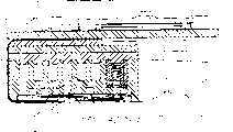
图7为图4~6中打印头组件剖面端部的立面图,它带有取自于打印头中心的剖面图。Figure 7 is an elevational view of the end section of the printhead assembly of Figures 4-6, with a section view taken through the center of the printhead.
图8为图4~6中打印头组件剖面端部的示意立面图,它取自于靠近图4的左端。8 is a schematic elevational view of the end section of the printhead assembly of FIGS. 4-6, taken near the left end of FIG. 4. FIG.
图9A为安装打印头分层堆栈结构打印芯片和喷嘴保护装置时的示意性端部立面图。FIG. 9A is a schematic end elevational view of installing the printing head layered stack structure to print chips and the nozzle protection device.
图9B为放大的图9A端部立面图的剖视图。Figure 9B is an enlarged cross-sectional view of the end elevation view of Figure 9A.
图10为打印头防护罩组件的分解透视图。Figure 10 is an exploded perspective view of the printhead shield assembly.
图11为模制油墨分配装置的示意性透视图。Figure 11 is a schematic perspective view of a molded ink dispensing device.
图12为分解透视图,它指出了本发明形成部分分层式油墨分配结构时的各层。Figure 12 is an exploded perspective view illustrating the layers of the present invention when formed into a partially layered ink distribution structure.
图13为图9A和9B中所描述结构的顶部阶梯剖面图。Figure 13 is a cross-sectional view of the top step of the structure depicted in Figures 9A and 9B.
图14为图13中所描述结构的底部阶梯剖面图。FIG. 14 is a cross-sectional view of the bottom step of the structure depicted in FIG. 13 .
图15为第一层压层的示意性透视图。Fig. 15 is a schematic perspective view of a first laminate layer.
图16为第二层压层的示意性透视图。Figure 16 is a schematic perspective view of a second laminate layer.
图17为第三层压层的示意性透视图Figure 17 is a schematic perspective view of a third laminate layer
图18为第四层压层的示意性透视图。Figure 18 is a schematic perspective view of a fourth laminate layer.
图19为第五层压层的示意性透视图。Figure 19 is a schematic perspective view of a fifth laminate layer.
图20为模制气阀的透视图。Figure 20 is a perspective view of a molded air valve.
图21为压纸卷筒右手端部的后透视图。Figure 21 is a rear perspective view of the right hand end of the platen.
图22为压纸卷筒左手端部的后透视图。Figure 22 is a rear perspective view of the left hand end of the platen.
图23为压纸卷筒的分解图。Figure 23 is an exploded view of the platen.
图24为压纸卷筒的横断面视图。Figure 24 is a cross-sectional view of the platen.
图25为打印纸光学传感器装置的前透视图。Fig. 25 is a front perspective view of the printing paper optical sensor device.
图26为打印头组件和附着于蓄墨盒的油墨管路的示意性透视图。Figure 26 is a schematic perspective view of a printhead assembly and ink lines attached to an ink reservoir.
图27为图26的部分分解图。FIG. 27 is a partially exploded view of FIG. 26 .
具体实施方式Detailed ways
下面结合附图,对本发明的首选实施例详细加以阐述:Below in conjunction with accompanying drawing, preferred embodiment of the present invention is elaborated:
在图1~3中,已经采用示意图的方式对打印引擎部件的核心部件进行详细描述,同时还指出了本发明的分层式油墨分配结构可能所处的一般环境。该打印引擎部件包括一个由压制钢、铝、塑料或其他刚性材料制成的底盘10。该底盘10安装在打印机的机身内,并用来安装打印头组件11、进纸机构以及其他设置在打印机塑料外壳内部的相关构件。In Figures 1-3, the core components of the print engine components have been described in detail schematically, while also indicating the general environment in which the layered ink distribution structure of the present invention may be located. The print engine components include a
在一般条件下,底盘10可支持打印头组件11,这样油墨就可从中喷出、落在此时正输送到打印头底部的打印纸或其他打印介质上,然后在进纸机构的作用下使其通过出口槽19。该进纸机构包括:一个进纸辊12、进纸导辊13、一般如14所示的压纸卷筒、出口辊15以及针轮装置16,并且所有装置均通过步进电动机17进行驱动。这些进纸构件均安装在两支承模塑件18之间,而且这两个轴承模塑件的两端均分别依次与底盘10相连接。Under normal conditions, the
打印头组件11通过已安装在底盘10上的每个打印头垫片20也与底盘10相连接。这些垫片20模件可使打印头组件的长度增加到220mm,同时允许其在210mm宽打印纸任一侧进行清除。The
通常,打印头的结构在图4~8中示出。Generally, the structure of the print head is shown in FIGS. 4-8.
打印头组件11包括一块印刷电路板(PCB)21,在该电路板上已经配有各种电子构件,其中包括:一个64MB的DRAM22、一个PEC芯片23、一个QA芯片连接器24、一个微控制器25以及一个双马达驱动芯片26。通常,打印头长度为203mm,它有10个打印芯片27(图13),每个芯片一般为21mm长。这些打印芯片27均同打印头的纵轴成小角度排列(参见图12),同时各打印芯片之间存在略微搭接现象,这能够连续在矩阵全长间距之间传输油墨。从电子学角度来看,每个打印芯片27都与磁带自动粘合(TAB)薄膜28的一端相连接,而另一端则通过TAB薄膜垫圈29保持与印刷电路板21下表面的电接触。The
首选的打印芯片结构已由本发明申请者在美国专利号6044646批文中详细加以描述。每个这类打印芯片27的长度大约为21mm,宽度小于1mm,高大约0.3mm;而在其较低表面上均配有数千个微型电动机械系统喷墨喷嘴30,这在图9A和9B中已经以图解法的方式表示出来,通常这类喷嘴均安设在六根管线当中——每根管线针对一种将采用的油墨。为了允许留有更近的点间隙,每根喷嘴管可以遵循交错排列型式进行布置。六条相应的油墨通道31管线均贯穿于整个打印芯片的后部,以便将油墨送往每个喷嘴的后部。按照图9A所示,每个打印芯片均配有一个喷嘴保护装置43以便保护打印芯片表面上的这些微型喷嘴,同时该保护装置还具有一些与喷嘴30对准的微小气孔44;这样以较高速度从这些喷嘴中喷出的墨点通过这些微型气孔,堆积在正从压纸卷筒14通过的打印纸上。The preferred print chip configuration is described in detail in US Patent No. 6,044,646 issued by the applicant of the present invention. The length of each such printed
借助模制分配装置35和构成打印头组件11的一部分的分层堆栈36,油墨被喷到各打印芯片上。来自墨盒(参见图26和27)的油墨,通过单独墨水软管传递到与盖模塑件39铸成一体的单独墨水进口34,该盖模塑件可形成模制塑料分配装置35的一个盖子。然而,模制分配装置35则包括六条单独的纵向墨水管道40和一条空气管道41,它们均贯穿于整个矩阵长度。来自进口34的墨水经过单独逆流通道42被传送到每个墨水管道40当中,详情请参考图7。虽然本文对打印头共介绍了六条管道,但是还可提供更多数量的管道,这一点要特别注意。这六条管道均适用于能够打印出四色叠印(CMYK)以及红外线固着油墨和固定剂效果的打印机。Ink is ejected onto each print chip by means of a molded
空气流经空气进口47,可直接送到空气管道41,从而将空气提供给每个打印芯片27,有关这一点可参考图6、7、8、20和21在以后详细加以介绍。The air flows through the air inlet 47 and can be directly sent to the
一些可形成分层堆栈36的片状层均位于纵向延伸的堆栈凹槽45的内部,该凹槽是在模制分配装置35的下侧形成的。通常,这些片状层都是由微型模制塑料材料制成。在每个TAB薄膜凹槽46(参见图12)内部将会接收到从打印头PCB21的底层伸出、缠绕在模制分配装置35后部周围的TAB薄膜28,多个TAB薄膜槽46沿着分层堆栈36的层设置,所述槽容纳所述打印芯片27。另外,该TAB薄膜将通过印刷电路板21向受分层结构支持的各个打印芯片27分程传递电子信号。A number of sheet-like layers that form the layered stack 36 are located inside longitudinally extending stack recesses 45 formed in the underside of the molded
模制分配装置、分层堆栈36以及相关构件等均根据图7~19详细加以介绍。The molded dispensing device, layered stack 36 and associated components are described in detail with reference to Figures 7-19.
图10详细介绍了作为一个塑料模制物而制成的盖模塑件39,其中包括一些定位套管48,它们用来定位顶部打印头盖49。FIG. 10 details the
如图7所示,墨水输送口50可与一根墨水管道40(从左数第四根)相连,该管道向下通至六根低位墨水管道当中的一根,或者向下通至模制分配装置下侧的过渡管道51。所有墨水管道40均配有相应的输送口50,它们分别与过渡管道51相通。这些过渡管道51彼此平行,但是所成角度与相连的墨水管道40有关,因此它们与将在下文提到的分层堆栈36的第一层52的墨水孔连接在一起。As shown in Figure 7, the
第一层52包括二十四个单独墨孔53,它们都可用于十个打印芯片27当中的每一个。这也就是说,在提供十个此类打印芯片的情况下,第一层52就含有二百四十个墨孔53。另外,第一层52还包含一排横靠在一个纵向边缘上的气孔54。The
通常,在一个矩形矩阵中可形成每组二十四个墨孔53,该矩形矩阵与数排墨水孔对中。每排四个墨水孔与过渡管道51对准,同时还平行于每个打印芯片。Typically, each set of twenty-four
第一层52的下表面包括多个下侧凹槽55。每个凹槽55均与四墨孔53中最中心的两墨孔之一相通(按照横穿第一层52的方向加以考虑)。这也就是说,墨孔53a(图13)可向图14所示的右手凹槽55a提供油墨,而墨孔53b则会向图14所示的左手最下侧的凹槽55b提供油墨。The lower surface of the
第二层56包括一对插槽57,其中每个插槽可接收从第一层下侧凹槽55当中其中一个凹槽内射出的油墨。The
第二层56还包括一些墨孔53,它们已经与两个第一层52的外侧墨孔53对中。这也就是说,墨水可穿过第一层52的十六个外侧墨孔53,因为每个打印芯片可直接穿过正通过第二层56的相应墨孔53。The
在第二层56的下侧位置已经形成许多横向延伸的管道58,从而将正在流经墨孔53c和53d的墨水转送到中心区。这些管道均向外延伸,从而与一对已通过层压制件第三层60形成的插槽59对中。应当值得注意的是,层压制件第三层60包括四个与每个打印芯片相对应的插槽59,其中两个内部插槽已经与一对在第二层56中形成的插槽,而外部插槽存在于这两个内部插槽。A plurality of laterally extending
第三层60还包括一排气孔54,它们已与第一层52和第二层56中所提供的相应气孔矩阵54相互对中。The
第三层60只有八个与打印芯片相对应的墨孔53。这些最外侧墨孔53均与第一、二层内所提供的最外侧墨孔53对准。如图9A和9B所示,第三层60包括一个位于其外表面的横向延伸管道61,它与每个墨孔53相对应。这些管道61可将来自相应墨孔53的墨水输送到正好在插槽59对中位置的外侧。The
如图9A和9B所示,这样通过每个打印芯片27的上表面,分层堆栈36的顶部三层可用来将来自于模制分配装置更宽间隙墨水管道40的墨水(如图9B中虚线剖面线所示)疏导至与墨水通道31队中的各个插槽当中。As shown in FIGS. 9A and 9B , the top three layers of the layered stack 36 can then be used to channel ink from the wider
如图13所示,从顶部分层堆栈的角度来看,插槽57和59实际由离散的共线间隙插槽构成。As shown in Figure 13, from the perspective of the top layer stack,
分层堆栈36的第四层62包括由十个芯片插槽65构成的矩阵,每个插槽与各打印芯片27相互对接。The
第五层即最后一层64还包括一个与芯片和喷嘴保护装置43对接的芯片插槽65。The fifth and
TAB薄膜28夹在第四、五层62和64之间,其中一层或两层可配有凹槽46,以便容纳TAB薄膜28的厚度。
作为一种精密微型模件的分层堆栈装置是通过注入乙缩醛二乙醇(Acetal)型材料而制成。它可调节通过已经附着的TAB薄膜来调节打印芯片27的矩阵,同时还与上文所提到的盖模塑件39相匹配。The layered stack device as a precision micro-module is made by infusing acetal diethyl alcohol (Acetal) type material. It accommodates the matrix of printed
当加强筋零件粘合在一起时,在微型模塑件下侧的加强筋可提供对TAB薄膜的支持。TAB薄膜可形成打印头模块的下侧墙壁,因为在加强筋间距之间存在足够的结构完整性,以便对弹性薄膜提供支持。TAB薄膜的各边缘均在盖模塑件39的底部墙壁上进行密封。如果最终的墨水输送到打印喷嘴上时,那么要把芯片粘贴到可在微型模件长度上运行的100微米宽的加强筋上。The ribs on the underside of the micromolding provide support for the TAB film when the ribbed parts are bonded together. The TAB film can form the underside walls of the printhead module because there is sufficient structural integrity between the rib spacing to provide support for the elastic film. The edges of the TAB film are sealed on the bottom wall of the
在对微型模件进行设计时可考虑在打印芯片对接成一排时对其进行物理搭接。因为此时各打印头芯片已形成一个连续的带状物(具有较大的容差),所以采用数字计算的方法对其进行调节以生成一个近似于完美的印刷模式,而非依靠非常接近规定公差的模件和异物来起到相同的作用。通常,模块间距为20.33mm。The design of the micromodule allows for physical bonding of the printed chips when they are butted together in a row. Because at this point the printhead chips have formed a continuous strip (with large tolerances), it is digitally adjusted to produce a near-perfect print pattern, rather than relying on very close to the specified Tolerance modules and foreign objects serve the same purpose. Typically, the module pitch is 20.33mm.
为了提供一个密封装置,可对分层堆栈和盖模塑件39的各层以及铸模分配装置进行粘合或以其他方式粘合在一起。各墨水通路可通过粘性透明塑料薄膜进行密封,以便指明何时墨水存在于该通路中,这样当顶部粘性薄膜被折叠时这些墨水通路可完全被覆盖。这时,墨水填充过程完成。The layers of the layered stack and cover
如图9b和13所示,分层堆栈36的上部四层52、56、60和62已经与气孔54对准,该气孔与作为在第四层62下表面形成的通道的空气管路63相通。在打印机处于操作模式时,这些通道可向打印芯片表面与喷嘴保护装置之间的间隙提供增压空气。来自该增压区的空气穿过喷嘴保护装置中的微型气孔44,这样可有效防止任何灰尘或不必要污染物在这些气孔处出现堆积。此外,为了在打印机不使用过程中有效防止墨水在喷嘴表面出现干燥现象,可关断增压空气供给装置,同时也可通过如图6、7、8、20和21中所示的气阀装置来控制气源装置。As shown in Figures 9b and 13, the upper four
参考图6~8,在打印头空气管道41中存在着一个铸模的气阀66,它是按照其底部带有一系列孔67的通道来形成的。这些孔的间距对应于在空气管道41(参见图6)中所形成的空气通道68,同时铸模气阀作为可在空气管道内纵向移动的部件;这样气孔67可被调节成与通道68对中的位置,以便通过分层堆栈装置向位于打印芯片和喷嘴保护装置之间的气孔提供增压空气,或者移出对中位置以关闭该气源装置。有些压缩弹簧69可通过空气管道41的底板保持与铸模气阀66底部的密封咬合状态,从而当关闭气阀时防止出现泄漏。Referring to Figures 6-8, in the
铸模气阀66具有一个一端向外延伸的凸轮随动件70,该随动件可与压纸卷筒14端盖74上的气阀凸轮面71相啮合,因而可根据多功能压纸卷筒14的旋转位置在空气管道41内有选择地纵向移动铸模气阀,该卷筒可根据打印机的运行状态在打印、加盖和吸墨等位置处进行旋转,其他情况可参考图21~24在下文中详细加以阐述。当压纸卷筒14处于打印旋转位置时,凸轮使气阀固定在其开启位置,从而可向打印芯片表面供气;然而当卷筒旋转到非打印位置,即:覆盖住喷嘴保护装置的微型气孔时,凸轮使铸模气阀移向阀门关闭位置。The molded
参考图纸21~24,压纸卷筒14在受到就位于支承模塑件18上旋转轴73的支持作用以及受到齿轮装置79(参见图3)的旋转作用下,可沿平行于打印头方向向外延伸。该旋转轴配有位于右手端的端盖74和一左手侧的端盖75,同时还配有两凸轮76和77。Referring to
压纸卷筒14具有卷筒表面78、加盖部分80和可沿其长度外伸的外露吸墨部分81,这三部分彼此之间按120度间隔开。在打印过程中,可旋转压纸卷筒组件,这样卷筒表面78可定位于正对打印头的位置,从而使卷筒表面对部分此时正在印刷的纸张起到支持的作用。当打印机处于闲置状态时,压纸卷筒组件发生转动,这样加盖部分80与打印头的底部发生接触,同时对微型气孔44周围的区域进行密封。结合在压纸卷筒14处于其加盖位置时通过气阀装置来关闭气阀,这便能够保持在打印喷嘴表面位置的密封气压。此外,这也能起到降低墨水溶剂(通常为水)的蒸发量,从而当打印机处于闲置时可减少墨水在各打印喷嘴上的烘干量。
旋转式压纸卷筒组件的第三个功能是用作吸墨纸,以便吸收当打印机启动或维修操作时来自于打印喷嘴的启动喷墨墨水。在打印机的这种模式下,压纸卷筒14旋转,使得外露吸墨部分81就位于对立于喷嘴保护装置43的墨水喷射通路。该外露吸墨部分81是压纸卷筒14内部的吸墨材料体82的外露部分,所以在外露吸墨部分81上所接收到的墨水被吸到压纸卷筒组件体之内。A third function of the rotating platen assembly is to act as a blotter to absorb the priming ink from the print nozzles during printer startup or maintenance operations. In this mode of the printer, the
有关压纸卷筒组件结构的其他详情可参见图23和24。通常,压纸卷筒组件由挤压或模制空心压纸卷筒体83构成,该压纸卷筒体不仅可构成压纸卷筒表面78,同时还能容纳成形的吸墨材料体82,其中从压纸卷筒体的纵向插槽伸出的部分形成外露吸墨部分81。压纸卷筒体83的扁平部件84可用作附着加盖部分80的一个底座,该加盖部分由盖外壳85、盖密封件86以及用于接触喷嘴保护装置43的泡沫件87等几部分构成。See Figures 23 and 24 for additional details regarding the structure of the platen assembly. Typically, the platen assembly consists of an extruded or molded
根据图1所示,每个支承模塑件18跨接于一对竖直轨道101。这也就是说,加盖装置要安装在四个允许其垂直移动的竖直轨道101上。在加盖装置任何一端下部的弹簧102可使加盖装置偏移进入到上升位置,同时保持凸轮76和77与打印头垫片20密切接触。According to FIG. 1 , each
当打印头组件11闲置不用时,可通过使用合成橡胶密封件86(或类似产品)来使全宽度加盖部分80覆盖打印头。为了旋转压纸卷筒14组件,可反转主辊驱动马达。这将使换向齿轮与压纸卷筒装置端部的齿轮79发生接触,并且将其旋转进入到自身三个功能位置(各相差120度)中的任何一个位置上。When the
位于压纸卷筒端盖74和75上的凸轮76和77可与各打印头垫片20上突起部分100咬合,从而有效控制压纸卷筒组件与打印头之间的间隙,这取决于压纸卷筒组件的旋转位置。这样,在转换压纸卷筒位置过程中,为了提供距离打印头更大的间隙,可以使压纸卷筒朝远离打印头的方向移动,同时也可以移回到适当距离以便使其分别起到支撑纸张、加盖以及吸墨等功能。
另外,通过轻微旋转压纸卷筒14即可使旋转式压纸卷筒的凸轮装置提供一种用于细调卷筒表面与打印机喷嘴之间距离的机构。这允许根据纸张厚度光学传感器装置(图25所示)探测到的纸张或其他正在印刷材料的厚度做出反应,以补偿喷嘴与压纸卷筒之间的间距。Additionally, the cam arrangement of the rotary platen, which can be rotated slightly by rotating the
该纸张厚度光学传感器包括一个光学传感器88和一个传感器挡光板装置:前者安装在PCB 21的下表面上;而后者安装在从分配模塑件突出的臂89上。传感器挡光板装置包括一个安装在轴91上的传感器挡光板构件90,转矩弹簧92使该轴偏转。当纸张进入到输纸辊上时,挡光板构件的最低部分接触纸张,同时朝弹簧92偏压相反方向旋转,旋转的量取决于纸张的厚度。这时,光学传感器探测挡光板构件的这一移动,并且PCB通过使压纸卷筒14进行补偿转动而响应所探测到的纸张厚度,以便优化纸张表面与喷嘴间的距离。The paper thickness optical sensor comprises an
图26和27示出了所述的打印头组件至可更换的墨盒93的连接。通过从一排位于打印机机架内侧带有内螺纹的墨阀95导出的软管94,向打印头输入六种不同颜色的墨水。将含有一个六间隔墨水气囊和相应阳螺纹阀门矩阵的可更换式墨盒93插入到打印机中,并和阀门95相匹配。该墨盒还包含一个进气口96和空气过滤器(未指出),并与吸气口连接器97相匹配,该连接器位于墨阀附近并导入向打印头提供过滤空气的气泵98中。同时,在墨盒内还包括一个QA芯片。当插入墨盒来与PCB上QA芯片连接器24建立起联系时,此QA芯片将与位于墨阀95与打印机吸气口连接器97间的触点99相连接。26 and 27 illustrate the connection of the printhead assembly to the
Claims (7)
Applications Claiming Priority (1)
| Application Number | Priority Date | Filing Date | Title |
|---|---|---|---|
| PCT/AU2000/000598WO2001089837A1 (en) | 2000-05-23 | 2000-05-24 | Paper thickness sensor in a printer |
Related Child Applications (1)
| Application Number | Title | Priority Date | Filing Date |
|---|---|---|---|
| CN 200510071908DivisionCN1689812B (en) | 2000-05-24 | 2000-05-24 | Method for distributing ink and air into a printing chip |
Publications (2)
| Publication Number | Publication Date |
|---|---|
| CN1452551A CN1452551A (en) | 2003-10-29 |
| CN1210154Ctrue CN1210154C (en) | 2005-07-13 |
Family
ID=3700817
Family Applications (1)
| Application Number | Title | Priority Date | Filing Date |
|---|---|---|---|
| CNB008195811AExpired - Fee RelatedCN1210154C (en) | 2000-05-24 | 2000-05-24 | Printer with adjustable distance between print head and printing surface and its adjustment method |
Country Status (9)
| Country | Link |
|---|---|
| US (8) | US7210867B1 (en) |
| EP (1) | EP1289762B1 (en) |
| JP (1) | JP2003534166A (en) |
| CN (1) | CN1210154C (en) |
| AT (1) | ATE309102T1 (en) |
| AU (2) | AU2000247332B2 (en) |
| DE (1) | DE60023952T2 (en) |
| WO (1) | WO2001089837A1 (en) |
| ZA (1) | ZA200209798B (en) |
Families Citing this family (27)
| Publication number | Priority date | Publication date | Assignee | Title |
|---|---|---|---|---|
| US7213989B2 (en)* | 2000-05-23 | 2007-05-08 | Silverbrook Research Pty Ltd | Ink distribution structure for a printhead |
| US6786658B2 (en)* | 2000-05-23 | 2004-09-07 | Silverbrook Research Pty. Ltd. | Printer for accommodating varying page thicknesses |
| US6526658B1 (en) | 2000-05-23 | 2003-03-04 | Silverbrook Research Pty Ltd | Method of manufacture of an ink jet printhead having a moving nozzle with an externally arranged actuator |
| US7004652B2 (en)* | 2000-05-23 | 2006-02-28 | Silverbrook Research Pty Ltd | Printer for accommodating varying page thickness |
| CN1210154C (en)* | 2000-05-24 | 2005-07-13 | 西尔弗布鲁克研究有限公司 | Printer with adjustable distance between print head and printing surface and its adjustment method |
| US7334876B2 (en)* | 2002-11-23 | 2008-02-26 | Silverbrook Research Pty Ltd | Printhead heaters with small surface area |
| US6755509B2 (en) | 2002-11-23 | 2004-06-29 | Silverbrook Research Pty Ltd | Thermal ink jet printhead with suspended beam heater |
| US7581822B2 (en)* | 2002-11-23 | 2009-09-01 | Silverbrook Research Pty Ltd | Inkjet printhead with low voltage ink vaporizing heaters |
| GB0327609D0 (en)* | 2003-11-27 | 2003-12-31 | Esselte B V B A | A method and apparatus adjusting the position of a printhead |
| JP2005169744A (en)* | 2003-12-09 | 2005-06-30 | Seiko Epson Corp | Recording apparatus and liquid ejecting apparatus |
| US7954737B2 (en) | 2007-10-04 | 2011-06-07 | Fellowes, Inc. | Shredder thickness with anti-jitter feature |
| US7631822B2 (en)* | 2004-09-10 | 2009-12-15 | Fellowes Inc. | Shredder with thickness detector |
| US8870106B2 (en)* | 2004-09-10 | 2014-10-28 | Fellowes, Inc. | Shredder with thickness detector |
| JP4508937B2 (en)* | 2005-05-12 | 2010-07-21 | キヤノン株式会社 | Recording device |
| US8672247B2 (en) | 2005-07-11 | 2014-03-18 | Fellowes, Inc. | Shredder with thickness detector |
| EP2152125B1 (en)* | 2007-04-27 | 2014-12-10 | Swift Distribution, Inc. | Percussion instrument support apparatus |
| GB2451513B (en) | 2007-08-02 | 2012-04-18 | Acco Uk Ltd | A shredding machine |
| US8430347B2 (en) | 2009-01-05 | 2013-04-30 | Fellowes, Inc. | Thickness adjusted motor controller |
| US8550387B2 (en)* | 2009-06-18 | 2013-10-08 | Tai Hoon K. Matlin | Restrictive throat mechanism for paper shredders |
| US8678305B2 (en)* | 2009-06-18 | 2014-03-25 | Fellowes, Inc. | Restrictive throat mechanism for paper shredders |
| US8382019B2 (en) | 2010-05-03 | 2013-02-26 | Fellowes, Inc. | In-rush current jam proof sensor control |
| US8511593B2 (en) | 2010-05-28 | 2013-08-20 | Fellowes, Inc. | Differential jam proof sensor for a shredder |
| US8451303B2 (en) | 2011-02-07 | 2013-05-28 | International Business Machines Corporation | Print media characterization |
| CN103786437A (en)* | 2012-12-30 | 2014-05-14 | 方正科技集团苏州制造有限公司 | Printer |
| US10377595B2 (en) | 2014-09-23 | 2019-08-13 | Hewlett-Packard Development Company, L.P. | Media flag |
| CN107316374B (en)* | 2017-06-13 | 2019-12-31 | 东方通信股份有限公司 | Magnetic detection mechanism for paper money |
| CN111145454B (en)* | 2020-03-03 | 2021-09-17 | 福建鼎煌自动化科技有限公司 | Ticket machine transmission system |
Family Cites Families (94)
| Publication number | Priority date | Publication date | Assignee | Title |
|---|---|---|---|---|
| US4417825A (en)* | 1981-03-03 | 1983-11-29 | Durango Systems, Inc. | Print drive medium for line/series printers |
| JPS57163588A (en)* | 1981-04-01 | 1982-10-07 | Mitsubishi Electric Corp | Printer |
| US4478146A (en)* | 1982-02-17 | 1984-10-23 | Monarch Marking Systems, Inc. | Ink roller support with pivotable cover |
| JPS60206657A (en)* | 1984-03-31 | 1985-10-18 | Canon Inc | Liquid jet recording head |
| EP0598701B1 (en)* | 1986-12-10 | 1998-03-25 | Canon Kabushiki Kaisha | Recording apparatus and discharge recovery method |
| CN1013840B (en)* | 1988-01-28 | 1991-09-11 | 精工爱普生株式会社 | Automatic Adjustment Mechanism for Platen Gap of Printer |
| JP3025778B2 (en)* | 1988-04-08 | 2000-03-27 | レックスマーク・インターナショナル・インコーポレーテッド | Printer with gap adjustment function of print head |
| US4893139A (en)* | 1989-02-10 | 1990-01-09 | Eastman Kodak Company | Compact camera providing direct and indirect flash |
| US5181050A (en)* | 1989-09-21 | 1993-01-19 | Rastergraphics, Inc. | Method of fabricating an integrated thick film electrostatic writing head incorporating in-line-resistors |
| JPH03169664A (en) | 1989-11-30 | 1991-07-23 | Ncr Corp | Bankbook printing machine |
| DE69027194T2 (en) | 1989-12-29 | 1996-10-17 | Canon Kk | Ink jet recorder |
| ES2048024B1 (en) | 1990-04-25 | 1995-02-16 | Fujitsu Ltd | PRINTING DEVICE PROVIDED WITH HEAD INTERVAL ADJUSTMENT DEVICE. |
| US5051761A (en)* | 1990-05-09 | 1991-09-24 | Xerox Corporation | Ink jet printer having a paper handling and maintenance station assembly |
| JP2840409B2 (en)* | 1990-08-24 | 1998-12-24 | キヤノン株式会社 | Ink jet recording head and ink jet recording apparatus |
| DE4041985A1 (en) | 1990-12-21 | 1992-07-02 | Mannesmann Ag | PRINTER, IN PARTICULAR MATRIX PRINTER |
| US5081472A (en)* | 1991-01-02 | 1992-01-14 | Xerox Corporation | Cleaning device for ink jet printhead nozzle faces |
| US5245356A (en)* | 1991-02-19 | 1993-09-14 | Rohm Co., Ltd. | Thermal printing head |
| US5108205A (en) | 1991-03-04 | 1992-04-28 | International Business Machines Corp. | Dual lever paper gap adjustment mechanism |
| EP0506403B1 (en)* | 1991-03-25 | 1995-08-23 | Tektronix, Inc. | Method and apparatus for providing phase change ink to an ink jet printer |
| US5160945A (en)* | 1991-05-10 | 1992-11-03 | Xerox Corporation | Pagewidth thermal ink jet printhead |
| US5541626A (en)* | 1992-02-26 | 1996-07-30 | Canon Kabushiki Kaisha | Recording apparatus and method for manufacturing recorded product thereby |
| US5594481A (en)* | 1992-04-02 | 1997-01-14 | Hewlett-Packard Company | Ink channel structure for inkjet printhead |
| US5648806A (en)* | 1992-04-02 | 1997-07-15 | Hewlett-Packard Company | Stable substrate structure for a wide swath nozzle array in a high resolution inkjet printer |
| JP3176130B2 (en)* | 1992-07-06 | 2001-06-11 | キヤノン株式会社 | Inkjet recording method |
| US5440332A (en)* | 1992-07-06 | 1995-08-08 | Compa Computer Corporation | Apparatus for page wide ink jet printing |
| US5309176A (en) | 1992-08-25 | 1994-05-03 | Sci Systems, Inc. | Airline ticket printer with stepper motor for selectively engaging print head and platen |
| US6050679A (en)* | 1992-08-27 | 2000-04-18 | Hitachi Koki Imaging Solutions, Inc. | Ink jet printer transducer array with stacked or single flat plate element |
| US5366301A (en) | 1993-12-14 | 1994-11-22 | Hewlett-Packard Company | Record media gap adjustment system for use in printers |
| US5565900A (en)* | 1994-02-04 | 1996-10-15 | Hewlett-Packard Company | Unit print head assembly for ink-jet printing |
| US5665249A (en)* | 1994-10-17 | 1997-09-09 | Xerox Corporation | Micro-electromechanical die module with planarized thick film layer |
| US5570959A (en) | 1994-10-28 | 1996-11-05 | Fujitsu Limited | Method and system for printing gap adjustment |
| DE69514675T2 (en)* | 1994-10-28 | 2000-10-26 | Rohm Co. Ltd., Kyoto | INK JET HEAD AND NOZZLE PLATE THEREFOR |
| US6012799A (en)* | 1995-04-12 | 2000-01-11 | Eastman Kodak Company | Multicolor, drop on demand, liquid ink printer with monolithic print head |
| AU712741B2 (en)* | 1995-04-26 | 1999-11-18 | Canon Kabushiki Kaisha | Liquid ejecting head, liquid ejecting device and liquid ejecting method |
| JPH08324065A (en)* | 1995-05-31 | 1996-12-10 | Tec Corp | Head gap adjusting device of printer |
| DE19522593C2 (en)* | 1995-06-19 | 1999-06-10 | Francotyp Postalia Gmbh | Device for keeping the nozzles of an ink print head clean |
| KR100208924B1 (en)* | 1995-08-22 | 1999-07-15 | 야스카와 히데아키 | Inkjet head connection unit, inkjet cartridge and assembly method thereof |
| JP3452111B2 (en)* | 1995-11-10 | 2003-09-29 | セイコーエプソン株式会社 | Ink jet recording head |
| JPH09286148A (en)* | 1996-04-24 | 1997-11-04 | Tec Corp | Printer |
| US5850246A (en)* | 1996-04-30 | 1998-12-15 | Eastman Kodak Company | Thermal printer with improved print head assembly |
| US6102509A (en) | 1996-05-30 | 2000-08-15 | Hewlett-Packard Company | Adaptive method for handling inkjet printing media |
| KR100186611B1 (en) | 1996-06-26 | 1999-05-15 | 김광호 | Paper thickness sensing device of image recording apparatus and recording head auto-controlling apparatus of inkjet recording apparatus and method thereof |
| US5757398A (en)* | 1996-07-01 | 1998-05-26 | Xerox Corporation | Liquid ink printer including a maintenance system |
| JPH1044418A (en)* | 1996-07-31 | 1998-02-17 | Canon Inc | Ink jet recording head and ink jet recording apparatus using the head |
| JP3114014B2 (en)* | 1997-06-10 | 2000-12-04 | セイコーインスツルメンツ株式会社 | Printer, print system, and print method using printer paper coated with photosensitive microcapsules |
| DE19726971C1 (en)* | 1997-06-25 | 1998-12-17 | Siemens Nixdorf Inf Syst | Inkjet printer with a nozzle cover and cleaning device |
| US7011390B2 (en)* | 1997-07-15 | 2006-03-14 | Silverbrook Research Pty Ltd | Printing mechanism having wide format printing zone |
| AUPO794697A0 (en) | 1997-07-15 | 1997-08-07 | Silverbrook Research Pty Ltd | A device (MEMS10) |
| US6788336B1 (en)* | 1997-07-15 | 2004-09-07 | Silverbrook Research Pty Ltd | Digital camera with integral color printer and modular replaceable print roll |
| US7551201B2 (en)* | 1997-07-15 | 2009-06-23 | Silverbrook Research Pty Ltd | Image capture and processing device for a print on demand digital camera system |
| US7195339B2 (en)* | 1997-07-15 | 2007-03-27 | Silverbrook Research Pty Ltd | Ink jet nozzle assembly with a thermal bend actuator |
| US6250738B1 (en)* | 1997-10-28 | 2001-06-26 | Hewlett-Packard Company | Inkjet printing apparatus with ink manifold |
| US6123410A (en)* | 1997-10-28 | 2000-09-26 | Hewlett-Packard Company | Scalable wide-array inkjet printhead and method for fabricating same |
| US6113232A (en) | 1997-12-19 | 2000-09-05 | Hewlett-Packard Company | Stationary pen printer |
| US6234605B1 (en)* | 1998-01-08 | 2001-05-22 | Xerox Corporation | Multiple resolution pagewidth ink jet printer including a positionable pagewidth printbear |
| US6196662B1 (en)* | 1998-03-02 | 2001-03-06 | Accent Color Sciences, Inc. | Method to utilize a fixed element print head to print various dot spacings |
| JPH11348373A (en)* | 1998-06-10 | 1999-12-21 | Ricoh Co Ltd | Ink jet recording device |
| EP0968825B1 (en)* | 1998-06-30 | 2005-09-14 | Canon Kabushiki Kaisha | Line head for ink-jet printer |
| US6259808B1 (en) | 1998-08-07 | 2001-07-10 | Axiohm Transaction Solutions, Inc. | Thermal transfer MICR printer |
| US6123260A (en) | 1998-09-17 | 2000-09-26 | Axiohm Transaction Solutions, Inc. | Flagging unverified checks comprising MICR indicia |
| US6196656B1 (en)* | 1998-10-27 | 2001-03-06 | Eastman Kodak Company | High frequency ultrasonic cleaning of ink jet printhead cartridges |
| US6357849B2 (en)* | 1998-11-12 | 2002-03-19 | Seiko Epson Corporation | Inkjet recording apparatus |
| DE69918937T2 (en)* | 1998-12-28 | 2005-07-28 | Fuji Photo Film Co., Ltd., Minami-Ashigara | Method and apparatus for imaging |
| US6386770B1 (en)* | 1999-01-07 | 2002-05-14 | Nec Corporation & Ntt Data Corporation | Printer |
| US6340225B1 (en)* | 1999-01-19 | 2002-01-22 | Xerox Corporation | Cross flow air system for ink jet printer |
| US6183063B1 (en)* | 1999-03-04 | 2001-02-06 | Lexmark International, Inc. | Angled printer cartridge |
| US6792146B2 (en)* | 1999-04-13 | 2004-09-14 | Qualcomm, Incorporated | Method and apparatus for entry of multi-stroke characters |
| DE19941871A1 (en)* | 1999-09-02 | 2001-04-19 | Hahn Schickard Ges | Apparatus and method for applying a plurality of microdroplets to a substrate |
| US6616271B2 (en) | 1999-10-19 | 2003-09-09 | Silverbrook Research Pty Ltd | Adhesive-based ink jet print head assembly |
| US6383274B1 (en)* | 1999-11-24 | 2002-05-07 | Xerox Corporation | Ink jet ink compositions and printing processes |
| US6398330B1 (en) | 2000-01-04 | 2002-06-04 | Hewlett-Packard Company | Apparatus for controlling pen-to-print medium spacing |
| US6585347B1 (en)* | 2000-01-31 | 2003-07-01 | Hewlett-Packard Company | Printhead servicing based on relocating stationary print cartridges away from print zone |
| US6318920B1 (en)* | 2000-05-23 | 2001-11-20 | Silverbrook Research Pty Ltd | Rotating platen member |
| US6409323B1 (en)* | 2000-05-23 | 2002-06-25 | Silverbrook Research Pty Ltd | Laminated ink distribution assembly for a printer |
| US6604810B1 (en)* | 2000-05-23 | 2003-08-12 | Silverbrook Research Pty Ltd | Printhead capping arrangement |
| US6281912B1 (en)* | 2000-05-23 | 2001-08-28 | Silverbrook Research Pty Ltd | Air supply arrangement for a printer |
| US6786658B2 (en)* | 2000-05-23 | 2004-09-07 | Silverbrook Research Pty. Ltd. | Printer for accommodating varying page thicknesses |
| US7004652B2 (en)* | 2000-05-23 | 2006-02-28 | Silverbrook Research Pty Ltd | Printer for accommodating varying page thickness |
| US7213989B2 (en)* | 2000-05-23 | 2007-05-08 | Silverbrook Research Pty Ltd | Ink distribution structure for a printhead |
| US6988840B2 (en)* | 2000-05-23 | 2006-01-24 | Silverbrook Research Pty Ltd | Printhead chassis assembly |
| US6652078B2 (en)* | 2000-05-23 | 2003-11-25 | Silverbrook Research Pty Ltd | Ink supply arrangement for a printer |
| US6488422B1 (en)* | 2000-05-23 | 2002-12-03 | Silverbrook Research Pty Ltd | Paper thickness sensor in a printer |
| CN1195634C (en)* | 2000-05-24 | 2005-04-06 | 西尔弗布鲁克研究有限公司 | Rotary Platen Parts |
| CN1210154C (en)* | 2000-05-24 | 2005-07-13 | 西尔弗布鲁克研究有限公司 | Printer with adjustable distance between print head and printing surface and its adjustment method |
| US6969144B2 (en)* | 2002-11-23 | 2005-11-29 | Silverbrook Research Pty Ltd | Printhead capping mechanism with rotary platen assembly |
| US6386670B1 (en)* | 2001-01-30 | 2002-05-14 | Lexmark International, Inc. | Printing black and three colors from three color data |
| JP3812823B2 (en)* | 2001-02-28 | 2006-08-23 | セイコーエプソン株式会社 | Printer control apparatus and printer control method |
| US20030099494A1 (en)* | 2001-11-28 | 2003-05-29 | Downing Steven P. | Apparatus and method for sensing media in a printing device |
| KR20030054157A (en)* | 2001-12-24 | 2003-07-02 | 엘지엔시스(주) | Sensing apparatus for thickness of transit body |
| JP4272381B2 (en)* | 2002-02-22 | 2009-06-03 | パナソニック株式会社 | Ink jet head and recording apparatus |
| US6740232B1 (en)* | 2002-05-01 | 2004-05-25 | Aquascape Designs, Inc. | Constructed wetlands system, treatment apparatus and method |
| US6869163B2 (en)* | 2002-05-21 | 2005-03-22 | Brother Kogyo Kabushiki Kaisha | Ink-jet recording apparatus |
| US6641251B1 (en)* | 2002-07-15 | 2003-11-04 | Hewlett-Packard Development Company, Lp. | Printing system for printing in scan and print media feed directions and method of performing a printing operation |
| US7213889B2 (en)* | 2005-01-04 | 2007-05-08 | Hung-Sheng Wang | Structure of a securing member of a wheel cover |
- 2000
- 2000-05-24CNCNB008195811Apatent/CN1210154C/ennot_activeExpired - Fee Related
- 2000-05-24AUAU2000247332Apatent/AU2000247332B2/ennot_activeCeased
- 2000-05-24JPJP2001586055Apatent/JP2003534166A/enactivePending
- 2000-05-24WOPCT/AU2000/000598patent/WO2001089837A1/enactiveIP Right Grant
- 2000-05-24DEDE60023952Tpatent/DE60023952T2/ennot_activeExpired - Lifetime
- 2000-05-24USUS10/296,524patent/US7210867B1/ennot_activeExpired - Fee Related
- 2000-05-24EPEP00929109Apatent/EP1289762B1/ennot_activeExpired - Lifetime
- 2000-05-24ATAT00929109Tpatent/ATE309102T1/ennot_activeIP Right Cessation
- 2002
- 2002-12-03ZAZA200209798Apatent/ZA200209798B/enunknown
- 2004
- 2004-07-15AUAU2004203239Apatent/AU2004203239B2/ennot_activeCeased
- 2007
- 2007-02-20USUS11/707,946patent/US7354208B2/ennot_activeExpired - Fee Related
- 2008
- 2008-02-25USUS12/036,910patent/US7517053B2/ennot_activeExpired - Fee Related
- 2009
- 2009-04-13USUS12/422,952patent/US7954928B2/ennot_activeExpired - Fee Related
- 2010
- 2010-11-16USUS12/947,618patent/US20110057989A1/ennot_activeAbandoned
- 2010-11-16USUS12/947,630patent/US20110063363A1/ennot_activeAbandoned
- 2010-11-16USUS12/947,650patent/US20110063365A1/ennot_activeAbandoned
- 2010-11-16USUS12/947,644patent/US20110063364A1/ennot_activeAbandoned
Also Published As
| Publication number | Publication date |
|---|---|
| JP2003534166A (en) | 2003-11-18 |
| ZA200209798B (en) | 2003-06-11 |
| DE60023952D1 (en) | 2005-12-15 |
| CN1452551A (en) | 2003-10-29 |
| EP1289762A1 (en) | 2003-03-12 |
| AU2004203239A1 (en) | 2004-08-12 |
| AU2000247332B2 (en) | 2004-04-22 |
| US20110063364A1 (en) | 2011-03-17 |
| US7210867B1 (en) | 2007-05-01 |
| WO2001089837A9 (en) | 2003-10-30 |
| US20110063363A1 (en) | 2011-03-17 |
| EP1289762B1 (en) | 2005-11-09 |
| US20090195624A1 (en) | 2009-08-06 |
| US20110057989A1 (en) | 2011-03-10 |
| AU2004203239B2 (en) | 2005-07-28 |
| EP1289762A4 (en) | 2004-07-14 |
| US7954928B2 (en) | 2011-06-07 |
| DE60023952T2 (en) | 2006-12-07 |
| WO2001089837A1 (en) | 2001-11-29 |
| US7517053B2 (en) | 2009-04-14 |
| US20110063365A1 (en) | 2011-03-17 |
| US20070189825A1 (en) | 2007-08-16 |
| ATE309102T1 (en) | 2005-11-15 |
| US20080143777A1 (en) | 2008-06-19 |
| US7354208B2 (en) | 2008-04-08 |
Similar Documents
| Publication | Publication Date | Title |
|---|---|---|
| CN1210154C (en) | Printer with adjustable distance between print head and printing surface and its adjustment method | |
| CN1270898C (en) | Ink supply arrangement for a printer | |
| CN1452550A (en) | Rotary Platen Parts | |
| AU2000247329B2 (en) | Laminated ink distribution assembly for a printer | |
| US7455391B2 (en) | Printing assembly with micro-electromechanical nozzle arrangements and a convergent ink distribution assembly | |
| CN1205044C (en) | Air supply unit for printer | |
| US20140063143A1 (en) | Laminated ink supply structure mounted in ink distribution arrangement of an inkjet printer | |
| AU2000247329A1 (en) | Laminated ink distribution assembly for a printer | |
| CN1238195C (en) | Array of abutting print chips in a pagewidth printhead | |
| US20090033713A1 (en) | Method of operating inkjet printer | |
| AU2000247332A1 (en) | Paper thickness sensor in a printer | |
| US6969144B2 (en) | Printhead capping mechanism with rotary platen assembly | |
| CN1623784A (en) | Printhead assembly with ink distribution mechanism | |
| CN1689812A (en) | Layered Ink Distribution Assemblies for Printers | |
| AU2004220748B2 (en) | Pagewidth inkjet printer with an ink distribution assembly | |
| AU2005201831B2 (en) | Printhead assembly having ink distribution structures | |
| AU2004202971B1 (en) | Printhead with laminated ink distribution assembly | |
| AU2005200473B1 (en) | Printhead assembly having ink distribution structures |
Legal Events
| Date | Code | Title | Description |
|---|---|---|---|
| C06 | Publication | ||
| PB01 | Publication | ||
| C10 | Entry into substantive examination | ||
| SE01 | Entry into force of request for substantive examination | ||
| C14 | Grant of patent or utility model | ||
| GR01 | Patent grant | ||
| ASS | Succession or assignment of patent right | Owner name:ZAMTEC LTD. Free format text:FORMER OWNER: SILVERBROOK RESEARCH PTY. LTD. Effective date:20140326 | |
| C41 | Transfer of patent application or patent right or utility model | ||
| TR01 | Transfer of patent right | Effective date of registration:20140326 Address after:Dublin, Ireland Patentee after:Silverbrook Research Pty Ltd. Address before:New South Wales, Australia Patentee before:Silverbrook Research Pty. Ltd. | |
| C56 | Change in the name or address of the patentee | Owner name:MAGTE TECHNOLOGY CO., LTD. Free format text:FORMER NAME: ZAMTEC LTD. | |
| CP01 | Change in the name or title of a patent holder | Address after:Dublin, Ireland Patentee after:MEMJET TECHNOLOGY LTD. Address before:Dublin, Ireland Patentee before:Silverbrook Research Pty Ltd. | |
| CF01 | Termination of patent right due to non-payment of annual fee | Granted publication date:20050713 Termination date:20170524 | |
| CF01 | Termination of patent right due to non-payment of annual fee |