CN1206657A - Paper Pressure Controllers for Printing Machines - Google Patents
Paper Pressure Controllers for Printing MachinesDownload PDFInfo
- Publication number
- CN1206657A CN1206657ACN98115640ACN98115640ACN1206657ACN 1206657 ACN1206657 ACN 1206657ACN 98115640 ACN98115640 ACN 98115640ACN 98115640 ACN98115640 ACN 98115640ACN 1206657 ACN1206657 ACN 1206657A
- Authority
- CN
- China
- Prior art keywords
- pressure
- paper
- roller
- guide
- moving member
- Prior art date
- Legal status (The legal status is an assumption and is not a legal conclusion. Google has not performed a legal analysis and makes no representation as to the accuracy of the status listed.)
- Granted
Links
Images


Classifications
- B—PERFORMING OPERATIONS; TRANSPORTING
- B41—PRINTING; LINING MACHINES; TYPEWRITERS; STAMPS
- B41J—TYPEWRITERS; SELECTIVE PRINTING MECHANISMS, i.e. MECHANISMS PRINTING OTHERWISE THAN FROM A FORME; CORRECTION OF TYPOGRAPHICAL ERRORS
- B41J2/00—Typewriters or selective printing mechanisms characterised by the printing or marking process for which they are designed
- B41J2/435—Typewriters or selective printing mechanisms characterised by the printing or marking process for which they are designed characterised by selective application of radiation to a printing material or impression-transfer material
- G—PHYSICS
- G03—PHOTOGRAPHY; CINEMATOGRAPHY; ANALOGOUS TECHNIQUES USING WAVES OTHER THAN OPTICAL WAVES; ELECTROGRAPHY; HOLOGRAPHY
- G03G—ELECTROGRAPHY; ELECTROPHOTOGRAPHY; MAGNETOGRAPHY
- G03G15/00—Apparatus for electrographic processes using a charge pattern
- G03G15/14—Apparatus for electrographic processes using a charge pattern for transferring a pattern to a second base
- G03G15/16—Apparatus for electrographic processes using a charge pattern for transferring a pattern to a second base of a toner pattern, e.g. a powder pattern, e.g. magnetic transfer
- G03G15/1665—Apparatus for electrographic processes using a charge pattern for transferring a pattern to a second base of a toner pattern, e.g. a powder pattern, e.g. magnetic transfer by introducing the second base in the nip formed by the recording member and at least one transfer member, e.g. in combination with bias or heat
- G03G15/167—Apparatus for electrographic processes using a charge pattern for transferring a pattern to a second base of a toner pattern, e.g. a powder pattern, e.g. magnetic transfer by introducing the second base in the nip formed by the recording member and at least one transfer member, e.g. in combination with bias or heat at least one of the recording member or the transfer member being rotatable during the transfer
- G—PHYSICS
- G03—PHOTOGRAPHY; CINEMATOGRAPHY; ANALOGOUS TECHNIQUES USING WAVES OTHER THAN OPTICAL WAVES; ELECTROGRAPHY; HOLOGRAPHY
- G03G—ELECTROGRAPHY; ELECTROPHOTOGRAPHY; MAGNETOGRAPHY
- G03G15/00—Apparatus for electrographic processes using a charge pattern
- G—PHYSICS
- G03—PHOTOGRAPHY; CINEMATOGRAPHY; ANALOGOUS TECHNIQUES USING WAVES OTHER THAN OPTICAL WAVES; ELECTROGRAPHY; HOLOGRAPHY
- G03G—ELECTROGRAPHY; ELECTROPHOTOGRAPHY; MAGNETOGRAPHY
- G03G2215/00—Apparatus for electrophotographic processes
- G03G2215/00362—Apparatus for electrophotographic processes relating to the copy medium handling
- G03G2215/00535—Stable handling of copy medium
- G03G2215/00717—Detection of physical properties
- G03G2215/00738—Detection of physical properties of sheet thickness or rigidity
- G—PHYSICS
- G03—PHOTOGRAPHY; CINEMATOGRAPHY; ANALOGOUS TECHNIQUES USING WAVES OTHER THAN OPTICAL WAVES; ELECTROGRAPHY; HOLOGRAPHY
- G03G—ELECTROGRAPHY; ELECTROPHOTOGRAPHY; MAGNETOGRAPHY
- G03G2215/00—Apparatus for electrophotographic processes
- G03G2215/16—Transferring device, details
- G03G2215/1604—Main transfer electrode
- G03G2215/1614—Transfer roll
Landscapes
- Physics & Mathematics (AREA)
- General Physics & Mathematics (AREA)
- Electrostatic Charge, Transfer And Separation In Electrography (AREA)
- Fixing For Electrophotography (AREA)
- Handling Of Continuous Sheets Of Paper (AREA)
Abstract
Translated fromChineseDescription
Translated fromChinese本发明涉及一种印制机,特别是一种印制机的纸压力控制器,其中转印辊与压辊之间的间隙可以根据印制纸张的厚度来控制。The invention relates to a printing machine, especially a paper pressure controller of the printing machine, wherein the gap between the transfer roller and the pressure roller can be controlled according to the thickness of the printed paper.
通常,激光印制机在用显影剂将感光带上的潜影显影后通过将显影图像转印在纸张上而印制出图像。Generally, a laser printer prints an image by transferring the developed image onto paper after developing the latent image on the photosensitive belt with a developer.
图1示出传统激光印制机。参照图1,感光带12由辊11a、11b、11c支承并环绕辊11a、11b、11c循环。静电潜影由激光扫描单元13形成在感光带12上并由显影装置14显影。此处,激光扫描单元13根据要印制的图像用光束扫描感光带12,显影装置14供应感光带12相应的显影剂。在彩色印制机中,彩色印制机对应于各种颜色,如黄(Y)、深红(M)、蓝绿(C)和黑(B),设有多个显影装置14和激光扫描单元13。Figure 1 shows a conventional laser printer. Referring to FIG. 1, a
接着,在感光带12的显影图像转印到转印辊15之后,转印图像印制在转印辊15和压辊18之间供应的纸张上。Next, after the developed image of the
压辊18通过固定在支承物19b上的弹簧19a以恒定压力弹性压着转印辊15。因此,恒定压力施加在转印辊15和压辊18之间从导向辊16供应的纸张。The
然而,在传统印制机中,压辊18受到弹簧19a的恒定压力而没有考虑到供应的纸张的厚度。因此,当纸张17很厚时,压辊18的压力通过转印辊15转移到感光带12上,则显影图像可能会扭曲。However, in the conventional printing machine, the
为解决上述问题,本发明的目的是提供一种印制机的纸压力控制器,其中,根据供应的纸张的厚度可以控制压在转印辊和压辊之间供应的纸张上的压力。To solve the above problems, an object of the present invention is to provide a paper pressure controller of a printing machine in which the pressure on the paper supplied between the transfer roller and the pressure roller can be controlled according to the thickness of the supplied paper.
相应地,为达到上述目的,提供了一种印制机的纸压力控制器,包括:压辊,设置以接触转印辊并在其与转印辊间供应有纸张;导向辊,用于在转印辊和压辊之间供应纸张,其特征在于,纸压力控制器包括:压力检测单元,用于根据导向辊之间供应的纸张的厚度变化来检测压力的变化;及压力改变单元,用于通过使压辊相对于转印辊垂直移动而控制压纸张的压辊的压力。Correspondingly, in order to achieve the above object, a paper pressure controller of a printing machine is provided, comprising: a pressure roller, arranged to contact a transfer roller and supply paper between it and the transfer roller; a guide roller, used for The paper is supplied between the transfer roller and the press roller, wherein the paper pressure controller includes: a pressure detection unit for detecting a change in pressure according to a change in thickness of the paper supplied between the guide rollers; and a pressure changing unit for Used to control the pressure of the pressure roller that presses the paper by moving the pressure roller vertically relative to the transfer roller.
压力改变单元包括:第一导向件,用于导引相对于转印辊垂直移动的压辊;移动件,其通过支承弹簧连接压辊;驱动装置,用于垂直移动移动件而使压辊相对于转印辊垂直移动;及第二导向件,用于导引垂直移动的移动件。The pressure changing unit includes: a first guide for guiding a pressure roller that moves vertically relative to the transfer roller; a moving member that connects the pressure roller through a support spring; a driving device for vertically moving the moving member so that the pressure roller is opposite The transfer roller moves vertically; and the second guide part is used to guide the moving part moving vertically.
驱动装置包括:滑块,用于在与移动件接触并水平移动时垂直移动移动件;导向支架,用于导引滑块;凸轮,用于在与滑块接触并旋转时水平移动滑块;及弹簧,用于将滑块压向凸轮。The driving device includes: a slider for vertically moving the moving member when in contact with the moving member and moving horizontally; a guide bracket for guiding the slider; a cam for horizontally moving the slider when in contact with the slider and rotating; and a spring to press the slider against the cam.
此处,滑块具有接触移动件的斜的下表面,并且移动件随着滑块水平移动而垂直移动。Here, the slider has an inclined lower surface contacting the moving member, and the moving member moves vertically as the slider moves horizontally.
本发明的上述目的及优点将通过参照附图详细地描述本发明的优选实施例而更加清楚,其中:The above objects and advantages of the present invention will be more clear by describing the preferred embodiments of the present invention in detail with reference to the accompanying drawings, wherein:
图1为说明传统印制机结构的示意图;Figure 1 is a schematic diagram illustrating the structure of a conventional printing machine;
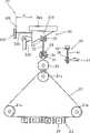
图2为采用本发明的纸压力控制器的印制机的结构的示意图;Fig. 2 is the schematic diagram of the structure of the printing machine that adopts paper pressure controller of the present invention;
图3为示出图2局部的透视图;Figure 3 is a perspective view showing part of Figure 2;
图4为示出本发明的另一实施例的导向辊和厚度传感器的剖视图。4 is a sectional view showing a guide roller and a thickness sensor of another embodiment of the present invention.
图2和3示出采用本发明的压辊的纸压力控制器的印制机20。如图2所示,感光带22由辊21a、21b、21c支承并环绕辊21a、21b、21c循环。用于以光束扫描感光带22而在感光带22上形成静电潜影的激光扫描单元和用于向感光带22供应黄(Y)、深红(M)、蓝绿(C)和黑(B)显影剂的显影装置相隔开并沿感光带22的循环路径设置。Figures 2 and 3 show a
随着转印辊25旋转而接触感光带22的表面,转印辊25将用墨粉形成的显影图像转印在纸张27上。纸张27通过一对导向辊26向转印辊25和压辊28之间供应。As the
本发明的纸压力控制器包括与压辊28连接的压力改变单元30及与导向辊26连接的压力检测单元40。The paper pressure controller of the present invention includes a
压力改变单元30垂直移动压辊28,即朝向或远离转印辊25以控制在转印辊25和压辊28之间供应的纸张所受到的压力。The
压力改变单元30包括第一导向件34,用于导引压辊28的转轴31,从而使压辊28能相对于转印辊25垂直移动;移动件33,由支承弹簧32连接压辊28并且通过第二导向件35的导引而相对于压辊28移动很短的一段距离;及驱动装置300,用于垂直移动移动件33。这里,支承弹簧32用于维持压辊28和移动件33之间的距离,并起缓冲作用。The
驱动装置300包括滑块310,用于在水平移动而与移动件33接触时垂直移动移动件33;导向支架340,用于导引滑块310;凸轮330,用于在旋转而与滑块310接触时水平移动滑块310;及弹簧320,连接滑块310,用于将滑块310压向凸轮330。滑块310具有接触移动件33的斜的下表面,因此,移动件33随着滑块310水平移动而垂直移动。
此外,压力检测单元40安装在一个导向辊26上,用于根据在导向辊26之间供应的纸张27的厚度来检测压力变化。压力检测单元40包括弹簧41,其一端连接一个导向辊26的转轴;传感器42,连接弹簧41的另一端,用于根据纸张27厚度的变化检测压力的变化。此外,压力改变单元30和压力检测单元40连接到一个控制器(未示出)。In addition, a
参照图2和3,随着压辊28根据纸张27的厚度相对于转印辊25垂直移动,压辊28压纸张的压力可以得到适当的控制。2 and 3, as the
在不供应纸张27时,传感器42检测到的压力为P1,如果在导向辊26之间供应纸张,则弹簧受压,压纸张27的压力增加到P2。根据弹簧41的位移的压力变化由传感器42检测,对应于压力差P2-P1的信号输入控制器。When the
控制器根据输入信号驱动凸轮330,并移动滑块310。这时,滑块310的位移可以通过滑块310和支架400支架的距离如下列公式表达:The controller drives the
滑块位移=滑块移动前的距离D1-滑块移动后的距离D2
其中,P1为供应纸张之前的导向辊的压力,P2为供应纸张之后的导向辊的压力,k为弹性常数,f为移动件33的转换常量。移动件33的转换常量为移动件33的垂直位移与滑块310的水平位移的比值。Wherein, P1 is the pressure of the guide roller before paper supply, P2 is the pressure of the guide roller after paper supply, k is the elastic constant, and f is the conversion constant of the moving
此外,控制器测量纸张27从导向辊26向转印辊25和压辊28之间的位置移动所需的时间,并且根据所需的时间精确地控制纸张27进入转印辊25和压辊28之间的时间及偏心凸轮330驱动的时间。In addition, the controller measures the time required for the
当偏心凸轮330旋转时,与其接触的滑块310沿导向支架340水平移动。相应地,与滑块310的斜面接触的移动件33沿着第二导向件35垂直移动,以改变压辊28的压力。When the
当纸张27通过导向辊26时,压力从P2变为P1。变化的压力值由传感器42检测并输入控制器。随后,偏心凸轮33由控制器旋转,滑块310通过弹簧320的恢复力而回到初始的位置。As the
图4示出用于检测纸张厚度的传感器的另一实例。传感器400接触导向辊26,测量传感器400和导向辊26之间供应的纸张的厚度,并向控制器传送表示厚度的信号。控制器向压力改变单元30(参照图3)传送根据输入信号从表1的查阅表得到的对应纸张27厚度的位移值。因此,压辊26以合适的力压住纸张27。表1
在如上所述的本发明中,由于纸张所受的压力通过控制压辊的位置而得到控制,因而,转印辊和感光带可以顺滑地运转,印制的质量可以提高。In the present invention as described above, since the pressure on the paper is controlled by controlling the position of the pressing roller, the transfer roller and the photosensitive belt can run smoothly and the quality of printing can be improved.
尽管为了说明已经参照附图详细描述了本发明的一个特例,应该明白:本领域的技术人员在不脱离本发明的精神和范围的前提下可以进行各种变形和等效变换。因此,应该明白本发明只由所附权利要求书限定。Although a specific example of the present invention has been described in detail with reference to the accompanying drawings for illustration, it should be understood that various modifications and equivalents can be made by those skilled in the art without departing from the spirit and scope of the invention. Accordingly, it should be understood that the invention is to be limited only by the appended claims.
Claims (5)
Applications Claiming Priority (3)
| Application Number | Priority Date | Filing Date | Title |
|---|---|---|---|
| KR1019970036176AKR100230318B1 (en) | 1997-07-30 | 1997-07-30 | Pressure controlling apparatus for laser printer |
| KR36176/97 | 1997-07-30 | ||
| KR36176/1997 | 1997-07-30 |
Publications (2)
| Publication Number | Publication Date |
|---|---|
| CN1206657Atrue CN1206657A (en) | 1999-02-03 |
| CN1073941C CN1073941C (en) | 2001-10-31 |
Family
ID=19516288
Family Applications (1)
| Application Number | Title | Priority Date | Filing Date |
|---|---|---|---|
| CN98115640AExpired - Fee RelatedCN1073941C (en) | 1997-07-30 | 1998-07-02 | Paper pressure controller for printing machine |
Country Status (4)
| Country | Link |
|---|---|
| US (1) | US6002891A (en) |
| JP (1) | JP2950414B2 (en) |
| KR (1) | KR100230318B1 (en) |
| CN (1) | CN1073941C (en) |
Cited By (4)
| Publication number | Priority date | Publication date | Assignee | Title |
|---|---|---|---|---|
| CN104986574A (en)* | 2015-06-04 | 2015-10-21 | 合肥京东方光电科技有限公司 | Guiding device and conveying device |
| CN105173825A (en)* | 2015-09-29 | 2015-12-23 | 中材科技股份有限公司 | Automatic felt rolling mechanism used for high-speed mineral cotton felt rolling |
| CN107326717A (en)* | 2017-07-12 | 2017-11-07 | 郭磊 | It is a kind of to detect the paper machine of paper sheet thickness |
| CN116021898A (en)* | 2022-11-11 | 2023-04-28 | 重庆大学 | An Embedded Label Counting Positioning Sensor |
Families Citing this family (23)
| Publication number | Priority date | Publication date | Assignee | Title |
|---|---|---|---|---|
| KR100362373B1 (en)* | 1999-11-20 | 2002-11-23 | 삼성전자 주식회사 | Apparatus for printing image and method for controlling thereof. |
| JP2001175089A (en)* | 1999-12-14 | 2001-06-29 | Fuji Xerox Co Ltd | Toner image transfer device |
| US6652054B2 (en) | 2000-02-01 | 2003-11-25 | Aprion Digital Ltd. | Table and a motion unit for adjusting the height thereof |
| KR100350986B1 (en)* | 2000-02-21 | 2002-08-28 | 삼성전자 주식회사 | Printer and method of controlling the gap of fusing roller |
| US6389242B1 (en)* | 2000-09-15 | 2002-05-14 | Toshiba Tec Kabushiki Kaisha | Image forming apparatus and image forming method |
| ATE500969T1 (en)* | 2000-10-23 | 2011-03-15 | Hewlett Packard Ind Printing | DEVICE AND METHOD FOR PROTECTING PRINT HEADS |
| KR100470504B1 (en)* | 2001-06-21 | 2005-02-21 | 가부시키가이샤 리코 | Fixing apparatus and image forming apparatus |
| KR100485786B1 (en)* | 2002-01-29 | 2005-04-28 | 삼성전자주식회사 | Electrophotograpic printer and method for controlling thereof |
| US7594651B2 (en)* | 2003-06-03 | 2009-09-29 | Hewlett-Packard Development Company, L.P. | Media feed system and method |
| KR100555912B1 (en)* | 2003-06-04 | 2006-03-03 | 삼성전자주식회사 | Printing Device and Paper Pickup Method |
| US7065308B2 (en)* | 2003-11-24 | 2006-06-20 | Xerox Corporation | Transfer roll engagement method for minimizing media induced motion quality disturbances |
| JP4821473B2 (en)* | 2006-07-18 | 2011-11-24 | コニカミノルタビジネステクノロジーズ株式会社 | Image forming apparatus |
| US20080265499A1 (en)* | 2007-04-27 | 2008-10-30 | Kabushiki Kaisha Toshiba | Image forming apparatus |
| JP5090827B2 (en)* | 2007-09-03 | 2012-12-05 | 株式会社リコー | Image forming apparatus |
| JP5458704B2 (en)* | 2008-07-30 | 2014-04-02 | 株式会社リコー | Intermediate transfer apparatus, image forming apparatus, and secondary transfer method of image forming apparatus |
| US8126362B2 (en)* | 2008-09-17 | 2012-02-28 | Xerox Corporation | System and method for measuring media thickness with a transfer subsystem in a printer |
| US8422925B2 (en)* | 2009-03-17 | 2013-04-16 | Ricoh Company, Ltd. | Transfer-fixing device and image forming apparatus incorporating same |
| US20100310292A1 (en)* | 2009-06-03 | 2010-12-09 | Kabushiki Kaisha Toshiba | Method and apparatus for forming image |
| US8606128B2 (en)* | 2010-05-11 | 2013-12-10 | Kabushiki Kaisha Toshiba | Image forming apparatus and method of controlling image forming apparatus for more efficient printing |
| JP6189027B2 (en)* | 2012-10-19 | 2017-08-30 | 桂川電機株式会社 | Contact / separation mechanism |
| JP6203566B2 (en)* | 2013-08-06 | 2017-09-27 | 常陽工学株式会社 | SEALING DEVICE AND SEALING METHOD |
| US10146165B2 (en)* | 2016-10-11 | 2018-12-04 | Canon Kabushiki Kaisha | Image forming apparatus |
| US10120317B2 (en)* | 2016-10-11 | 2018-11-06 | Canon Kabushiki Kaisha | Image forming apparatus |
Family Cites Families (8)
| Publication number | Priority date | Publication date | Assignee | Title |
|---|---|---|---|---|
| JPS5823052A (en)* | 1981-08-03 | 1983-02-10 | Fuji Xerox Co Ltd | Position adjusting device for corotron |
| JP2689469B2 (en)* | 1988-04-08 | 1997-12-10 | セイコーエプソン株式会社 | Printer paper feed mechanism |
| DE69109881T2 (en)* | 1990-01-30 | 1995-12-07 | Canon Kk | Sheet feeding device. |
| JPH05246562A (en)* | 1992-03-05 | 1993-09-24 | Murata Mach Ltd | Paper sheet feeding device |
| JP2837583B2 (en)* | 1992-07-06 | 1998-12-16 | シャープ株式会社 | Transfer device |
| JP3436331B2 (en)* | 1995-01-20 | 2003-08-11 | 株式会社リコー | Wet image forming apparatus and wet image forming method |
| JPH0934281A (en)* | 1995-07-21 | 1997-02-07 | Hitachi Ltd | Electrophotographic equipment |
| US5835832A (en)* | 1997-06-26 | 1998-11-10 | Eastman Kodak Company | Optimal toner charge for use with a compliant transfer intermediate |
- 1997
- 1997-07-30KRKR1019970036176Apatent/KR100230318B1/ennot_activeExpired - Fee Related
- 1998
- 1998-06-05JPJP10157704Apatent/JP2950414B2/ennot_activeExpired - Fee Related
- 1998-07-02CNCN98115640Apatent/CN1073941C/ennot_activeExpired - Fee Related
- 1998-07-15USUS09/115,512patent/US6002891A/ennot_activeExpired - Fee Related
Cited By (6)
| Publication number | Priority date | Publication date | Assignee | Title |
|---|---|---|---|---|
| CN104986574A (en)* | 2015-06-04 | 2015-10-21 | 合肥京东方光电科技有限公司 | Guiding device and conveying device |
| CN105173825A (en)* | 2015-09-29 | 2015-12-23 | 中材科技股份有限公司 | Automatic felt rolling mechanism used for high-speed mineral cotton felt rolling |
| CN105173825B (en)* | 2015-09-29 | 2017-09-12 | 中材科技股份有限公司 | A kind of automation Juan Zhan mechanisms for high speed mineral lap felt |
| CN107326717A (en)* | 2017-07-12 | 2017-11-07 | 郭磊 | It is a kind of to detect the paper machine of paper sheet thickness |
| CN107326717B (en)* | 2017-07-12 | 2019-05-28 | 东莞福迈包装印刷有限公司 | A kind of paper machine can detecte paper sheet thickness |
| CN116021898A (en)* | 2022-11-11 | 2023-04-28 | 重庆大学 | An Embedded Label Counting Positioning Sensor |
Also Published As
| Publication number | Publication date |
|---|---|
| KR19990012699A (en) | 1999-02-25 |
| JP2950414B2 (en) | 1999-09-20 |
| JPH1152744A (en) | 1999-02-26 |
| US6002891A (en) | 1999-12-14 |
| CN1073941C (en) | 2001-10-31 |
| KR100230318B1 (en) | 1999-11-15 |
Similar Documents
| Publication | Publication Date | Title |
|---|---|---|
| CN1206657A (en) | Paper Pressure Controllers for Printing Machines | |
| CN1109276C (en) | Laser printer | |
| US7758044B2 (en) | Image forming apparatus, sheet conveying device, and sheet conveying method | |
| EP1707391B1 (en) | Image recording device | |
| EP1705140B1 (en) | Recording apparatus with a two-way conveying means and a skew correction means | |
| EP1462264A1 (en) | Ink-jet line printer and image forming device using it | |
| US7591467B2 (en) | Sheet detecting device for image recording apparatus | |
| US7549635B2 (en) | Paper conveyance apparatus and image recording apparatus | |
| US20080122890A1 (en) | Image forming method and apparatus capable for preventing cockling | |
| US6343203B1 (en) | Image banding reduction method of photoreceptor medium of indirect transfer type image forming apparatus | |
| CN1121482A (en) | Sheet supply apparatus | |
| CN102442055B (en) | The method of imaging system and registering images | |
| US20090122096A1 (en) | Image forming apparatus with leading-edge detection sensor | |
| US8070250B2 (en) | Image forming apparatus | |
| KR20070015092A (en) | System and method for optically detecting a medium feeding failure in an image forming apparatus | |
| US10584008B2 (en) | Sheet conveying device and image forming apparatus incorporating the sheet conveying device | |
| CN1096958C (en) | Roller separating apparatus for laser printer | |
| US20080285988A1 (en) | Image forming apparatus and recording-medium feeding method | |
| US20200247162A1 (en) | Image forming apparatus | |
| JPH07291497A (en) | Image recording device | |
| JP4300912B2 (en) | RECORDING MEDIUM CONVEYING DEVICE AND IMAGE RECORDING DEVICE | |
| JPH1191293A (en) | Plotter | |
| JP2813180B2 (en) | Paper scanning mechanism of image forming apparatus | |
| JP4214869B2 (en) | Sheet feeding device | |
| WO2022049749A1 (en) | Thermal printer |
Legal Events
| Date | Code | Title | Description |
|---|---|---|---|
| C10 | Entry into substantive examination | ||
| SE01 | Entry into force of request for substantive examination | ||
| C06 | Publication | ||
| PB01 | Publication | ||
| C14 | Grant of patent or utility model | ||
| GR01 | Patent grant | ||
| C17 | Cessation of patent right | ||
| CF01 | Termination of patent right due to non-payment of annual fee | Granted publication date:20011031 |