CN1203013C - Method and device for cutting breakable plane workpiece, particularly, plate glass product - Google Patents
Method and device for cutting breakable plane workpiece, particularly, plate glass productDownload PDFInfo
- Publication number
- CN1203013C CN1203013CCNB981094066ACN98109406ACN1203013CCN 1203013 CCN1203013 CCN 1203013CCN B981094066 ACNB981094066 ACN B981094066ACN 98109406 ACN98109406 ACN 98109406ACN 1203013 CCN1203013 CCN 1203013C
- Authority
- CN
- China
- Prior art keywords
- thermal radiation
- cut
- hot spot
- rule
- shaped
- Prior art date
- Legal status (The legal status is an assumption and is not a legal conclusion. Google has not performed a legal analysis and makes no representation as to the accuracy of the status listed.)
- Expired - Fee Related
Links
- 238000000034methodMethods0.000titleclaimsabstractdescription39
- 238000005520cutting processMethods0.000titleclaimsdescription60
- 239000005357flat glassSubstances0.000titleclaimsdescription4
- 230000005855radiationEffects0.000claimsabstractdescription139
- 230000007246mechanismEffects0.000claimsabstractdescription35
- 239000000463materialSubstances0.000claimsabstractdescription15
- 238000002844meltingMethods0.000claimsabstractdescription13
- 230000008018meltingEffects0.000claimsabstractdescription13
- 238000001816coolingMethods0.000claimsdescription22
- 230000003287optical effectEffects0.000claimsdescription17
- 238000010438heat treatmentMethods0.000claimsdescription12
- 230000010355oscillationEffects0.000claimsdescription4
- 230000000694effectsEffects0.000claimsdescription2
- 239000002184metalSubstances0.000claimsdescription2
- 230000001276controlling effectEffects0.000claims4
- 230000008520organizationEffects0.000claims3
- 239000003034coal gasSubstances0.000claims1
- 238000001514detection methodMethods0.000claims1
- 230000011514reflexEffects0.000claims1
- 230000001105regulatory effectEffects0.000claims1
- 230000002787reinforcementEffects0.000claims1
- 239000011521glassSubstances0.000abstractdescription66
- 238000009826distributionMethods0.000abstractdescription10
- 238000012545processingMethods0.000abstractdescription3
- 230000035882stressEffects0.000description10
- 230000008569processEffects0.000description4
- 230000008859changeEffects0.000description3
- 230000007423decreaseEffects0.000description3
- 238000010586diagramMethods0.000description3
- 239000002245particleSubstances0.000description3
- 208000010392Bone FracturesDiseases0.000description2
- 206010017076FractureDiseases0.000description2
- 229910000831SteelInorganic materials0.000description2
- 238000010521absorption reactionMethods0.000description2
- 238000005336crackingMethods0.000description2
- 238000005516engineering processMethods0.000description2
- 239000007788liquidSubstances0.000description2
- 238000013021overheatingMethods0.000description2
- 238000007493shaping processMethods0.000description2
- 239000010959steelSubstances0.000description2
- 238000005452bendingMethods0.000description1
- 230000008901benefitEffects0.000description1
- 230000003247decreasing effectEffects0.000description1
- 238000011161developmentMethods0.000description1
- 229910003460diamondInorganic materials0.000description1
- 239000010432diamondSubstances0.000description1
- 238000004049embossingMethods0.000description1
- 239000000835fiberSubstances0.000description1
- 230000009477glass transitionEffects0.000description1
- 230000001678irradiating effectEffects0.000description1
- 238000003754machiningMethods0.000description1
- 238000004519manufacturing processMethods0.000description1
- 230000035515penetrationEffects0.000description1
- 239000000523sampleSubstances0.000description1
- 238000013077scoring methodMethods0.000description1
- 238000006748scratchingMethods0.000description1
- 230000002393scratching effectEffects0.000description1
- 230000035939shockEffects0.000description1
- 239000007921spraySubstances0.000description1
- 238000012360testing methodMethods0.000description1
- 230000008646thermal stressEffects0.000description1
- 238000009736wettingMethods0.000description1
Images


Classifications
- C—CHEMISTRY; METALLURGY
- C03—GLASS; MINERAL OR SLAG WOOL
- C03B—MANUFACTURE, SHAPING, OR SUPPLEMENTARY PROCESSES
- C03B33/00—Severing cooled glass
- C03B33/02—Cutting or splitting sheet glass or ribbons; Apparatus or machines therefor
- B—PERFORMING OPERATIONS; TRANSPORTING
- B23—MACHINE TOOLS; METAL-WORKING NOT OTHERWISE PROVIDED FOR
- B23K—SOLDERING OR UNSOLDERING; WELDING; CLADDING OR PLATING BY SOLDERING OR WELDING; CUTTING BY APPLYING HEAT LOCALLY, e.g. FLAME CUTTING; WORKING BY LASER BEAM
- B23K26/00—Working by laser beam, e.g. welding, cutting or boring
- B23K26/02—Positioning or observing the workpiece, e.g. with respect to the point of impact; Aligning, aiming or focusing the laser beam
- B23K26/06—Shaping the laser beam, e.g. by masks or multi-focusing
- B23K26/073—Shaping the laser spot
- B—PERFORMING OPERATIONS; TRANSPORTING
- B23—MACHINE TOOLS; METAL-WORKING NOT OTHERWISE PROVIDED FOR
- B23K—SOLDERING OR UNSOLDERING; WELDING; CLADDING OR PLATING BY SOLDERING OR WELDING; CUTTING BY APPLYING HEAT LOCALLY, e.g. FLAME CUTTING; WORKING BY LASER BEAM
- B23K26/00—Working by laser beam, e.g. welding, cutting or boring
- B23K26/08—Devices involving relative movement between laser beam and workpiece
- B23K26/082—Scanning systems, i.e. devices involving movement of the laser beam relative to the laser head
- B23K26/0821—Scanning systems, i.e. devices involving movement of the laser beam relative to the laser head using multifaceted mirrors, e.g. polygonal mirror
- B—PERFORMING OPERATIONS; TRANSPORTING
- B23—MACHINE TOOLS; METAL-WORKING NOT OTHERWISE PROVIDED FOR
- B23K—SOLDERING OR UNSOLDERING; WELDING; CLADDING OR PLATING BY SOLDERING OR WELDING; CUTTING BY APPLYING HEAT LOCALLY, e.g. FLAME CUTTING; WORKING BY LASER BEAM
- B23K26/00—Working by laser beam, e.g. welding, cutting or boring
- B23K26/36—Removing material
- B23K26/40—Removing material taking account of the properties of the material involved
- C—CHEMISTRY; METALLURGY
- C03—GLASS; MINERAL OR SLAG WOOL
- C03B—MANUFACTURE, SHAPING, OR SUPPLEMENTARY PROCESSES
- C03B33/00—Severing cooled glass
- C03B33/09—Severing cooled glass by thermal shock
- C03B33/091—Severing cooled glass by thermal shock using at least one focussed radiation beam, e.g. laser beam
- B—PERFORMING OPERATIONS; TRANSPORTING
- B23—MACHINE TOOLS; METAL-WORKING NOT OTHERWISE PROVIDED FOR
- B23K—SOLDERING OR UNSOLDERING; WELDING; CLADDING OR PLATING BY SOLDERING OR WELDING; CUTTING BY APPLYING HEAT LOCALLY, e.g. FLAME CUTTING; WORKING BY LASER BEAM
- B23K2103/00—Materials to be soldered, welded or cut
- B23K2103/50—Inorganic material, e.g. metals, not provided for in B23K2103/02 – B23K2103/26
- Y—GENERAL TAGGING OF NEW TECHNOLOGICAL DEVELOPMENTS; GENERAL TAGGING OF CROSS-SECTIONAL TECHNOLOGIES SPANNING OVER SEVERAL SECTIONS OF THE IPC; TECHNICAL SUBJECTS COVERED BY FORMER USPC CROSS-REFERENCE ART COLLECTIONS [XRACs] AND DIGESTS
- Y10—TECHNICAL SUBJECTS COVERED BY FORMER USPC
- Y10T—TECHNICAL SUBJECTS COVERED BY FORMER US CLASSIFICATION
- Y10T225/00—Severing by tearing or breaking
- Y10T225/10—Methods
- Y—GENERAL TAGGING OF NEW TECHNOLOGICAL DEVELOPMENTS; GENERAL TAGGING OF CROSS-SECTIONAL TECHNOLOGIES SPANNING OVER SEVERAL SECTIONS OF THE IPC; TECHNICAL SUBJECTS COVERED BY FORMER USPC CROSS-REFERENCE ART COLLECTIONS [XRACs] AND DIGESTS
- Y10—TECHNICAL SUBJECTS COVERED BY FORMER USPC
- Y10T—TECHNICAL SUBJECTS COVERED BY FORMER US CLASSIFICATION
- Y10T225/00—Severing by tearing or breaking
- Y10T225/30—Breaking or tearing apparatus
- Y10T225/304—Including means to apply thermal shock to work
Landscapes
- Physics & Mathematics (AREA)
- Optics & Photonics (AREA)
- Engineering & Computer Science (AREA)
- Plasma & Fusion (AREA)
- Mechanical Engineering (AREA)
- Chemical & Material Sciences (AREA)
- Materials Engineering (AREA)
- Organic Chemistry (AREA)
- Thermal Sciences (AREA)
- Toxicology (AREA)
- Health & Medical Sciences (AREA)
- Re-Forming, After-Treatment, Cutting And Transporting Of Glass Products (AREA)
- Laser Beam Processing (AREA)
- Perforating, Stamping-Out Or Severing By Means Other Than Cutting (AREA)
- Processing Of Stones Or Stones Resemblance Materials (AREA)
Abstract
Translated fromChineseDescription
Translated fromChinese技术领域technical field
本发明涉及一种用于分割易碎的平面工件且特别是平面玻璃制品的方法。本发明还涉及一种用于分割易碎的平面工件且特别是平面玻璃制品的装置。The invention relates to a method for dividing fragile planar workpieces, in particular planar glass products. The invention also relates to a device for dividing fragile planar workpieces, in particular planar glassware.
背景技术Background technique
平面玻璃的传统切割方法建立在这样的基础上,即首先用金刚石或切割刀在玻璃上产生划痕,以便随后用其它机械力沿如此形成的薄弱位置分割玻璃。在此方法中不利的是,颗粒(碎片)因刻痕而从表面脱落,这些颗粒可能堆积在玻璃上并例如在玻璃上造成刮伤。同样可能在切割边缘出现所谓的“断层浮凸”,这造成玻璃边缘不平整且进而需要高昂的后续加工成本。另外,在刻划时出现于切割边缘处的微裂缝造成了降低的机械应力强度即高断裂危险性。Conventional cutting methods for flat glass are based on first creating a scratch in the glass with a diamond or a cutting knife, in order to then use other mechanical forces to split the glass along the weak points thus created. A disadvantage of this method is that particles (shards) are detached from the surface by scoring, these particles can accumulate on the glass and cause scratches on the glass, for example. It is likewise possible for a so-called "fault relief" to occur at the cut edge, which results in uneven glass edges and thus requires high subsequent processing costs. In addition, microcracks that occur at the cut edges during scoring result in a reduced mechanical stress intensity, ie a high risk of fracture.
为了不仅避免碎片,也避免断层浮凸和微裂缝,开始在热生应力的基础上分割玻璃。在这种情况下,对准玻璃的热源在玻璃上方匀速通过并产生如此高的热应力以致玻璃开裂。所需的热源性能可以局部地即精确地而最好是毫米级地(这与标准切割精度是对应的)确定热能位置,红外线辐射器、专用的气焊枪和特别是激光器就足以。因其良好的聚焦性能、优良的功率控制性能以及射束成型性能和其在玻璃上的强度分布而选用激光器。In order to avoid not only splinters, but also fault embossing and micro-cracks, the glass began to be split on the basis of thermally induced stresses. In this case, a heat source directed at the glass passes over the glass at a constant velocity and creates such high thermal stress that the glass cracks. The required properties of the heat source can determine the location of the heat energy locally, ie precisely, preferably on the millimeter scale (this corresponds to the standard cutting precision). Infrared radiators, special gas torches and especially lasers are sufficient. The laser was chosen for its good focusing properties, excellent power control properties and beam shaping properties and its intensity distribution on the glass.
DE-AS1244346公开了一种玻璃刻划方法,其中用激光束沿切割轨迹加热玻璃并在这里设定了一个低于玻璃熔点温度的温度。在加热后冷却玻璃并通过敲击或弯曲方式分断玻璃。还可以进行熔点之上的加热,从而熔融出一条细缝。DE-AS 1244346 discloses a glass scoring method in which the glass is heated along the cutting path with a laser beam and a temperature below the melting temperature of the glass is set here. Cool the glass after heating and break it by hitting or bending. It is also possible to heat above the melting point to melt a thin seam.
GB-PS1433563描述了一种利用两束激光工作的方法。在这里,利用一束低能量激光进行预热。GB-PS1433563 describes a method of working with two laser beams. Here, it is preheated with a low-energy laser.
在DE4411037C2中描述了一种方法,其中借助激光束在空心玻璃中引入一个250℃的环形应力区。在引入应力区后,用划线针并通过与空心玻璃表面的短暂接触而以机械方式引入起始短裂缝,此裂缝基本上位于激光束最高强度的轨迹上并同时设定最高温度。借助液体浸润纤维冷却所述应力区,随后提高热突变和应力,从而使起始裂缝形成切割缝。DE 4411037 C2 describes a method in which an annular stress zone at 250° C. is introduced into the hollow glass by means of a laser beam. After the introduction of the stress zone, an initial short crack is introduced mechanically with a scribing needle and by brief contact with the hollow glass surface, which essentially lies on the trajectory of the highest intensity of the laser beam and at the same time sets the highest temperature. Cooling of the stress zone by means of liquid-wetting the fibers, followed by an increase in thermal shock and stress, causes the initial crack to form a kerf.
US5237150描述了一种厚钢板切割工艺。它采用环模式激光束来保护聚焦透镜。激光束在击中透镜时成环形,从而与点形撞击时的情况相比,激光束能量分布在一个更大的透镜表面上,由此避免了透镜材料局部过热。但激光束仍然借助聚焦镜在工件上会聚成一点。不象环形光斑时的那样,在此光斑点中不存在边缘区内的高强度,这是因为环形射束变成一个“点”,这个“点”作为“切割点”沿分割线切割钢板。US5237150 describes a thick steel plate cutting process. It uses a ring-mode laser beam to protect the focusing lens. When the laser beam hits the lens, it forms a ring, so that the energy of the laser beam is distributed over a larger lens surface than would be the case with a point-shaped impact, thereby avoiding local overheating of the lens material. However, the laser beam is still converged to a point on the workpiece by means of a focusing mirror. Unlike in the case of an annular spot, in this spot there is no high intensity in the edge region, because the annular beam becomes a "point" which cuts the steel plate along the parting line as a "cutting point".
在根据EP0062484所述的方法中,同样采用了TEM0环模式激光束。此激光束呈点状聚集在工件上。但如果激光束成点状聚焦时,则强度最大值合成一点。由于激光束聚焦在工件表面上,所以玻璃蒸发到一定深度。在分割区内的其余玻璃被一直加热到熔点温度以上。借助气体将经过蒸发的玻璃材料吹去。In the method according to EP0062484 a TEM0 ring mode laser beam is also used. This laser beam is focused on the workpiece in a point-like manner. However, if the laser beam is focused in a point shape, the maximum intensity will be integrated into one point. As the laser beam is focused on the workpiece surface, the glass is evaporated to a certain depth. The rest of the glass in the split zone is heated up to a temperature above the melting point. The evaporated glass material is blown away with the aid of gas.
DE-OS4305107涉及一种用激光束分割玻璃的方法和装置,其中激光束被分成两束平行射线并相对分割线对称地用这两束激光冲击玻璃。在这样的布局中,不可能形成准确的间距(±0.1mm),而是裂缝在两条射线之间摆动。DE-OS4305107 relates to a method and a device for splitting glass with a laser beam, wherein the laser beam is split into two parallel beams and the glass is hit with the two laser beams symmetrically with respect to the splitting line. In such a layout, it is not possible to form an exact pitch (±0.1mm), but instead the cracks swing between the two rays.
由WO93/20015公开的方法采用了椭圆形激光束。在沿直线切割非金属板材时,此方法显示了良好的效果,但是不能保证沿弯曲轮廓产生第一流的和最精确的刻痕。另外,在高射束密度和高速切割的情况下,此方法的切割过程不稳定性。还与此有关的是,利用横截面为椭圆形的高斯激光束加热实现了射束密度分布在一个很窄的区域内,其中温度从外周指向中央地递增。当随着工件加热而通常在辐射区的中央区内产生过热现象即超过材料软化温度的现象时,在高速和裂缝很深的情况下获得稳定的热裂且还要获得稳定的功率密度是很困难的,即使在第一流的切割过程中,这也是不允许的。The method disclosed by WO93/20015 employs an elliptical laser beam. This method has shown good results when cutting non-metallic sheet material along straight lines, but does not guarantee the first-rate and most accurate scoring along curved contours. In addition, in the case of high beam density and high cutting speed, the cutting process of this method is unstable. It is also relevant here that the heating with a Gaussian laser beam having an elliptical cross-section achieves a beam density distribution in a narrow region, with the temperature increasing from the periphery to the center. It is very difficult to obtain stable hot cracking at high speeds and deep cracks and also to obtain stable power densities when overheating, i.e. exceeding the softening temperature of the material, usually occurs in the central zone of the radiation zone as the workpiece is heated. Difficult, which is not allowed even in top-notch cutting.
作为最接近的现有技术WO96/20062描述了一种用相对分割线对称的热辐射光斑沿分割线切割易碎的平面工件且特别是平面玻璃制品的方法,所述热辐射光斑在最高温度位于其后端的边缘区内具有高辐射强度,其中热辐射光斑沿分割线和/或工件运动,加热的分割线段随后受到冷却。As the closest prior art, WO96/20062 describes a method of cutting fragile planar workpieces and especially planar glass products along the parting line with a thermal radiation spot symmetrical to the parting line at the highest temperature at It has a high radiation intensity in the edge region at its rear end, where the hot radiation spot moves along the parting line and/or the workpiece, the heated parting line segment is subsequently cooled.
在已知情况中,规定了椭圆形或蛋形热辐射光斑,其中在椭圆形内出现了最低辐射强度。这样的“切割光斑”两次切割分割线即在椭圆形前端和后端上切割分割线。由此有缺陷地产生了不利的温度分布(在WO文献的图1中示出了)。通过前行切割点已经发生了在椭圆形切割光斑的前区内且沿切割方向(见分割线区)的不必要加热。In known cases, an elliptical or egg-shaped heat radiation spot is specified, wherein the lowest radiation intensity occurs within the ellipse. Such a "cutting spot" cuts the dividing line twice, ie on the front and rear ends of the ellipse. This disadvantageously results in an unfavorable temperature distribution (shown in FIG. 1 of the WO document). Unnecessary heating in the front region of the elliptical cutting spot and in the cutting direction (see parting line region) has already occurred by the preceding cutting point.
因此,在切割光斑中央即分割线上出现了不必要的大量加热,从而玻璃或许已经在焦点端部熔化了。相反在分割线区域中的辐射强度在此焦点端部处很高且温度在此端达到最高值。As a result, an unnecessarily large amount of heating occurs in the center of the cutting spot, ie at the parting line, so that the glass may already melt at the ends of the focal point. In contrast, the radiation intensity in the region of the dividing line is high at the end of the focal point and the temperature reaches its highest value at this end.
另外,只能利用此方法切割厚度通常达0.2mm的玻璃,这是因为否则的话,在所需的高辐射功率情况下会发生熔化而中断刻痕。在玻璃较厚的情况下,只发生刻划玻璃。In addition, only glass with a thickness of typically up to 0.2 mm can be cut with this method, since otherwise melting would occur at the high radiation power required and the score would be interrupted. In the case of thicker glass, only scratching of the glass occurs.
发明内容Contents of the invention
本发明的任务是准备提供一种方法和装置,可以利用此方法和装置切割平面产品特别是较厚的产品如厚达0.2mm以上的玻璃片且不会出现微裂缝、断层浮凸或碎片。另外,在厚玻璃的情况下,获得了比可用其它方法获得的刻痕更深的刻痕。The object of the present invention is to provide a method and a device with which flat products, in particular thicker products such as glass sheets up to 0.2 mm thick, can be cut without micro-cracks, fault relief or chips. Also, in the case of thick glass, deeper scores are obtained than can be obtained with other methods.
本发明提供一种沿预定分割线切割易碎的平面工件、特别是平面玻璃制品的方法,其中利用相对分割线对称的热辐射光斑加热分割线,所述热辐射光斑在最高温度位于其后端的边缘区内具有高辐射强度,热辐射光斑沿分割线和/或工件移动,其中受热的分割线部分随后受到冷却,其特征在于,采用这样一种热辐射光斑,即其辐射强度高的光斑边缘区位于V形或U形曲线上,所述曲线向着热辐射光斑前端开口,其中局部地位于分割线上的V形或U形曲线最高点处的最高温度低于工件材料的熔点温度。The present invention provides a method for cutting a fragile planar workpiece, especially a planar glass product, along a predetermined parting line, wherein the parting line is heated by a heat radiation spot symmetrical to the parting line, and the heat radiation spot is located at its rear end with the highest temperature. High radiation intensity in the edge zone, the heat radiation spot moves along the parting line and/or the workpiece, wherein the heated part of the parting line is subsequently cooled, characterized in that a heat radiation spot is used with a high radiation intensity at the edge of the spot The zone is located on a V-shaped or U-shaped curve that opens toward the front of the heat radiation spot, wherein the highest temperature at the highest point of the V-shaped or U-shaped curve locally located on the dividing line is lower than the melting point temperature of the workpiece material.
通过上述的方法,首先在热处理快结束时在分割线上引入能量并由此获得了工件局部高温。于是,利用分割线上的局部最高温度产生一个高机械应力。当随后冷却分割线时和当先前在切割起点减弱玻璃强度时,玻璃沿送进方向在分割线上开裂。由于在分割线上局部增强了最高温度,所以在分割线后很精确地形成了切口,这例如在显示器制造工业中是必不可少的。With the method described above, energy is firstly introduced at the parting line towards the end of the heat treatment and thus a local high temperature of the workpiece is obtained. Thus, a high mechanical stress is generated by means of the local maximum temperature on the parting line. When the parting line is subsequently cooled and when the strength of the glass is previously weakened at the starting point of the cut, the glass is cracked at the parting line in the feeding direction. Due to the local increase of the maximum temperature at the parting line, the cutouts are formed very precisely behind the parting line, which is essential, for example, in the display manufacturing industry.
本发明方法的另一个优点在于,无需在加热和冷却处理后进行机械分断处理而获得了整齐的分割边。Another advantage of the method according to the invention is that clean cut edges are obtained without the need for a mechanical severing process after the heating and cooling process.
在根据本发明形成的U形或V形热辐射光斑的情况下,辐射强度高的热辐射光斑区位于V形或U形曲线上,此曲线在切割方向上开口。V形或U形曲线的两个支脚与分割线隔开相同距离,从而在这种热辐射光斑形状的情况下,通过两个隔开的最高强度且先在宽范围内(可达数毫米)加热工件表面,其中在这两个最高强度间出现了局部最低温度。由于V形或U形曲线的支脚在热辐射光斑后端会聚成最高点,所以局部最低温度逐渐降低,即分割线区域内的温度逐渐向热辐射光斑端部增高并在端部特别是在工件表面上达到局部最高温度,但此最高温度仍低于工件熔点温度。这种热辐射光斑的作用是:在最高强度的隔开区内,在宽范围内且在深度上将工件均匀加热到低于熔点的温度。当在最高强度位于中心的情况下辐射时、特别是在热辐射光斑开始时,上述情况是不同的。在如此形成的热痕后,紧接着用液体、气体或低温冷却的机械探测头进行冷却,所述冷却在分割线上具有最高强度。冷却造成材料收缩。由于在最高温度位于分割线上的较大宽度内加热,所以与同样在分割线上显示出最高强度的冷却一起产生了在分割线上具有增大的局部最高值的应力。由此完全可以切割较厚工件。试验证明了,可以稳定地切断厚度高达1.1mm的玻璃片。In the case of the U-shaped or V-shaped heat radiation spot formed according to the present invention, the heat radiation spot area with high radiation intensity is located on the V-shaped or U-shaped curve which opens in the cutting direction. The two legs of the V-shaped or U-shaped curve are separated by the same distance from the dividing line, so that in the case of this heat radiation spot shape, the two separated highest intensities and first in a wide range (up to several millimeters) The workpiece surface is heated, with a local minimum temperature occurring between these two maximum intensities. Since the feet of the V-shaped or U-shaped curve converge to the highest point at the rear end of the heat radiation spot, the local minimum temperature gradually decreases, that is, the temperature in the area of the dividing line gradually increases toward the end of the heat radiation spot and at the end, especially at the workpiece A local maximum temperature is reached on the surface, but this maximum temperature is still lower than the melting point temperature of the workpiece. The function of this thermal radiation spot is to uniformly heat the workpiece to a temperature below the melting point over a wide range and in depth in the isolated zone of highest intensity. This is different when irradiating with the highest intensity in the center, especially at the beginning of the thermal radiation spot. The heat trace thus formed is followed by cooling with liquid, gas or cryogenically cooled mechanical probe, said cooling having the highest intensity at the parting line. Cooling causes the material to shrink. As a result of the heating in the greater width where the highest temperature is located on the parting line, together with the cooling which also exhibits the highest intensity on the parting line, stresses with increased local maximums on the parting line result. This makes it possible to cut thicker workpieces completely. Tests have proven that glass sheets up to 1.1mm thick can be cut stably.
V形或U形热辐射光斑宽度优选为0.5mm-2mm。热辐射光斑长度可以为10mm-30mm。当调节上述宽度和长度时,根据在工件深度上的均匀加热等条件,考虑进给速率、工件厚度、辐射强度、材料性能。The width of the V-shaped or U-shaped thermal radiation spot is preferably 0.5mm-2mm. The heat radiation spot length can be 10mm-30mm. When adjusting the above-mentioned width and length, the feed rate, workpiece thickness, radiation intensity, material properties, etc. are considered according to conditions such as uniform heating over the depth of the workpiece.
根据一个优选实施例,热辐射光斑是由激光束扫描产生的。According to a preferred embodiment, the spot of thermal radiation is produced by scanning a laser beam.
扫描优选地以椭圆形方式进行,其中为了形成U形或V形曲线,交替地接通和关闭激光器或增强和减弱辐射强度。The scanning is preferably performed in an elliptical manner, wherein the laser is switched on and off or the radiation intensity is increased and decreased alternately in order to form a U-shaped or V-shaped curve.
根据一种沿预定分割线切割易碎的平面工件、特别是平面玻璃制品的装置,其中此装置具有:一个光学机构,为了产生一个相对分割线对称的热辐射光斑,此光学机构具有一个热辐射源特别是激光器和至少一个光学元件,所述热辐射光斑在其边缘区内具有高辐射强度且在其后端上具有最高温度;一个用于使待分割工件和/或热辐射光斑沿分割线移动的机构;一个用于冷却受到辐射的分割线段的冷却机构,上述任务是这样解决的,即,光学机构和/或热辐射源被设计用于产生热辐射光斑,所述热辐射光斑的高辐射强度边缘区位于V形或U形曲线上,所述曲线向着热辐射光斑前端开口,其中局部地位于分割线的V形或U形曲线的最高点处的最高温度低于工件材料的熔点温度。According to a device for cutting a fragile planar workpiece, in particular a planar glass product, along a predetermined parting line, wherein the device has: an optical mechanism, in order to generate a thermal radiation spot symmetrical to the parting line, the optical mechanism has a thermal radiation The source is in particular a laser and at least one optical element, the thermal radiation spot has a high radiation intensity in its edge region and the highest temperature on its rear end; Moving mechanism; a cooling mechanism for cooling the irradiated parting line segment, the above-mentioned task is solved in that the optical mechanism and/or the heat radiation source are designed to generate a heat radiation spot, the high temperature of the heat radiation spot The radiation intensity edge region is located on a V-shaped or U-shaped curve that opens toward the front of the heat radiation spot, wherein the highest temperature locally located at the highest point of the V-shaped or U-shaped curve of the dividing line is lower than the melting point temperature of the workpiece material .
根据第一实施例,采用了扫描器机构。与此相应的是,光学机构具有两个彼此垂直布置的协调摆动的反射镜,所述反射镜如此将激光束反射到工件表面,即,使它在工件表面上划出V形或U形曲线。According to the first embodiment, a scanner mechanism is employed. Correspondingly, the optics has two coordinated pivoting mirrors arranged perpendicular to one another, which reflect the laser beam onto the workpiece surface in such a way that it traces a V-shaped or U-shaped curve on the workpiece surface .
为了使这两个反射镜协调,这两个反射镜的驱动机构与一个公用控制调节机构相连。这两个反射镜的摆动频率优选为500Hz-2000Hz,从而可以达到50mm/s-1000mm/s的切割速率,这与所用的辐射强度有关。In order to coordinate the two mirrors, the drive mechanisms for the two mirrors are connected to a common control and adjustment mechanism. The oscillation frequency of the two mirrors is preferably 500Hz-2000Hz, so that a cutting rate of 50mm/s-1000mm/s can be achieved, which is related to the intensity of the radiation used.
根据另一个扫描器机构的实施例,光学机构具有镜轮,镜轮表面是如此弯曲的,即由所述表面反射的激光束在镜轮转动时在待分割工件表面上一次划出V形或U形曲线。According to another embodiment of the scanner mechanism, the optical mechanism has a mirror wheel whose surface is so curved that the laser beam reflected by said surface traces a V-shape or U-shaped curve.
镜轮转动频率为500Hz-3000Hz,从而可以达到上述进给速率。The rotation frequency of the mirror wheel is 500Hz-3000Hz, so that the above-mentioned feed rate can be achieved.
最好采用具有这样波长的激光器,即所述波长在材料中被大量吸收。例如,对于玻璃而言采用CO2激光器,此激光器具有10.6um的波长且利于较好地保持不变。激光器的最大输出功率通常为150瓦特。It is preferable to use a laser having a wavelength which is largely absorbed in the material. For example, for glass aCO2 laser is used, which has a wavelength of 10.6um and is good for invariance. The maximum output power of the laser is usually 150 watts.
激光强度在每次扫描V形或U形曲线时是变化的,从而V形或U形曲线可以在切割点区内改变辐射强度。最好如此调节辐射强度,即不超过工件的熔化温度。The laser intensity is varied each time the V-shaped or U-shaped curve is scanned, so that the V-shaped or U-shaped curve can change the radiation intensity in the cutting point area. Preferably, the radiation intensity is adjusted such that the melting temperature of the workpiece is not exceeded.
可以采用这样的扫描器运动控制机构,即当进行圆形切割和自由切割时,它控制扫描器以产生与曲线轨迹吻合的弯曲的V形或U形强度分布,就象以后还要根据图示详细描述的那样。Such a scanner motion control mechanism can be used, that is, when performing circular cutting and free cutting, it controls the scanner to produce a curved V-shaped or U-shaped intensity distribution that matches the curved trajectory, as shown in the diagram below as described in detail.
替代扫描器运动的是,也可以通过射束成型光学系统获得所希望的热辐射光斑形状。Instead of moving the scanner, the desired shape of the thermal radiation spot can also be achieved by means of beam-shaping optics.
另一种可能方式是,采用TEM01*激光式热辐射光斑,其中光学机构具有相应的遮光件,所述遮光件遮挡了部分光束,从而工件表面上的高辐射强度位于V形或U形曲线上。TEM01*式是由CO2激光器的特殊共振结构产生的。Another possibility is to use a TEM01* laser-type thermal radiation spot, where the optics has a corresponding shutter, which blocks part of the light beam, so that the high radiation intensity on the workpiece surface lies on a V- or U-shaped curve . The TEM01* formula is produced by the special resonance structure of theCO2 laser.
至于冷却机构,例如可以采用低温冷却的金属探测头。另外,还可以将煤气加热辐射机构、喷液机构或喷雾器用作冷却机构。As cooling means, for example a cryogenically cooled metal detector head can be used. In addition, gas heating radiant means, liquid spray means or atomizers can also be used as cooling means.
附图说明Description of drawings
以下将根据附图来进一步描述本发明例举出的实施方式,其中:The exemplary embodiments of the present invention will be further described below according to the accompanying drawings, wherein:
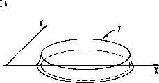
图1是分割工件的断面主视图。Fig. 1 is a sectional front view of a divided workpiece.
图2是热辐射光斑强度分布的三维视图。Fig. 2 is a three-dimensional view of the intensity distribution of thermal radiation spots.
图3是沿线A-A’、B-B’、C-C’且穿过图1所示热辐射光斑的强度截面或温度截面的截面图。Figure 3 is a cross-sectional view of the intensity profile or temperature profile along the lines A-A', B-B', C-C' and through the thermal radiation spot shown in Figure 1 .
图4是沿分割线的温度分布曲线图。Fig. 4 is a graph of temperature distribution along the dividing line.
图5是光学和冷却机构的透视图。Figure 5 is a perspective view of the optics and cooling mechanism.
图6是本发明装置的另一个实施例的透视图。Figure 6 is a perspective view of another embodiment of the device of the present invention.
图7a-c是带有强度截面的另一个本发明装置实施例的视图。Figures 7a-c are views of another embodiment of the device of the present invention with strength sections.
图8A-C示出了支脚延长到最高点上方的V形热辐射光斑以及所属温度分布。8A-C show a V-shaped heat radiation spot with legs extended above the highest point and the associated temperature distribution.
图9是包括所述控制机构在内的本发明装置的整体布局的示意框图,所述装置可以利用弯曲的热辐射光斑进行自由切割。Fig. 9 is a schematic block diagram of the overall layout of the device of the present invention including the control mechanism, and the device can use the curved heat radiation spot for free cutting.
图10示出了通过沿分割线的扫描而成的、紧邻带有对应于分割线曲率地呈V形或U形延伸的且包含所述曲率在内的弯曲的热辐射光斑的所引入的热辐射束的两维视图,所述热辐射光斑是由扫描器环形运动产生的。FIG. 10 shows the introduced thermal radiation spot by scanning along the dividing line next to a curved thermal radiation spot with a V-shaped or U-shaped extension corresponding to the curvature of the dividing line and including the curvature. A two-dimensional view of a radiation beam, the spot of thermal radiation produced by circular motion of the scanner.
图11示出了对应于图10的热辐射光斑,但此光斑是由扫描器往复运动产生的。Figure 11 shows a thermal radiation spot corresponding to Figure 10, but this spot is produced by the reciprocating motion of the scanner.
具体实施方式Detailed ways
在图1中示出了玻璃片1的主视图,所述玻璃片可以沿线2(分割线)分断开。一个成U形的热辐射光斑3对准玻璃片1(其沿箭头方向(进给方向)移动)的表面。高辐射强度区域由U形曲线4表示,所述曲线在进给方向上开口。热辐射光斑的形状约等于半个椭圆,所述椭圆的最宽区域构成了热辐射光斑3的前端。FIG. 1 shows a front view of a glass sheet 1 which can be severed along a line 2 (parting line). A U-shaped
U形曲线4的两个支脚18、19彼此隔开且相对分割线2是对称的。在热辐射光斑3前端区内,支脚18、19间距约为1mm。支脚18、19间距向着位于分割线2上的最高点16缩小。The two
在图2中,以三维视图画出了热辐射光斑3的强度分布。可以看到,最大强度的波峰线向最高点降低,与分割线2有关的局部最大值17位于最高点16处。辐射强度在热辐射光斑内明显较低。必须与工件厚度和切割速率对应地调节局部最大值17。在高速切割或高速进给的情况下,局部最大值17高于低速切割时的局部最大值。在这种情况下,也必须根据在曲线4前端区内的辐射强度值确定局部最大值。In FIG. 2 the intensity distribution of the
与分割线有关的局部最大值必须同时不是曲线最小值。例如,当不存在功率控制地使用激光器时,强度可以在最高点16处略高一些。Local maxima associated with dividing lines must also not be curve minima. For example, when the laser is used without power control, the intensity may be slightly higher at
在图3中画出了沿线A-A’、B-B’、C-C’的三张强度截面剖视图。可以看到,曲线变化(由截面图C-C’表示)具有两个明显高于在B-B’截面图中的两个隔开的最高点的隔开最高点。在由截面图A-A’表示的最高点16处,强度最大值还是明显较低。由于通过这两个最高点而在围绕分割线的宽范围内进行预热,所以与在分割线区域内的截面B-B’有关的温度轮廓只示出了较低的局部最小值。通过最高点处的较小强度来平衡此最小值,从而在最高点16处显示出最大值位于分割线2区内时的温度变化。最大值仍然低于玻璃熔点温度Tg。In Fig. 3 are drawn three strength cross-sectional views along the lines A-A', B-B', C-C'. It can be seen that the curve change (represented by cross-section C-C') has two spaced peaks that are significantly higher than the two spaced peaks in cross-section B-B'. At the
在图4中示出了包括冷却点5在内的沿分割线的温度变化情况。FIG. 4 shows the temperature profile along the dividing line including the
在图5中示出了在玻璃板1上产生热辐射光斑3的装置。在玻璃板1表面上示出了分割线2以及高强度的U形曲线4。作为热辐射源地采用了发射激光束7的激光器6、特别是CO2激光器。激光束7击中了绕垂直轴摆动的第一反射镜8,此反射镜使激光束7在平行于一个玻璃板1表面的平面内来回移动。摆动的激光束击中了绕水平轴摆动的第二反射镜9,此反射镜使反射激光束沿X方向来回移动。反射镜8、9的布局还可以互换。根据这两种摆动的叠加效果,激光束在工件表面上刻划出U形曲线4。为了使这两个反射镜8、9的摆动协调以获得U形曲线4,拟定了一种公用的控制调节机构11,它通过控制线路10a、10b与这两个反射镜8、9的未示出的驱动机构相连。A device for producing a
可以如此控制反射镜8、9,即激光束在工件上扫描出一条封闭曲线。为了保持U形或V形曲线形状,相应地接通和关闭激光器。The mirrors 8, 9 can be controlled in such a way that the laser beam scans a closed curve on the workpiece. To maintain the U-shaped or V-shaped curve shape, the laser is switched on and off accordingly.
在热辐射光斑3后面示出了冷却点5,此冷却点是通过由喷嘴12喷出的冷却气产生的。此喷嘴与气体供应机构13相连。Shown behind the
在图6中示出了工件1,具有三角形形状的热辐射光斑3对准此工件表面。高强度区由V形曲线4表示。此V形曲线也相对分割线对称布置,从而最高点16位于分割线2上。为了调节这样的V形曲线4,拟定了一种激光器6,它发射出击中镜轮14的激光束7。镜轮14表面15不是圆柱形的,而是设计成曲面形状,从而当镜轮14在工件表面上转动一次时,至少一次地扫描出V形曲线4。In FIG. 6 a workpiece 1 is shown, the surface of which a
在图7中草草地画出了这样一种布局,其中采用了激光器6,它产生TEM01*式激光束7。在激光器6和工件1之间设有挡住一半激光束7的遮光板20。在图7b、7c中相应地示出了在遮光板前和遮光板后的强度截面。Such an arrangement is schematically drawn in FIG. 7, in which a
由于可获得高机械应力,所以证明了此方法完全适用于切割厚达1.1mm的玻璃,而迄今尚不能证明利用如现有技术所述的方法进行这样的切割。在典型的50mm/s-500mm/s的进给速率下,所用的CO2激光器的功率为12瓦特-50瓦特。在宽度为1mm的情况下,热辐射光斑长度通常在进给方向上为12mm。切割边没有微裂纹、断层浮凸和碎片。在厚度达0.7mm以上的玻璃的情况下,近似垂直的深裂缝表现出深达数百微米的深度,这同样是不可能用上述其它方法实现的。Due to the high mechanical stresses achievable, this method has proven to be perfectly suitable for cutting glass up to a thickness of 1.1 mm, whereas such cutting has not been proven to date with methods as described in the prior art. The power of theCO2 laser used is 12 watts to 50 watts at a typical feed rate of 50mm/s-500mm/s. In the case of a width of 1 mm, the thermal radiation spot length is typically 12 mm in the feed direction. Cut edges are free from microcracks, fault relief and chips. In the case of glass with a thickness of more than 0.7 mm, approximately vertical deep cracks exhibit a depth of several hundreds of micrometers, which is likewise impossible to achieve with the other methods described above.
不应该教条地理解V形或U形的命名。在这里,也可以采用相近曲线如抛物线。在图6所示的V形光斑3情况下,支脚4不必必须终止于最高点。如图8所示,它可以具有一直延伸到最高点上方的支脚4。在分图8A中,V形支脚4和其延伸段4a一样长且形成了似X形的光斑。在分图8B中,延长的支脚4a比原来的V形支脚短。The V-shape or U-shape nomenclature should not be understood dogmatically. Here, an approximate curve such as a parabola can also be used. In the case of the V-shaped
究竟采用变型A或变型B,这取决于玻璃的材料特性参数。Whether variant A or variant B is used depends on the material property parameters of the glass.
通常,这些特性参数是热动态参数(导热性)、玻璃厚度、光学性能(吸收激光束)。因此简而言之,质量涉及以下结论:Typically, these characteristic parameters are thermodynamic parameters (thermal conductivity), glass thickness, optical properties (absorption of the laser beam). So in short, quality involves the following conclusions:
-导热性良好:支脚长度短,热量快速渗入玻璃中;- Good thermal conductivity: the short length of the legs allows the heat to penetrate quickly into the glass;
-厚度大:支脚长度长,热量需要散入玻璃中的时间。-Large thickness: the length of the legs is long, the time it takes for the heat to dissipate into the glass.
-吸收:支脚长度长,热量需要散入玻璃中的时间。-Absorption: The length of the legs gives the time it takes for the heat to dissipate into the glass.
原则上,图8B所示的光斑也可以两侧互换地变化(短侧在左)。In principle, the light spots shown in FIG. 8B can also be varied interchangeably on both sides (short side on the left).
在这些射束几何形状情况下,玻璃被快速加热即局部温度梯度很高,这可能导致玻璃损坏。由于热的玻璃渗热时间短,所以突然超过玻璃相变温度Tg。结果是,产生不受控制的断裂或玻璃表面颗粒的龟裂。With these beam geometries, the glass is heated rapidly, i.e. the local temperature gradient is high, which can lead to glass damage. Due to the short heat penetration time of hot glass, it suddenly exceeds the glass transition temperature Tg. The result is uncontrolled fracture or cracking of glass surface particles.
图8A所示的激光束光斑以及相似的图8B所示的光斑最好具有如图8C所示的、在点M具有最高温度的温度曲线和强度曲线。Preferably, the laser beam spot shown in FIG. 8A and similarly the spot shown in FIG. 8B has a temperature profile and an intensity profile with the highest temperature at point M as shown in FIG. 8C.
另外,激光束强度原则上具有在局部和时间上连续的高斯形状。如果在玻璃上使这两束激光在十字交叉点方向从A点移动到H点,则产生以下温度曲线:In addition, the laser beam intensity basically has a locally and temporally continuous Gaussian shape. If the two laser beams are moved on the glass from point A to point H in the direction of the cross point, the following temperature curve is produced:
A点:玻璃具有环境温度Point A: Glass has ambient temperature
M点:在A和M之间连续加热玻璃并在M点到达最高温度。此最高温度低于相变温度Tg。Point M: Continuously heat the glass between A and M and reach the highest temperature at point M. This maximum temperature is lower than the phase transition temperature Tg.
H点:在M和H之间保温或略微降温。在此阶段中,热量或多或少地从表面散入玻璃内部。通过有目的地在切割方向上或与之垂直的方向对温度梯度进行平整,所以明显改善了切割质量。Point H: keep warm or slightly cool down between M and H. During this phase, the heat is more or less dissipated from the surface into the interior of the glass. Due to the targeted leveling of the temperature gradient in the cutting direction or perpendicular thereto, the cutting quality is significantly improved.
如图所示,图8A和8B中的支脚4、4a优选为直线形状的。但它们原则上也可以是略微弯曲的。As shown, the
在用激光束切割玻璃时,热辐射光斑宽度通常明显小于其长度。此外,对可接受的切割来说重要的是,关于玻璃上表面,在切割区内的表面点必须接受一定时间的加热和冷却过程。结果,在加快切割的情况下,射束宽度的确保持不变,可是必须加长射束。另外,对设备切割能力很重要的高速切割需要沿分割线的窄长形热辐射光斑。热辐射束的典型长度为10mm-50mm、宽度为0.5mm-2mm,其趋势是高精度下的窄宽度。When cutting glass with a laser beam, the heat radiation spot width is usually significantly smaller than its length. Furthermore, it is important for an acceptable cut that, with respect to the upper surface of the glass, the surface points in the cutting zone must be subjected to a heating and cooling process for a certain period of time. As a result, in the case of faster cutting, the beam width does remain the same, but the beam must be lengthened. In addition, high-speed dicing, which is important to the cutting capability of the device, requires a narrow, elongated spot of heat radiation along the parting line. The typical length of the thermal radiation beam is 10mm-50mm, and the width is 0.5mm-2mm, and the trend is narrow width under high precision.
只要进行直线切割,利用延长的热辐射光斑进行切割就没有问题。Cutting with an extended thermal radiation spot is no problem as long as the cut is straight.
但在预定应用场合中,必须进行具有任意预定形状的切割。人们称这样的切割为“自由切割”或“外形切割”。But in the intended application, it is necessary to make a cut with any predetermined shape. People call such cuts "free cuts" or "contour cuts."
例如在将汽车玻璃切割成玻璃片或反射镜时以及为了在平面玻璃片中引入较大的孔时,采用这样的外形切割。Such profile cuts are used, for example, when cutting automotive glass into glass sheets or mirrors and to introduce larger holes in flat glass sheets.
需要特别考虑这种外形切割的过程。The process of cutting this profile requires special consideration.
在进行曲线切割时,热辐射束必须与弯曲断面的轨迹匹配,同时在待切割玻璃中产生一个最大机械应力并使线能量宽度窄。另外,在利用线性热辐射束的情况下,在利用延长的热辐射束进行曲线切割时只可获得短的切割弯曲半径。因此在曲线半径较长的情况下,只能利用较短的热辐射束进行加工。但后者只具有低的切割速率。When performing curved cuts, the thermal radiation beam must match the trajectory of the curved section while creating a maximum mechanical stress and narrow line energy width in the glass to be cut. In addition, in the case of linear heat radiation beams, only short cutting bend radii are achievable in curved cuts with elongated heat radiation beams. Therefore, in the case of longer curve radii, only shorter thermal radiation beams can be used for processing. But the latter has only a low cutting rate.
在已经提及的WO93/20015或WO96/20062中描述了一种用于形成延长的热辐射光斑以便切割玻璃的装置。在此装置中,热辐射束根据切割曲线的局部形状弯曲,从而产生了相对切割曲线的最小偏差。由于此装置仍是利用了只可有限度地改变热辐射束的固定光学元件进行加工,所以注定此装置在这里实际上只能进行圆形切割,这是因为此装置在这种情况下只能以不变的弯曲半径进行切割。In the already mentioned WO93/20015 or WO96/20062 a device for forming an elongated spot of thermal radiation for cutting glass is described. In this device, the thermal radiation beam is bent according to the local shape of the cutting curve, resulting in a minimum deviation from the cutting curve. Since this device is still processed with fixed optical elements that can only change the thermal radiation beam to a limited extent, it is doomed that this device can only perform circular cutting in practice here, because this device can only in this case Cuts with a constant bend radius.
虽然可以高速切割PKW玻璃以便制成反射镜或玻璃,但它在高速切割下需要在切割过程中改变射束形状,这在已知装置中是无法做到的。Although PKW glass can be cut at high speed to make mirrors or glass, it requires changing the beam shape during cutting at high speed, which cannot be done in known devices.
在这里,技术要求是:当根据上述方法而用图5所示的所属装置切割由易碎材料特别是玻璃制成的平面工件时,其中切割用热辐射光斑是借助运动的光学元件而通过热辐射束扫描产生的,如此控制此方法或如此构成此装置,即在曲线切割过程中产生一种与待切割的预定形状吻合的热辐射束曲线形状。Here, the technical requirement is: when cutting a planar workpiece made of brittle materials, especially glass, according to the above-mentioned method with the associated device shown in Figure 5, wherein the heat radiation spot for cutting is passed through the thermal The scanning of the radiation beam produces, controls the method or configures the device in such a way that a curved shape of the thermal radiation beam is produced during the curve cutting process which coincides with the predetermined shape to be cut.
图5所示的控制机构11的作用就是在曲线切割过程中使扫描的热辐射束7截面与分割线2截面匹配。为了形成自由切割,预定热辐射束7利用控制机构11的影响而通过改变两个彼此垂直地摆动的反射镜8、9的摆动条件而在360度范围内转动。另外,如图9所示的那样,热辐射束曲率仍然与刻痕局部曲率吻合。另外,无需为了产生热辐射束而增设根据局部切割位置和曲线曲率的机械辅助装置。The function of the control mechanism 11 shown in FIG. 5 is to match the section of the scanned thermal radiation beam 7 with the section of the
为了产生弯曲的热辐射光斑,如此协调两个扫描器的运动,即产生主要沿分割线2的热辐射束摆动运动。但在这种情况下,跟在刻痕后面的冷却点5仍然与局部切割点匹配,为此在扫描器光学机构上适当地设置一个机械转动机构。In order to generate a curved thermal radiation spot, the movements of the two scanners are coordinated in such a way that an oscillating movement of the thermal radiation beam is produced mainly along the
图9以示意框图示出了本发明装置的整体布局,其中包括所属控制机构。框21表示包括图5所示的控制机构11在内的扫描器框,此扫描器框用于在带有后续冷却点5的工件上1的圆形分割线23上产生弯曲的热辐射光斑22。步骤24表示在已知结构中对切割过程的轨迹的控制。通过控制步骤25而使框21、24在控制技术上彼此关联,从而可以在进行切割半径局部变化的自由切割时与断面局部曲率有关地利用光学热辐射束进行加工。Fig. 9 is a schematic block diagram showing the overall layout of the device of the present invention, including the associated control mechanism.
图10示出了本发明的优选实施例。总的来说,关键之处在于:拟定了一种扫描器机构,它允许相应地在两维方向上改变热辐射束的运动,即必须能够在两维方向上将热辐射束引向工件,同时可以通过联合控制技术的方式改变所生成的热辐射束。Figure 10 shows a preferred embodiment of the invention. In general, the key point is that: a scanner mechanism is drawn up that allows correspondingly changing the motion of the thermal radiation beam in two dimensions, i.e. it must be possible to direct the thermal radiation beam to the workpiece in two dimensions, At the same time, the generated thermal radiation beam can be changed by way of joint control technology.
作为图6所示的具有两个摆动的反射镜8、9的两维扫描器机构的替换方式,可以采用另一种两维扫描器机构,其中与分割方向2(23)无关地采用了扫描器轴以便沿分割方向2(23)摆动。在此垂直的反射镜根据切割轨迹的局部曲率与V形或U形或椭圆形射束形状吻合。在这种情况下,总扫描器方向可通过机械方式自由转动360度角。特别是在如将要描述的图11所示的变型中,扫描器轴具有为此所需的动态备用件,这是因为,与在分割方向上工作的扫描器轴有关地,扫描器频率总归只有一半那样大。此外,为了沿分割曲线2引导带扫描器的切割头,将扫描器安置在一个转动支架上是必须的。因此,可以使扫描器在此支架内带着在此密切相关的冷却点转动。As an alternative to the two-dimensional scanner mechanism shown in FIG. 6 with two pivoting mirrors 8, 9, another two-dimensional scanner mechanism can be used, in which the scanning shaft to swing in splitting direction 2 (23). Depending on the local curvature of the cutting path, the vertical mirrors correspond here to the V-shaped or U-shaped or elliptical beam shape. In this case, the overall scanner orientation is mechanically free to rotate through a 360° angle. Especially in the variant shown in FIG. 11 as will be described, the scanner axis has a dynamic spare part required for this, because, in relation to the scanner axis operating in the dividing direction, the scanner frequency is only half as big. Furthermore, in order to guide the cutting head with the scanner along the
在分割由易碎材料特别是玻璃制成的平面工件时,由于采用了本发明改进的措施,所以可以获得很高的灵活性以便高速切割出任何预定形状即自由形状。此外,本发明的改进方案可以有利地利用带有运动的光学元件的扫描器机构的特性,此扫描器机构允许有形成射束的很高的变化性,它可以灵活地调节具有在分割线上延长的热辐射光斑的热辐射束并进而可以高速切割出任意形状。When dividing planar workpieces made of brittle materials, especially glass, thanks to the improved measures of the present invention, high flexibility can be obtained for cutting out any predetermined shape, ie free shape, at high speed. Furthermore, the development of the invention makes it possible to advantageously use the properties of a scanner mechanism with moving optical elements, which allows a high variability of the formed beam, which can be flexibly adjusted with The thermal radiation beam of the extended thermal radiation spot can cut any shape at high speed.
可以借助所述装置生产具有不同曲率的热辐射光斑或切割光斑,其中在图10、11中示出了弯曲的U形或V形热辐射光斑。在这里,以不同方式和类型产生激光束。Thermal radiation spots or cutting spots with different curvatures can be produced by means of the device, wherein curved U-shaped or V-shaped thermal radiation spots are shown in FIGS. 10 , 11 . Here, the laser beams are generated in different ways and types.
在图10中如此产生热辐射束或所述热辐射光斑,即热辐射束在玻璃表面上划出一条封闭的曲线轨迹1。为此,热辐射束主要沿分割线2(与其紧邻)摆动。分割方向A上的摆动与垂直于分割线2的略微偏转运动叠加。在这里,为了产生热辐射光斑4,如图所示,热辐射束执行了包含分割线2的曲线轨迹B。但是在曲线轨迹B的每次循环中,当到达了分割方向A上的原扫描器位置时,热辐射源功率近似地回调为零。另外,U形或V形射线形状是通过控制热辐射源产生的。在均匀不变的热辐射源输出功率的情况下,辐射束成椭圆形。或者,由于遮挡椭圆形的射线形状,所以也形成了U形或V形射线形状。因此,最好将辐射吸收挡板等类似物定位于光路中。In FIG. 10 , the thermal radiation beam or the thermal radiation spot is produced in such a way that the thermal radiation beam traces a closed curved path 1 on the glass surface. For this purpose, the thermal radiation beam is mainly oscillated along (immediately adjacent to) the
与图10不同的是,象图4所示的那样产生弯曲的U形或V形热辐射束,这是因为热辐射束不在循环轨迹中摆动,而是在分割线2两侧交替地摆动预定长度,其中返回轨迹位于轨迹曲线4的后续输出点上。为了产生具有预定强度分布的热辐射光斑,热辐射源功率并不是随意调整的。但在这样的扫描器工作中,沿分割线的扫描器频率是垂直于分割线的扫描器频率的两倍,这是由于发射V形或U形截面的射线造成的。Different from FIG. 10, a curved U-shaped or V-shaped heat radiation beam is produced as shown in FIG. length, where the return trajectory is on the subsequent output point of
Claims (25)
Applications Claiming Priority (4)
| Application Number | Priority Date | Filing Date | Title |
|---|---|---|---|
| DE19715537.5 | 1997-04-14 | ||
| DE1997115537DE19715537C2 (en) | 1997-04-14 | 1997-04-14 | Method and device for cutting flat workpieces made of brittle material, especially glass |
| DE19734823.8 | 1997-08-12 | ||
| DE19734823 | 1997-08-12 |
Publications (2)
| Publication Number | Publication Date |
|---|---|
| CN1203202A CN1203202A (en) | 1998-12-30 |
| CN1203013Ctrue CN1203013C (en) | 2005-05-25 |
Family
ID=26035761
Family Applications (1)
| Application Number | Title | Priority Date | Filing Date |
|---|---|---|---|
| CNB981094066AExpired - Fee RelatedCN1203013C (en) | 1997-04-14 | 1998-04-14 | Method and device for cutting breakable plane workpiece, particularly, plate glass product |
Country Status (9)
| Country | Link |
|---|---|
| US (2) | US5984159A (en) |
| EP (1) | EP0872303B1 (en) |
| JP (1) | JP3484603B2 (en) |
| KR (1) | KR100375592B1 (en) |
| CN (1) | CN1203013C (en) |
| AT (1) | ATE242675T1 (en) |
| DE (1) | DE59808669D1 (en) |
| MY (1) | MY120533A (en) |
| TW (1) | TW460422B (en) |
Families Citing this family (119)
| Publication number | Priority date | Publication date | Assignee | Title |
|---|---|---|---|---|
| JP3498895B2 (en)* | 1997-09-25 | 2004-02-23 | シャープ株式会社 | Substrate cutting method and display panel manufacturing method |
| JPH11240730A (en)* | 1998-02-27 | 1999-09-07 | Nec Kansai Ltd | Break cutting of brittle material |
| KR100510918B1 (en)* | 1998-10-28 | 2005-10-26 | 삼성전자주식회사 | Glass mother board cutting equipment and cutting method for LCD |
| US6252197B1 (en) | 1998-12-01 | 2001-06-26 | Accudyne Display And Semiconductor Systems, Inc. | Method and apparatus for separating non-metallic substrates utilizing a supplemental mechanical force applicator |
| US6259058B1 (en)* | 1998-12-01 | 2001-07-10 | Accudyne Display And Semiconductor Systems, Inc. | Apparatus for separating non-metallic substrates |
| KR100543367B1 (en)* | 1999-01-15 | 2006-01-20 | 삼성전자주식회사 | Cutting Method of LCD Panel |
| KR100553119B1 (en)* | 1999-01-15 | 2006-02-22 | 삼성전자주식회사 | Laser cutting device |
| US6327875B1 (en)* | 1999-03-09 | 2001-12-11 | Corning Incorporated | Control of median crack depth in laser scoring |
| US6664503B1 (en) | 1999-09-07 | 2003-12-16 | Asahi Glass Company, Ltd. | Method for manufacturing a magnetic disk |
| US6795274B1 (en) | 1999-09-07 | 2004-09-21 | Asahi Glass Company, Ltd. | Method for manufacturing a substantially circular substrate by utilizing scribing |
| KR100606955B1 (en)* | 1999-09-21 | 2006-07-31 | 엘지.필립스 엘시디 주식회사 | Laser cutting device and glass substrate cutting method |
| KR100603210B1 (en)* | 1999-10-25 | 2006-07-20 | 삼성전자주식회사 | Laser cutting device for cutting glass substrate and glass substrate cutting method using the same |
| DE19952331C1 (en)* | 1999-10-29 | 2001-08-30 | Schott Spezialglas Gmbh | Method and device for quickly cutting a workpiece from brittle material using laser beams |
| CN1413136A (en)* | 1999-11-24 | 2003-04-23 | 应用光子学公司 | Method and apparatus for separating non-metallic materials |
| KR100634750B1 (en)* | 1999-12-07 | 2006-10-16 | 삼성전자주식회사 | Laser cutting equipment |
| DE19959921C1 (en) | 1999-12-11 | 2001-10-18 | Schott Spezialglas Gmbh | Method and device for cutting flat workpieces made of brittle material |
| KR100631304B1 (en)* | 1999-12-24 | 2006-10-04 | 삼성전자주식회사 | Glass substrate cutting device using laser beam and method thereof |
| DE19963865A1 (en)* | 1999-12-30 | 2001-07-19 | Schott Desag Ag | Process for making toughened glasses |
| DE19963939B4 (en)* | 1999-12-31 | 2004-11-04 | Schott Spezialglas Gmbh | Method and device for cutting flat workpieces made of brittle material |
| DE10001292C1 (en)* | 2000-01-14 | 2001-11-29 | Schott Spezialglas Gmbh | Method and device for cutting out circular glass panes from glass plates |
| DE10004876C2 (en)* | 2000-02-04 | 2003-12-11 | Schott Glas | Method and device for cutting flat workpieces made of quartz crystal into flat disks for quartz crystals |
| DE10016628A1 (en)* | 2000-04-04 | 2001-10-18 | Schott Glas | Process for the production of small thin glass panes and larger thin glass panes as a semi-finished product for this manufacture |
| KR100634976B1 (en)* | 2000-04-27 | 2006-10-16 | 미쓰보시 다이야몬도 고교 가부시키가이샤 | Glass cutting equipment |
| JP2001357644A (en) | 2000-06-13 | 2001-12-26 | Tdk Corp | Method and device for adjusting attitude angle of magnetic head device |
| DE10192558D2 (en)* | 2000-06-21 | 2004-04-15 | Schott Glas | Process for the production of glass substrates for electronic storage media |
| DE10030388A1 (en) | 2000-06-21 | 2002-01-03 | Schott Glas | Process for the production of glass substrates for electronic storage media |
| JP4566349B2 (en)* | 2000-07-03 | 2010-10-20 | 中村留精密工業株式会社 | Method and apparatus for cleaving hard brittle plates |
| DE10041519C1 (en)* | 2000-08-24 | 2001-11-22 | Schott Spezialglas Gmbh | Method and device for cutting a flat glass plate into several rectangular plates |
| JP2004514285A (en)* | 2000-11-17 | 2004-05-13 | エムコア・コーポレイション | Laser isolation die with tapered sidewalls to improve light extraction |
| US20020170318A1 (en)* | 2001-04-02 | 2002-11-21 | Andreas Gartner | Brief summary of the invention |
| BR0211321A (en)* | 2001-07-02 | 2004-07-13 | Virtek Laser Systems Inc | Method and apparatus for ablating an opening on a hard, non-metallic substrate and hard, clear, non-metallic workpiece |
| TW583046B (en)* | 2001-08-10 | 2004-04-11 | Mitsuboshi Diamond Ind Co Ltd | Method and device for scribing brittle material substrate |
| CN100335259C (en)* | 2002-03-12 | 2007-09-05 | 三星钻石工业股份有限公司 | Scribing method and device for processing brittle materials |
| JP4408607B2 (en)* | 2002-06-11 | 2010-02-03 | 三星ダイヤモンド工業株式会社 | Scribing method and scribing apparatus |
| JP2004042423A (en)* | 2002-07-11 | 2004-02-12 | Mitsuboshi Diamond Industrial Co Ltd | Scribing apparatus |
| KR100497568B1 (en)* | 2002-08-31 | 2005-06-23 | 주식회사 에쎌텍 | A Laser Apparatus for Cutting through a Flat Workpiece of Brittle Material, especially Glass |
| KR100497820B1 (en)* | 2003-01-06 | 2005-07-01 | 로체 시스템즈(주) | Glass-plate cutting machine |
| KR100497005B1 (en)* | 2003-01-30 | 2005-06-23 | 주식회사 에쎌텍 | Cutting apparatus with laser |
| WO2004083133A2 (en)* | 2003-03-21 | 2004-09-30 | Rorze Systems Corporation | Apparatus for cutting glass plate |
| DE10327360B4 (en)* | 2003-06-16 | 2012-05-24 | Curamik Electronics Gmbh | Method for producing a ceramic-metal substrate |
| DE10330179A1 (en)* | 2003-07-02 | 2005-01-20 | Jenoptik Automatisierungstechnik Gmbh | Method for separating flat workpieces made of ceramic |
| DE10358872A1 (en)* | 2003-12-16 | 2005-02-24 | Schott Ag | Breaking flat or bent brittle material along notched closed free form contour, e.g. flat glass, comprises placing brittle material with notch lying underneath on soft substrate, and further processing |
| DE102004012402B3 (en)* | 2004-03-13 | 2005-08-25 | Schott Ag | Laser-cutting process to manufacture a three-dimensionally curved automotive windscreen |
| DE102004014277A1 (en)* | 2004-03-22 | 2005-10-20 | Fraunhofer Ges Forschung | Process for the laser-thermal separation of flat glass |
| US7411748B2 (en)* | 2004-04-07 | 2008-08-12 | Matsushita Electric Industrial Co., Ltd. | Optical component unit, laser joining method and apparatus for joining optical component |
| WO2005102638A1 (en)* | 2004-04-27 | 2005-11-03 | Mitsuboshi Diamond Industrial Co., Ltd. | Method for forming vertical crack on brittle board and vertical crack forming apparatus |
| DE102004035342B4 (en)* | 2004-07-21 | 2007-12-27 | Schott Ag | Process for cutting sheets of non-metallic materials |
| US7820941B2 (en)* | 2004-07-30 | 2010-10-26 | Corning Incorporated | Process and apparatus for scoring a brittle material |
| US20060021977A1 (en)* | 2004-07-30 | 2006-02-02 | Menegus Harry E | Process and apparatus for scoring a brittle material incorporating moving optical assembly |
| US20090078370A1 (en)* | 2004-08-31 | 2009-03-26 | Vladislav Sklyarevich | Method of separating non-metallic material using microwave radiation |
| JP3887394B2 (en) | 2004-10-08 | 2007-02-28 | 芝浦メカトロニクス株式会社 | Brittle material cleaving system and method |
| WO2006046525A1 (en)* | 2004-10-25 | 2006-05-04 | Mitsuboshi Diamond Industrial Co., Ltd. | Method and device for forming crack |
| US20060179722A1 (en)* | 2005-02-02 | 2006-08-17 | Spindler Robert G | Edge treatment for glass panes |
| US20070039990A1 (en)* | 2005-05-06 | 2007-02-22 | Kemmerer Marvin W | Impact induced crack propagation in a brittle material |
| DE102005024497B4 (en)* | 2005-05-27 | 2008-06-19 | Schott Ag | Method for mechanically breaking scored flat workpieces from brittle material |
| DE102006029073B4 (en)* | 2005-07-06 | 2009-07-16 | Schott Ag | Method for cutting a glass sheet using a laser cutting beam and alkali-free flat glass with particular suitability for this |
| US20080236199A1 (en)* | 2005-07-28 | 2008-10-02 | Vladislav Sklyarevich | Method of Separating Non-Metallic Material Using Microwave Radiation |
| GB0519111D0 (en)* | 2005-09-20 | 2005-10-26 | Pilkington Deutschland Ag | Glass cutting |
| US20070138228A1 (en)* | 2005-12-16 | 2007-06-21 | Brown James W | Method and apparatus for finishing a glass sheet |
| DE202006020154U1 (en)* | 2006-06-02 | 2007-11-29 | Fraunhofer-Gesellschaft zur Förderung der angewandten Forschung e.V. | pane |
| US20080041833A1 (en)* | 2006-08-21 | 2008-02-21 | Nicholas Dominic Cavallaro | Thermal tensioning during thermal edge finishing |
| US9362439B2 (en)* | 2008-05-07 | 2016-06-07 | Silicon Genesis Corporation | Layer transfer of films utilizing controlled shear region |
| DE102006062019A1 (en)* | 2006-12-29 | 2008-07-03 | Näbauer, Anton, Dr. | Method for producing mechanically stable thin-film photovoltaic solar modules using glass |
| DE102007006330A1 (en) | 2007-02-08 | 2008-08-14 | Robert Bosch Gmbh | Method and apparatus for laser welding |
| CN101678510B (en)* | 2007-02-28 | 2013-10-30 | 陶瓷技术有限责任公司 | Method for producing component using asymmetrical energy input along parting or predetermined breaking line |
| US20090085254A1 (en)* | 2007-09-28 | 2009-04-02 | Anatoli Anatolyevich Abramov | Laser scoring with flat profile beam |
| JP5187556B2 (en)* | 2007-10-19 | 2013-04-24 | 澁谷工業株式会社 | Laser cleaving device |
| US8011207B2 (en)* | 2007-11-20 | 2011-09-06 | Corning Incorporated | Laser scoring of glass sheets at high speeds and with low residual stress |
| JP5345334B2 (en)* | 2008-04-08 | 2013-11-20 | 株式会社レミ | Thermal stress cleaving method for brittle materials |
| DE102008022014B3 (en)* | 2008-05-02 | 2009-11-26 | Trumpf Laser- Und Systemtechnik Gmbh | Dynamic beam deflection of a laser beam |
| US8053704B2 (en)* | 2008-05-27 | 2011-11-08 | Corning Incorporated | Scoring of non-flat materials |
| US8258427B2 (en)* | 2008-05-30 | 2012-09-04 | Corning Incorporated | Laser cutting of glass along a predetermined line |
| US8051679B2 (en)* | 2008-09-29 | 2011-11-08 | Corning Incorporated | Laser separation of glass sheets |
| DE102008042855B4 (en) | 2008-10-15 | 2011-08-25 | MDI Schott Advanced Processing GmbH, 55120 | Method for breaking closed freeform contours made of brittle material |
| RU2011130891A (en)* | 2008-12-25 | 2013-01-27 | Асахи Гласс Компани, Лимитед | METHOD AND SYSTEM FOR CUTTING A PLATE FROM FRAGILE MATERIAL AND A WINDOW GLASS FOR A VEHICLE |
| US8347651B2 (en)* | 2009-02-19 | 2013-01-08 | Corning Incorporated | Method of separating strengthened glass |
| US8245540B2 (en)* | 2009-02-24 | 2012-08-21 | Corning Incorporated | Method for scoring a sheet of brittle material |
| JP2012521339A (en)* | 2009-03-20 | 2012-09-13 | コーニング インコーポレイテッド | Precision laser marking |
| KR20100107253A (en) | 2009-03-25 | 2010-10-05 | 삼성모바일디스플레이주식회사 | Substrate cutting appartus and method for cutting substrate using the same |
| KR101041137B1 (en)* | 2009-03-25 | 2011-06-13 | 삼성모바일디스플레이주식회사 | Substrate cutting device and substrate cutting method using same |
| US8622625B2 (en)* | 2009-05-29 | 2014-01-07 | Corning Incorporated | Fiber end face void closing method, a connectorized optical fiber assembly, and method of forming same |
| JP5609870B2 (en)* | 2009-07-03 | 2014-10-22 | 旭硝子株式会社 | Cleaving method and cleaving apparatus for brittle material substrate, and vehicle window glass obtained by the cleaving method |
| US8932510B2 (en)* | 2009-08-28 | 2015-01-13 | Corning Incorporated | Methods for laser cutting glass substrates |
| US8426767B2 (en)* | 2009-08-31 | 2013-04-23 | Corning Incorporated | Methods for laser scribing and breaking thin glass |
| US8946590B2 (en) | 2009-11-30 | 2015-02-03 | Corning Incorporated | Methods for laser scribing and separating glass substrates |
| CN102510788B (en)* | 2010-06-14 | 2014-12-24 | 三菱电机株式会社 | Laser processing device and laser processing method |
| TWI513670B (en) | 2010-08-31 | 2015-12-21 | Corning Inc | Methods of separating strengthened glass substrates |
| US8887529B2 (en) | 2010-10-29 | 2014-11-18 | Corning Incorporated | Method and apparatus for cutting glass ribbon |
| WO2012075097A1 (en)* | 2010-11-30 | 2012-06-07 | Corning Incorporated | Methods for separating a sheet of brittle material |
| GB201106623D0 (en)* | 2011-04-20 | 2011-06-01 | Rolls Royce Plc | Laser beam intensity distribution |
| DE102011084129A1 (en) | 2011-10-07 | 2013-04-11 | Schott Ag | Glass foil with specially designed edge |
| DE102011084131A1 (en) | 2011-10-07 | 2013-04-11 | Schott Ag | Glass foil with specially designed edge |
| DE102011084128A1 (en) | 2011-10-07 | 2013-04-11 | Schott Ag | Method for cutting a thin glass with special formation of the edge |
| US9938180B2 (en) | 2012-06-05 | 2018-04-10 | Corning Incorporated | Methods of cutting glass using a laser |
| CN102749746B (en)* | 2012-06-21 | 2015-02-18 | 深圳市华星光电技术有限公司 | Liquid crystal substrate cutting device and liquid crystal substrate cutting method |
| US9610653B2 (en) | 2012-09-21 | 2017-04-04 | Electro Scientific Industries, Inc. | Method and apparatus for separation of workpieces and articles produced thereby |
| JP6255595B2 (en) | 2012-10-12 | 2018-01-10 | 株式会社Ihi | Cleaving device |
| WO2014130522A1 (en)* | 2013-02-25 | 2014-08-28 | Corning Incorporated | Methods of manufacturing a thin glass pane |
| US9260337B2 (en) | 2014-01-09 | 2016-02-16 | Corning Incorporated | Methods and apparatus for free-shape cutting of flexible thin glass |
| CN103831539B (en)* | 2014-01-10 | 2016-01-20 | 合肥鑫晟光电科技有限公司 | Laser boring method and laser drilling system |
| DE102014106817A1 (en) | 2014-05-14 | 2015-11-19 | Schott Ag | Method and device for producing a thin-glass strip and thin-glass strip produced according to the method |
| DE102014110920C5 (en)* | 2014-07-31 | 2023-08-03 | Schott Ag | Shaped glass article with predetermined geometry |
| DE102014013262A1 (en) | 2014-09-08 | 2016-03-10 | Schott Ag | Apparatus and method for severing moving at a speed workpieces of mechanically brittle and non-metallic materials |
| DE102014113150A1 (en) | 2014-09-12 | 2016-03-17 | Schott Ag | Glass element with low probability of breakage |
| US10017411B2 (en) | 2014-11-19 | 2018-07-10 | Corning Incorporated | Methods of separating a glass web |
| DE102014119064A1 (en) | 2014-12-18 | 2016-06-23 | Schott Ag | Glass film with specially formed edge, process for its production and its use |
| DE102015104802A1 (en)* | 2015-03-27 | 2016-09-29 | Schott Ag | Method for separating glass by means of a laser, and glass product produced according to the method |
| DE102015104801A1 (en) | 2015-03-27 | 2016-09-29 | Schott Ag | Method and apparatus for continuous separation of glass |
| CN107922989B (en)* | 2015-05-08 | 2020-11-10 | 爱科古恩A.I.E. | Method and apparatus for heat treatment of ferrous materials using an energy beam |
| CN108290766B (en)* | 2015-11-25 | 2021-04-27 | 康宁股份有限公司 | Method of separating glass mesh |
| CN106271106B (en)* | 2016-08-31 | 2018-03-30 | 江苏亚威机床股份有限公司 | A kind of three laser cutting heads cut the Cutting road planning method of a workpiece simultaneously |
| DE102016121547A1 (en)* | 2016-09-20 | 2018-03-22 | Lilas Gmbh | Device for acting on a work area with laser radiation, in particular 3D printing device |
| JP6306659B1 (en)* | 2016-10-19 | 2018-04-04 | ファナック株式会社 | Beam distributor |
| CN110678423B (en) | 2017-03-22 | 2022-05-13 | 康宁股份有限公司 | Method for separating glass ribbon |
| DE102018203899A1 (en)* | 2018-03-14 | 2019-09-19 | Amada Holdings Co., Ltd. | Laser processing device and laser processing method |
| JP6638032B1 (en) | 2018-07-31 | 2020-01-29 | 株式会社アマダホールディングス | Laser processing machine and laser processing method |
| EP3640221B1 (en)* | 2018-10-19 | 2023-03-01 | Heraeus Noblelight GmbH | Radiator system for irradiating differently broad sheet of laminated glass panels |
| CN111014961A (en)* | 2019-12-25 | 2020-04-17 | 深圳市韵腾激光科技有限公司 | Laser cutting lobe of a leaf device |
| CN111390399B (en)* | 2020-03-12 | 2022-02-15 | 上海柏楚电子科技股份有限公司 | Cutting control method and system based on cooling point, electronic device and medium |
Family Cites Families (22)
| Publication number | Priority date | Publication date | Assignee | Title |
|---|---|---|---|---|
| DE1244346B (en)* | 1964-10-19 | 1967-07-13 | Menzel Gerhard Glasbearbeitung | Method of cutting glass |
| FR2228040B1 (en)* | 1973-05-04 | 1977-04-29 | Commissariat Energie Atomique | |
| US4467168A (en)* | 1981-04-01 | 1984-08-21 | Creative Glassworks International | Method of cutting glass with a laser and an article made therewith |
| JPS6046892A (en)* | 1984-07-19 | 1985-03-13 | Toshiba Corp | Laser light irradiation method |
| US4725709A (en)* | 1984-09-25 | 1988-02-16 | Siemens Aktiengesellschaft | Apparatus having a sweep arrangement for non-contacting modification of an article |
| US4615765A (en)* | 1985-02-01 | 1986-10-07 | General Electric Company | Self-registered, thermal processing technique using a pulsed heat source |
| DE69013047T2 (en)* | 1989-05-08 | 1995-04-13 | Philips Nv | Process for splitting a plate made of brittle material. |
| JPH03216287A (en)* | 1990-01-19 | 1991-09-24 | Fanuc Ltd | Laser beam cutting method |
| JP2712723B2 (en)* | 1990-03-07 | 1998-02-16 | 松下電器産業株式会社 | Laser cutting method |
| US5132505A (en)* | 1990-03-21 | 1992-07-21 | U.S. Philips Corporation | Method of cleaving a brittle plate and device for carrying out the method |
| US5120926A (en)* | 1990-11-26 | 1992-06-09 | General Motors Corporation | Method and apparatus for high speed laser cutting |
| RU2024441C1 (en)* | 1992-04-02 | 1994-12-15 | Владимир Степанович Кондратенко | Process of cutting of nonmetal materials |
| DE4305107C2 (en)* | 1993-02-19 | 1995-02-23 | Fraunhofer Ges Forschung | Method and device for cutting a brittle body with laser radiation |
| EP0738241B1 (en)* | 1993-04-02 | 1998-08-26 | Fraunhofer-Gesellschaft Zur Förderung Der Angewandten Forschung E.V. | Process for cutting hollow glassware |
| JP3175463B2 (en)* | 1994-02-24 | 2001-06-11 | 三菱電機株式会社 | Laser cutting method |
| JP3210934B2 (en)* | 1994-06-08 | 2001-09-25 | 長崎県 | How to cut brittle materials |
| DE4430220C2 (en)* | 1994-08-25 | 1998-01-22 | Fraunhofer Ges Forschung | Method for controlling the laser beam intensity distribution on the surface of components to be processed |
| US5622540A (en)* | 1994-09-19 | 1997-04-22 | Corning Incorporated | Method for breaking a glass sheet |
| US5776220A (en)* | 1994-09-19 | 1998-07-07 | Corning Incorporated | Method and apparatus for breaking brittle materials |
| WO1996020062A1 (en)* | 1994-12-23 | 1996-07-04 | Kondratenko Vladimir Stepanovi | Method of cutting non-metallic materials and a device for carrying out said method |
| KR100447786B1 (en)* | 1995-08-31 | 2004-11-06 | 코닝 인코포레이티드 | Method and apparatus for brittle material cutting |
| JP3644145B2 (en)* | 1996-08-21 | 2005-04-27 | 三菱電機株式会社 | Laser equipment |
- 1998
- 1998-04-03MYMYPI98001486Apatent/MY120533A/enunknown
- 1998-04-07KRKR10-1998-0012191Apatent/KR100375592B1/ennot_activeExpired - Fee Related
- 1998-04-09EPEP98106567Apatent/EP0872303B1/ennot_activeExpired - Lifetime
- 1998-04-09DEDE59808669Tpatent/DE59808669D1/ennot_activeExpired - Lifetime
- 1998-04-09ATAT98106567Tpatent/ATE242675T1/enactive
- 1998-04-14USUS09/060,185patent/US5984159A/ennot_activeExpired - Lifetime
- 1998-04-14CNCNB981094066Apatent/CN1203013C/ennot_activeExpired - Fee Related
- 1998-04-14TWTW87105637Apatent/TW460422B/ennot_activeIP Right Cessation
- 1998-04-14JPJP10272698Apatent/JP3484603B2/ennot_activeExpired - Fee Related
- 1999
- 1999-06-23USUS09/338,613patent/US6112967A/ennot_activeExpired - Lifetime
Also Published As
| Publication number | Publication date |
|---|---|
| ATE242675T1 (en) | 2003-06-15 |
| MY120533A (en) | 2005-11-30 |
| HK1017335A1 (en) | 1999-11-19 |
| JPH1121141A (en) | 1999-01-26 |
| EP0872303B1 (en) | 2003-06-11 |
| EP0872303A2 (en) | 1998-10-21 |
| KR100375592B1 (en) | 2003-05-12 |
| TW460422B (en) | 2001-10-21 |
| EP0872303A3 (en) | 1999-12-01 |
| US5984159A (en) | 1999-11-16 |
| US6112967A (en) | 2000-09-05 |
| CN1203202A (en) | 1998-12-30 |
| JP3484603B2 (en) | 2004-01-06 |
| KR19980081136A (en) | 1998-11-25 |
| DE59808669D1 (en) | 2003-07-17 |
Similar Documents
| Publication | Publication Date | Title |
|---|---|---|
| CN1203013C (en) | Method and device for cutting breakable plane workpiece, particularly, plate glass product | |
| CN1181946C (en) | Method and device for rapid cutting of workpieces made of brittle material | |
| TWI394628B (en) | The splitting device and segmentation method of brittle material substrate | |
| JP4731082B2 (en) | Method and apparatus for cutting flat workpieces made from brittle materials | |
| KR101183865B1 (en) | Method for chamfering/machining brittle material substrate and chamfering/machining apparatus | |
| TWI375602B (en) | ||
| KR101195601B1 (en) | Lasercutting method and breaking apparatus | |
| KR101306673B1 (en) | Chamfering apparatus | |
| US20090320524A1 (en) | Glass sheet cutting by laser-guided gyrotron beam | |
| CN1255858C (en) | Scribing device for brittle material substrate and scribing method for brittle material substrate | |
| KR100647454B1 (en) | Scribing apparatus and scribing method of brittle material substrate | |
| JP2002241141A (en) | Working method for glass by means of laser and device therefor | |
| WO2015026267A1 (en) | Method for blunting sharp edges of glass objects | |
| CN1242458C (en) | Method and device for scribing brittle material substrate | |
| TW200914190A (en) | A device and device and method of making the high delicate non-metalic products | |
| CN1541800A (en) | Trembling laser cutting device and method thereof | |
| TWI527650B (en) | Laser processing apparatus | |
| KR100300418B1 (en) | Method and apparatus of splitting non-metallic materials | |
| KR20120004792A (en) | Scribing method and cutting method using laser | |
| JP5554158B2 (en) | Cleaving method of brittle material substrate | |
| HK1017335B (en) | Method and apparatus for cutting through a flat workpiece made of brittle material, especially glass | |
| KR102074737B1 (en) | Cutting Apparatus using Laser Spot Beam | |
| JP2002020134A (en) | Method and device for cracking rigid brittle plate | |
| JP2007021518A (en) | Laser processing method, laser processing apparatus, and structural member manufactured by laser processing method |
Legal Events
| Date | Code | Title | Description |
|---|---|---|---|
| C06 | Publication | ||
| PB01 | Publication | ||
| C10 | Entry into substantive examination | ||
| SE01 | Entry into force of request for substantive examination | ||
| C14 | Grant of patent or utility model | ||
| GR01 | Patent grant | ||
| ASS | Succession or assignment of patent right | Owner name:SCHOTT GLAS Free format text:FORMER OWNER: SCHOTT GLASS MFG. PLANT Effective date:20050930 | |
| C41 | Transfer of patent application or patent right or utility model | ||
| TR01 | Transfer of patent right | Effective date of registration:20050930 Address after:Germany Mainz Patentee after:Schott AG Address before:Germany Mainz Patentee before:Schott Glasswork | |
| CF01 | Termination of patent right due to non-payment of annual fee | ||
| CF01 | Termination of patent right due to non-payment of annual fee | Granted publication date:20050525 Termination date:20170414 |