CN1200650C - Vertebra fixer - Google Patents
Vertebra fixerDownload PDFInfo
- Publication number
- CN1200650C CN1200650CCNB011314044ACN01131404ACN1200650CCN 1200650 CCN1200650 CCN 1200650CCN B011314044 ACNB011314044 ACN B011314044ACN 01131404 ACN01131404 ACN 01131404ACN 1200650 CCN1200650 CCN 1200650C
- Authority
- CN
- China
- Prior art keywords
- angle
- base
- support component
- adjusting mechanism
- combination
- Prior art date
- Legal status (The legal status is an assumption and is not a legal conclusion. Google has not performed a legal analysis and makes no representation as to the accuracy of the status listed.)
- Expired - Fee Related
Links
- 230000007246mechanismEffects0.000claimsabstractdescription42
- 238000000034methodMethods0.000abstractdescription7
- 230000000694effectsEffects0.000abstract1
- 238000010586diagramMethods0.000description6
- 239000002131composite materialSubstances0.000description1
Images


Classifications
- A—HUMAN NECESSITIES
- A61—MEDICAL OR VETERINARY SCIENCE; HYGIENE
- A61F—FILTERS IMPLANTABLE INTO BLOOD VESSELS; PROSTHESES; DEVICES PROVIDING PATENCY TO, OR PREVENTING COLLAPSING OF, TUBULAR STRUCTURES OF THE BODY, e.g. STENTS; ORTHOPAEDIC, NURSING OR CONTRACEPTIVE DEVICES; FOMENTATION; TREATMENT OR PROTECTION OF EYES OR EARS; BANDAGES, DRESSINGS OR ABSORBENT PADS; FIRST-AID KITS
- A61F2/00—Filters implantable into blood vessels; Prostheses, i.e. artificial substitutes or replacements for parts of the body; Appliances for connecting them with the body; Devices providing patency to, or preventing collapsing of, tubular structures of the body, e.g. stents
- A61F2/02—Prostheses implantable into the body
- A61F2/30—Joints
- A61F2/44—Joints for the spine, e.g. vertebrae, spinal discs
- A—HUMAN NECESSITIES
- A61—MEDICAL OR VETERINARY SCIENCE; HYGIENE
- A61F—FILTERS IMPLANTABLE INTO BLOOD VESSELS; PROSTHESES; DEVICES PROVIDING PATENCY TO, OR PREVENTING COLLAPSING OF, TUBULAR STRUCTURES OF THE BODY, e.g. STENTS; ORTHOPAEDIC, NURSING OR CONTRACEPTIVE DEVICES; FOMENTATION; TREATMENT OR PROTECTION OF EYES OR EARS; BANDAGES, DRESSINGS OR ABSORBENT PADS; FIRST-AID KITS
- A61F2/00—Filters implantable into blood vessels; Prostheses, i.e. artificial substitutes or replacements for parts of the body; Appliances for connecting them with the body; Devices providing patency to, or preventing collapsing of, tubular structures of the body, e.g. stents
- A61F2/02—Prostheses implantable into the body
- A61F2/30—Joints
- A61F2002/30001—Additional features of subject-matter classified in A61F2/28, A61F2/30 and subgroups thereof
Landscapes
- Health & Medical Sciences (AREA)
- Orthopedic Medicine & Surgery (AREA)
- Engineering & Computer Science (AREA)
- Biomedical Technology (AREA)
- Heart & Thoracic Surgery (AREA)
- Cardiology (AREA)
- Oral & Maxillofacial Surgery (AREA)
- Transplantation (AREA)
- Neurology (AREA)
- Vascular Medicine (AREA)
- Life Sciences & Earth Sciences (AREA)
- Animal Behavior & Ethology (AREA)
- General Health & Medical Sciences (AREA)
- Public Health (AREA)
- Veterinary Medicine (AREA)
- Prostheses (AREA)
Abstract
Description
Translated fromChinese技术领域Technical field
本发明是有关一种脊椎固定器,特别是有关一种可调整角度的脊椎固定器。The invention relates to a spinal fixer, in particular to an angle-adjustable spinal fixer.
背景技术 Background technique
传统脊椎固定器(例如参见图1)无法调整角度,不能适用为不同脊椎骨节间的脊椎固定器,若勉强使用,将使待固定的脊椎骨节于固定后的相对位置改变,造成不当的脊椎固定。The traditional spinal fixator (see Figure 1 for example) cannot adjust the angle and cannot be used as a spinal fixator between different vertebral joints. If it is used reluctantly, the relative position of the spinal joints to be fixed will change after fixation, resulting in improper spinal fixation .
发明内容Contents of the invention
本发明的目的之一,在于提供一种可调整角度的脊椎固定器。One of the objectives of the present invention is to provide an angle-adjustable spinal fixator.
本发明的另一目的,在于提供一种具有角度调整机构的脊椎固定器。Another object of the present invention is to provide a spinal immobilizer with an angle adjustment mechanism.
本发明的又一目的,在于提供一种具有角度调整机构和高度调整机构的脊椎固定器。Another object of the present invention is to provide a spinal immobilizer with an angle adjustment mechanism and a height adjustment mechanism.
本发明的脊椎固定器,其包括:Spinal fixator of the present invention, it comprises:
一支撑部件;a support member;
一顶座,其是和该支撑部件顶端结合;a top seat, which is combined with the top of the support member;
一底座,其是和该支撑部件底端结合;a base, which is combined with the bottom end of the support member;
其特征是:该顶座和支撑部件的结合及/或该底座和支撑部件的结合,系以角度调整机构结合,使该顶座及或该底座可依需要调整其和该支撑部件间的角度。It is characterized in that: the combination of the top seat and the supporting part and/or the combination of the base and the supporting part is combined by an angle adjustment mechanism, so that the angle between the top seat and or the base and the supporting part can be adjusted as required .
上述的顶座,其形状及结构,并无特定限制,例如其可为传统脊椎固定器的固定座(参见图1-a标号10和20所示的固定座),或类似的结构(参见图2标号300所示的顶座)。Above-mentioned top seat, its shape and structure, do not have specific limitation, for example it can be the fixed seat (referring to the fixed seat shown in Fig. 2 top seat shown in reference number 300).
上述的底座,其形状及结构,并无特定限制,例如其可为传统脊椎固定器的固定座(参见图1-a标号10和20所示的固定座),或类似的结构(参见图2标号200所示的底座)。Above-mentioned base, its shape and structure, do not have specific limitation, for example it can be the fixing seat of traditional spinal fixer (referring to the fixed seat shown in Fig. 1-a label 10 and 20), or similar structure (referring to Fig. 2 base shown in reference numeral 200).
上述的支撑部件,其形状并无一定限制,例如其可类同传统脊椎固定器的支撑部件(参见图1-a标号40所示的支撑部件)。唯一只与顶座或底座的结合处具有角度调整机构的部分或全部。The shape of the above-mentioned support component is not limited, for example, it may be similar to the support component of a traditional spinal fixator (refer to the support component shown by reference number 40 in Fig. 1-a). The only part or all of which has an angle adjustment mechanism only at the junction with the top seat or the base.
上述的角度调整机构,其可为任意具有调整角度功能的角度调整机构(例如齿轮式角度调整机构),以图2所示之曲面螺合式角度调整机构或类似结构为较佳。The above-mentioned angle adjustment mechanism can be any angle adjustment mechanism (such as a gear-type angle adjustment mechanism) with the function of adjusting the angle, and the curved-surface screw-fit angle adjustment mechanism shown in Figure 2 or a similar structure is preferred.
上述支撑部件和顶座的结合方式,及支撑部件和底座的结合方式,至少一种是采用角度调整机构,以二种均采用角度调整机构为较佳。当支撑部件和顶座(或支撑部件和底座)的结合并未采用角度调整机构时,则该顶座(或底座),以和该支撑部件形成一体(例如参见图1-a标号10和40系一体成形)为较佳。当该支撑部件和顶座(或支撑部件和底座)的结合采用角度调整机构时,该角度调整机构全部位于该支撑部件或顶座(或底座)上,或部份位于支撑部件,部份于顶座(或底座)上,或部份位于支撑部件,部份于顶座(或底座)上,部份用以使该支撑部件和顶座(或底座)密切结合,以后二者为较佳,以最后所述者为最佳。At least one of the above-mentioned combination methods of the support member and the top seat, and the combination method of the support member and the base is to use an angle adjustment mechanism, and it is better to use both angle adjustment mechanisms. When the combination of the support member and the top seat (or the support member and the base) does not adopt an angle adjustment mechanism, then the top seat (or base) is integrated with the support member (see, for example, the reference numerals 10 and 40 in Fig. 1-a Formed in one piece) is better. When the combination of the supporting part and the top seat (or the supporting part and the base) adopts an angle adjustment mechanism, the angle adjustment mechanism is all located on the supporting part or the top seat (or base), or partly located on the supporting part and partly on the On the top (or base), or partially on the support member, partly on the top (or base), and partly used to make the support member and the top (or base) closely combined, the latter two are better , whichever is last is the best.
上述的支撑部件,必要时,可具有一高度调整机构,该高度调整机构可采用任意通常的高度调整机构(例如参见图1-a),但以本发明所公开的高度调整机构(参见图2及图6-a,6-b)为较佳。Above-mentioned support member, if necessary, can have a height adjustment mechanism, and this height adjustment mechanism can adopt any common height adjustment mechanism (see Fig. 1-a for example), but with the height adjustment mechanism disclosed in the present invention (see Fig. 2 And Figure 6-a, 6-b) is better.
本发明利用角度调整机构,使顶座及/或底座可依需要调整其和支撑部件间的角度,使顶座和底座所构成的角度,和待固定上脊椎骨节的下终板(end-plate)和下脊椎骨节的上终板间角度吻合。The present invention utilizes an angle adjustment mechanism, so that the top seat and/or base can adjust the angle between it and the supporting parts as required, so that the angle formed by the top seat and the base and the lower end-plate of the upper vertebral joint to be fixed ) coincides with the angle between the upper endplates of the lower vertebral condyles.
本发明的角度调整机构,其支撑部件也可具有高度调整机构,使其同时具有调整高度和调整角度的功效。In the angle adjustment mechanism of the present invention, the supporting part may also have a height adjustment mechanism, so that it has the functions of height adjustment and angle adjustment at the same time.
附图说明Description of drawings
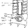
图1-a至1-c为通常的脊椎固定器示意图。1-a to 1-c are schematic diagrams of common spinal fixators.
图2为本发明一较佳具体实施例分解图。Fig. 2 is an exploded view of a preferred embodiment of the present invention.
图3为图2所示较佳具体实施例结合图。Fig. 3 is a combination diagram of the preferred specific embodiment shown in Fig. 2 .
图4-a,4-b,5-a,5-b为图2所示较佳具体实施的角度调整机构示意图。Fig. 4-a, 4-b, 5-a, 5-b are schematic diagrams of the angle adjustment mechanism shown in Fig. 2 in a preferred embodiment.
图6-a,6-b为图2所示较佳具体实施例的高度调整机构示意图。Fig. 6-a, 6-b are schematic diagrams of the height adjustment mechanism of the preferred embodiment shown in Fig. 2 .
图面说明如下:The illustrations are as follows:
110下支撑体 200底座110
111下支撑足 210固定牙111 supporting
112固定凹槽 300顶座112 fixed
120上支撑体 310固定牙120
121上支撑足 410、510凹曲面121
122螺牙 420、520凸曲面122
130调整环 430、440、530、540固定螺丝130 adjusting
131工具孔131 tool hole
450、550固定螺牙 132螺牙450, 550 fixed thread 132 thread
460、560固定孔 133凸肋460, 560 fixing holes 133 convex ribs
具体实施方式 Detailed ways
为进一步说明本发明,现以附图说明已有技术(图1-a至1-c)和本发明较佳具体实施例如下:In order to further illustrate the present invention, the prior art (Fig. 1-a to 1-c) and preferred embodiments of the present invention are as follows with accompanying drawing now:
图1-a至1-c为传统的脊椎固定器,其中10为固定座,11和12分别固定座10的固定牙和固定侧片,20固定座,21和22分别为固定座20的固定牙和固定侧片,31为固定螺丝,32为高度调整机构,40为支撑部件。图1-a为高度调整机构调至较高状态示意图,图1-b显示将固定螺丝31调松,用以将高度调整机构32压入支撑部件40中(参见图1-c)。Figures 1-a to 1-c are traditional spinal fixers, wherein 10 is a fixed seat, 11 and 12 are respectively fixed teeth and fixed side pieces of the fixed seat 10, 20 is a fixed seat, and 21 and 22 are respectively fixed seats 20. Teeth and fixed side pieces, 31 is a set screw, 32 is a height adjustment mechanism, and 40 is a supporting component. Figure 1-a is a schematic diagram of the height adjustment mechanism adjusted to a higher state, and Figure 1-b shows that the fixing screw 31 is loosened to press the height adjustment mechanism 32 into the support member 40 (see Figure 1-c).
图2中,110为支撑部件的下支撑体,111和112为下支撑体的下支撑足和固定凹槽;120为支撑部件的上支撑体,121为上支撑体的上支撑足,122为上支撑足上的螺牙;130为支撑部件的调整环,131、132和133分别为调整环上的工具孔、螺牙和凸肋;200为底座,210为其上的固定牙;300为顶座,310为其上的固定牙;410(510)、420(520)、430(440,530,540)、450(550)、460(560)分别为角度调整机构的凹曲面、凸曲面、固定螺丝、固定螺牙和固定孔。其中凹曲面410、凸曲面420、固定螺丝430,440、固定螺牙450和固定孔460的角度调整机构调整方式参见图4-a,4-b。凹曲面510、凸曲面520、固定螺丝530,540、固定螺牙550和固定孔560的角度调整机构调整方式参见图5-a,5-b。而由上支撑体,下支撑体和调整环所构成的高度调整机构,其调整方式参见图6-a,6-b。Among Fig. 2, 110 is the lower supporting body of support member, and 111 and 112 are the lower supporting foot and fixing groove of lower supporting body; 120 is the upper supporting body of supporting member, and 121 is the upper supporting foot of upper supporting body, and 122 is The screw teeth on the upper support foot; 130 is the adjustment ring of the support component, and 131, 132 and 133 are respectively the tool holes, screw teeth and convex ribs on the adjustment ring; 200 is the base, and 210 is the fixed teeth on it; 300 is the Top seat, 310 is the fixed tooth on it; 410 (510), 420 (520), 430 (440, 530, 540), 450 (550), 460 (560) are the concave surface and convex surface of the angle adjustment mechanism respectively , fixing screws, fixing screws and fixing holes. The angle adjustment mechanism adjustment methods of the
图3为图2的组合图,其中标号111,121,122,130,131,200,210,300,310,430,510,530定义同图2。FIG. 3 is a composite diagram of FIG. 2 , wherein the
图4-a显示底座200和下支撑体110形成正向结合,此时固定螺丝430恰好位于固定孔460中央,其中标号110,111,112,200,210,420,430,460定义同图2。Figure 4-a shows that the
图4-b显示底座200和下支撑体110形成斜向结合,此时固定螺丝430位于固定孔450一侧,其中标号110,111,112,200,210,420,430,460定义同图2。Figure 4-b shows that the
图5-a显示底座200和上支撑体120形成正向结合,此时固定螺丝530恰好位于固定孔560中央,其中标号120,121,122,300,310,530,560定义同图2。FIG. 5-a shows that the
图5-b显示底座200和上支撑体120形成斜向结合,此时固定螺丝530位于固定孔560一侧,其中标号120,121,122,300,310,530,560定义同图2。FIG. 5-b shows that the
图6-a显示上支撑体的每个上支撑足121恰好套在下支撑体的两个下支撑足111间,调整环130环套于下支撑足,并透过调整环内部的凸肋133(参见图2)和下支撑足的固定凹槽112(参见图2)槽合,使下支撑体和调整环结合成一体,而借助调整环130的内部固定凹槽和上支撑体的螺牙122螺合,使上支撑体和调整环结合成一体。其中标号110,121,122,130,131,420,450,520,550定义同图2。Figure 6-a shows that each
图6-b类同,唯有调整环130的内部固定凹槽和上支撑体的固定凹槽122螺合位置不同,因此构成不同长度的支撑部件,其中支撑部件长度(高度)的调整,是以工具顶入工具孔131,并旋动调整环130。Figure 6-b is similar, only the internal fixing groove of the
Claims (5)
Priority Applications (1)
| Application Number | Priority Date | Filing Date | Title |
|---|---|---|---|
| CNB011314044ACN1200650C (en) | 2001-09-06 | 2001-09-06 | Vertebra fixer |
Applications Claiming Priority (1)
| Application Number | Priority Date | Filing Date | Title |
|---|---|---|---|
| CNB011314044ACN1200650C (en) | 2001-09-06 | 2001-09-06 | Vertebra fixer |
Publications (2)
| Publication Number | Publication Date |
|---|---|
| CN1406561A CN1406561A (en) | 2003-04-02 |
| CN1200650Ctrue CN1200650C (en) | 2005-05-11 |
Family
ID=4670558
Family Applications (1)
| Application Number | Title | Priority Date | Filing Date |
|---|---|---|---|
| CNB011314044AExpired - Fee RelatedCN1200650C (en) | 2001-09-06 | 2001-09-06 | Vertebra fixer |
Country Status (1)
| Country | Link |
|---|---|
| CN (1) | CN1200650C (en) |
Families Citing this family (5)
| Publication number | Priority date | Publication date | Assignee | Title |
|---|---|---|---|---|
| CN100539959C (en)* | 2006-08-21 | 2009-09-16 | 叶中权 | Lateral plate spine spinous process opening device |
| DE102007052042A1 (en)* | 2007-10-30 | 2009-05-14 | Kilian Kraus | Height-adjustable spine implant |
| US9700425B1 (en) | 2011-03-20 | 2017-07-11 | Nuvasive, Inc. | Vertebral body replacement and insertion methods |
| CN108451618B (en)* | 2017-02-22 | 2020-10-16 | 医晟有限公司 | spine lamina stabilizer |
| CN107157628A (en)* | 2017-03-29 | 2017-09-15 | 常州华森医疗器械有限公司 | One kind can strut medical titanium cage |
- 2001
- 2001-09-06CNCNB011314044Apatent/CN1200650C/ennot_activeExpired - Fee Related
Also Published As
| Publication number | Publication date |
|---|---|
| CN1406561A (en) | 2003-04-02 |
Similar Documents
| Publication | Publication Date | Title |
|---|---|---|
| US8235994B2 (en) | External fixator | |
| CN1298294C (en) | Spinal osteosynthesis device and preparation method | |
| US20120330364A1 (en) | Modular pedicle screw system | |
| CN1173669C (en) | Bone Fixation device with a rotation joint | |
| US5582612A (en) | Vertebral fixing and retrieving device having centrally two fixation | |
| US6688798B2 (en) | Adjustable locking mount and methods of use | |
| CN1046849C (en) | Spinal fixation system | |
| AU2001285096B2 (en) | A surgical cross-connecting apparatus | |
| US6328739B1 (en) | Enhanced spine fixation apparatus | |
| CN1114099A (en) | Clamps for stabilizing cervical segments | |
| CN1794953A (en) | Connecting device for spinal osteosynthesis | |
| CN1154971C (en) | Adjustable shoulder rest for violins or the like | |
| JPH1043202A (en) | Bone fixing device for fixing to sacrum during backbone jointing operation | |
| US20090204155A1 (en) | Polyaxial bone anchor with headless pedicle screw | |
| CN1352540A (en) | Angle-adjustable bone screw and device for the osteosynthetic bone fixation | |
| JP2014505522A (en) | Spine implant device and method of implanting and using the same | |
| CN1965769A (en) | Bone anchoring device | |
| CN1200650C (en) | Vertebra fixer | |
| JPH05305101A (en) | Vertebral spacer device | |
| CN101039631A (en) | Orthopedic fixation plates having fixation systems for attaching elongated members and method of use | |
| JP2022537024A (en) | Dynamization tabs provide component interconnectivity for external fixation devices | |
| EP0618785A1 (en) | Anterior thoracolumbar plate | |
| US20070173827A1 (en) | Adjustable connector for attachment to a rod in a medical application | |
| CN1406346A (en) | Camera support | |
| CN101053537A (en) | spinous process distraction device |
Legal Events
| Date | Code | Title | Description |
|---|---|---|---|
| C06 | Publication | ||
| PB01 | Publication | ||
| C10 | Entry into substantive examination | ||
| SE01 | Entry into force of request for substantive examination | ||
| C14 | Grant of patent or utility model | ||
| GR01 | Patent grant | ||
| C17 | Cessation of patent right | ||
| CF01 | Termination of patent right due to non-payment of annual fee | Granted publication date:20050511 Termination date:20110906 |