CN1200562A - Drying device and drying method - Google Patents
Drying device and drying methodDownload PDFInfo
- Publication number
- CN1200562A CN1200562ACN97125554ACN97125554ACN1200562ACN 1200562 ACN1200562 ACN 1200562ACN 97125554 ACN97125554 ACN 97125554ACN 97125554 ACN97125554 ACN 97125554ACN 1200562 ACN1200562 ACN 1200562A
- Authority
- CN
- China
- Prior art keywords
- mentioned
- treatment tank
- opening
- drying
- liquid
- Prior art date
- Legal status (The legal status is an assumption and is not a legal conclusion. Google has not performed a legal analysis and makes no representation as to the accuracy of the status listed.)
- Pending
Links
Images


Classifications
- H—ELECTRICITY
- H01—ELECTRIC ELEMENTS
- H01L—SEMICONDUCTOR DEVICES NOT COVERED BY CLASS H10
- H01L21/00—Processes or apparatus adapted for the manufacture or treatment of semiconductor or solid state devices or of parts thereof
- H01L21/02—Manufacture or treatment of semiconductor devices or of parts thereof
- H01L21/04—Manufacture or treatment of semiconductor devices or of parts thereof the devices having potential barriers, e.g. a PN junction, depletion layer or carrier concentration layer
- H01L21/18—Manufacture or treatment of semiconductor devices or of parts thereof the devices having potential barriers, e.g. a PN junction, depletion layer or carrier concentration layer the devices having semiconductor bodies comprising elements of Group IV of the Periodic Table or AIIIBV compounds with or without impurities, e.g. doping materials
- H01L21/30—Treatment of semiconductor bodies using processes or apparatus not provided for in groups H01L21/20 - H01L21/26
- H01L21/302—Treatment of semiconductor bodies using processes or apparatus not provided for in groups H01L21/20 - H01L21/26 to change their surface-physical characteristics or shape, e.g. etching, polishing, cutting
- H01L21/304—Mechanical treatment, e.g. grinding, polishing, cutting
- H—ELECTRICITY
- H01—ELECTRIC ELEMENTS
- H01L—SEMICONDUCTOR DEVICES NOT COVERED BY CLASS H10
- H01L21/00—Processes or apparatus adapted for the manufacture or treatment of semiconductor or solid state devices or of parts thereof
- H01L21/02—Manufacture or treatment of semiconductor devices or of parts thereof
- H01L21/02041—Cleaning
- H01L21/02043—Cleaning before device manufacture, i.e. Begin-Of-Line process
- H01L21/02052—Wet cleaning only
- H—ELECTRICITY
- H01—ELECTRIC ELEMENTS
- H01L—SEMICONDUCTOR DEVICES NOT COVERED BY CLASS H10
- H01L21/00—Processes or apparatus adapted for the manufacture or treatment of semiconductor or solid state devices or of parts thereof
- H01L21/67—Apparatus specially adapted for handling semiconductor or electric solid state devices during manufacture or treatment thereof; Apparatus specially adapted for handling wafers during manufacture or treatment of semiconductor or electric solid state devices or components ; Apparatus not specifically provided for elsewhere
- H01L21/67005—Apparatus not specifically provided for elsewhere
- H01L21/67011—Apparatus for manufacture or treatment
- H01L21/67017—Apparatus for fluid treatment
- H01L21/67028—Apparatus for fluid treatment for cleaning followed by drying, rinsing, stripping, blasting or the like
- H01L21/67034—Apparatus for fluid treatment for cleaning followed by drying, rinsing, stripping, blasting or the like for drying
Landscapes
- Engineering & Computer Science (AREA)
- Physics & Mathematics (AREA)
- Condensed Matter Physics & Semiconductors (AREA)
- General Physics & Mathematics (AREA)
- Manufacturing & Machinery (AREA)
- Computer Hardware Design (AREA)
- Microelectronics & Electronic Packaging (AREA)
- Power Engineering (AREA)
- Cleaning Or Drying Semiconductors (AREA)
- Drying Of Solid Materials (AREA)
Abstract
Translated fromChinese
Description
Translated fromChinese本发明涉及适合干燥半导体晶片的干燥技术,特别是涉及为了控制干燥不良而进行的改进。The present invention relates to a drying technique suitable for drying semiconductor wafers, and in particular to an improvement for controlling drying failure.
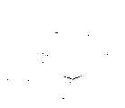
图27是作为本发明背景的传统干燥装置结构的正剖面图。该干燥装置151是以半导体晶片的干燥为目的而构成的装置。在装置151上设有上方开口的处理槽171。在处理槽171侧壁上方部分的内侧,沿处理槽171的侧壁安装冷却盘旋管162。冷却盘旋管162采用石英管,冷却水在其内部流动。Fig. 27 is a front sectional view showing the structure of a conventional drying apparatus as the background of the present invention. The drying device 151 is configured for the purpose of drying the semiconductor wafer. The device 151 is provided with a treatment tank 171 with an upper opening. On the inner side of the upper portion of the side wall of the processing tank 171 , a cooling coil pipe 162 is installed along the side wall of the processing tank 171 . The cooling coil 162 is a quartz tube, and cooling water flows inside it.
在处理槽171底部的正下方设置加热器170。并且,在处理槽171的内部,在底部与上方开口端之间的位置固定接受器皿166。在该接受器皿166的底部连接排水用的配管180。A heater 170 is provided directly below the bottom of the processing tank 171 . Furthermore, in the processing tank 171, the receiving vessel 166 is fixed at a position between the bottom and the upper opening end. A pipe 180 for drainage is connected to the bottom of the receiving container 166 .
在使用装置151的时候,首先在处理槽171的内部注入IPA液167(异丙醇)。调整处理槽171的深度使液面达不到接受器皿166的底部。而且,使冷却水在冷却盘旋管162的内部流动。When the device 151 is used, first, the IPA solution 167 (isopropyl alcohol) is injected into the treatment tank 171 . The depth of the processing tank 171 is adjusted so that the liquid level does not reach the bottom of the receiving vessel 166 . Furthermore, cooling water is made to flow inside the cooling coil 162 .
打开加热器170,加热IPA液167。结果,IPA液167被气化,产生IPA蒸汽165。该IPA蒸汽165充满处理槽171的内部。IPA蒸汽165在冷却盘旋管162附近由于被冷却而凝结。即,冷却盘旋管162起到防止IPA蒸汽165漏到处理槽171外面的作用。The heater 170 is turned on to heat the IPA liquid 167 . As a result, the IPA liquid 167 is vaporized, and the IPA vapor 165 is generated. This IPA steam 165 fills the inside of the processing tank 171 . The IPA vapor 165 condenses near the cooling coil 162 as it is cooled. That is, the cooling coil pipe 162 functions to prevent the IPA steam 165 from leaking out of the treatment tank 171 .
因此,在处理槽171的内部,在底部附近的液体储存部169内储存IPA液167;而在蒸汽填充部168内充满IPA蒸汽165。蒸汽填充部168是从液体储存部169的上方直到设置冷却盘旋管162附近的空间。在蒸汽填充部168内充满IPA蒸汽165之后,开始对作为处理对象的半导体晶片163进行处理。即,将多块半导体晶片163和装载它们的容器164在水洗处理完后用保持吊臂161吊下,并从处理槽171的上方插入蒸汽填充部168内。如图27所示,装有半导体晶片163的容器164由保持吊臂161保持在接受器皿166正上方的位置。Therefore, in the treatment tank 171 , the IPA liquid 167 is stored in the liquid storage part 169 near the bottom; and the IPA vapor 165 is filled in the vapor filling part 168 . The steam filling part 168 is a space from above the liquid storage part 169 to the vicinity where the cooling coil 162 is provided. After the steam filling part 168 is filled with the IPA steam 165, the semiconductor wafer 163 to be processed is started to be processed. That is, the plurality of semiconductor wafers 163 and the container 164 containing them are suspended by the holding boom 161 after the water washing process, and inserted into the steam filling part 168 from above the processing tank 171 . As shown in FIG. 27 , a container 164 containing a semiconductor wafer 163 is held by a holding arm 161 at a position directly above a receiving vessel 166 .
这样,充满蒸汽填充部168的IPA蒸汽165凝结溶入到附着在半导体晶片163及容器164表面的水滴中。其结果是水滴实质上变成了IPA的液滴,并从半导体晶片163和容器164的表面滑落下来。由此而实现了被水滴润湿的半导体晶片163和容器164的干燥。滑落下来的IPA液滴由接受器皿166回收并通过配管180排到外部。In this way, the IPA vapor 165 filling the vapor filling portion 168 condenses and dissolves into the water droplets adhering to the surfaces of the semiconductor wafer 163 and the container 164 . As a result, the water droplets become substantially IPA droplets and slide off the surfaces of the semiconductor wafer 163 and the container 164 . This achieves drying of the semiconductor wafer 163 and the container 164 wetted by the water droplets. The dropped IPA droplets are collected by the receiving container 166 and discharged to the outside through the pipe 180 .
当干燥处理结束后,容器164被保持吊臂161拉上,从处理槽171中取出。之后,将取出的容器164送到下一个处理工序。而在处理槽171内放入新的半导体晶片163和容器164。这样,可反复进行半导体晶片163和容器164的干燥处理。After the drying process is finished, the container 164 is pulled up by the holding arm 161 and taken out from the processing tank 171 . Thereafter, the container 164 taken out is sent to the next processing step. On the other hand, a new semiconductor wafer 163 and container 164 are placed in the processing tank 171 . In this way, the drying process of the semiconductor wafer 163 and the container 164 can be repeated.
然而,由于传统装置151是将作为处理对象的半导体晶片163沐浴在IPA蒸汽165中,并通过使IPA蒸汽165在其表面凝结来实现对表面的干燥,所以,存在这样的问题:在不能充分得到IPA蒸汽165凝结量的条件下,就不能进行充分的干燥,从而产生干燥不良的现象。However, since the conventional device 151 is to bathe the semiconductor wafer 163 as the processing object in the IPA steam 165, and to realize the drying of the surface by making the IPA steam 165 condense on its surface, there is a problem that the wafer 163 cannot be sufficiently obtained. Under the condition of the condensation amount of IPA steam 165, sufficient drying cannot be performed, resulting in poor drying.
特别是IPA蒸汽165不仅在投入的作为处理对象的半导体晶片163上凝结,也在处理槽171的内壁表面等不必要的部位凝结,因此,有时会使IPA蒸汽165的凝结量不充分。而半导体晶片163上的干燥不良是导致装有半导体晶片163的半导体装置合格率低下的主要原因之一。In particular, the IPA steam 165 condenses not only on the semiconductor wafer 163 to be processed, but also on unnecessary parts such as the inner wall surface of the processing tank 171. Therefore, the amount of condensation of the IPA steam 165 may be insufficient. The poor drying on the semiconductor wafer 163 is one of the main reasons for the low yield of semiconductor devices equipped with the semiconductor wafer 163 .
本发明的目的是为解决传统技术中的上述问题而提出的一种可抑制干燥不良的干燥技术。The object of the present invention is to propose a drying technique capable of suppressing poor drying in order to solve the above-mentioned problems in the conventional technique.
第1发明装置是用水溶性的溶媒液对处理对象表面进行干燥的干燥装置。在该干燥装置上设有处理槽。该处理槽在上部具有向上开口并可取出放入上述处理对象的开口部,并可在底部储存前述溶媒液,而且在该储存的溶媒液上方可放入上述处理对象。The apparatus of the first invention is a drying apparatus for drying a surface to be treated with a water-soluble solvent. A treatment tank is provided on the drying device. The treatment tank has an opening upwardly opened at the upper part and can be taken out and put in the above-mentioned treatment object, and the above-mentioned solvent solution can be stored at the bottom, and the above-mentioned treatment object can be placed above the stored solvent solution.
而且,上述装置还设有加热装置、扩散防止装置、喷嘴、液体回收装置。其中,加热装置可以加热储存在上述处理槽底部的上述溶媒液;扩散防止装置用于防止上述溶媒液加热后产生的蒸汽通过上述开口部而从上述处理槽内部扩散到外部;喷嘴通过向其提供上述溶媒液,可沿上述处理槽的侧壁的内侧表面形成流动的上述溶媒液的流体以覆盖该内侧表面;液体回收装置回收流过上述内侧表面的上述溶媒液,并导向上述处理槽的外部。Moreover, the above-mentioned device is further provided with a heating device, a diffusion prevention device, a nozzle, and a liquid recovery device. Wherein, the heating device can heat the above-mentioned solvent liquid stored at the bottom of the above-mentioned treatment tank; the diffusion prevention device is used to prevent the steam generated after the above-mentioned solvent liquid is heated from diffusing from the inside of the above-mentioned treatment tank to the outside through the above-mentioned opening; The above-mentioned solvent solution can form a flow of the above-mentioned solvent solution flowing along the inner surface of the side wall of the above-mentioned treatment tank to cover the inner surface; the liquid recovery device recovers the above-mentioned solvent solution flowing through the above-mentioned inner surface, and guides it to the outside of the above-mentioned treatment tank .
第2发明装置是在第1发明的干燥装置上还设有循环装置。该循环装置将上述液体回收装置回收的上述溶媒液再导向前述喷嘴,由此而向该喷嘴循环提供上述溶媒液。In the apparatus of the second invention, the drying apparatus of the first invention is further provided with a circulation device. The circulation device guides the solvent liquid recovered by the liquid recovery device to the nozzle, thereby circulating the solvent liquid to the nozzle.
第3发明装置是用水溶性的溶媒液对处理对象表面进行干燥的干燥装置。在该干燥装置上设有处理槽。该处理槽在上部具有向上开口并可放入取出上述处理对象的开口部,并可在底部储存溶媒液;而且在储存的溶媒液中可浸泡上述处理对象,并且,在该储存的溶媒液上方可放入上述处理对象。The apparatus of the third invention is a drying apparatus for drying the surface to be treated with a water-soluble solvent. A treatment tank is provided on the drying device. The treatment tank has an upward opening at the top and can put in and take out the opening of the above-mentioned treatment object, and can store a solvent solution at the bottom; Can be placed in the above processing object.
上述干燥装置还设有加热装置和扩散防止装置。其中,加热装置可以加热储存在上述处理槽底部的上述溶媒液;扩散防止装置用于防止上述溶媒液加热后产生的蒸汽通过上述开口部而从上述处理槽内部扩散到外部。The above-mentioned drying device is also provided with a heating device and a diffusion prevention device. Wherein, the heating device can heat the above-mentioned solvent liquid stored at the bottom of the above-mentioned treatment tank; the diffusion prevention device is used to prevent the steam generated after the above-mentioned solvent liquid is heated from diffusing from the inside of the above-mentioned treatment tank to the outside through the above-mentioned opening.
第4发明装置是在第3发明的干燥装置上还设有再处理装置。该再处理装置回收储存在上述处理槽底部的上述溶媒液,并从回收的上述溶媒液中除去水分,之后再返回上述处理槽,从而将储存的上述溶媒液进行循环再处理。In the apparatus of the fourth invention, the drying apparatus of the third invention is further provided with a reprocessing apparatus. The reprocessing device recovers the solvent solution stored at the bottom of the treatment tank, removes moisture from the recovered solvent solution, and then returns it to the treatment tank, thereby recycling the stored solvent solution for reprocessing.
第5发明装置是在第3发明或第4发明的干燥装置上,上述扩散防止装置设有在上述开口部两侧相向设置的喷出装置和排气装置。而且,上述排气装置的排气口的开口朝向上述喷出装置;在有气体供给时,上述喷出装置可形成朝向上述排气口、并覆盖上述开口部的上述气体的喷流;上述排气装置可将通过上述排气口吸入的上述气体排向外部;上述处理槽的侧壁设有随着从下方接近上述开口部而向内侧圆滑弯曲的弯曲部。The device of the fifth invention is the drying device according to the third invention or the fourth invention, wherein the diffusion preventing means is provided with a spraying means and an exhaust means provided opposite to each other on both sides of the opening. Moreover, the opening of the exhaust port of the above-mentioned exhaust device faces the above-mentioned ejection device; when there is gas supply, the above-mentioned ejection device can form a jet flow of the above-mentioned gas that faces the above-mentioned exhaust port and covers the above-mentioned opening; The gas device can discharge the above-mentioned gas sucked through the above-mentioned exhaust port to the outside; the side wall of the above-mentioned treatment tank is provided with a curved portion that is smoothly curved inward as it approaches the above-mentioned opening from below.
上述干燥装置还设有配管、惰性气体供给装置和冷却装置。其中,配管与上述喷出装置连接;惰性气体供给装置通过该配管连接到上述喷出装置上并向该喷出装置提供惰性气体;冷却装置设在上述配管的至少一部分上,用于冷却流过该配管的上述惰性气体。The above-mentioned drying device is further provided with piping, an inert gas supply device, and a cooling device. Wherein, the pipe is connected to the above-mentioned spraying device; the inert gas supply device is connected to the above-mentioned spraying device through the pipe and supplies the inert gas to the spraying device; the cooling device is arranged on at least a part of the above-mentioned pipe for cooling the The above-mentioned inert gas for the piping.
第6发明装置是在第3发明或第4发明的干燥装置上,上述扩散防止装置设有在上述开口部两侧相向设置的喷出装置和排气装置。而且,上述排气装置的排气口的开口朝向上述喷出装置;在有气体供给时,上述喷出装置可形成朝向上述排气口、并覆盖上述开口部的上述气体的喷流;上述排气装置可将通过上述排气口吸入的上述气体排向外部;上述处理槽的侧壁设有随着从下方接近上述开口部而向内侧圆滑弯曲的弯曲部。The apparatus of the sixth invention is the drying apparatus of the third invention or the fourth invention, wherein the diffusion preventing means is provided with a spraying means and an exhaust means provided opposite to each other on both sides of the opening. Moreover, the opening of the exhaust port of the above-mentioned exhaust device faces the above-mentioned ejection device; when there is gas supply, the above-mentioned ejection device can form a jet flow of the above-mentioned gas that faces the above-mentioned exhaust port and covers the above-mentioned opening; The gas device can discharge the above-mentioned gas sucked through the above-mentioned exhaust port to the outside; the side wall of the above-mentioned treatment tank is provided with a curved portion that is smoothly curved inward as it approaches the above-mentioned opening from below.
上述干燥装置还设有切换阀、供给常温惰性气体的常温气体供给装置、供给冷却惰性气体的冷却气体供给装置、以及控制该切换阀切换动作的控制器。该切换阀其输出方连接上述喷出装置,并可自由切换地选择多个输入方中的一方并连通输出方。The drying device is further provided with a switching valve, a normal temperature gas supply device for supplying a normal temperature inert gas, a cooling gas supply device for supplying a cooling inert gas, and a controller for controlling the switching operation of the switching valve. The output side of the switching valve is connected to the above-mentioned discharge device, and one of the plurality of input sides can be freely switched and connected to the output side.
而且,上述多个输入方中的一方连接上述常温惰性气体供给装置、上述多个输入方中的另一方连接上述冷却惰性气体供给装置;上述控制器是只在上述处理对象横切上述喷出装置形成的上述喷流而放入上述处理槽内部时,控制上述切换阀以使上述喷流变成冷却的上述惰性气体的喷流。Moreover, one of the above-mentioned multiple input sides is connected to the above-mentioned normal temperature inert gas supply device, and the other of the above-mentioned multiple input sides is connected to the above-mentioned cooling inert gas supply device; When the formed jet flow is introduced into the treatment tank, the switching valve is controlled so that the jet flow becomes a jet flow of the cooled inert gas.
第7发明装置是在第3发明或第4发明的干燥装置上,上述扩散防止装置设有冷却装置。该冷却装置设在上述处理槽接近上述开口部的部分,以冷却上述处理槽开口部附近的内侧,使其可以冷却通过上述开口部而放入上述处理槽中的上述处理对象。A seventh invention is the drying device according to the third invention or the fourth invention, wherein the diffusion preventing means is provided with a cooling means. The cooling device is provided at a portion of the treatment tank close to the opening to cool the inside near the opening of the treatment tank so that the treatment object put into the treatment tank through the opening can be cooled.
第8发明装置是在第3发明或第4发明的干燥装置上,还设有与上述处理槽相邻连接的冷却水洗装置。该冷却水洗装置在上部具有向上开口并可放入取出上述处理对象的开口部,可储存清洗用水;并且,该冷却水洗装置设有水洗槽和冷却装置,该水洗槽可将上述处理对象浸泡在该储存的清洗用水中,而冷却装置安装在上述水洗槽中,用于冷却上述清洗用水。The apparatus of the 8th invention is the drying apparatus of the 3rd invention or the 4th invention, and the cooling water washing apparatus connected adjacently to the said processing tank is further provided. The cooling water washing device has an upward opening on the top and can put in and take out the opening of the above-mentioned processing object, and can store cleaning water; and, the cooling water washing device is provided with a water washing tank and a cooling device, and the water washing tank can soak the above-mentioned processing object in The stored cleaning water is placed in the washing tank, and the cooling device is installed in the washing tank for cooling the cleaning water.
第9发明装置,是用水溶性的溶媒液对处理对象表面进行干燥的干燥装置。在该干燥装置上设有处理槽。该处理槽在上部具有向上开口并可放入取出上述处理对象的开口部,并可在底部储存溶媒液;并且在该储存的溶媒液上方可放入上述处理对象。The apparatus of the ninth invention is a drying apparatus for drying a surface to be treated with a water-soluble solvent. A treatment tank is provided on the drying device. The treatment tank has an upward opening on the upper part and an opening for taking out the above-mentioned treatment object, and can store a solvent solution at the bottom; and the above-mentioned treatment object can be placed above the stored solvent solution.
上述干燥装置还设有加热装置、扩散防止装置和喷嘴。其中,加热装置可以加热储存在上述处理槽底部的上述溶媒液;该扩散防止装置用于防止上述溶媒液加热后产生的蒸汽通过上述开口部而从上述处理槽内部扩散到外部;该喷嘴通过向其提供上述溶媒液,向上述处理槽的内部喷射雾状的上述溶媒液。The above-mentioned drying device is further provided with a heating device, a diffusion preventing device and a nozzle. Wherein, the heating device can heat the above-mentioned solvent liquid stored at the bottom of the above-mentioned treatment tank; the diffusion prevention device is used to prevent the steam generated after the above-mentioned solvent liquid is heated from passing through the above-mentioned opening to diffuse from the inside of the above-mentioned treatment tank to the outside; It supplies the above-mentioned solvent solution, and sprays the above-mentioned solvent solution in a mist form into the inside of the above-mentioned treatment tank.
第10发明装置是用水溶性的溶媒液对处理对象表面进行干燥的干燥装置。在该干燥装置上设有处理槽。该处理槽在上部具有向上开口并可取出放入上述处理对象的开口部,并可在底部储存溶媒液,而且在该储存的溶媒液上方可放入上述处理对象。The apparatus of the tenth invention is a drying apparatus for drying a surface to be treated with a water-soluble solvent. A treatment tank is provided on the drying device. The processing tank has an opening upwardly opened at the upper part and can be taken out and put in the above-mentioned processing object, and a solvent liquid can be stored at the bottom, and the above-mentioned processing object can be put in above the stored solvent liquid.
上述干燥装置还设有加热装置、扩散防止装置、冷却水洗装置和控制装置。其中,加热装置可以加热储存在上述处理槽底部的上述溶媒液;扩散防止装置用于防止上述溶媒液加热后产生的蒸汽通过上述开口部而从上述处理槽内部扩散到外部;冷却水洗装置与上述处理槽相邻设置;该控制装置控制上述加热装置。The above-mentioned drying device is also provided with a heating device, a diffusion prevention device, a cooling water washing device and a control device. Wherein, the heating device can heat the above-mentioned solvent liquid stored at the bottom of the above-mentioned treatment tank; the diffusion prevention device is used to prevent the steam generated after the above-mentioned solvent liquid is heated from diffusing from the inside of the above-mentioned treatment tank to the outside through the above-mentioned opening; the cooling water washing device and the above-mentioned The treatment tanks are arranged adjacently; the control device controls the above-mentioned heating device.
而且,该冷却水洗装置设有水洗槽和传感器;该水洗槽在上部具有向上开口、并可取出放入上述处理对象的开口部,并可储存清洗用水,而且可将上述处理对象浸泡在该储存的清洗用水中;而传感器安装在上述水洗槽上,可检测在该水洗槽中是否有上述处理对象,并且向上述控制装置发送检测信号。Moreover, this cooling water washing device is provided with a water washing tank and a sensor; the water washing tank has an upward opening at the top, and an opening that can be taken out and put into the above-mentioned processing object, and can store cleaning water, and the above-mentioned processing object can be soaked in the storage. In the cleaning water; and the sensor is installed on the above-mentioned water-washing tank, which can detect whether there is the above-mentioned processing object in the water-washing tank, and send a detection signal to the above-mentioned control device.
并且,上述控制装置根据上述检测信号来控制上述加热器的输出,以补偿充满上述处理槽的蒸汽的热量损失,这部分热量是上述处理对象从上述水洗槽移放到上述处理槽中的时候吸去的。And, the above-mentioned control device controls the output of the above-mentioned heater according to the above-mentioned detection signal, so as to compensate for the heat loss of the steam filled with the above-mentioned treatment tank. to go.
第11发明装置是在第1发明至第4发明、或第9发明及第10发明的任何一种干燥装置上,上述扩散防止装置设有在上述开口部两侧相向设置的喷出装置和排气装置。The device of the eleventh invention is any one of the drying devices of the first to fourth inventions, or the ninth invention and the tenth invention, wherein the above-mentioned diffusion prevention device is provided with a spray device and a discharge device arranged oppositely on both sides of the above-mentioned opening. gas device.
而且,上述排气装置的排气口的开口朝向上述喷出装置;在有气体供给时,上述喷出装置可形成朝向上述排气口并覆盖上述开口部的上述气体的喷流;上述排气装置可将通过上述排气口吸入的上述气体排向外部;上述处理槽的侧壁设有随着从下方接近上述开口部而向内侧圆滑弯曲的弯曲部。Moreover, the opening of the exhaust port of the above-mentioned exhaust device faces the above-mentioned ejection device; when there is gas supply, the above-mentioned ejection device can form a jet flow of the above-mentioned gas directed towards the above-mentioned exhaust port and covering the above-mentioned opening; The device can discharge the gas sucked through the exhaust port to the outside; the side wall of the treatment tank is provided with a curved portion that is smoothly curved inward as it approaches the opening from below.
第12发明的方法是在用水溶性的溶媒液对处理对象表面进行干燥的干燥方法中,设有在该干燥装置上准备处理槽的工序。该处理槽在上部具有向上开口并可取出放入上述处理对象的开口部,并可在底部储存溶媒液;而且,在储存的溶媒液中可浸泡上述处理对象,并且,在该储存的溶媒液上方可放入上述处理对象。In the method of the twelfth invention, in the drying method of drying the surface of the treatment object with a water-soluble solvent, a step of preparing a treatment tank on the drying device is provided. The treatment tank has an upward opening at the top and can be taken out to put into the opening of the above-mentioned treatment object, and can store a solvent solution at the bottom; and, the above-mentioned treatment object can be soaked in the stored solvent solution, and The above processing objects can be placed above.
上述干燥方法还设有以下工序:在上述处理槽的底部储存足可浸泡上述处理对象的上述溶媒液的工序;加热储存的上述溶媒液,使该溶媒液的蒸汽充满上述处理槽的工序;通过上述开口部将上述处理对象从外部放入上述处理槽内的工序;将放入的上述处理对象在充满的上述蒸汽中向上述处理溶媒液下降的下降工序。The above-mentioned drying method is also provided with the following steps: storing the above-mentioned solvent solution enough to soak the above-mentioned treatment object at the bottom of the above-mentioned treatment tank; A step of putting the object to be processed into the processing tank from the outside in the opening; a descending step of lowering the object to be processed into the processing medium in the filled steam.
并且,上述干燥方法还设有以下工序:通过将上述处理对象浸泡到储存的上述溶媒液中,而将附着在上述处理对象表面的水分除去的工序;通过将上述处理对象从上述溶媒液中取出并沐浴在充满的上述蒸汽中而将残留在上述处理对象表面的上述溶媒液去除的工序;通过上述开口部从上述处理槽中取出上述处理对象的工序。Moreover, the above-mentioned drying method is further provided with the following steps: by soaking the above-mentioned processing object in the stored above-mentioned solvent solution, and removing the moisture attached to the surface of the above-mentioned processing object; by taking the above-mentioned processing object out of the above-mentioned solvent liquid and bathing in the filled steam to remove the above-mentioned solvent liquid remaining on the surface of the above-mentioned processing object; and the process of taking out the above-mentioned processing object from the above-mentioned processing tank through the above-mentioned opening.
第13发明的干燥方法是在第17发明的干燥方法中还设有在上述下降工序之前对上述处理对象进行冷却的工序。In the drying method of the 13th invention, in the drying method of the 17th invention, a step of cooling the object to be treated is further provided before the lowering step.
第14发明的干燥方法是在第17发明的干燥方法中还设有在上述下降工序之前将上述处理对象浸泡在冷却的清洗用水中进行水洗的工序。The drying method of the 14th invention is the drying method of the 17th invention further comprising a step of washing the object to be treated by immersing it in cooled washing water before the lowering step.
第15发明的干燥方法是在利用第1发明至第4发明、或第9发明及第10发明的任何一种干燥装置对处理对象表面进行干燥的干燥方法中设有以下工序:准备上述干燥装置的工序;通过向上述处理槽中提供上述溶媒液而在上述处理槽的一部分储存上述溶媒液的工序;起动上述加热装置加热上述溶媒液的工序;穿过上述开口部将上述处理对象放入上述处理槽中的工序。The drying method of the fifteenth invention is to use any one of the drying devices of the first invention to the fourth invention, or the ninth invention and the tenth invention to dry the surface of the treatment object, and the following steps are provided: the above-mentioned drying device is prepared. the process of storing the above-mentioned solvent liquid in a part of the above-mentioned processing tank by supplying the above-mentioned solvent liquid into the above-mentioned processing tank; the process of activating the above-mentioned heating device to heat the above-mentioned solvent liquid; Process in the processing tank.
上述干燥方法还设有以下工序:将放入的上述处理对象保持在上述溶媒液的液面上方并利用加热后的上述溶媒液所产生的蒸汽对上述处理对象表面进行干燥的干燥处理工序;在该干燥处理工序后,穿过上述开口部将上述处理对象从上述处理槽内取出的工序。The above-mentioned drying method is also provided with the following steps: the above-mentioned processing object that is put in is kept above the liquid surface of the above-mentioned solvent liquid, and the steam generated by the heated above-mentioned solvent liquid is used to dry the surface of the above-mentioned processing object; After the drying treatment step, a step of taking out the treatment object from the treatment tank through the opening.
图1实施形式1的装置的斜视剖面图。Fig. 1 is an oblique sectional view of the device of
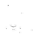
图2作为各实施形式基础装置的正剖面图。Fig. 2 is a front sectional view of the foundation device of each embodiment.
图3实施形式1的装置的正剖面图。Fig. 3 is a front sectional view of the device of
图4实施形式1的另一装置例的正剖面图。Fig. 4 is a front sectional view of another device example of
图5实施形式2的装置的正剖面图。Fig. 5 is a front sectional view of the device of
图6实施形式3的装置的正剖面图。Fig. 6 is a front sectional view of the device of
图7实施形式3的另一装置例的正剖面图。Fig. 7 is a front sectional view of another device example of
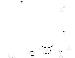
图8实施形式4的装置的正剖面图。Fig. 8 is a front sectional view of the device of
图9采用实施形式4的装置的处理流程图。FIG. 9 is a flow chart of the processing of the device in
图10采用实施形式4的装置的处理流程图。Fig. 10 is a flow chart of the processing of the device in
图11实施形式5的装置的正剖面图。Fig. 11 is a front sectional view of the device of
图12实施形式6的装置的正剖面图。Fig. 12 is a front sectional view of the device of
图13实施形式7的装置的正剖面图。Fig. 13 is a front sectional view of the device of
图14实施形式8的装置的正剖面图。Fig. 14 is a front sectional view of the device of
图15采用实施形式8的装置的处理流程图。Fig. 15 is a flow chart of the processing of the device in the eighth embodiment.
图16采用实施形式8的装置的处理流程图。Fig. 16 is a flow chart of the processing of the device in the eighth embodiment.
图17实施形式8的另一装置例的正剖面图。Fig. 17 is a front sectional view of another device example of the eighth embodiment.
图18实施形式8的又一装置例的结构示意图。Fig. 18 is a schematic structural diagram of yet another device example of
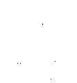
图19实施形式9的装置的正剖面图。Fig. 19 is a front sectional view of the device of
图20采用实施形式9的装置的处理流程图。Fig. 20 is a flow chart of the processing of the device of the ninth embodiment.
图21实施形式10的装置的正剖面图。Fig. 21 is a front sectional view of the device of
图22实施形式11的装置的正剖面图。Fig. 22 is a front sectional view of the device of
图23采用实施形式11的装置的处理流程图。Fig. 23 is a flow chart of the processing of the device of the eleventh embodiment.
图24实施形式11的另一装置例的正剖面图。Fig. 24 is a front sectional view of another device example of
图25实施形式12的装置的结构示意图。Fig. 25 is a schematic structural diagram of the device in Embodiment 12.
图26变形例的装置的正剖面图。Fig. 26 is a front sectional view of a device of a modified example.
图27传统装置的正剖面图。Figure 27 is a front sectional view of a conventional device.
首先,对作为以下各实施形式基础技术之一的干燥装置100与传统装置151一起进行说明。另外,在以下的各实施形式中,主要是以干燥装置100为基础例示,但同样也可以传统装置151为基础进行实施。First, the drying device 100, which is one of the basic technologies of the following embodiments, will be described together with the conventional device 151. In addition, in each of the following embodiments, the drying device 100 is mainly used as an example, but the conventional device 151 can also be implemented similarly.
图2是干燥装置100的结构的正剖面图。干燥装置100与传统装置151一样是以半导体晶片3的干燥为目的而构成的装置。如图2所示,在干燥装置100上设有处理槽11。处理槽11是只在上部开口的容器。即,在处理槽11的上部具有向上方开口的开口部22。而且,处理槽11的侧壁在其上端附近随着从下方逐渐接近开口部22而向内侧圆滑弯曲。FIG. 2 is a front sectional view of the structure of the drying device 100 . The drying apparatus 100 is configured for the purpose of drying the
在处理槽11的上部,在上述开口部22两侧相对设置一列喷嘴13(喷出装置)以及槽状的排气构件14(排气装置)。这些喷嘴13分别与配管19的一端连接。而该配管19的另一端与氮气供给装置18连接。氮气供给装置18例如是可作为工厂设施之一的装置。设在排气装置14上的排气口开口向着喷嘴13。On the upper part of the
在处理槽11的上部还设有可自由开闭开口部22的盖15。为了使盖15开闭自由,例如图2所示,设计与盖15连接的操纵器24。操纵器24根据图中未示出的控制器发出的信号,通过使盖15向水平方向移动来开闭盖15。A
另外,在处理槽11底部的正下方设置加热器10(第1加热器)。并且在处理槽11的内部,在底部与上方开口部22之间的位置固定接受器皿6。在该接受器皿6的底部连接排水用配管20的一端,该配管20贯通处理槽11的侧壁并引向外部。In addition, a heater 10 (first heater) is provided directly below the bottom of the
该装置100按以下的顺序使用。首先,在处理槽11的内部供给适合干燥水洗后半导体晶片3的溶剂,例如IPA液7(溶媒液)。调节所供给的IPA液7的量以使液面低于接受器皿6底部的位置。并且,在盖15关闭的状态下给加热器10通电。This device 100 is used in the following order. First, a solvent suitable for drying the
这样,加热器10产生的热通过处理槽11的底部传递给IPA液7。加热IPA液7的目的是使IPA液7气化,由此产生IPA蒸汽5。该IPA蒸汽5充满处理槽11的内部。即,处理槽11的内部被分为储存IPA液7的液体储存部9和位于上部的充满IPA蒸汽5的蒸汽填充部8。In this way, the heat generated by the
在把水洗处理后的半导体晶片3放入处理槽11之前,来自氮气供给装置18的氮气通过配管19提供给喷嘴13。这样,氮气从喷嘴13喷出。由于喷嘴13是列状设置的,所以,喷出的氮气——即氮气的喷流21形成膜状并将开口部22完全覆盖。而喷流21回收到面向喷嘴13开口的排气装置14的排气口。排气装置14可将通过排气口吸入的喷流21排向外部。Nitrogen gas from a nitrogen
喷流21喷射期间,盖15打开,将作为处理对象的半导体晶片3放入处理槽11。即,将多块半导体晶片3和装载它们的容器4,在水洗处理完后用与保持吊臂161(参见图27)相同的保持吊臂吊下,从开口部22的上方横切喷流21,通过开口部22而插入蒸汽填充部8内。如图2所示,把装有半导体晶片3的容器4放在接受器皿6上。然后,将保持吊臂提升到外部。在保持吊臂移到外部后,关闭盖15,可以停止喷射喷流21。While the
由于半导体晶片3及容器4放在蒸汽填充部8内,所以,充满蒸汽填充部8的IPA蒸汽5凝结溶入附着在半导体晶片3及容器4表面的水滴中。因为1PA在水中的溶解度高,所以大量溶入水滴中。其结果是将水滴实质上变成了IPA的液滴,重量增加。然后由于其重量的作用,IPA的液滴从半导体晶片3和容器4的表面滑落下来。Since the
这样,就实现了被水滴润温的半导体晶片3和容器4的干燥。滑落下来的IPA的液滴由接受器皿6回收,并通过配管20排到外部。即,混有水滴和微量杂质的IPA液体不会混入IPA液7中,而是排到处理槽11的外面。从而保持了储存在液体储存部9的IPA液7的高纯度。In this way, the drying of the
当半导体晶片3和容器4干燥处理完后,再次形成喷流21,打开盖15。然后,再次将保持吊臂插入处理槽11中,由保持吊臂将装载半导体晶片3的容器4向上提起,横切喷流21并通过开口部22从处理槽11中取出。之后,将取出的半导体晶片3以及容器4送到下一个处理工序。而后在处理槽11的蒸汽填充部8内放入新的半导体晶片3和容器4。这样,可反复进行半导体晶片3和容器4的干燥处理。After the
在对半导体晶片3和容器4进行干燥处理时,也可用保持吊臂将半导体晶片3和容器4置于蒸气填充部8中的接受器皿6的上方,以取代将它们放置在接受器皿6上。这时,既使在进行干燥处理期间,也可以打开盖15,且不停止喷射喷流21。The
当作为处理对象的半导体晶片3和容器4放入处理槽11以及从处理槽11中取出时、还可以根据情况在进行干燥处理的时候,将盖15打开,并形成喷流21。尽管盖15是打开的,但IPA蒸汽5由于受到覆盖开口部22的喷流21的阻挡,难以通过开口部22从处理槽11中扩散出来。即,IPA蒸汽5基本都滞留在蒸汽填充部8内。即,喷流21起到阻止气体通过的一种屏障作用。When the
在装置100上,不但喷流21有效地发挥了屏障的功能,而且处理槽11的形状也起到很大的作用。如图2所示,由IPA液7产生的IPA蒸汽5沿处理槽11的侧壁面上升。而如前所述,处理槽11的侧壁是在开口部22附近随着接近开口部22而向内侧圆滑弯曲的。In the apparatus 100, not only the
所以,IPA蒸汽5的气流在处理槽11的上部附近沿侧壁的弯曲部向内侧圆滑弯曲。IPA蒸汽5在蒸汽填充部8的上部冷却的结果,是IPA蒸汽5的气流逐渐向下流动。即,如图2所示,在蒸汽填充部8中,沿流线23产生了IPA蒸汽5的对流。结果,由喷流21有效地阻止了充满蒸汽填充部8的IPA蒸汽5通过开口部22向外面流出。Therefore, the air flow of the
由于在装置100上形成了喷流21,所以,不必设置传统装置151上必需的冷却盘旋管162。因此,消除了由于提供给冷却盘旋管162的制冷剂状态的变化而引起的IPA蒸汽165状态的不稳定。即,充满蒸汽填充部8的IPA蒸汽5的浓度及体积等稳定。其结果是半导体晶片3和容器4等处理对象的干燥可以均匀且稳定地进行。即,减轻了传统装置151上干燥不良的问题,提高了装有半导体晶片3的半导体装置的合格率。Since the
并且,由于设有开闭自由的盖15,在装置100不运转时、在进行运转的准备工作时、或者即使在运转中但不将半导体晶片3和容器4放入处理槽11中等时,都可用盖15将开口部22封闭。在盖15关闭期间,由于不必向喷嘴13提供氮气,所以,可降低氮气的使用量。即,除了喷嘴13和排气件14以外,盖15也可作为扩散防止装置而起到防止IPA蒸汽5通过开口部22向外扩散的作用。And, since the
在生产批量大的工厂,不能忽视氮气的使用成本。因此,也不能忽视通过设计盖15而可获得降低成本的效果,并且,由于缩短了喷嘴13的工作时间,使喷嘴13的损耗降低,还具有延长装置寿命的优点。In factories with large production batches, the cost of using nitrogen cannot be ignored. Therefore, the effect of cost reduction can not be ignored by designing the
另外,虽然所示例子中是采用IPA作为储存在处理槽11中的溶剂,但只要是适合用作对水洗后的处理对象进行干燥的溶剂,也可采用其它物质。即,一般可使用沸点比水低、气化潜热比水小、而且相对水的溶解度高的有机溶剂。例如,TFEA(三氟乙基乙醇)、HFIPA(六氟丙醇)、PFPA(五氟丙醇)等较适合。In addition, although IPA is used as the solvent stored in the
并且,虽然所示例子中是采用氮气作为通过配管19提供给喷嘴13的气体,但一般只要是化学稳定性好的气体,即也可采用其它惰性气体。例如,也可采用氩气等非活性气体。不过,氮气是惰性气体中最廉价的,并具有容易得到的优点。In addition, although nitrogen gas is used as the gas supplied to the
另外,虽然所示例子中是设置一列喷嘴13并利用其产生膜状覆盖开口部22的喷流21,但也可设置能产生膜状喷流21的单一喷嘴取代一列喷嘴13。In addition, although a row of
图1及图3分别是实施形式1的干燥装置结构的斜视剖面图和正剖面图。该装置101形成IPA液体的流动,以覆盖处理槽11侧壁的内侧表面——即蒸汽填充部的内侧壁面,在这点上与装置100特征不同。装置101,由于该特征而改善了IPA蒸汽5浓度降低的问题,从而具有可进一步控制处理对象干燥不良现象的优点。1 and 3 are a perspective sectional view and a front sectional view, respectively, of the structure of a drying device in
在装置101上,处理槽11设有蒸汽填充部31和液体储存部32。其中,蒸汽填充部31由处理槽11的侧壁围成,用于填充IPA蒸汽5;而液体储存部32设在处理槽11的底部,用于储存IPA液7。而且,使IPA液向下方流出的喷嘴34设置在蒸汽填充部31的上部位置,并且与内壁面相邻。喷嘴34是例如一端被堵塞的圆管状且水平设置;而且,在其下部形成多个流出孔35的列;喷嘴34的另一端通过配管39连接到IPA液供给装置38上。On the
在蒸汽填充部31的下部安装有液体接收部36。液体接收部36自内侧壁向内侧突出、且截面为L字形,可回收从流出孔35流出的IPA液。该液体接收部36与喷嘴34对应而大致沿水平延伸。而且,在蒸汽填充部31设置液体接收部36的部位形成孔,在该孔上连接配管37。A
与装置100一样,在液体储存部32的正下方设置用于加热IPA液7的加热器10。并在蒸汽填充部31的内部设置接收器皿6,在处理槽11的上部设置喷嘴13、排气件14、以及盖15,这一点与装置100相同。Like the device 100 , the
在装置101上,通过起动加热器10而加热IPA液7时,从IPA液供给装置38向喷嘴34供给IPA液7。供给的IPA液从成列的多个流出孔35向下方流出。因此,IPA液的流体29形成膜状并沿蒸汽填充部31的内壁面从喷嘴34向液体接收部36流下。In the
即,IPA液的流体29从蒸汽填充部31内壁面的上部流向下部并覆盖内壁面。之后,IPA液的流体29由液体接收部36回收,而且,被回收的IPA液通过配管37排向处理槽11的外部。That is, the
这样,由于IPA液的流体29覆盖住蒸汽填充部31的内壁面,所以,抑制了IPA蒸汽5在蒸汽填充部31内壁面上无用的凝结。因此,可有效利用IPA蒸汽5在半导体晶片3等处理对象表面的凝结。由于可进一步抑制处理对象的干燥不良,从而可进一步提高安装有半导体晶片3的半导体装置的合格率。In this way, since the IPA
图1及图3中所示例子是将由液体接收部36回收的IPA液通过配管37排向外部,但也可以如图4的正剖面图所示例子那样,构成使液体接收部36回收的IPA液循环供给喷嘴34的装置。在图4所示的装置102上,在配管37与配管39之间设置泵41,用于使IPA液循环。回收到液体接收部36的IPA液在泵41的作用下从配管37吸入,再通过配管39送到喷嘴34。The example shown in Fig. 1 and Fig. 3 is that the IPA liquid that is recovered by the
这样,在装置102上,从喷嘴34到液体接收部36,再从液体接收部36到喷嘴34,形成IPA液的循环。从而使其具有这样的优点,即,可减少为形成流体29而提供IPA液所需要的成本。In this way, on the device 102 , from the
另外,IPA液随着循环会慢慢损耗,从而造成IPA液循环量不足,这时,为了补足循环量,也可以在泵41或配管39等循环路径中的任何部位连接IPA液供给装置38。In addition, the IPA liquid will be gradually lost along with the circulation, thereby causing insufficient circulation of the IPA liquid. At this time, in order to supplement the circulation amount, the IPA
图5是实施形式2的干燥装置结构的正剖面图。该装置103在蒸汽填充部31的外壁上设置加热器40,这点与装置102特征不同。加热器40设置位置所覆盖的外壁面部分与蒸汽填充部31内壁面上被流体29覆盖的部分对应,从而可以加热IPA液的流体29。Fig. 5 is a front sectional view showing the structure of a drying device in
在装置103上,当加热器10加热IPA液7、并且从喷嘴34向液体接收部36形成IPA液的流体29时,起动加热器40。加热器40所产生的热量传递给IPA液的流体29。加热流体29的目的是减少IPA蒸汽5在流体29中的凝结。In the device 103 , when the
例如,当形成流体29的IPA液的温度为30℃时,其蒸汽压力为60mmHg,由于低于处理槽11中760mmHg的蒸汽压力,所以,IPA蒸汽会凝结到IPA液中。但如果将IPA液的温度加热到例如70℃,则其蒸汽压力与处理槽11中的蒸汽压力相同,这时,IPA蒸汽5基本不会凝结到IPA液中。For example, when the temperature of the IPA liquid forming the fluid 29 is 30° C., its vapor pressure is 60 mmHg, which is lower than the vapor pressure of 760 mmHg in the
如上所述,在装置103上,由于覆盖蒸汽填充部31内壁面的IPA液流体29被加热,所以抑制了IPA蒸汽5在流体29中无用的凝结。因此,可有效利用IPA蒸汽5在半导体晶片3等处理对象表面的凝结。由于可进一步抑制处理对象的干燥不良,从而可进一步提高安装有半导体晶片3的半导体装置的合格率。As described above, in the device 103, since the IPA
另外,与装置101同样也可采用从IPA液供给装置38向喷嘴34提供IPA液的方法来取代将回收到液体接收部36的IPA液循环提供给喷嘴34使用的方法。但是,如装置103这样将IPA液循环提供给喷嘴34使用的形式,具有可减轻加热器40的负荷的优点。In addition, instead of supplying the IPA liquid collected in the
图6是实施形式3的干燥装置结构的正剖面图。该装置104采用预先将通过配管39的IPA液加热后再提供给喷嘴34的结构,以取代加热从喷嘴34流出的IPA流体29的方法,这点与装置103特征不同。Fig. 6 is a front sectional view showing the structure of a drying device in
即,装置104在配管39的一部分设置加热器42,由该加热器42加热流过该配管39的IPA液。这样,当IPA液从喷嘴34流出而形成流体29时,已经升温到了合适的温度。因此,可进一步抑制IPA蒸汽5在流体29中的凝结。其结果,IPA蒸汽5用于可更有效地在半导体晶片3等处理对象表面凝结,从而可进一步抑制处理对象的干燥不良。That is, the device 104 is provided with a heater 42 in a part of the piping 39 , and the IPA liquid flowing through the piping 39 is heated by the heater 42 . In this way, when the IPA liquid flows out from the
加热器42也可以不装在配管39上,而装在配管37或泵41上。即,一般只要在从液体接收部36到喷嘴34的IPA液循环路径上的至少一部分安装加热器,以加热流过该循环路径的IPA液,即可获得同样的效果。The heater 42 may be installed not on the
通过将供给喷嘴34的IPA液预先加热而获得的上述效果,在IPA液不从液体接收部36循环供给喷嘴34,而由IPA液供给装置38供给喷嘴34的时候特别显著。并且,由IPA液供给装置38向喷嘴34提供IPA液时,不加热配管39,而是加热IPA液供给装置38自身,也可获得同样的效果。The above-mentioned effect obtained by preheating the IPA liquid supplied to the
图7的正剖面图所示即是这样结构的装置。图7所示的装置105,是在IPA液供给装置38上安装加热器42,IPA液供给装置38所提供的IPA液由加热器42预先加热。并且,除加热器42以外,还可设置装置103上的加热器40,由此可以更容易地将流体29的温度保持在设定的目标温度。即,在减少各加热器总的热负荷的同时,还可加强由于流体29升温而带来的上述效果。Shown in the front sectional view of Fig. 7 is exactly the device of such structure. The device 105 shown in FIG. 7 is to install a heater 42 on the IPA
图8是实施形式4的干燥装置结构的正剖面图。该装置106其结构使作为处理对象的半导体晶片3和容器4可浸泡在IPA液7中,在这点上与装置101~105特征不同。即,在装置106上,构成处理槽11下部的液体储存部46可储存IPA液7,并且,储存的IPA液7的容量和深度可浸泡半导体晶片3和容器4。另外,构成处理槽11上部的蒸汽填充部45其容量和深度也可放入半导体晶片3和容器4。Fig. 8 is a front sectional view showing the structure of a drying device in
与装置100一样,在液体储存部46的正下方设有加热器10,用于加热IPA液7。另外,在处理槽11的上部设置喷嘴13、排气件14、以及盖15,这些点上也与装置100相同。在液体储存部46的底部设有可放置容器4的载放台47。Like the device 100 , a
该装置106按以下的顺序使用。首先,在处理槽11的内部供给IPA液7。调节所供给的IPA液7的深度,使液面没过半导体晶片3的顶部。而半导体晶片3放在容器4内,容器4则放置在载放台47上。在处理槽11的内部储存该深度的IPA液7的部分相当于上述的液体储存部46。This
之后,在盖15关闭的状态下,给加热器10通电。利用加热器10产生的热加热IPA液7,结果使IPA液7气化,由此而产生IPA蒸汽5。该IPA蒸汽5充满IPA液7上方的空间,即蒸汽填充部45的内部。在水洗处理后的半导体晶片3(以及容器4)放入处理槽11之前,氮气通过配管19提供给喷嘴13而形成喷流21。Thereafter, the
喷流21喷出期间,如图9所示,打开盖15,将作为处理对象的半导体晶片3放入处理槽11。即,将多块半导体晶片3和装载它们的容器4,在水洗处理完后由保持吊臂48吊下,从开口部22的上方横切喷流21并通过开口部22插入处理槽11内。While the
插入的半导体晶片3和容器4快速通过蒸汽填充部45而放在液体储存部46中的载放台47上。即,经过水洗而附着有水滴的处理对象被直接放入IPA液7中。当处理对象放到载放台47上后,保持吊臂48随即提上。当保持吊臂48移到外部后,关闭盖15,此时可停止喷射喷流21。The inserted
由于IPA在水中的溶解度实际上是无限大的,所以,附着在处理对象表面的水滴通过直接接触IPA液7而混合到IPA液7中。因此,附着在处理对象表面的水可全部被IPA液7夺去。结果是处理对象的表面只接触到被夺去水分稀释的IPA液7。Since the solubility of IPA in water is practically infinite, the water droplets adhering to the surface of the treatment object are mixed into the
例如,一次处理25片直径为200mm的半导体晶片3时,要在液体储存部46内准备30升IPA液7。如果每一片半导体晶片3附着2cm3的水滴,则一次浸泡过程有50cm3的水进入IPA液7中,结果是IPA液7只稀释了0.17%。如果IPA液7的浓度下降到IPA液7与水的共沸点的91%而使用IPA液时,则供给一次IPA液7可进行50次以上的干燥处理。该次数完全满足实用要求。For example, when 25
当处理对象表面的水滴被IPA液7除去后,如图10所示,再次形成喷流21、打开盖15。之后插入保持吊臂48,处理对象被保持吊臂48吊到IPA液7的上方,沐浴在充满蒸汽填充部45内的IPA蒸汽5中。由于IPA液7的表面张力是22dyne/cm,比水的表面张力73dyne/cm小,所以,可以使处理对象的表面不会附着IPA的液滴而从IPA液7中取出。因此,这时在处理对象的表面已经基本不残留水分。After the water droplets on the surface of the treatment object are removed by the
并且,通过将处理对象沐浴在IPA蒸汽5中,还可除去残存在处理对象表面微量的IPA液的薄膜,从而完成对处理对象的干燥。由于从IPA液7取出的时候,处理对象的表面基本无残留的水分,所以,在表面不会形成气·液·固的3相界面。因此,干燥后,表面不会产生水印,可实现清洁的干燥。And, by bathing the processing object in the
然后,作为处理对象的半导体晶片3和容器4被保持吊臂48夹住并向上吊起,横切喷流21而通过开口部22从处理槽11中取出。之后,将取出的半导体晶片3和容器4送到下一个处理工序。而在处理槽11中放入新的半导体晶片3和容器4。这样,可反复进行半导体晶片3和容器4的干燥处理。Then, the
在对半导体晶片3和容器4进行干燥处理的时候,也可用保持吊臂夹住半导体晶片3和容器4而置于IPA液7中,以取代将它们放置在载放台47上的形式。在半导体晶片3和容器4浸泡在IPA液7中期间,也可以保持盖15打开的状态,且不停止喷射喷流21。When the
如上所述,装置106,是通过将处理对象浸泡到IPA液7中来进行干燥处理的。所以,与只将处理对象沐浴在IPA蒸汽5中来进行干燥处理的装置100~105相比,不会因放入的半导体晶片3的数量变动、或IPA蒸汽5的流动变化等造成IPA蒸汽5凝结量不足,因此不会引起干燥不良而实现稳定的干燥处理。As mentioned above, the
图11是实施形式5的干燥装置结构的正剖面图。该装置107设有对IPA液7进行再处理并循环供给液体储存部46的装置部分,在这点上与装置106特征不同。即,在装置107上,于液体储存部46的底部,通过配管52、55连接水/IPA分离器53。而且,在配管52上设有泵51。Fig. 11 is a front sectional view showing the structure of a drying device in
泵51通过配管52将储存在液体储存部46的IPA液7吸入,再通过管52送到水/IPA分离器53。水/IPA分离器53设有水/IPA分离膜。该水/IPA分离膜是用烯等材料形成的中空丝状构件。通过配管52回收的IPA液7中所含的水和IPA液被水/IPA分离器53分离。作为废液的水分通过配管54排到装置的外部。另一方面,从回收的IPA液7分离出的IPA液,即,再处理后的IPA液,通过配管55返回液体储存部46。The
这样,装置107,由于对随着处理对象的干燥处理而混入水分的IPA液7进行循环再处理,因而抑制了IPA液7中水的浓度上升。所以,不用提供新的IPA液7即可在长时间内反复利用IPA液对处理对象进行处理。其结果是缩短了装置用于更换IPA液7所需的停机时间,从而提高了干燥处理的效率。In this way, the
图12是实施形式6的干燥装置结构的正剖面图。该装置108也与装置107一样,设有对IPA液7进行再处理并循环供给液体储存部46的装置部分。但是,用IPA蒸馏器57代替水/IPA分离器53。即,在液体储存部46的底部,通过配管52连接IPA蒸馏器57。IPA蒸馏器57再通过配管55连接到蒸汽填充部45(也可以是液体储存部46)。在配管55上设有泵51。Fig. 12 is a front sectional view showing the structure of a drying device according to the sixth embodiment. This device 108 is also the same as the
储存在液体储存部46内含有水分的IPA液7,例如由于重力作用通过配管52而供给设在IPA蒸馏器57上的蒸馏槽58内。而储存在蒸馏槽58内的IPA液61由设在蒸馏槽58正下方的加热器60加热。其结果,通过选择蒸发含有水分的IPA液61中的IPA,使蒸馏槽58中IPA液61上方的空间充满IPA蒸汽62。The
IPA蒸汽62凝结在蒸馏槽58内部设置的集液部59的表面上。凝结的IPA液63是不含水分的IPA液。该IPA液63由集液部59收集后送往泵51。泵51通过配管55将收集的IPA液63,即,经过再处理后的IPA液返回到液体储存部46。另一方面,随着IPA的蒸发,IPA液61中水分的浓度越来越高。水分浓度高到一定程度后的IPA液61则通过配管64被排向装置外部。The IPA vapor 62 condenses on the surface of the liquid collection part 59 provided inside the distillation tank 58 . The coagulated IPA liquid 63 is an IPA liquid without moisture. The IPA liquid 63 is collected by the liquid collection part 59 and sent to the
这样,装置108也由于对随着处理对象的干燥处理而混入水分的IPA液7进行循环再处理,因而抑制了IPA液7中水的浓度上升。所以,不用提供新的IPA液7,即可在长时间内反复利用IPA液对处理对象进行处理,因此缩短了装置用于更换IPA液7所需的停机时间,从而提高了干燥处理的效率。In this way, since the device 108 also recycles and reprocesses the
图13是实施形式7的干燥装置结构的正剖面图。该装置109也与装置107、108一样,设有对IPA液7进行再处理并循环供给液体储存部46的装置部分。但是,具有同时使用水/IPA分离器53和IPA蒸馏器57的特征。即,在对IPA液7进行循环再处理的路径上,串联设置水/IPA分离器53和IPA蒸馏器57。Fig. 13 is a front sectional view showing the structure of a drying device in
泵51通过配管52将储存在液体储存部46的IPA液7吸入,再通过配管52送到水/IPA分离器53。水/IPA分离器53将通过配管52回收的IPA液7中所含的水和IPA液进行分离。作为废液的水分通过配管54排到装置的外部。The
另一方面,从回收的IPA液7分离出的IPA液通过配管65送往IPA蒸馏器57。通过IPA蒸馏器57蒸馏后不含水分的IPA液,即经过再处理后的IPA液送到泵51。泵51通过配管55将再处理后的IPA液返回到液体储存部46中。On the other hand, the IPA liquid separated from the recovered
这样,由于对随着处理对象的干燥处理而混入水分的IPA液7,通过水/IPA分离器53和IPA蒸馏器57两者进行循环再处理,因而更有效地抑制了IPA液7中水分的浓度上升。所以,可连续使用水分浓度低、而纯度高的IPA液7进行干燥处理。因此,干燥处理的质量好而且效率高。Like this, owing to the
另外,水/IPA分离器53和IPA蒸馏器57在循环路径上的设置顺序,也可与图13所示相反。In addition, the arrangement order of the water/
图14是实施形式8的干燥装置结构的正剖面图。该装置110在配管19的一部分上设有用于冷却流过配管19的氮气的冷却器71,在这点上与装置106(图8)特征不同。在冷却器71上,使用例如电子冷热元件、水冷机构、或空冷机构等。并且,在冷却器71上通过信号线连接控制器72。Fig. 14 is a front sectional view showing the structure of a drying device in
如图15所示,装有半导体晶片3的容器4在水洗完后用保持吊臂48吊下,从处理槽11上方横切喷流21并插入开口部22,此时,起动冷却器71,将作为喷流21喷出的氮气冷却至比常温低的温度。即,半导体晶片3和容器4插入开口部22时,受到冷却氮气的喷流21喷吹。As shown in Figure 15, the
结果,使被水滴润湿的半导体晶片3和容器4均匀冷却到比通常水洗时的温度25℃低的温度,例如4℃~23℃。之后,如图16所示,半导体晶片3和容器4通过开口部22,再缓缓地穿过蒸汽填充部45而放入IPA液7中。As a result, the
在半导体晶片3和容器4穿过蒸汽填充部45时,沐浴在充满蒸汽填充部45内的IPA蒸汽5中。这时,IPA蒸汽5大量且均匀地凝结在冷却的半导体晶片3和容器4的表面。然后,附着在其表面的水滴很快地变成大的IPA的液滴并从表面落下。When the
即,在放入IPA液7之前,附着在其表面的水滴大部分已经除去。并且,半导体晶片3和容器4在放入IPA液7时,其表面温度已接近IPA蒸汽5的温度。所以,不会产生干燥不均匀,从而实现良好的干燥处理。That is, before the
由于为了能浸泡到IPA液7中,所以液体储存部46内需储存有大量的IPA液7,因此,为保证安全,由加热器加热的IPA液7的升温有一定的限度。在装置110上,由于处理对象在放入IPA液7中之前经过了冷却,所以,即使IPA液7的温度并不那样高,但也可充分保证处理对象与IPA蒸汽5之间的温差。所以,既可确保安全性,又可不产生干燥不均匀,从而实现良好的干燥处理。Since a large amount of IPA liquid 7 needs to be stored in the
在由IPA液7除去处理对象表面的水滴时,如图16所示,用保持吊臂48将处理对象提升到IPA液7的上方,沐浴在充满蒸汽填充部45内的IPA蒸汽5中,由此除去处理对象表面仅存的微量IPA的液体簿膜,从而完成对处理对象的干燥。When removing the water droplets on the surface of the processing object by the
在放入半导体晶片3和容器4,时控制器72调节冷却器71的开关时间,使喷流21的氮气能够在充分冷却后喷出。例如,在放入新的半导体晶片3和容器4之前几分钟,打开冷却器71,则可预先将形成喷流21的氮气进行充分的冷却。控制器72可通过接收来自保持吊臂48的控制装置(图中未画出,该控制装置控制保持吊臂48的动作)的信号,对应容器4的动作来进行对冷却器71的控制。When
当半导体晶片3和容器4通过开口部22插入处理槽11之后,例如,可使冷却器71回到关闭状态。这样,在抑制干燥不良的同时,又可省去不必要的冷却。另外,如果不必要的冷却不成为特别问题时,也可以这样构成装置110:不设控制器72,在装置110运行期间使冷却器71处于常开状态。After the
虽然装置110其结构是冷却流过配管19的氮气,但如果采用将预先冷却后的氮气提供给配管19的结构形式,也可获得同样的效果。图17是这样结构的干燥装置的正剖面图。Although the
在装置111上,配管19连接切换阀73的输出端。而且,在切换阀73的两个输入端的一方,通过配管74连接提供常温氮气的氮气供给装置18;而两个输入端的另一方,通过配管76连接提供冷却氮气的冷却氮气供给装置75。另外,切换阀73通过信号线连接控制器72。In the device 111 , the output end of the switching valve 73 is connected to the
当应该喷出常温氮气的喷流21时,切换阀73选择输送常温氮气的配管74与配管19连通而向喷嘴13提供常温氮气;而当应该喷出冷却氮气的喷流21时,即处理对象横切喷流21进入处理槽11中的时候,切换阀73选择输送冷却氮气的配管76与配管19连通,而向喷嘴13提供冷却氮气。切换阀73这样的切换动作,可利用控制器72进行控制。When the
如上所述,因为装置111其结构也是可以根据需要来选择常温氮气和冷却氮气中的任何一方形成喷流21,所以,可获得与装置110同样的效果:可以抑制干燥不良,而且节省了冷却氮气的使用量。As mentioned above, because the structure of device 111 also can select any one of normal temperature nitrogen and cooling nitrogen to form
干燥装置还可构成这样的形式:将作为处理对象的半导体晶片3和容器4在横切喷流之前预先冷却,以代替用喷嘴13形成冷却氮气喷流21的形式。图18所示即是这样结构的装置。该装置是在装置106(图8)的上方设置用于冷却环境空气的冷却器80。冷却器80在控制器81的指示下向下方形成冷却空气的气流82。The drying apparatus may also be configured in such a way that the
半导体晶片3和容器4由保持吊臂48夹住并浸泡在处理槽83内储存的药液84中,由药液84清洗处理完后,放入处理槽85内储存的清洗用水86中进行水洗处理。之后,放入另一个处理槽87内储存的清洗用水88中,再次进行水洗处理。The
当由清洗用水88水洗处理完时,冷却器80在控制器81的指示下开始工作,从冷却器80向位于正下方的处理槽11形成冷却空气的气流82。在气流82形成期间,半导体晶片3和容器4从清洗用水88中取出,并被移送到处理槽11的上方,再放入处理槽11中。When the washing process with the
在该过程中,使水洗完的半导体晶片3和容器4从冷却后的空气气流82中穿过。结果,作为处理对象的半导体晶片3和容器4在放入处理槽11之前受到冷却。因此,与装置110、111一样,可以在确保安全的情况下实现无干燥斑点的良好的干燥处理。During this process, the water-rinsed
图19是实施形式9的干燥装置结构的正剖面图。构成该装置112的处理槽90底部的液体储存部9可储存IPA液7,并且,储存的IPA液7其容量和深度可以浸泡半导体晶片3和容器4。在液体储存部9的底部安装可放置容器4的载放台47。并在液体储存部9的正下方设置加热器10,用于加热IPA液7。Fig. 19 is a front sectional view showing the structure of a drying device in
另外,在蒸汽填充部8的上方设置冷却器91。冷却器91的上方打开,使处理对象可以出入;最好是用盖15可自由开闭地盖住开口部22。在冷却器91的内侧,沿内壁面安装冷却盘旋管92。并且,在冷却器91的外侧,沿外侧壁面安装设有例如电子冷热元件的冷却器93。In addition, a cooler 91 is provided above the
在装置112上,与传统装置151一样,通过向冷却盘旋管92提供冷却水等制冷剂,可防止IPA蒸汽5向外部扩散。并且,与冷却盘旋管92一起还设有冷却器93,因而提高了冷却能力。即,在装置112上,冷却盘旋管92、冷却器93及盖15构成了扩散防止装置。In the device 112 , as in the conventional device 151 , by supplying refrigerant such as cooling water to the cooling
在装置112上,由于冷却盘旋管92及冷却器93共同发挥着高制冷作用,因此,不但防止了IPA蒸汽5的扩散,还可对清洗处理完的半导体晶片3等处理对象进行预冷。即,如图20所示,清洗处理完的半导体晶片3和容器4通过开口部22从上方插入处理槽90时,要穿过冷却盘旋管92和冷却器93围成的区域,即穿过冷却器91的内部。On the device 112, since the cooling
该区域的空气等气体被冷却盘旋管92和冷却器93冷却。因此,作为处理对象的半导体晶片3和容器4穿过该区域时被冷却。处理对象缓慢通过该区域后,再缓慢穿过蒸汽填充部8,放入IPA液7中。Gas such as air in this area is cooled by the cooling
这样,在装置112上,由于处理对象在进入蒸汽填充部8沐浴IPA蒸汽5之前进行了冷却,因此,与装置110、111一样,可以在确保安全的情况下实现无干燥斑点的良好的干燥处理。In this way, on the device 112, since the object to be treated is cooled before entering the
另外,图19及图20所示为同时设置冷却盘旋管92和冷却器93以冷却冷却器91内部气体的例子,但如果能获得充分的冷却效果,也可以只设置其中的一个。In addition, Fig. 19 and Fig. 20 show an example in which the
图21是实施形式10的干燥装置结构的正剖面图。在该装置114上设有装置106(图8)和与其相邻连接的冷却水洗装置113。冷却水洗装置113是半导体晶片3等处理对象在用干燥装置106进行干燥处理之前,用清洗用水对其进行水洗处理并且将其冷却的装置。Fig. 21 is a front sectional view showing the structure of a drying device in the tenth embodiment. The
即,在装置113上设有基座94、处理槽87、冷却器93、载放台47和盖95。其中,基座94设在地面等上;处理槽87装在基座94上;冷却器93安装在处理槽87侧壁外侧表面上;载放台47设在该处理槽87底部;盖95可开闭自由地覆盖设在处理槽87上方的开口部。That is, the
在处理槽87中储存清洗用水88。冷却器93将该清洗用水88冷却到例如4℃至23℃范围的温度。装在容器4内的半导体晶片3在由装置106进行干燥处理之前,即:在清洗处理的最后工序中,浸泡到处理槽87内储存的清洗用水88中。这样,作为处理对象的半导体晶片3和容器4在受到水洗处理的同时,也被冷却至清洗用水88的温度。
之后,装有半导体晶片3的容器4由保持吊臂48吊住,沿路径96从清洗用水88中取出,水平移至设在装置106上的处理槽11的上方,然后再通过开口部22放入处理槽11的内部。作为处理对象的半导体晶片3和容器4缓慢穿过充满IPA蒸汽5的蒸汽填充部45后,放入储存在液体储存部46内的IPA液7中。Afterwards, the
这样,在装置114上,由于处理对象在进入蒸汽填充部8沐浴IPA蒸汽5之前进行了冷却,因此,与装置110~112一样,可以在确保安全的情况下实现无干燥斑点的良好的干燥处理。In this way, on the
图22是实施形式11的干燥装置结构的正剖面图。该装置115在蒸汽填充部45的上部设有喷雾喷嘴97,用于将IPA液7呈雾状喷出。在这点上与装置106(图8)特征不同。喷雾喷嘴97例如可设置与蒸汽填充部45的内壁面相邻。Fig. 22 is a front sectional view showing the structure of the drying device in the eleventh embodiment. The
喷雾喷嘴97例如可与喷嘴34(图1)一样是一端堵塞的圆管状且水平设置。而且,在其侧壁上形成多个细小的孔(省略图示)。该孔向通过开口部22到蒸汽填充部45的处理对象、放入蒸汽填充部45的处理对象、或者向双方都喷洒雾状IPA液7。喷雾喷嘴97的另一端通过未图示的配管连接到例如IPA液供给装置38上(图3),接受IPA液供给装置38提供的IPA液,喷出IPA液的喷雾98。The
如图23所示,当装在容器4中的半导体晶片3等处理对象通过开口部22从上方插入处理槽11中时,从开口部22到蒸汽填充部45之际、穿过蒸汽填充部45进入储存在液体储存部46内的IPA液7之际、或者在两个区域,都受到来自喷雾喷嘴97的喷雾98的喷洒。即,处理对象在进入蒸汽填充部45内沐浴IPA蒸汽5之前,或者沐浴IPA蒸汽5的同时(或在两个区域),受到喷雾98的喷洒。As shown in FIG. 23 , when processing objects such as
通过使处理对象接受喷雾98的喷洒,使其表面快速地被IPA液润湿。因此,附着在表面上的水滴很快地变成IPA的液滴,从表面滑落下来。即,在放入IPA液7之前,附着在表面上的水滴大部分都预先被除去。所以,可实现无干燥斑点的良好的干燥处理。By spraying the treatment object with the
即使不将处理对象放入IPA液7中,而只通过沐浴IPA蒸汽5来进行干燥处理时,将喷雾98洒在处理对象上同样可显示出其优点。图24所示为这样结构装置的正剖面图。构成该装置116处理槽99下部的液体储存部9可储存IPA液7。在液体储存部9的底部安装可放置容器4的接受器皿6。并且,在液体储存部9的正下方设置加热器10,用于加热IPA液7。Even if the treatment object is not put into the
另外,在蒸汽填充部8的上方设置冷却器91。冷却器91的上方打开以使处理对象可以出入;开口部22最好用盖15可自由开闭地盖住。在冷却器91的内侧,沿内壁面安装冷却盘旋管92。在装置116上,同传统装置151一样是通过向冷却盘旋管92提供冷却水等制冷剂来防止IPA蒸汽5向外部扩散。即,在装置116上,冷却盘旋管92及盖15构成了扩散防止装置。In addition, a cooler 91 is provided above the
在蒸汽填充部8的上部,水平设置与其内壁面相邻的喷雾喷嘴97。喷雾喷嘴97例如接受IPA液供给装置38提供的IPA液,向通过开口部22到蒸汽填充部45的处理对象、放入蒸汽填充部45的处理对象、或者向双方喷洒雾状IPA液7。On the upper part of the
因此,当装在容器4中的半导体晶片3等处理对象从上方插入处理槽99中时,在通过开口部到蒸汽填充部8之际、停留在蒸汽填充部8内之际、或者在两个区域都受到来自喷雾喷嘴97的喷雾98的喷洒。即,处理对象在进入蒸汽填充部8内沐浴IPA蒸汽5之前,或者沐浴IPA蒸汽5的同时(或在两个区域),受到喷雾98的喷洒。Therefore, when processing objects such as
其结果,处理对象表面很快被IPA液润湿。即,比IPA蒸汽5在处理对象表面的凝结更快,利用喷雾98将大量的IPA液提供给表面。所以,可实现无干燥斑点的良好的干燥处理。并且,干燥处理所需的时间缩短,可提高工作效率。进而,由于加热器10对IPA液的升温可控制在较低的程度,所以,也可提高安全性。As a result, the surface of the object to be treated is quickly wetted by the IPA liquid. That is, a large amount of IPA liquid is supplied to the surface by the
图25是实施形式12的干燥装置结构的正剖面图。在该装置117上,除装置101(图1)以外还设有与装置101相邻连接的水洗用处理槽87(图18)以及控制器120。并且,在处理槽87上装有传感器130,用于检测有无半导体晶片3等处理对象。控制器120接收传感器130发出的信号,并根据该信号控制加热器10的输出功率。Fig. 25 is a front sectional view showing the structure of the drying device in the twelfth embodiment. In addition to the device 101 ( FIG. 1 ), the
传感器130设有例如发射红外线等射线123的发射器121以及接收该射线123的接收器122。当半导体晶片3等处理对象放入处理槽87内储存的清洗用水88中时,由于挡住射线123,所以,接收器122可测出有无处理对象。The
例如在传感器130测出有处理对象时,控制器120控制加热器10,使其输出功率增大,之后,例如在一定时间内维持较高的输出功率。因此,当处理对象从清洗用水88中取出并放到处理槽11中时,可控制IPA蒸汽的温度和浓度暂时降低的现象,而这种现象是由于充满处理槽11中的IPA蒸汽5的热量传给处理对象而引起的。即,可利用控制器120控制加热器10的输出功率,以补偿IPA蒸汽被处理对象夺去的热量。For example, when the
当IPA蒸汽的温度和浓度暂时降低时,IPA蒸汽在刚放入就开始处理的对象上的凝结会暂时停止或减弱,而造成处理对象干燥不充分。之后,随着IPA蒸汽的温度和浓度回升,再次开始凝结。这样,干燥处理被暂时中断是造成干燥不良的原因之一。When the temperature and concentration of the IPA steam are temporarily lowered, the condensation of the IPA steam on the object that has just been put in and started to be processed will temporarily stop or weaken, resulting in insufficient drying of the processed object. Afterwards, condensation begins again as the temperature and concentration of the IPA vapor rises back up. Thus, the temporary interruption of the drying process is one of the causes of poor drying.
装置117由于可以抑制IPA蒸汽的温度和浓度降低,所以,可控制由于干燥处理的暂时中断而导致的干燥不良。即,可实现无干燥斑点的良好的干燥处理。并且缩短了干燥处理所需的时间,从而还可提高工作效率。Since the
控制器120控制加热器10使其输出功率增大的时间,不一定要与传感器130测出有处理对象放入清洗用水88中的时间同步。例如,也可设计为:由传感器130测出处理对象从清洗用水88中取出的时间,或者是处理对象放入处理槽11的时间,并设定经过一定时间之后,控制加热器10使其输出功率增大。一般来说,只要是设计为能补偿被放入处理槽11中的处理对象所夺去的热量即可。加热器10的高输出功率所维持的时间可根据目的进行适当设定。The time when the
在实际应用中,可以将上述的各实施例1~12进行适当组合,图26即为其中的一例。即,图26所式的装置118与实施形式1的装置101(图1)一样是用IPA液的喷流29将蒸汽填充部45的内壁面覆盖住。装置118在构成上述形式的同时,还与实施形式4的装置106(图8)一样,可以把作为处理对象的半导体晶片3和容器4浸泡到储存在液体储存部45内的IPA液7中。In practical applications, the above-mentioned
在该装置118上,由于蒸汽填充部45的内壁面被IPA液的喷流29覆盖,所以,同装置101一样,抑制了IPA蒸汽5在蒸汽填充部45的内壁面上无用的凝结,因此,缓解了IPA蒸汽5浓度降低的问题,与装置106相比,其优点在于更有效地抑制了处理对象上的干燥不良现象。On this device 118, since the inner wall surface of the
在第1发明的装置上,通过向喷嘴提供溶媒液,可形成溶媒液的流体,以覆盖处理槽侧壁的内侧表面。这样,可抑制溶媒液的蒸汽在侧壁内侧表面上无用的凝结。因此,可提高蒸汽在处理对象表面的凝结效率,从而抑制处理对象的干燥不良。In the apparatus of the first invention, by supplying the solvent liquid to the nozzle, the fluid of the solvent liquid can be formed so as to cover the inner surface of the side wall of the treatment tank. In this way, useless condensation of solvent vapor on the inner side surface of the side wall can be suppressed. Therefore, the condensation efficiency of the steam on the surface of the treatment object can be improved, thereby suppressing the drying failure of the treatment object.
在第2发明的装置上,由于向喷嘴循环提供溶媒液,因而降低了溶媒液供应的成本。In the apparatus of the second invention, since the solvent is circulated to the nozzle, the cost of the supply of the solvent is reduced.
在第3发明的装置上,是通过将处理对象浸泡到处理槽底部的溶媒液中而除去附着在其表面的水滴,之后,再在充满处理槽内的蒸汽中沐浴,以除去残留的溶媒液。所以,不会因放入的处理对象数量的变动、或充满的蒸汽的流动变化等造成蒸汽凝结量不足而引起干燥不良,从而实现稳定的干燥处理。In the device of the third invention, the water droplets adhering to the surface are removed by immersing the treatment object in the solvent solution at the bottom of the treatment tank, and then bathed in the steam filling the treatment tank to remove the remaining solvent solution . Therefore, there is no shortage of steam condensation due to fluctuations in the number of processing objects to be put in, or changes in the flow of filled steam, which will cause drying failures, and stable drying processing can be realized.
在第4发明的装置上,由于对随着处理对象的干燥处理而混入水分的溶媒液进行循环再处理,因而可抑制溶媒液中水的浓度上升。所以,不用提供新的溶媒液即可在长时间内反复利用IPA液对处理对象进行处理。其结果是缩短了装置用于更换溶媒液所需的停机时间,从而提高了干燥处理的效率。In the apparatus of the fourth invention, since the solvent solution mixed with water during the drying process of the processing object is recycled and reprocessed, the increase of the concentration of water in the solvent solution can be suppressed. Therefore, it is possible to repeatedly use the IPA solution to treat the treatment object for a long time without providing a new solvent solution. The result is less downtime for the unit to change the solvent solution, thereby increasing the efficiency of the drying process.
在第5发明的装置上,当处理对象通过开口部从外面放入处理槽时,可用喷出装置形成由冷却装置冷却后的惰性气体的喷流。即,处理对象被惰性气体预先冷却后再穿过充满处理槽内的蒸汽而浸泡到溶媒液中。在冷却后的处理对象穿过溶媒液蒸汽时,溶媒液的蒸汽大量且均匀地凝结在处理对象的表面上。其结果是处理对象在放入溶媒液之前,附着在其表面的水滴大部分已经除去。因此,更加不会有干燥斑点产生,从而实现良好的干燥处理。In the apparatus of the fifth invention, when the object to be treated is put into the treatment tank from the outside through the opening, the jet of inert gas cooled by the cooling means can be formed by the ejection means. That is, the object to be treated is pre-cooled by an inert gas, and then immersed in the solvent solution through the steam filling the treatment tank. When the cooled treatment object passes through the vapor of the solvent liquid, the vapor of the solvent liquid condenses in a large amount and uniformly on the surface of the treatment object. As a result, most of the water droplets adhering to the surface of the treated object have been removed before being put into the solvent solution. Therefore, dry spots are less likely to occur, and a good drying process is achieved.
在第6发明的装置上,只有当处理对象横切由喷出装置形成的喷流从外面放入处理槽时,才形成冷却惰性气体的喷流。因此,实现了良好的干燥处理,而且节省了冷却惰性气体的使用量从而可降低处理成本。In the device of the sixth invention, the jet of cooling inert gas is formed only when the object to be treated crosses the jet formed by the ejection device and is put into the treatment tank from the outside. Therefore, a good drying process is achieved, and the use of cooling inert gas is saved so that the process cost can be reduced.
在第7发明的装置上,由于利用冷却装置冷却开口部附近的内侧,所以,可防止充满处理槽内的溶媒液的蒸汽扩散到外部。而且,由于冷却装置具有充分的冷却能力,因此,当处理对象通过开口部放入处理槽时也被冷却。即,处理对象是在预先冷却之后再穿过充满处理槽内的溶媒液的蒸汽而浸泡到溶媒液中。由于当冷却处理对象穿过溶媒液的蒸汽时,溶媒液的蒸汽在处理对象表面大量且均匀地凝结,所以,处理对象在放入溶媒液之前,附着在其表面的水滴大部分已经除去。因此,更加不会有干燥斑点产生,从而实现良好的干燥处理。In the apparatus of the seventh invention, since the inside near the opening is cooled by the cooling means, the vapor of the solvent liquid filling the treatment tank can be prevented from diffusing to the outside. Furthermore, since the cooling device has sufficient cooling capacity, the processing object is also cooled when it is put into the processing tank through the opening. That is, the object to be treated is soaked in the solvent solution through the steam filled with the solvent solution in the treatment tank after cooling in advance. Since the vapor of the solvent liquid condenses in large quantities and uniformly on the surface of the object to be treated when the object to be cooled passes through the steam of the solvent liquid, most of the water droplets adhering to the surface of the object to be treated have been removed before the object is put into the solvent liquid. Therefore, dry spots are less likely to occur, and a good drying process is achieved.
在第8发明的装置上,处理对象在经过清洗处理的最后工序——浸泡到储存在清洗槽内并用冷却装置冷却后的清洗用水中之后,可通过开口部放入处理槽内部。这样,处理对象是在预先冷却之后再穿过充满处理槽内的溶媒液的蒸汽而浸泡到溶媒液中。由于当冷却处理对象穿过溶媒液的蒸汽时,溶媒液的蒸汽在处理对象表面大量且均匀地凝结,所以,处理对象在放入溶媒液之前,附着在其表面的水滴大部分已经除去。因此,更加不会有干燥斑点产生,从而实现良好的干燥处理。In the device of the eighth invention, the object to be treated can be put into the treatment tank through the opening after being soaked in the washing water stored in the washing tank and cooled by the cooling device, which is the final step of the washing treatment. In this way, the object to be treated is soaked in the solvent solution through the steam filled with the solvent solution in the treatment tank after being cooled in advance. Since the vapor of the solvent liquid condenses in large quantities and uniformly on the surface of the object to be treated when the object to be cooled passes through the steam of the solvent liquid, most of the water droplets adhering to the surface of the object to be treated have been removed before the object is put into the solvent liquid. Therefore, dry spots are less likely to occur, and a good drying process is achieved.
在第9发明的装置上,处理对象在放入处理槽时,受到来自喷嘴喷出的溶媒液喷雾的喷洒。其结果,利用比溶媒液的蒸汽在处理对象表面凝结还快的溶媒液的喷雾而将大量的溶媒液提供给表面。所以,可实现无干燥斑点的良好的干燥处理。并且,干燥处理所需的时间缩短,可提高工作效率。进而,由于加热装置对溶媒液的升温可控制在较低的程度,所以也可提高安全性。In the apparatus of the ninth invention, when the object to be treated is placed in the treatment tank, it is sprayed by the spray of the solvent liquid sprayed from the nozzle. As a result, a large amount of the solvent is supplied to the surface by the spray of the solvent faster than the vapor of the solvent condenses on the surface of the object to be treated. Therefore, a good drying process without drying spots can be realized. In addition, the time required for the drying process is shortened, and work efficiency can be improved. Furthermore, since the temperature rise of the solvent solution by the heating device can be controlled to a low level, safety can also be improved.
在第10发明的装置上,由于可控制加热器的输出功率以补偿充满处理槽的蒸汽的热量,而该热量是被从水洗槽中移放到处理槽的处理对象夺去的。所以,可抑制随着处理对象的投入而引起的溶媒液蒸汽的温度和浓度降低。因此,可控制由于干燥处理的一时中断而导致的干燥不良,实现无干燥斑点的良好的干燥处理。并且,缩短了干燥处理所需的时间,从而可提高工作效率。In the device of the tenth invention, since the output power of the heater can be controlled to compensate for the heat of the steam filling the treatment tank, the heat is taken away by the treatment object transferred from the water washing tank to the treatment tank. Therefore, it is possible to suppress the decrease in the temperature and concentration of the solvent vapor caused by the input of the treatment object. Therefore, it is possible to control the drying failure caused by the temporary suspension of the drying process, and realize a good drying process without drying spots. Also, the time required for the drying process is shortened, so that work efficiency can be improved.
在第11发明的装置上,通过向喷出装置提供作为气体的惰性气体而形成惰性气体的喷流,其结果是形成一种将开口部覆盖的屏障。并且,由于处理槽的侧壁设有弯曲部分,所以,惰性气体的屏障可有效地阻止溶媒液产生的蒸汽向外部扩散。所以,不需设计传统装置上必需的冷却盘旋管,因此,充满处理槽内蒸汽的状态稳定。其结果是可更有效地抑制干燥不良。另外,由于处理槽不需设置用于安装冷却盘旋管的上层部分,所以,可实现装置的小型化。并且,由于不使用结构复杂且成本高的冷却盘旋管,所以,可降低装置的制造成本和维修的费用,并可实现修复的快速化。In the device of the eleventh invention, the jet flow of the inert gas is formed by supplying the inert gas as the gas to the ejection means, and as a result, a barrier covering the opening is formed. Moreover, since the side wall of the treatment tank is provided with a curved portion, the barrier of the inert gas can effectively prevent the vapor generated by the solvent solution from diffusing to the outside. Therefore, there is no need to design the cooling coil pipe necessary in the conventional device, and therefore, the state of being filled with the steam in the treatment tank is stable. As a result, poor drying can be more effectively suppressed. In addition, since the treatment tank does not need to be provided with an upper portion for installing the cooling coil pipe, it is possible to realize miniaturization of the apparatus. In addition, since the complicated and costly cooling coils are not used, the manufacturing cost and maintenance cost of the device can be reduced, and repair can be accelerated.
在第12发明的方法中,是通过将处理对象浸泡到储存在处理槽底部的溶媒液中而除去附着在表面的水滴,之后,再通过在充满处理槽内的蒸汽中进行沐浴以除去残留的溶媒液。所以,不会因放入的处理对象数量的变动、或充满的蒸汽的流动变化等造成蒸汽凝结量不足而引起干燥不良,从而实现稳定的干燥处理。In the method of the twelfth invention, the water droplets adhering to the surface are removed by immersing the object to be treated in the solvent solution stored at the bottom of the treatment tank, and then the remaining water droplets are removed by bathing in the steam filled in the treatment tank. solvent solution. Therefore, there is no shortage of steam condensation due to fluctuations in the number of processing objects to be put in, or changes in the flow of filled steam, which will cause drying failures, and stable drying processing can be realized.
在第13发明的方法中,处理对象是预先冷却后再穿过充满处理槽内的蒸汽而浸泡到溶媒液中。在冷却后的处理对象穿过溶媒液蒸汽时,溶媒液的蒸汽大量且均匀地凝结在处理对象的表面上。所以,处理对象在放入溶媒液之前,附着在其表面的水滴大部分已经除去。因此,更加不会有干燥斑点产生,从而实现良好的干燥处理。In the method of the thirteenth invention, the object to be treated is soaked in the solvent solution through the steam filling the treatment tank after being cooled in advance. When the cooled treatment object passes through the vapor of the solvent liquid, the vapor of the solvent liquid condenses in a large amount and uniformly on the surface of the treatment object. Therefore, before the treatment object is put into the solvent solution, most of the water droplets adhering to its surface have been removed. Therefore, dry spots are less likely to occur, and a good drying process is achieved.
在第14发明的方法中,处理对象在利用冷却后的清洗用水进行水洗被冷却之后,穿过充满处理槽内的溶媒液的蒸汽而浸泡到溶媒液中。由于当冷却处理对象穿过溶媒液的蒸汽时,溶媒液的蒸汽在处理对象表面大量且均匀地凝结,所以,处理对象在放入溶媒液之前,附着在其表面的水滴大部分已经除去。因此,更加不会有干燥斑点产生,从而实现良好的干燥处理。In the method of the fourteenth invention, after the object to be treated is washed with cooled washing water and cooled, it is soaked in the solvent solution by passing through the steam filled with the solvent solution in the treatment tank. Since the vapor of the solvent liquid condenses in large quantities and uniformly on the surface of the object to be treated when the object to be cooled passes through the steam of the solvent liquid, most of the water droplets adhering to the surface of the object to be treated have been removed before the object is put into the solvent liquid. Therefore, dry spots are less likely to occur, and a good drying process is achieved.
在第15发明的方法中,是采用第1~第4、第14~第16发明中的任何一种装置,对处理对象进行干燥处理。所以,在干燥处理的工序中,有充足的溶媒液提供给处理对象的表面。其结果是可抑制处理对象的干燥不良现象,获得良好的处理效果。In the method of the fifteenth invention, the object to be treated is dried using any one of the apparatuses of the first to fourth and the fourteenth to sixteenth inventions. Therefore, in the process of drying treatment, sufficient solvent solution is supplied to the surface of the treatment object. As a result, poor drying of the treatment object can be suppressed, and a good treatment effect can be obtained.
Claims (15)
Translated fromChineseApplications Claiming Priority (2)
| Application Number | Priority Date | Filing Date | Title |
|---|---|---|---|
| JP9132046AJPH10321585A (en) | 1997-05-22 | 1997-05-22 | Drying apparatus and drying method |
| JP132046/97 | 1997-05-22 |
Publications (1)
| Publication Number | Publication Date |
|---|---|
| CN1200562Atrue CN1200562A (en) | 1998-12-02 |
Family
ID=15072260
Family Applications (1)
| Application Number | Title | Priority Date | Filing Date |
|---|---|---|---|
| CN97125554APendingCN1200562A (en) | 1997-05-22 | 1997-12-15 | Drying device and drying method |
Country Status (6)
| Country | Link |
|---|---|
| US (1) | US6032382A (en) |
| JP (1) | JPH10321585A (en) |
| KR (1) | KR100361331B1 (en) |
| CN (1) | CN1200562A (en) |
| DE (1) | DE19800624A1 (en) |
| TW (1) | TW349245B (en) |
Cited By (3)
| Publication number | Priority date | Publication date | Assignee | Title |
|---|---|---|---|---|
| CN100380602C (en)* | 2003-07-02 | 2008-04-09 | S.E.S.株式会社 | Substrate processing method and substrate processing device |
| CN100490083C (en)* | 2003-08-12 | 2009-05-20 | S.E.S.株式会社 | Substrate processing method and substrate processing apparatus |
| CN103167916A (en)* | 2010-10-11 | 2013-06-19 | Tms运输及装配系统有限公司 | Method and a cleaning system for cleaning industrially produced components |
Families Citing this family (24)
| Publication number | Priority date | Publication date | Assignee | Title |
|---|---|---|---|---|
| US6219936B1 (en)* | 1998-11-24 | 2001-04-24 | Toho Kasei Co., Ltd. | Wafer drying device and method |
| US6192600B1 (en)* | 1999-09-09 | 2001-02-27 | Semitool, Inc. | Thermocapillary dryer |
| AU2002303129A1 (en)* | 2001-03-15 | 2002-10-03 | Akrion Llc | Drying vapor generation |
| US6649883B2 (en) | 2001-04-12 | 2003-11-18 | Memc Electronic Materials, Inc. | Method of calibrating a semiconductor wafer drying apparatus |
| JP4906198B2 (en)* | 2001-06-06 | 2012-03-28 | エルエスアイ コーポレーション | Isopropyl alcohol vapor drying apparatus and silicon wafer drying method |
| DE10153225A1 (en)* | 2001-10-31 | 2003-05-08 | Semax Gmbh Prozesstechnik | Method and device for drying flat objects, in particular disks made of gallium or silicon or the like. substrates |
| KR100904278B1 (en)* | 2001-11-12 | 2009-06-25 | 도쿄엘렉트론가부시키가이샤 | Substrate processing apparatus |
| DE10216786C5 (en)* | 2002-04-15 | 2009-10-15 | Ers Electronic Gmbh | Method and apparatus for conditioning semiconductor wafers and / or hybrids |
| KR100447285B1 (en)* | 2002-09-05 | 2004-09-07 | 삼성전자주식회사 | Apparatus for drying a substrate |
| US7473032B2 (en)* | 2006-06-30 | 2009-01-06 | Honeywell International Inc. | System and method for enabling temperature measurement using a pyrometer and pyrometer target for use with same |
| JP4805862B2 (en) | 2007-02-21 | 2011-11-02 | 富士通セミコンダクター株式会社 | Substrate processing apparatus, substrate processing method, and semiconductor device manufacturing method |
| WO2008128279A1 (en)* | 2007-04-20 | 2008-10-30 | Eco-Dry Systems Pty Ltd | Ozone dryer |
| JP5184631B2 (en)* | 2008-06-02 | 2013-04-17 | 東京エレクトロン株式会社 | Fluid heater, manufacturing method thereof, substrate processing apparatus provided with fluid heater, and substrate processing method |
| US8596336B2 (en)* | 2008-06-03 | 2013-12-03 | Applied Materials, Inc. | Substrate support temperature control |
| US20120047764A1 (en)* | 2010-08-24 | 2012-03-01 | David Campion | System and method for drying substrates |
| JP6543481B2 (en) | 2015-02-23 | 2019-07-10 | 株式会社Screenホールディングス | Steam supply apparatus, steam drying apparatus, steam supply method and steam drying method |
| US9829249B2 (en)* | 2015-03-10 | 2017-11-28 | Mei, Llc | Wafer dryer apparatus and method |
| JP2017213542A (en)* | 2016-06-02 | 2017-12-07 | オリンパス株式会社 | Steam generating apparatus and steam cleaning apparatus |
| JP6790690B2 (en)* | 2016-10-04 | 2020-11-25 | 富士通株式会社 | Information processing system and control method of information processing system |
| JP6920131B2 (en)* | 2017-08-10 | 2021-08-18 | 東京エレクトロン株式会社 | Decompression drying device |
| US10656525B2 (en)* | 2017-09-01 | 2020-05-19 | Shenzhen China Star Optoelectronics Semiconductor Display Technology Co., Ltd. | Photoresist baking apparatus |
| CN111755364B (en)* | 2020-08-13 | 2023-04-07 | 抚州华成半导体科技有限公司 | Semiconductor diode production equipment |
| JP7619827B2 (en)* | 2021-02-22 | 2025-01-22 | 株式会社Screen Spe テック | SUBSTRATE PROCESSING APPARATUS AND SUBSTRATE PROCESSING METHOD |
| CN118629900B (en)* | 2024-04-28 | 2024-12-20 | 无锡亚电智能装备有限公司 | Wafer drying equipment |
Family Cites Families (14)
| Publication number | Priority date | Publication date | Assignee | Title |
|---|---|---|---|---|
| JPS6123324A (en)* | 1984-07-11 | 1986-01-31 | Hitachi Ltd | drying equipment |
| US4736758A (en)* | 1985-04-15 | 1988-04-12 | Wacom Co., Ltd. | Vapor drying apparatus |
| JPS61241927A (en)* | 1985-04-19 | 1986-10-28 | Hitachi Ltd | steam drying equipment |
| US5183067A (en)* | 1988-07-08 | 1993-02-02 | Isc Chemicals Limited | Cleaning and drying of electronic assemblies |
| JPH0370134A (en)* | 1989-08-09 | 1991-03-26 | Fujitsu Ltd | Solvent vapor drying equipment and drying method |
| JPH0479223A (en)* | 1990-07-20 | 1992-03-12 | Fujitsu Ltd | Vapor cleaning device |
| JP2902222B2 (en)* | 1992-08-24 | 1999-06-07 | 東京エレクトロン株式会社 | Drying processing equipment |
| JP3003016B2 (en)* | 1992-12-25 | 2000-01-24 | 東京エレクトロン株式会社 | Processing device and processing method |
| US5575079A (en)* | 1993-10-29 | 1996-11-19 | Tokyo Electron Limited | Substrate drying apparatus and substrate drying method |
| US5539995A (en)* | 1994-03-16 | 1996-07-30 | Verteq, Inc. | Continuous flow vapor dryer system |
| US5535525A (en)* | 1994-03-17 | 1996-07-16 | Vlsi Technology, Inc. | Vapor/liquid phase separator for an open tank IPA-dryer |
| JPH08189768A (en)* | 1994-11-07 | 1996-07-23 | Ryoden Semiconductor Syst Eng Kk | Steam drying apparatus, cleaning apparatus incorporating the same, and steam drying method |
| TW301761B (en)* | 1994-11-29 | 1997-04-01 | Sharp Kk | |
| JPH08211592A (en)* | 1995-02-07 | 1996-08-20 | Nikon Corp | Cleaning / drying method and cleaning / drying apparatus |
- 1997
- 1997-05-22JPJP9132046Apatent/JPH10321585A/enactivePending
- 1997-11-11TWTW086116871Apatent/TW349245B/enactive
- 1997-11-12USUS08/969,201patent/US6032382A/ennot_activeExpired - Fee Related
- 1997-12-11KRKR1019970067850Apatent/KR100361331B1/ennot_activeExpired - Fee Related
- 1997-12-15CNCN97125554Apatent/CN1200562A/enactivePending
- 1998
- 1998-01-09DEDE19800624Apatent/DE19800624A1/ennot_activeWithdrawn
Cited By (4)
| Publication number | Priority date | Publication date | Assignee | Title |
|---|---|---|---|---|
| CN100380602C (en)* | 2003-07-02 | 2008-04-09 | S.E.S.株式会社 | Substrate processing method and substrate processing device |
| CN100490083C (en)* | 2003-08-12 | 2009-05-20 | S.E.S.株式会社 | Substrate processing method and substrate processing apparatus |
| CN103167916A (en)* | 2010-10-11 | 2013-06-19 | Tms运输及装配系统有限公司 | Method and a cleaning system for cleaning industrially produced components |
| CN103167916B (en)* | 2010-10-11 | 2015-09-30 | 特莫式启钥制造方案工程有限公司 | For cleaning equipment and the method for the component of cleaned industry manufacture |
Also Published As
| Publication number | Publication date |
|---|---|
| US6032382A (en) | 2000-03-07 |
| KR100361331B1 (en) | 2003-02-11 |
| JPH10321585A (en) | 1998-12-04 |
| TW349245B (en) | 1999-01-01 |
| KR19980086453A (en) | 1998-12-05 |
| DE19800624A1 (en) | 1998-11-26 |
Similar Documents
| Publication | Publication Date | Title |
|---|---|---|
| CN1200562A (en) | Drying device and drying method | |
| CN1286151C (en) | Substrate processor and substrate processing method | |
| CN1200563A (en) | Drying apparatus and method for processing surface of substrate | |
| CN1205651C (en) | Cleaning device and cleaning method | |
| CN112740361B (en) | Substrate processing device and substrate processing method | |
| CN1685080A (en) | Substrate processing apparatus and substrate processing method | |
| CN1265425C (en) | Substrate processing apparatus | |
| KR100417040B1 (en) | Method for drying a wafer and apparatus for performing the same | |
| CN1833314A (en) | Substrate processing device, substrate processing method, and substrate fixing device | |
| CN1187792C (en) | Method for cleaning porous body and manufacture the same, non-porous film or keyed lining | |
| CN1835193A (en) | Atmospheric transfer chamber, processed object transfer method, program for performing the transfer method, and storage medium storing the program | |
| CN1763916A (en) | Substrate processing equipment | |
| CN1057796A (en) | Cleaning/drying method and device thereof | |
| CN1072739A (en) | The technology of clean metal workpiece and equipment | |
| CN1824397A (en) | Band washing unit and band washing method | |
| CN1280872C (en) | Plating apparatus | |
| CN1542907A (en) | Substrate processing apparatus | |
| JP2012077350A (en) | Closed type cleaning device and method | |
| CN1928475A (en) | Vacuum drying device and drying method for substrate | |
| CN100341631C (en) | Substrate processor | |
| CN1943007A (en) | Workpiece processing system | |
| CN1805118A (en) | Substrate treating apparatus and method | |
| CN1191192C (en) | Sulphuric acid recovery device | |
| JP4421967B2 (en) | Substrate processing apparatus and substrate processing method | |
| US20030208922A1 (en) | Apparatus and method for preventing droplets on wafers during solvent drying process |
Legal Events
| Date | Code | Title | Description |
|---|---|---|---|
| C10 | Entry into substantive examination | ||
| SE01 | Entry into force of request for substantive examination | ||
| C06 | Publication | ||
| PB01 | Publication | ||
| AD01 | Patent right deemed abandoned | ||
| C20 | Patent right or utility model deemed to be abandoned or is abandoned |