CN1193804C - Needle tip protection helmet assembly - Google Patents
Needle tip protection helmet assemblyDownload PDFInfo
- Publication number
- CN1193804C CN1193804CCNB988142503ACN98814250ACN1193804CCN 1193804 CCN1193804 CCN 1193804CCN B988142503 ACNB988142503 ACN B988142503ACN 98814250 ACN98814250 ACN 98814250ACN 1193804 CCN1193804 CCN 1193804C
- Authority
- CN
- China
- Prior art keywords
- needle
- needle tip
- cap
- syringe
- frame
- Prior art date
- Legal status (The legal status is an assumption and is not a legal conclusion. Google has not performed a legal analysis and makes no representation as to the accuracy of the status listed.)
- Expired - Fee Related
Links
- 230000001681protective effectEffects0.000claimsabstractdescription11
- 230000002093peripheral effectEffects0.000claimsdescription9
- 239000004033plasticSubstances0.000claimsdescription8
- 239000000463materialSubstances0.000claims3
- 230000008602contractionEffects0.000claims1
- 238000002347injectionMethods0.000description10
- 239000007924injectionSubstances0.000description10
- 239000012530fluidSubstances0.000description9
- 238000013459approachMethods0.000description6
- 238000009434installationMethods0.000description5
- 238000011109contaminationMethods0.000description4
- 206010069803Injury associated with deviceDiseases0.000description2
- 201000010099diseaseDiseases0.000description2
- 208000037265diseases, disorders, signs and symptomsDiseases0.000description2
- 238000003780insertionMethods0.000description2
- 230000037431insertionEffects0.000description2
- 208000027418Wounds and injuryDiseases0.000description1
- 210000001124body fluidAnatomy0.000description1
- 230000006378damageEffects0.000description1
- 230000007123defenseEffects0.000description1
- 238000013461designMethods0.000description1
- 208000014674injuryDiseases0.000description1
- 238000004519manufacturing processMethods0.000description1
- 238000000034methodMethods0.000description1
- 238000012986modificationMethods0.000description1
- 230000004048modificationEffects0.000description1
- 239000002991molded plasticSubstances0.000description1
- 238000012545processingMethods0.000description1
- 230000000452restraining effectEffects0.000description1
- 238000011179visual inspectionMethods0.000description1
Images


Classifications
- A—HUMAN NECESSITIES
- A61—MEDICAL OR VETERINARY SCIENCE; HYGIENE
- A61M—DEVICES FOR INTRODUCING MEDIA INTO, OR ONTO, THE BODY; DEVICES FOR TRANSDUCING BODY MEDIA OR FOR TAKING MEDIA FROM THE BODY; DEVICES FOR PRODUCING OR ENDING SLEEP OR STUPOR
- A61M5/00—Devices for bringing media into the body in a subcutaneous, intra-vascular or intramuscular way; Accessories therefor, e.g. filling or cleaning devices, arm-rests
- A61M5/178—Syringes
- A61M5/31—Details
- A61M5/32—Needles; Details of needles pertaining to their connection with syringe or hub; Accessories for bringing the needle into, or holding the needle on, the body; Devices for protection of needles
- A61M5/3205—Apparatus for removing or disposing of used needles or syringes, e.g. containers; Means for protection against accidental injuries from used needles
- A61M5/321—Means for protection against accidental injuries by used needles
- A61M5/3243—Means for protection against accidental injuries by used needles being axially-extensible, e.g. protective sleeves coaxially slidable on the syringe barrel
- A61M5/3275—Means for protection against accidental injuries by used needles being axially-extensible, e.g. protective sleeves coaxially slidable on the syringe barrel being connected to the needle hub or syringe by radially deflectable members, e.g. longitudinal slats, cords or bands
- A—HUMAN NECESSITIES
- A61—MEDICAL OR VETERINARY SCIENCE; HYGIENE
- A61M—DEVICES FOR INTRODUCING MEDIA INTO, OR ONTO, THE BODY; DEVICES FOR TRANSDUCING BODY MEDIA OR FOR TAKING MEDIA FROM THE BODY; DEVICES FOR PRODUCING OR ENDING SLEEP OR STUPOR
- A61M5/00—Devices for bringing media into the body in a subcutaneous, intra-vascular or intramuscular way; Accessories therefor, e.g. filling or cleaning devices, arm-rests
- A61M5/178—Syringes
- A61M5/31—Details
- A61M5/32—Needles; Details of needles pertaining to their connection with syringe or hub; Accessories for bringing the needle into, or holding the needle on, the body; Devices for protection of needles
- A61M5/3205—Apparatus for removing or disposing of used needles or syringes, e.g. containers; Means for protection against accidental injuries from used needles
- A61M5/321—Means for protection against accidental injuries by used needles
- A61M5/3243—Means for protection against accidental injuries by used needles being axially-extensible, e.g. protective sleeves coaxially slidable on the syringe barrel
- A61M5/3245—Constructional features thereof, e.g. to improve manipulation or functioning
- A61M2005/3247—Means to impede repositioning of protection sleeve from needle covering to needle uncovering position
- A61M2005/3249—Means to disalign the needle tip and the distal needle passage of a needle protection sleeve
- A—HUMAN NECESSITIES
- A61—MEDICAL OR VETERINARY SCIENCE; HYGIENE
- A61M—DEVICES FOR INTRODUCING MEDIA INTO, OR ONTO, THE BODY; DEVICES FOR TRANSDUCING BODY MEDIA OR FOR TAKING MEDIA FROM THE BODY; DEVICES FOR PRODUCING OR ENDING SLEEP OR STUPOR
- A61M5/00—Devices for bringing media into the body in a subcutaneous, intra-vascular or intramuscular way; Accessories therefor, e.g. filling or cleaning devices, arm-rests
- A61M5/178—Syringes
- A61M5/31—Details
- A61M5/32—Needles; Details of needles pertaining to their connection with syringe or hub; Accessories for bringing the needle into, or holding the needle on, the body; Devices for protection of needles
- A61M5/3202—Devices for protection of the needle before use, e.g. caps
Landscapes
- Health & Medical Sciences (AREA)
- Engineering & Computer Science (AREA)
- Heart & Thoracic Surgery (AREA)
- Vascular Medicine (AREA)
- Anesthesiology (AREA)
- Biomedical Technology (AREA)
- Environmental & Geological Engineering (AREA)
- Hematology (AREA)
- Life Sciences & Earth Sciences (AREA)
- Animal Behavior & Ethology (AREA)
- General Health & Medical Sciences (AREA)
- Public Health (AREA)
- Veterinary Medicine (AREA)
- Infusion, Injection, And Reservoir Apparatuses (AREA)
Abstract
Translated fromChineseDescription
Translated fromChinese发明的领域field of invention
本发明涉及皮下注射器的针头,本发明特别涉及皮下注射器的针头在使用后处理的时候,将注射器针头的针尖盖住以防止意外扎人的装置。The present invention relates to needles of hypodermic syringes, and in particular to a device for covering the needle point of the hypodermic needles to prevent accidental sticking when the needles of hypodermic syringes are disposed of after use.
发明的背景background of the invention
现今,一次性皮下注射器针头已成为健康护理中一个不可分割的部分。通常的皮下注射器针头包括一个可更换的塑料针套,该针套在使用前去掉,并在处理前再放回原处。这种将针帽放回的行为使得用者、通常的医院工作人员或医护人员有被针头意外扎伤的可能。被针意外扎伤可能会使疾病穿过人体的第一道防线——皮肤。由于一些疾病如HIV目前是不可治愈的并能最终将人致死,因此将使用过的针尖暴露出来并且每更换一次针套都会对生命构成潜在的威胁。尽管现有的设备已出现过这个问题,但直到现在还没有一种经济有效的设备。Today, disposable hypodermic needles are an integral part of healthcare. A typical hypodermic needle includes a replaceable plastic sleeve that is removed before use and put back on before disposal. This act of putting back the needle cap creates the potential for accidental needle stick injuries by the user, typically hospital staff or medical personnel. Accidental needle sticks can allow disease to pass through the body's first line of defense - the skin. Since some diseases such as HIV are currently incurable and can eventually kill a person, exposing the used needle tip and changing the needle cover every time is a potential threat to life. Although this problem has been encountered with existing devices, until now there has been no cost-effective device.
发明概述Summary of the invention
本发明提供一种针尖防护安全帽组件,其在注射器使用完后用来将注射器的针尖安全地盖住并防护起来。该组件优选包括:一个顶盖,其由一伸长的中空部件构成,该部件的一端为开口状用来将针头收在其中,另一端几乎被一端壁封闭,端壁上有一孔,针头可从该孔中穿过;通常还有一盖子将顶盖的开口端封闭,盖子上有一个能让针头从中穿过的孔,这样,针头就能穿过盖子的孔和盖壁上的孔。该组件还包括:一个可折伸构架,该构架有一近端和一远端;一个杯座,其将针尖防护安全帽组件与注射器的针头毂连接。其中可折伸构架的近端与杯座相连而其远端则与针尖顶盖相连。针头能穿过上述盖子上的孔以及针尖顶盖上的孔,直到针尖通过封闭了的顶盖端壁的内侧,进到一个防护位,在该位置上针尖不能穿过顶盖上的孔。The invention provides a needle point protection safety cap assembly, which is used to safely cover and protect the needle point of the syringe after use. The assembly preferably comprises: a cap consisting of an elongate hollow member open at one end for receiving the needle and nearly closed at the other end by an end wall with a hole through which the needle can pass through. There is usually a cover to close the open end of the top cover, and the cover has a hole that allows the needle to pass therethrough, so that the needle can pass through the hole in the cover and the hole in the wall of the cover. The assembly also includes: a collapsible frame with a proximal end and a distal end; and a cup that connects the needle tip shield assembly to the needle hub of the syringe. Wherein the proximal end of the foldable and stretchable frame is connected with the cup holder and the far end is connected with the needle point top cover. The needle can pass through the hole in the cover and the hole in the needle point cap until the needle point passes through the inside of the closed top cap end wall into a guard position where the needle point cannot pass through the hole in the top cap.
当用注射器注射时,针尖必须从端壁的孔中伸出。可将一个手动的可伸长构架连接到顶盖上从而在准备处理注射器时,沿着针头移动顶盖。When injecting with a syringe, the needle tip must protrude from the hole in the end wall. A manually extendable frame can be attached to the cap to move the cap along the needle when the syringe is ready for disposal.
注射后即可对注射器进行处理,这时将顶盖滑到其端壁超出针尖顶点的位置。然后顶盖由盖子上的孔支撑并绕着盖孔旋转直到针尖穿过封闭的顶盖端壁的内侧进入一防护位,在该位置上针尖将不能穿过顶盖上的孔。The syringe can be disposed of after injection by sliding the cap so that its end wall extends beyond the apex of the needle tip. The cap is then supported by the hole in the cover and rotated around the cap hole until the needle tip passes through the inside of the closed top cap end wall into a guard position where the needle point will not pass through the hole in the cap.
针尖顶盖组件中使用了多个部件来给用户提供触觉和听觉的反馈信息指示针尖顶盖已成功展开。在可伸长构架从非作用位开始对中时,在使用前用来限定构架的闩臂件“卡入”构架上的狭槽;在构架完全展开时,构架上的突起将卡在针杆周边上。这种触觉和听觉上的反馈信息为用户提供了针头已安全、不再需要对针进行视觉检查的保证。Several components are used in the needle tip cap assembly to provide the user with tactile and audible feedback indicating successful deployment of the needle point cap. When the extendable frame is centered from the inactive position, the latch arms that define the frame prior to use "snap" into the slots on the frame; when the frame is fully extended, the protrusions on the frame snap into place on the needle bar on the perimeter. This tactile and audible feedback provides the user with assurance that the needle is safe and visual inspection of the needle is no longer required.
闩臂及狭槽,除了给用户提供触觉反馈信息外,还能在开始展开针头护罩时保证用户手指有足够的力量完成安装。当将杆臂拉出狭槽时,为了克服杆臂的阻力,用户必须对可伸长构架提供足够的力量,这样,当杆臂离开狭槽时,展开在一个方向上完成,用户不需额外的注意。The latch arms and slots, in addition to providing tactile feedback to the user, allow the user to have sufficient finger strength to complete installation when starting to deploy the needle shield. When pulling the lever arm out of the slot, in order to overcome the resistance of the lever arm, the user must provide enough force to the extendable frame, so that when the lever arm leaves the slot, the deployment is completed in one direction, and the user does not need additional force. attention.
如果针头护套不以某种方式适当限定起来,那么由于用户给针头护套加力方向的问题,就有可能使针头护套被完全推离皮下注射器,因此优选实施例中,针头护套采用了一个环形狭槽与皮下注射器上对应的环形圈啮合。在某些场合下,保证皮下注射器顶端套管开口位于合适的方向也是一件很重要的事,因此优选实施例还可加一个长槽与皮下注射器上对应的肋啮合。这时,针套就可提供一个套管方向的附加指示。If the needle shield is not properly restrained in some way, it is possible for the needle shield to be completely pushed away from the hypodermic syringe due to the direction in which the user applies force to the needle shield. Therefore, in the preferred embodiment, the needle shield uses An annular slot engages a corresponding annular ring on the hypodermic syringe. In some cases it is also important to ensure that the hypodermic tip cannula opening is in the proper orientation, so the preferred embodiment also incorporates an elongated slot to engage a corresponding rib on the hypodermic syringe. In this case, the needle guard provides an additional indication of cannula orientation.
优选实施例是采用弹性塑料一体成形的形式,从而使加工更为经济。The preferred embodiment is in the form of a single piece of elastic plastic, thus making the processing more economical.
附图简要说明Brief description of the drawings
图1是本发明针尖防护安全帽组件优选实施例一侧的透视图;Fig. 1 is the perspective view of one side of the preferred embodiment of the needle point protection helmet assembly of the present invention;
图2是图1中实施例翻过来一侧的透视图;Fig. 2 is a perspective view of the embodiment turned over in Fig. 1;
图3是图1中沿3-3处的横截面图;Fig. 3 is a cross-sectional view along 3-3 in Fig. 1;
图4是针尖防护安全帽组件准备与注射器连接时,图1中3-3处的横截面图;Fig. 4 is a cross-sectional view at 3-3 in Fig. 1 when the needle tip protection safety cap assembly is ready to be connected with the syringe;
图5是图1中优选实施例的横截面图,其展示了针尖防护安全帽组件装在注射器上的样子;Fig. 5 is a cross-sectional view of the preferred embodiment in Fig. 1, which shows the appearance of the needle point protection safety cap assembly mounted on the syringe;
图6是图1中优选实施例的横截面图,其展示了针尖防护安全帽组件装在注射器上,同时针套将针盖住的样子;Fig. 6 is a cross-sectional view of the preferred embodiment in Fig. 1, which shows the needle point protection safety cap assembly installed on the syringe, while the needle cover covers the needle;
图7是图1中优选实施例的横截面图,其展示了针尖防护安全帽组件装在注射器上、去掉针套,注射器准备注射的样子;Fig. 7 is a cross-sectional view of the preferred embodiment in Fig. 1, which shows that the needle point protection safety cap assembly is installed on the syringe, the needle cover is removed, and the syringe is ready for injection;
图8是图1中优选实施例的横截面图,其展示了针尖防护安全帽组件装在注射器上的样子,还显示了用户如何驱动帽组件以盖住针尖的样子;Figure 8 is a cross-sectional view of the preferred embodiment of Figure 1 showing the needle tip shielding safety cap assembly on the syringe and how the cap assembly is actuated by the user to cover the needle tip;
图9是图1中优选实施例的横截面图,其展示了针尖防护安全帽组件装在注射器上的样子,还描述了使用后针尖帽旋转盖住针尖并固定在防护位的样子;Fig. 9 is a cross-sectional view of the preferred embodiment in Fig. 1, which shows how the needle point protection safety cap assembly is installed on the syringe, and also describes how the needle point cap rotates to cover the needle point and is fixed in the protective position after use;
图10是图9中沿10-10处的横截面图,其展示了在进行防护时将针尖防护安全帽固定在针头上的夹紧件。Fig. 10 is a cross-sectional view taken along line 10-10 in Fig. 9, showing the clamping member securing the needle tip shielding safety cap to the needle during shielding.
图11是针尖防护安全帽组件另一实施例一侧的透视图;Fig. 11 is a perspective view of another embodiment of the needle point protection safety cap assembly;
图12是图11中实施例翻过来一侧的透视图;Figure 12 is a perspective view of one side of the embodiment in Figure 11 turned over;
图13是图11中沿13-13处的横截面图;Fig. 13 is a cross-sectional view along 13-13 in Fig. 11;
图14是另一实施例的针尖防护安全帽组件准备与注射器连接时,图11中沿13-13处的横截面图;Fig. 14 is a cross-sectional view along 13-13 in Fig. 11 when the needle tip protection safety cap assembly of another embodiment is ready to be connected with the syringe;
图15是图11所示另一实施例的横截面图,其展示了针尖连接在注射器上的样子;Figure 15 is a cross-sectional view of another embodiment shown in Figure 11, showing the needle tip attached to the syringe;
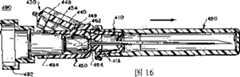
图16是图11另一实施例的横截面图,其展示了针尖防护安全帽组件装在注射器上并且针套将针盖住时的样子。16 is a cross-sectional view of the alternative embodiment of FIG. 11 showing the needle tip shield assembly mounted on the syringe with the needle guard covering the needle.
详细描述A detailed description
采用本发明的针尖防护安全帽组件后,就可根本消除针在用后意外扎人的事情。为了防止意外扎人,本发明采用一个盖、帽或杯形件来盖住针尖或将针尖在使用后收在一个防护位中。After adopting the needle point protective safety cap assembly of the present invention, the accident of accidental needle sticking after use can be basically eliminated. To prevent accidental sticking, the present invention employs a cap, cap or cup to cover the needle point or store the needle point in a protective position after use.
针尖的顶盖上有一个孔,这样顶盖可在注射前沿着针头滑到远离针尖的收缩位,在注射后再沿着针头滑回盖住针尖。只要针尖一注射完并回到顶盖中,就将顶盖旋转或扭转,这样针尖就不会从顶盖上的孔再冒出来。顶盖的端头形成一个容腔,以固定针头的端部,防止针穿过端壁中的孔再冒出来。The needle tip cap has a hole so that the cap can be slid along the needle to a retracted position away from the needle tip before injection, and then slid back along the needle to cover the needle tip after injection. As soon as the needle tip is injected and back into the cap, turn or twist the cap so that the needle tip does not come out of the hole in the cap again. The end of the cap forms a cavity to hold the end of the needle and prevent the needle from reemerging through the hole in the end wall.
针尖顶盖通常设计成能与一般针套相接的结构,这样,针尖防护安全帽组件在针套安装以及针头售出前装好。因此在出售针头时,针尖顶盖已缩到远离针尖的位置而针套则以通常的形式将针套住。The needle point top cover is usually designed to be connected to a common needle cover, so that the needle point protective safety cap assembly is assembled before the needle cover is installed and the needle is sold. The needle is therefore sold with the tip cap retracted away from the needle tip and the needle guard covering the needle in the usual fashion.
在准备注射的过程中,将针套去掉,然后就能用注射器以通常的方式来注射。注射后针尖顶盖沿着整个针头滑过、旋转以防止针尖再冒出来。In preparation for the injection, the needle cover is removed and the syringe can be used to inject in the usual way. After injection, the needle tip cover slides and rotates along the entire needle to prevent the needle tip from coming out again.
为了方便针尖顶盖的旋转、为了有一个装置使顶盖沿着针更加方便地滑动、也为了方便与针头毂或注射器的连接,针尖防护安全帽组件还可有一个可折叠伸长部分或称可折伸的构架连接在针尖顶盖上。该可折叠伸长部分或称可折伸构架可转而与一个连接件相连,而连接件适用于以不可拆的形式与针头毂相连。针头毂再转而预装在注射器上,或者在注射或从病人抽取体液前将注射器与针头毂相接。In order to facilitate the rotation of the needle tip cap, in order to have a mechanism to make the cap slide along the needle more conveniently, and to facilitate the connection with the needle hub or syringe, the needle tip shield assembly can also have a foldable extension or extension. The collapsible frame is attached to the tip top cover. The collapsible elongate portion or collapsible frame is in turn connected to a connector adapted to be non-detachably connected to the needle hub. The needle hub is in turn preloaded on the syringe, or the syringe is attached to the needle hub prior to injecting or withdrawing bodily fluids from the patient.
为了有助于将针尖顶盖保持在针头毂上,优选实施例中加入了一个环形凹槽,其与针头毂上的环形圈相互啮合。To help retain the tip cap on the needle hub, the preferred embodiment incorporates an annular groove which interengages with an annular ring on the needle hub.
在注射前去掉针套的过程中,构架通常与连接件一起将针头顶盖保持在远离针尖的收缩位。优选实施例中,连接件上的一个突起部与构架上的一个槽相接,在操作针头护罩时,突起部的增大部分卡进槽内。注射后,手动或手推构架使针尖顶盖松开、滑向针尖并最终盖住针尖。During removal of the needle shield prior to injection, the frame, usually together with the connector, holds the needle cap in a retracted position away from the needle tip. In a preferred embodiment, a protrusion on the connector engages a slot in the frame, and the enlarged portion of the protrusion snaps into the slot when the needle shield is operated. After injection, the needle tip cap is released by hand or by pushing the frame, slides towards the needle tip, and finally caps the needle tip.
将针尖收到顶盖内后,对应于构架上的推动会有一个旋转。当针尖位于顶盖中时,如果继续推动构架,会使顶盖旋转。旋转后的顶盖通过将针尖保持在顶盖端壁的容腔中来防止针尖从盖孔中再冒出来。After receiving the needle tip into the top cap, there is a rotation corresponding to the push on the frame. When the needle tip is in the cap, further pushing on the frame will cause the cap to rotate. The rotated top cap prevents the needle tip from re-emerging from the cap hole by keeping the needle tip in the cavity of the top cap end wall.
为了进一步将顶盖保持在旋转位上,通常会将构架锁定或固定到针杆上。将构架固定起来还可防止构架折叠起来以及顶盖沿着针杆滑回。这样就能进一步确保针尖不会再冒出。To further hold the top cap in the swivel position, the frame is usually locked or secured to the needle bar. Securing the frame also prevents the frame from collapsing and the top cover from sliding back along the needle bar. This can further ensure that the needle tip will not pop out again.
本优选实施例的安装Installation of the preferred embodiment
本发明的针尖防护安全帽组件100可通过一个单一的塑料件铸模加工出来以增加可靠性并降低加工和安装成本。尽管并非必须,但本发明的优选实施例就是采用单体的铸模塑料件。The needle tip shielding
本发明的设计是在使用针头前就完全装好,通常是在销售前就已装在针头上或注射器上。图1-5中的箭头显示的是该优选实施例的安装步骤。The present invention is designed to be completely assembled on the needle prior to use, usually on the needle or syringe prior to sale. The arrows in Figures 1-5 show the installation steps of this preferred embodiment.
为了装好优选实施例中的针尖防护安全帽组件,必须将注射器的连接件和针尖顶盖旋转到接收针头的位置。注射器连接件与构架柔性连接。为此,将注射器连接件或杯座150相对于构架130旋转约90度,这样针头就能沿着与伸开的构架130大致平行的方向穿过注射器连接件150。In order to assemble the needle tip shielding safety cap assembly of the preferred embodiment, the syringe adapter and needle point cap must be rotated into position to receive the needle. The syringe connector is flexibly connected to the frame. To do this, the syringe connector or
下一步,将一个与针尖顶盖110柔性连接的盖子(或称封闭件)118旋转后塞住或封住顶盖110。为了有助于将盖子保持在顶盖上,将盖子上的环形圈182与顶盖上的环形槽184啮合;圈和槽的横截面逐渐收缩从而使啮合更加容易,但这也使得圈和槽很难分开。In the next step, a cap (or closure) 118 flexibly connected to the
然后旋转与构架130柔性连接的封闭顶盖110,从而使针头穿过顶盖上的孔和杯座(即注射器连接件)150上的孔。The
当顶盖处于收住针的位置时,构架或伸展段130开始在两段之间的柔性部分折叠或弯折,然后顶盖110沿着针杆滑离针尖。为了有利于上述操作,也为了在插入针头之前更好地固定杯座,将一个针套300置于顶盖110上从而可更方便操纵顶盖110。When the cap is in the needle-receiving position, the frame or
当顶盖110在针杆上滑动时,构架或可折伸部分130继续弯折。当顶盖紧靠在或与针头毂或注射器接触时,构架130与杯座(即注射器连接件)150一起可松开地将顶盖固定住。优选实施例中,注射器连接件上一个头部增大的突起192穿过构架上的狭缝194。突起上头部增大的尺寸在设计上要求在构架上施加适当的力就能使头部卡入狭缝。As the
针套300在将顶盖110滑下针杆时,也被安装上去用于销售。为了将针的护罩固定在针头毂上,优选实施例中在连接件的内面采用了环形槽186,它与针管上相应的环形圈206接合。环和槽的横截面呈锥形,从而使啮合更为容易,但这也使得环和槽很难分开。虽然,用户可手动将构架松开,但注射前将针套300去掉时,不要动固定好的顶盖110。The needle guard 300 is also installed for sale when the
图1-10的优选实施例Preferred embodiment of Figures 1-10
图1-10展示了本发明针尖防护安全帽组件100的一个实施例。其优选采用一个单体塑料件来形成针尖防护安全帽组。图1和2所描述的是本优选针尖防护安全帽组从模子上取下来后两个不同侧面的样子。图3-10则展示了这个优选实施例准备使用时以及与注射器在实际使用时的样子。1-10 illustrate one embodiment of a needle tip shielding
回到图1和2,针尖防护组件100包括针尖顶盖(或称针尖帽或者杯形件或者是用来盖住针尖的针尖遮盖装置)110。顶盖110的形状为具有圆周壁的伸长件112。伸长件112的一端开口而另一端则几乎由底壁(或称端壁)116封上。Referring back to FIGS. 1 and 2 , the needle
在目前图1和2这个优选实施例中,顶盖110的底壁116上的孔(或称眼)114可使针头从中穿过。孔114位于底壁的偏心位置,而容腔126则占据了剩余的大部分壁面。一个杆臂(或称旋转装置)120与顶盖相连,当推动时,可使顶盖110相对针尖旋转从而防止针尖穿过孔114。In the presently preferred embodiment of FIGS. 1 and 2, a hole (or eye) 114 in the
图1和2还展示了盖子(或称封闭件或顶壁或)118,其可绕顶盖与盖子之间的连接部分旋转从而将顶盖110封闭。盖子(或称封闭装置)118上有一个孔(或称眼)122,可使针从中穿过。本实施例中,盖子(或称针杆啮合装置)118作为杠杆的支点与针头啮合。当针头穿过盖子上的孔122但未穿过底壁上的孔114时,盖子118与针头啮合并为顶盖的旋转提供一个支点。1 and 2 also show a cover (or closure or top wall or) 118 that is rotatable around the connection between the top cover and the cover to close the
在图1和2所示的实施例中,针尖防护安全帽组件100应适于同针头毂或注射器相连。顶盖110与可折伸构架(或称可折部件或可折伸段)130相连,可折伸构架再与杯座150相连。杯座150用来将针尖防护安全组件与针头毂或注射器相连。在本优选实施例中,顶盖110与可折伸构架130之间采用直接连接的形式。In the embodiment shown in Figures 1 and 2, the needle
杯座150具有圆周壁152和底壁154。底壁154具有针从中穿过的孔156。在该特例中,设有板条158,其用来限定圆周壁152的内侧靠近底壁154处的通道,从而可使杯座150更为容易地连接到针头毂上。本实施例中还包括一对连接臂160,从杯座150靠近底壁154处延伸出来。连接臂160用来将杯座150连接在可折伸构架130上。连接臂160与可折伸构架130是柔性连接。
优选实施例中的杯座150具有一个环形槽186与针头毂上相对的环形圈206接合。圈和槽的横截面呈锥形,从而使其接合更为容易,但分开很难。该优选实施例进一步包括一个长槽188,其与针管上相应的长凸起208相接合从而使针的护套能确定地旋转到与针孔220对齐的位置。The
在目前这个优选实施例中,可折伸构架130有许多用处。其可用来将杯座(即注射器连接件)150与针尖顶盖110相连,并可用来可松开地将顶盖110固定在针尖的远端。其还可用来将针尖顶盖110滑下针杆,并有助于顶盖110围着针尖旋转。此外,其还有助于保持针尖顶盖110的旋转位。In the presently preferred embodiment, the
如图1和2所示,可折伸段130,可包括一个叉骨(wishbone)形段132和一个下部段140。叉骨形段132具有两个臂134和一个座136。叉骨形段的臂134与杯座的连接臂160柔性连接。下部段140具有一个上端142和一个下端144。叉骨形段的座136与下部段140的上端142柔性相连。下部段的下端144与顶盖110柔性相连。有两个夹紧件148安装在下部段140上。叉骨形段132形成一个开口或称一个装置,当可折伸构架130弯折时,夹紧件148可从中穿过。这里还有一个装置,当可折伸构架130折起时,可使连接件上的突起192与狭缝194接合,这一点将在下面作更全面的描述。对此图6所示更为清楚。As shown in FIGS. 1 and 2 , the
图2还展示了压力平台146,其最终与杆臂120接触并使顶盖110产生旋转。图8和图9从最佳的角度展示了顶盖110绕针尖旋转的情景,这一点将在后面作全面的讨论。FIG. 2 also shows the
图2还展示了一对突出的夹紧件148,其从下部段140伸出,用作防护位锁定装置。针头在使用完后,夹紧件148用作一个将可折伸构架130固定在针杆上的装置。将可折伸构架130固定在针杆上可保证顶盖110保持在旋转位或扭转位,还可使顶盖110保持在防护位,这样顶盖110不会滑回到针杆上,将针尖暴露出来。Figure 2 also shows a pair of protruding
图9所示为夹紧件148与针杆啮合并将可折伸构架130固定在针杆上的情景。图10是针杆穿过夹紧件的横截面图,其示意出夹紧件与针杆啮合的情况。FIG. 9 shows the clamping
图3展示了杯座150是如何旋转从而为针头穿过杯座150以及为杯座150与注射器相连作准备的。板条158作为一个装置,在注射器与杯座中的针相连或分开时,可用来对针头进行定向并防止针在杯座中旋转。杯座(或称注射器连接件)150还具有一个头部增大了的突起192。突起可拆地与下部段140中的狭缝194啮合,从而当可折伸构架130如图6和图7弯折时,提供一个锁定装置。FIG. 3 shows how the
图3还展示了盖子118如何旋转并使顶盖110封闭形成图4所示腔128的情景。在本优选实施例中,盖子118上的孔(或称眼)122有一个部分倾斜的边124。部分倾斜的边124可使顶盖110如图9所示的那样更为容易地绕针尖旋转。FIG. 3 also shows how the
在图3所示优选实施例中,顶盖110具有一个紧靠着孔(或称眼)114的容腔126。其在顶盖110绕针尖旋转后,通过将针尖束缚住而有助于防止针尖从孔114意外地再次冒出。In the preferred embodiment shown in FIG. 3 , the
图4描述了杯座150旋转后的情况,并展示了针头插入的方向从而为针尖防护安全帽组件100与注射器相连作准备。图4还描述了封闭了的顶盖110中的腔128。在本优选实施例中腔128不仅将针尖盖住,还可收集从针尖流出的流体。FIG. 4 depicts the situation after the
图4中封闭了的顶盖110旁边的箭头指示出封闭了的顶盖110的旋转方向从而为针尖防护安全帽100与注射器的连接作准备。杯座150以及封闭了的顶盖110的旋转使得针头可穿过两者,从而为针尖防护安全帽组件100与注射器的连接作好准备。The arrow next to the
图5描述了针尖防护安全帽组件100与注射器相接从而为接收针套300作准备的情况。尽管在本优选实施例中,其是连接在针头毂204上,但其也可连接在针筒202上。FIG. 5 depicts the needle tip shielding
如图5所示,当装上针尖防护安全帽组件并为针套300的使用做好准备后,可折伸构架130开始弯折。图5还展示了可折伸构架130弯折时,其中一个夹紧件148将如何从叉骨形段132的臂134之间伸出的情景。As shown in FIG. 5 , when the needle tip protection safety cap assembly is installed and the needle sheath 300 is ready for use, the
图6展示了可折伸构架130折叠或弯折后,其中一个夹紧件148从叉骨形段132的臂134之间伸出的情况。从图6可清楚地看出,当可折伸构架130弯折后,两个夹紧件148都会从叉骨形段132的臂134之间伸出。FIG. 6 shows a state where one of the clamping
图5还描述了杯座150的突起192以及可折伸构架的狭缝194在针套300使用之前的情况。叉骨形段132的臂可使突起192与狭缝194啮合。FIG. 5 also depicts the
从图6可清楚地看出,顶盖110适于接收针套300从而防止针在使用前受到污染。在本优选实施例中,盖子118与杯座150的底壁154邻接以防止针受到污染。图6中所描述的带有针尖防护安全帽组件100并装好了针套300的注射器,是用户在使用前拿到的样子。用户在使用注射器时,只需将针套去掉然后按着图7所描述的一般的使用方式来使用注射器即可。连接件上的突起192以及可折伸构架的狭缝194可在针套300被去掉的过程中防止针尖帽110从针杆滑下。As is clear from Figure 6, the
使用后,用户只需用手指推已弯折了的可折伸构架130从而将突起192增大了的头部从狭缝194推出。突起上增大了的头部穿过狭缝时,会给用户提供一个触觉反馈信息,即针头的护罩已经启用,同时也告诉用户要施加一个足够力使头部穿过狭缝,这样可保证用户的指头有足够的冲力完全启动针头护罩。After use, the user only needs to push the bent and
然后,用户继续推可折伸构架130,使顶盖110如图8所示滑过针头的长度。在本优选实施例中,当顶盖110靠近针尖时,压力平台146接近并最终与杆臂120接触。接触后,继续推可折伸构架130从而将力加到杆臂120上。大约在接触的同时,针尖从孔114出来进到腔128中。在针尖从孔114出来后,相应于杆臂120的推力,顶盖110绕孔122旋转并因此绕着针尖旋转。图9展示了旋转后的顶盖110。The user then continues to push the
对应于用户的推力,当可折伸构架130接近针杆时,夹紧件148与针头啮合并将针头绕住,这样可折伸构架就夹在图9所示的位置。这就提供了一种装置,它通过保持压力平台146与杆臂120的接合从而保持或将顶盖110固定于其相对于针尖旋转后的位置,并进而防止针尖从孔114再冒出来。它还可用来提供一种装置,该装置可防止可折伸构架130弯折并防止顶盖110沿着针杆向上回滑而将针尖露出。因此,夹紧件148可用作将针尖顶盖110固定在针头的防护位置的装置。夹紧件在与针杆啮合时,还可给用户提供额外的触觉反馈信息。Corresponding to the pushing force of the user, when the
此外,在图9所描述的优选实施例中,容腔126用来限制针尖并防止针尖从孔114再冒出来。该容腔还有助于收集从针尖流出来的流体从而使流体不会从顶盖中跑出。还有,为了方便同时也为了确保从顶盖110的底壁116上的孔114漏出来的过量流体被收集到起来,在准备处理时,将针套300置于顶盖110上。Additionally, in the preferred embodiment depicted in FIG. 9 ,
图11-16所示另一实施例的说明Description of another embodiment shown in Figures 11-16
该实施例中的针尖防护安全帽组件400也由一个单一塑料件铸模加工出来以增加可靠性并降低生产和安装成本。The needle
为了安装该实施例的针尖防护安全帽组件,注射器连接件和针尖顶盖必须旋转到准备收容针头的位置。注射器连接件和构架之间为柔性连接。为此,将注射器连接件即杯座450相对于构架430旋转约90度,这样针头就能沿着与伸开的构架430大致平行的方向穿过注射器连接件450。In order to install the needle tip shielding safety cap assembly of this embodiment, the syringe adapter and needle tip cap must be rotated into a position ready to receive the needle. There is a flexible connection between the syringe connector and the frame. To do this, the syringe connector or
下一步,将一个与针尖顶盖410柔性连接的盖子(或称封闭件)418旋转后塞住或封住顶盖410。然后旋转与构架430柔性连接且已被封上的顶盖,从而使针头能够穿过顶盖上的孔和杯座450上的孔。当顶盖处于收容针头的位置时,构架(或称可折伸段)430开始在两段之间的柔性部分折叠或弯折,然后将顶盖410沿着针杆滑离针尖。为了有利于上述操作,也为了在插入针头之前更好地固定杯形件,将一个针套480置于顶盖410上从而更便于操纵顶盖410。In the next step, a cover (or closure) 418 flexibly connected to the needle point
当顶盖410在针杆上滑动时,构架(或称可折伸部分)430继续弯折。当顶盖紧靠在或与针头毂或注射器接触时,通过用针套480使顶盖410沿针杆滑下,构架430将与注射器连接件450一起可松开地将顶盖固定住。准备销售时也需安装针套。虽然,用户可启动顶盖将构架松开,但注射前将针套480去掉时,不要动固定好的顶盖410。When the
图11和12所示为该实施例从模子上取下来后的两个不同侧面。图13-16则描述了本优选实施例准备与注射器一起使用时的样子。Figures 11 and 12 show two different sides of this embodiment after it has been removed from the mould. Figures 13-16 depict the preferred embodiment ready for use with a syringe.
回到图11和12,针尖防护组件400包括针尖顶盖(或称针尖帽或者杯形件或者是用来盖住针尖的针尖遮盖装置)410。顶盖410的形状为具有圆周壁的伸长件412。伸长件412的一端开口而另一端则几乎由底壁(或称端壁)416封上。Referring back to FIGS. 11 and 12 , the needle
在图11和12的实施例中,针可从顶盖410的底壁416上的孔(或称眼)414穿过。一个杆臂(或称旋转装置)420与顶盖相连,当推动杆臂时,可使顶盖410相对针尖旋转从而防止针尖从孔414穿过。In the embodiment of FIGS. 11 and 12 , the needle can pass through a hole (or eye) 414 in a
图11和12还展示了盖子(或称封闭件或顶壁)118,其可绕顶盖与盖子之间的连接部分旋转从而将顶盖帽410封闭。盖子418上有一个孔(或称眼)422,可使针头从中穿过。在该实施例中,盖子(或称针杆啮合装置)418作为杠杆的支点与针头啮合。当针头穿过盖子上的孔422但未穿过底壁上的孔414时,盖子418与针头啮合并为顶盖的旋转提供一个支点。FIGS. 11 and 12 also show a cover (or closure or top wall) 118 that is rotatable around the connection between the top cover and the cover to close the
顶盖410与可折伸构架(或称可折部件或可折伸段)430相连,可折伸构架再与注射器连接件即杯座450相连。杯座450可用来将针尖防护安全组件与针头毂或注射器相连。在该实施例中,顶盖410与可折伸构架部件430之间采用直接连接的形式。The
杯座450具有圆周壁452和底壁454。底壁454具有可容许针头从中穿过的孔456。在该特例中,设有板条458,用来限定圆周壁452内侧靠近底壁454处的通道,从而可使杯座450更为容易地连接到针头毂上。本实施例中还包括一个连接臂460,它从杯座450靠近底壁454的地方延伸。连接臂460用来将杯座450连接在可折伸构架430上。连接臂460与可折伸构架430为柔性连接。
在该实施例中,可折伸构架430有许多用处。其可用来将杯座450与针尖顶盖410相连,并可用来可松开地将顶盖410固定在针尖的远端。其还可用来使针尖顶盖410滑下针杆,并有助于顶盖410绕着针尖旋转。此外,其还有助于保持针尖顶盖410的旋转位置。In this embodiment, the
如图11和12所示,可折伸构架430可包括一个叉骨形段432和一个下部段440。叉骨形段432具有两个臂434和一个座436。叉骨形段的臂434与杯座的连接臂460柔性连接。下部段440具有一个上端442和一个下端444。叉骨形段的座436与下部段440的上端442柔性相连。下部段的下端444与顶盖410柔性相连。有两个突出的夹紧件448安装在下部段440上。叉骨形段432形成了一个开口或称一个装置,当可折伸构架430弯折时,夹紧件448可从中穿过。As shown in FIGS. 11 and 12 , the
图12还展示了一个压力平台446,其最终与杆臂420接触并使顶盖410产生旋转。压力平台446与锁定面(或称锁定边)449相邻。锁定面449用来在可折伸构架折起时将可折伸构架430固定在杯座450上。锁定面449将在下面作更详细地讨论。FIG. 12 also shows a
图12还展示了一对突出的夹紧件448,其从下部段440伸出,用作防护位锁定装置。针头使用完后,夹紧件448用作一个将可折伸构架430固定在针杆上的装置。将可折伸构架430固定在针杆上可确保顶盖410保持在旋转位或扭转位,以及使顶盖410保持在防护位,这样顶盖410不会沿着针杆向上滑回,并将针尖暴露出来。Figure 12 also shows a pair of protruding
图13展示了杯座450是如何旋转从而为针头穿过杯座450以及与注射器相连作准备的。板条458作为一个装置,在注射器与杯座中的针头相连或分开时,可用来对针头进行定向并防止针头在杯座中旋转。杯座(或称注射器连接件)450还具有一个突起(或称锁定隆起)462。突起462可拆地与锁定面449啮合,从而当可折伸构架430如图16那样弯折时,提供一个锁定装置。Figure 13 shows how the
图13还展示了盖子418旋转封闭顶盖410并形成图14所示腔428的情况。在此实施例中,盖子418上的孔(或称眼)422有一个部分倾斜的边424。部分倾斜的边424可使顶盖410如图9所示的那样更为容易地绕针尖旋转。FIG. 13 also shows the
顶盖410在孔(或称眼)414四周具有一个环形沟426。其在顶盖410绕针尖旋转后,通过将针尖束缚从而有助于防止针尖从孔414意外地再次冒出。The
图14描述了杯座450旋转后的情况,并展示了针头插入的方向从而为针尖防护安全帽组件400与注射器相连作准备。图14还描述了封闭了的顶盖410中的腔428。在此实施例中该腔不仅可盖住针尖,还可收集从针尖流出的流体。FIG. 14 depicts the
图14中,在封闭了的顶盖410旁边的箭头指示出封闭了的顶盖410旋转的方向,旋转以后就为针尖防护安全帽组件400与注射器相连作好了准备。将杯座450以及封闭了的顶盖410旋转后可使针头穿过两者,从而为针尖防护安全帽组件400与注射器的连接作好准备。In Fig. 14, the arrow next to the closed
图15描述了针尖防护安全帽组件400与注射器490相接从而为接收针套480作准备的情况。尽管在此实施例中,所述组件是连接在针头毂494上,但其也可以连接在针筒492上,从而提供一个与注射器490相连的装置。FIG. 15 depicts needle tip shielding
如图15所示,当装上针尖防护安全帽组件400并为针套480的使用做好准备后,可折伸构架430开始弯折。图15还展示了可折伸构架430弯折时,其中一个夹紧件448将如何从叉骨形段432的臂434之间伸出的情景。图16展示了可折伸构架430折叠或弯折后,其中一个夹紧件448从叉骨形段432的臂434之间伸出的情况。从图16可清楚地看出,当可折伸构架430弯折后,两个夹紧件448都会从叉骨形段432的臂434之间伸出。As shown in FIG. 15 , when the needle tip protection
图15还描述了杯座450的突起(或称锁定隆起)462以及锁定面(或称锁定边)449在使用针套480之前的情况。杯座450上的突起462提供了一个面,可折珍构架430上的锁定边449与之接触,从而提供了一个可松开的锁定装置。叉骨形段的臂434可使突起462与锁定面449接触。图16还描述了针套将针盖住的时候,锁定面449与突起462啮合的情况。FIG. 15 also depicts the protrusion (or locking protrusion) 462 and the locking surface (or locking edge) 449 of the
从图16可清楚地看出,顶盖410适于接收针套480从而防止针头在使用前被污染。在此实施例中,盖子(或称顶壁)418与杯座450的底壁454邻接以防止针头被污染。图16中所描述的带有针尖防护安全帽组件400并装好针套480的注射器,是用户在使用前拿到样子。用户在使用注射器时,只需将针套去掉就能按照一般的方法来使用注射器。相互啮合的突起462和锁定面449可在针套480被去掉的过程中用来防止顶盖410从针杆滑下。As best seen in Figure 16, the
使用后,用户只需用手指推已弯折了的可折伸构架430从而将锁定面449从突起462移出即可。在该实施例中,当针尖帽410靠近针尖时,压力平台446接近并最终与杆臂420接触。接触后,继续推可折伸构架430从而将力加到杆臂420上。大约在接触的同时,针尖从孔414出来进到腔428中。在针尖从孔414出来后,对应于杆臂420的推力,顶盖410绕孔422旋转并因此绕着针尖旋转。After use, the user only needs to push the bent and
当可折伸构架430相应于用户的推动接近针杆时,夹紧件448与针啮合并将针围住,这样可折伸构架430就被夹持定位。并由此提供了一种装置,该装置通过保持压力平台446与杆臂420的接合从而将顶盖410保持或固定在相对于针尖旋转后的位置,并进而防止针尖从孔414再冒出来。其还可用来提供一种装置,该装置可防止可折伸构架430弯折并防止顶盖410沿着针杆向上回滑而将针尖露出。因此,夹紧件448提供了一种将针尖顶盖410固定在针的防护位置的装置。When the
环形沟426用来限制针尖并防止针尖从孔414再冒出来。该沟还有助于收集从针尖流出来的流体从而使流体不会轻易地从针尖帽跑出。还可优选使孔422紧紧围绕在针杆周围,这样容腔内的流体不会从孔422漏出。此外,为了方便同时也为了确保从顶盖410的底壁416上的孔414漏出来的过量流体被收集到起来,在准备处理时,针套480可置于顶盖410上。The annular groove 426 serves to confine the needle tip and prevent the needle tip from re-emerging from the
虽然仅公开了本发明的几个实施例,但是在不脱离本发明权利要求的基础上,还会有许多改进或其它实施例。Although only a few embodiments of the invention have been disclosed, there are many modifications and other embodiments without departing from the claims of the invention.
Claims (20)
Translated fromChineseApplications Claiming Priority (1)
| Application Number | Priority Date | Filing Date | Title |
|---|---|---|---|
| PCT/US1998/020176WO2000016832A1 (en) | 1998-09-23 | 1998-09-23 | Needle point guard safety cap assembly |
Publications (2)
| Publication Number | Publication Date |
|---|---|
| CN1355716A CN1355716A (en) | 2002-06-26 |
| CN1193804Ctrue CN1193804C (en) | 2005-03-23 |
Family
ID=22267941
Family Applications (1)
| Application Number | Title | Priority Date | Filing Date |
|---|---|---|---|
| CNB988142503AExpired - Fee RelatedCN1193804C (en) | 1998-09-23 | 1998-09-23 | Needle tip protection helmet assembly |
Country Status (3)
| Country | Link |
|---|---|
| CN (1) | CN1193804C (en) |
| AU (1) | AU9777598A (en) |
| WO (1) | WO2000016832A1 (en) |
Families Citing this family (23)
| Publication number | Priority date | Publication date | Assignee | Title |
|---|---|---|---|---|
| US7029461B2 (en) | 1999-11-04 | 2006-04-18 | Tyco Healthcare Group Lp | Safety shield for medical needles |
| US8226617B2 (en) | 1999-11-04 | 2012-07-24 | Tyco Healthcare Group Lp | Safety shield apparatus and mounting structure for use with medical needle devices |
| US7198618B2 (en) | 1999-11-04 | 2007-04-03 | Tyco Healthcare Group Lp | Safety shield for medical needles |
| PT1607115E (en) | 1999-11-18 | 2009-11-30 | Tyco Healthcare | Safety needle autosheath |
| WO2002070056A1 (en) | 2001-03-02 | 2002-09-12 | Sherwood Services Ag | Passive safety shield |
| DE60226954D1 (en)* | 2001-03-14 | 2008-07-17 | Tyco Healthcare | Protective device for medical needles |
| US7144389B2 (en) | 2001-03-14 | 2006-12-05 | Tyco Healthcare Group, Lp | Safety shield for medical needles |
| CN100536942C (en)* | 2001-09-13 | 2009-09-09 | 非洲风险技术(私人)有限公司 | Single-hand safety syringe |
| CA2422472A1 (en)* | 2002-03-19 | 2003-09-19 | Volker Niermann | Needle assembly |
| US6918891B2 (en) | 2002-03-21 | 2005-07-19 | Becton Dickinson Co | Safety device |
| US7553296B2 (en) | 2003-02-14 | 2009-06-30 | Tyco Healthcare Group Lp | Safety device with trigger mechanism |
| GB2398248A (en) | 2003-02-14 | 2004-08-18 | Scient Generics Ltd | Safety device with trigger mechanism |
| US8043300B2 (en) | 2005-07-05 | 2011-10-25 | Alcon, Inc. | Handpiece tip assembly |
| NZ555327A (en)* | 2007-05-21 | 2009-09-25 | Simcro Tech Ltd | An applicator which has a two stage interlock that protects from æneedle stickÆ injuries by covering the needle with a shield which also needs to be retracted before a dose can be administered |
| WO2009046560A2 (en)* | 2007-10-12 | 2009-04-16 | Otto Hess | Safety arrangement for the cannula of an invasive instrument |
| CN102139130A (en)* | 2010-01-29 | 2011-08-03 | 林铭田 | safety needle cover |
| JP7059251B2 (en) | 2016-08-01 | 2022-04-25 | ウェスト ファーマ サービシーズ イスラエル リミテッド | A spring that prevents the door from closing halfway |
| CA3038016C (en)* | 2016-09-27 | 2023-10-03 | Sanoculis Ltd. | Apparatus for tissue removal |
| IL251684B (en) | 2017-04-09 | 2019-01-31 | Tel Hashomer Medical Res Infrastructure & Services Ltd | Device and method for creating a canal in soft tissue |
| US11191316B2 (en) | 2017-04-26 | 2021-12-07 | Fend Corp. | Collapsible helmet |
| EP3630226A1 (en) | 2017-05-30 | 2020-04-08 | West Pharma. Services Il, Ltd. | Modular drive train for wearable injector |
| CN111065428B (en)* | 2017-05-30 | 2022-10-11 | 西医药服务以色列有限公司 | Needle shield for needle retraction |
| US11266792B2 (en) | 2019-10-28 | 2022-03-08 | FGC Holdings Limited | Single use safety needle guard |
Family Cites Families (7)
| Publication number | Priority date | Publication date | Assignee | Title |
|---|---|---|---|---|
| US4935013A (en)* | 1988-02-23 | 1990-06-19 | Habley Medical Technology Corporation | Collapsible needle cover |
| US4892521A (en)* | 1988-08-03 | 1990-01-09 | Lincoln Mills, Inc. | Protective cover for hypodermic needle |
| US5250031A (en)* | 1992-12-14 | 1993-10-05 | The George Washington University | Locking needle cover |
| US5549570A (en)* | 1993-01-27 | 1996-08-27 | Rogalsky; Alena | Medical needle unit |
| GB2283429B (en)* | 1993-11-04 | 1998-04-01 | David Howell Jenkins | A needle point protector |
| US5735827A (en)* | 1996-09-26 | 1998-04-07 | Becton, Dickinson And Company | Needle assembly having locking enclosure |
| US5814018A (en)* | 1997-06-20 | 1998-09-29 | Lawrence R. Koh | Needle point guard safety cap assembly |
- 1998
- 1998-09-23CNCNB988142503Apatent/CN1193804C/ennot_activeExpired - Fee Related
- 1998-09-23AUAU97775/98Apatent/AU9777598A/ennot_activeAbandoned
- 1998-09-23WOPCT/US1998/020176patent/WO2000016832A1/enactiveApplication Filing
Also Published As
| Publication number | Publication date |
|---|---|
| CN1355716A (en) | 2002-06-26 |
| WO2000016832A1 (en) | 2000-03-30 |
| AU9777598A (en) | 2000-04-10 |
Similar Documents
| Publication | Publication Date | Title |
|---|---|---|
| CN1193804C (en) | Needle tip protection helmet assembly | |
| US6015397A (en) | Needle point guard safety cap assembly | |
| KR101076349B1 (en) | Safety needle assembly | |
| JP5775931B2 (en) | Disposable collection device for body fluid | |
| CN1636607B (en) | Passive safety device for needle of blood collection set | |
| ES2330842T3 (en) | SAFETY PROTECTION FOR MEDICAL NEEDLES. | |
| US5814018A (en) | Needle point guard safety cap assembly | |
| ES2564497T3 (en) | Medication pen assembly with a needle safety guard that locks | |
| CN1202875C (en) | Automated Safety Sheath System for Syringes | |
| JP7343647B2 (en) | safety needle device | |
| BRPI0618093B1 (en) | NEEDLE PROTECTIVE MACHINE NEEDLE SET WITH ONE HAND | |
| JP2003310756A (en) | Needle assembly, blood collection set and method for covering the puncture end of needle cannula | |
| BR112013020087B1 (en) | SAFETY NEEDLE SET | |
| BRPI0518833B1 (en) | disposal and method for making a needle safe | |
| ES2848300T3 (en) | Injection aid item for use with an injection device and method of use | |
| CN1319023A (en) | Retractable needle medical device | |
| BRPI0510480B1 (en) | injection device | |
| BR112013000038A2 (en) | safety device for a pre-filled syringe and injection device | |
| JP4546533B2 (en) | Adapter for needle hub assembly | |
| ES2367987T3 (en) | SAFETY NEEDLE ASSEMBLY. | |
| CN1376076A (en) | Winged injection needle with needle cover | |
| ES2272675T3 (en) | FLUID COLLECTOR DEVICE. | |
| BR112019017220B1 (en) | NEEDLE PROTECTION DEVICE FOR A PRE-LOADED SYRINGE WITH NEEDLE ATTACHED AND PRE-LOADED SYRINGE WITH NEEDLE ATTACHED | |
| US20050015054A1 (en) | Syringe needle protecting cover | |
| JP4844259B2 (en) | Method for manufacturing a needle assembly |
Legal Events
| Date | Code | Title | Description |
|---|---|---|---|
| C10 | Entry into substantive examination | ||
| SE01 | Entry into force of request for substantive examination | ||
| C06 | Publication | ||
| PB01 | Publication | ||
| C14 | Grant of patent or utility model | ||
| GR01 | Patent grant | ||
| C17 | Cessation of patent right | ||
| CF01 | Termination of patent right due to non-payment of annual fee | Granted publication date:20050323 Termination date:20091023 |