CN1192050A - Semiconductor devices - Google Patents
Semiconductor devicesDownload PDFInfo
- Publication number
- CN1192050A CN1192050ACN97119558ACN97119558ACN1192050ACN 1192050 ACN1192050 ACN 1192050ACN 97119558 ACN97119558 ACN 97119558ACN 97119558 ACN97119558 ACN 97119558ACN 1192050 ACN1192050 ACN 1192050A
- Authority
- CN
- China
- Prior art keywords
- layer
- tungsten
- refractory metal
- semiconductor device
- liner
- Prior art date
- Legal status (The legal status is an assumption and is not a legal conclusion. Google has not performed a legal analysis and makes no representation as to the accuracy of the status listed.)
- Granted
Links
- 239000004065semiconductorSubstances0.000titleclaimsabstractdescription31
- 239000003870refractory metalSubstances0.000claimsdescription49
- 229910052751metalInorganic materials0.000claimsdescription31
- 239000002184metalSubstances0.000claimsdescription31
- 239000000956alloySubstances0.000claimsdescription30
- 229910045601alloyInorganic materials0.000claimsdescription29
- 125000006850spacer groupChemical group0.000claimsdescription3
- 239000010410layerSubstances0.000description99
- 238000000034methodMethods0.000description49
- 229910052721tungstenInorganic materials0.000description44
- WFKWXMTUELFFGS-UHFFFAOYSA-NtungstenChemical compound[W]WFKWXMTUELFFGS-UHFFFAOYSA-N0.000description43
- 239000010937tungstenSubstances0.000description43
- 239000010936titaniumSubstances0.000description40
- NRTOMJZYCJJWKI-UHFFFAOYSA-NTitanium nitrideChemical compound[Ti]#NNRTOMJZYCJJWKI-UHFFFAOYSA-N0.000description33
- 239000010949copperSubstances0.000description33
- 238000001465metallisationMethods0.000description31
- 239000000758substrateSubstances0.000description31
- 229910018182Al—CuInorganic materials0.000description27
- RYGMFSIKBFXOCR-UHFFFAOYSA-NCopperChemical compound[Cu]RYGMFSIKBFXOCR-UHFFFAOYSA-N0.000description27
- 229910052802copperInorganic materials0.000description27
- 238000005498polishingMethods0.000description27
- 238000004544sputter depositionMethods0.000description26
- 238000000151depositionMethods0.000description25
- 238000001020plasma etchingMethods0.000description21
- 229910052719titaniumInorganic materials0.000description21
- 230000008569processEffects0.000description17
- 238000005240physical vapour depositionMethods0.000description14
- 230000008021depositionEffects0.000description13
- XAGFODPZIPBFFR-UHFFFAOYSA-NaluminiumChemical compound[Al]XAGFODPZIPBFFR-UHFFFAOYSA-N0.000description11
- 230000004888barrier functionEffects0.000description10
- 238000009792diffusion processMethods0.000description10
- RTAQQCXQSZGOHL-UHFFFAOYSA-NTitaniumChemical compound[Ti]RTAQQCXQSZGOHL-UHFFFAOYSA-N0.000description9
- 229910052782aluminiumInorganic materials0.000description9
- 238000000576coating methodMethods0.000description9
- 239000004020conductorSubstances0.000description9
- 150000002739metalsChemical class0.000description9
- 239000000725suspensionSubstances0.000description9
- 239000004642PolyimideSubstances0.000description8
- 239000011248coating agentSubstances0.000description8
- 238000005516engineering processMethods0.000description8
- 229920001721polyimidePolymers0.000description8
- 239000002131composite materialSubstances0.000description7
- 238000011049fillingMethods0.000description7
- 239000007789gasSubstances0.000description7
- 239000000463materialSubstances0.000description7
- 230000004048modificationEffects0.000description7
- 238000012986modificationMethods0.000description7
- 238000001039wet etchingMethods0.000description7
- VYPSYNLAJGMNEJ-UHFFFAOYSA-NSilicium dioxideChemical compoundO=[Si]=OVYPSYNLAJGMNEJ-UHFFFAOYSA-N0.000description6
- 230000015572biosynthetic processEffects0.000description6
- 238000005530etchingMethods0.000description6
- 230000008020evaporationEffects0.000description6
- 238000001704evaporationMethods0.000description6
- VCJMYUPGQJHHFU-UHFFFAOYSA-Niron(3+);trinitrateChemical compound[Fe+3].[O-][N+]([O-])=O.[O-][N+]([O-])=O.[O-][N+]([O-])=OVCJMYUPGQJHHFU-UHFFFAOYSA-N0.000description6
- 238000001878scanning electron micrographMethods0.000description6
- 229910052715tantalumInorganic materials0.000description6
- 229910004298SiO 2Inorganic materials0.000description5
- XUIMIQQOPSSXEZ-UHFFFAOYSA-NSiliconChemical compound[Si]XUIMIQQOPSSXEZ-UHFFFAOYSA-N0.000description5
- PNEYBMLMFCGWSK-UHFFFAOYSA-Naluminium oxideInorganic materials[O-2].[O-2].[O-2].[Al+3].[Al+3]PNEYBMLMFCGWSK-UHFFFAOYSA-N0.000description5
- 239000010408filmSubstances0.000description5
- 238000004519manufacturing processMethods0.000description5
- 229910052710siliconInorganic materials0.000description5
- 239000010703siliconSubstances0.000description5
- -1aluminum and copperChemical class0.000description4
- 239000011651chromiumSubstances0.000description4
- 150000001875compoundsChemical class0.000description4
- 239000012212insulatorSubstances0.000description4
- 238000002161passivationMethods0.000description4
- 229920002120photoresistant polymerPolymers0.000description4
- 239000000843powderSubstances0.000description4
- 239000000126substanceSubstances0.000description4
- GUVRBAGPIYLISA-UHFFFAOYSA-Ntantalum atomChemical compound[Ta]GUVRBAGPIYLISA-UHFFFAOYSA-N0.000description4
- 239000010409thin filmSubstances0.000description4
- 229910000881Cu alloyInorganic materials0.000description3
- MHAJPDPJQMAIIY-UHFFFAOYSA-NHydrogen peroxideChemical compoundOOMHAJPDPJQMAIIY-UHFFFAOYSA-N0.000description3
- ZOKXTWBITQBERF-UHFFFAOYSA-NMolybdenumChemical compound[Mo]ZOKXTWBITQBERF-UHFFFAOYSA-N0.000description3
- 230000008901benefitEffects0.000description3
- 239000005380borophosphosilicate glassSubstances0.000description3
- 229910052804chromiumInorganic materials0.000description3
- 238000002474experimental methodMethods0.000description3
- 229910052750molybdenumInorganic materials0.000description3
- 239000011733molybdenumSubstances0.000description3
- 238000000059patterningMethods0.000description3
- 239000005360phosphosilicate glassSubstances0.000description3
- 238000000623plasma-assisted chemical vapour depositionMethods0.000description3
- 230000009467reductionEffects0.000description3
- 238000007789sealingMethods0.000description3
- 235000012239silicon dioxideNutrition0.000description3
- 239000000377silicon dioxideSubstances0.000description3
- 229910002058ternary alloyInorganic materials0.000description3
- 229910052723transition metalInorganic materials0.000description3
- 150000003624transition metalsChemical class0.000description3
- 229910000838Al alloyInorganic materials0.000description2
- XKRFYHLGVUSROY-UHFFFAOYSA-NArgonChemical compound[Ar]XKRFYHLGVUSROY-UHFFFAOYSA-N0.000description2
- VYZAMTAEIAYCRO-UHFFFAOYSA-NChromiumChemical compound[Cr]VYZAMTAEIAYCRO-UHFFFAOYSA-N0.000description2
- PXHVJJICTQNCMI-UHFFFAOYSA-NNickelChemical compound[Ni]PXHVJJICTQNCMI-UHFFFAOYSA-N0.000description2
- BLRPTPMANUNPDV-UHFFFAOYSA-NSilaneChemical compound[SiH4]BLRPTPMANUNPDV-UHFFFAOYSA-N0.000description2
- 229910001069Ti alloyInorganic materials0.000description2
- 229910010039TiAl3Inorganic materials0.000description2
- 238000005299abrasionMethods0.000description2
- 230000008859changeEffects0.000description2
- 239000000460chlorineSubstances0.000description2
- 229910052681coesiteInorganic materials0.000description2
- 230000007797corrosionEffects0.000description2
- 238000005260corrosionMethods0.000description2
- 229910052906cristobaliteInorganic materials0.000description2
- 230000003628erosive effectEffects0.000description2
- 239000011521glassSubstances0.000description2
- 239000001257hydrogenSubstances0.000description2
- 229910052739hydrogenInorganic materials0.000description2
- 238000009413insulationMethods0.000description2
- 239000011229interlayerSubstances0.000description2
- 238000007521mechanical polishing techniqueMethods0.000description2
- 239000000203mixtureSubstances0.000description2
- 239000011241protective layerSubstances0.000description2
- 239000002356single layerSubstances0.000description2
- 239000007787solidSubstances0.000description2
- 229910052682stishoviteInorganic materials0.000description2
- 229910052905tridymiteInorganic materials0.000description2
- IRPGOXJVTQTAAN-UHFFFAOYSA-N2,2,3,3,3-pentafluoropropanalChemical compoundFC(F)(F)C(F)(F)C=OIRPGOXJVTQTAAN-UHFFFAOYSA-N0.000description1
- KLZUFWVZNOTSEM-UHFFFAOYSA-KAluminum fluorideInorganic materialsF[Al](F)FKLZUFWVZNOTSEM-UHFFFAOYSA-K0.000description1
- JBRZTFJDHDCESZ-UHFFFAOYSA-NAsGaChemical compound[As]#[Ga]JBRZTFJDHDCESZ-UHFFFAOYSA-N0.000description1
- ZAMOUSCENKQFHK-UHFFFAOYSA-NChlorine atomChemical compound[Cl]ZAMOUSCENKQFHK-UHFFFAOYSA-N0.000description1
- 229910017758Cu-SiInorganic materials0.000description1
- 229910017931Cu—SiInorganic materials0.000description1
- YCKRFDGAMUMZLT-UHFFFAOYSA-NFluorine atomChemical compound[F]YCKRFDGAMUMZLT-UHFFFAOYSA-N0.000description1
- XPDWGBQVDMORPB-UHFFFAOYSA-NFluoroformChemical compoundFC(F)FXPDWGBQVDMORPB-UHFFFAOYSA-N0.000description1
- 229910001218Gallium arsenideInorganic materials0.000description1
- UFHFLCQGNIYNRP-UHFFFAOYSA-NHydrogenChemical compound[H][H]UFHFLCQGNIYNRP-UHFFFAOYSA-N0.000description1
- 229910002651NO3Inorganic materials0.000description1
- NHNBFGGVMKEFGY-UHFFFAOYSA-NNitrateChemical compound[O-][N+]([O-])=ONHNBFGGVMKEFGY-UHFFFAOYSA-N0.000description1
- 229910002668Pd-CuInorganic materials0.000description1
- 229910052581Si3N4Inorganic materials0.000description1
- JUZTWRXHHZRLED-UHFFFAOYSA-N[Si].[Cu].[Cu].[Cu].[Cu].[Cu]Chemical compound[Si].[Cu].[Cu].[Cu].[Cu].[Cu]JUZTWRXHHZRLED-UHFFFAOYSA-N0.000description1
- 239000002318adhesion promoterSubstances0.000description1
- WPPDFTBPZNZZRP-UHFFFAOYSA-Naluminum copperChemical compound[Al].[Cu]WPPDFTBPZNZZRP-UHFFFAOYSA-N0.000description1
- 229910052786argonInorganic materials0.000description1
- 125000004429atomChemical group0.000description1
- 230000009286beneficial effectEffects0.000description1
- 229910002056binary alloyInorganic materials0.000description1
- 239000006227byproductSubstances0.000description1
- 239000000919ceramicSubstances0.000description1
- 229910052801chlorineInorganic materials0.000description1
- 229910017052cobaltInorganic materials0.000description1
- 239000010941cobaltSubstances0.000description1
- GUTLYIVDDKVIGB-UHFFFAOYSA-Ncobalt atomChemical compound[Co]GUTLYIVDDKVIGB-UHFFFAOYSA-N0.000description1
- 229910021360copper silicideInorganic materials0.000description1
- SBYXRAKIOMOBFF-UHFFFAOYSA-Ncopper tungstenChemical compound[Cu].[W]SBYXRAKIOMOBFF-UHFFFAOYSA-N0.000description1
- 230000007547defectEffects0.000description1
- 230000005669field effectEffects0.000description1
- 239000011737fluorineSubstances0.000description1
- 229910052731fluorineInorganic materials0.000description1
- 125000001153fluoro groupChemical groupF*0.000description1
- 125000004435hydrogen atomChemical class[H]*0.000description1
- 238000003384imaging methodMethods0.000description1
- 238000011065in-situ storageMethods0.000description1
- 229910010272inorganic materialInorganic materials0.000description1
- 239000011147inorganic materialSubstances0.000description1
- 239000011810insulating materialSubstances0.000description1
- 230000010354integrationEffects0.000description1
- 150000002500ionsChemical class0.000description1
- 238000002955isolationMethods0.000description1
- 238000001755magnetron sputter depositionMethods0.000description1
- 229910052759nickelInorganic materials0.000description1
- 229910052758niobiumInorganic materials0.000description1
- 238000005121nitridingMethods0.000description1
- 229920003986novolacPolymers0.000description1
- 239000012044organic layerSubstances0.000description1
- 238000004806packaging method and processMethods0.000description1
- 239000002245particleSubstances0.000description1
- 229920000193polymethacrylatePolymers0.000description1
- 239000011148porous materialSubstances0.000description1
- 238000002360preparation methodMethods0.000description1
- 230000001737promoting effectEffects0.000description1
- 238000002310reflectometryMethods0.000description1
- 239000011819refractory materialSubstances0.000description1
- HQVNEWCFYHHQES-UHFFFAOYSA-Nsilicon nitrideChemical compoundN12[Si]34N5[Si]62N3[Si]51N64HQVNEWCFYHHQES-UHFFFAOYSA-N0.000description1
- WNUPENMBHHEARK-UHFFFAOYSA-Nsilicon tungstenChemical compound[Si].[W]WNUPENMBHHEARK-UHFFFAOYSA-N0.000description1
- 239000007779soft materialSubstances0.000description1
- 238000001179sorption measurementMethods0.000description1
- 239000012815thermoplastic materialSubstances0.000description1
Images


Classifications
- H—ELECTRICITY
- H01—ELECTRIC ELEMENTS
- H01L—SEMICONDUCTOR DEVICES NOT COVERED BY CLASS H10
- H01L21/00—Processes or apparatus adapted for the manufacture or treatment of semiconductor or solid state devices or of parts thereof
- H01L21/70—Manufacture or treatment of devices consisting of a plurality of solid state components formed in or on a common substrate or of parts thereof; Manufacture of integrated circuit devices or of parts thereof
- H01L21/71—Manufacture of specific parts of devices defined in group H01L21/70
- H01L21/768—Applying interconnections to be used for carrying current between separate components within a device comprising conductors and dielectrics
- H01L21/76838—Applying interconnections to be used for carrying current between separate components within a device comprising conductors and dielectrics characterised by the formation and the after-treatment of the conductors
- H01L21/76841—Barrier, adhesion or liner layers
- H01L21/76843—Barrier, adhesion or liner layers formed in openings in a dielectric
- H—ELECTRICITY
- H01—ELECTRIC ELEMENTS
- H01L—SEMICONDUCTOR DEVICES NOT COVERED BY CLASS H10
- H01L23/00—Details of semiconductor or other solid state devices
- H01L23/52—Arrangements for conducting electric current within the device in operation from one component to another, i.e. interconnections, e.g. wires, lead frames
- H01L23/522—Arrangements for conducting electric current within the device in operation from one component to another, i.e. interconnections, e.g. wires, lead frames including external interconnections consisting of a multilayer structure of conductive and insulating layers inseparably formed on the semiconductor body
- H—ELECTRICITY
- H01—ELECTRIC ELEMENTS
- H01L—SEMICONDUCTOR DEVICES NOT COVERED BY CLASS H10
- H01L21/00—Processes or apparatus adapted for the manufacture or treatment of semiconductor or solid state devices or of parts thereof
- H01L21/70—Manufacture or treatment of devices consisting of a plurality of solid state components formed in or on a common substrate or of parts thereof; Manufacture of integrated circuit devices or of parts thereof
- H01L21/71—Manufacture of specific parts of devices defined in group H01L21/70
- H01L21/768—Applying interconnections to be used for carrying current between separate components within a device comprising conductors and dielectrics
- H01L21/76801—Applying interconnections to be used for carrying current between separate components within a device comprising conductors and dielectrics characterised by the formation and the after-treatment of the dielectrics, e.g. smoothing
- H—ELECTRICITY
- H01—ELECTRIC ELEMENTS
- H01L—SEMICONDUCTOR DEVICES NOT COVERED BY CLASS H10
- H01L21/00—Processes or apparatus adapted for the manufacture or treatment of semiconductor or solid state devices or of parts thereof
- H01L21/70—Manufacture or treatment of devices consisting of a plurality of solid state components formed in or on a common substrate or of parts thereof; Manufacture of integrated circuit devices or of parts thereof
- H01L21/71—Manufacture of specific parts of devices defined in group H01L21/70
- H01L21/768—Applying interconnections to be used for carrying current between separate components within a device comprising conductors and dielectrics
- H01L21/76838—Applying interconnections to be used for carrying current between separate components within a device comprising conductors and dielectrics characterised by the formation and the after-treatment of the conductors
- H01L21/7684—Smoothing; Planarisation
- H—ELECTRICITY
- H01—ELECTRIC ELEMENTS
- H01L—SEMICONDUCTOR DEVICES NOT COVERED BY CLASS H10
- H01L21/00—Processes or apparatus adapted for the manufacture or treatment of semiconductor or solid state devices or of parts thereof
- H01L21/70—Manufacture or treatment of devices consisting of a plurality of solid state components formed in or on a common substrate or of parts thereof; Manufacture of integrated circuit devices or of parts thereof
- H01L21/71—Manufacture of specific parts of devices defined in group H01L21/70
- H01L21/768—Applying interconnections to be used for carrying current between separate components within a device comprising conductors and dielectrics
- H01L21/76838—Applying interconnections to be used for carrying current between separate components within a device comprising conductors and dielectrics characterised by the formation and the after-treatment of the conductors
- H01L21/76841—Barrier, adhesion or liner layers
- H01L21/76843—Barrier, adhesion or liner layers formed in openings in a dielectric
- H01L21/76847—Barrier, adhesion or liner layers formed in openings in a dielectric the layer being positioned within the main fill metal
- H—ELECTRICITY
- H01—ELECTRIC ELEMENTS
- H01L—SEMICONDUCTOR DEVICES NOT COVERED BY CLASS H10
- H01L21/00—Processes or apparatus adapted for the manufacture or treatment of semiconductor or solid state devices or of parts thereof
- H01L21/70—Manufacture or treatment of devices consisting of a plurality of solid state components formed in or on a common substrate or of parts thereof; Manufacture of integrated circuit devices or of parts thereof
- H01L21/71—Manufacture of specific parts of devices defined in group H01L21/70
- H01L21/768—Applying interconnections to be used for carrying current between separate components within a device comprising conductors and dielectrics
- H01L21/76838—Applying interconnections to be used for carrying current between separate components within a device comprising conductors and dielectrics characterised by the formation and the after-treatment of the conductors
- H01L21/76841—Barrier, adhesion or liner layers
- H01L21/76843—Barrier, adhesion or liner layers formed in openings in a dielectric
- H01L21/76849—Barrier, adhesion or liner layers formed in openings in a dielectric the layer being positioned on top of the main fill metal
- H—ELECTRICITY
- H01—ELECTRIC ELEMENTS
- H01L—SEMICONDUCTOR DEVICES NOT COVERED BY CLASS H10
- H01L21/00—Processes or apparatus adapted for the manufacture or treatment of semiconductor or solid state devices or of parts thereof
- H01L21/70—Manufacture or treatment of devices consisting of a plurality of solid state components formed in or on a common substrate or of parts thereof; Manufacture of integrated circuit devices or of parts thereof
- H01L21/71—Manufacture of specific parts of devices defined in group H01L21/70
- H01L21/768—Applying interconnections to be used for carrying current between separate components within a device comprising conductors and dielectrics
- H01L21/76838—Applying interconnections to be used for carrying current between separate components within a device comprising conductors and dielectrics characterised by the formation and the after-treatment of the conductors
- H01L21/76841—Barrier, adhesion or liner layers
- H01L21/7685—Barrier, adhesion or liner layers the layer covering a conductive structure
- H01L21/76852—Barrier, adhesion or liner layers the layer covering a conductive structure the layer also covering the sidewalls of the conductive structure
- H—ELECTRICITY
- H01—ELECTRIC ELEMENTS
- H01L—SEMICONDUCTOR DEVICES NOT COVERED BY CLASS H10
- H01L21/00—Processes or apparatus adapted for the manufacture or treatment of semiconductor or solid state devices or of parts thereof
- H01L21/70—Manufacture or treatment of devices consisting of a plurality of solid state components formed in or on a common substrate or of parts thereof; Manufacture of integrated circuit devices or of parts thereof
- H01L21/71—Manufacture of specific parts of devices defined in group H01L21/70
- H01L21/768—Applying interconnections to be used for carrying current between separate components within a device comprising conductors and dielectrics
- H01L21/76838—Applying interconnections to be used for carrying current between separate components within a device comprising conductors and dielectrics characterised by the formation and the after-treatment of the conductors
- H01L21/76877—Filling of holes, grooves or trenches, e.g. vias, with conductive material
- H—ELECTRICITY
- H01—ELECTRIC ELEMENTS
- H01L—SEMICONDUCTOR DEVICES NOT COVERED BY CLASS H10
- H01L23/00—Details of semiconductor or other solid state devices
- H01L23/48—Arrangements for conducting electric current to or from the solid state body in operation, e.g. leads, terminal arrangements ; Selection of materials therefor
- H01L23/488—Arrangements for conducting electric current to or from the solid state body in operation, e.g. leads, terminal arrangements ; Selection of materials therefor consisting of soldered or bonded constructions
- H01L23/498—Leads, i.e. metallisations or lead-frames on insulating substrates, e.g. chip carriers
- H01L23/49866—Leads, i.e. metallisations or lead-frames on insulating substrates, e.g. chip carriers characterised by the materials
- H—ELECTRICITY
- H01—ELECTRIC ELEMENTS
- H01L—SEMICONDUCTOR DEVICES NOT COVERED BY CLASS H10
- H01L23/00—Details of semiconductor or other solid state devices
- H01L23/52—Arrangements for conducting electric current within the device in operation from one component to another, i.e. interconnections, e.g. wires, lead frames
- H01L23/522—Arrangements for conducting electric current within the device in operation from one component to another, i.e. interconnections, e.g. wires, lead frames including external interconnections consisting of a multilayer structure of conductive and insulating layers inseparably formed on the semiconductor body
- H01L23/532—Arrangements for conducting electric current within the device in operation from one component to another, i.e. interconnections, e.g. wires, lead frames including external interconnections consisting of a multilayer structure of conductive and insulating layers inseparably formed on the semiconductor body characterised by the materials
- H01L23/53204—Conductive materials
- H01L23/53209—Conductive materials based on metals, e.g. alloys, metal silicides
- H01L23/53214—Conductive materials based on metals, e.g. alloys, metal silicides the principal metal being aluminium
- H01L23/53223—Additional layers associated with aluminium layers, e.g. adhesion, barrier, cladding layers
- H—ELECTRICITY
- H01—ELECTRIC ELEMENTS
- H01L—SEMICONDUCTOR DEVICES NOT COVERED BY CLASS H10
- H01L23/00—Details of semiconductor or other solid state devices
- H01L23/52—Arrangements for conducting electric current within the device in operation from one component to another, i.e. interconnections, e.g. wires, lead frames
- H01L23/522—Arrangements for conducting electric current within the device in operation from one component to another, i.e. interconnections, e.g. wires, lead frames including external interconnections consisting of a multilayer structure of conductive and insulating layers inseparably formed on the semiconductor body
- H01L23/532—Arrangements for conducting electric current within the device in operation from one component to another, i.e. interconnections, e.g. wires, lead frames including external interconnections consisting of a multilayer structure of conductive and insulating layers inseparably formed on the semiconductor body characterised by the materials
- H01L23/53204—Conductive materials
- H01L23/53209—Conductive materials based on metals, e.g. alloys, metal silicides
- H01L23/53228—Conductive materials based on metals, e.g. alloys, metal silicides the principal metal being copper
- H01L23/53233—Copper alloys
- H—ELECTRICITY
- H01—ELECTRIC ELEMENTS
- H01L—SEMICONDUCTOR DEVICES NOT COVERED BY CLASS H10
- H01L23/00—Details of semiconductor or other solid state devices
- H01L23/52—Arrangements for conducting electric current within the device in operation from one component to another, i.e. interconnections, e.g. wires, lead frames
- H01L23/522—Arrangements for conducting electric current within the device in operation from one component to another, i.e. interconnections, e.g. wires, lead frames including external interconnections consisting of a multilayer structure of conductive and insulating layers inseparably formed on the semiconductor body
- H01L23/532—Arrangements for conducting electric current within the device in operation from one component to another, i.e. interconnections, e.g. wires, lead frames including external interconnections consisting of a multilayer structure of conductive and insulating layers inseparably formed on the semiconductor body characterised by the materials
- H01L23/53204—Conductive materials
- H01L23/53209—Conductive materials based on metals, e.g. alloys, metal silicides
- H01L23/53228—Conductive materials based on metals, e.g. alloys, metal silicides the principal metal being copper
- H01L23/53238—Additional layers associated with copper layers, e.g. adhesion, barrier, cladding layers
- H—ELECTRICITY
- H01—ELECTRIC ELEMENTS
- H01L—SEMICONDUCTOR DEVICES NOT COVERED BY CLASS H10
- H01L2924/00—Indexing scheme for arrangements or methods for connecting or disconnecting semiconductor or solid-state bodies as covered by H01L24/00
- H01L2924/0001—Technical content checked by a classifier
- H01L2924/0002—Not covered by any one of groups H01L24/00, H01L24/00 and H01L2224/00
- H—ELECTRICITY
- H01—ELECTRIC ELEMENTS
- H01L—SEMICONDUCTOR DEVICES NOT COVERED BY CLASS H10
- H01L2924/00—Indexing scheme for arrangements or methods for connecting or disconnecting semiconductor or solid-state bodies as covered by H01L24/00
- H01L2924/095—Indexing scheme for arrangements or methods for connecting or disconnecting semiconductor or solid-state bodies as covered by H01L24/00 with a principal constituent of the material being a combination of two or more materials provided in the groups H01L2924/013 - H01L2924/0715
- H01L2924/097—Glass-ceramics, e.g. devitrified glass
- H01L2924/09701—Low temperature co-fired ceramic [LTCC]
- Y—GENERAL TAGGING OF NEW TECHNOLOGICAL DEVELOPMENTS; GENERAL TAGGING OF CROSS-SECTIONAL TECHNOLOGIES SPANNING OVER SEVERAL SECTIONS OF THE IPC; TECHNICAL SUBJECTS COVERED BY FORMER USPC CROSS-REFERENCE ART COLLECTIONS [XRACs] AND DIGESTS
- Y10—TECHNICAL SUBJECTS COVERED BY FORMER USPC
- Y10S—TECHNICAL SUBJECTS COVERED BY FORMER USPC CROSS-REFERENCE ART COLLECTIONS [XRACs] AND DIGESTS
- Y10S148/00—Metal treatment
- Y10S148/015—Capping layer
- Y—GENERAL TAGGING OF NEW TECHNOLOGICAL DEVELOPMENTS; GENERAL TAGGING OF CROSS-SECTIONAL TECHNOLOGIES SPANNING OVER SEVERAL SECTIONS OF THE IPC; TECHNICAL SUBJECTS COVERED BY FORMER USPC CROSS-REFERENCE ART COLLECTIONS [XRACs] AND DIGESTS
- Y10—TECHNICAL SUBJECTS COVERED BY FORMER USPC
- Y10S—TECHNICAL SUBJECTS COVERED BY FORMER USPC CROSS-REFERENCE ART COLLECTIONS [XRACs] AND DIGESTS
- Y10S257/00—Active solid-state devices, e.g. transistors, solid-state diodes
- Y10S257/915—Active solid-state devices, e.g. transistors, solid-state diodes with titanium nitride portion or region
- Y—GENERAL TAGGING OF NEW TECHNOLOGICAL DEVELOPMENTS; GENERAL TAGGING OF CROSS-SECTIONAL TECHNOLOGIES SPANNING OVER SEVERAL SECTIONS OF THE IPC; TECHNICAL SUBJECTS COVERED BY FORMER USPC CROSS-REFERENCE ART COLLECTIONS [XRACs] AND DIGESTS
- Y10—TECHNICAL SUBJECTS COVERED BY FORMER USPC
- Y10S—TECHNICAL SUBJECTS COVERED BY FORMER USPC CROSS-REFERENCE ART COLLECTIONS [XRACs] AND DIGESTS
- Y10S438/00—Semiconductor device manufacturing: process
- Y10S438/959—Mechanical polishing of wafer
Landscapes
- Engineering & Computer Science (AREA)
- Physics & Mathematics (AREA)
- Condensed Matter Physics & Semiconductors (AREA)
- General Physics & Mathematics (AREA)
- Computer Hardware Design (AREA)
- Microelectronics & Electronic Packaging (AREA)
- Power Engineering (AREA)
- Manufacturing & Machinery (AREA)
- Internal Circuitry In Semiconductor Integrated Circuit Devices (AREA)
- Physical Vapour Deposition (AREA)
- Electrodes Of Semiconductors (AREA)
Abstract
Translated fromChineseDescription
Translated fromChinese本发明一般涉及半导体器件,尤其涉及采用由难熔金属的组合来填充衬底上的缝或孔的低成本方法制备的半导体器件。本发明特别适用于亚微米电路的制作。The present invention relates generally to semiconductor devices, and more particularly to semiconductor devices prepared by low cost methods of filling slots or holes in a substrate with a combination of refractory metals. The invention is especially suitable for the fabrication of submicron circuits.
低阻金属,诸如铝和铜以及它们的二元或三元的合金已广泛用于半导体制作的细线互连。细线互连金属的典型例子包括AlxCuy,其中x与y之和等于1,且x与y都大于或等于0而又小于或等于1,三元合金,如Al-Pd-Cu、Al-Pd-Nb及Al-Cu-Si和其它以低阻金属为基的合金。如今要强调的是随着超大规模集成(VLSl)电路制作的线条宽度的尺寸按比例缩小,已经带来包括不适当的绝缘、电迁移及平面化方面的可靠性问题。Low-resistance metals, such as aluminum and copper, and their binary or ternary alloys have been widely used for thin-wire interconnects in semiconductor fabrication. Typical examples of fine-line interconnect metals include Alx Cuy , where the sum of x and y is equal to 1, and both x and y are greater than or equal to 0 and less than or equal to 1, ternary alloys such as Al-Pd-Cu, Al-Pd-Nb and Al-Cu-Si and other alloys based on low resistance metals. Today it is emphasized that the scaling down of line width dimensions for very large scale integration (VLS1) circuit fabrication has brought about reliability issues including inadequate isolation, electromigration, and planarization.
Ahn等人在lBM技术公开公报((Vol、33,No.5,Oct,1990,pp.217-218)上披露了用WF6和SiF4的含氢混合物选择性淀积制造包覆以钨的铜导体与通孔。密封了的互连线,像Ahn等人做的那样,具有很高的抗电迁移能力,并且选用晶粒尺寸小的钨膜,以减小反射率,因而增强光刻设备聚焦的能力与光刻胶的解象能力。但是,采用Ahn等人描述的低温方法所形成的钨层理应是富硅(如,3-4%)的,而且对铜不会是一种良好的扩散阻挡层,因为形成铜的硅化物将会恶化铜的电阻率。因此,在低温下用选择法难以淀积一层扩散阻挡层。况且,Ahn等人的技术依赖于环形在导线底部的形成,而通常这是由释放的湿气与WF6反应产生的。通常认为环形的出现是不可靠的。Ahn et al. disclosed in the 1BM Technical Publication Bulletin ((Vol, 33, No.5, Oct, 1990, pp.217-218) the selective deposition of a hydrogen-containing mixture of WF6 and SiF4 to make a clad tungsten Copper conductors and vias. Sealed interconnects, as done by Ahn et al., have high resistance to electromigration, and use a tungsten film with a small grain size to reduce reflectivity and thus enhance light The focusing ability of etching equipment and the resolution ability of photoresist. However, the tungsten layer formed by the low temperature method described by Ahn et al. is supposed to be silicon-rich (eg, 3-4%), and it will not be negative for copper. A good diffusion barrier layer, because the formation of copper silicide will deteriorate the resistivity of copper. Therefore, it is difficult to deposit a layer of diffusion barrier layer by selective method at low temperature. Moreover, the technology of Ahn et al. The formation of the bottom, which is usually produced by the reaction of released moisture with WF6. The appearance of rings is generally considered to be unreliable.
Dalton等人(VMIG Conference,June 12-13,1990,pp.289-292)指出,含SiH4与H2还原WF6的一种热壁CVD反应在铝或合金导体上形成选择的钨层,其结果在铝与钨的界面含有氟团,该氟团是WF6与铝的一种副产物,如反应式1所示:Dalton et al. (VMIG Conference, June 12-13, 1990, pp.289-292) pointed out that a hot wall CVD reaction containing SiH4 and H2 to reduce WF6 forms a selective tungsten layer on aluminum or alloy conductors, As a result, there is a fluorine group at the interface between aluminum and tungsten, which is a by-product of WF6 and aluminum, as shown in Reaction Formula 1:
Dalton披露了一种形式互连线的传统方案,这里,首先在一平整的表面上淀积铝,溅射一层TiW么覆盖其上(只是与传统不同的过程),然后,用光刻胶成象和显影,接着通过反应离子刻蚀(RIE)把该铝层刻成图案。再将所得到的结构覆盖一层钝化介质,如SiO2或聚酰亚胺,随后本身也经RIE刻成图案并且金属化,从而实现一种多层结构。图1引自Dalton报告,并示出通过传统工艺方式生产的多层器件在金属导线的局部的介质层中有缝,而且顶面很不平整。Dalton discloses a traditional scheme for forming interconnect lines, where aluminum is first deposited on a flat surface, a layer of TiW is sputtered to cover it (just a different process from the traditional one), and then, a photoresist is used to Imaging and development, followed by patterning the aluminum layer by reactive ion etching (RIE). The resulting structure is then covered with a passivating medium, such asSiO2 or polyimide, which is itself patterned and metallized by RIE to achieve a multilayer structure. Figure 1 is quoted from the Dalton report and shows that the multilayer device produced by the traditional process has seams in the local dielectric layer of the metal wires, and the top surface is very uneven.
采用RIE法很难实现介质的平整化。平整度部分取决于图形的密度,而且不平表面将导致后继金属化时产生搅炼问题。如果将RIE技术用于聚酰亚胺,当刻蚀线路直到聚酰亚胺表面时,因除去光刻胶的过程也会除去聚酰亚胺,所以,需要为以铝或铜为基的线路的顶面上除去光刻胶而设置一刻蚀阻挡层。任何含铜量高的铝或铜的合金的RIE都极为困难。包括金属RIE的传统工艺方法的严重缺点是随着几何尺寸的微细化势必增多因粒子缺陷而造成的大量的金属短路。It is difficult to achieve the planarization of the medium by the RIE method. Flatness depends in part on the density of the pattern, and an uneven surface will cause churning problems in subsequent metallization. If RIE technology is used for polyimide, when etching the circuit to the surface of polyimide, the process of removing photoresist will also remove polyimide, so it needs to be aluminum or copper-based circuit The photoresist is removed to form an etch stop layer on the top surface. RIE of any aluminum or copper alloy with a high copper content is extremely difficult. The serious disadvantage of the traditional process method including metal RIE is that a large number of metal short circuits caused by particle defects will inevitably increase with the miniaturization of the geometric size.
Brown等人的美国专利4,824,802披露了一种多层VLSI金属化结构的层间介质通路或接触孔的填充方法。详细地说,一种过渡金属,诸如钨或钼,通过CVD法或是选择地淀积在绝缘层的开孔中,或是非选择性地淀积在绝缘层的整个表面及开孔中,然后,将平整化保护层,把诸如偶氮苯醌酚醛型清漆、聚甲基丙烯酸酯、聚酰亚胺,或其它的热塑性的材料加到过渡金属的顶面上。通过刻蚀直至带保护层的过渡金属被整平的位置,从而得到平整了的结构。Brown等人的方法避免不了侵蚀金属及与刻蚀有关的其它问题,还不能用于平整化Al-Cu或别的软合金材料,因它们的性质不同于诸如钨与钼之类的较硬金属。因此,采用Brown等人的方法,难以完全填满通路及导线。US Patent No. 4,824,802 to Brown et al. discloses a method for filling interlayer dielectric vias or contact holes in a multilayer VLSI metallization structure. In detail, a transition metal such as tungsten or molybdenum is either selectively deposited in the openings of the insulating layer or non-selectively deposited on the entire surface of the insulating layer and in the openings by CVD, and then , to planarize the protective layer, add such as azoquinone novolac, polymethacrylate, polyimide, or other thermoplastic materials to the top surface of the transition metal. The leveled structure is obtained by etching up to the point where the transition metal with protective layer is leveled. The method of Brown et al. does not avoid attacking metals and other problems associated with etching, and cannot be used to planarize Al-Cu or other soft alloy materials because their properties are different from those of harder metals such as tungsten and molybdenum . Therefore, it is difficult to completely fill the vias and wires using the method of Brown et al.
Beyer等人的美国专利4,944,836披露了一种可用在衬底上产生共平面的金属/绝缘物膜的化学-机械抛光技术。尤其是,Beyer等人预料,可将底下的绝缘层刻出图形、淀积Al-Cu膜,然后采用化学-机械抛光技术,在这里用稀硝酸氧化铝粉悬浮液来机械研磨表面,除去Al-Cu。以该抛光混合物除去Al-Cu,势必应比除去底下的绝缘物有更高的速度。这样所得的结构就包含有由绝缘层平整化了的Al-Cu导线,而且在制造多层结构时能方便地添加后续的多层。US Patent 4,944,836 to Beyer et al. discloses a chemical-mechanical polishing technique that can be used to produce coplanar metal/insulator films on a substrate. In particular, Beyer et al. envisioned that the underlying insulating layer could be patterned, an Al-Cu film deposited, followed by chemical-mechanical polishing techniques, where dilute alumina nitrate suspensions were used to mechanically abrade the surface to remove Al. -Cu. The removal of Al-Cu with the polishing mixture must be performed at a higher rate than the removal of the underlying insulation. The resulting structure thus contains Al-Cu conductors planarized by the insulating layer, and subsequent multilayers can be easily added in the fabrication of multilayer structures.
Cote等人的美国专利US-4,956,313披露了一种通路填充与平整化技术,其中Al-Cu合金导线在衬底的第一钝化层的顶面上制成图形。这些导线又涂敷上第二钝化层,该层以掺杂的玻璃,诸如磷硅玻璃(PSG)或硼磷硅玻璃(BPSG)为好,它能与Al-Cu合金导线各外形适配,然后在第二钝化层上开出通路以露出导线,再用CVD法将钨加到第二钝化层的表面及通路中,Cote等人的报告指出,CVD钨适合于共形,又能填充通路而不会产生空隙。而后,该结构经磨料悬浮液抛光平整化。US-4,956,313 to Cote et al. discloses a via filling and planarization technique in which Al-Cu alloy wires are patterned on the top surface of a first passivation layer of a substrate. These wires are coated with a second passivation layer, which is preferably doped glass, such as phosphosilicate glass (PSG) or borophosphosilicate glass (BPSG), which can be adapted to the shape of Al-Cu alloy wires. , and then open a path on the second passivation layer to expose the wire, and then add tungsten to the surface and path of the second passivation layer by CVD. The report of Cote et al. pointed out that CVD tungsten is suitable for conformal, and Can fill vias without creating voids. The structure is then planarized by abrasive suspension polishing.
无论Beyer等人还是Cote等人都认为对低电阻率、软金属,如Al-Cu合金等予以抛光是不实际的。这是因为在悬浮液的作用下,这些材料势必表面受擦伤、被沾污及侵蚀。况且,按照Cote等人产生的平整化结构需用多道工艺步骤,会增加成本、降低生产率。Both Beyer et al. and Cote et al. believe that it is impractical to polish low-resistivity, soft metals, such as Al-Cu alloys. This is because the surfaces of these materials tend to be scratched, stained and eroded by the suspension. Moreover, the planarized structure produced according to Cote et al. requires multiple process steps, which will increase the cost and reduce the productivity.
Rossnagel等人在J.Vac.Sci.Technol.2:261(Mar/Apr.1991)披露了一种用以淀积薄膜的准直磁控溅射淀积技术,该技术与剥离刻制图形技术和孔的填充是兼容的。该技术也出现在美国专利4,824,544中,于此可参照结合。Rossnagel et al. disclosed a collimated magnetron sputtering deposition technique for depositing thin films in J.Vac.Sci.Technol.2: 261 (Mar/Apr.1991), which is similar to lift-off patterning technique Compatible with hole filling. This technique is also presented in US Patent 4,824,544, incorporated herein by reference.
Shiozaki等人在固态器件与材料的第19届会议文摘(Abstracts ofThe 19th Conference on solid state Devices and Materials)上披露了采用选择的钨淀积技术填充在高电阻率硬金属,如Mosix,上面的孔,并与软金属的密封无关。Shiozaki et al. disclosed in Abstracts of The 19th Conference on solid state Devices and Materials that a selective tungsten deposition technique is used to fill high-resistivity hard metals, such as Mosix , above holes, and has nothing to do with the sealing of soft metals.
因此,本发明的一个目的是提供一种采用在衬底上按亚微米级形成低成本、无侵蚀、耐磨损、抗电迁移的电导体的互连电路而制造的半导体器件。SUMMARY OF THE INVENTION It is therefore an object of the present invention to provide a semiconductor device fabricated using an interconnect circuit of low-cost, non-erosion, abrasion-resistant, electromigration-resistant electrical conductors formed on a substrate at the submicron scale.
上述目的可由本发明的半导体器件实现,该半导体器件包括一介质层、至少一个位于介质层中的具有侧壁和底部的、高宽比大的亚微米孔或线路,以及在该至少一个孔中或线路上的基本共形的衬垫,底部的衬垫厚度大于侧壁的衬垫厚度。The above object can be achieved by the semiconductor device of the present invention, which comprises a dielectric layer, at least one submicron hole or circuit with a sidewall and a bottom in the dielectric layer, and a large aspect ratio, and in the at least one hole Or a substantially conformal pad on a line, with a pad thickness on the bottom that is greater than that on the sidewalls.
本发明提供的另一种半导体器件具有一介质层、在介质层中的至少一个具有侧壁和底部的高宽比至少为2∶1的亚微米孔或线路,以及一个与孔和线路共形的衬垫,该衬垫的底部与侧壁的厚度比至少为4∶3。Another semiconductor device provided by the present invention has a dielectric layer, at least one submicron hole or line in the dielectric layer having a side wall and a bottom with an aspect ratio of at least 2:1, and a conformal hole and line A gasket having a base to sidewall thickness ratio of at least 4:3.
对于上述目的以及本发明的优点,参照附图从下面的本发明优选的实施例的详细描述中,将能得到更好的理解,其中:For above-mentioned object and advantage of the present invention, will be able to obtain better understanding from the detailed description of following preferred embodiment of the present invention with reference to accompanying drawing, wherein:
图1是表示顶面不平的现有技术半导体衬底的剖面侧视图;FIG. 1 is a sectional side view showing a prior art semiconductor substrate having an uneven top surface;
图2A到2E是说明本发明一种改变的半导体衬底的连续剖面侧视图;2A to 2E are sequential sectional side views illustrating a modified semiconductor substrate of the present invention;
图3A至3B是有器件的衬底的连续侧视剖面图,在刻制绝缘物图形之前,其上涂敷了待整平的绝缘物;Figures 3A to 3B are sequential side cross-sectional views of a substrate with a device on which an insulator to be leveled has been applied prior to insulator patterning;
图4A到4E是说明本发明的另一种改型的半导体衬底的连续剖面侧视图;4A to 4E are sequential sectional side views illustrating another modified semiconductor substrate of the present invention;
图5A至5E是说明本发明还有一种改型的半导体衬底的连续剖面侧视图;5A to 5E are sequential sectional side views illustrating still another modification of the semiconductor substrate of the present invention;
图6是用PVD淀积在通路中的衬垫的扫描电子显微照片(SEM);Figure 6 is a scanning electron micrograph (SEM) of a liner deposited in a via by PVD;
图7A和7B是说明本发明的再一种改型的半导体衬底的连续剖面侧视图;7A and 7B are sequential sectional side views illustrating still another modified semiconductor substrate of the present invention;
图8是举例的,多层镶嵌结构,其中PVD AlxCuy合金覆盖着CVD钨的剖面图;以及Figure 8 is an exemplary, multi-level damascene structure in which a PVDAlxCuy alloy is covered witha cross-sectional view of CVD tungsten; and
图9A和9B分别是化学-机械抛光之前与之后具有被钨覆盖的Al-Cu合金导线的结构剖面SEM的显微照片。9A and 9B are SEM micrographs of a cross-section of a structure with Al-Cu alloy wires covered with tungsten before and after chemical-mechanical polishing, respectively.
本发明一般涉及衬底上形成金属填充的通路及导体线的方法,而该通路及导体线包括软的低电阻率的金属,该软金属又覆盖着相当硬的难熔金属,能抗侵蚀、耐磨损以及抗电迁移,此外,该通路及导体线用涂敷在衬底上的介质层予以平整化。采用的PVD淀积技术,按图2A-E、图4A-E及图7A-B描述的工艺过程。可以创造出多种不同的新颖结构。应当理解为,这些技术与所得到的结构不应限于使用任何特定的衬底和介质盖层(例如,象图2A-E与5A-E所示的使用无机的与有机的多层组合,同样可用无机或有机绝缘材料的单层)。而且,本发明也不限于任何特殊铁金属组合;宁可说,本发明的目的是将能耐磨损、抗侵蚀及抗电迁移的难熔硬金属盖在低阻的软金属上。本发明尤其和使用铝与铜合金的电层系有关,因为已经发现采用PVD准直溅射能以可靠的大高宽比填充到亚微米通路和槽中,淀积出均匀共形的难熔金属衬垫材料涂覆层。该难熔金属衬垫在后续的过程中将用作铜的有效的扩散阻挡层。The present invention generally relates to methods of forming metal-filled vias and conductor lines on a substrate, the vias and conductor lines comprising a soft, low-resistivity metal covered with a relatively hard refractory metal, resistant to corrosion, Abrasion and electromigration resistance, in addition, the vias and conductor lines are planarized with a dielectric layer applied to the substrate. The PVD deposition technology adopted follows the process described in FIGS. 2A-E, 4A-E and 7A-B. Many different novel structures can be created. It should be understood that these techniques and resulting structures should not be limited to the use of any particular substrate and dielectric capping layer (e.g., the use of inorganic and organic multilayer combinations as shown in FIGS. 2A-E and 5A-E, as well A single layer of inorganic or organic insulating material can be used). Also, the invention is not limited to any particular combination of ferrous metals; rather, it is an object of the invention to cap a soft, low-resistance metal with a refractory hard metal that is resistant to wear, erosion, and electromigration. The present invention is particularly relevant to electrical layer systems using aluminum and copper alloys, since it has been found that collimated sputtering using PVD can reliably fill submicron vias and trenches with high aspect ratios, depositing uniform conformal refractory Metal backing material coating. This refractory metal liner will serve as an effective diffusion barrier for copper in subsequent processes.
参见图2A,首先,将衬底10涂敷一层介质,接着把介质层刻出图形。衬底10优选的是适于制造集成电路的硅、砷化镓,或其它材料。然而,该衬底10也可以是常用于封装半导体,与制造薄膜互连线的陶瓷、玻璃、或复合材料。该衬底10最好于其中形成了许多半导体器件,可包括场效应晶体管(FET)、双极晶体管、电阻,肖特基二极管,或类似器件。应该理解,图3A-B、4A-E、5A-E、7A-B、以及图8各个所示的衬底10可以有上面讨论过任何特征,再加上本技术领域公知的其它的任何特征。Referring to FIG. 2A, first, the
图2A所示的介质复合层,分别包括顶上和底下的无机介质层11和13,可以是二氧化硅(SiO2),氮化硅(Si3N4),或类似物,该无机物层11和13两者最好用等离子增强化学汽相淀积(PECVD)法淀积,在导电的衬底10上,90乇下,首先淀积SiO2,再制备对可动离子扩散起阻挡作用的Si3N4(0.075至0.1μm)。一较厚的有机介质层12,诸如聚酰亚胺之类,淀积在无机层11和13之间。也可以采用一种无机物介质,诸如SiO2、PSG或BPSG的,或有机物介质,诸如聚酰亚胺,并且可用众所周知的许多技术的任一种,诸如在氮化气氛中、溅射,或PECVD法生长一层单层,去替代由层11,12和13所形成的介质复合层。虽然,图2A-E和5A-E表示应用复合结构,而图3A-B、4A-E及7A-B表示运用单无机物的或介质层,但应理解,该介质层不限于本发明的实践,而且在本发明的实施中,可以采用所用的任何介质(如,无机或有机的)本身或组合。The dielectric composite layer shown in Fig. 2A comprises inorganic
图2A示出介质复合层中形成了的开口14,这样的开口可以是一通路或导线的槽。VLSI应用中,该衬底10或许有如图2A所示的数百到几千个开口14,最后,得到密集复杂的图形终归要在衬底上或之中互连成电路。最好采用增强反差的不刻(CEL)法,随后用多圆片装置利用CHF3和O2刻蚀槽或孔,刻蚀以适当的过腐蚀为佳,以确保该开口14有所要求的尺寸,并延伸到衬底10表面的接触点作为一通路柱塞的图形。至于导线图形,最好将介质层局部刻蚀到这样的深度,要比待采用的金属厚度大约高10%,刻蚀聚酰亚胺12时,以低温下的O2 RIE为佳。应该知道,如图2A-E、4A-E、5A-E及7A-B所指的开口14成形在本领域内都是熟知的,还可以用许多不同的技术产生。Figure 2A shows an
如图3A和3B所示,若开始衬底10其上有一形成的器件(与图2A所示的不带向上凸出的器件的平整的衬底10相反),制造成开口22之前,首先要将涂覆器件18的绝缘物20平整化。平整化可以用RIE、化学机械抛光、RIE和化学机械抛光的结合,或其他方法实现。As shown in FIGS. 3A and 3B, if there is a device formed on the substrate 10 (opposite to the
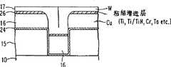
图2B-2E说明本发明的第一种改型,其中平面刻成的结构,可以是图2A所见的一个,或是图3B所见的一个,或是在涂覆的介质上形成了开口14的任何其它结构,然后,有一淀积的难熔金属层15盖在该无机介质层13以及在间隙14底部露出的衬底10上。为达到此目的,最好采用薄膜工艺技术手册(Handbook of Thin FilmTechnology,eds.Maissel和Glen,McGraw-Hill Co,1983,pp1-100)所述的蒸发PVD技术。此刻采用蒸发PVD的一个重要优点在于难熔金属层15不会覆盖住介质开口14的侧壁。应该理解,PVD准直溅、类似于美国专利4,824,544叙述的方法都能用于本发明的实施,但是,与图2B所示的情况相反,准直溅射产生共形层会涂敷开口14的侧壁。使用准直溅射产生难熔衬垫将于下面详细讨论。难熔金属可以是钛(Ti)、钛合金或复合物,诸如Ti/TiN、钨(W)、钛/钨(Ti/W)合金、或铬(Cr),或钽(Ta)及其合金,或某些其它合适的材料。要是待形成的为铜基的导线或通路,那末就应使用对铜能起扩散阻挡作用的难熔金属,使得在开口14中淀积铜的后续工艺时,能防止铜扩散到衬底10中。Figures 2B-2E illustrate a first modification of the present invention in which the planar engraved structure may be the one seen in Figure 2A, or the one seen in Figure 3B, or openings are formed in the
接着,用蒸发PVD法在难熔金属15上面淀积单一的、二元或三元的金属化层16,再说,由于采用蒸发法,开口14的侧壁不会涂敷上该金属。但是,应该理解,金属化16层也能用准直溅射施加上,这种情况下,开口14内和介质叠层的顶上,为共形的金属化涂层。最好,该金属化为AlxCuy,这里x与y的和等于1,而x与y两者都大于或等于0,且小于或等于1;可是,三元合金,如Al-Pd-Cu和多元合金,如Al-Pd-Nb-Au也都是适合的。金属化层16的本质特点在于,与难熔金属15比较,金属化层16为一种低阻率的软材料。更可取的是,表示导线图形或层间通路图形的开口14要用金属化层16填充到比导线或通路表面低100至400nm的深度。应该明白,图4A-E、5A-E和7A-B表示的金属化16层应是上述相类的东西。Next, a single, binary or
图2c表示出一种难熔金属17,诸如钨、钴、镍、钼,或合金/化合物,如Ti/TiN被淀积在该结构上。难熔金属17的淀积可以是一步CVD或两步工艺过程,而图4A-E作出最好的说明,其中第一步骤包括准直溅射或类似工艺淀积一层,增进粘合的化合物如钛或氮化钛,以形成共形的复盖涂膜,而第二步骤包括淀积一钨的薄CVD层,以达到高度的共形性。CVD淀积难熔金属最好用SH4或H2还原WF6来实现。尤其好的CVD工艺过程包括SiH4还原WF6后继之以H2还原WF6。因为,在TiN层的顶上,用SiH4还原WF6的CVD钨,生长平整,但用H2还原则不然。难熔金属17为底下开口14中的低电阻率软金属化层17提供耐磨损、抗侵蚀,以及抗电迁移的涂层。采用SiH4还原WF6做CVD特别优越,SiH4与WF6的比率可以改变,能把不同的硅量混入到钨中以达到有益的特性。举例来说,填充介质中的开口14时,以0.5SiH4比WF6的比率淀积难熔金属17应是更可取的,因为这么做会得到低阻难熔金属;但是,用于介质顶面的淀积,则按2.0SiH4对WF6的比率,因为这样得到的会混入更多的硅使难熔金属更耐磨损。利用上述的CVD技术,可用掺硅的钨作为抗磨损的涂层或抛光阻挡物(例如,化学-机械抛光中更能经受用硝酸铁的氧化铝粉悬浮液)。由于通过蒸发施加的金属化层16不会覆盖着开口14的侧壁,而CVD施加的难熔金属17却产生环绕金属化层16的锥状侧壁,且该金属化层16完全被密封在难熔金属17与底下难熔金属15之中。Figure 2c shows that a
图2D和2E表示CVD施加难熔金属17产生一种结构后被平整化了的结构,其中的两部分导电通路或导线包括中心的低阻软金属化层16及密封金属化层16的耐磨损硬难熔金属17,其顶面与衬底10上介质复合层的顶面一般齐。用悬浮液,诸如稀硝酸铁的氧化铝粉液化学-机械抛光,或在含SF6或者氯基的化学物中RIE,可以在一步或两步工序中完成平整化。如果采用化学-机械抛光法,则要选择能除去该叠层上不同金属层的悬浮液。举个例,用氧化铝粉的稀硝酸铁悬浮液能除去铜顶面上的Ti/TiN/W,然后。换用不含氧化铝粉的悬浮液就能除去留下的铜。Figures 2D and 2E show the planarized structure after CVD application of the
RIE除去难熔金属层17之后,结合用化学-机械抛光留下物金属化层16,预料也能留下无机或有机层13顶面上的难熔金属17,设想一种特定的平整化过程,包括或者用化学-机械抛光或者用SF6或Cl2基的化学物的RIE除去钨的难熔金属层17,直至如图2D所示的Al-Cu合金金属化层16的表面,然后,利用钨作掩模,刻蚀Al-Cu CVD层直到无机层13的表面,最后,介质表面留下的钨17或经抛光、湿法腐蚀或在Cl2中RIE腐蚀,就得到图2E所见的结构。After RIE removal of
图4A到4E表示出本发明的另一种改型,与上面相同的类似构件在各图中均标以相同的标号。如图4A所示,铜金属化层16淀积在衬底上形成的无机或有机介质15产生的开口14中。图4A所示结构与图2B所示结构的主要区别在于,淀积铜金属化之前,准直溅射淀积一薄难金属金属层24,诸如钛、氮化钛(TiN)、钨、钽,或合金及其化合物盖在无机或者有机介质15的表面及开口14通路的内侧。Figures 4A to 4E show another modification of the present invention, and similar components to the same as above are designated with the same reference numerals in each figure. As shown in FIG. 4A, a
如上所述,对准直溅射,Rossnagel等的美国专利4,824,544已作概述,其中还讨论过剥离操作过程。本发明已经发现,采用准直溅射,在高压下散射占优势,相反在低压下定向性淀积占优势,可容许在大高宽比的亚微米级槽或通路内形成共形涂层(例如,侧壁和底面都被涂敷上)。高宽比,一般是指槽或通路的高度对沟槽的宽度或通路的直径之比。对高宽比大于2的槽或通路,通常认为具有大的高宽比。就准直溅射来说,高于1毫乇(mTorr)气压,散射往往占优势(最好在3毫乇(3mTorr)附近),而低于1毫乇(1mTorr),则定向淀积占优势。结合图5A-E和图6,下面将更详细地陈述准直溅射。As noted above, collimated sputtering is outlined in US Patent 4,824,544 to Rossnagel et al., which also discusses lift-off operations. The present inventors have discovered that the use of collimated sputtering, where scattering prevails at high pressure and conversely directional deposition prevails at low pressure, allows the formation of conformal coatings in sub-micron trenches or vias of high aspect ratio ( For example, both the side walls and the bottom surface are coated). The aspect ratio generally refers to the ratio of the height of the groove or via to the width of the trench or the diameter of the via. A slot or via with an aspect ratio greater than 2 is generally considered to have a large aspect ratio. As far as collimated sputtering is concerned, above 1 mTorr (mTorr) pressure, scattering is often dominant (preferably around 3 mTorr (3mTorr)), while below 1 mTorr (1mTorr), directional deposition dominates. Advantage. Collimated sputtering will be set forth in more detail below in conjunction with FIGS. 5A-E and FIG. 6 .
当用铜基合金金属化层16时,如图4A所示,用一难熔金属层24完全覆盖开口14的底面与侧壁就尤其重要,因为后续的高温处理会使铜扩散到衬底10中,如果不设置扩散阻挡层就会破坏器件。无论用蒸发PVD、准直溅射还是其它技术都可以淀积铜金属化层16。当要填充的是亚微米大高宽比的孔时,现有的CVD技术对用铝与铜基合金来填充这样的孔已经失败;因此,最好的填充方法是通过PVD技术。When metallizing the
淀积金属化层16之后,再把钛、Ti/TiN,钽或铬的薄层26施加在该铜金属化层16的表面,以增进粘结力。然后,通过CVD,用SiH4或H2还原WF6淀积难熔金属,如钨,产生图4B所示的结构,正如上面已解释的,CVD时可利用改变SiH4与WF6的比,以利于制成较硬,更耐磨损,靠近介质15的顶面的含硅钨层。界面上的薄层26应这样选择,即不会浸蚀底下的铜金属化层16。After depositing the
图4c指明,首先经抛光或经RIE将钨平整化,而图4d表明,经湿法腐蚀,有选择地除去铜。如果要形成的是铜或铜合金线,以过氧化氢((H2O2)和四氧化氢(H2O4)为基的湿法腐蚀液来平整铜是有利的。室温下,这类溶液决不会腐蚀钨或介质,但会腐蚀掉位于介质上的所有的铜,因为没有保护铜不受湿法腐蚀液腐蚀(例如,在室温下,H2O2几乎有无限的选择性。图4e表明,湿法腐蚀后,该钨17可以用RIE、抛光或其它技术有选择地除去。除去难熔金属17钨的可取方法,是用氧化铝粉的硝酸铁悬浮液之类化学-机械抛光介质15表面之上的凸出物,因为钨是一种很硬的材料,经受化学-机械抛光时,不会受擦伤或侵蚀。上面详述的决不是三步工序的方法,更可取的是用化学-机械抛光一步工序,以除去钨的难熔金属17、薄层26的粘结增进层,以及位于绝缘物15表面上的铜金属化层16。Figure 4c indicates that the tungsten is first planarized by polishing or by RIE, while Figure 4d shows that copper is selectively removed by wet etching. If copper or copper alloy wires are to be formed, it is advantageous to use a wet etching solution based on hydrogen peroxide ((H2 O2 ) and hydrogen tetraoxide (H2 O4 ) to level the copper. At room temperature, this Such solutions will never corrode tungsten or the dielectric, but will corrode any copper on the dielectric since there is no protection for the copper from the wet etchant (e.g.,H2O2 has almost infinite selectivity at roomtemperature .Figure 4e shows that after wet etching, the
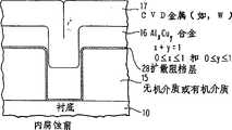
图5A至图5E表示本发明还有一种改型,其中同样的标号指同样的结构。图5A表明,在用准直溅射,如Rossnagel等人在J.Vac.Sci.Technol.2,261(mar/Apr.1991)和美国专利4,824,544合并参照的准直溅射法,以全部或局部的共形方式金属化之前,在开口14内淀积一层难熔金属衬垫28。准直溅射时,在气压大于0.5毫乇(mTorr)下,难熔金属原子穿过深度对面积的高宽比大于1的蜂窝状结构。表1给出已用于衬垫淀积的条件。5A to 5E show a modification of the present invention, wherein the same reference numerals refer to the same structure. Fig. 5A shows that, in collimated sputtering, such as Rossnagel et al in J.Vac.Sci.Technol.2, 261 (mar/Apr.1991) and U.S. Patent 4,824,544 combined reference collimated sputtering method, with all or A refractory metal liner 28 is deposited within opening 14 prior to localized conformal metallization. During collimated sputtering, at a gas pressure greater than 0.5 millitorr (mTorr), the refractory metal atoms pass through a honeycomb structure with an aspect ratio of depth to area greater than 1. Table 1 gives the conditions that have been used for liner deposition.
表1 Table 1
准直淀积衬垫Collimating deposition liner
高宽比 复盖高差厚度 底部/顶面(%)Aspect Ratio Covering Height Difference Thickness Bottom/Top Surface (%)
侧壁/顶面(%)side wall/top surface (%)
1∶1 38 601:1 38 60
1∶2 39 701:2 39 70
1∶4 42 1001:4 42 100
非准直Non-collimated
0 10 12在表1所给出的研究中,压力从0.5毫乇mT变到15毫乇mT,而功率从0.5千瓦变到12千瓦。表1清楚地指出,不用准直溅射时的恶劣复盖高差厚度比。采用较高的气压(如,3毫乇)而准直器的高宽比至小1∶1用Ti/TiN或Ti/W双层来涂敷高宽比大于7至8的通路或接触孔,所得到的复盖高差厚度比,对底面大于40%,对侧壁大于30%,对本技术领域来说,这是很大进步,因此容许半导体制造者在大高宽比的通路或槽中制备共形层,将增强CVD钨的粘结力。并且,正如下面将详加陈述的,制成的TiN或其它合适材料的共形层将给铜基合金提供一种有效的扩散阻挡层。如上所述,为了充份地覆盖槽或通路的侧壁及底部,应采用散射淀积占优势的气压(如,高于1毫乇),而不应采用定向淀积居优势的低气压。0 10 12 In the study given in Table 1, the pressure was varied from 0.5 mTorr to 15 mTorr and the power was varied from 0.5 kW to 12 kW. Table 1 clearly indicates the poor coverage height-to-thickness ratio without collimated sputtering. Use higher gas pressures (e.g., 3 mTorr) and collimator aspect ratios as small as 1:1 Use Ti/TiN or Ti/W bilayers to coat vias or contact holes with aspect ratios greater than 7 to 8 , The obtained coverage height difference thickness ratio is greater than 40% for the bottom surface and greater than 30% for the sidewall. This is a great progress in the field of technology, so it allows semiconductor manufacturers to use large aspect ratio vias or grooves Preparation of a conformal layer in CVD will enhance the adhesion of CVD tungsten. Also, as will be detailed below, the formed conformal layer of TiN or other suitable material will provide an effective diffusion barrier for copper based alloys. As noted above, to adequately cover the sidewalls and bottoms of trenches or vias, gas pressures (eg, greater than 1 mTorr) that predominate for diffuse deposition should be used rather than low gas pressures that predominate for directional deposition.
如上所述,图6呈现的是一幅PVD准直溅射在通路中产生的一个难熔金属衬垫的SEM显微照片。图6表明,能够实现通路底部及侧壁的完全覆盖,用N2等离子,与氩一起在钛靶下,就地淀积TiN。该衬垫能改善粘结力及防止CVD钨对底下衬底的任何浸蚀。当准直器的高宽比增大时,衬垫的共形度也增加了。As mentioned above, Figure 6 presents a SEM micrograph of a refractory metal liner produced in a via by collimated PVD sputtering. Figure 6 shows that complete coverage of via bottoms and sidewalls can be achieved usingN2 plasma, together with argon, to deposit TiN in situ under a titanium target. The liner improves adhesion and prevents any attack of the underlying substrate by the CVD tungsten. As the aspect ratio of the collimator increases, the conformality of the spacer also increases.
如把铜导线或通路用之于该结构,就需要坚固的衬垫用作扩散阻挡层。低压准直溅射的难熔金属衬垫(如,Ta、Ti/TiN,或Ti/W等)会在介质中开口14的侧壁上造成一种多孔的结构。为防止这种多孔结构,而在侧壁上制出致密的结构,要采取两步准直工序。详细说,第一步骤,用低于0.8毫乇的气压淀积一薄的衬垫层,达到底高大于60%的覆盖范围,而第二步骤,原处不动,将气压增至3到4毫乇,使用相同的准直器,在侧壁上得到一种致密的微结构。本发明之前,没有一种方法能够在很大的高宽比的亚微米孔中,尤其在低温下,形成一种衬垫。这些结果,类似于用Ti/W和Ti/TiN双层衬垫做CVD难熔金属17或低阻软金属的扩散阻挡层。If copper wires or vias are used for this structure, a solid liner is required to act as a diffusion barrier. A low-pressure collimated sputtered refractory metal liner (eg, Ta, Ti/TiN, or Ti/W, etc.) will create a porous structure on the sidewall of the
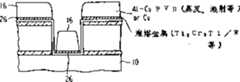
图5B-E表示出本发明另一种改型中,实施类似于图2B-E和图4A-E表示的那些工序。与图4A相似,图5B示明有一种粘结增进剂层26,诸如Ti、Cr、Ta、Ti/N之类,用PVD蒸发淀积,盖在难熔金属衬底顶上与间隙14的底部。与图2B相似,图5B示明,通过PVD蒸发技术将Al-Cu合金或别的金属化层16淀积到介质层表面以下100至400nm的水平位置。图5C-E分别表示出淀积共形层钨或其他难熔材料,以覆盖低阻金属化层16,通过RIE或抛光平整化钨,等等之类,而平整化该结构可用H2O2湿法腐蚀铝-铜合金之后,接着化学-机械抛光钨的两步工序如图4c和4d所示,或者通过RIE或化学-机械抛光的一步工序简单地加以平整化。关于一步工序化学-机械抛光,悬浮液可采用与用于抛光钨相同的悬浮液。类似图2E所示结构,图5E所示的结构有密封着低阻金属化层16的CVD难熔金属17,还有一锥形的难熔金属17区。Figures 5B-E show another modification of the invention in which processes similar to those shown in Figures 2B-E and Figures 4A-E are performed. Similar to FIG. 4A, FIG. 5B shows an
图7A和7B表示本发明的再一种改型,其中相同的标号相同的构件。正如图7A所示,不论共形的,以难熔金属为好的衬垫/扩散阻挡层28,还是共形的AlxCuy或其它合适的材料的低阻合金或金属化层16都用PVD准直溅射淀积在衬底10的无机或有机介质的开口中,接着,CVD淀积难熔金属17覆盖层,诸如钨、钛、钽、之类包覆该结构。图7B示出经RIE,化学-机械抛光或其它技术使之平整化了的结构。将图7B的结构与图5E的结构予以对比,可以看出,通路或导线的形状是很不同的。虽然,两种结构都包含一个由难熔金属17包覆的低阻金属层16,但这两种金属化很可能适用于不同的环境。Figures 7A and 7B show yet another modification of the present invention, in which the same components are numbered the same. As shown in FIG. 7A, either a conformal, refractory metal-based liner/diffusion barrier 28, or a conformalAlxCuyor other suitable low-resistance alloy or
已经用按上面陈述的技术制造的难熔金属包覆的导线进行实验检测,实验中,该导线长度从13.45cm变到50cm,芯片面积接近1.6mm2。金属间距从1μm变到2μm。要填充的孔的高宽比为2至8,而导线为2到4。Experimental examinations have been carried out with refractory metal clad wires fabricated according to the technique stated above. In the experiments, the wire lengths were varied from 13.45 cm to 50 cm, and the chip area was close to 1.6 mm2 . The metal pitch varies from 1 μm to 2 μm. The hole to be filled has an aspect ratio of 2 to 8, and the wire is 2 to 4.
表2 Table 2
抛去后,钨覆盖的低电阻率金属导线的电阻a(A)采用蒸发形成的b
a)全部实验中,导线的长度从13.5cm变到50cm,芯片面积接近1.6mm2。金属间距从1μm变到2μm。填充孔的高宽比为2至8,以及对导线为2至4。a) In all the experiments, the length of the wire was changed from 13.5cm to 50cm, and the chip area was close to 1.6mm2 . The metal pitch varies from 1 μm to 2 μm. The aspect ratio is 2 to 8 for the filled holes and 2 to 4 for the wires.
b)蒸发实验中,用准直溅射淀积Ti/TiN双层。b) In evaporation experiments, Ti/TiN bilayers were deposited by collimated sputtering.
c)准直高宽比为1∶1。c) The collimation aspect ratio is 1:1.
d)溅射的气压范围在0.5至0.8毫乇间。d) The gas pressure range for sputtering is between 0.5 and 0.8 mTorr.
表2的结果表明,新技术加工的成品率很高,并且导线电阻不因有钨的包覆而变化较大。某些上面的数据表明,Al-Cu合金下面有钛时,电阻增大了,这是由于界面处形成TiAl3的缘故。还发现,在钛与铝-铜层之间设置一层钛合金或化合物(例如,TiN)可以防止形成TiAl3,因而仍能保持电阻较小。表2末尾的项目表明,如果采用非准直溅射法,即该种溅射应在低气压(例如,低于1毫乇)下进行,也就是定向溅射占了优势。The results in Table 2 show that the yield of the new technology is very high, and the wire resistance does not change greatly due to the coating of tungsten. Some of the above data show that the resistance increases when Al-Cu alloys are underlaid with titanium due to the formation ofTiAl3 at the interface. It has also been found that placing a layer of titanium alloy or compound (eg TiN) between the titanium and the aluminum-copper layer prevents the formation ofTiAl3 and thus still keeps the resistance low. The entries at the end of Table 2 indicate that if non-collimated sputtering is used, ie, the sputtering should be performed at low pressure (eg, less than 1 mTorr), ie, directional sputtering predominates.
可以预料,在化学-机械抛光之后,对难熔金属覆盖层施行RIE,用H2O2,或H2O4作湿法腐蚀,把该覆盖层的厚度降至最起码的层厚限度。一层厚的难熔金属会增加不希望有的电容。之所以考虑用后抛光湿法腐蚀或RIE过程,使半导体设计者有可能用厚的难熔金属及为其底下的低阻Al-Cu导线或通孔在化学一机械抛光时提供最大的保护,还能随后除去任何过剩的难熔金属,实现难熔金属覆盖很薄的一种结构,举例说,可敷设一层500-600nm厚的难熔金属,用双抵挡抛光损伤,而后,通过湿法腐蚀或RIE,可以再把难熔金属层降至50nm的层厚。It is contemplated that after chemical-mechanical polishing, RIE is performed on the refractory metal coating, wet etching with H2 O2 , or H2 O4 to reduce the thickness of the coating to the minimum layer thickness limit. A thick layer of refractory metal can add unwanted capacitance. The reason for considering post-polish wet etching or RIE process is to make it possible for semiconductor designers to use thick refractory metal and its underlying low-resistance Al-Cu wires or vias to provide maximum protection during chemical-mechanical polishing. It is also possible to subsequently remove any excess refractory metal to achieve a structure in which the refractory metal is covered very thinly, for example, by laying down a layer of refractory metal 500-600nm thick, using double resist polishing damage, and then, by wet Etching or RIE can further reduce the refractory metal layer to a layer thickness of 50nm.
图8显示出一多层半导体器件的实例,该器件包括一几乎与绝缘层顶面齐平的有钨覆盖的AlxCuy合金导线的顶面。如上面详细陈述的那样,CVD钨的通路或槽,最好包含一准直溅射以增进粘结力的TiN衬垫。在本发明的实际范围内,还可制造出许多其它半导体器件。FIG. 8 shows an example of a multilayer semiconductor device including a top surface ofAlxCuy alloy wire covered with tungsten nearly flush with the top surface of the insulating layer. As detailed above, the CVD tungsten vias or trenches preferably include a TiN liner that is collimated sputtered to improve adhesion. Many other semiconductor devices can also be fabricated within the practical scope of the present invention.
图9A和9B是一种半导体器件的剖面SEM显微照片。图9A显示了由SiO2之间和顶部以Al-Cu合金隔开,从硅表面向上伸出的SiO2部分。而Al-Cu合金之间及顶上为CVD钨层。图9A是表示抛光前,有盖层导线的一种结构。图9B则显示化学-机械抛光除去SiO2伸出部分顶面上的钨与Al-Cu合金后的多层结构剖面的SEM显微照片。9A and 9B are cross-sectional SEM micrographs of a semiconductor device. Figure 9A shows portions of SiO2 protruding upward from the silicon surface separated by Al-Cu alloy between and on top of the SiO2 . Between and on top of the Al-Cu alloy is a CVD tungsten layer. Figure 9A shows a structure of capped wires before polishing. FIG. 9B shows a SEM micrograph of the cross-section of the multilayer structure after chemical-mechanical polishing to remove the tungsten and Al-Cu alloy on the top surface of the SiO2 overhang.
虽然本发明是用最佳实施例来描述,但本领域的技术人员均应认识到,后附的权利要求书的精神与范围内的修改都可实施本发明。While the invention has been described in terms of preferred embodiments, those skilled in the art will recognize that the invention can be practiced with modification within the spirit and scope of the appended claims.
Claims (11)
Translated fromChineseApplications Claiming Priority (3)
| Application Number | Priority Date | Filing Date | Title |
|---|---|---|---|
| US07/841,967US5300813A (en) | 1992-02-26 | 1992-02-26 | Refractory metal capped low resistivity metal conductor lines and vias |
| US841967 | 1992-02-26 | ||
| US841,967 | 1992-02-26 |
Related Parent Applications (1)
| Application Number | Title | Priority Date | Filing Date |
|---|---|---|---|
| CN93101333ADivisionCN1044649C (en) | 1992-02-26 | 1993-02-24 | Refractory metal covered low resistance metal conductor lines and vias and method of manufacture |
Publications (2)
| Publication Number | Publication Date |
|---|---|
| CN1192050Atrue CN1192050A (en) | 1998-09-02 |
| CN1111908C CN1111908C (en) | 2003-06-18 |
Family
ID=25286205
Family Applications (5)
| Application Number | Title | Priority Date | Filing Date |
|---|---|---|---|
| CN93101333AExpired - LifetimeCN1044649C (en) | 1992-02-26 | 1993-02-24 | Refractory metal covered low resistance metal conductor lines and vias and method of manufacture |
| CN94115341AExpired - LifetimeCN1081390C (en) | 1992-02-26 | 1994-09-15 | Refractory metal capped low resistivity metal conductor lines and vias formed using PVD and CVD |
| CNB971195579AExpired - LifetimeCN1150597C (en) | 1992-02-26 | 1997-09-25 | Method for forming liners in submicron holes and lines with large aspect ratios |
| CN97119558AExpired - LifetimeCN1111908C (en) | 1992-02-26 | 1997-09-25 | Semiconductor device |
| CN97119556AExpired - LifetimeCN1112730C (en) | 1992-02-26 | 1997-09-25 | Refractory metal capped low resistivity metal conductor lines and vias formed using PVD and CVD |
Family Applications Before (3)
| Application Number | Title | Priority Date | Filing Date |
|---|---|---|---|
| CN93101333AExpired - LifetimeCN1044649C (en) | 1992-02-26 | 1993-02-24 | Refractory metal covered low resistance metal conductor lines and vias and method of manufacture |
| CN94115341AExpired - LifetimeCN1081390C (en) | 1992-02-26 | 1994-09-15 | Refractory metal capped low resistivity metal conductor lines and vias formed using PVD and CVD |
| CNB971195579AExpired - LifetimeCN1150597C (en) | 1992-02-26 | 1997-09-25 | Method for forming liners in submicron holes and lines with large aspect ratios |
Family Applications After (1)
| Application Number | Title | Priority Date | Filing Date |
|---|---|---|---|
| CN97119556AExpired - LifetimeCN1112730C (en) | 1992-02-26 | 1997-09-25 | Refractory metal capped low resistivity metal conductor lines and vias formed using PVD and CVD |
Country Status (8)
| Country | Link |
|---|---|
| US (8) | US5300813A (en) |
| EP (3) | EP0966037B1 (en) |
| JP (1) | JP2516307B2 (en) |
| KR (4) | KR0128264B1 (en) |
| CN (5) | CN1044649C (en) |
| DE (3) | DE69332917T2 (en) |
| SG (8) | SG115407A1 (en) |
| TW (1) | TW291576B (en) |
Families Citing this family (351)
| Publication number | Priority date | Publication date | Assignee | Title |
|---|---|---|---|---|
| US5300813A (en)* | 1992-02-26 | 1994-04-05 | International Business Machines Corporation | Refractory metal capped low resistivity metal conductor lines and vias |
| DE69327600T2 (en)* | 1992-02-28 | 2000-06-21 | Stmicroelectronics, Inc. | Manufacturing process of submicron contacts |
| US5612254A (en)* | 1992-06-29 | 1997-03-18 | Intel Corporation | Methods of forming an interconnect on a semiconductor substrate |
| US5739579A (en)* | 1992-06-29 | 1998-04-14 | Intel Corporation | Method for forming interconnections for semiconductor fabrication and semiconductor device having such interconnections |
| US5561082A (en)* | 1992-07-31 | 1996-10-01 | Kabushiki Kaisha Toshiba | Method for forming an electrode and/or wiring layer by reducing copper oxide or silver oxide |
| US5596172A (en)* | 1993-05-07 | 1997-01-21 | Motorola, Inc. | Planar encapsulation process |
| US5412250A (en)* | 1993-09-24 | 1995-05-02 | Vlsi Technology, Inc. | Barrier enhancement at the salicide layer |
| JP3297220B2 (en)* | 1993-10-29 | 2002-07-02 | 株式会社東芝 | Semiconductor device manufacturing method and semiconductor device |
| JP2699839B2 (en)* | 1993-12-03 | 1998-01-19 | 日本電気株式会社 | Method for manufacturing semiconductor device |
| KR0179677B1 (en)* | 1993-12-28 | 1999-04-15 | 사토 후미오 | Semiconductor device wiring or electrode |
| US5430328A (en)* | 1994-05-31 | 1995-07-04 | United Microelectronics Corporation | Process for self-align contact |
| EP0697730B1 (en)* | 1994-08-05 | 1999-11-24 | International Business Machines Corporation | Method of forming an Al-Ge alloy with WGe polishing stop |
| US5472913A (en)* | 1994-08-05 | 1995-12-05 | Texas Instruments Incorporated | Method of fabricating porous dielectric material with a passivation layer for electronics applications |
| US5686356A (en) | 1994-09-30 | 1997-11-11 | Texas Instruments Incorporated | Conductor reticulation for improved device planarity |
| KR0171069B1 (en)* | 1994-10-27 | 1999-03-30 | 문정환 | Method of forming metal contact of semiconductor device |
| US5602423A (en)* | 1994-11-01 | 1997-02-11 | Texas Instruments Incorporated | Damascene conductors with embedded pillars |
| WO1996016436A1 (en)* | 1994-11-18 | 1996-05-30 | Advanced Micro Devices, Inc. | Method of making a chemical-mechanical polishing slurry and the polishing slurry |
| US5580823A (en)* | 1994-12-15 | 1996-12-03 | Motorola, Inc. | Process for fabricating a collimated metal layer and contact structure in a semiconductor device |
| US5550405A (en)* | 1994-12-21 | 1996-08-27 | Advanced Micro Devices, Incorporated | Processing techniques for achieving production-worthy, low dielectric, low interconnect resistance and high performance ICS |
| EP0720228B1 (en)* | 1994-12-29 | 2002-07-10 | STMicroelectronics, Inc. | Method of making a semiconductor connection structure |
| EP0720078B1 (en)* | 1994-12-30 | 1999-04-28 | Co.Ri.M.Me. | Threshold voltage extracting method and circuit using the same |
| US6285082B1 (en) | 1995-01-03 | 2001-09-04 | International Business Machines Corporation | Soft metal conductor |
| US5920296A (en)* | 1995-02-01 | 1999-07-06 | Pixel International | Flat screen having individually dipole-protected microdots |
| US5545592A (en)* | 1995-02-24 | 1996-08-13 | Advanced Micro Devices, Inc. | Nitrogen treatment for metal-silicide contact |
| TW290731B (en)* | 1995-03-30 | 1996-11-11 | Siemens Ag | |
| US6348708B1 (en)* | 1995-04-10 | 2002-02-19 | Lg Semicon Co., Ltd. | Semiconductor device utilizing a rugged tungsten film |
| TW298674B (en)* | 1995-07-07 | 1997-02-21 | At & T Corp | |
| US5747879A (en)* | 1995-09-29 | 1998-05-05 | Intel Corporation | Interface between titanium and aluminum-alloy in metal stack for integrated circuit |
| CN1198252A (en)* | 1995-09-29 | 1998-11-04 | 英特尔公司 | Metal stack for integrated circuit having two thin layers of titanium with dedicated chamber depositions |
| US5573633A (en)* | 1995-11-14 | 1996-11-12 | International Business Machines Corporation | Method of chemically mechanically polishing an electronic component |
| US6077781A (en)* | 1995-11-21 | 2000-06-20 | Applied Materials, Inc. | Single step process for blanket-selective CVD aluminum deposition |
| US6726776B1 (en) | 1995-11-21 | 2004-04-27 | Applied Materials, Inc. | Low temperature integrated metallization process and apparatus |
| KR0175410B1 (en)* | 1995-11-21 | 1999-02-01 | 김광호 | Thin film transistor substrate for liquid crystal display device and manufacturing method thereof |
| JPH09148431A (en)* | 1995-11-21 | 1997-06-06 | Nec Corp | Manufacture of semiconductor device |
| US6066358A (en)* | 1995-11-21 | 2000-05-23 | Applied Materials, Inc. | Blanket-selective chemical vapor deposition using an ultra-thin nucleation layer |
| US5877087A (en) | 1995-11-21 | 1999-03-02 | Applied Materials, Inc. | Low temperature integrated metallization process and apparatus |
| US5776836A (en)* | 1996-02-29 | 1998-07-07 | Micron Technology, Inc. | Self aligned method to define features smaller than the resolution limit of a photolithography system |
| US5950099A (en)* | 1996-04-09 | 1999-09-07 | Kabushiki Kaisha Toshiba | Method of forming an interconnect |
| US5654234A (en)* | 1996-04-29 | 1997-08-05 | Taiwan Semiconductor Manufacturing Company, Ltd. | Method for forming a void-free tungsten-plug contact in the presence of a contact opening overhang |
| US5756396A (en)* | 1996-05-06 | 1998-05-26 | Taiwan Semiconductor Manufacturing Company Ltd | Method of making a multi-layer wiring structure having conductive sidewall etch stoppers and a stacked plug interconnect |
| US5993686A (en)* | 1996-06-06 | 1999-11-30 | Cabot Corporation | Fluoride additive containing chemical mechanical polishing slurry and method for use of same |
| US6429120B1 (en) | 2000-01-18 | 2002-08-06 | Micron Technology, Inc. | Methods and apparatus for making integrated-circuit wiring from copper, silver, gold, and other metals |
| JPH1064902A (en)* | 1996-07-12 | 1998-03-06 | Applied Materials Inc | Aluminum film forming method and film forming apparatus |
| US6077768A (en)* | 1996-07-19 | 2000-06-20 | Motorola, Inc. | Process for fabricating a multilevel interconnect |
| US5783485A (en)* | 1996-07-19 | 1998-07-21 | Motorola, Inc. | Process for fabricating a metallized interconnect |
| US6001420A (en) | 1996-09-23 | 1999-12-14 | Applied Materials, Inc. | Semi-selective chemical vapor deposition |
| US5965459A (en)* | 1996-10-11 | 1999-10-12 | International Business Machines Corporation | Method for removing crevices induced by chemical-mechanical polishing |
| US6020263A (en)* | 1996-10-31 | 2000-02-01 | Taiwan Semiconductor Manufacturing Company, Ltd. | Method of recovering alignment marks after chemical mechanical polishing of tungsten |
| US5849367A (en)* | 1996-12-11 | 1998-12-15 | Texas Instruments Incorporated | Elemental titanium-free liner and fabrication process for inter-metal connections |
| KR100339670B1 (en)* | 1996-12-12 | 2002-06-05 | 야마모토 카즈모토 | Method of manufacturing semiconductor device |
| US6537905B1 (en) | 1996-12-30 | 2003-03-25 | Applied Materials, Inc. | Fully planarized dual damascene metallization using copper line interconnect and selective CVD aluminum plug |
| US6110828A (en)* | 1996-12-30 | 2000-08-29 | Applied Materials, Inc. | In-situ capped aluminum plug (CAP) process using selective CVD AL for integrated plug/interconnect metallization |
| JPH10209279A (en)* | 1997-01-27 | 1998-08-07 | Matsushita Electron Corp | Forming method of metal plug |
| US6139697A (en)* | 1997-01-31 | 2000-10-31 | Applied Materials, Inc. | Low temperature integrated via and trench fill process and apparatus |
| US6268661B1 (en)* | 1999-08-31 | 2001-07-31 | Nec Corporation | Semiconductor device and method of its fabrication |
| US5916855A (en)* | 1997-03-26 | 1999-06-29 | Advanced Micro Devices, Inc. | Chemical-mechanical polishing slurry formulation and method for tungsten and titanium thin films |
| JP3111924B2 (en)* | 1997-04-11 | 2000-11-27 | 日本電気株式会社 | Method for manufacturing semiconductor device |
| US6139905A (en)* | 1997-04-11 | 2000-10-31 | Applied Materials, Inc. | Integrated CVD/PVD Al planarization using ultra-thin nucleation layers |
| US6080665A (en)* | 1997-04-11 | 2000-06-27 | Applied Materials, Inc. | Integrated nitrogen-treated titanium layer to prevent interaction of titanium and aluminum |
| US5981374A (en)* | 1997-04-29 | 1999-11-09 | International Business Machines Corporation | Sub-half-micron multi-level interconnection structure and process thereof |
| US6849557B1 (en)* | 1997-04-30 | 2005-02-01 | Micron Technology, Inc. | Undoped silicon dioxide as etch stop for selective etch of doped silicon dioxide |
| US6149974A (en)* | 1997-05-05 | 2000-11-21 | Applied Materials, Inc. | Method for elimination of TEOS/ozone silicon oxide surface sensitivity |
| US6605197B1 (en) | 1997-05-13 | 2003-08-12 | Applied Materials, Inc. | Method of sputtering copper to fill trenches and vias |
| US6130161A (en) | 1997-05-30 | 2000-10-10 | International Business Machines Corporation | Method of forming copper interconnections with enhanced electromigration resistance and reduced defect sensitivity |
| US6069068A (en) | 1997-05-30 | 2000-05-30 | International Business Machines Corporation | Sub-quarter-micron copper interconnections with improved electromigration resistance and reduced defect sensitivity |
| US5904565A (en)* | 1997-07-17 | 1999-05-18 | Sharp Microelectronics Technology, Inc. | Low resistance contact between integrated circuit metal levels and method for same |
| US6240199B1 (en) | 1997-07-24 | 2001-05-29 | Agere Systems Guardian Corp. | Electronic apparatus having improved scratch and mechanical resistance |
| US5989623A (en) | 1997-08-19 | 1999-11-23 | Applied Materials, Inc. | Dual damascene metallization |
| US6080655A (en) | 1997-08-21 | 2000-06-27 | Micron Technology, Inc. | Method for fabricating conductive components in microelectronic devices and substrate structures thereof |
| US6096576A (en)* | 1997-09-02 | 2000-08-01 | Silicon Light Machines | Method of producing an electrical interface to an integrated circuit device having high density I/O count |
| US5994775A (en)* | 1997-09-17 | 1999-11-30 | Lsi Logic Corporation | Metal-filled via/contact opening with thin barrier layers in integrated circuit structure for fast response, and process for making same |
| JP3545177B2 (en)* | 1997-09-18 | 2004-07-21 | 株式会社荏原製作所 | Method for forming multilayer embedded Cu wiring |
| US5990011A (en)* | 1997-09-18 | 1999-11-23 | Micron Technology, Inc. | Titanium aluminum alloy wetting layer for improved aluminum filling of damescene trenches |
| SG70654A1 (en) | 1997-09-30 | 2000-02-22 | Ibm | Copper stud structure with refractory metal liner |
| US6133139A (en) | 1997-10-08 | 2000-10-17 | International Business Machines Corporation | Self-aligned composite insulator with sub-half-micron multilevel high density electrical interconnections and process thereof |
| US6060388A (en)* | 1997-10-29 | 2000-05-09 | International Business Machines Corporation | Conductors for microelectronic circuits and method of manufacture |
| WO1999027579A1 (en) | 1997-11-26 | 1999-06-03 | Applied Materials, Inc. | Damage-free sculptured coating deposition |
| US7253109B2 (en) | 1997-11-26 | 2007-08-07 | Applied Materials, Inc. | Method of depositing a tantalum nitride/tantalum diffusion barrier layer system |
| TW374946B (en)* | 1997-12-03 | 1999-11-21 | United Microelectronics Corp | Definition of structure of dielectric layer patterns and the manufacturing method |
| US6129613A (en)* | 1998-01-30 | 2000-10-10 | Philips Electronics North America Corp. | Semiconductor manufacturing apparatus and method for measuring in-situ pressure across a wafer |
| US6424040B1 (en)* | 1998-02-04 | 2002-07-23 | Texas Instruments Incorporated | Integration of fluorinated dielectrics in multi-level metallizations |
| KR100275728B1 (en) | 1998-02-24 | 2001-01-15 | 윤종용 | Method for manufacturing barrier metal layer of semiconductor device and manufacturing method of metal interconnect using the same |
| US6287436B1 (en) | 1998-02-27 | 2001-09-11 | Innovent, Inc. | Brazed honeycomb collimator |
| US6211073B1 (en) | 1998-02-27 | 2001-04-03 | Micron Technology, Inc. | Methods for making copper and other metal interconnections in integrated circuits |
| US6281121B1 (en)* | 1998-03-06 | 2001-08-28 | Advanced Micro Devices, Inc. | Damascene metal interconnects using highly directional deposition of barrier and/or seed layers including (III) filling metal |
| JP3116897B2 (en)* | 1998-03-18 | 2000-12-11 | 日本電気株式会社 | Fine wiring formation method |
| US6303881B1 (en) | 1998-03-20 | 2001-10-16 | Viasystems, Inc. | Via connector and method of making same |
| US6455937B1 (en)* | 1998-03-20 | 2002-09-24 | James A. Cunningham | Arrangement and method for improved downward scaling of higher conductivity metal-based interconnects |
| US6598291B2 (en) | 1998-03-20 | 2003-07-29 | Viasystems, Inc. | Via connector and method of making same |
| US6140236A (en)* | 1998-04-21 | 2000-10-31 | Kabushiki Kaisha Toshiba | High throughput A1-Cu thin film sputtering process on small contact via for manufacturable beol wiring |
| US6218306B1 (en)* | 1998-04-22 | 2001-04-17 | Applied Materials, Inc. | Method of chemical mechanical polishing a metal layer |
| US6111301A (en)* | 1998-04-24 | 2000-08-29 | International Business Machines Corporation | Interconnection with integrated corrosion stop |
| US6022800A (en)* | 1998-04-29 | 2000-02-08 | Worldwide Semiconductor Manufacturing Corporation | Method of forming barrier layer for tungsten plugs in interlayer dielectrics |
| US6015749A (en)* | 1998-05-04 | 2000-01-18 | Taiwan Semiconductor Manufacturing Company | Method to improve adhesion between copper and titanium nitride, for copper interconnect structures, via the use of an ion implantation procedure |
| US6218288B1 (en) | 1998-05-11 | 2001-04-17 | Micron Technology, Inc. | Multiple step methods for forming conformal layers |
| US6127276A (en)* | 1998-06-02 | 2000-10-03 | United Microelectronics Corp | Method of formation for a via opening |
| US6153521A (en) | 1998-06-04 | 2000-11-28 | Advanced Micro Devices, Inc. | Metallized interconnection structure and method of making the same |
| US6056869A (en)* | 1998-06-04 | 2000-05-02 | International Business Machines Corporation | Wafer edge deplater for chemical mechanical polishing of substrates |
| JPH11354637A (en)* | 1998-06-11 | 1999-12-24 | Oki Electric Ind Co Ltd | Connection structure for wiring and formation of connection part of the wiring |
| US6211087B1 (en)* | 1998-06-29 | 2001-04-03 | Vlsi Technology, Inc. | Chemical wet etch removal of underlayer material after performing chemical mechanical polishing on a primary layer |
| US6391771B1 (en)* | 1998-07-23 | 2002-05-21 | Applied Materials, Inc. | Integrated circuit interconnect lines having sidewall layers |
| US6872984B1 (en) | 1998-07-29 | 2005-03-29 | Silicon Light Machines Corporation | Method of sealing a hermetic lid to a semiconductor die at an angle |
| US6303986B1 (en) | 1998-07-29 | 2001-10-16 | Silicon Light Machines | Method of and apparatus for sealing an hermetic lid to a semiconductor die |
| US6287977B1 (en) | 1998-07-31 | 2001-09-11 | Applied Materials, Inc. | Method and apparatus for forming improved metal interconnects |
| US6284656B1 (en) | 1998-08-04 | 2001-09-04 | Micron Technology, Inc. | Copper metallurgy in integrated circuits |
| US6060383A (en)* | 1998-08-10 | 2000-05-09 | Nogami; Takeshi | Method for making multilayered coaxial interconnect structure |
| TW436366B (en)* | 1998-08-21 | 2001-05-28 | United Microelectronics Corp | Method of fabricating a plug |
| US6048787A (en)* | 1998-09-08 | 2000-04-11 | Winbond Electronics Corp. | Borderless contacts for dual-damascene interconnect process |
| US6288442B1 (en) | 1998-09-10 | 2001-09-11 | Micron Technology, Inc. | Integrated circuit with oxidation-resistant polymeric layer |
| US6150269A (en)* | 1998-09-11 | 2000-11-21 | Chartered Semiconductor Manufacturing Company, Ltd. | Copper interconnect patterning |
| US6180506B1 (en) | 1998-09-14 | 2001-01-30 | International Business Machines Corporation | Upper redundant layer for damascene metallization |
| US6174803B1 (en) | 1998-09-16 | 2001-01-16 | Vsli Technology | Integrated circuit device interconnection techniques |
| US6057230A (en)* | 1998-09-17 | 2000-05-02 | Taiwan Semiconductor Manufacturing Company, Ltd. | Dry etching procedure and recipe for patterning of thin film copper layers |
| US6245668B1 (en)* | 1998-09-18 | 2001-06-12 | International Business Machines Corporation | Sputtered tungsten diffusion barrier for improved interconnect robustness |
| US6221775B1 (en)* | 1998-09-24 | 2001-04-24 | International Business Machines Corp. | Combined chemical mechanical polishing and reactive ion etching process |
| JP3169907B2 (en)* | 1998-09-25 | 2001-05-28 | 日本電気株式会社 | Multilayer wiring structure and method of manufacturing the same |
| US6069082A (en)* | 1998-10-13 | 2000-05-30 | Chartered Semiconductor Manufacturing Ltd. | Method to prevent dishing in damascene CMP process |
| US6149776A (en)* | 1998-11-12 | 2000-11-21 | Applied Materials, Inc. | Copper sputtering target |
| US6909114B1 (en) | 1998-11-17 | 2005-06-21 | Semiconductor Energy Laboratory Co., Ltd. | Semiconductor device having LDD regions |
| US6184137B1 (en) | 1998-11-25 | 2001-02-06 | Applied Materials, Inc. | Structure and method for improving low temperature copper reflow in semiconductor features |
| KR100493013B1 (en)* | 1998-11-30 | 2005-08-01 | 삼성전자주식회사 | Metal wiring layer formation method of semiconductor device_ |
| US6140240A (en)* | 1999-01-07 | 2000-10-31 | Vanguard International Semiconductor Corporation | Method for eliminating CMP induced microscratches |
| US6114246A (en)* | 1999-01-07 | 2000-09-05 | Vlsi Technology, Inc. | Method of using a polish stop film to control dishing during copper chemical mechanical polishing |
| US6323537B1 (en)* | 1999-01-13 | 2001-11-27 | Agere Systems Guardian Corp. | Capacitor for an integrated circuit |
| US6358790B1 (en) | 1999-01-13 | 2002-03-19 | Agere Systems Guardian Corp. | Method of making a capacitor |
| US20020127845A1 (en)* | 1999-03-01 | 2002-09-12 | Paul A. Farrar | Conductive structures in integrated circuits |
| US6157081A (en)* | 1999-03-10 | 2000-12-05 | Advanced Micro Devices, Inc. | High-reliability damascene interconnect formation for semiconductor fabrication |
| US6350690B1 (en)* | 1999-04-09 | 2002-02-26 | Advanced Micro Devices, Inc. | Process for achieving full global planarization during CMP of damascene semiconductor structures |
| US6235633B1 (en) | 1999-04-12 | 2001-05-22 | Taiwan Semiconductor Manufacturing Company | Method for making tungsten metal plugs in a polymer low-K intermetal dielectric layer using an improved two-step chemical/mechanical polishing process |
| US6329280B1 (en) | 1999-05-13 | 2001-12-11 | International Business Machines Corporation | Interim oxidation of silsesquioxane dielectric for dual damascene process |
| US6071808A (en)* | 1999-06-23 | 2000-06-06 | Lucent Technologies Inc. | Method of passivating copper interconnects in a semiconductor |
| US6046108A (en)* | 1999-06-25 | 2000-04-04 | Taiwan Semiconductor Manufacturing Company | Method for selective growth of Cu3 Ge or Cu5 Si for passivation of damascene copper structures and device manufactured thereby |
| US6130157A (en)* | 1999-07-16 | 2000-10-10 | Taiwan Semiconductor Manufacturing Company | Method to form an encapsulation layer over copper interconnects |
| US6521532B1 (en) | 1999-07-22 | 2003-02-18 | James A. Cunningham | Method for making integrated circuit including interconnects with enhanced electromigration resistance |
| US6551872B1 (en) | 1999-07-22 | 2003-04-22 | James A. Cunningham | Method for making integrated circuit including interconnects with enhanced electromigration resistance using doped seed layer and integrated circuits produced thereby |
| JP2001036080A (en) | 1999-07-26 | 2001-02-09 | Mitsubishi Electric Corp | Semiconductor device and manufacturing method thereof |
| US6413854B1 (en) | 1999-08-24 | 2002-07-02 | International Business Machines Corp. | Method to build multi level structure |
| JP2001135168A (en)* | 1999-08-26 | 2001-05-18 | Sharp Corp | Manufacturing method of metal wiring |
| US6433429B1 (en)* | 1999-09-01 | 2002-08-13 | International Business Machines Corporation | Copper conductive line with redundant liner and method of making |
| US7071557B2 (en)* | 1999-09-01 | 2006-07-04 | Micron Technology, Inc. | Metallization structures for semiconductor device interconnects, methods for making same, and semiconductor devices including same |
| US6441492B1 (en) | 1999-09-10 | 2002-08-27 | James A. Cunningham | Diffusion barriers for copper interconnect systems |
| US6734559B1 (en) | 1999-09-17 | 2004-05-11 | Advanced Micro Devices, Inc. | Self-aligned semiconductor interconnect barrier and manufacturing method therefor |
| US6207558B1 (en)* | 1999-10-21 | 2001-03-27 | Applied Materials, Inc. | Barrier applications for aluminum planarization |
| US6348736B1 (en) | 1999-10-29 | 2002-02-19 | International Business Machines Corporation | In situ formation of protective layer on silsesquioxane dielectric for dual damascene process |
| US6417106B1 (en) | 1999-11-01 | 2002-07-09 | Taiwan Semiconductor Manufacturing Company | Underlayer liner for copper damascene in low k dielectric |
| JP4236778B2 (en)* | 1999-11-01 | 2009-03-11 | 株式会社ルネサステクノロジ | Semiconductor device |
| US6551924B1 (en) | 1999-11-02 | 2003-04-22 | International Business Machines Corporation | Post metalization chem-mech polishing dielectric etch |
| US6114243A (en)* | 1999-11-15 | 2000-09-05 | Chartered Semiconductor Manufacturing Ltd | Method to avoid copper contamination on the sidewall of a via or a dual damascene structure |
| US6344419B1 (en) | 1999-12-03 | 2002-02-05 | Applied Materials, Inc. | Pulsed-mode RF bias for sidewall coverage improvement |
| US6403465B1 (en) | 1999-12-28 | 2002-06-11 | Taiwan Semiconductor Manufacturing Company | Method to improve copper barrier properties |
| US7211512B1 (en) | 2000-01-18 | 2007-05-01 | Micron Technology, Inc. | Selective electroless-plated copper metallization |
| US6376370B1 (en) | 2000-01-18 | 2002-04-23 | Micron Technology, Inc. | Process for providing seed layers for using aluminum, copper, gold and silver metallurgy process for providing seed layers for using aluminum, copper, gold and silver metallurgy |
| US6420262B1 (en) | 2000-01-18 | 2002-07-16 | Micron Technology, Inc. | Structures and methods to enhance copper metallization |
| US7262130B1 (en)* | 2000-01-18 | 2007-08-28 | Micron Technology, Inc. | Methods for making integrated-circuit wiring from copper, silver, gold, and other metals |
| US6956878B1 (en) | 2000-02-07 | 2005-10-18 | Silicon Light Machines Corporation | Method and apparatus for reducing laser speckle using polarization averaging |
| JP2001223460A (en)* | 2000-02-08 | 2001-08-17 | Fujitsu Ltd | Mounting circuit board and method of manufacturing the same |
| US6633083B2 (en)* | 2000-02-28 | 2003-10-14 | Advanced Micro Devices Inc. | Barrier layer integrity test |
| EP1143506A3 (en)* | 2000-04-04 | 2004-02-25 | Nippon Telegraph and Telephone Corporation | Pattern forming method |
| JP2001319928A (en)* | 2000-05-08 | 2001-11-16 | Hitachi Ltd | Semiconductor integrated circuit device and method of manufacturing the same |
| US6423629B1 (en)* | 2000-05-31 | 2002-07-23 | Kie Y. Ahn | Multilevel copper interconnects with low-k dielectrics and air gaps |
| US6674167B1 (en)* | 2000-05-31 | 2004-01-06 | Micron Technology, Inc. | Multilevel copper interconnect with double passivation |
| US6554979B2 (en) | 2000-06-05 | 2003-04-29 | Applied Materials, Inc. | Method and apparatus for bias deposition in a modulating electric field |
| US6501180B1 (en)* | 2000-07-19 | 2002-12-31 | National Semiconductor Corporation | Structure and method for controlling copper diffusion and for utilizing low K materials for copper interconnects in integrated circuit structures |
| US6218301B1 (en) | 2000-07-31 | 2001-04-17 | Applied Materials, Inc. | Deposition of tungsten films from W(CO)6 |
| JP2002050767A (en)* | 2000-08-04 | 2002-02-15 | Mitsubishi Electric Corp | Semiconductor device and manufacturing method thereof |
| JP2002050595A (en)* | 2000-08-04 | 2002-02-15 | Hitachi Ltd | Polishing method, wiring forming method, and semiconductor device manufacturing method |
| US6617689B1 (en)* | 2000-08-31 | 2003-09-09 | Micron Technology, Inc. | Metal line and method of suppressing void formation therein |
| US7518284B2 (en)* | 2000-11-02 | 2009-04-14 | Danfoss A/S | Dielectric composite and a method of manufacturing a dielectric composite |
| US7548015B2 (en)* | 2000-11-02 | 2009-06-16 | Danfoss A/S | Multilayer composite and a method of making such |
| US8181338B2 (en)* | 2000-11-02 | 2012-05-22 | Danfoss A/S | Method of making a multilayer composite |
| DE10054247C2 (en)* | 2000-11-02 | 2002-10-24 | Danfoss As | Actuator and method for its manufacture |
| US6436814B1 (en)* | 2000-11-21 | 2002-08-20 | International Business Machines Corporation | Interconnection structure and method for fabricating same |
| US6503641B2 (en)* | 2000-12-18 | 2003-01-07 | International Business Machines Corporation | Interconnects with Ti-containing liners |
| US6680514B1 (en)* | 2000-12-20 | 2004-01-20 | International Business Machines Corporation | Contact capping local interconnect |
| US6388327B1 (en) | 2001-01-09 | 2002-05-14 | International Business Machines Corporation | Capping layer for improved silicide formation in narrow semiconductor structures |
| JP2002208633A (en)* | 2001-01-10 | 2002-07-26 | Matsushita Electric Ind Co Ltd | Semiconductor device and method of manufacturing the same |
| JP2002217292A (en)* | 2001-01-23 | 2002-08-02 | Hitachi Ltd | Semiconductor integrated circuit device and method of manufacturing semiconductor integrated circuit device |
| US6524929B1 (en) | 2001-02-26 | 2003-02-25 | Advanced Micro Devices, Inc. | Method for shallow trench isolation using passivation material for trench bottom liner |
| US7177081B2 (en) | 2001-03-08 | 2007-02-13 | Silicon Light Machines Corporation | High contrast grating light valve type device |
| US7087997B2 (en) | 2001-03-12 | 2006-08-08 | International Business Machines Corporation | Copper to aluminum interlayer interconnect using stud and via liner |
| US6486038B1 (en) | 2001-03-12 | 2002-11-26 | Advanced Micro Devices | Method for and device having STI using partial etch trench bottom liner |
| US6521510B1 (en) | 2001-03-23 | 2003-02-18 | Advanced Micro Devices, Inc. | Method for shallow trench isolation with removal of strained island edges |
| US6534379B1 (en) | 2001-03-26 | 2003-03-18 | Advanced Micro Devices, Inc. | Linerless shallow trench isolation method |
| US6504225B1 (en)* | 2001-04-18 | 2003-01-07 | Advanced Micro Devices, Inc. | Teos seaming scribe line monitor |
| US6743666B1 (en)* | 2001-04-27 | 2004-06-01 | Advanced Micro Devices, Inc. | Selective thickening of the source-drain and gate areas of field effect transistors |
| JP4350337B2 (en)* | 2001-04-27 | 2009-10-21 | 富士通マイクロエレクトロニクス株式会社 | Semiconductor device |
| US7372160B2 (en)* | 2001-05-31 | 2008-05-13 | Stmicroelectronics, Inc. | Barrier film deposition over metal for reduction in metal dishing after CMP |
| US6865346B1 (en) | 2001-06-05 | 2005-03-08 | Silicon Light Machines Corporation | Fiber optic transceiver |
| JP2002367998A (en)* | 2001-06-11 | 2002-12-20 | Ebara Corp | Semiconductor device and manufacturing method therefor |
| US6521523B2 (en) | 2001-06-15 | 2003-02-18 | Silicon Integrated Systems Corp. | Method for forming selective protection layers on copper interconnects |
| US6782205B2 (en) | 2001-06-25 | 2004-08-24 | Silicon Light Machines | Method and apparatus for dynamic equalization in wavelength division multiplexing |
| US6747781B2 (en) | 2001-06-25 | 2004-06-08 | Silicon Light Machines, Inc. | Method, apparatus, and diffuser for reducing laser speckle |
| TW591089B (en)* | 2001-08-09 | 2004-06-11 | Cheil Ind Inc | Slurry composition for use in chemical mechanical polishing of metal wiring |
| US6953389B2 (en)* | 2001-08-09 | 2005-10-11 | Cheil Industries, Inc. | Metal CMP slurry compositions that favor mechanical removal of oxides with reduced susceptibility to micro-scratching |
| US6829092B2 (en) | 2001-08-15 | 2004-12-07 | Silicon Light Machines, Inc. | Blazed grating light valve |
| JP2003068848A (en)* | 2001-08-29 | 2003-03-07 | Fujitsu Ltd | Semiconductor device and manufacturing method thereof |
| US6989108B2 (en)* | 2001-08-30 | 2006-01-24 | Micron Technology, Inc. | Etchant gas composition |
| US6930364B2 (en)* | 2001-09-13 | 2005-08-16 | Silicon Light Machines Corporation | Microelectronic mechanical system and methods |
| US6746591B2 (en) | 2001-10-16 | 2004-06-08 | Applied Materials Inc. | ECP gap fill by modulating the voltate on the seed layer to increase copper concentration inside feature |
| US6956995B1 (en) | 2001-11-09 | 2005-10-18 | Silicon Light Machines Corporation | Optical communication arrangement |
| JP4198906B2 (en) | 2001-11-15 | 2008-12-17 | 株式会社ルネサステクノロジ | Semiconductor device and manufacturing method of semiconductor device |
| US6815342B1 (en)* | 2001-11-27 | 2004-11-09 | Lsi Logic Corporation | Low resistance metal interconnect lines and a process for fabricating them |
| DE60224844T2 (en)* | 2001-12-21 | 2009-01-08 | Danfoss A/S | DIELECTRIC ACTUATOR OR SENSOR STRUCTURE AND MANUFACTURING METHOD |
| KR100435784B1 (en)* | 2001-12-21 | 2004-06-12 | 동부전자 주식회사 | Fabricating method of metal wire in semiconductor device |
| US6800238B1 (en) | 2002-01-15 | 2004-10-05 | Silicon Light Machines, Inc. | Method for domain patterning in low coercive field ferroelectrics |
| US6770566B1 (en) | 2002-03-06 | 2004-08-03 | Cypress Semiconductor Corporation | Methods of forming semiconductor structures, and articles and devices formed thereby |
| US7294567B2 (en)* | 2002-03-11 | 2007-11-13 | Micron Technology, Inc. | Semiconductor contact device and method |
| US6797620B2 (en) | 2002-04-16 | 2004-09-28 | Applied Materials, Inc. | Method and apparatus for improved electroplating fill of an aperture |
| US6767751B2 (en) | 2002-05-28 | 2004-07-27 | Silicon Light Machines, Inc. | Integrated driver process flow |
| US7054515B1 (en) | 2002-05-30 | 2006-05-30 | Silicon Light Machines Corporation | Diffractive light modulator-based dynamic equalizer with integrated spectral monitor |
| US6822797B1 (en) | 2002-05-31 | 2004-11-23 | Silicon Light Machines, Inc. | Light modulator structure for producing high-contrast operation using zero-order light |
| US6829258B1 (en) | 2002-06-26 | 2004-12-07 | Silicon Light Machines, Inc. | Rapidly tunable external cavity laser |
| US6908201B2 (en) | 2002-06-28 | 2005-06-21 | Silicon Light Machines Corporation | Micro-support structures |
| US6813059B2 (en) | 2002-06-28 | 2004-11-02 | Silicon Light Machines, Inc. | Reduced formation of asperities in contact micro-structures |
| US6714337B1 (en) | 2002-06-28 | 2004-03-30 | Silicon Light Machines | Method and device for modulating a light beam and having an improved gamma response |
| US7057795B2 (en) | 2002-08-20 | 2006-06-06 | Silicon Light Machines Corporation | Micro-structures with individually addressable ribbon pairs |
| US6801354B1 (en) | 2002-08-20 | 2004-10-05 | Silicon Light Machines, Inc. | 2-D diffraction grating for substantially eliminating polarization dependent losses |
| EP1540807B1 (en)* | 2002-09-20 | 2013-01-09 | Danfoss A/S | Elastomer actuator and method of making the actuator |
| US6712480B1 (en) | 2002-09-27 | 2004-03-30 | Silicon Light Machines | Controlled curvature of stressed micro-structures |
| US6713873B1 (en)* | 2002-11-27 | 2004-03-30 | Intel Corporation | Adhesion between dielectric materials |
| US6928207B1 (en) | 2002-12-12 | 2005-08-09 | Silicon Light Machines Corporation | Apparatus for selectively blocking WDM channels |
| ATE440319T1 (en)* | 2002-12-12 | 2009-09-15 | Danfoss As | TOUCH SENSOR ELEMENT AND SENSOR GROUP |
| US6975032B2 (en) | 2002-12-16 | 2005-12-13 | International Business Machines Corporation | Copper recess process with application to selective capping and electroless plating |
| US6987600B1 (en) | 2002-12-17 | 2006-01-17 | Silicon Light Machines Corporation | Arbitrary phase profile for better equalization in dynamic gain equalizer |
| US7057819B1 (en) | 2002-12-17 | 2006-06-06 | Silicon Light Machines Corporation | High contrast tilting ribbon blazed grating |
| US6934070B1 (en) | 2002-12-18 | 2005-08-23 | Silicon Light Machines Corporation | Chirped optical MEM device |
| US6927891B1 (en) | 2002-12-23 | 2005-08-09 | Silicon Light Machines Corporation | Tilt-able grating plane for improved crosstalk in 1×N blaze switches |
| US7068372B1 (en) | 2003-01-28 | 2006-06-27 | Silicon Light Machines Corporation | MEMS interferometer-based reconfigurable optical add-and-drop multiplexor |
| US7286764B1 (en) | 2003-02-03 | 2007-10-23 | Silicon Light Machines Corporation | Reconfigurable modulator-based optical add-and-drop multiplexer |
| US6947613B1 (en) | 2003-02-11 | 2005-09-20 | Silicon Light Machines Corporation | Wavelength selective switch and equalizer |
| US6922272B1 (en) | 2003-02-14 | 2005-07-26 | Silicon Light Machines Corporation | Method and apparatus for leveling thermal stress variations in multi-layer MEMS devices |
| US7868221B2 (en) | 2003-02-24 | 2011-01-11 | Danfoss A/S | Electro active elastic compression bandage |
| US7027202B1 (en) | 2003-02-28 | 2006-04-11 | Silicon Light Machines Corp | Silicon substrate as a light modulator sacrificial layer |
| US6922273B1 (en) | 2003-02-28 | 2005-07-26 | Silicon Light Machines Corporation | PDL mitigation structure for diffractive MEMS and gratings |
| US7391973B1 (en) | 2003-02-28 | 2008-06-24 | Silicon Light Machines Corporation | Two-stage gain equalizer |
| US6806997B1 (en) | 2003-02-28 | 2004-10-19 | Silicon Light Machines, Inc. | Patterned diffractive light modulator ribbon for PDL reduction |
| US6829077B1 (en) | 2003-02-28 | 2004-12-07 | Silicon Light Machines, Inc. | Diffractive light modulator with dynamically rotatable diffraction plane |
| US7042611B1 (en) | 2003-03-03 | 2006-05-09 | Silicon Light Machines Corporation | Pre-deflected bias ribbons |
| US20040248405A1 (en)* | 2003-06-02 | 2004-12-09 | Akira Fukunaga | Method of and apparatus for manufacturing semiconductor device |
| US20040245636A1 (en)* | 2003-06-06 | 2004-12-09 | International Business Machines Corporation | Full removal of dual damascene metal level |
| US7220665B2 (en) | 2003-08-05 | 2007-05-22 | Micron Technology, Inc. | H2 plasma treatment |
| KR100528069B1 (en)* | 2003-09-02 | 2005-11-15 | 동부아남반도체 주식회사 | Semiconductor Device And Method For Manufacturing The Same |
| JP4130621B2 (en)* | 2003-10-30 | 2008-08-06 | 株式会社東芝 | Semiconductor device and manufacturing method thereof |
| KR100561523B1 (en)* | 2003-12-31 | 2006-03-16 | 동부아남반도체 주식회사 | How to Form Aluminum Wiring |
| KR100590205B1 (en)* | 2004-01-12 | 2006-06-15 | 삼성전자주식회사 | Wiring structure of semiconductor device and method of forming the same |
| US7090516B2 (en)* | 2004-02-09 | 2006-08-15 | Adc Telecommunications, Inc. | Protective boot and universal cap |
| JP2005235860A (en)* | 2004-02-17 | 2005-09-02 | Sanyo Electric Co Ltd | Semiconductor device and manufacturing method thereof |
| US7956672B2 (en)* | 2004-03-30 | 2011-06-07 | Ricoh Company, Ltd. | Reference voltage generating circuit |
| US7067409B2 (en)* | 2004-05-10 | 2006-06-27 | Taiwan Semiconductor Manufacturing Company, Ltd. | Plasma treatment at film layer to reduce sheet resistance and to improve via contact resistance |
| US7378744B2 (en)* | 2004-05-10 | 2008-05-27 | Taiwan Semiconductor Manufacturing Company, Ltd. | Plasma treatment at film layer to reduce sheet resistance and to improve via contact resistance |
| KR20050114784A (en)* | 2004-06-01 | 2005-12-07 | 동부아남반도체 주식회사 | Method for forming cu interconnection of semiconductor device |
| KR100628242B1 (en)* | 2004-06-24 | 2006-09-26 | 동부일렉트로닉스 주식회사 | Barrier layer formation method of semiconductor device |
| KR100602087B1 (en)* | 2004-07-09 | 2006-07-14 | 동부일렉트로닉스 주식회사 | Semiconductor device and manufacturing method |
| KR101101192B1 (en)* | 2004-08-26 | 2012-01-03 | 동부일렉트로닉스 주식회사 | Metal wiring formation method of semiconductor device |
| JP4503401B2 (en)* | 2004-09-08 | 2010-07-14 | 株式会社荏原製作所 | Method for forming metal film and method for forming wiring |
| KR100552857B1 (en)* | 2004-10-25 | 2006-02-22 | 동부아남반도체 주식회사 | Contact formation method of semiconductor device |
| US20060113675A1 (en)* | 2004-12-01 | 2006-06-01 | Chung-Liang Chang | Barrier material and process for Cu interconnect |
| US7105445B2 (en)* | 2005-01-14 | 2006-09-12 | International Business Machines Corporation | Interconnect structures with encasing cap and methods of making thereof |
| US7335588B2 (en)* | 2005-04-15 | 2008-02-26 | International Business Machines Corporation | Interconnect structure and method of fabrication of same |
| US7323410B2 (en) | 2005-08-08 | 2008-01-29 | International Business Machines Corporation | Dry etchback of interconnect contacts |
| US7563704B2 (en)* | 2005-09-19 | 2009-07-21 | International Business Machines Corporation | Method of forming an interconnect including a dielectric cap having a tensile stress |
| US20070080455A1 (en)* | 2005-10-11 | 2007-04-12 | International Business Machines Corporation | Semiconductors and methods of making |
| US7253100B2 (en)* | 2005-11-17 | 2007-08-07 | International Business Machines Corporation | Reducing damage to ulk dielectric during cross-linked polymer removal |
| US7863183B2 (en)* | 2006-01-18 | 2011-01-04 | International Business Machines Corporation | Method for fabricating last level copper-to-C4 connection with interfacial cap structure |
| TWI293499B (en)* | 2006-01-25 | 2008-02-11 | Advanced Semiconductor Eng | Three dimensional package and method of making the same |
| TWI287273B (en)* | 2006-01-25 | 2007-09-21 | Advanced Semiconductor Eng | Three dimensional package and method of making the same |
| US8193087B2 (en) | 2006-05-18 | 2012-06-05 | Taiwan Semiconductor Manufacturing Co., Ltd. | Process for improving copper line cap formation |
| US20080077436A1 (en)* | 2006-06-01 | 2008-03-27 | Igeacare Systems Inc. | Home based healthcare system and method |
| US20080076973A1 (en)* | 2006-06-01 | 2008-03-27 | Igeacare Systems Inc. | Remote health care system with treatment verification |
| US20080091470A1 (en)* | 2006-06-01 | 2008-04-17 | Igeacare Systems Inc. | Remote health care diagnostic tool |
| WO2008035211A2 (en)* | 2006-06-01 | 2008-03-27 | Rajiv Muradia | Remote health care system with stethoscope |
| KR101064144B1 (en)* | 2006-08-10 | 2011-09-15 | 울박, 인크 | A method of forming a conductive film, a thin film transistor, a panel having a thin film transistor, and a manufacturing method of a thin film transistor |
| US7732999B2 (en)* | 2006-11-03 | 2010-06-08 | Danfoss A/S | Direct acting capacitive transducer |
| US7880371B2 (en)* | 2006-11-03 | 2011-02-01 | Danfoss A/S | Dielectric composite and a method of manufacturing a dielectric composite |
| US7569475B2 (en)* | 2006-11-15 | 2009-08-04 | International Business Machines Corporation | Interconnect structure having enhanced electromigration reliability and a method of fabricating same |
| US7576003B2 (en)* | 2006-11-29 | 2009-08-18 | International Business Machines Corporation | Dual liner capping layer interconnect structure and method |
| DE102007004884A1 (en)* | 2007-01-31 | 2008-08-14 | Advanced Micro Devices, Inc., Sunnyvale | A method of forming a metal layer over a patterned dielectric by electroless deposition using a selectively provided activation layer |
| US7859113B2 (en)* | 2007-02-27 | 2010-12-28 | International Business Machines Corporation | Structure including via having refractory metal collar at copper wire and dielectric layer liner-less interface and related method |
| US7655556B2 (en) | 2007-03-23 | 2010-02-02 | Taiwan Semiconductor Manufacturing Company, Ltd. | Interconnect structures for semiconductor devices |
| US7790599B2 (en)* | 2007-04-13 | 2010-09-07 | International Business Machines Corporation | Metal cap for interconnect structures |
| US8502272B2 (en)* | 2007-05-16 | 2013-08-06 | Avago Technologies General Ip (Singapore) Pte. Ltd. | Metal-oxide-semiconductor high electron mobility transistors and methods of fabrication |
| TWI339444B (en) | 2007-05-30 | 2011-03-21 | Au Optronics Corp | Conductor structure, pixel structure, and methods of forming the same |
| JP4637872B2 (en)* | 2007-06-12 | 2011-02-23 | シャープ株式会社 | Wiring structure and manufacturing method thereof |
| US7732924B2 (en) | 2007-06-12 | 2010-06-08 | International Business Machines Corporation | Semiconductor wiring structures including dielectric cap within metal cap layer |
| US8138604B2 (en)* | 2007-06-21 | 2012-03-20 | International Business Machines Corporation | Metal cap with ultra-low k dielectric material for circuit interconnect applications |
| US7884018B2 (en)* | 2007-06-21 | 2011-02-08 | International Business Machines Corporation | Method for improving the selectivity of a CVD process |
| US7927990B2 (en)* | 2007-06-29 | 2011-04-19 | Sandisk Corporation | Forming complimentary metal features using conformal insulator layer |
| KR100905872B1 (en)* | 2007-08-24 | 2009-07-03 | 주식회사 하이닉스반도체 | Metal wiring formation method of semiconductor device |
| US7615831B2 (en)* | 2007-10-26 | 2009-11-10 | International Business Machines Corporation | Structure and method for fabricating self-aligned metal contacts |
| US7964923B2 (en)* | 2008-01-07 | 2011-06-21 | International Business Machines Corporation | Structure and method of creating entirely self-aligned metallic contacts |
| US7998864B2 (en)* | 2008-01-29 | 2011-08-16 | International Business Machines Corporation | Noble metal cap for interconnect structures |
| US7834457B2 (en)* | 2008-02-28 | 2010-11-16 | International Business Machines Corporation | Bilayer metal capping layer for interconnect applications |
| US7830010B2 (en) | 2008-04-03 | 2010-11-09 | International Business Machines Corporation | Surface treatment for selective metal cap applications |
| WO2009132651A1 (en)* | 2008-04-30 | 2009-11-05 | Danfoss A/S | A pump powered by a polymer transducer |
| EP2283265A2 (en)* | 2008-04-30 | 2011-02-16 | Danfoss Polypower A/S | A power actuated valve |
| US7956466B2 (en) | 2008-05-09 | 2011-06-07 | International Business Machines Corporation | Structure for interconnect structure containing various capping materials for electrical fuse and other related applications |
| US8772156B2 (en)* | 2008-05-09 | 2014-07-08 | International Business Machines Corporation | Methods of fabricating interconnect structures containing various capping materials for electrical fuse and other related applications |
| US8354751B2 (en)* | 2008-06-16 | 2013-01-15 | International Business Machines Corporation | Interconnect structure for electromigration enhancement |
| US8013446B2 (en)* | 2008-08-12 | 2011-09-06 | International Business Machines Corporation | Nitrogen-containing metal cap for interconnect structures |
| US8232645B2 (en) | 2008-08-14 | 2012-07-31 | International Business Machines Corporation | Interconnect structures, design structure and method of manufacture |
| US7939911B2 (en)* | 2008-08-14 | 2011-05-10 | International Business Machines Corporation | Back-end-of-line resistive semiconductor structures |
| US7977201B2 (en)* | 2008-08-14 | 2011-07-12 | International Business Machines Corporation | Methods for forming back-end-of-line resistive semiconductor structures |
| US8823176B2 (en)* | 2008-10-08 | 2014-09-02 | International Business Machines Corporation | Discontinuous/non-uniform metal cap structure and process for interconnect integration |
| JP5406556B2 (en)* | 2009-02-23 | 2014-02-05 | 関東化学株式会社 | Etching composition for metal laminate film |
| US20100276764A1 (en)* | 2009-05-04 | 2010-11-04 | Yi-Jen Lo | Semiconductor structure with selectively deposited tungsten film and method for making the same |
| TWI459507B (en)* | 2009-06-18 | 2014-11-01 | United Microelectronics Corp | Method for fabricating through-silicon via structure |
| US8039966B2 (en)* | 2009-09-03 | 2011-10-18 | International Business Machines Corporation | Structures of and methods and tools for forming in-situ metallic/dielectric caps for interconnects |
| KR101604054B1 (en)* | 2009-09-03 | 2016-03-16 | 삼성전자주식회사 | Semiconductor devices and methods of forming thereof |
| US8411970B2 (en)* | 2010-03-16 | 2013-04-02 | Pixia Corp. | Method and system for determining statistical data for image pixels having a higher bit depth per band |
| US9425146B2 (en) | 2010-09-28 | 2016-08-23 | Infineon Technologies Ag | Semiconductor structure and method for making same |
| US8124525B1 (en)* | 2010-10-27 | 2012-02-28 | International Business Machines Corporation | Method of forming self-aligned local interconnect and structure formed thereby |
| DE102010063294B4 (en)* | 2010-12-16 | 2019-07-11 | Globalfoundries Dresden Module One Limited Liability Company & Co. Kg | A method of manufacturing metallization systems of semiconductor devices comprising a copper / silicon compound as a barrier material |
| KR20140021628A (en)* | 2011-03-30 | 2014-02-20 | 도쿄엘렉트론가부시키가이샤 | Method for forming copper wire |
| EP2535441A1 (en)* | 2011-06-14 | 2012-12-19 | Atotech Deutschland GmbH | Copper filled opening with a cap layer |
| JP5949294B2 (en)* | 2011-08-31 | 2016-07-06 | 日亜化学工業株式会社 | Semiconductor light emitting device |
| US8877645B2 (en) | 2011-09-15 | 2014-11-04 | International Business Machines Corporation | Integrated circuit structure having selectively formed metal cap |
| US8492274B2 (en) | 2011-11-07 | 2013-07-23 | International Business Machines Corporation | Metal alloy cap integration |
| US8692442B2 (en) | 2012-02-14 | 2014-04-08 | Danfoss Polypower A/S | Polymer transducer and a connector for a transducer |
| US8891222B2 (en) | 2012-02-14 | 2014-11-18 | Danfoss A/S | Capacitive transducer and a method for manufacturing a transducer |
| US8796853B2 (en)* | 2012-02-24 | 2014-08-05 | International Business Machines Corporation | Metallic capped interconnect structure with high electromigration resistance and low resistivity |
| KR101907694B1 (en)* | 2012-03-06 | 2018-10-12 | 에스케이하이닉스 주식회사 | Semiconductor device and manufacturing method of the same |
| CN103390647A (en)* | 2012-05-10 | 2013-11-13 | 无锡华润上华半导体有限公司 | Power MOS device structure |
| US9034664B2 (en)* | 2012-05-16 | 2015-05-19 | International Business Machines Corporation | Method to resolve hollow metal defects in interconnects |
| KR101992352B1 (en) | 2012-09-25 | 2019-06-24 | 삼성전자주식회사 | Semicondctor devices |
| US9312203B2 (en) | 2013-01-02 | 2016-04-12 | Globalfoundries Inc. | Dual damascene structure with liner |
| US8883020B2 (en)* | 2013-01-30 | 2014-11-11 | GlobalFoundries, Inc. | Achieving greater planarity between upper surfaces of a layer and a conductive structure residing therein |
| US9305879B2 (en) | 2013-05-09 | 2016-04-05 | Globalfoundries Inc. | E-fuse with hybrid metallization |
| US9536830B2 (en) | 2013-05-09 | 2017-01-03 | Globalfoundries Inc. | High performance refractory metal / copper interconnects to eliminate electromigration |
| US9171801B2 (en) | 2013-05-09 | 2015-10-27 | Globalfoundries U.S. 2 Llc | E-fuse with hybrid metallization |
| US8962479B2 (en) | 2013-05-10 | 2015-02-24 | International Business Machines Corporation | Interconnect structures containing nitrided metallic residues |
| US9558999B2 (en) | 2013-09-12 | 2017-01-31 | Globalfoundries Inc. | Ultra-thin metal wires formed through selective deposition |
| US9202749B2 (en) | 2014-02-06 | 2015-12-01 | International Business Machines Corporation | Process methods for advanced interconnect patterning |
| US9281211B2 (en) | 2014-02-10 | 2016-03-08 | International Business Machines Corporation | Nanoscale interconnect structure |
| US10079174B2 (en) | 2014-04-30 | 2018-09-18 | Taiwan Semiconductor Manufacturing Company, Ltd. | Composite contact plug structure and method of making same |
| US9379221B1 (en) | 2015-01-08 | 2016-06-28 | International Business Machines Corporation | Bottom-up metal gate formation on replacement metal gate finFET devices |
| US9913382B2 (en)* | 2015-04-23 | 2018-03-06 | Viasystems Technologies Corp. L.L.C. | Method for anchoring a conductive cap on a filled via in a printed circuit board and printed circuit board with an anchored conductive cap |
| US9595473B2 (en) | 2015-06-01 | 2017-03-14 | International Business Machines Corporation | Critical dimension shrink through selective metal growth on metal hardmask sidewalls |
| US9588298B2 (en) | 2015-06-04 | 2017-03-07 | Elenion Technologies, Llc | Edge coupler |
| JP6738556B2 (en)* | 2015-06-26 | 2020-08-12 | 三菱マテリアル株式会社 | Surface coated cutting tool |
| US9748169B1 (en) | 2016-04-04 | 2017-08-29 | International Business Machines Corporation | Treating copper interconnects |
| CN107564850B (en)* | 2016-07-01 | 2020-07-07 | 中芯国际集成电路制造(北京)有限公司 | Interconnect structure and method of making the same |
| KR102777131B1 (en)* | 2016-12-14 | 2025-03-05 | 삼성전자주식회사 | Semiconductor device |
| US10593563B2 (en)* | 2017-04-13 | 2020-03-17 | Invensas Corporation | Fan-out wafer level package with resist vias |
| JP7134095B2 (en)* | 2017-05-17 | 2022-09-09 | イマジン・コーポレイション | Precision shadow mask deposition system and method |
| CN107170788A (en)* | 2017-06-06 | 2017-09-15 | 武汉华星光电技术有限公司 | A kind of display screen |
| DE102017216937A1 (en)* | 2017-09-25 | 2019-03-28 | Robert Bosch Gmbh | Method for producing at least one via in a wafer |
| US10886225B2 (en) | 2018-03-05 | 2021-01-05 | International Business Machines Corporation | BEOL alternative metal interconnects: integration and process |
| US11018087B2 (en) | 2018-04-25 | 2021-05-25 | International Business Machines Corporation | Metal interconnects |
| CN109003767B (en)* | 2018-07-18 | 2023-11-28 | 昆山万盛电子有限公司 | Piezoresistor horizontally mounted and preparation method thereof |
| US11081493B2 (en)* | 2019-05-16 | 2021-08-03 | Taiwan Semiconductor Manufacturing Co., Ltd. | Method for forming semiconductor memory device with sacrificial via |
| CN116013853B (en)* | 2023-03-27 | 2023-06-02 | 合肥晶合集成电路股份有限公司 | Method for preparing interconnection structure |
Family Cites Families (114)
| Publication number | Priority date | Publication date | Assignee | Title |
|---|---|---|---|---|
| GB1399163A (en)* | 1972-11-08 | 1975-06-25 | Ferranti Ltd | Methods of manufacturing semiconductor devices |
| US3911562A (en)* | 1974-01-14 | 1975-10-14 | Signetics Corp | Method of chemical polishing of planar silicon structures having filled grooves therein |
| CH611938A5 (en)* | 1976-05-19 | 1979-06-29 | Battelle Memorial Institute | |
| DE2705225C2 (en)* | 1976-06-07 | 1983-03-24 | Nobuo Tokyo Nishida | Ornamental part for clocks etc. |
| JPS5425178A (en)* | 1977-07-27 | 1979-02-24 | Fujitsu Ltd | Manufacture for semiconductor device |
| US4244775A (en)* | 1979-04-30 | 1981-01-13 | Bell Telephone Laboratories, Incorporated | Process for the chemical etch polishing of semiconductors |
| US4293374A (en)* | 1980-03-10 | 1981-10-06 | International Business Machines Corporation | High aspect ratio, high resolution mask fabrication |
| US4367119A (en)* | 1980-08-18 | 1983-01-04 | International Business Machines Corporation | Planar multi-level metal process with built-in etch stop |
| US4339305A (en)* | 1981-02-05 | 1982-07-13 | Rockwell International Corporation | Planar circuit fabrication by plating and liftoff |
| JPS5815250A (en)* | 1981-07-21 | 1983-01-28 | Fujitsu Ltd | Manufacturing method of semiconductor device |
| JPS5821844A (en)* | 1981-07-31 | 1983-02-08 | Nippon Telegr & Teleph Corp <Ntt> | Manufacture of wiring structure |
| JPS5830147A (en) | 1981-08-18 | 1983-02-22 | Toshiba Corp | Semiconductor device |
| DE3141567C2 (en)* | 1981-10-20 | 1986-02-06 | Siemens AG, 1000 Berlin und 8000 München | Process for producing layers consisting of tantalum, tungsten or molybdenum at low temperatures and using these layers |
| US4386116A (en)* | 1981-12-24 | 1983-05-31 | International Business Machines Corporation | Process for making multilayer integrated circuit substrate |
| JPS58210634A (en)* | 1982-05-31 | 1983-12-07 | Toshiba Corp | Manufacturing method of semiconductor device |
| JPS5982746A (en)* | 1982-11-04 | 1984-05-12 | Toshiba Corp | Electrode wiring method of semiconductor device |
| JPS59121835A (en)* | 1982-12-28 | 1984-07-14 | Fujitsu Ltd | Semiconductor device and manufacture thereof |
| JPS59175763A (en)* | 1983-03-25 | 1984-10-04 | Fujitsu Ltd | semiconductor equipment |
| US4565157A (en)* | 1983-03-29 | 1986-01-21 | Genus, Inc. | Method and apparatus for deposition of tungsten silicides |
| KR910006249B1 (en)* | 1983-04-01 | 1991-08-17 | 가부시기가이샤 히다찌세이사꾸쇼 | Semiconductor devices |
| GB2137808A (en)* | 1983-04-06 | 1984-10-10 | Plessey Co Plc | Integrated circuit processing method |
| US4486946A (en)* | 1983-07-12 | 1984-12-11 | Control Data Corporation | Method for using titanium-tungsten alloy as a barrier metal in silicon semiconductor processing |
| US4600624A (en)* | 1983-09-20 | 1986-07-15 | International Business Machines Corporation | Composite insulator structure |
| US4532702A (en)* | 1983-11-04 | 1985-08-06 | Westinghouse Electric Corp. | Method of forming conductive interconnection between vertically spaced levels in VLSI devices |
| JPS60115245A (en)* | 1983-11-28 | 1985-06-21 | Toshiba Corp | Manufacture of semiconductor device |
| JPS60117719A (en)* | 1983-11-30 | 1985-06-25 | Fujitsu Ltd | Manufacture of semiconductor device |
| CA1260754A (en)* | 1983-12-26 | 1989-09-26 | Teiji Majima | Method for forming patterns and apparatus used for carrying out the same |
| JPS60142545A (en)* | 1983-12-27 | 1985-07-27 | インタ−ナショナル ビジネス マシ−ンズ コ−ポレ−ション | Multilayer composite structure |
| JPS60173857A (en)* | 1984-02-20 | 1985-09-07 | Toshiba Corp | Manufacturing method of semiconductor device |
| US4851295A (en)* | 1984-03-16 | 1989-07-25 | Genus, Inc. | Low resistivity tungsten silicon composite film |
| US4845050A (en)* | 1984-04-02 | 1989-07-04 | General Electric Company | Method of making mo/tiw or w/tiw ohmic contacts to silicon |
| US4640004A (en)* | 1984-04-13 | 1987-02-03 | Fairchild Camera & Instrument Corp. | Method and structure for inhibiting dopant out-diffusion |
| FR2566181B1 (en)* | 1984-06-14 | 1986-08-22 | Commissariat Energie Atomique | METHOD FOR SELF-POSITIONING OF AN INTERCONNECTION LINE ON AN ELECTRIC CONTACT HOLE OF AN INTEGRATED CIRCUIT |
| US4545852A (en)* | 1984-06-20 | 1985-10-08 | Hewlett-Packard Company | Planarization of dielectric films on integrated circuits |
| US4526631A (en)* | 1984-06-25 | 1985-07-02 | International Business Machines Corporation | Method for forming a void free isolation pattern utilizing etch and refill techniques |
| US4560436A (en)* | 1984-07-02 | 1985-12-24 | Motorola, Inc. | Process for etching tapered polyimide vias |
| US4720908A (en)* | 1984-07-11 | 1988-01-26 | Texas Instruments Incorporated | Process for making contacts and interconnects for holes having vertical sidewalls |
| US4751197A (en)* | 1984-07-18 | 1988-06-14 | Texas Instruments Incorporated | Make-link programming of semiconductor devices using laser enhanced thermal breakdown of insulator |
| JPH0713295B2 (en)* | 1985-02-22 | 1995-02-15 | 株式会社日立製作所 | Sputtering device |
| US4560435A (en)* | 1984-10-01 | 1985-12-24 | International Business Machines Corporation | Composite back-etch/lift-off stencil for proximity effect minimization |
| KR900001825B1 (en)* | 1984-11-14 | 1990-03-24 | 가부시끼가이샤 히다찌세이사꾸쇼 | Sputtering apparatus with film forming directivity |
| JPH0697693B2 (en)* | 1984-12-05 | 1994-11-30 | 株式会社東芝 | Method of manufacturing gate structure of MOS FET |
| JPS61137367A (en)* | 1984-12-10 | 1986-06-25 | Hitachi Ltd | Manufacture of semiconductor integrated circuit device |
| US4659427A (en)* | 1984-12-31 | 1987-04-21 | Gte Laboratories Incorporated | Via formation for multilayered metalization |
| US5045916A (en)* | 1985-01-22 | 1991-09-03 | Fairchild Semiconductor Corporation | Extended silicide and external contact technology |
| EP0195977B1 (en)* | 1985-03-15 | 1994-09-28 | Hewlett-Packard Company | Metal interconnection system with a planar surface |
| FR2583220B1 (en)* | 1985-06-11 | 1987-08-07 | Thomson Csf | PROCESS FOR PRODUCING AT LEAST TWO METALLIZATIONS OF A SEMICONDUCTOR COMPONENT COVERED WITH A DIELECTRIC LAYER AND COMPONENT OBTAINED BY THIS DIELECTRIC |
| US4617087A (en)* | 1985-09-27 | 1986-10-14 | International Business Machines Corporation | Method for differential selective deposition of metal for fabricating metal contacts in integrated semiconductor circuits |
| US4789648A (en)* | 1985-10-28 | 1988-12-06 | International Business Machines Corporation | Method for producing coplanar multi-level metal/insulator films on a substrate and for forming patterned conductive lines simultaneously with stud vias |
| US4944836A (en)* | 1985-10-28 | 1990-07-31 | International Business Machines Corporation | Chem-mech polishing method for producing coplanar metal/insulator films on a substrate |
| US4702792A (en)* | 1985-10-28 | 1987-10-27 | International Business Machines Corporation | Method of forming fine conductive lines, patterns and connectors |
| US4824802A (en)* | 1986-02-28 | 1989-04-25 | General Electric Company | Method of filling interlevel dielectric via or contact holes in multilevel VLSI metallization structures |
| US4746219A (en)* | 1986-03-07 | 1988-05-24 | Texas Instruments Incorporated | Local interconnect |
| US4689113A (en)* | 1986-03-21 | 1987-08-25 | International Business Machines Corporation | Process for forming planar chip-level wiring |
| US4849079A (en)* | 1986-05-23 | 1989-07-18 | International Business Machines Corp. | Process for preparing low electrical contact resistance composition |
| US4756927A (en)* | 1986-05-29 | 1988-07-12 | Massachusetts Institute Of Technology | Method and apparatus for refractory metal deposition |
| EP0254651B1 (en)* | 1986-06-28 | 1991-09-04 | Nihon Shinku Gijutsu Kabushiki Kaisha | Method and apparatus for chemical vapor deposition |
| EP0256557B1 (en)* | 1986-08-19 | 1993-01-07 | Fujitsu Limited | Semiconductor device having thin film wiring layer and method of forming thin wiring layer |
| DE3782904T2 (en)* | 1986-09-17 | 1993-04-08 | Fujitsu Ltd | METHOD FOR FORMING A METALIZING LAYER CONTAINING COPPER ON THE SURFACE OF A SEMICONDUCTOR COMPONENT. |
| US4924295A (en)* | 1986-11-28 | 1990-05-08 | Siemens Aktiengesellschaft | Integrated semi-conductor circuit comprising at least two metallization levels composed of aluminum or aluminum compounds and a method for the manufacture of same |
| US4732658A (en)* | 1986-12-03 | 1988-03-22 | Honeywell Inc. | Planarization of silicon semiconductor devices |
| US4756810A (en)* | 1986-12-04 | 1988-07-12 | Machine Technology, Inc. | Deposition and planarizing methods and apparatus |
| US4855798A (en)* | 1986-12-19 | 1989-08-08 | Texas Instruments Incorporated | Semiconductor and process of fabrication thereof |
| US4753709A (en)* | 1987-02-05 | 1988-06-28 | Texas Instuments Incorporated | Method for etching contact vias in a semiconductor device |
| US4795722A (en)* | 1987-02-05 | 1989-01-03 | Texas Instruments Incorporated | Method for planarization of a semiconductor device prior to metallization |
| US4783248A (en)* | 1987-02-10 | 1988-11-08 | Siemens Aktiengesellschaft | Method for the production of a titanium/titanium nitride double layer |
| US4884123A (en)* | 1987-02-19 | 1989-11-28 | Advanced Micro Devices, Inc. | Contact plug and interconnect employing a barrier lining and a backfilled conductor material |
| JPS63269546A (en)* | 1987-04-27 | 1988-11-07 | Nec Corp | Manufacture of semiconductor device |
| JPS63299251A (en)* | 1987-05-29 | 1988-12-06 | Toshiba Corp | Manufacture of semiconductor device |
| JPH0660391B2 (en)* | 1987-06-11 | 1994-08-10 | 日電アネルバ株式会社 | Sputtering equipment |
| US4956313A (en)* | 1987-08-17 | 1990-09-11 | International Business Machines Corporation | Via-filling and planarization technique |
| EP0305143B1 (en)* | 1987-08-24 | 1993-12-08 | Fujitsu Limited | Method of selectively forming a conductor layer |
| JPS6460011A (en)* | 1987-08-31 | 1989-03-07 | Nec Corp | High frequency transistor amplifier |
| EP0312986A1 (en)* | 1987-10-22 | 1989-04-26 | Siemens Aktiengesellschaft | Etchback process for tungsten-filled integrated-circuit contact holes, with a titanium nitride underlayer |
| US4824544A (en)* | 1987-10-29 | 1989-04-25 | International Business Machines Corporation | Large area cathode lift-off sputter deposition device |
| US4873565A (en)* | 1987-11-02 | 1989-10-10 | Texas Instruments Incorporated | Method and apparatus for providing interconnection between metallization layers on semiconductor devices |
| JPH0654774B2 (en)* | 1987-11-30 | 1994-07-20 | 株式会社東芝 | Semiconductor device and manufacturing method thereof |
| US4962414A (en)* | 1988-02-11 | 1990-10-09 | Sgs-Thomson Microelectronics, Inc. | Method for forming a contact VIA |
| US4926237A (en)* | 1988-04-04 | 1990-05-15 | Motorola, Inc. | Device metallization, device and method |
| JP2776826B2 (en)* | 1988-04-15 | 1998-07-16 | 株式会社日立製作所 | Semiconductor device and manufacturing method thereof |
| FR2630587A1 (en)* | 1988-04-22 | 1989-10-27 | Philips Nv | METHOD FOR ESTABLISHING SMALL-SIZE ELECTRIC CONTACTS ON A SEMICONDUCTOR DEVICE |
| US4822753A (en)* | 1988-05-09 | 1989-04-18 | Motorola, Inc. | Method for making a w/tin contact |
| DE3881032T2 (en)* | 1988-05-26 | 1993-11-25 | Fairchild Semiconductor | Connection system of high performance for an integrated circuit. |
| US5027185A (en)* | 1988-06-06 | 1991-06-25 | Industrial Technology Research Institute | Polycide gate FET with salicide |
| US4847111A (en)* | 1988-06-30 | 1989-07-11 | Hughes Aircraft Company | Plasma-nitridated self-aligned tungsten system for VLSI interconnections |
| US5112693A (en)* | 1988-10-03 | 1992-05-12 | Ppg Industries, Inc. | Low reflectance, highly saturated colored coating for monolithic glazing |
| US5008730A (en)* | 1988-10-03 | 1991-04-16 | International Business Machines Corporation | Contact stud structure for semiconductor devices |
| JPH02170424A (en)* | 1988-12-22 | 1990-07-02 | Nec Corp | Manufacture of semiconductor device |
| US5084417A (en)* | 1989-01-06 | 1992-01-28 | International Business Machines Corporation | Method for selective deposition of refractory metals on silicon substrates and device formed thereby |
| JP2537413B2 (en)* | 1989-03-14 | 1996-09-25 | 三菱電機株式会社 | Semiconductor device and manufacturing method thereof |
| US4920073A (en)* | 1989-05-11 | 1990-04-24 | Texas Instruments, Incorporated | Selective silicidation process using a titanium nitride protective layer |
| US5169685A (en)* | 1989-06-12 | 1992-12-08 | General Electric Company | Method for forming non-columnar deposits by chemical vapor deposition |
| US4994162A (en)* | 1989-09-29 | 1991-02-19 | Materials Research Corporation | Planarization method |
| JP2732539B2 (en)* | 1989-10-06 | 1998-03-30 | 日本電気株式会社 | Vacuum deposition equipment |
| US5070391A (en)* | 1989-11-30 | 1991-12-03 | Sgs-Thomson Microelectronics, Inc. | Semiconductor contact via structure and method |
| US5026470A (en)* | 1989-12-19 | 1991-06-25 | International Business Machines | Sputtering apparatus |
| DE69129081T2 (en)* | 1990-01-29 | 1998-07-02 | Varian Associates | Device and method for precipitation by a collimator |
| US5008217A (en)* | 1990-06-08 | 1991-04-16 | At&T Bell Laboratories | Process for fabricating integrated circuits having shallow junctions |
| US4992135A (en)* | 1990-07-24 | 1991-02-12 | Micron Technology, Inc. | Method of etching back of tungsten layers on semiconductor wafers, and solution therefore |
| US5138432A (en)* | 1990-08-30 | 1992-08-11 | Cornell Research Foundation, Inc. | Selective deposition of tungsten on TiSi2 |
| KR100228259B1 (en)* | 1990-10-24 | 1999-11-01 | 고지마 마따오 | Thin film formation method and semiconductor device |
| JP2841976B2 (en)* | 1990-11-28 | 1998-12-24 | 日本電気株式会社 | Semiconductor device and manufacturing method thereof |
| JP2660359B2 (en)* | 1991-01-30 | 1997-10-08 | 三菱電機株式会社 | Semiconductor device |
| US5187119A (en)* | 1991-02-11 | 1993-02-16 | The Boeing Company | Multichip module and integrated circuit substrates having planarized patterned surfaces |
| US5143867A (en)* | 1991-02-13 | 1992-09-01 | International Business Machines Corporation | Method for depositing interconnection metallurgy using low temperature alloy processes |
| US5243222A (en)* | 1991-04-05 | 1993-09-07 | International Business Machines Corporation | Copper alloy metallurgies for VLSI interconnection structures |
| CA2061119C (en)* | 1991-04-19 | 1998-02-03 | Pei-Ing P. Lee | Method of depositing conductors in high aspect ratio apertures |
| JPH05160070A (en)* | 1991-05-31 | 1993-06-25 | Texas Instr Inc <Ti> | Contact of semiconductor device and manufacture thereof |
| US5171412A (en)* | 1991-08-23 | 1992-12-15 | Applied Materials, Inc. | Material deposition method for integrated circuit manufacturing |
| US5244836A (en)* | 1991-12-30 | 1993-09-14 | North American Philips Corporation | Method of manufacturing fusible links in semiconductor devices |
| US5262354A (en) | 1992-02-26 | 1993-11-16 | International Business Machines Corporation | Refractory metal capped low resistivity metal conductor lines and vias |
| US5300813A (en)* | 1992-02-26 | 1994-04-05 | International Business Machines Corporation | Refractory metal capped low resistivity metal conductor lines and vias |
| US5300812A (en)* | 1992-12-09 | 1994-04-05 | General Electric Company | Plasticized polyetherimide adhesive composition and usage |
| US5817574A (en)* | 1993-12-29 | 1998-10-06 | Intel Corporation | Method of forming a high surface area interconnection structure |
- 1992
- 1992-02-26USUS07/841,967patent/US5300813A/ennot_activeExpired - Lifetime
- 1992-08-12USUS07/928,335patent/US5403779A/ennot_activeExpired - Lifetime
- 1993
- 1993-01-21KRKR1019930000764Apatent/KR0128264B1/ennot_activeExpired - Lifetime
- 1993-02-01SGSG200105658Apatent/SG115407A1/enunknown
- 1993-02-01SGSG200201110Apatent/SG111047A1/enunknown
- 1993-02-01DEDE69332917Tpatent/DE69332917T2/ennot_activeExpired - Lifetime
- 1993-02-01DEDE69329663Tpatent/DE69329663T2/ennot_activeExpired - Lifetime
- 1993-02-01SGSG1997004075Apatent/SG70046A1/enunknown
- 1993-02-01EPEP99112665Apatent/EP0966037B1/ennot_activeExpired - Lifetime
- 1993-02-01SGSG1997004072Apatent/SG70045A1/enunknown
- 1993-02-01SGSG1996000500Apatent/SG44450A1/enunknown
- 1993-02-01DEDE69333604Tpatent/DE69333604T2/ennot_activeExpired - Lifetime
- 1993-02-01EPEP97105003Apatent/EP0788156B1/ennot_activeExpired - Lifetime
- 1993-02-01SGSG1997004069Apatent/SG70043A1/enunknown
- 1993-02-01SGSG1997004071Apatent/SG70044A1/enunknown
- 1993-02-01SGSG200105657Apatent/SG105511A1/enunknown
- 1993-02-01EPEP93101519Apatent/EP0561132B1/ennot_activeExpired - Lifetime
- 1993-02-18JPJP5028812Apatent/JP2516307B2/ennot_activeExpired - Lifetime
- 1993-02-24CNCN93101333Apatent/CN1044649C/ennot_activeExpired - Lifetime
- 1993-05-04TWTW082103470Apatent/TW291576B/zhnot_activeIP Right Cessation
- 1993-09-21USUS08/125,107patent/US5426330A/ennot_activeExpired - Lifetime
- 1994
- 1994-09-15CNCN94115341Apatent/CN1081390C/ennot_activeExpired - Lifetime
- 1994-11-22USUS08/346,208patent/US5585673A/ennot_activeExpired - Lifetime
- 1996
- 1996-12-03USUS08/753,991patent/US5889328A/ennot_activeExpired - Lifetime
- 1997
- 1997-01-28KRKR1019970002510Apatent/KR0134122B1/ennot_activeExpired - Lifetime
- 1997-01-28KRKR1019970002512Apatent/KR0134120B1/ennot_activeExpired - Lifetime
- 1997-01-28KRKR1019970002511Apatent/KR0134121B1/ennot_activeExpired - Lifetime
- 1997-09-25CNCNB971195579Apatent/CN1150597C/ennot_activeExpired - Lifetime
- 1997-09-25CNCN97119558Apatent/CN1111908C/ennot_activeExpired - Lifetime
- 1997-09-25CNCN97119556Apatent/CN1112730C/ennot_activeExpired - Lifetime
- 1998
- 1998-07-10USUS09/113,918patent/US6147402A/ennot_activeExpired - Fee Related
- 1998-07-10USUS09/113,916patent/US6323554B1/ennot_activeExpired - Lifetime
- 1998-07-10USUS09/113,917patent/US5976975A/ennot_activeExpired - Lifetime
Also Published As
Similar Documents
| Publication | Publication Date | Title |
|---|---|---|
| CN1111908C (en) | Semiconductor device | |
| EP0558004B1 (en) | Refractory metal capped low resistivity metal conductor lines and vias | |
| US7265038B2 (en) | Method for forming a multi-layer seed layer for improved Cu ECP | |
| JP2001516153A (en) | Borderless via with CVD barrier layer | |
| CN101043022B (en) | Manufacturing method of semiconductor element and semiconductor element thereof | |
| JP2002299343A (en) | Method of manufacturing semiconductor device | |
| CN1617323A (en) | Method for forming metal wire in semiconductor device | |
| HK1001601B (en) | Refractory metal capped low resistivity metal conductor lines and vias | |
| KR100687864B1 (en) | Metal wiring formation method of semiconductor device | |
| KR20040088917A (en) | Method for forming metal wire in a semiconductor device | |
| CN1476058A (en) | Method for forming sealing layer on surface of copper metal pattern |
Legal Events
| Date | Code | Title | Description |
|---|---|---|---|
| C10 | Entry into substantive examination | ||
| SE01 | Entry into force of request for substantive examination | ||
| C06 | Publication | ||
| PB01 | Publication | ||
| C14 | Grant of patent or utility model | ||
| GR01 | Patent grant | ||
| REG | Reference to a national code | Ref country code:HK Ref legal event code:GR Ref document number:1018462 Country of ref document:HK | |
| C17 | Cessation of patent right | ||
| CX01 | Expiry of patent term | Expiration termination date:20130224 Granted publication date:20030618 |