CN1190805A - Antenna device for mobile communication - Google Patents
Antenna device for mobile communicationDownload PDFInfo
- Publication number
- CN1190805A CN1190805ACN97126266ACN97126266ACN1190805ACN 1190805 ACN1190805 ACN 1190805ACN 97126266 ACN97126266 ACN 97126266ACN 97126266 ACN97126266 ACN 97126266ACN 1190805 ACN1190805 ACN 1190805A
- Authority
- CN
- China
- Prior art keywords
- antenna
- battery cover
- antenna conductor
- conductor
- housing
- Prior art date
- Legal status (The legal status is an assumption and is not a legal conclusion. Google has not performed a legal analysis and makes no representation as to the accuracy of the status listed.)
- Granted
Links
- 238000010295mobile communicationMethods0.000titleclaimsdescription12
- 239000004020conductorSubstances0.000claimsabstractdescription64
- 238000003466weldingMethods0.000claimsabstractdescription4
- 238000004891communicationMethods0.000claimsdescription3
- 238000005452bendingMethods0.000description2
- 239000000853adhesiveSubstances0.000description1
- 238000004026adhesive bondingMethods0.000description1
- 230000001070adhesive effectEffects0.000description1
- 230000005540biological transmissionEffects0.000description1
- 230000000593degrading effectEffects0.000description1
- 230000005284excitationEffects0.000description1
- 238000009434installationMethods0.000description1
- 238000000034methodMethods0.000description1
- 230000010287polarizationEffects0.000description1
- 230000035945sensitivityEffects0.000description1
- 239000000758substrateSubstances0.000description1
- 229920003002synthetic resinPolymers0.000description1
- 239000000057synthetic resinSubstances0.000description1
- 238000004804windingMethods0.000description1
Images


Classifications
- H—ELECTRICITY
- H01—ELECTRIC ELEMENTS
- H01Q—ANTENNAS, i.e. RADIO AERIALS
- H01Q1/00—Details of, or arrangements associated with, antennas
- H01Q1/36—Structural form of radiating elements, e.g. cone, spiral, umbrella; Particular materials used therewith
- H—ELECTRICITY
- H01—ELECTRIC ELEMENTS
- H01Q—ANTENNAS, i.e. RADIO AERIALS
- H01Q1/00—Details of, or arrangements associated with, antennas
- H01Q1/12—Supports; Mounting means
- H01Q1/22—Supports; Mounting means by structural association with other equipment or articles
- H01Q1/24—Supports; Mounting means by structural association with other equipment or articles with receiving set
- H01Q1/241—Supports; Mounting means by structural association with other equipment or articles with receiving set used in mobile communications, e.g. GSM
- H01Q1/242—Supports; Mounting means by structural association with other equipment or articles with receiving set used in mobile communications, e.g. GSM specially adapted for hand-held use
- H—ELECTRICITY
- H01—ELECTRIC ELEMENTS
- H01Q—ANTENNAS, i.e. RADIO AERIALS
- H01Q1/00—Details of, or arrangements associated with, antennas
- H01Q1/36—Structural form of radiating elements, e.g. cone, spiral, umbrella; Particular materials used therewith
- H01Q1/38—Structural form of radiating elements, e.g. cone, spiral, umbrella; Particular materials used therewith formed by a conductive layer on an insulating support
- H—ELECTRICITY
- H01—ELECTRIC ELEMENTS
- H01Q—ANTENNAS, i.e. RADIO AERIALS
- H01Q1/00—Details of, or arrangements associated with, antennas
- H01Q1/44—Details of, or arrangements associated with, antennas using equipment having another main function to serve additionally as an antenna, e.g. means for giving an antenna an aesthetic aspect
- H—ELECTRICITY
- H01—ELECTRIC ELEMENTS
- H01Q—ANTENNAS, i.e. RADIO AERIALS
- H01Q9/00—Electrically-short antennas having dimensions not more than twice the operating wavelength and consisting of conductive active radiating elements
- H01Q9/04—Resonant antennas
- H01Q9/0407—Substantially flat resonant element parallel to ground plane, e.g. patch antenna
- H01Q9/0421—Substantially flat resonant element parallel to ground plane, e.g. patch antenna with a shorting wall or a shorting pin at one end of the element
- H—ELECTRICITY
- H04—ELECTRIC COMMUNICATION TECHNIQUE
- H04M—TELEPHONIC COMMUNICATION
- H04M1/00—Substation equipment, e.g. for use by subscribers
- H04M1/02—Constructional features of telephone sets
- H04M1/0202—Portable telephone sets, e.g. cordless phones, mobile phones or bar type handsets
- H04M1/026—Details of the structure or mounting of specific components
- H04M1/0262—Details of the structure or mounting of specific components for a battery compartment
Landscapes
- Engineering & Computer Science (AREA)
- Computer Networks & Wireless Communication (AREA)
- Support Of Aerials (AREA)
- Mobile Radio Communication Systems (AREA)
- Details Of Aerials (AREA)
- Transceivers (AREA)
Abstract
Description
Translated fromChinese本发明涉及一种移动天线装置,更具体地说,涉及一种装在小型移动终端设备上的移动通信天线装置,该移动终端设备包括便携式无线电呼叫单元、收发信机、无绳电话机、便携式电话机、便携式信息终端等。The present invention relates to a mobile antenna device, more particularly, to a mobile communication antenna device mounted on a small mobile terminal device, which includes a portable radio call unit, a transceiver, a cordless phone, a portable phone machine, portable information terminal, etc.
近几年来,特别是移动终端设备,性能迅速提高,体积日趋小型化。另一方面,移动通信天线装置随着其体积的增大必然在波长方面具有良好的性能,因而其小型化受到限制。In recent years, especially mobile terminal equipment, the performance has been improved rapidly, and the volume has been miniaturized day by day. On the other hand, a mobile communication antenna device must have good performance in terms of wavelength as its volume increases, and thus its miniaturization is limited.
倘若天线的体积和功能保持不变,则频带随着增益的提高而变窄,反之亦然。就是说,增益和频带彼此相予盾。因此,随着天线体积的减小,就得牺牲增益或/和频带,从而使性能变差。图1是天线体积与天线增益/频带的关系曲线。Provided that the size and function of the antenna remain the same, the frequency band narrows as the gain increases, and vice versa. That is, gain and frequency band are mutually exclusive. Therefore, as the size of the antenna is reduced, gain or/and frequency band have to be sacrificed, thereby degrading performance. Figure 1 is the relationship curve between antenna volume and antenna gain/frequency band.
考虑到天线的这些性能,因而移动终端设备历来都采用高性能的小型天线,例如倒F形天线、微带天线和鞭状天线。便携式无线电选呼接收机,通常收做寻呼机,则采用环形天线作为磁场型天线,以便寻呼机贴近使用者身体携带时能获得高增益。Considering these performances of antennas, mobile terminal equipment has traditionally adopted high-performance small antennas, such as inverted-F antennas, microstrip antennas, and whip antennas. Portable radio selective calling receivers are usually used as pagers, and loop antennas are used as magnetic field antennas so that high gain can be obtained when the pager is carried close to the user's body.
综上所述,要获得性能良好的天线,最好增大天线的体积。然而,随着设备本发明趋向小型化,要确保天线有足够的空间就有困难。To sum up, to obtain an antenna with good performance, it is best to increase the volume of the antenna. However, as the present invention of devices tends to be miniaturized, it becomes difficult to secure enough space for the antenna.
为解决天线空间的问题,举例说,图2示出了解决此问题的天线结构。这种结构是利用设备外壳80的内壁侧将环形天线81装进设备外壳80中的。参阅图2,编号82表示存放部分,这是一个凹进部分,里面准备装电池的。与此相反,日本不经审查的实用新型公报2-70510中公开的电子设备的天线装置,其天线构件是可滑动地装在电池盖上的,电池盖则可拆卸地装在电子设备本体的外壳上。To solve the problem of antenna space, for example, Fig. 2 shows an antenna structure to solve this problem. This structure is to incorporate the
然而,在图2所示的传统结构中,当环形天线81装入外壳80中时,要完全避免天线与其它装在外壳中的电子零部件之间的干扰,基本上是有困难的。在日本实用新型公报2-70510公开的天线装置中,由于天线的性能完全取决于天线在电池盖上滑动的结构,因而要使这种天线装置满足各种类型电子设备在各种等级的性能上的要求有困难。就是说,不可能从结构上大大提高采用这种天线装置的电子设备的天线性能。However, in the conventional structure shown in FIG. 2, when the
本发明的目的是提供一种利用移动终端设备中的电池存放盖能有效确保安装空间、旨在提高性能和减小体积的移动通信天线装置。An object of the present invention is to provide a mobile communication antenna device which can effectively secure an installation space by utilizing a battery storage cover in a mobile terminal device, and aims at improving performance and reducing volume.
为达到上述目的,本发明提供的移动通信天线装置,其可替换的电池盖可拆卸地装在移动终端设备外壳中形成的电池存放部分上,具有天线元件图形的线状或片状天线导体用埋置法、粘合法、焊接法或装配法连接到电池盖的内表面,电池盖则装在存放部分,将天线导体电连接到外壳中的无线电电路上。In order to achieve the above object, the mobile communication antenna device provided by the present invention has a replaceable battery cover which is detachably installed on the battery storage part formed in the casing of the mobile terminal equipment, and is used for the wire-shaped or sheet-shaped antenna conductor having the antenna element pattern Embedding, gluing, welding or assembly is attached to the inner surface of the battery cover, which is attached to the storage portion, and electrically connects the antenna conductors to the radio circuitry in the housing.
如上所述,为适应小型移动终端设备提高性能和小型化的趋势,本发明的移动通信天线装置利用电池盖而有效地利用有限的空间。As described above, in order to adapt to the trend of improving performance and miniaturization of small mobile terminal equipment, the mobile communication antenna device of the present invention utilizes a battery cover to effectively utilize a limited space.
在上述移动通信天线装置中,电池盖上形成的天线导体可与外壳中形成的天线导体组合起来。在这种情况下,外壳中形成的天线导体可在外壳内形成有无线电电路的印刷线路板上形成。此外,在电池盖上的天线导体与外壳上的天线导体之间还可以进行分集收信。In the above mobile communication antenna device, the antenna conductor formed on the battery cover may be combined with the antenna conductor formed in the case. In this case, the antenna conductor formed in the housing may be formed on a printed wiring board on which the radio circuit is formed in the housing. In addition, diversity reception can also be performed between the antenna conductor on the battery cover and the antenna conductor on the housing.
在上述移动通信天线装置中,可形成下列类型的天线。例如,可以通过将天线导体的天线元件图形弯成曲折形而形成曲折天线,或者可以通过将天线元件图形绕制成螺线形,形成螺旋型天线。此外,还可以采用微带线形成天线导体的天线元件图形而形成微带天线。用更高级和微带线形成的天线导体可以制成面积与外壳表面几乎相等的天线。In the mobile communication antenna device described above, the following types of antennas can be formed. For example, a meander antenna can be formed by bending the antenna element pattern of the antenna conductor into a zigzag shape, or a helical antenna can be formed by winding the antenna element pattern into a spiral shape. In addition, a microstrip antenna can also be formed by using a microstrip line to form the antenna element pattern of the antenna conductor. Antenna conductors formed of higher grades and microstrip lines can be used to make antennas with an area almost equal to the surface of the case.
在上述移动通信天线装置中,电池盖上可以有可将外部天线连接到其上的外部天线连接端子。同样,电池盖可以有外部接口部分,供与外部装置交换通信数据之用。In the mobile communication antenna device described above, the battery cover may have an external antenna connection terminal to which an external antenna can be connected. Also, the battery cover may have an external interface portion for exchanging communication data with external devices.
如上所述,按照本发明的移动通信天线装置,由于形成各种类型天线元件图形的天线元件是装在电池盖上的,因而可以通过有效利用小型便携式无线电单元等的有限空间而装设高性能天线。此外,通过更换电池盖,可将天线替换成各种天线性能等极的各种类型的天线,或可以提高天线的等级。As described above, according to the mobile communication antenna device of the present invention, since the antenna elements forming various types of antenna element patterns are mounted on the battery cover, it is possible to install high-performance antenna. In addition, by replacing the battery cover, the antenna can be replaced with various types of antennas with equivalent antenna performance, or the level of the antenna can be improved.
图1是天线的特性曲线,更具体地说,是天线体积与天线增益/频带之间的关系曲线。FIG. 1 is a characteristic curve of an antenna, more specifically, a relationship curve between antenna volume and antenna gain/frequency band.
图2是日本不经审查的实用新型公报2-70510中公开的装在设备外壳本体中的环形天线的透视图。FIG. 2 is a perspective view of a loop antenna housed in a device housing body disclosed in Japanese Unexamined Utility Model Publication No. 2-70510.
图3是采用本发明第一实施例利用了电池盖的流动通信天线装置的便携式无线电单元的部件分解透视图。3 is an exploded perspective view of a portable radio unit employing the mobile communication antenna device using the battery cover according to the first embodiment of the present invention.
图4是装有本发明第二实施例的倒F字形片状天线的电池盖的透视图。Fig. 4 is a perspective view of a battery cover equipped with an inverted-F-shaped chip antenna according to a second embodiment of the present invention.
图5是装有本发明第三实施例的片状环形天线的电池盖的透视图。Fig. 5 is a perspective view of a battery cover equipped with a patch loop antenna according to a third embodiment of the present invention.
图6是装有本发明第四实施例的曲折天线的电池盖的透视图。Fig. 6 is a perspective view of a battery cover equipped with a meander antenna according to a fourth embodiment of the present invention.
图7是装有本发明第五实施例的微带天线的电池盖的透视图。Fig. 7 is a perspective view of a battery cover equipped with a microstrip antenna according to a fifth embodiment of the present invention.
图8是装有本发明第六实施例的升级微带天线的电池盖的透视图。Fig. 8 is a perspective view of a battery cover equipped with an upgraded microstrip antenna according to a sixth embodiment of the present invention.
图8B是以图8A中的线VB-VB所截取的剖视图。FIG. 8B is a cross-sectional view taken along line VB-VB in FIG. 8A.
图8C是以图8A中的线VC-VC所截取的剖视图。FIG. 8C is a cross-sectional view taken along line VC-VC in FIG. 8A.
图9是装有本发明第七实施例的具有外部天线连接部分的天线的电池盖的透视图。Fig. 9 is a perspective view of a battery cover equipped with an antenna having an external antenna connecting portion according to a seventh embodiment of the present invention.
图10是装有本发明第八实施例的具有外部接口部分的天线的电池盖的透视图。Fig. 10 is a perspective view of a battery cover equipped with an antenna having an external interface portion according to an eighth embodiment of the present invention.
首先,参阅图3说明本发明的第一实施例。如图3中所示,象寻呼机之类的移动终端设备的外壳1中形成有用作存放电池(图中未示出)的存放部分2的凹进部分。存放部分2在装上电池之后用电池盖3盖起来以保护电池。First, referring to FIG. 3, a first embodiment of the present invention will be described. As shown in FIG. 3, a recessed portion serving as a storage portion 2 for storing a battery (not shown) is formed in a casing 1 of a mobile terminal device such as a pager. The storage part 2 is covered with a battery cover 3 to protect the battery after the battery is loaded.
电池盖3由合成树脂之类的材料制成,其横截面例如呈L字形。电池盖3的一个纵向端部用侧壁3a封闭住。片状天线导线4例如用粘结剂粘合到电池盖3上侧的内表面上,片状天线导体4上形成天线元件图形。天线导体4除粘结法外还可用任何类型的连接法连接到电池盖3的内表面,例如埋置法、焊接法或装配法等。天线导体4有一个馈电端子5和一个接地端子6。天线导体4可通过这两个端子与外壳1中的无线电电路电连接,这下面即将说明。The battery cover 3 is made of synthetic resin or the like, and has an L-shaped cross section, for example. One longitudinal end of the battery cover 3 is closed with a side wall 3a. The chip antenna conductor 4 is bonded to the inner surface of the upper side of the battery cover 3 with, for example, an adhesive, and the chip antenna conductor 4 is formed with an antenna element pattern. The antenna conductor 4 can also be connected to the inner surface of the battery cover 3 by any type of connection method other than bonding, such as embedding, welding or assembly. The antenna conductor 4 has a feed terminal 5 and a ground terminal 6 . The antenna conductor 4 can be electrically connected via these two terminals to the radio circuit in the housing 1, as will be explained below.
外壳1中装有各种电子部件,包括由印刷线路板等构成的无线电电路。电池存放部分2中形成有缝隙状馈电端子连接端口7和突出的接地端子连接端口8。电池盖3上形成的馈电端子5可插入馈电端子连接端口7中。电池盖3侧壁上的接地端子6可插入接地端子连接端口8中。也就是说,当电池盖3的馈电端子5插入馈电端子连接端口7中时,馈电端子5可与外壳1中无线电电路的天线连接部分电连接。Housing 1 accommodates various electronic components including radio circuits constituted by printed wiring boards and the like. A slit-shaped feed terminal connection port 7 and a protruding ground terminal connection port 8 are formed in the battery storage portion 2 . The feed terminal 5 formed on the battery cover 3 can be inserted into the feed terminal connection port 7 . The ground terminal 6 on the side wall of the battery cover 3 can be inserted into the ground terminal connection port 8 . That is, when the feed terminal 5 of the battery cover 3 is inserted into the feed terminal connection port 7 , the feed terminal 5 can be electrically connected with the antenna connection portion of the radio circuit in the case 1 .
在第一实施例中,外壳1中还可以装另一个天线导体并将其与电池盖3侧壁上的天线导体4组合使用。在这种配置方式下,电池盖3上的馈电端子5和接地端子6分别插入存放部分2侧壁上的馈电端子连接端口7和接地端子连接端口8,以便与外壳1中的天线导体连接。在这种情况下,可以在电池盖3上的天线导体4与装在外壳1中的天线导体之间进行分集收信。In the first embodiment, another antenna conductor can be installed in the housing 1 and used in combination with the antenna conductor 4 on the side wall of the battery cover 3 . In this configuration, the feed terminal 5 and the ground terminal 6 on the battery cover 3 are respectively inserted into the feed terminal connection port 7 and the ground terminal connection port 8 on the side wall of the storage part 2, so as to connect with the antenna conductor in the casing 1. connect. In this case, diversity reception can be performed between the antenna conductor 4 on the battery cover 3 and the antenna conductor housed in the casing 1 .
此外,外壳1中的印刷电路板还可以用作接地导体片(接地片)。在这种情况下,印刷线路板用作接地片,整个装置用作天线,从而增加了天线相对于波长的外观体积。In addition, the printed circuit board in the housing 1 can also be used as a ground conductor piece (ground piece). In this case, the printed wiring board is used as a ground plate, and the whole device is used as an antenna, thereby increasing the apparent volume of the antenna relative to the wavelength.
至于偏振的方向,考虑到天线导体4的结构,流经包括印刷线路板在内的天线的电流方向可以在一定程度内予以控制,从而可获得所要求的天线性能。As for the direction of polarization, considering the structure of the antenna conductor 4, the direction of the current flowing through the antenna including the printed wiring board can be controlled to a certain extent so that desired antenna performance can be obtained.
接下去,参阅图4说明本发明的第二实施例。图4示出了装有片状倒F字形天线的电池盖10。在这种情况下,图1所示外壳1中无线电电路的印刷线路板用作接地片。更具体地说,扁天线导体11连接到例如横截面呈L字形且具有侧壁10a的电池盖10的内表面,且天线导体11有一个馈电端子12和接地端子13。就是说,天线导体11通过馈电端子12和接地端子13与外壳1中的无线电电路电连接,以便使天线导体11与作为接地片的印刷线路板之间激发起来,从而使天线导体11工作。在为无线电电路提供电磁屏蔽的装置中,通过采用电磁屏蔽部分作为天线的接地可以获得高性能的天线。Next, referring to FIG. 4, a second embodiment of the present invention will be described. FIG. 4 shows a battery cover 10 equipped with a chip inverted-F antenna. In this case, the printed wiring board of the radio circuit in the housing 1 shown in FIG. 1 is used as a ground plate. More specifically, the flat antenna conductor 11 is connected to the inner surface of the battery cover 10 having, for example, an L-shaped cross section and a side wall 10a, and the antenna conductor 11 has a feed terminal 12 and a ground terminal 13. That is, the antenna conductor 11 is electrically connected to the radio circuit in the casing 1 through the feed terminal 12 and the ground terminal 13, so that the excitation between the antenna conductor 11 and the printed circuit board as a ground plate is activated, so that the antenna conductor 11 operates. In an apparatus for providing electromagnetic shielding for a radio circuit, a high-performance antenna can be obtained by using the electromagnetic shielding portion as the ground of the antenna.
接下去,参阅图5说明本发明的第三实施例。图5示出了装有片状环形天线的电池盖20。如图5中所示,天线导体21连接到例如横截面呈L字形且一端有侧壁20a的电池盖20的内表面。在这种情况下,天线导体21具有无线电电路连接端子22和23。在外壳1(见图3)中,无线电电路的印刷线路板用来形成线路板上的天线装置的一部分,或形成另一天线导体。外壳1中形成的天线导体与电池盖20上的天线导体21组合形成一个环路。Next, referring to FIG. 5, a third embodiment of the present invention will be described. FIG. 5 shows the
接下去,参阅图6说明本发明的第四实施例。图6示出了形成有曲折天线的电池盖30。如图6所示,通过将导体弯折成曲折形所获得的天线导体31装在横截面呈L字形且具有侧壁30a的电池盖30的内表面上。天线导体31通过将天线导体31的一端上形成的馈电端子32插入外壳1(见图3)中而与外壳1中的无线电电路电连接。在这种情况下,可以用作为传播UHF的传输螺旋形天线的螺旋形导体代替曲折导体。Next, referring to FIG. 6, a fourth embodiment of the present invention will be described. FIG. 6 shows a
接下去,参阅图7说明本发明的第五实施例。图7示出了装有采用宽带微带线的微带天线的电池盖40。在这种情况下,微带天线导体41在一端的横截面呈L字形的电池盖40的内表面上形成。天线导体41通过馈电端子42和接地端子43与外壳1中的无线电电路电连接。电流从导体馈电部分44提供给天线导体41。Next, referring to FIG. 7, a fifth embodiment of the present invention will be described. FIG. 7 shows a
接下去,参阅图8A、8B和8C说明本发明的第六实施例。图8A、8B和8C示出了横截面呈L字形、装有升级微带天线的电池盖50。在这种情况下,微带天线导体51a和51b大于电池盖50的表面,且几乎等于外壳1的表面。有了这种结构,天线性能在增益方面提高了,同时保持装置的便携性。微带天线导体51a和51b与它们之间的印刷衬底50相粘合。微带天线导体51a通过接地端子53与外壳1中的无线电电路连接。此外,电流从导体馈电部分54通过馈电端子52输送到微带天线导体51b。Next, a sixth embodiment of the present invention will be described with reference to FIGS. 8A, 8B and 8C. 8A, 8B and 8C show a
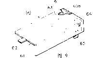
接下去,参阅图9说明本发明的第七实施例。图9示出了装了具有外部天线端子的小型片状环形天线的电池盖60。在这种情况下,同样,天线导体61在横截面呈L字形且一端有侧壁60a的电池盖60的内表面上形成。天线导体61具有无线电电路连接端子62和63和可用以装外部天线(图中未示出)的外部天线连接部分64。在这种情况下,为进一步提高灵敏度,外部天线装在天线导体61上。外部天线连接部分64通过外部天线连接端子65与外壳1中的无线电电路电连接。Next, referring to FIG. 9, a seventh embodiment of the present invention will be described. FIG. 9 shows the
接下去,参阅图10说明本发明的第八实施例。图10示出了装有具有外部接口的小型片状环形天线的电池盖70。在这种情况下,同样,天线导体71在横截面呈L字形且一端具有侧壁70a的电池盖70上形成,它具有无线电电路连接端子72和73。电池盖70侧壁上形成有外部接口部分74,供与外部装置交换通信数据用。外部接口部分74通过外壳1侧壁上的数据接插部分75与无线电电路连接。通过改变接口部分的形状,可以配置红外接口、卡槽接口等。Next, referring to FIG. 10, an eighth embodiment of the present invention will be described. FIG. 10 shows a battery cover 70 equipped with a small patch loop antenna with an external interface. In this case, too, an antenna conductor 71 is formed on a battery cover 70 having an L-shaped cross section and a side wall 70a at one end, which has radio circuit connection terminals 72 and 73 . An external interface portion 74 is formed on the side wall of the battery cover 70 for exchanging communication data with external devices. The external interface part 74 is connected with the radio circuit through the data socket part 75 on the side wall of the casing 1 . By changing the shape of the interface part, an infrared interface, a card slot interface, etc. can be configured.
Claims (9)
Translated fromChineseApplications Claiming Priority (3)
| Application Number | Priority Date | Filing Date | Title |
|---|---|---|---|
| JP349657/1996 | 1996-12-27 | ||
| JP8349657AJP2990083B2 (en) | 1996-12-27 | 1996-12-27 | Mobile communication antenna device |
| JP349657/96 | 1996-12-27 |
Publications (2)
| Publication Number | Publication Date |
|---|---|
| CN1190805Atrue CN1190805A (en) | 1998-08-19 |
| CN1114239C CN1114239C (en) | 2003-07-09 |
Family
ID=18405222
Family Applications (1)
| Application Number | Title | Priority Date | Filing Date |
|---|---|---|---|
| CN97126266AExpired - Fee RelatedCN1114239C (en) | 1996-12-27 | 1997-12-27 | Antenna device for mobile communication |
Country Status (3)
| Country | Link |
|---|---|
| US (1) | US6028555A (en) |
| JP (1) | JP2990083B2 (en) |
| CN (1) | CN1114239C (en) |
Cited By (8)
| Publication number | Priority date | Publication date | Assignee | Title |
|---|---|---|---|---|
| CN100461644C (en)* | 2005-05-25 | 2009-02-11 | 乐金电子(中国)研究开发中心有限公司 | Mobile communication terminal |
| US7532166B2 (en) | 2004-10-26 | 2009-05-12 | Samsung Electronics Co., Ltd | Antenna device for portable terminal |
| CN101944921A (en)* | 2009-07-06 | 2011-01-12 | Lg电子株式会社 | Portable terminal |
| US7890150B2 (en) | 2007-10-26 | 2011-02-15 | Wistron Corporation | Wireless communication device and antenna module thereof |
| CN101431542B (en)* | 2007-11-05 | 2012-03-21 | 纬创资通股份有限公司 | Mobile device and its miniature antenna replacement module |
| CN101442329B (en)* | 2007-06-21 | 2013-01-02 | 捷讯研究有限公司 | Mobile wireless communication device including conductive, electrically floating beamforming elements and related methods |
| CN101425679B (en)* | 2007-10-30 | 2014-12-10 | 三星Sdi株式会社 | Protective circuit module and secondary battery pack including the same |
| CN112018501A (en)* | 2020-08-31 | 2020-12-01 | 广东小天才科技有限公司 | Power supply device applied to wearable equipment and portable equipment |
Families Citing this family (58)
| Publication number | Priority date | Publication date | Assignee | Title |
|---|---|---|---|---|
| US6240301B1 (en)* | 1998-10-29 | 2001-05-29 | Ericcson Inc. | Diversity antenna in a SIM card package |
| KR100587276B1 (en)* | 1999-10-01 | 2006-06-08 | 엘지전자 주식회사 | Mobile Phones and Batteries in Mobile Phones |
| US6624760B1 (en)* | 2000-05-30 | 2003-09-23 | Sandia National Laboratories | Monitoring system including an electronic sensor platform and an interrogation transceiver |
| FR2811499B1 (en)* | 2000-07-10 | 2002-12-20 | Cit Alcatel | PORTABLE ELECTRONIC DEVICE PROVIDED WITH AN INTEGRATED RADIOCOMMUNICATION DEVICE INCLUDING AN ANTENNA FOR TRANSMITTING AND / OR RECEIVING ELECTROMAGNETIC WAVES |
| CN1486521A (en)* | 2000-12-14 | 2004-03-31 | Cavity antenna with reactive surface loading | |
| KR20020061103A (en)* | 2001-01-12 | 2002-07-22 | 후루까와덴끼고오교 가부시끼가이샤 | Antenna device and terminal with the antenna device |
| SE523715C2 (en)* | 2001-03-13 | 2004-05-11 | Gigaant Ab Ideon Science & Tec | Antenna device for mounting in an enclosure to an appliance as well as methods for making it |
| KR20010044821A (en)* | 2001-03-29 | 2001-06-05 | 전중수 | A handiphone with battery combined in antenna |
| KR20030093866A (en)* | 2002-06-05 | 2003-12-11 | 에스케이 텔레콤주식회사 | Battery Pack for Mobile Terminal with RF Antenna |
| GB0229141D0 (en)* | 2002-12-16 | 2003-01-15 | Splashpower Ltd | Improvements relating to contact-less power transfer |
| JPWO2005004342A1 (en)* | 2003-07-08 | 2006-08-17 | 富士通株式会社 | Communication terminal device and power supply method |
| JP4804724B2 (en)* | 2004-05-11 | 2011-11-02 | 株式会社アマダ | IC tag for mold mounting and mold |
| FR2863406B1 (en)* | 2003-12-09 | 2008-08-29 | Cit Alcatel | ANTENNA FOR RADIO TERMINAL |
| FR2872323B1 (en)* | 2004-06-24 | 2006-09-08 | Sagem | PORTABLE DEVICE WITH ANTENNA AND HOLDING A PRINTING MEDIUM |
| US20060017626A1 (en)* | 2004-07-12 | 2006-01-26 | Anand Kannan | Antenna module for mobile phone |
| JP2006067254A (en)* | 2004-08-26 | 2006-03-09 | Omron Corp | Radio communications equipment |
| JP2006191437A (en)* | 2005-01-07 | 2006-07-20 | Matsushita Electric Ind Co Ltd | Portable radio |
| GB0501170D0 (en)* | 2005-01-20 | 2005-03-02 | Antenova Ltd | A two-module integrated antenna and radio |
| KR100673254B1 (en) | 2005-03-03 | 2007-01-22 | 엘지전자 주식회사 | Mobile communication terminal with antenna on battery |
| JP2007006267A (en)* | 2005-06-24 | 2007-01-11 | Matsushita Electric Ind Co Ltd | Portable wireless device and foldable portable wireless device |
| DK176361B1 (en)* | 2005-08-12 | 2007-09-24 | Gn As | Communication unit with built-in antenna |
| US7408512B1 (en) | 2005-10-05 | 2008-08-05 | Sandie Corporation | Antenna with distributed strip and integrated electronic components |
| SE0600417L (en)* | 2006-02-24 | 2007-04-10 | Amc Centurion Ab | Antenna device, portable radio communication device comprising such an antenna device and a battery unit for a portable radio communication device |
| JP4783194B2 (en) | 2006-04-11 | 2011-09-28 | 富士通コンポーネント株式会社 | Portable device |
| US7538730B2 (en)* | 2006-04-26 | 2009-05-26 | Nokia Corporation | Antenna |
| GB2439601A (en)* | 2006-06-30 | 2008-01-02 | Nokia Corp | A moulded housing member with an integrated antenna element for a portable device |
| US7215600B1 (en) | 2006-09-12 | 2007-05-08 | Timex Group B.V. | Antenna arrangement for an electronic device and an electronic device including same |
| KR100819281B1 (en)* | 2006-10-30 | 2008-04-02 | 삼성전자주식회사 | Battery cover grounding device for portable terminals |
| US7623077B2 (en)* | 2006-12-15 | 2009-11-24 | Apple Inc. | Antennas for compact portable wireless devices |
| KR100843442B1 (en)* | 2007-01-02 | 2008-07-03 | 삼성전기주식회사 | Film type antenna and mobile communication terminal case using the same |
| US7573427B2 (en) | 2007-06-21 | 2009-08-11 | Research In Motion Limited | Mobile wireless communications device including electrically conductive, electrically floating beam shaping elements and related methods |
| JP5020000B2 (en)* | 2007-08-31 | 2012-09-05 | 株式会社オートネットワーク技術研究所 | In-vehicle wireless device |
| KR101404743B1 (en)* | 2007-09-12 | 2014-06-10 | 엘지전자 주식회사 | Portable terminal having antenna module and antenna setting method therefor |
| FR2923120B1 (en)* | 2007-10-31 | 2010-05-07 | Archos Sa | DEVICE FOR ENABLING A PORTABLE DEVICE TO RECEIVE AND / OR TRANSMIT RADIO FREQUENCY SIGNALS AND ASSOCIATED SYSTEM. |
| KR20090055783A (en)* | 2007-11-29 | 2009-06-03 | 삼성전자주식회사 | Antenna device of portable wireless terminal |
| CN101910968A (en)* | 2008-01-07 | 2010-12-08 | 捷通国际有限公司 | Wireless power adapter for computer |
| CN101257526B (en)* | 2008-04-07 | 2015-04-22 | Tcl天一移动通信(深圳)有限公司 | Combined battery cap lateral grounding structure of mobile communication terminal |
| US20090256766A1 (en)* | 2008-04-09 | 2009-10-15 | Bury Sp Z O.O. | Mobile phone antenna integrated with battery |
| KR101044994B1 (en) | 2008-06-20 | 2011-06-29 | 삼성전자주식회사 | Antenna device of mobile terminal |
| US20100016024A1 (en)* | 2008-07-21 | 2010-01-21 | Guangli Yang | Mobile Communications Device Diversity Antenna |
| JP4645993B2 (en)* | 2008-09-29 | 2011-03-09 | Tdk株式会社 | Wireless transmitter |
| KR101581221B1 (en)* | 2009-03-24 | 2015-12-30 | 삼성전자주식회사 | Battery cover structure and imaging device having the same |
| JP5208845B2 (en)* | 2009-04-24 | 2013-06-12 | 京セラ株式会社 | Portable electronic devices |
| TWI501615B (en)* | 2010-02-10 | 2015-09-21 | Htc Corp | Handheld device |
| CN102157775B (en)* | 2010-02-12 | 2015-01-21 | 宏达国际电子股份有限公司 | handheld device |
| US8583063B1 (en) | 2010-04-01 | 2013-11-12 | Sprint Communications Company L.P. | Antenna configuration selection by a wireless communication device |
| WO2012030010A1 (en)* | 2010-09-03 | 2012-03-08 | 엑스지 솔루션스 엘엘씨 | Antenna booster case for increasing transmission and reception sensitivity of a mobile device |
| US8791864B2 (en)* | 2011-01-11 | 2014-07-29 | Apple Inc. | Antenna structures with electrical connections to device housing members |
| KR101433669B1 (en)* | 2012-01-20 | 2014-08-25 | 주식회사 엘지화학 | Battery Module Having Planar Inverted-F Antenna |
| JP5980699B2 (en)* | 2013-02-20 | 2016-08-31 | シャープ株式会社 | Mobile device |
| US9711863B2 (en) | 2013-03-13 | 2017-07-18 | Microsoft Technology Licensing, Llc | Dual band WLAN coupled radiator antenna |
| JP2014187435A (en)* | 2013-03-21 | 2014-10-02 | Sharp Corp | Battery lid, battery housing case, and portable terminal |
| CN105827753A (en)* | 2016-03-18 | 2016-08-03 | 乐视移动智能信息技术(北京)有限公司 | Portable user terminal, protection sleeve applied to same and assembly part |
| JP2018133757A (en)* | 2017-02-17 | 2018-08-23 | 住友電装株式会社 | Electrical connection box with wireless reception function |
| CN110809837B (en)* | 2017-06-16 | 2022-04-29 | 雅马哈株式会社 | wireless communication device |
| RU2652168C1 (en) | 2017-09-07 | 2018-04-25 | Самсунг Электроникс Ко., Лтд. | Device for conversion of electromagnetic radiation into direct current |
| JP6881349B2 (en)* | 2018-02-26 | 2021-06-02 | 株式会社デンソー | Vehicle antenna device |
| JP7716164B2 (en)* | 2022-02-18 | 2025-07-31 | パナソニックオートモーティブシステムズ株式会社 | electronic equipment |
Family Cites Families (7)
| Publication number | Priority date | Publication date | Assignee | Title |
|---|---|---|---|---|
| JPS62232202A (en)* | 1986-04-02 | 1987-10-12 | Matsushita Electric Ind Co Ltd | Antenna system |
| JPH0798441B2 (en)* | 1988-09-06 | 1995-10-25 | 住友ゴム工業株式会社 | Tire and wheel rim assembly and tire used therefor |
| JPH04103006A (en)* | 1990-08-22 | 1992-04-06 | Otari Kk | Digital tape recorder |
| JPH07273685A (en)* | 1994-03-30 | 1995-10-20 | Canon Inc | Wireless device housing |
| JPH07321688A (en)* | 1994-05-25 | 1995-12-08 | Funai Denki Kenkyusho:Kk | Built-in antenna of radio equipment |
| US5649306A (en)* | 1994-09-16 | 1997-07-15 | Motorola, Inc. | Portable radio housing incorporating diversity antenna structure |
| JPH08265026A (en)* | 1995-03-27 | 1996-10-11 | Casio Comput Co Ltd | Portable radio |
- 1996
- 1996-12-27JPJP8349657Apatent/JP2990083B2/ennot_activeExpired - Fee Related
- 1997
- 1997-12-23USUS08/997,609patent/US6028555A/ennot_activeExpired - Fee Related
- 1997-12-27CNCN97126266Apatent/CN1114239C/ennot_activeExpired - Fee Related
Cited By (11)
| Publication number | Priority date | Publication date | Assignee | Title |
|---|---|---|---|---|
| US7532166B2 (en) | 2004-10-26 | 2009-05-12 | Samsung Electronics Co., Ltd | Antenna device for portable terminal |
| CN100461644C (en)* | 2005-05-25 | 2009-02-11 | 乐金电子(中国)研究开发中心有限公司 | Mobile communication terminal |
| CN101442329B (en)* | 2007-06-21 | 2013-01-02 | 捷讯研究有限公司 | Mobile wireless communication device including conductive, electrically floating beamforming elements and related methods |
| US7890150B2 (en) | 2007-10-26 | 2011-02-15 | Wistron Corporation | Wireless communication device and antenna module thereof |
| CN101425679B (en)* | 2007-10-30 | 2014-12-10 | 三星Sdi株式会社 | Protective circuit module and secondary battery pack including the same |
| CN101431542B (en)* | 2007-11-05 | 2012-03-21 | 纬创资通股份有限公司 | Mobile device and its miniature antenna replacement module |
| CN101944921A (en)* | 2009-07-06 | 2011-01-12 | Lg电子株式会社 | Portable terminal |
| US8406828B2 (en) | 2009-07-06 | 2013-03-26 | Lg Electronics Inc. | Mobile terminal |
| CN101944921B (en)* | 2009-07-06 | 2013-07-03 | Lg电子株式会社 | Mobile terminal |
| CN112018501A (en)* | 2020-08-31 | 2020-12-01 | 广东小天才科技有限公司 | Power supply device applied to wearable equipment and portable equipment |
| CN112018501B (en)* | 2020-08-31 | 2024-02-27 | 广东小天才科技有限公司 | Power supply device applied to wearable equipment and portable equipment |
Also Published As
| Publication number | Publication date |
|---|---|
| JPH10190331A (en) | 1998-07-21 |
| US6028555A (en) | 2000-02-22 |
| CN1114239C (en) | 2003-07-09 |
| JP2990083B2 (en) | 1999-12-13 |
Similar Documents
| Publication | Publication Date | Title |
|---|---|---|
| CN1114239C (en) | Antenna device for mobile communication | |
| US8593360B2 (en) | Slotted ground-plane used as a slot antenna or used for a PIFA antenna | |
| US8098204B2 (en) | Mobile communication terminal | |
| JP3114605B2 (en) | Surface mount antenna and communication device using the same | |
| EP1098387B1 (en) | Mobile communication antenna and mobile communication apparatus using it | |
| US6946996B2 (en) | Antenna apparatus, printed wiring board, printed circuit board, communication adapter and portable electronic equipment | |
| US6285327B1 (en) | Parasitic element for a substrate antenna | |
| US6259407B1 (en) | Uniplanar dual strip antenna | |
| US6972723B2 (en) | Wide-band antenna | |
| JP2001111321A (en) | Antenna device and communication terminal equipment | |
| KR100649791B1 (en) | Board antenna with elements to prevent energy coupling between antenna and conductors | |
| JP2009055617A (en) | Substrate antenna | |
| EP1648050A1 (en) | Dual-band chip antenna module | |
| JP4379004B2 (en) | Communication adapter and portable electronic device | |
| CN100399625C (en) | Concealed antenna | |
| JP2000031721A (en) | Built-in antenna system | |
| CN1706076A (en) | Antenna and portable radio using same | |
| US20090303151A1 (en) | Low profile gps antenna assembly | |
| US20080062060A1 (en) | Antenna and receiver having the same | |
| JP3275513B2 (en) | Mobile communication equipment | |
| JP2005020766A (en) | Portable radio | |
| JP2002305461A (en) | Wireless communication module | |
| CN1839513B (en) | Placing of components on an antenna arrangement | |
| JPH10256819A (en) | Radios and radio systems | |
| JP2006049978A (en) | Portable radio |
Legal Events
| Date | Code | Title | Description |
|---|---|---|---|
| C06 | Publication | ||
| PB01 | Publication | ||
| C10 | Entry into substantive examination | ||
| SE01 | Entry into force of request for substantive examination | ||
| C14 | Grant of patent or utility model | ||
| GR01 | Patent grant | ||
| C19 | Lapse of patent right due to non-payment of the annual fee | ||
| CF01 | Termination of patent right due to non-payment of annual fee |