CN1190500A - Motor and process for producing the same - Google Patents
Motor and process for producing the sameDownload PDFInfo
- Publication number
- CN1190500A CN1190500ACN97190480ACN97190480ACN1190500ACN 1190500 ACN1190500 ACN 1190500ACN 97190480 ACN97190480 ACN 97190480ACN 97190480 ACN97190480 ACN 97190480ACN 1190500 ACN1190500 ACN 1190500A
- Authority
- CN
- China
- Prior art keywords
- circuit board
- motor
- motor according
- connector
- resin
- Prior art date
- Legal status (The legal status is an assumption and is not a legal conclusion. Google has not performed a legal analysis and makes no representation as to the accuracy of the status listed.)
- Granted
Links
- 238000000034methodMethods0.000titleclaimsdescription10
- 229920005989resinPolymers0.000claimsabstractdescription102
- 239000011347resinSubstances0.000claimsabstractdescription102
- 229910052751metalInorganic materials0.000claimsabstractdescription44
- 239000002184metalSubstances0.000claimsabstractdescription44
- 238000004519manufacturing processMethods0.000claimsabstractdescription16
- 230000002093peripheral effectEffects0.000claimsdescription20
- XEEYBQQBJWHFJM-UHFFFAOYSA-NIronChemical class[Fe]XEEYBQQBJWHFJM-UHFFFAOYSA-N0.000claimsdescription12
- 239000000463materialSubstances0.000claimsdescription10
- 238000009434installationMethods0.000claimsdescription8
- 238000009413insulationMethods0.000claimsdescription8
- 238000003825pressingMethods0.000claimsdescription6
- 238000003780insertionMethods0.000claimsdescription3
- 230000037431insertionEffects0.000claimsdescription3
- 238000005476solderingMethods0.000claimsdescription2
- 238000004804windingMethods0.000claimsdescription2
- 238000009826distributionMethods0.000claims2
- 230000003014reinforcing effectEffects0.000claims2
- 230000015572biosynthetic processEffects0.000claims1
- 238000007493shaping processMethods0.000claims1
- 238000000465mouldingMethods0.000abstractdescription21
- 230000017525heat dissipationEffects0.000description20
- 239000003990capacitorSubstances0.000description15
- 238000001816coolingMethods0.000description12
- 229910000679solderInorganic materials0.000description9
- 238000002788crimpingMethods0.000description7
- 239000007769metal materialSubstances0.000description7
- 229910052782aluminiumInorganic materials0.000description6
- XAGFODPZIPBFFR-UHFFFAOYSA-NaluminiumChemical compound[Al]XAGFODPZIPBFFR-UHFFFAOYSA-N0.000description6
- 238000001514detection methodMethods0.000description6
- RYGMFSIKBFXOCR-UHFFFAOYSA-NCopperChemical compound[Cu]RYGMFSIKBFXOCR-UHFFFAOYSA-N0.000description5
- 229910052802copperInorganic materials0.000description5
- 239000010949copperSubstances0.000description5
- 238000002347injectionMethods0.000description5
- 239000007924injectionSubstances0.000description5
- WABPQHHGFIMREM-UHFFFAOYSA-Nlead(0)Chemical compound[Pb]WABPQHHGFIMREM-UHFFFAOYSA-N0.000description5
- 229920001225polyester resinPolymers0.000description4
- 239000004645polyester resinSubstances0.000description4
- 229910000838Al alloyInorganic materials0.000description3
- 230000005540biological transmissionEffects0.000description3
- 230000000694effectsEffects0.000description3
- 238000007667floatingMethods0.000description3
- 229910001369BrassInorganic materials0.000description2
- 229910000881Cu alloyInorganic materials0.000description2
- 229910000976Electrical steelInorganic materials0.000description2
- 230000009286beneficial effectEffects0.000description2
- 239000010951brassSubstances0.000description2
- 239000004020conductorSubstances0.000description2
- 238000006073displacement reactionMethods0.000description2
- 238000010438heat treatmentMethods0.000description2
- 229910052761rare earth metalInorganic materials0.000description2
- 238000007789sealingMethods0.000description2
- XLYOFNOQVPJJNP-UHFFFAOYSA-NwaterSubstancesOXLYOFNOQVPJJNP-UHFFFAOYSA-N0.000description2
- KXGFMDJXCMQABM-UHFFFAOYSA-N2-methoxy-6-methylphenolChemical compound[CH]OC1=CC=CC([CH])=C1OKXGFMDJXCMQABM-UHFFFAOYSA-N0.000description1
- ZOXJGFHDIHLPTG-UHFFFAOYSA-NBoronChemical compound[B]ZOXJGFHDIHLPTG-UHFFFAOYSA-N0.000description1
- BPQQTUXANYXVAA-UHFFFAOYSA-NOrthosilicateChemical compound[O-][Si]([O-])([O-])[O-]BPQQTUXANYXVAA-UHFFFAOYSA-N0.000description1
- 230000006750UV protectionEffects0.000description1
- 229910052770UraniumInorganic materials0.000description1
- 229920001807Urea-formaldehydePolymers0.000description1
- 239000000853adhesiveSubstances0.000description1
- 230000001070adhesive effectEffects0.000description1
- 230000002457bidirectional effectEffects0.000description1
- 229910052796boronInorganic materials0.000description1
- 239000004927claySubstances0.000description1
- 229910052570clayInorganic materials0.000description1
- 238000002485combustion reactionMethods0.000description1
- 239000000470constituentSubstances0.000description1
- 238000010276constructionMethods0.000description1
- 238000007796conventional methodMethods0.000description1
- 230000005347demagnetizationEffects0.000description1
- 239000000428dustSubstances0.000description1
- 239000013013elastic materialSubstances0.000description1
- 229920001971elastomerPolymers0.000description1
- 230000005611electricityEffects0.000description1
- 238000005516engineering processMethods0.000description1
- 230000005284excitationEffects0.000description1
- 238000000605extractionMethods0.000description1
- 239000000945fillerSubstances0.000description1
- 230000002452interceptive effectEffects0.000description1
- 239000007788liquidSubstances0.000description1
- 238000002844meltingMethods0.000description1
- 230000008018meltingEffects0.000description1
- 239000010445micaSubstances0.000description1
- 229910052618mica groupInorganic materials0.000description1
- 239000003921oilSubstances0.000description1
- 230000000149penetrating effectEffects0.000description1
- 229920001568phenolic resinPolymers0.000description1
- 239000005011phenolic resinSubstances0.000description1
- 229920000728polyesterPolymers0.000description1
- -1polyethylene terephthalatePolymers0.000description1
- 229920000139polyethylene terephthalatePolymers0.000description1
- 239000005020polyethylene terephthalateSubstances0.000description1
- 230000000191radiation effectEffects0.000description1
- 150000002910rare earth metalsChemical class0.000description1
- 229910052710siliconInorganic materials0.000description1
- 239000010703siliconSubstances0.000description1
- 239000010935stainless steelSubstances0.000description1
- 229910001220stainless steelInorganic materials0.000description1
- 239000000454talcSubstances0.000description1
- 229910052623talcInorganic materials0.000description1
- 229920005992thermoplastic resinPolymers0.000description1
- 229920001187thermosetting polymerPolymers0.000description1
- 229910052723transition metalInorganic materials0.000description1
- 150000003624transition metalsChemical class0.000description1
- 238000003466weldingMethods0.000description1
Images


Classifications
- H—ELECTRICITY
- H02—GENERATION; CONVERSION OR DISTRIBUTION OF ELECTRIC POWER
- H02K—DYNAMO-ELECTRIC MACHINES
- H02K29/00—Motors or generators having non-mechanical commutating devices, e.g. discharge tubes or semiconductor devices
- H02K29/06—Motors or generators having non-mechanical commutating devices, e.g. discharge tubes or semiconductor devices with position sensing devices
- H02K29/08—Motors or generators having non-mechanical commutating devices, e.g. discharge tubes or semiconductor devices with position sensing devices using magnetic effect devices, e.g. Hall-plates, magneto-resistors
- H—ELECTRICITY
- H02—GENERATION; CONVERSION OR DISTRIBUTION OF ELECTRIC POWER
- H02K—DYNAMO-ELECTRIC MACHINES
- H02K11/00—Structural association of dynamo-electric machines with electric components or with devices for shielding, monitoring or protection
- H02K11/30—Structural association with control circuits or drive circuits
- H02K11/33—Drive circuits, e.g. power electronics
- H—ELECTRICITY
- H02—GENERATION; CONVERSION OR DISTRIBUTION OF ELECTRIC POWER
- H02K—DYNAMO-ELECTRIC MACHINES
- H02K5/00—Casings; Enclosures; Supports
- H02K5/04—Casings or enclosures characterised by the shape, form or construction thereof
- H02K5/08—Insulating casings
- H—ELECTRICITY
- H02—GENERATION; CONVERSION OR DISTRIBUTION OF ELECTRIC POWER
- H02K—DYNAMO-ELECTRIC MACHINES
- H02K5/00—Casings; Enclosures; Supports
- H02K5/04—Casings or enclosures characterised by the shape, form or construction thereof
- H02K5/22—Auxiliary parts of casings not covered by groups H02K5/06-H02K5/20, e.g. shaped to form connection boxes or terminal boxes
- H02K5/225—Terminal boxes or connection arrangements
- H—ELECTRICITY
- H02—GENERATION; CONVERSION OR DISTRIBUTION OF ELECTRIC POWER
- H02K—DYNAMO-ELECTRIC MACHINES
- H02K2211/00—Specific aspects not provided for in the other groups of this subclass relating to measuring or protective devices or electric components
- H02K2211/03—Machines characterised by circuit boards, e.g. pcb
Landscapes
- Engineering & Computer Science (AREA)
- Power Engineering (AREA)
- Microelectronics & Electronic Packaging (AREA)
- Motor Or Generator Frames (AREA)
- Brushless Motors (AREA)
Abstract
Translated fromChineseDescription
Translated fromChinese技术领域technical field
本发明涉及作为譬如电动小型摩托车、电动汽车等具有电动机的装置的驱动源使用的电动机及其制造方法。The present invention relates to a motor used as a drive source of a device having a motor such as an electric scooter, an electric car, and a method for manufacturing the same.
背景技术Background technique
近年来,正在开发电动小型摩托车、电动汽车等不使用内燃机的车辆。作为这类车辆的驱动源使用的电动机,为了保护其内部装置,是安装于金属制的壳体内使用的。In recent years, vehicles that do not use internal combustion engines, such as electric scooters and electric cars, are being developed. An electric motor used as a drive source of such a vehicle is mounted in a metal case for use in order to protect its internal devices.
这类壳体由铝等金属制的壳体和盖体构成,在把电动机的组成构件装于壳体内后,盖上盖体,并且用螺栓将壳体与盖体组装为一体。在这种场合,对电动机的驱动进行控制的控制系统是设置在壳体的外部。This type of housing is composed of a metal housing such as aluminum and a cover. After the components of the motor are installed in the housing, the cover is covered, and the housing and the cover are assembled with bolts. In this case, a control system for controlling the driving of the motor is provided outside the casing.
然而,由于这类构造的电动机一般是把控制系统设置在壳体的外部,故会产生以下问题。However, since the motor of this type of construction generally has the control system disposed outside the casing, the following problems arise.
当把电动机安装在譬如小型摩托车本体上时,电动机的安装和控制系统的安装必须分开进行。而且必须用电缆在它们之间正确地接线,故作业十分复杂。When mounting the motor on, for example, a scooter body, the mounting of the motor and the mounting of the control system must be performed separately. Furthermore, it is necessary to correctly connect them with cables, so that the work is very complicated.
而且由于必须把电动机和控制系统分开设置,故需要留出设置电动机的空间、设置控制系统的空间、以及设置接线用电缆的空间。Furthermore, since the motor and the control system must be installed separately, it is necessary to reserve a space for installing the motor, a space for installing the control system, and a space for installing cables for wiring.
特别是,由于控制系统中也有发热体,故除了设置电动机用的散热部(散热器)外,还要设置控制系统用的散热部,这样就需要相当大的空间。In particular, since the control system also has a heating element, a heat dissipation unit (radiator) for the motor must be provided as well as a heat dissipation unit for the control system, requiring a considerable space.
而且当安装在前述小型摩托车本体上时,在小型摩托车行驶过程中等,连接电动机与控制系统的电缆容易发生破损。And when being installed on the aforementioned scooter body, the cable connecting the motor and the control system is prone to damage during the scooter running process, etc.
另一方面,曾考虑过不用金属制的组装壳体,而是把电动机整体用树脂进行模压,并把该模压树脂作为壳体。然而在这种场合,由于采用了树脂,会导致散热性恶化,同时机械性强度也会降低。On the other hand, it has been considered to mold the entire motor with resin instead of a metal assembly case, and to use the molded resin as the case. However, in this case, since the resin is used, the heat dissipation is deteriorated, and the mechanical strength is also reduced.
因此,本发明的目的在于提供一种组装及安装容易、小型、且可靠性强的电动机及其制造方法。Therefore, an object of the present invention is to provide a small and reliable electric motor that is easy to assemble and install, and a method for manufacturing the same.
发明的公开disclosure of invention
本发明的电动机把具有定子和转子的驱动系统和控制该驱动系统并具有电路板的控制系统安装于壳体内,其特点是,在所述壳体内还设有供向所述控制系统输入的电源电流流通的第1导电销、供从所述控制系统向线圈各相输出的电流流通的第2导电销,并通过所述第1导电销和第2导电销支撑所述电路板。The electric motor of the present invention installs the drive system with the stator and the rotor and the control system that controls the drive system and has a circuit board in the casing, and it is characterized in that a power supply for inputting to the control system is also provided in the casing. The first conductive pin through which the current flows, the second conductive pin through which the current output from the control system to each phase of the coil flows, and the circuit board is supported by the first conductive pin and the second conductive pin.
本发明与分开设置对电路板固定用的构件、对电源与控制系统作电气连接用的电缆的场合相比,可以减少零件数量,且可减少所需的设置空间。因此,可实现电动机的小型化,且由于可从一个方向安装和固定零件,既有利于组装作业自动化,也使组装更加容易。The present invention can reduce the number of parts and the required installation space compared with the case where the components for fixing the circuit board and the cables for electrically connecting the power supply and the control system are provided separately. Therefore, the miniaturization of the motor can be achieved, and since the parts can be mounted and fixed from one direction, it is not only conducive to the automation of the assembly work, but also makes the assembly easier.
另外,本发明的电动机把具有定子和转子的驱动系统和控制该驱动系统并具有电路板的控制系统安装于壳体内,其特点是,所述控制系统具有电路板、设置在该电路板上且呈环状配置的多个开关元件。In addition, in the electric motor of the present invention, a drive system having a stator and a rotor and a control system controlling the drive system and having a circuit board are installed in the casing, and the characteristic is that the control system has a circuit board, is arranged on the circuit board and A plurality of switching elements arranged in a ring.
由于可在狭小的空间内设置多个开关元件,故可缩小电路板面积,可在不增加浪涌电压的条件下实现控制系统小型化,进而实现电动机小型化。Since multiple switching elements can be installed in a small space, the area of the circuit board can be reduced, and the miniaturization of the control system can be realized without increasing the surge voltage, thereby realizing the miniaturization of the motor.
本发明的电动机制造方法使用在分型面接合的第1金属模及第2金属模、及插入所述第1和第2金属模的中心部的第3金属模,在由这些第1、第2及第3金属模构成的型腔内插入电动机的定子、金属制的筒体及埋设构件并加以固定,然后注入熔融树脂并进行树脂模压而构成电动机。The motor manufacturing method of the present invention uses the first metal mold and the second metal mold joined at the parting surface, and the third metal mold inserted into the center of the first and second metal molds. The stator of the electric motor, the metal cylinder, and the embedding member are inserted and fixed in the cavity formed by the second and third metal molds, and then molten resin is injected and resin-molded to form the electric motor.
由于本发明能把电动机的定子等可靠地埋设于由金属模决定的位置,故当在这些埋设部分安装销子或电路板等其他零件时可提高安装精度。还由于具备金属制的筒体,故可用该筒体加强安装部等需要一定强度的部位。例如,是在埋设构件上配置电动机驱动或传感器的线后再进行模压并制作连接器的,故无需在引出配线的位置设置分型面,从而无需对模具进行复杂的分型,可降低成本。Since the present invention can reliably embed the stator and the like of the motor at the positions determined by the metal mold, when installing other parts such as pins or circuit boards on these embedded parts, the mounting accuracy can be improved. Also, since it has a metal cylinder, the cylinder can be used to reinforce parts that require a certain strength, such as the mounting part. For example, the wiring of the motor drive or the sensor is placed on the embedded component, and then the connector is molded and manufactured, so there is no need to set a parting surface at the position where the wiring is drawn out, so that there is no need for complicated parting of the mold, which can reduce costs. .
对附图的简单说明A brief description of the attached drawings
图1是把本发明的电动机用于电动摩托车用电动机时的实施例的剖面侧视图。Fig. 1 is a sectional side view of an embodiment in which the motor of the present invention is used for an electric motorcycle motor.
图2是图1所示电动机的俯视图。Fig. 2 is a top view of the motor shown in Fig. 1 .
图3是取下了盖体及控制系统后的电动机的俯视图。Fig. 3 is a top view of the motor with the cover and the control system removed.
图4是图1所示电动机的仰视图。Fig. 4 is a bottom view of the motor shown in Fig. 1 .
图5是取下了盖构件及转子后的电动机的仰视图。Fig. 5 is a bottom view of the motor with the cover member and the rotor removed.
图6是取下了盖构件、转子及电路板后的电动机的仰视图。Fig. 6 is a bottom view of the motor with a cover member, a rotor, and a circuit board removed.
图7是电路板(第1电路板)及设置于该电路板上的开关元件的俯视图。7 is a plan view of a circuit board (first circuit board) and switching elements provided on the circuit board.
图8是把固定构件做成树脂成形体后设置在电路板上的状态图。Fig. 8 is a view showing a state in which a fixing member is formed into a resin molded body and installed on a circuit board.
图9是固定构件构造示例的俯视图。Fig. 9 is a top view of a configuration example of a fixing member.
图10是在图9所示的固定构件上设置各开关元件时的俯视图。Fig. 10 is a plan view when each switching element is provided on the fixing member shown in Fig. 9 .
图11是沿图10中A-A线的剖视图。Fig. 11 is a sectional view along line A-A in Fig. 10 .
图12是沿图10中B-B线的剖视图。Fig. 12 is a sectional view along line B-B in Fig. 10 .
图13是在电路板(第1电路板)上设置图10所示的固定构件时的俯视图。Fig. 13 is a plan view when the fixing member shown in Fig. 10 is installed on a circuit board (first circuit board).
图14是沿图13中C-C线的剖视图。Fig. 14 is a sectional view along line C-C in Fig. 13 .
图15是电路板(第2电路板)的仰视图。Fig. 15 is a bottom view of a circuit board (second circuit board).
图16是电路板的仰视图。Figure 16 is a bottom view of the circuit board.
图17是电路板的侧视图。Fig. 17 is a side view of the circuit board.
图18是嵌入式螺母构造示例的侧视图。Figure 18 is a side view of an example of an embedded nut configuration.
图19是在嵌入式螺母上配线后的侧视图。Fig. 19 is a side view after wiring on the embedded nut.
图20是端子构件及连接器构造示例的分解立体图。Fig. 20 is an exploded perspective view of a configuration example of a terminal member and a connector.
图21表示在连接器上配线后的定子。Fig. 21 shows the stator after wiring on the connector.
图22是用销子及可动销夹持端子构件平板部的构造示例的分解立体图。Fig. 22 is an exploded perspective view of an example of a structure in which a flat plate portion of a terminal member is held between a pin and a movable pin.
图23是端子构件及连接器其他构造示例的分解立体图。Fig. 23 is an exploded perspective view of another configuration example of a terminal member and a connector.
图24是表示本发明的电动机制造方法的剖视图。Fig. 24 is a sectional view showing a method of manufacturing a motor according to the present invention.
实施发明的最佳形态The best form for carrying out the invention
以下结合附图所示的最佳实施例详细说明本发明的电动机及其制造方法。为了便于说明,把图1、图18、图20、图24中的下侧称为“底端”,上侧称为“顶端”,上下方向称为“轴向”。The electric motor and its manufacturing method of the present invention will be described in detail below in conjunction with the preferred embodiments shown in the accompanying drawings. For ease of description, the lower side in Fig. 1, Fig. 18, Fig. 20, and Fig. 24 is called "bottom end", the upper side is called "top end", and the up and down direction is called "axial direction".
如图1到图6所示,本实施例的电动机1为无刷DC电动机,是把由定子10和转子14构成的电动机以及对该电动机的驱动进行控制的控制系统20容纳于壳体2内而构成。As shown in FIGS. 1 to 6 , the motor 1 of this embodiment is a brushless DC motor, and a motor composed of a
在本实施例中,前述定子10的线圈(励磁线圈)12如后所述,是由U相(第1相)、V相(第2相)及W相(第3相)构成的3相线圈。In this embodiment, the coil (excitation coil) 12 of the
壳体2主要由安装于后述的定子10外周的金属制筒体3、树脂成形部4、与筒体3的顶端一侧连接的金属制盖体5、及安装在树脂成形部4底端部的盖构件6构成。其中,通过用树脂将筒体3和定子10进行模压而形成树脂成形部4。在这种场合,定子10的大部分埋入树脂成形部4内,筒体3的顶端及底端与树脂成形部4卡合而固定在该树脂成形部4上。The
构成树脂成形部4的树脂可用热塑性树脂、热固性树脂中的任一种,譬如聚酯树脂、酚醛树脂、尿素树脂等硬质树脂。其中最理想的树脂是线膨胀系数小于筒体3的金属材料或尽量接近铁心11的金属材料、有利于吸收振动和噪音、成形性好、且具有足够强度和耐久性,而从这些要求出发,选用聚酯树脂尤为合适。The resin constituting the
在筒体3的外周,形成多个(图中为6个)轴向延伸的肋31,如图4到图6所示,各肋31的底端部构成把无刷DC电动机1安装在小型摩托车本体上用的安装部。即,在各肋31的底端部形成螺纹孔32,供把无刷DC电动机1安装于小型摩托车本体(未图示)时用的未图示螺栓(螺旋构件)与之螺纹结合。这样,当把无刷DC电动机1安装于小型摩托车本体时,由于是经过机械强度高的金属制筒体3上形成的安装部而进行安装的,故安装强度高,且不会在壳体2一侧发生破损。On the outer periphery of the
另外,如图3所示,在各个肋31的顶端部形成螺纹孔33。该螺纹孔33供把盖体5与筒体3连接、固定用的螺栓(螺旋构件)52与之螺纹结合。又如图2所示,在形成于盖体5外周部的凸缘53内插入螺栓52,并把各螺栓52旋入对应的螺纹孔33内,从而把筒体3与盖体5连接、固定。In addition, as shown in FIG. 3 , screw holes 33 are formed at the tip ends of the
另外,在筒体3的内侧形成一对轴向延伸的槽34。在该槽34内插入贯穿筒体3的底端到顶端的导电杆(初级端子)35,并用树脂进行模压。In addition, a pair of axially extending
这一对导电杆35作为向后述的定子10的线圈12通电用的初级端子、即把来自电源(未图示)的电力向后述的控制系统20供给用的路径起作用,比筒体3的底端更向底端一侧伸出,而且导电杆35的底端露出树脂成形部4的表面。在这种场合,在导电杆35的底端部、即在导电杆35的与后述旋转轴15的伸出端相同一侧的端部,形成与电源接线的端子(接线端子)351。The pair of
如上所述,本实施例的无刷DC电动机1是把来自电源的电力经过导电杆35而向控制系统20供给的,故与用电缆构成从电源到控制系统20的供电路径的场合相比,本发明组装容易,而且可防止振动等导致的供电路径损伤或断线。而且与用电缆形成供电路径的场合相比,电力损耗小。As mentioned above, the brushless DC motor 1 of the present embodiment supplies the power from the power supply to the
另外,由于导电杆35的端子351设置在与旋转轴15的凸出端相同的一侧,故从电源到端子351的配线可在小型摩托车本体内(CVT壳体内)进行。因此,配线不会暴露在外部,不易受到损伤,可靠性高。In addition, since the
而且,无刷DC电动机1无需在电源的输出端与控制系统20的输入端之间另外设置把电源与控制系统20进行电气接线的端子座。从而有利于无刷DC电动机1的小型化。Furthermore, the brushless DC motor 1 does not need to separately provide a terminal block for electrically connecting the power supply and the
另外,在筒体3和导电杆35之间设置了把筒体3与导电杆35绝缘用的绝缘层36。该绝缘层36也可用树脂模压方法形成。In addition, an insulating
前述筒体3用譬如铝或铝合金、铜或铜合金、不锈钢等金属材料构成。当用铝或铝合金构成筒体3时,筒体3的线膨胀系数比树脂或铁心11还大。从而,在进行树脂模压时,如后所述,一旦使金属模温度上升,筒体3与铁心11之间即形成间隙,熔融后的树脂即进入该间隙。一旦把完成的壳体2冷却,筒体3便要缩小,但因树脂已经进入,故不能完全缩小,在这种状态下,筒3与树脂成形部4之间的接触压力增加。其结果是,筒体3可靠地固定在树脂成形部4上,故就这一点而言,最好用铝或铝合金构成前述筒体3。The
另外,导电杆35及后述的销子25、26用铜或铜合金构成,而从提高电动机效率的目的出发,最好用无氧铜构成。In addition, the
如上所述,筒体3是用金属材料构成的,因此可以增强树脂成形部4,且可确保壳体2整体具有足够强度,同时具有很好的导热性和散热性。散热性好可以抑制电动机温度上升导致的磁铁减磁,故可以保持电动机的高性能。As mentioned above, the
由于电动机的驱动而产生的热量从定子10传递到筒体3,有一部分向大气中散发,其余部分传递到盖体5。盖体5位于壳体2的覆盖后述控制系统20的部分。而且该盖体5的顶端部具有多个散热片51,传递到盖体5的热量经过各散热片51而向大气中散发。The heat generated by the driving of the motor is transferred from the
通过设置这样的散热片51,可增加壳体2的表面积,进一步提高散热性,从而可有效地冷却电动机及壳体2。特别是当小型摩托车行驶时,气流接触散热片51的表面而可实行空气冷却。By providing
在本实施例中,只是在盖体5上设置散热片51即可得到足够的电动机冷却效果,而万一冷却效果不足时,在筒体3上也可设置同样的散热片。In this embodiment, sufficient cooling effect of the motor can be obtained only by arranging the cooling
在该无刷DC电动机1上,如前所述,盖体5兼作散热部,故与分别构成盖体和散热部的场合相比,本发明可减少零件数量,从而更便于制造。In this brushless DC motor 1, as mentioned above, the
而且如后所述,该散热部还兼作控制系统20的散热部。也就是说,在本实施例中,电动机的散热部和控制系统20的散热部是共用的,故有利于无刷DC电动机1的小型化。Furthermore, as will be described later, this heat dissipation unit also serves as a heat dissipation unit of the
另外,当树脂成形部4露出表面时,由于该树脂在耐水性、耐油性、耐紫外线等方面的问题而难以适应使用环境。然而,本实施例的无刷DC电动机1的筒体3和盖体5是用金属材料构成的,故当用筒体3的肋31底端部安装在小型摩托车本体上时,外周全部被金属材料覆盖。作为覆盖外周的金属材料,譬如使用压铸铝ADC12等传统的卓有成效的移动体用材料,即可解决适应使用环境的问题。In addition, when the resin molded
在被盖体5包围的空间内,容纳着对电动机的驱动进行控制的控制系统20。以下先说明控制系统20的第1构造示例。In the space surrounded by the
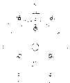
控制系统20主要由以下部分构成:相面对设置的圆盘状电路板(第1电路板)21及电路板(第2电路板)22、设置在电路板21的底端一侧的2个电解电容器23、设置在电路板21顶端一侧且构成反相电路的6个开关元件(功率元件)24、对前述反相电路的驱动进行控制的未图示的反相控制电路(设置在电路板21或电路板22上)、未图示的电源电路(设置在电路板21或电路板22上)。The
另外,本实施例是用3个MOSFET构成前述开关元件24的1个单位,反相控制电路根据规定的通电图形而将6个开关元件24中的1个正极开关元件24和1个负极开关元件24分别接通(含PWM控制),并依次向U相、V相及W相中的2相通电(进行3相的双向驱动)。这样便在定子10上形成旋转磁场,转子14旋转。In addition, in the present embodiment, three MOSFETs are used to constitute one unit of the
在图7中,各开关元件24分别设置在电路板21顶端一侧的外周部。在这种场合,开关元件24排成六角形的环状(大致圆周状)。In FIG. 7 , each switching
各开关元件24分别具有向一端伸出的端子群(臂部)241,端子群241设置成交替朝向内周和外周的状态。即,把端子群241向内周设置的开关元件24与端子群241向外周设置的开关元件24交替排列。Each switching
另外,在6个开关元件24中的1个与电路板21之间设置可对开关元件24的温度进行检测的温度传感器(热敏电阻)80。In addition, a temperature sensor (thermistor) 80 capable of detecting the temperature of the switching
这样,由于无刷DC电动机1的开关元件24排列成六角形的环状,故可以使与U相、V相及W相有关的电路板21上的各导线长度全部大致相等,这样便可降低浪涌电压。In this way, since the switching
而且各开关元件24是排列成其端子群241交替朝向内周和朝向外周的状态,故可以在各相邻的开关元件24不与散热板接触而保持绝缘的状态下尽量靠近内周一侧。也就是说,可以把开关元件24设置在较小的空间内,这样可以缩小电路板21。从而可在不增加浪涌电压的条件下实现控制系统20的小型化,进而实现无刷DC电动机1的小型化。Moreover, each switching
另外,由于设置了温度传感器80,故可对发热体、即开关元件24的温度进行检测。在这种场合,是对开关元件24的温度直接进行检测的,故可提高温度检测的精度。In addition, since the
而且,根据该温度传感器80的检测值对电动机的驱动进行控制,由此而抑制开关元件24的温度上升。通过这一控制可以提高无刷DC电动机1的可靠性。Then, the drive of the motor is controlled based on the detection value of the
如图1所示,在各开关元件24的上侧面(顶端面)、即在各开关元件24的上侧面与盖体5的顶端部内面之间分别设置覆盖其上侧面的全部或一部分的散热片29。As shown in FIG. 1 , on the upper side (top end surface) of each switching
该散热片29用导热系数高、具有绝缘性及弹性的材料构成。从而,通过设置该散热片29,能将从开关元件24产生的热量可靠地传递给盖体5,由此而提高冷却效率,另外,在使开关元件24与盖体5之间绝缘的同时,还可防止振动等导致的开关元件24受损。The
作为散热片29的构成材料,譬如可用硅、云母、粘土、滑石之类的硅酸盐、聚对苯二甲酸乙二醇酯(例如商品名称为聚酯树脂)、及其他各种聚酯等。As the constituent material of the
散热片29的厚度为0.2~1.0mm,最好是0.4~0.8mm。如果散热片29的厚度在此范围内,在把电路板21安装在后述的销子25、26上时产生的轴向组装公差即可被散热片29的弹性吸收,能更加可靠地把开关元件24压向盖体5。从而,能更加可靠地把开关元件24产生的热量传递给盖体5,更加可靠地保证开关元件24与盖体5之间的绝缘,同时能更加可靠地防止振动等导致的开关元件24受损。The thickness of the
下面说明控制系统20的第2构造示例。说明时省略与前述的控制系统20第1构造示例的相同之处,主要是说明不同点。Next, a second configuration example of the
控制系统20如图1所示,主要由以下部分构成:相面对设置的圆盘状电路板(第1电路板)21及圆盘状电路板(第2电路板)22、设置在电路板21底端一侧的2个电解电容器23、固定构件30(参照图13)、通过该固定构件30而设置在电路板21顶端一侧且构成反相电路的6个开关元件(功率元件)24、对前述反相电路的驱动进行控制的未图示的反相控制电路(设置在电路板21或电路板22上)、未图示的电源电路(设置在电路板21或电路板22上)。As shown in Figure 1, the
如图9到图14所示,固定构件30整体呈大致正六角形的环状。As shown in FIGS. 9 to 14 , the fixing
在固定构件30的6个边部301分别设有开关元件24定位用的阶梯部302,在6个角部303分别设有贯通孔304,可供固定构件30固定用的螺纹构件311插入。The six
另外,在这些边部301中1个的内周一侧设有载放部305,用于设置可检测开关元件24温度的温度传感器(热敏电阻)80。In addition, on the inner peripheral side of one of these
如图10、图11及图12所示,固定构件30的载放部305上设有温度传感器80,在各边部301上分别设置开关元件24,这样即把开关元件24排列成六角形的环状(大致圆周状)。As shown in Fig. 10, Fig. 11 and Fig. 12, a
在这种场合,开关元件24排列成端子群241交替朝向内周和外周的状态。也就是说,端子群241朝向内周设置的开关元件24与端子群241朝向外周设置的开关元件24交替排列。In this case, the switching
如图13和图14所示,该固定构件30用螺纹构件311固定在电路板21顶端一侧的外周部,这样各开关元件24便通过固定构件30而设置在电路板21的外周部。As shown in FIGS. 13 and 14 , the fixing
这样,在控制系统20的第2构造示例中,与前述的控制系统20的第1构造示例相同,可降低浪涌电压、实现无刷DC电动机1的小型化、提高无刷DC电动机1的可靠性等。Thus, in the second structural example of the
而且在该第2构造示例中,是通过固定构件30而将各开关元件24一齐以分别定位的状态安装在电路板21上的,故可提高组装时的工作效率。另外,与把各开关元件分别螺纹固定在散热器上并用引线把各开关元件的端子群与电路板上的电路连接的场合相比,本发明的配线简单、可降低配线成本,同时因盖体5上不需设置螺纹孔等,故可提高冷却效果(散热效果)。In addition, in this second structural example, the switching
另外,如前述的控制系统20第1构造示例所示,在各开关元件24的顶端面(各开关元件24的顶端面与盖体5的顶端部内面之间)分别设置覆盖其顶端面全部或一部分的散热片29。In addition, as shown in the first structure example of the
通过设置该散热片29,与前述的第1构造示例相同,可提高冷却效率并使开关元件24与盖体5之间绝缘,同时可防止振动等导致的开关元件24受损。By providing the
该散热片29与前述的第1构造示例相同,故省略对其详细说明。Since the
另外,本发明的电路板21也可以与固定构件30形成一体。In addition, the
另外如图8所示,固定构件30也可以是把各开关元件24与温度传感器80用树脂模压形成树脂成形体。这样可提高无刷DC电动机1组装时的作业效率。Also, as shown in FIG. 8, the fixing
以下说明连接器。The connectors are explained below.
如图1及图3所示,在树脂成形部4上后述的轴承支撑部41附近,埋设有连接器(埋设构件)9,即,与U相连接的连接器(第1连接器)9U、与V相连接的连接器(第2连接器)9V、与W相连接的连接器(第3连接器)9W。As shown in FIGS. 1 and 3 , a connector (embedded member) 9 , that is, a connector (first connector) 9U connected to U is embedded near the
这些连接器9U、9V及9W设置在以后述的转子14的旋转中心O为中心的同一圆的大致圆周上。另外,后述的贯通孔42也设置在前述圆的大致圆周上。These connectors 9U, 9V, and 9W are provided substantially on the circumference of the same circle centered on the rotation center O of the rotor 14 described later. In addition, through-
在这种场合,连接器9U、9V及9W最好设置成使连接器9U和连接器9V对于旋转中心O的中心角θ1为150°、连接器9U和连接器9W对于旋转中心O的中心角θ2为150°。In this case, the connectors 9U, 9V, and 9W are preferably arranged so that the central angle θ1 of the connector 9U and the connector 9V with respect to the rotation center O is 150°, and the central angle θ1 of the connector 9U and the connector 9W with respect to the rotation center O is 150°. θ2 is 150°.
还有,考虑到制造时的误差,前述中心角θ1、θ2可以分别有±10°范围以内的误差。Also, in consideration of manufacturing errors, the above-mentioned central angles θ1 and θ2 may each have errors within the range of ±10°.
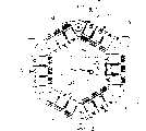
图15是表示电路板21的仰视图,如该图所示,2个电解电容器23分别是圆柱状的较大型零件。FIG. 15 is a bottom view showing the
这里,来自电源(未图示)的电力暂时供给电解电容器23并累积,再从该电解电容器23供给各开关元件24。从而,通过把连接器9U、9V及9W如前述那样配置,把电解电容器23设置成使它们的各个端子集中于电路板21的大致中央部,再把各开关元件24配置在电路板21的外周部,便可以使电解电容器23与各开关元件24间的配线长度尽量相等并缩短,这样,各开关元件24的配线电感(线性电感)均等,且可以分别降低前述各配线的电感。通过这样的构造,可以降低各开关元件24的浪涌电压。Here, electric power from a power source (not shown) is temporarily supplied to the
由于电容器的大容量化,如图所示,有把2个电解电容器23串联设置的,不过连接器9U、9V及9W必须设于不与电解电容器23重叠的位置。在这种场合,本实施例如前所述,把连接器9U、9V及9W设置成中心角θ1、θ2分别为150°的状态,从而既可以做到连接器9U、9V及9W不与电解电容器23重叠,又可使前述各配线的电感尽量均等。这样便可实现控制系统20的小型化,即实现无刷DC电动机1的小型化。Due to the increase in capacity of the capacitor, two
另外,前述的连接器9U、9V及9W的配置是本实施例中的较佳配置,而本发明中的连接器9U、9V及9W的配置并不只受此限。In addition, the aforementioned configurations of the connectors 9U, 9V and 9W are preferred configurations in this embodiment, but the configurations of the connectors 9U, 9V and 9W in the present invention are not limited thereto.
在这种场合,本发明最好是根据电路板21上设置的电解电容器23的数量和尺寸等各项条件而设置连接器9U、9V及9W,以使电解电容器23的端子位于电路板21的大致中央位置,进而使各开关元件24可设置在电路板21的外周部。In this case, the present invention is preferably provided with connectors 9U, 9V and 9W according to various conditions such as the quantity and size of the
譬如,当对电解电容器23的有关条件没有任何限制时,最好将前述中心角θ1、θ2分别设定为120°。For example, when there is no restriction on the conditions concerning the
另外,在该无刷DC电动机1上,是通过固定于连接器9U、9V及9W的后述导电性销子26而将各开关元件24与连接器9U、9V及9W进行电气接线,并固定电路板21的。In addition, in this brushless DC motor 1, each switching
关于这些连接器9U、9V及9W的构造,就典型的1相在后面详细叙述。The structures of these connectors 9U, 9V, and 9W will be described in detail later for a typical one phase.
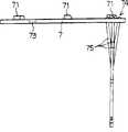
在本实施例中,如图1及图3所示,在树脂成形部4的顶端面,竖立着作为推压装置的6根轴向延伸的支柱43(一体成形)。In this embodiment, as shown in FIGS. 1 and 3 , on the front end surface of the resin molded
各支柱43分别与前述的各开关元件24对应配置。即,各支柱43在前述连接器9U、9V及9W的外周一侧、且在以旋转中心O为中心的同一圆的大致圆周上以等角度间隔配置。Each of the
另外,6根支柱43中的3根分别在其中途形成与电路板21卡合的阶梯(卡合部)44。在这种场合,有阶梯44的支柱43和无阶梯44的支柱43是交替配置的。该有阶梯44的支柱43相当于本发明中具有与第2电路板22卡合的卡合部的凸部。In addition, steps (engagement portions) 44 that engage with the
另外,前述的导电杆35在这些支柱43的外周一侧设置在以旋转中心O为中心的同一圆的大致圆周上。In addition, the above-mentioned
如图1所示,导电销(导电性的第1销子)25及导电销(导电性的第2销子)26分别通过旋入螺纹构件251、261而与导电杆35及连接器9的顶端连接、固定,电路板21则是通过分别旋入螺纹构件27、27而被固定在销子25、26的顶端。As shown in Figure 1, the conductive pin (the first pin of conductivity) 25 and the conductive pin (the second pin of conductivity) 26 are connected to the
在这种场合,如后所述,用于固定电路板21的前述导电杆35、销子25、26及连接器9等还可以作为把来自电源的电力供给控制系统20、进而供给电动机的路径发挥作用。因此,与那种要分别使用固定电路板21用的构件、把电源与控制系统20进行电气接线用的电缆、或把控制系统20与电动机进行电气接线用的电缆的场合相比,可减少零件数,而且可减少设置空间。从而,可实现无刷DC电动机1的小型化。而且组装容易。In this case, as will be described later, the aforementioned
另外,在电路板22上贯通着前述支柱43。该电路板22被作为加力装置的弹簧(螺旋弹簧)28向底端一侧加力,并通过与支柱43上形成的阶梯44卡合而与电路板21隔开一定距离地受到支撑。在这种场合,各弹簧28分别插入有阶梯44的各支柱43,且以受到压缩的状态设置于电路板21与电路板22之间,因此,使电路板22与支柱43卡合的状态得到保持。In addition, the above-mentioned
这样,本实施例的无刷DC电动机1是用弹簧28把电路板22固定的,故不会受电路板公差影响,能可靠地将电路板22固定,而且因为可在从顶端向底端的一个方向进行组装,故组装也很容易。而且与用衬垫或螺钉固定电路板的场合相比,还可减少空间,故有利于无刷DC电动机1的小型化。In this way, the brushless DC motor 1 of the present embodiment uses the
另外,如图15所示,在电路板21的底端一侧,在与有阶梯44的各支柱43对应的位置上,分别设有将弹簧28的端部定位的定位装置、即凸起45。各凸起45分别用焊锡一类的焊料构成。另外,凸起45设在电路板21上,电路板22上不设亦可。In addition, as shown in FIG. 15 , on the bottom end side of the
通过设置凸起45,可防止振动等导致的弹簧28错位(横向错位),稳定电路板22。By providing the protrusion 45, the displacement (lateral displacement) of the
另外,由于是用焊料形成凸起45的,故可以较简单地在电路板21上设置凸起45。In addition, since the bumps 45 are formed with solder, the bumps 45 can be provided on the
各开关元件24分别被对应的各支柱43经过电路板21而从底端一侧向顶端一侧、即向盖体5的内面一侧均等地推压,并经过前述的散热片29而与盖体5的顶端部内面接触(压接)。这样,由开关元件24产生的热量便经过散热片29而传递到盖体5的顶端部,并经过散热片51而向大气中散发。Each
在这种场合,各开关元件24被支柱43均等地推向盖体5的内面一侧,故可减少散热不均,同时可靠地散热。In this case, each switching
另外,与用螺钉把电路板或各开关元件固定在散热器上、并用电缆把电动机与电路板(开关元件)进行电气性接线的场合相比,本发明的无刷DC电动机1无需在盖体5上设置安装电路板用的螺纹孔,故可提高防水性。In addition, compared with the situation where the circuit board or each switching element is fixed on the radiator with screws, and the motor and the circuit board (switching element) are electrically connected with cables, the brushless DC motor 1 of the present invention does not need to be installed on the cover body. 5 is provided with threaded holes for installing circuit boards, so the water resistance can be improved.
还有,盖体5上不必设置安装电路板用的螺纹孔,且没有把电动机与电路板21、22进行电气性接线用的电缆,故组装容易。譬如可省略形成螺纹孔的工序,组装时不会发生配线的啮入、端子的接触等,不必为了避免妨碍其他构件而把又粗又硬的电缆(电力线)放入内部。In addition, there is no need to provide threaded holes for mounting circuit boards on the
盖构件6为筒状构件,既可防止水分或灰尘侵入电动机内部,同时又作为可旋转地支撑转子14底端一侧的支撑构件发挥作用。即,在盖构件6的顶端部,形成支撑轴承18用的轴承支撑部(轴承座)61,该轴承支撑部61内嵌入并固定着轴承18。The
在树脂成形部4的底端部埋有嵌入式螺母(埋设构件)63,通过把螺纹构件62旋入嵌入式螺母63而把盖构件6固定在树脂成形部4上。Insert nuts (embedded members) 63 are embedded in the bottom end of the resin molded
这种装在壳体2内的电动机具有定子(电枢)10和设于该定子10内侧的转子14。Such a motor housed in a
定子10固定设置在壳体2上,包括由冲压成所需形状的硅钢片层叠体构成的铁心11和在该铁心11上绕上线卷13后形成的线圈12。在线圈12内埋入可检测电动机温度的温度传感器(热敏电阻)8。The
铁心11的外径与筒体3的内径大致相等。在这种场合,铁心11以其外周面与筒体3内周面接触的状态插入筒体3,有利于提高散热性。The outer diameter of the
线圈12是由U相(第1相)、V相(第2相)及W相(第3相)构成的3相线圈。本说明书只就各相中典型的1相进行说明。The
这种定子10连同筒体3一起用构成树脂成形部4的树脂进行模压。传统技术在把定子插入铝等金属制的壳体内部进行组装时,如果壳体内径与定子外径的嵌合公差过小,则组装不便,而如果过大则空气会进入壳体与定子之间的间隙,会影响散热。而这一问题可通过本发明的树脂模压解决。也就是说,优先考虑组装性,增大壳体与定子之间的公差,同时用导热率高的树脂把其间的间隙填满,故散热性也可提高。This
另一方面,转子14由以下部分构成:由冲压成所需形状的硅钢片层叠体构成且具有多个磁极的轭铁16、设置(最好是埋入)在与轭铁16各磁极对应位置上的永久磁铁17、嵌入轭铁16中心部的旋转轴15。On the other hand, the rotor 14 is composed of the following parts: a
旋转轴15可旋转地受嵌入前述轴承支撑部61内的轴承18和嵌入树脂成形部4顶端形成的轴承支撑部(轴承座)41内的轴承19的支撑。在这种场合,旋转轴15比壳体2的底端、即盖构件6的底端更向底端一侧伸出。转子14的外周面(磁极的圆筒面)隔开规定的间隙而与定子10的内周面相面对。The
在把壳体2安装于摩托车本体后,旋转轴15的底端譬如与具有无级变速机构的传动机构(未图示)的输入轴连接。这样,电动机的旋转力便经过传动机构而传递到电动摩托车的驱动轮,使摩托车行驶。After the
如果采用磁性佳的磁铁作为永久磁铁17,即可实现无刷DC电动机1的小型化。譬如,可采用以稀土类元素、过渡金属和硼为基本成分的稀土类磁铁。If a magnet with good magnetic properties is used as the
如图1、图5及图16所示,在树脂成形部4的轴承支撑部41的底端面,设有环状电路板7,其上载有检测转子14位置用的的转子位置传感器(譬如霍尔元件)71。在该电路板7上形成供小螺钉76穿过的2个螺钉孔72以及电路板7定位用的缺口73。在螺钉孔72的处于底端面一侧的周围形成导电性材料构成的凸台(端子)721。As shown in Fig. 1, Fig. 5 and Fig. 16, on the bottom end surface of the
电路板7通过由小螺钉76和嵌入式螺母(埋设构件)77构成的固定装置(2处)而固定在树脂成形部4上。即,通过把穿过各螺钉孔72的小螺钉76旋入埋设在树脂成形部4的轴承支撑部41附近的嵌入式螺母77,把电路板7固定在树脂成形部4上。The
另外,在电路板7上设有端子部74,该端子部74具有分别与各转子位置传感器71及各凸台721接线的端子,端子部74的各个端子如图17所示,与向电路板背面一侧(顶端一侧)延长的导线75接线。该导线75插入在轴承19周围、即在树脂成形部4的轴承支撑部41附近形成的轴向贯通孔42内,并在树脂成形部4的顶端面露出。In addition, a
如图18所示,嵌入式螺母77内部形成阴螺纹771,其顶端部(与阴螺纹771上与螺纹孔开口772相反一侧的端部)形成细径部773。该细径部773如图19所示,用焊锡之类的焊料82焊接(锡焊)着温度传感器8的信号输出线81的端部。As shown in FIG. 18 , a female screw 771 is formed inside the embedded
细径部773具有直径缩小的缩径部,形成易于保持焊料82的形状,而且因为是细径,热容量小,容易达到焊料82的融点。因此,可以方便地以高接合强度进行这类焊接,而且不会浪费焊料。从而,当在后述的制造工序[6]中注入树脂时,可防止树脂的压力造成信号输出线81的端部从细径部773脱出而断线。The small-diameter portion 773 has a reduced-diameter portion, which is formed in a shape that is easy to hold the
另外,在嵌入式螺母77的底端外周部形成阶梯部(配合面)774。该阶梯部774在进行树脂模压时具有与型芯103嵌合的嵌合部作用,以把嵌入式螺母77牢固地固定在后述的金属模100内(尤其是防止树脂成形时的上浮)。另外,即使是对前述的导电杆35或嵌入式螺母63等其他埋设构件,出于同样的理由,最好是形成与阶梯部774同样的阶梯部或其他嵌合部。In addition, a stepped portion (fitting surface) 774 is formed on the outer peripheral portion of the bottom end of the embedded
另外,在嵌入式螺母77的外周面,以嵌入式螺母77埋入树脂成形部4内部的状态形成防止拔出或旋转用的滚花(凹凸)775。In addition, on the outer peripheral surface of the embedded
与温度传感器8检测的电动机温度对应的信号经过信号输出线81、嵌入式螺母77、小螺钉76、凸台721、电路板7上的规定配线、端子部74的规定端子及导线75而从树脂成形部4的顶端部向外取出。The signal corresponding to the temperature of the motor detected by the
另外,各转子位置传感器71与转子14的永久磁铁17的通过同步地输出检测信号,该信号经过电路板7上规定的配线、端子部74的规定端子及导线75而从树脂成形部4的顶端向外取出。In addition, each
于是,由于可利用电路板固定用的嵌入式螺母77及小螺钉76来取出温度传感器8的检测信号,故实现了零件的通用,有利于简化构造,同时不会影响后述分型面104的位置等,可以把配线向树脂成形部4的外部引出。Then, since the detection signal of the
向定子10的线圈12的通电经过埋设于树脂成形部4内轴承支撑部41附近的连接器(埋设构件)9进行。以下说明该连接器9的构造。Electricity is supplied to the
如图20及21所示,连接器(引出线连接器)9由第1夹持构件91和第2夹持构件92构成。第1夹持构件91上形成阴螺纹911。第2夹持构件92上形成底端部与前述阴螺纹911螺纹结合的阳螺纹921,其顶端部形成阴螺纹922。把前述螺纹构件261旋入阴螺纹922,连接销子26。As shown in FIGS. 20 and 21 , the connector (lead wire connector) 9 is composed of a first holding
在第1夹持构件91上与阴螺纹911相反一侧的端部形成槽912。该槽912具有与后述的销子112顶端的凸出部114嵌合的嵌合部的作用,在进行树脂模压时,可以防止树脂压力造成的连接器9移动、旋转。A
在第2夹持构件92的顶端外周部,形成阶梯部(嵌合面)93。该阶梯部93具有与可动销子108的底端嵌合的嵌合部的作用,在进行树脂模压时,可以把连接器9牢固地固定在后述的金属模100上(特别是可防止树脂成形时的上浮)。A stepped portion (fitting surface) 93 is formed on the distal end outer peripheral portion of the second holding
另外,在第1夹持构件91及第2夹持构件92的外周部形成滚花(凹凸)94,当连接器9埋设于树脂成形部4内时可防止其拔出或旋转。In addition, knurls (concavities and convexities) 94 are formed on the outer peripheral portions of the first holding
另一方面,在线卷13的端部安装着端子构件(压接端子)95。端子构件95由筒状压接部96、与该压接部96连成一体的环状平板部97构成。线卷13的端部被压接部96夹持并压接固定。平板部97相对压接部96的轴线大致弯折成90°。在平板部97的中央部形成供第2夹持构件92的阳螺纹921的一部分穿过的圆形开口98。On the other hand, a terminal member (crimp terminal) 95 is attached to an end portion of the
使第2夹持构件92的阳螺纹921的一部分穿过平板部97的开口98,把第2夹持构件92相对第1夹持构件91而向规定方向旋转,把阳螺纹921旋入第1夹持构件91的阴螺纹911内。这样,第1夹持构件91便与第2夹持构件92接近,在它们的夹持面913、923之间夹持并固定端子构件95的平板部97。A part of the
由于压接部96是沿轴向延伸的,故把平板部97相对压接部96的轴线大致弯折90°,可防止在后述的制造工序[7]中注入树脂时因树脂的压力导致端子构件95变形、破损,进而可防止线卷13的端部从压接部96脱出而断线。Since the crimping
在本实施例中,第1夹持构件91和第2夹持构件92分别用导电性不同的材料构成。即,第1夹持构件91用价格低廉的黄铜构成,第2夹持构件92用导电性高于黄铜的无氧铜(OFC)构成。向线圈12的通电是经过第2夹持构件92及端子构件95进行的,故第1夹持构件91用价格低廉的材料,而第2夹持构件92用导电性高的材料,既可抑制零件成本上升,同时又可得到导电性良好的连接器9。In this embodiment, the first clamping
另外,关于端子构件95,最好使用譬如无氧铜一类导电性高的材料。In addition, for the
由于使用上述连接器9,故不会影响后述分型面104的位置等,可以在树脂成形部4的顶端部确保向线圈12的电力供给路径。另外,连接器9配置在轴承支撑部41附近,其顶端高度与线圈12顶端部高度基本相等,故在半径方向和轴向不设凸出部,可以用较小空间埋设于树脂成形部4内。其结果是,有利于DC无刷电动机1的小型化。Since the
如前所述,在树脂成形部4的轴承支撑部41附近埋设有3个连接器9,且形成1个贯通孔42,而各连接器9及贯通孔42设置在从转子14的旋转中心起大致等距离的位置上(见图6)。而且最好连接器9的外径和贯通孔42的内径大致相同。这样,可以使树脂收缩导致的轴承支撑部41的轴承嵌入孔的变形均匀化,提高尺寸精度。As mentioned above, three
图22所示是把端子构件95的平板部97用销子112与可动销108夹持后进行模压的。即,使在销子112端面112a上形成的凸起部112b穿过端子构件95的开口98,与可动销108的嵌合部(未图示)嵌合,并在销子112的端面112a与可动销108的端面108a之间夹持端子构件95的平板部97。在这种场合,由于销子112与可动销108压接,故不必形成前例那样的阳螺纹921和阴螺纹911。As shown in FIG. 22, the
图23是连接器9的另一实施形态,该连接器9通过熔焊等把端子构件95的平板部97固定在第1夹持构件91的下端而连成一体。在这种场合,由于不必夹持端子构件95的平板部97,故可提高作业效率。FIG. 23 shows another embodiment of the
另外,来自电源(未图示)的电力经过导电杆35、销子25及螺纹构件27而向电路板21上的控制电路(包含反相电路)供给,进而经过螺纹构件27、销子26、连接器9及端子构件95而向线圈12的各相供给。这样,铁心11被励磁,在转子14上发生扭矩。在这种场合,向线圈12的通电基于转子位置传感器71的检测信号而受控制系统20控制。In addition, the power from the power supply (not shown) is supplied to the control circuit (including the inverter circuit) on the
以上所述的无刷DC电动机1是在肋31的底端部用譬如螺栓安装在小型摩托车本体上的。在这种场合,在小型摩托车本体和筒体3的底端面之间根据需要进行防水.防尘处理。关于该防水·防尘处理,譬如可以在其中安装液密性密封构件。作为这种密封构件,可以是橡胶一类弹性材料构成的环状构件、前述的液状填料,以及固化的粘接剂等。The brushless DC motor 1 described above is mounted to the scooter body at the bottom end of the
以下结合图24说明无刷DC电动机1的制造方法。Next, a method of manufacturing the brushless DC motor 1 will be described with reference to FIG. 24 .
首先,用金属模100制造壳体2的主要部分。金属模100主要由下模(第1金属模)101、经过分型面104而与该下模101接合的上模(第2金属模)102、处于下模101和上模102的内部并插入它们的大致中心部的型芯(第3金属模)103构成。型芯103的底端部嵌入并固定在下模101上。First, the main part of the
下模101上形成插入嵌入式螺母63的螺纹孔的嵌入式螺母固定用凸起105、及供导电杆35的底端嵌合的导电杆固定用嵌合凹部106。The lower mold 101 is formed with a protrusion 105 for fixing an embedded nut to be inserted into a threaded hole of the embedded
上模102上形成注入树脂的注入路径(注入口)107、供分别固定导电杆35及连接器9的可动销(固定构件)108贯通的贯通孔109、及在与下模101之间推压支撑筒体3的支撑部110。另外,通过充填在注入路径107内的树脂,形成前述的支柱43。Formed on the upper mold 102 is an injection path (injection port) 107 for injecting resin, a through-hole 109 through which a movable pin (fixing member) 108 for fixing the
在型芯(中央轴)103上形成分别供销子(固定构件)111、112插入的插入孔115、116。销子111、112的顶端从型芯103伸出,该伸出部113、114分别与嵌入式螺母77的阴螺纹771的螺纹孔及连接器9的槽912嵌合并将它们固定。Insertion holes 115 , 116 into which pins (fixing members) 111 , 112 are inserted are formed in core (central shaft) 103 , respectively. The top ends of the
销子111在对嵌入式螺母77定位的同时防止树脂从底端部侵入。销子112对连接器9进行定位。可动销108防止连接器9向上浮,并进行轴向定位,同时防止树脂从顶端部侵入。The pin 111 prevents resin from entering from the bottom end while positioning the embedded
另外,销子111、112在型芯103上设置在用树脂形成轴承支撑部41的那一部分周围。In addition, pins 111, 112 are provided on the core 103 around the portion where the
传统技术是把线卷13的端部和温度传感器8的信号输出线81等埋设在树脂成形部4内的零件的输入输出线以直线状态引出到树脂成形部4的外部。而且这些线要横穿分型面而向外部引出。即,要在分型面的局部制造槽,而且该槽在模压时不能让树脂流到外部,在该槽内配置上述输入输出线,并进行树脂模压。其结果,由于分型面必须与输入输出线的引出位置相适应,故金属模的分型面形状非常复杂。导致金属模的加工困难,而且在分离金属模时,输入输出线、特别是像信号输出线81那样的细线容易断线。In the conventional technique, the end of the
而如果像本发明那样利用销子111、112及可动销108将连接器9和嵌入式螺母77进行固定时,由于接触金属模的那部分为刚性高的金属,故分割金属模时不会发生断线。而且输入输出线不是横穿分型面104,故输入输出线的引出不会影响分型面104的位置,即,可以经过埋设的构件输入输出电气信号,从而,不必因为前述的理由而使分型形状复杂化。And if utilize pin 111,112 and
本实施例的无刷DC电动机1尤其可通过销子26而以最短距离把对位于树脂成形部4顶端部的电动机进行控制的控制系统20与连接器9进行接线,可以提高电动机的效率。进而,由于可以把连接器9和嵌入式螺母77可靠地埋设在由金属模决定的位置,故当在这些埋设部分组装销子26和电路板7等其他部分时可提高组装精度。In particular, the brushless DC motor 1 of this embodiment can connect the
另外,在型芯103的外周面形成对铁心11进行轴向定位用的阶梯状卡合部117。In addition, a stepped engaging portion 117 for positioning the
以下说明无刷DC电动机1的制造工序。The manufacturing process of the brushless DC motor 1 will be described below.
[1]把已将嵌入式螺母77与信号输出线81焊接后的温度传感器8插入线圈12的内部。用连接器9把线圈12各相的端子构件95夹持并作好电气性接线。[1] Insert the
[2]把嵌入式螺母63与下模101的凸起105嵌合配置。[2] Fitting the embedded
[3]把定子10嵌入,直至铁心11的底端内周部与型芯103的卡合部117卡合。把线圈12各相的连接器9与金属模的对应伸出部114嵌合固定,同时各嵌入式螺母77也与对应的伸出部113嵌合配置。[3] Insert the
[4]把筒体3嵌入定子10的外侧,直至其底端与下模101的分型面104卡合。这时,把导电杆35插入筒体3,并把其底端与下模101的嵌合凹部106嵌合配置。[4] Insert the
[5]把上模102对着下模101,使它们的分型面104之间紧密接合。这样,筒体3便被支撑部110和下模101的分型面104推压固定,由下模101、筒体3、上模102和型芯103构成型腔118。这时,安装在上模102上的各可动销108的底端与连接器9的顶端(阶梯部93)及导电杆35的顶端嵌合。这样,连接器9便被伸出部114和可动销108的底端推压固定,导电杆35被嵌合凹部106和可动销108的底端推压固定。[5] Put the upper mold 102 against the lower mold 101 so that their parting surfaces 104 are tightly bonded. In this way, the
[6]从上模102的注入路径107向型腔118内注入熔融树脂。在譬如注入聚酯树脂时,最好金属模温度为130℃~140℃,树脂温度也相同,注入压力为80~120kg/cm2。一旦经过规定时间后,注入的树脂固化,即形成前述的树脂成形体4。[6] The molten resin is injected into the cavity 118 from the injection path 107 of the upper mold 102 . For example, when injecting polyester resin, it is preferable that the mold temperature is 130°C to 140°C, the temperature of the resin is also the same, and the injection pressure is 80 to 120kg/cm2 . After a predetermined time has elapsed, the injected resin is cured to form the aforementioned resin molded
[7]把下模101和上模102分离,把筒体3、定子10及树脂成形体4的一体物从型芯103取出。[7] The lower mold 101 and the upper mold 102 are separated, and the integral body of the
[8]把轴承18的内圈嵌入转子14的旋转轴15的底端部,把轴承19的内圈嵌入旋转轴15的顶端部。[8] Fit the inner ring of the
[9]在树脂成形部4上轴承支撑部41附近,在露出开口772的各嵌入式螺母77的各个螺钉孔72内旋入小螺钉76,由此而把电路板7固定。[9] In the vicinity of the
[10]在树脂成形部4上轴承支撑部41附近,放入对轴承进行预负荷用的波形垫片,再把嵌入转子14的轴承19的外圈插入。接着,把盖构件6安装在树脂成形部4的底端,使轴承18插入盖构件6的轴承支撑部61,并通过把螺纹构件62旋入嵌入式螺母63而进行固定。[10] In the vicinity of the
[11]把销子25、26分别与露出在树脂成形部4顶端面的导电杆35及连接器9的顶端连接。[11] Connect the
[12]按照前述的配置预先准备好顶端一侧装有各开关元件24、底端一侧装有各电解电容器23的电路板21和装有控制系统20及其他构成零件的电路板22。并在电路板21和电路板22之间进行规定的配线。而且在各开关元件24的上侧面分别设置散热片29。[12] The
[13]在支栓43上插入前述电路板22,进而插入弹簧28,然后在销子25、26的顶端用螺纹构件27把电路板21固定。[13] Insert the above-mentioned
[14]以覆盖控制系统20的状态安装盖体5,通过旋紧螺栓52而把盖体5与筒体3连接固定。在筒体3与盖体5的分界部,根据需要进行前述的防水·防尘处理。[14] Install the
经过以上步骤,便完成了无刷DC电动机1的安装。如上所述,无刷DC电动机1只要在从顶端向底端的一个方向叠装零件便可完成组装。After the above steps, the installation of the brushless DC motor 1 is completed. As described above, the brushless DC motor 1 can be assembled by stacking components in one direction from the top end to the bottom end.
以上是结合图示的实施例说明本发明的无刷DC电动机,本发明的无刷DC电动机并不限于所述的实施例。The brushless DC motor of the present invention has been described above with reference to the illustrated embodiments, but the brushless DC motor of the present invention is not limited to the described embodiments.
而且本发明的电动机不限于在上述的电动小型摩托车和电动汽车使用,其用途多种多样。Moreover, the electric motor of the present invention is not limited to use in the above-mentioned electric scooters and electric vehicles, and its applications are various.
以上实施例的无刷DC电动机是把电动机以及对该电动机的驱动进行控制的控制系统装在壳体内,故组装容易,可靠性高。In the brushless DC motor of the above embodiments, the motor and the control system for controlling the driving of the motor are installed in the casing, so the assembly is easy and the reliability is high.
而且由于零件共用,可以简化构造,使无电刷DC电动机小型化,同时可降低成本。And because the parts are shared, the structure can be simplified, the brushless DC motor can be miniaturized, and the cost can be reduced at the same time.
特别是在壳体上覆盖控制系统的部分设有散热器时,电动机的散热路径与控制系统的散热路径采用共用构件,故可节省空间。Especially when a heat sink is provided on the part of the casing covering the control system, the heat dissipation path of the motor and the heat dissipation path of the control system use a common component, so space can be saved.
另外,当采用使来自电源的电力经过导电杆而向控制系统供给、来自控制系统的输出经过连接器而向线圈通电的构造时,对于该导电杆和连接器来说,通过导电销既可以向电路板通电,又可以进行固定,故可以减少零件数量,有利于无刷DC电动机的小型化。In addition, when a structure is adopted in which the power from the power supply is supplied to the control system through the conductive rod, and the output from the control system is energized to the coil through the connector, for the conductive rod and the connector, the conductive pin can be used to supply the control system. The circuit board can be energized and fixed, so the number of parts can be reduced, which is beneficial to the miniaturization of the brushless DC motor.
另外,当设定第1连接器和第2连接器之间对于圆心的中心角θ1为150±10°、第1连接器和前述第3连接器之间对于圆心的中心角θ2为150±10°时,以及控制系统的开关元件在电路板上呈环状配置时,可以在电路板上实现有利于控制系统小型化和集约化的零件配置,有利于无刷DC电动机的进一步小型化。In addition, when setting the central angle θ1 between the first connector and the second connector to the center of the circle as 150±10°, and the central angle θ2 between the first connector and the aforementioned third connector to the center of the circle is 150±10° °, and when the switching elements of the control system are arranged in a ring shape on the circuit board, it is possible to realize a component configuration on the circuit board that is conducive to the miniaturization and intensification of the control system, and is conducive to the further miniaturization of the brushless DC motor.
另外,由于在设有固定构件时,可将各开关元件全部设置在电路板上,而且在设有导电杆时可以省略电缆,故组装及安装更加简单。In addition, when the fixing member is provided, all the switching elements can be arranged on the circuit board, and when the conductive rod is provided, the cable can be omitted, so the assembly and installation are more simple.
而且在设有导电杆的场合,可以将导线等在壳体内外的露出部分限制在最小范围,从而可防止断线,提高可靠性。In addition, when the conductive rod is provided, the exposed parts of the wires inside and outside the casing can be limited to a minimum range, thereby preventing disconnection and improving reliability.
还有,由于可以在从顶端向底端的一个方向进行无刷DC电动机的组装,故有利于实施组装自动化。Also, since the brushless DC motor can be assembled in one direction from the top to the bottom, it is advantageous to automate assembly.
工业上利用的可能性Possibility of industrial use
本发明是把电动机和对该电动机的驱动进行控制的控制系统装于壳体内,组装及安装容易、可靠性高,故适于作为电动小型摩托车或电动汽车等车辆的驱动源使用。In the present invention, the electric motor and the control system for controlling the driving of the electric motor are installed in the casing, which is easy to assemble and install and has high reliability, so it is suitable for use as a driving source for vehicles such as electric small motorcycles or electric automobiles.
权利要求书claims
按照条约第19条的修改Amendments pursuant to
1.(补正)一种电动机,把具有定子和转子的驱动系统及控制该驱动系统并具有电路板的控制系统安装于壳体内,1. (Replenishment) A motor in which a driving system having a stator and a rotor and a control system controlling the driving system and having a circuit board are installed in a housing,
其特征在于,在所述壳体内还设有供向所述控制系统输入的电源电流流通的第1导电销、及供从所述控制系统向线圈的各相输出的电流流通的第2导电销,并用螺钉把所述电路板固定在所述第1和第2导电销上。It is characterized in that a first conductive pin through which the power supply current input to the control system flows, and a second conductive pin through which the current output from the control system to each phase of the coil flows are also provided in the housing. , and fix the circuit board on the first and second conductive pins with screws.
2.根据权利要求1所述的电动机,其特征在于,所述控制系统具有相面对设置的第1电路板及第2电路板,所述第1电路板通过所述第1及第2导电销而支撑在所述壳体上,还设有对所述第2电路板向脱离所述第1电路板的方向加力的加力装置。2. The motor according to claim 1, wherein the control system has a first circuit board and a second circuit board facing each other, and the first circuit board is electrically conductive through the first and second circuit boards. A pin is supported on the housing, and an urging device for urging the second circuit board in a direction away from the first circuit board is provided.
3.根据权利要求2所述的电动机,其特征在于,所述加力装置是弹簧,具有将该弹簧的端部定位的定位构件。3. The electric motor according to
4.根据权利要求3所述的电动机,其特征在于,所述定位构件是用钎焊料在所述第1电路板及(或)第2电路板上形成的凸起。4. The motor according to
5.根据权利要求3或4所述的电动机,其特征在于,所述壳体设有凸部,该凸部具有与所述第2电路板卡合的卡合部,所述弹簧是插入所述凸部且以压缩状态设置在所述第1电路板和所述第2电路板之间的螺旋弹簧,所述第2电路板受所述螺旋弹簧加力,从而保持所述第2电路板与所述卡合部卡合的状态。5. The motor according to
6.(补正)根据权利要求1所述的电动机,其特征在于,所述控制系统具有多个开关元件,通过沿所述电动机的旋转轴方向延伸且分别与所述各开关元件对应竖立的多个支柱构成的推压装置使各开关元件经过散热片而与金属制散热器的内面接触。6. (Remedy) The electric motor according to claim 1, wherein the control system has a plurality of switching elements, and the plurality of switching elements extending in the direction of the rotation axis of the motor and standing upright corresponding to the respective switching elements The pressing device composed of two pillars makes each switching element contact with the inner surface of the metal heat sink through the heat sink.
7.(删除)7. (deleted)
8.(补正)根据权利要求6所述的电动机,其特征在于,所述多个支柱用树脂模压一体成形。8. (Amendment) The electric motor according to
9.(补正)根据权利要求1所述的电动机,其特征在于,所述壳体是把所述定子和内包该定子的金属制筒体用热膨胀系数小于所述筒体材料的树脂进行模压后形成。9. (Amendment) The electric motor according to claim 1, wherein the casing is formed by molding the stator and the metal cylinder enclosing the stator with a resin having a coefficient of thermal expansion smaller than that of the material of the cylinder. form.
10.根据权利要求9所述的电动机,其特征在于,在所述筒体上形成把所述壳体安装于其他部位用的安装部、以及把所述金属制散热器安装于所述壳体上用的安装部,且使所述散热器与所述筒体接触并固定。10. The electric motor according to
11.根据权利要求1所述的电动机,其特征在于,所述壳体具有用与该壳体电气绝缘的固定装置固定的一对导电杆,所述转子具有在所述壳体的一端伸出的旋转轴,在所述各导电杆的与所述旋转轴的伸出端相同一侧的端部形成与电源接线用的端子,同时在与所述旋转轴的伸出端相反一侧的端部形成与所述第1导电销接线用的端子。11. The electric motor according to claim 1, wherein the housing has a pair of conductive rods fixed by a fixing device electrically insulated from the housing, and the rotor has a motor protruding from one end of the housing. The rotating shaft of each conductive rod is formed at the end of the same side as the protruding end of the rotating shaft to form a terminal for power connection, and at the same time, at the end of the opposite side of the protruding end of the rotating shaft The part forms a terminal for connecting with the first conductive pin.
12.根据权利要求11所述的电动机,其特征在于,所述电气绝缘的固定装置用树脂模压形成。12. The electric motor according to
13.根据权利要求1所述的电动机,其特征在于,所述定子具有铁心及在该铁心上绕有线卷的线圈,所述线卷的端部与连接器接线,该连接器用电气绝缘的固定装置固定在壳体上,在所述连接器的与所述旋转轴的伸出端相反一侧的端部形成与所述第2导电销接线用的端子。13. The electric motor according to claim 1, wherein the stator has an iron core and a coil wound with a wire coil on the iron core, the end of the wire coil is connected to a connector, and the connector is fixed with an electrically insulating The device is fixed on the housing, and a terminal for connecting with the second conductive pin is formed at the end of the connector opposite to the protruding end of the rotating shaft.
14.根据权利要求13所述的电动机,其特征在于,所述线圈由第1相、第2相及第3相组成,所述连接器由与所述第1相接线的第1连接器、与所述第2相接线的第2连接器、与所述第3相接线的第3连接器构成,并且设置在同一圆的大致圆周上,所述第1连接器与所述第2连接器之间针对所述圆心形成的中心角θ1为150±10°,所述第1连接器与所述第3连接器之间针对所述圆心形成的中心角θ2为150±10°。14. The motor according to
15.根据权利要求13所述的电动机,其特征在于,所述连接器通过所述电气绝缘的固定装置而固定在壳体的转子用轴承支撑部附近。15. The electric motor according to
16.根据权利要求15所述的电动机,其特征在于,所述电气绝缘的固定装置及所述轴承支撑部用树脂模压成形。16. The electric motor according to
17.根据权利要求16所述的电动机,其特征在于,在所述轴承支撑部附近设有贯通孔供检测所述转子位置的信号的信号输出线插入,所述贯通孔在进行树脂模压时通过金属模成形,且所述贯通孔的内径与所述连接器的外径大致相同。17. The motor according to
18.根据权利要求13所述的电动机,其特征在于,所述连接器由与所述线圈接线的端子构件、形成阴螺纹的第1夹持构件、形成与所述阴螺纹螺纹结合的阳螺纹的第2夹持构件构成,所述端子构件具有平板部,而且通过把所述阳螺纹旋入所述阴螺纹而用所述第1夹持构件和所述第2夹持构件夹持所述平板部。18. The electric motor according to
19.根据权利要求18所述的电动机,其特征在于,所述第1夹持构件和所述第2夹持构件用导电性不同的材料构成。19. The electric motor according to
20.根据权利要求1所述的电动机,其特征在于,所述壳体具有用树脂模压的定子、装有检测所述转子位置的检测传感器的传感器电路板、埋设于所述树脂内的温度传感器、把所述传感器电路板固定在所述壳体上的固定装置,且所述固定装置由埋设于所述树脂内的嵌入式螺母及与该嵌入式螺母螺纹结合的小螺钉构成,所述温度传感器的信号输出线与所述嵌入式螺母接线,经过所述嵌入式螺母及所述小螺钉而与所述传感器电路板上的端子通电。20. The motor according to claim 1, wherein the housing has a stator molded with resin, a sensor circuit board equipped with a detection sensor for detecting the position of the rotor, and a temperature sensor embedded in the resin. . A fixing device for fixing the sensor circuit board on the housing, and the fixing device is composed of an embedded nut embedded in the resin and a small screw threaded with the embedded nut. The temperature The signal output line of the sensor is wired with the embedded nut, and is electrically connected to the terminal on the sensor circuit board through the embedded nut and the small screw.
21.根据权利要求20所述的电动机,其特征在于,所述嵌入式螺母埋设于可旋转地支撑所述转子的轴承的轴承支撑部附近。21. The electric motor according to
22.根据权利要求21所述的电动机,其特征在于,所述嵌入式螺母在与其螺钉孔的开口相反一侧的端部设有细径部,在该细径部锡焊所述信号输出线。22. The motor according to
23.(补正)一种电动机,把具有定子和转子的驱动系统及控制该驱动系统并具有电路板的控制系统安装于壳体内,且在所述电路板上将多个开关元件排列成环状,其特征在于,所述开关元件具有向一端伸出的端子群,该端子群以交替朝向所述电路板内周一侧和外周一侧的状态排列。23. (Replenishment) A motor in which a driving system having a stator and a rotor and a control system controlling the driving system and having a circuit board are installed in a casing, and a plurality of switching elements are arranged in a ring on the circuit board , characterized in that the switching element has a terminal group protruding toward one end, and the terminal group is arranged in a state alternately facing the inner peripheral side and the outer peripheral side of the circuit board.
24.(删除)24. (deleted)
25.(删除)25. (deleted)
26.(补正)根据权利要求23所述的电动机,其特征在于,所述各开关元件通过固定构件而设置在所述电路板上,所述固定构件整体大致呈正六角形的环状,在六角形的各边上形成决定所述各开关元件的固定位置用的阶梯部。26. (Amendment) The motor according to
27.(删除)27. (deleted)
28.(删除)28. (deleted)
29.(删除)29. (deleted)
30.(删除)30. (deleted)
31.(删除)31. (deleted)
32.(删除)32. (deleted)
Claims (32)
Applications Claiming Priority (6)
| Application Number | Priority Date | Filing Date | Title |
|---|---|---|---|
| JP50633/96 | 1996-03-07 | ||
| JP5063396 | 1996-03-07 | ||
| JP50633/1996 | 1996-03-07 | ||
| JP73725/1996 | 1996-03-28 | ||
| JP7372596 | 1996-03-28 | ||
| JP73725/96 | 1996-03-28 |
Publications (2)
| Publication Number | Publication Date |
|---|---|
| CN1190500Atrue CN1190500A (en) | 1998-08-12 |
| CN1067495C CN1067495C (en) | 2001-06-20 |
Family
ID=26391100
Family Applications (1)
| Application Number | Title | Priority Date | Filing Date |
|---|---|---|---|
| CN97190480AExpired - Fee RelatedCN1067495C (en) | 1996-03-07 | 1997-03-04 | Motor and process for producing the same |
Country Status (5)
| Country | Link |
|---|---|
| US (1) | US6081056A (en) |
| JP (1) | JP3612715B2 (en) |
| CN (1) | CN1067495C (en) |
| TW (1) | TW356617B (en) |
| WO (1) | WO1997033359A1 (en) |
Cited By (18)
| Publication number | Priority date | Publication date | Assignee | Title |
|---|---|---|---|---|
| CN101873016A (en)* | 2009-04-27 | 2010-10-27 | 三洋电机株式会社 | Motor and motor vehicle |
| CN101902098A (en)* | 2009-05-27 | 2010-12-01 | 山洋电气株式会社 | The radiator structure of electric device |
| CN102005889A (en)* | 2010-12-02 | 2011-04-06 | 大连依德斯科技有限公司 | Electrically driven equipment with control function of brushless direct current motor |
| CN102017374A (en)* | 2008-06-13 | 2011-04-13 | 三菱电机株式会社 | Motor positioning structure |
| CN102159835A (en)* | 2008-09-19 | 2011-08-17 | 格伦德福斯管理联合股份公司 | Pump aggregate |
| US8294328B2 (en) | 2008-08-22 | 2012-10-23 | Johnson Electric S.A. | Brush gear of a motor |
| CN102780320A (en)* | 2011-05-11 | 2012-11-14 | 株式会社电装 | Drive unit |
| CN103379809A (en)* | 2012-04-25 | 2013-10-30 | 株式会社捷太格特 | Control device and motor unit including control device |
| CN103516068A (en)* | 2012-06-14 | 2014-01-15 | 舍弗勒技术股份两合公司 | Electrical machine and corresponding hydrostatic actuator having an electrical machine designed as an electric motor |
| CN103987611A (en)* | 2012-01-25 | 2014-08-13 | 三菱电机株式会社 | Electric Power Steering |
| CN105743287A (en)* | 2014-12-25 | 2016-07-06 | 株式会社捷太格特 | Motor unit |
| CN106849523A (en)* | 2015-11-04 | 2017-06-13 | 株式会社电装 | Electronic equipment |
| CN110915111A (en)* | 2017-07-18 | 2020-03-24 | 三菱电机株式会社 | Electric motor and ventilation fan |
| CN111033974A (en)* | 2017-09-29 | 2020-04-17 | 日本电产伺服有限公司 | Motor with a stator having a stator core |
| CN113169472A (en)* | 2018-12-27 | 2021-07-23 | 日立安斯泰莫株式会社 | Electronic Controls and Electric Power Steering |
| CN113824246A (en)* | 2020-06-19 | 2021-12-21 | 施耐宝公司 | Brushless DC motor end cover |
| CN114183338A (en)* | 2020-09-15 | 2022-03-15 | 浙江三花汽车零部件有限公司 | Electronic oil pump |
| CN114552907A (en)* | 2022-03-09 | 2022-05-27 | 深圳市力辉电机有限公司 | Processing device of micro motor |
Families Citing this family (101)
| Publication number | Priority date | Publication date | Assignee | Title |
|---|---|---|---|---|
| CN1574558A (en)* | 1997-07-19 | 2005-02-02 | 东京研发股份有限公司 | Motor |
| WO1999054986A1 (en)* | 1998-04-23 | 1999-10-28 | Citizen Watch Co., Ltd. | Rotor of small-sized motor |
| US6949849B1 (en)* | 1998-06-30 | 2005-09-27 | General Electric Company | Motor endshield assembly for an electronically commutated motor |
| WO2001006617A1 (en)* | 1999-07-15 | 2001-01-25 | Moriyama Manufacturing Co., Ltd. | Rotating electric machine |
| EP1081827B1 (en)* | 1999-09-01 | 2003-01-22 | Ramachandran Ramarathnam | A portable electric tool |
| JP2001163287A (en)* | 1999-09-30 | 2001-06-19 | Honda Motor Co Ltd | Electric auxiliary unit of electric auxiliary vehicle |
| JP2001298903A (en)* | 2000-04-10 | 2001-10-26 | Moric Co Ltd | Brushless dc motor |
| DE10033862C2 (en)* | 2000-07-12 | 2002-07-11 | Buhler Motor Gmbh | Electric motor, especially a brushless pump motor |
| DE10119404A1 (en) | 2001-04-20 | 2002-10-24 | Bosch Gmbh Robert | Electronically commutated dc motor e.g. for cooling water pump in vehicle, has grid stamping for providing all connections to electronic system |
| US6380648B1 (en)* | 2001-06-11 | 2002-04-30 | Chun-Pu Hsu | Wheel drum structure of inner stator portion with inbuilt switches |
| DE10137371A1 (en) | 2001-07-31 | 2003-02-13 | Bosch Gmbh Robert | Method for producing a multi-functional combined support part for an electrical externally mounted device/drive mechanism e.g. in motor vehicle, involves forming a bottom area on the combined support part. |
| JP2003052160A (en)* | 2001-08-06 | 2003-02-21 | Tokyo R & D Co Ltd | Motor |
| GB0130149D0 (en)* | 2001-12-18 | 2002-02-06 | Johnson Electric Sa | Electric motor |
| EP1322021B1 (en)* | 2001-12-23 | 2005-08-31 | Grundfos A/S | Stator for an electric motor |
| JP3593102B2 (en)* | 2002-01-08 | 2004-11-24 | 三菱電機株式会社 | Electric power steering device |
| US20030164649A1 (en)* | 2002-03-04 | 2003-09-04 | Cym Graphics Inc. | Integral motor having a multidimensional shaft for rotary scanners |
| US6897584B2 (en)* | 2002-04-25 | 2005-05-24 | Honeywell International Inc. | High power terminal block assembly for generators and method of assembling and installing the same |
| DE10331877A1 (en)* | 2002-07-15 | 2004-06-24 | Kabushiki Kaisha Toyota Jidoshokki, Kariya | electric compressor |
| JP4265902B2 (en)* | 2002-11-05 | 2009-05-20 | 株式会社ミツバ | Motor unit |
| JP4064806B2 (en)* | 2002-12-19 | 2008-03-19 | ヤマハモーターエレクトロニクス株式会社 | Structure of synchronous motor for power assist |
| US6982532B2 (en)* | 2003-12-08 | 2006-01-03 | A. O. Smith Corporation | Electric machine |
| DE502004004636D1 (en)* | 2004-04-02 | 2007-09-27 | Grundfos As | pump unit |
| US8387258B2 (en)* | 2004-05-07 | 2013-03-05 | Teco-Westinghouse Motor Company | Insulated bearing assemblies |
| JP3900172B2 (en)* | 2004-06-25 | 2007-04-04 | 松下電器産業株式会社 | Electric motor |
| US7687945B2 (en)* | 2004-09-25 | 2010-03-30 | Bluwav Systems LLC. | Method and system for cooling a motor or motor enclosure |
| WO2006100839A1 (en)* | 2005-03-23 | 2006-09-28 | Toyota Jidosha Kabushiki Kaisha | Temperature detector and fixing material transmission suppressing structure |
| CN100418287C (en)* | 2005-06-10 | 2008-09-10 | 富准精密工业(深圳)有限公司 | motor stator |
| ATE483114T1 (en)* | 2005-08-24 | 2010-10-15 | Mecos Traxler Ag | MAGNETIC BEARING DEVICE WITH IMPROVED HOUSING FEED-THROUGH IN VACUUM |
| DE102006008416A1 (en)* | 2006-02-21 | 2007-08-23 | Zf Friedrichshafen Ag | Electric drive for an adjustable stabilizer |
| US20080030088A1 (en)* | 2006-07-18 | 2008-02-07 | Daniel Gizaw | Compact integrated brushless permanent-magnet motor & drive |
| CN200990577Y (en)* | 2006-08-28 | 2007-12-12 | 中山大洋电机股份有限公司 | A Controller Structure of Brushless DC Motor |
| US8008805B2 (en)* | 2006-12-07 | 2011-08-30 | Nissan Motor Co., Ltd. | Power conversion apparatus and motor drive system |
| US20080197731A1 (en)* | 2007-02-15 | 2008-08-21 | Nidec Corporation | Brushless motor and pump mounted with brushless motor |
| JP5235312B2 (en)* | 2007-02-22 | 2013-07-10 | サンデン株式会社 | Manufacturing method of inverter-integrated electric compressor |
| JP4986657B2 (en)* | 2007-03-09 | 2012-07-25 | パナソニック株式会社 | Brushless motor |
| JPWO2008136061A1 (en)* | 2007-04-19 | 2010-07-29 | 三菱電機株式会社 | Electric motor, pump, and electric motor manufacturing method |
| CN101102068B (en)* | 2007-08-08 | 2010-12-29 | 江门市汉宇电器有限公司 | Permanent magnetic synchronization motor for water discharge pump |
| JP5285258B2 (en)* | 2007-09-28 | 2013-09-11 | 三菱重工業株式会社 | Electric compressor |
| ITBO20070791A1 (en)* | 2007-11-30 | 2009-06-01 | Spal Automotive Srl | ROTARY ELECTRIC MACHINE AND ASSEMBLY METHOD OF THE SAME. |
| DE112008003499B4 (en)* | 2007-12-27 | 2017-11-16 | Mitsubishi Electric Corp. | Bearing device for a rotary motor |
| CA2716877A1 (en)* | 2008-03-17 | 2009-09-24 | F. Hoffmann-La Roche Ag | Lxr ligand binding domain (lxr lbd) crystals |
| JP5062484B2 (en)* | 2008-04-07 | 2012-10-31 | アイシン・エィ・ダブリュ株式会社 | Drive device |
| JP4582182B2 (en)* | 2008-04-08 | 2010-11-17 | 三菱電機株式会社 | Electric power steering device |
| JP4673911B2 (en)* | 2008-08-12 | 2011-04-20 | トヨタ自動車株式会社 | Rotating electric machine and rotating electric machine cooling system |
| US10038349B2 (en)* | 2008-08-15 | 2018-07-31 | Millennial Research Corporation | Multi-phase modular coil element for electric motor and generator |
| JP5359220B2 (en)* | 2008-11-21 | 2013-12-04 | 日産自動車株式会社 | Motor structure and motor manufacturing method |
| US8227948B1 (en) | 2009-01-09 | 2012-07-24 | Hydro-Gear Limited Partnership | Electric motor |
| CN101826766B (en)* | 2009-03-05 | 2012-11-28 | 建准电机工业股份有限公司 | Inner rotor motor |
| MX2011010884A (en)* | 2009-04-16 | 2012-01-19 | Zhongshan Broad Ocean Motor | Motor. |
| US8643231B2 (en)* | 2009-05-18 | 2014-02-04 | Moog Inc. | Water-resistant electric motor |
| DE102009022675A1 (en)* | 2009-05-26 | 2010-12-16 | Horiba Europe Gmbh | Test bench with temperature-controlled cooling fan |
| DE102010017522A1 (en)* | 2009-06-24 | 2011-02-03 | ASMO Co., Ltd., Kosai-city | Drive device and semiconductor module |
| JP4811749B2 (en)* | 2009-06-24 | 2011-11-09 | 株式会社デンソー | Drive device |
| JP5435286B2 (en) | 2009-06-24 | 2014-03-05 | 株式会社デンソー | Drive device |
| JP5327646B2 (en)* | 2009-06-24 | 2013-10-30 | 株式会社デンソー | Motor with built-in electronic circuit |
| JP5435284B2 (en) | 2009-06-24 | 2014-03-05 | 株式会社デンソー | Drive device |
| JP5516066B2 (en)* | 2009-06-24 | 2014-06-11 | 株式会社デンソー | Drive device |
| JP5435285B2 (en)* | 2009-06-24 | 2014-03-05 | 株式会社デンソー | Drive device |
| US8159095B2 (en)* | 2009-09-14 | 2012-04-17 | Hiwin Mikrosystem Corp. | Hiding structure for positioning signal conversion mechanism of a torque motor |
| EP2567451A2 (en)* | 2010-05-04 | 2013-03-13 | Remy Technologies, LLC | Electric machine component temperature monitoring |
| JP2011240772A (en)* | 2010-05-17 | 2011-12-01 | Ntn Corp | In-wheel motor drive device |
| JP5177711B2 (en)* | 2010-05-21 | 2013-04-10 | 株式会社デンソー | Electric device |
| JP5692588B2 (en)* | 2010-12-28 | 2015-04-01 | 株式会社デンソー | Drive device |
| JP5692575B2 (en) | 2010-12-28 | 2015-04-01 | 株式会社デンソー | Drive device |
| EP2533405B1 (en)* | 2011-06-10 | 2013-12-25 | ebm-papst Mulfingen GmbH & Co. KG | Stator for an EC motor and EC motor with such a stator |
| TWI437799B (en)* | 2011-07-21 | 2014-05-11 | Sunonwealth Electr Mach Ind Co | Glue-coated stator |
| WO2013046412A1 (en)* | 2011-09-29 | 2013-04-04 | 株式会社安川電機 | Motor drive device and vehicle |
| KR101346477B1 (en)* | 2011-09-30 | 2014-01-10 | 미쓰비시덴키 가부시키가이샤 | motor |
| JP5518108B2 (en)* | 2012-01-25 | 2014-06-11 | 三菱電機株式会社 | Electric power steering device |
| JP5518107B2 (en)* | 2012-01-25 | 2014-06-11 | 三菱電機株式会社 | Electric power steering device |
| JP2013201878A (en)* | 2012-02-24 | 2013-10-03 | Nissan Motor Co Ltd | Mechano-electric motor and assembly method of mechano-electric motor |
| JP5660400B2 (en)* | 2012-08-03 | 2015-01-28 | 株式会社デンソー | Rotating electric machine and electric power steering apparatus using the same |
| US10155278B2 (en)* | 2012-08-31 | 2018-12-18 | Illinois Tool Works Inc. | Wire feeder assembly with motor mount |
| CN202840836U (en)* | 2012-08-31 | 2013-03-27 | 中山大洋电机股份有限公司 | A DC brushless motor structure |
| US10135321B2 (en) | 2012-09-14 | 2018-11-20 | Rockwell Automation Technologies, Inc. | Heatsink design with thermal insulator to reduce encoder temperature |
| US9543811B2 (en)* | 2012-09-14 | 2017-01-10 | Rockwell Automation Technologies, Inc. | Heatsink design with thermal insulator to reduce encoder temperature |
| ITBO20120682A1 (en)* | 2012-12-18 | 2014-06-19 | Spal Automotive Srl | ELECTRIC MACHINE |
| US9071093B2 (en)* | 2012-12-23 | 2015-06-30 | Asia Vital Components (China) Co., Ltd. | Base structure for cooling fan |
| JP5725055B2 (en) | 2013-02-12 | 2015-05-27 | 株式会社デンソー | Electronic control unit |
| ITBO20130063A1 (en)* | 2013-02-14 | 2014-08-15 | Spal Automotive Srl | ELECTRIC MACHINE. |
| US9948156B2 (en) | 2013-03-15 | 2018-04-17 | Moog Inc. | Lawn mower motor and drive |
| JP6052244B2 (en)* | 2014-06-30 | 2016-12-27 | 日本精工株式会社 | Motor, electric power steering apparatus equipped with the motor, and vehicle |
| JP2016019362A (en)* | 2014-07-08 | 2016-02-01 | 三菱電機株式会社 | Brushless motor |
| JP6325945B2 (en)* | 2014-08-27 | 2018-05-16 | タイコエレクトロニクスジャパン合同会社 | Female connector used for motor |
| DE102015213043A1 (en)* | 2015-07-13 | 2017-01-19 | Robert Bosch Gmbh | Electric machine tool with an electronically commutated drive motor |
| DK3345285T3 (en)* | 2015-09-03 | 2021-05-10 | Fluid Handling Llc | Submersible pump housing for improving the serviceability of submersible pumps |
| FR3042077B1 (en)* | 2015-10-05 | 2019-05-31 | Safran Landing Systems | ELECTRIC MOTOR. |
| JP6639962B2 (en)* | 2016-03-09 | 2020-02-05 | 日立オートモティブシステムズ株式会社 | Electric drive device and electric power steering device |
| JP6666788B2 (en)* | 2016-05-12 | 2020-03-18 | 株式会社ミクニ | Drive unit and pump unit |
| WO2018023153A1 (en)* | 2016-08-05 | 2018-02-08 | Enertion Boards Pty Ltd | A hanger and wheel assembly for a motorised skateboard |
| KR102182396B1 (en)* | 2016-09-28 | 2020-11-24 | 미쓰비시덴키 가부시키가이샤 | Electric motor, blower, air conditioner and manufacturing method of electric motor |
| WO2018062004A1 (en)* | 2016-09-30 | 2018-04-05 | 日本電産株式会社 | Motor control device, motor, and electric power steering apparatus |
| AT519371B1 (en)* | 2016-12-20 | 2018-06-15 | Melecs Ews Gmbh | Housing for an electrical machine with a cooling device |
| JP7031441B2 (en)* | 2017-09-28 | 2022-03-08 | 日本電産株式会社 | motor |
| US10879749B2 (en) | 2017-11-22 | 2020-12-29 | American Axle & Manufacturing, Inc. | Electric motor and stator cooling apparatus |
| US20210052125A1 (en)* | 2018-03-23 | 2021-02-25 | Mitsubishi Electric Corporation | Electric blower, vacuum cleaner, and hand dryer |
| TWI683508B (en)* | 2018-11-22 | 2020-01-21 | 財團法人工業技術研究院 | Heat dissipation assembly and motor inverter thereof |
| US11444514B2 (en)* | 2019-10-24 | 2022-09-13 | Te Connectivity India Private Limited Et Al. | Sensor module for mounting in a motor |
| DE112021001825A5 (en) | 2020-03-25 | 2023-01-05 | Magna powertrain gmbh & co kg | Resolver for an electrical machine |
| WO2021199236A1 (en) | 2020-03-31 | 2021-10-07 | 平田機工株式会社 | Dynamo-electric machine |
| JP7478010B2 (en) | 2020-03-31 | 2024-05-02 | 平田機工株式会社 | Rotating Electric Machine |
Family Cites Families (45)
| Publication number | Priority date | Publication date | Assignee | Title |
|---|---|---|---|---|
| CA1103298A (en)* | 1977-02-25 | 1981-06-16 | Masami Uchiyama | Electric motor with discrete rotor position and speed sensors |
| JPS5755274U (en)* | 1980-09-18 | 1982-03-31 | ||
| JPS57119642A (en)* | 1981-01-17 | 1982-07-26 | Mitsubishi Electric Corp | Submerged motor |
| JPS58121178U (en)* | 1982-02-10 | 1983-08-18 | 松下電器産業株式会社 | Submersible commutatorless motor |
| JPS58124490U (en)* | 1982-02-17 | 1983-08-24 | 住江織物株式会社 | Durable needle punch carpet |
| JPS60119761A (en)* | 1983-12-01 | 1985-06-27 | Pioneer Electronic Corp | Mounting method of electronic parts |
| JPS60171072U (en)* | 1984-04-18 | 1985-11-13 | 株式会社東芝 | brushless motor |
| DE3439665A1 (en)* | 1984-10-30 | 1986-05-07 | Ebm Elektrobau Mulfingen Gmbh & Co, 7119 Mulfingen | COLLECTORLESS DC MOTOR |
| DE3505092A1 (en)* | 1985-02-14 | 1986-08-21 | Papst-Motoren GmbH & Co KG, 7742 St Georgen | LACQUERED WIRE CONTACT CONNECTION TO PCB |
| US4633110A (en)* | 1985-03-20 | 1986-12-30 | Rotron, Inc. | Motor with stator on printed circuit assembly |
| JPS62115758A (en)* | 1985-11-14 | 1987-05-27 | Sony Corp | Method and apparatus for mounting electronic component parts |
| US4668898A (en)* | 1986-04-21 | 1987-05-26 | General Electric Company | Electronically commutated motor |
| JPH0632762Y2 (en)* | 1987-11-12 | 1994-08-24 | ダイキン工業株式会社 | Fan device |
| JPH0646214Y2 (en)* | 1988-04-21 | 1994-11-24 | ダイキン工業株式会社 | Fan device |
| JPH0237578U (en)* | 1988-08-30 | 1990-03-13 | ||
| JPH0279761A (en)* | 1988-09-14 | 1990-03-20 | Matsushita Electric Works Ltd | Dc brushless motor |
| JP2844610B2 (en)* | 1988-09-14 | 1999-01-06 | 松下電器産業株式会社 | Mold motor |
| DE3842588A1 (en)* | 1988-12-17 | 1990-06-21 | Mulfingen Elektrobau Ebm | COLLECTORLESS OUTDOOR ROTOR MOTOR WITH SEMICONDUCTOR COOLING ARRANGEMENT |
| JPH0389838A (en)* | 1989-06-08 | 1991-04-15 | Daikin Ind Ltd | Motor |
| JPH0398451A (en)* | 1989-09-11 | 1991-04-24 | Matsushita Electric Ind Co Ltd | brushless electric motor |
| JPH0644131Y2 (en)* | 1990-02-19 | 1994-11-14 | 株式会社広杉計器 | Substrate spacer |
| JPH0515101A (en)* | 1991-06-28 | 1993-01-22 | Asmo Co Ltd | Resin-molded type rotating electric machine |
| JPH0515050A (en)* | 1991-07-01 | 1993-01-22 | Mitsubishi Electric Corp | Power transistor failure detection device |
| DE4122529B4 (en)* | 1991-07-08 | 2006-04-20 | Robert Bosch Gmbh | Electronically commutated drive motor |
| DE4122653C2 (en)* | 1991-07-09 | 1996-04-11 | Daimler Benz Ag | Controllable semiconductor switching device with integrated current limitation and overtemperature shutdown |
| JPH05268755A (en)* | 1992-03-17 | 1993-10-15 | Matsushita Electric Ind Co Ltd | Brushless motor stator and manufacturing method thereof |
| JPH05292703A (en)* | 1992-04-09 | 1993-11-05 | Toyota Motor Corp | Motor for electric vehicle |
| JPH0698518A (en)* | 1992-09-17 | 1994-04-08 | Hitachi Ltd | DC brushless motor speed controller |
| JPH0677468U (en)* | 1993-03-31 | 1994-10-28 | 株式会社高岳製作所 | Motor |
| US5691584A (en)* | 1993-09-09 | 1997-11-25 | Honda Giken Kogyo Kabushiki Kaisha | Wheel motor for vehicles |
| JP3264573B2 (en)* | 1994-01-14 | 2002-03-11 | 株式会社三協精機製作所 | Small motor |
| JP3028905B2 (en)* | 1994-01-31 | 2000-04-04 | アイシン精機株式会社 | Rear wheel steering actuator |
| JP3271416B2 (en)* | 1994-02-18 | 2002-04-02 | 株式会社デンソー | POWER CONVERTER AND ELECTRIC VEHICLE DRIVE USING THE SAME |
| JP3552266B2 (en)* | 1994-03-31 | 2004-08-11 | 松下電器産業株式会社 | Mold motor mold |
| JPH07298543A (en)* | 1994-04-21 | 1995-11-10 | Mitsubishi Electric Corp | Molded motor and manufacturing method thereof |
| US5610458A (en)* | 1994-05-11 | 1997-03-11 | Emerson Electric Co. | Electrical connection of printed circuit board to line leads on brushless permanent magnet refrigeration motors |
| JP3195163B2 (en)* | 1994-06-10 | 2001-08-06 | 澤藤電機株式会社 | Alternator |
| JP3472624B2 (en)* | 1994-06-17 | 2003-12-02 | カヤバ工業株式会社 | Drive circuit for electric power steering device |
| JP3421142B2 (en)* | 1994-08-26 | 2003-06-30 | 株式会社エクォス・リサーチ | Vehicle mounted motor drive |
| JPH08149743A (en)* | 1994-11-25 | 1996-06-07 | Hitachi Ltd | Connection terminals for electrical equipment |
| US5663604A (en)* | 1994-12-28 | 1997-09-02 | Nidec Corporation | Brushless motor |
| JPH09182399A (en)* | 1995-12-22 | 1997-07-11 | Sony Corp | Motor and rotary magnetic head device |
| US5705868A (en)* | 1996-04-25 | 1998-01-06 | Seagate Technology, Inc. | Spindle motor connector having supported electrical leads |
| US5895994A (en)* | 1997-01-30 | 1999-04-20 | General Electric Company | Dynamoelectric machine |
| JPH10234158A (en)* | 1997-02-19 | 1998-09-02 | Tokyo R & D:Kk | Electric motor |
- 1997
- 1997-03-04WOPCT/JP1997/000661patent/WO1997033359A1/enactiveApplication Filing
- 1997-03-04JPJP53166197Apatent/JP3612715B2/ennot_activeExpired - Fee Related
- 1997-03-04CNCN97190480Apatent/CN1067495C/ennot_activeExpired - Fee Related
- 1997-03-04USUS09/101,268patent/US6081056A/ennot_activeExpired - Lifetime
- 1997-03-07TWTW086102792Apatent/TW356617B/ennot_activeIP Right Cessation
Cited By (30)
| Publication number | Priority date | Publication date | Assignee | Title |
|---|---|---|---|---|
| CN102017374A (en)* | 2008-06-13 | 2011-04-13 | 三菱电机株式会社 | Motor positioning structure |
| CN102017374B (en)* | 2008-06-13 | 2015-07-01 | 三菱电机株式会社 | Motor positioning structure |
| US8294328B2 (en) | 2008-08-22 | 2012-10-23 | Johnson Electric S.A. | Brush gear of a motor |
| CN101656387B (en)* | 2008-08-22 | 2013-02-13 | 德昌电机(深圳)有限公司 | Connection structure for carbon brush |
| CN102159835A (en)* | 2008-09-19 | 2011-08-17 | 格伦德福斯管理联合股份公司 | Pump aggregate |
| CN102159835B (en)* | 2008-09-19 | 2015-11-25 | 格伦德福斯管理联合股份公司 | Pump assembly |
| CN101873016A (en)* | 2009-04-27 | 2010-10-27 | 三洋电机株式会社 | Motor and motor vehicle |
| CN101902098B (en)* | 2009-05-27 | 2014-05-07 | 山洋电气株式会社 | Heat radiation structure of electric apparatus |
| CN101902098A (en)* | 2009-05-27 | 2010-12-01 | 山洋电气株式会社 | The radiator structure of electric device |
| CN102005889A (en)* | 2010-12-02 | 2011-04-06 | 大连依德斯科技有限公司 | Electrically driven equipment with control function of brushless direct current motor |
| CN102005889B (en)* | 2010-12-02 | 2013-03-27 | 大连依德斯科技有限公司 | Electrically driven equipment with control function of brushless direct current motor |
| CN102780320B (en)* | 2011-05-11 | 2015-09-09 | 株式会社电装 | Driver element |
| CN102780320A (en)* | 2011-05-11 | 2012-11-14 | 株式会社电装 | Drive unit |
| CN103987611A (en)* | 2012-01-25 | 2014-08-13 | 三菱电机株式会社 | Electric Power Steering |
| US9586615B2 (en) | 2012-01-25 | 2017-03-07 | Mitsubishi Electric Corporation | Electric power steering apparatus |
| CN103987611B (en)* | 2012-01-25 | 2017-03-08 | 三菱电机株式会社 | Driven steering device |
| CN103379809A (en)* | 2012-04-25 | 2013-10-30 | 株式会社捷太格特 | Control device and motor unit including control device |
| CN103516068B (en)* | 2012-06-14 | 2017-12-08 | 舍弗勒技术股份两合公司 | Electrical machine and corresponding hydrostatic actuator having an electrical machine designed as an electric motor |
| CN103516068A (en)* | 2012-06-14 | 2014-01-15 | 舍弗勒技术股份两合公司 | Electrical machine and corresponding hydrostatic actuator having an electrical machine designed as an electric motor |
| CN105743287A (en)* | 2014-12-25 | 2016-07-06 | 株式会社捷太格特 | Motor unit |
| CN106849523A (en)* | 2015-11-04 | 2017-06-13 | 株式会社电装 | Electronic equipment |
| CN106849523B (en)* | 2015-11-04 | 2019-06-21 | 株式会社电装 | Electronic equipment |
| CN110915111A (en)* | 2017-07-18 | 2020-03-24 | 三菱电机株式会社 | Electric motor and ventilation fan |
| CN111033974A (en)* | 2017-09-29 | 2020-04-17 | 日本电产伺服有限公司 | Motor with a stator having a stator core |
| CN111033974B (en)* | 2017-09-29 | 2022-05-17 | 日本电产伺服有限公司 | Motor |
| CN113169472A (en)* | 2018-12-27 | 2021-07-23 | 日立安斯泰莫株式会社 | Electronic Controls and Electric Power Steering |
| US11767053B2 (en) | 2018-12-27 | 2023-09-26 | Hitachi Astemo, Ltd. | Electronic control device and electric power steering device |
| CN113824246A (en)* | 2020-06-19 | 2021-12-21 | 施耐宝公司 | Brushless DC motor end cover |
| CN114183338A (en)* | 2020-09-15 | 2022-03-15 | 浙江三花汽车零部件有限公司 | Electronic oil pump |
| CN114552907A (en)* | 2022-03-09 | 2022-05-27 | 深圳市力辉电机有限公司 | Processing device of micro motor |
Also Published As
| Publication number | Publication date |
|---|---|
| CN1067495C (en) | 2001-06-20 |
| JP3612715B2 (en) | 2005-01-19 |
| US6081056A (en) | 2000-06-27 |
| TW356617B (en) | 1999-04-21 |
| WO1997033359A1 (en) | 1997-09-12 |
Similar Documents
| Publication | Publication Date | Title |
|---|---|---|
| CN1067495C (en) | Motor and process for producing the same | |
| CN1069791C (en) | Motor casing and method for manufacturing the same | |
| CN100347857C (en) | Power semiconductor device | |
| CN1279683C (en) | Capacitor device in AC generator and mfg. method thereof | |
| CN1897441A (en) | Capacitor mounting type inverter unit | |
| JP5649727B2 (en) | Drive unit-integrated rotating electrical machine | |
| JP6432235B2 (en) | Electric pump | |
| JP4120876B2 (en) | Semiconductor device | |
| JP5609289B2 (en) | Inverter integrated motor | |
| CN1673642A (en) | Electric heater | |
| CN1808851A (en) | Motor for electric power steering and method for manufacturing the same | |
| CN1139309A (en) | Vehicle-mounted dlternator | |
| CN105830314A (en) | Mechatronic driving device and manufacturing method thereof | |
| CN1105638A (en) | electric car | |
| CN1790649A (en) | Electronic circuit device and manufacturing method | |
| CN1866584A (en) | Capacitor device | |
| CN1797902A (en) | Electric power steering system, and motor and inverter used in same | |
| CN1403823A (en) | Wheel speed sensor, manufacturing method thereof, terminal, and method of welding terminal and wire | |
| CN1383167A (en) | Capacitor modular, and semiconductor device using same | |
| CN1799140A (en) | Switchgear, generator-motor equipment using switchgear, drive system including generator-motor equipment, and computer-readable recording medium having recorded thereon a program for instructing a computer to perform control of the generator-motor equipment | |
| CN113924718A (en) | Rotating electrical machine and method of manufacturing the same | |
| CN1620745A (en) | motor | |
| CN1073753C (en) | Plug-in conductor and method for manufacturing electric brush support | |
| CN1898112A (en) | Electronic control units for motor vehicle braking systems | |
| CN1428806A (en) | Thermal protector |
Legal Events
| Date | Code | Title | Description |
|---|---|---|---|
| C06 | Publication | ||
| PB01 | Publication | ||
| C10 | Entry into substantive examination | ||
| SE01 | Entry into force of request for substantive examination | ||
| C14 | Grant of patent or utility model | ||
| GR01 | Patent grant | ||
| REG | Reference to a national code | Ref country code:HK Ref legal event code:GR Ref document number:1055607 Country of ref document:HK | |
| CF01 | Termination of patent right due to non-payment of annual fee | Granted publication date:20010620 Termination date:20150304 | |
| EXPY | Termination of patent right or utility model |