CN1188995A - Antenna device and transmitting and receiving device using the antenna device - Google Patents
Antenna device and transmitting and receiving device using the antenna deviceDownload PDFInfo
- Publication number
- CN1188995A CN1188995ACN98103945ACN98103945ACN1188995ACN 1188995 ACN1188995 ACN 1188995ACN 98103945 ACN98103945 ACN 98103945ACN 98103945 ACN98103945 ACN 98103945ACN 1188995 ACN1188995 ACN 1188995A
- Authority
- CN
- China
- Prior art keywords
- dielectric
- lens
- antenna assembly
- main radiator
- transmitting
- Prior art date
- Legal status (The legal status is an assumption and is not a legal conclusion. Google has not performed a legal analysis and makes no representation as to the accuracy of the status listed.)
- Granted
Links
- 230000005855radiationEffects0.000claimsabstractdescription36
- 230000008859changeEffects0.000claimsabstractdescription14
- 230000008878couplingEffects0.000claimsdescription8
- 238000010168coupling processMethods0.000claimsdescription8
- 238000005859coupling reactionMethods0.000claimsdescription8
- 238000005259measurementMethods0.000description6
- 239000004698PolyethyleneSubstances0.000description4
- 238000010586diagramMethods0.000description4
- 230000005540biological transmissionEffects0.000description3
- 238000004364calculation methodMethods0.000description3
- 238000006073displacement reactionMethods0.000description3
- 230000005684electric fieldEffects0.000description3
- 238000000034methodMethods0.000description3
- 230000005284excitationEffects0.000description2
- -1polyethylenePolymers0.000description2
- 229920000573polyethylenePolymers0.000description2
- 239000000758substrateSubstances0.000description2
- 238000013459approachMethods0.000description1
- 230000007246mechanismEffects0.000description1
- 238000012986modificationMethods0.000description1
- 230000004048modificationEffects0.000description1
- 230000010355oscillationEffects0.000description1
- 238000012545processingMethods0.000description1
- 230000001902propagating effectEffects0.000description1
Images


Classifications
- H—ELECTRICITY
- H01—ELECTRIC ELEMENTS
- H01Q—ANTENNAS, i.e. RADIO AERIALS
- H01Q19/00—Combinations of primary active antenna elements and units with secondary devices, e.g. with quasi-optical devices, for giving the antenna a desired directional characteristic
- H01Q19/06—Combinations of primary active antenna elements and units with secondary devices, e.g. with quasi-optical devices, for giving the antenna a desired directional characteristic using refracting or diffracting devices, e.g. lens
- H01Q19/062—Combinations of primary active antenna elements and units with secondary devices, e.g. with quasi-optical devices, for giving the antenna a desired directional characteristic using refracting or diffracting devices, e.g. lens for focusing
- G—PHYSICS
- G01—MEASURING; TESTING
- G01S—RADIO DIRECTION-FINDING; RADIO NAVIGATION; DETERMINING DISTANCE OR VELOCITY BY USE OF RADIO WAVES; LOCATING OR PRESENCE-DETECTING BY USE OF THE REFLECTION OR RERADIATION OF RADIO WAVES; ANALOGOUS ARRANGEMENTS USING OTHER WAVES
- G01S13/00—Systems using the reflection or reradiation of radio waves, e.g. radar systems; Analogous systems using reflection or reradiation of waves whose nature or wavelength is irrelevant or unspecified
- G01S13/88—Radar or analogous systems specially adapted for specific applications
- G01S13/93—Radar or analogous systems specially adapted for specific applications for anti-collision purposes
- G01S13/931—Radar or analogous systems specially adapted for specific applications for anti-collision purposes of land vehicles
- G—PHYSICS
- G01—MEASURING; TESTING
- G01S—RADIO DIRECTION-FINDING; RADIO NAVIGATION; DETERMINING DISTANCE OR VELOCITY BY USE OF RADIO WAVES; LOCATING OR PRESENCE-DETECTING BY USE OF THE REFLECTION OR RERADIATION OF RADIO WAVES; ANALOGOUS ARRANGEMENTS USING OTHER WAVES
- G01S7/00—Details of systems according to groups G01S13/00, G01S15/00, G01S17/00
- G01S7/02—Details of systems according to groups G01S13/00, G01S15/00, G01S17/00 of systems according to group G01S13/00
- G01S7/03—Details of HF subsystems specially adapted therefor, e.g. common to transmitter and receiver
- G01S7/032—Constructional details for solid-state radar subsystems
- H—ELECTRICITY
- H01—ELECTRIC ELEMENTS
- H01Q—ANTENNAS, i.e. RADIO AERIALS
- H01Q19/00—Combinations of primary active antenna elements and units with secondary devices, e.g. with quasi-optical devices, for giving the antenna a desired directional characteristic
- H01Q19/06—Combinations of primary active antenna elements and units with secondary devices, e.g. with quasi-optical devices, for giving the antenna a desired directional characteristic using refracting or diffracting devices, e.g. lens
- H—ELECTRICITY
- H01—ELECTRIC ELEMENTS
- H01Q—ANTENNAS, i.e. RADIO AERIALS
- H01Q3/00—Arrangements for changing or varying the orientation or the shape of the directional pattern of the waves radiated from an antenna or antenna system
- H01Q3/12—Arrangements for changing or varying the orientation or the shape of the directional pattern of the waves radiated from an antenna or antenna system using mechanical relative movement between primary active elements and secondary devices of antennas or antenna systems
- H01Q3/14—Arrangements for changing or varying the orientation or the shape of the directional pattern of the waves radiated from an antenna or antenna system using mechanical relative movement between primary active elements and secondary devices of antennas or antenna systems for varying the relative position of primary active element and a refracting or diffracting device
- G—PHYSICS
- G01—MEASURING; TESTING
- G01S—RADIO DIRECTION-FINDING; RADIO NAVIGATION; DETERMINING DISTANCE OR VELOCITY BY USE OF RADIO WAVES; LOCATING OR PRESENCE-DETECTING BY USE OF THE REFLECTION OR RERADIATION OF RADIO WAVES; ANALOGOUS ARRANGEMENTS USING OTHER WAVES
- G01S13/00—Systems using the reflection or reradiation of radio waves, e.g. radar systems; Analogous systems using reflection or reradiation of waves whose nature or wavelength is irrelevant or unspecified
- G01S13/02—Systems using reflection of radio waves, e.g. primary radar systems; Analogous systems
- G01S13/06—Systems determining position data of a target
- G01S13/08—Systems for measuring distance only
- G01S13/32—Systems for measuring distance only using transmission of continuous waves, whether amplitude-, frequency-, or phase-modulated, or unmodulated
- G01S13/34—Systems for measuring distance only using transmission of continuous waves, whether amplitude-, frequency-, or phase-modulated, or unmodulated using transmission of continuous, frequency-modulated waves while heterodyning the received signal, or a signal derived therefrom, with a locally-generated signal related to the contemporaneously transmitted signal
- G—PHYSICS
- G01—MEASURING; TESTING
- G01S—RADIO DIRECTION-FINDING; RADIO NAVIGATION; DETERMINING DISTANCE OR VELOCITY BY USE OF RADIO WAVES; LOCATING OR PRESENCE-DETECTING BY USE OF THE REFLECTION OR RERADIATION OF RADIO WAVES; ANALOGOUS ARRANGEMENTS USING OTHER WAVES
- G01S13/00—Systems using the reflection or reradiation of radio waves, e.g. radar systems; Analogous systems using reflection or reradiation of waves whose nature or wavelength is irrelevant or unspecified
- G01S13/02—Systems using reflection of radio waves, e.g. primary radar systems; Analogous systems
- G01S13/06—Systems determining position data of a target
- G01S13/42—Simultaneous measurement of distance and other co-ordinates
- G—PHYSICS
- G01—MEASURING; TESTING
- G01S—RADIO DIRECTION-FINDING; RADIO NAVIGATION; DETERMINING DISTANCE OR VELOCITY BY USE OF RADIO WAVES; LOCATING OR PRESENCE-DETECTING BY USE OF THE REFLECTION OR RERADIATION OF RADIO WAVES; ANALOGOUS ARRANGEMENTS USING OTHER WAVES
- G01S13/00—Systems using the reflection or reradiation of radio waves, e.g. radar systems; Analogous systems using reflection or reradiation of waves whose nature or wavelength is irrelevant or unspecified
- G01S13/88—Radar or analogous systems specially adapted for specific applications
- G01S13/93—Radar or analogous systems specially adapted for specific applications for anti-collision purposes
- G01S13/931—Radar or analogous systems specially adapted for specific applications for anti-collision purposes of land vehicles
- G01S2013/932—Radar or analogous systems specially adapted for specific applications for anti-collision purposes of land vehicles using own vehicle data, e.g. ground speed, steering wheel direction
- G—PHYSICS
- G01—MEASURING; TESTING
- G01S—RADIO DIRECTION-FINDING; RADIO NAVIGATION; DETERMINING DISTANCE OR VELOCITY BY USE OF RADIO WAVES; LOCATING OR PRESENCE-DETECTING BY USE OF THE REFLECTION OR RERADIATION OF RADIO WAVES; ANALOGOUS ARRANGEMENTS USING OTHER WAVES
- G01S13/00—Systems using the reflection or reradiation of radio waves, e.g. radar systems; Analogous systems using reflection or reradiation of waves whose nature or wavelength is irrelevant or unspecified
- G01S13/88—Radar or analogous systems specially adapted for specific applications
- G01S13/93—Radar or analogous systems specially adapted for specific applications for anti-collision purposes
- G01S13/931—Radar or analogous systems specially adapted for specific applications for anti-collision purposes of land vehicles
- G01S2013/9327—Sensor installation details
- G01S2013/93271—Sensor installation details in the front of the vehicles
Landscapes
- Engineering & Computer Science (AREA)
- Radar, Positioning & Navigation (AREA)
- Remote Sensing (AREA)
- Physics & Mathematics (AREA)
- Computer Networks & Wireless Communication (AREA)
- General Physics & Mathematics (AREA)
- Electromagnetism (AREA)
- Aerials With Secondary Devices (AREA)
- Radar Systems Or Details Thereof (AREA)
- Variable-Direction Aerials And Aerial Arrays (AREA)
- Details Of Aerials (AREA)
Abstract
Translated fromChineseDescription
Translated fromChinese本发明涉及天线装置,尤其涉及发射和接收毫米波段电磁波的雷达或类似设备所用的一种天线装置,以及采用该天线装置的发射和接收装置。The present invention relates to an antenna device, in particular to an antenna device used in a radar or similar equipment for transmitting and receiving electromagnetic waves in the millimeter wave band, and a transmitting and receiving device using the antenna device.
安装于机动车辆的毫米波雷达应用于支持安全驱动汽车的系统内。毫米波雷达用以测量与另一辆汽车并排行驶的汽车与其它汽车之间的距离,或汽车周围障碍物与汽车之间的距离。根据测量数据,执行车速控制和刹车,这样可以防止碰撞另一辆汽车或障碍物。Millimeter-wave radars installed in motor vehicles are used in systems that support safe driving of vehicles. Millimeter wave radar is used to measure the distance between a car driving alongside another car and other cars, or the distance between obstacles around the car and the car. Based on the measurement data, vehicle speed control and braking are performed, which prevents a collision with another car or an obstacle.
通常,采用毫米波雷达的发射和接收组件结合了毫米波振荡器、循环器、方向耦合器、混频器、天线等等。Typically, transmit and receive components using mmWave radar combine mmWave oscillators, circulators, directional couplers, mixers, antennas, and more.
图21所示右侧车辆通过FM-CW(调频-连续波)方法,由雷达向左侧的汽车发射毫米波,并接收从左侧汽车反射的毫米波。通过已知的计算方法可以计算右侧与左侧汽车之间的距离,以及两辆汽车之间的相对速度。The car on the right shown in Fig. 21 uses the FM-CW (Frequency Modulation-Continuous Wave) method. The radar transmits millimeter waves to the car on the left and receives the millimeter waves reflected from the car on the left. The distance between the right and left vehicles and the relative speed between the two vehicles can be calculated by known calculation methods.
通过图22所示的信号处理部分完成计算。计算结果送到控制部分。例如当右侧汽车的驾驶速度等于或高于预定值,以及右侧和左侧汽车之间的距离等于或低于预定值时,控制部分使警告装置工作。或者,在给定的条件下,控制部分可以操纵右侧汽车的刹车装置。The calculation is done by the signal processing section shown in Fig. 22. The calculation result is sent to the control part. For example, the control section operates the warning device when the driving speed of the right car is equal to or higher than a predetermined value and the distance between the right and left cars is equal to or lower than a predetermined value. Alternatively, under given conditions, the control section can operate the brakes of the right-hand car.
由于常用毫米波雷达所用天线的方向性是固定的,故产生了以下所述的各种不便。Since the directivity of an antenna used in a conventional millimeter-wave radar is fixed, various inconveniences described below arise.
如图18所示,当各辆汽车行驶在两条平行的公路上时,从汽车Cm的雷达发射的毫米波可以到达前方的汽车Ca和Cb。这是因为不能通过调节改变天线的方向性,从而使毫米波仅仅发射到汽车Cm正在行驶的公路内的汽车上。As shown in FIG. 18, when the cars are running on two parallel roads, millimeter waves emitted from the radar of the car Cm can reach the cars Ca and Cb ahead. This is because the directivity of the antenna cannot be changed by adjustment, so that the millimeter waves are only emitted to the cars on the road where the car Cm is driving.
到达各辆汽车的毫米波由汽车Cm反射和接收。由于汽车Cb和Cm行驶在各条公路上,即使汽车Cb和Cm相互得很靠近,汽车Cm也不必执行特定的安全控制。The millimeter wave reaching each car is reflected and received by the car Cm. Since the cars Cb and Cm are traveling on various roads, even if the cars Cb and Cm are in close proximity to each other, the car Cm does not have to execute specific safety control.
然而,汽车Cm无法识别接收波究竟是从汽车Ca还是Cb反射的。因此,当汽车Cb与Cm之间的车距小于容许距离时,仍由汽车Cm执行安全控制。However, the car Cm cannot identify whether the received wave is reflected from the car Ca or Cb. Therefore, when the distance between the cars Cb and Cm is smaller than the allowable distance, the safety control is still performed by the car Cm.
此外,当天线的方向性为固定时,将产生诸如以下所述的不便。Furthermore, when the directivity of the antenna is fixed, inconveniences such as described below will occur.
如图19所示,驶近弯道人口的汽车Cm发射一个毫米波B1;然而,该毫米波无法到达驶近弯道出口的汽车Ca。As shown in FIG. 19, a car Cm approaching the entrance of a curve emits a millimeter wave B1; however, this millimeter wave cannot reach a car Ca approaching the exit of the curve.
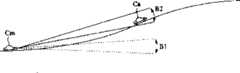
而且,如图20所示,在公路有斜坡和倾斜的情况下,在斜坡前行驶的汽车Cm发射毫米波B1,但无法检测正行驶在斜坡上的汽车Ca。Also, as shown in FIG. 20, when the road has a slope and slope, the car Cm running before the slope emits the millimeter wave B1, but the car Ca running on the slope cannot be detected.
因此,为了解决上述问题,可以采用以下方法改变辐射波束的方向。Therefore, in order to solve the above problems, the following method can be used to change the direction of the radiation beam.
例如,图18中,分别发射辐射波束B1、B2和B3,以对每一方向进行测量。通过比较这些结果,可以个别检测汽车Ca和Cb。For example, in Figure 18, radiation beams B1, B2 and B3 are emitted separately to make measurements in each direction. By comparing these results, auto Ca and Cb can be detected individually.
在图19所示例子中,根据舵轮的操作识别汽车Cm前方弯道的出现,毫米波B1切换到毫米波B2。还有一种方法是分析摄像机输入的图像检测弯道。而且,图20所示例子中,通过分析摄像机输入的图像检测到斜坡,将毫米波B1切换到毫米波B2。In the example shown in FIG. 19, the occurrence of a curve ahead of the car Cm is recognized based on the operation of the steering wheel, and the millimeter wave B1 is switched to the millimeter wave B2. Another approach is to analyze the image input from the camera to detect curves. Also, in the example shown in FIG. 20, the millimeter wave B1 is switched to the millimeter wave B2 by detecting a slope by analyzing the image input from the camera.
常规雷达系统中,通过电机或类似部件旋转内装天线的发射和接收装置的罩壳,改变电磁波发射波束的辐射方向。由于罩壳包括了除天线以外的其它部件,故很难减小罩壳旋转机构的尺寸。因此,很难以高速旋转罩壳,以高速扫描辐射波束。In a conventional radar system, a motor or similar components is used to rotate the casing of the transmitting and receiving device with the built-in antenna to change the radiation direction of the electromagnetic wave transmitting beam. Since the housing includes components other than the antenna, it is difficult to reduce the size of the housing rotating mechanism. Therefore, it is difficult to rotate the enclosure at high speed and scan the radiation beam at high speed.
本发明的目的在于提供一种天线装置,以及采用该天线装置的发射和接收装置,它具有小尺寸并能以高速切换天线的方向性。SUMMARY OF THE INVENTION An object of the present invention is to provide an antenna device, and a transmitting and receiving device using the antenna device, which are small in size and capable of switching the directivity of the antenna at high speed.
根据本发明第一方面的天线装置,它包括用以辐射雷达波的主辐射元件,以及用以聚焦雷达波的介质透镜,其中,主辐射元件可在透镜的聚焦平面内移动。相对主辐射元件透镜的位置变化,使主天线装置发射的雷达波束的方向性改变。由于主辐射元件相对较轻,故元件驱动装置的规模可以较小。此外,由于主辐射元件的惯性较小,故可以以高速移动主辐射元件,使雷达波束的高速扫描成为可能。The antenna device according to the first aspect of the present invention comprises a main radiating element for radiating radar waves, and a dielectric lens for focusing radar waves, wherein the main radiating element can move within the focal plane of the lens. The change of the position of the lens relative to the main radiating element changes the directivity of the radar beam emitted by the main antenna device. Since the main radiating element is relatively light, the scale of the element driving device can be small. In addition, since the inertia of the main radiating element is small, the main radiating element can be moved at high speed, making high-speed scanning of the radar beam possible.
根据本发明另一方面的天线装置,介质透镜中心轴相对主辐射元件辐射平面的方向是可变的。According to the antenna device in another aspect of the present invention, the direction of the central axis of the dielectric lens relative to the radiation plane of the main radiating element is variable.
根据本发明另一方面的天线装置,为了移动主辐射器在介质透镜聚焦平面内的位置,如权利要求3所述,主辐射器包括用作输入/输出部分的第一介质线,耦合到第一介质线的介质谐振器,以及发射出电磁波或使之沿轴向辐射的开口部分,第二介质透镜靠近第一介质线设置以形成方向耦合器,在第一和第二介质线耦合部分内改变介质透镜与主辐射器之间的相对位置关系。由于输入和输出至/来自上述主辐射器之信号的可移动部分,是由主辐射器一侧上的介质线和另一介质线形成的方向耦合器形成的,故维持该耦合关系时,可以改变主辐射器与介质透镜之间的相对位置。According to the antenna device of another aspect of the present invention, in order to move the position of the main radiator in the focal plane of the dielectric lens, as described in
在方向耦合器中,如权利要求4所述,如耦合量大致为0分贝,可以尽可能大地抑制方向耦合器的传输损耗,并不减小天线的效率。In the directional coupler, as described in
此外,如权利要求5所述,本发明的天线装置中,发射部分、接收部分和分离发射信号和接收信号的环形器均连接到第二介质线,故天线装置可用于发射和接收。结果,由第一介质线和耦合到第一介质线的介质谐振器,以及耦合到第一介质线的第二介质线所组成的主辐射器可以用于发射和接收,由此防止因利用方向耦合器形成可移动部分而导致大尺寸。Furthermore, as described in
再者,如权利要求6所述,本发明在如权利要求1至5任一所述的天线装置内设置一个驱动部分,用以改变介质透镜与主辐射器之间的相对位置关系,由此形成发射和接收装置。结果,可以获得能够定向扫描天线的小型发射和接收装置。Furthermore, as described in
从以下结合附图所作的描述中,本发明的上述和进一步的目的、各个方面以及新颖的特征将变得更加明白。The above and further objects, various aspects and novel features of the present invention will become more apparent from the following description taken in conjunction with the accompanying drawings.
图1A、1B、1C、1D、1E和1F表示根据本发明第一个实施例的天线装置的介质透镜与主辐射器之间的关系,以及与辐射波束倾斜角的关系;1A, 1B, 1C, 1D, 1E and 1F represent the relationship between the dielectric lens and the main radiator of the antenna device according to the first embodiment of the present invention, and the relationship with the radiation beam tilt angle;
图2A、2B和2C表示根据本发明第一个实施例的天线装置的介质透镜与主辐射器之间的另一关系,以及与辐射波束倾斜角的关系;2A, 2B and 2C represent another relationship between the dielectric lens and the main radiator of the antenna device according to the first embodiment of the present invention, and the relationship with the radiation beam inclination angle;
图3A和3B表示辐射波束倾斜角相对主辐射器与介质透镜偏移量的测量结果;3A and 3B represent the measurement results of the tilt angle of the radiation beam relative to the offset between the main radiator and the medium lens;
图4A和4B表示当介质透镜角度相对主辐射器改变时,对辐射波束倾斜角的测量结果;Figures 4A and 4B represent the measurement results of the inclination angle of the radiation beam when the angle of the dielectric lens is changed relative to the main radiator;
图5是表示根据本发明第一个实施例的一例发射和接收装置结构的截面图;Fig. 5 is a sectional view showing the structure of an example of a transmitting and receiving device according to the first embodiment of the present invention;
图6是表示根据本发明第一个实施例的另一例发射和接收装置结构的截面图;6 is a cross-sectional view showing another example of the structure of a transmitting and receiving device according to the first embodiment of the present invention;
图7是根据本发明第一个实施例的发射和接收装置的平面图;7 is a plan view of a transmitting and receiving device according to a first embodiment of the present invention;
图8是根据本发明第二个实施例的发射和接收装置的示意图;8 is a schematic diagram of a transmitting and receiving device according to a second embodiment of the present invention;
图9A、9B、9C和9D表示用于发射和接收装置的介质线的结构;Figure 9A, 9B, 9C and 9D represent the structure of the dielectric line used for transmitting and receiving means;
图10A和10B是分别表示直立主辐射器结构的平面图和截面图;10A and 10B are respectively a plan view and a cross-sectional view showing the structure of an upright main radiator;
图11表示直立主辐射器与介质线装置之间的关系;Figure 11 shows the relationship between the vertical main radiator and the dielectric line device;
图12是方向耦合器的局部透视图;Figure 12 is a partial perspective view of a directional coupler;
图13A和13B表示方向耦合器的结构以及与其特性的关系;13A and 13B represent the structure of a directional coupler and the relationship with its characteristics;
图14是根据本发明第二个实施例的整体示意图,包括发射和接收装置的发射和接收部分;14 is an overall schematic diagram according to a second embodiment of the present invention, including the transmitting and receiving parts of the transmitting and receiving device;
图15是表示根据本发明第三个实施例的发射和接收装置结构的平面图;Fig. 15 is a plan view showing the structure of a transmitting and receiving device according to a third embodiment of the present invention;
图16A、16B和16C表示3例根据本发明第四个实施例的天线装置的可移动部分内的方向耦合器;16A, 16B and 16C represent 3 examples according to the directional coupler in the movable part of the antenna device of the fourth embodiment of the present invention;
图17表示根据本发明第五个实施例的天线装置可移动部分内的方向耦合器;Fig. 17 shows the directional coupler in the movable part of the antenna device according to the fifth embodiment of the present invention;
图18表示车载雷达的辐射波束沿水平方向倾斜的情况;Figure 18 shows the situation that the radiation beam of the vehicle radar is inclined along the horizontal direction;
图19表示车载雷达的辐射波束沿水平方向倾斜的情况;Figure 19 shows the situation that the radiation beam of the vehicle radar is inclined along the horizontal direction;
图20表示车载雷达的辐射波束沿垂直方向倾斜的情况;Figure 20 shows the situation that the radiation beam of the vehicle radar is inclined along the vertical direction;
图21表示采用车载雷达的情形;Fig. 21 shows the situation of adopting vehicle-mounted radar;
图22是表示车载雷达结构的方框图。Fig. 22 is a block diagram showing the configuration of an on-vehicle radar.
以下将参照图1A至图7描述根据本发明第一个实施例的天线装置以及发射和接收装置的结构。The structure of an antenna device and a transmitting and receiving device according to a first embodiment of the present invention will be described below with reference to FIGS. 1A to 7 .
图1A至1F表示介质透镜与主辐射器之间的位置关系,以及与辐射波束方向性的关系。图1A至1F中,参照号1表示主辐射器,介质透镜2设置成将其辐射方向作为中心轴。图1A、1B和1C表示介质透镜2固定而主辐射器1可移动的例子。如图1A所示,当介质透镜2的中心轴与主辐射器1的辐射方向重合时,辐射波束B指向介质透镜2的前方。然而,如图1B和1C所示,当主辐射器1在介质透镜2的焦平面内位移时,辐射波束B指向与其位移方向相反的方向。图1D、1E和1F表示主辐射器1固定而介质透镜2可移动的例子。当介质透镜2的中心轴与主辐射器1的辐射方向重合时,辐射波束B指向介质透镜2的前方。然而,如图1E和1F所示,当介质透镜2在与其中心轴垂直的方向位移时,辐射波束B指向位移方向。1A to 1F show the positional relationship between the dielectric lens and the main radiator, and the relationship with the directivity of the radiation beam. In FIGS. 1A to 1F,
图2A、2B和2C表示改变介质透镜与主辐射器之间的角度,以改变辐射波束方向的情况。如图2A所示,当主辐射器1的辐射方向指向介质透镜2的中心轴方向时,辐射波束B指向介质透镜2的前方。然而,如图2B和2C所示,通过相对主辐射器1改变介质透镜的轴向,辐射波束B也指向该方向。Figures 2A, 2B and 2C illustrate changing the angle between the dielectric lens and the primary radiator to change the direction of the radiation beam. As shown in FIG. 2A , when the radiation direction of the
图3A和3B表示当相对介质透镜2改变主辐射器1的焦平面内的位移(偏移)量时,对辐射波束的方向角(倾斜角)的测量结果。其中,介质透镜2采用相对介电常数为r=2.3的PE(聚乙烯),其开孔N设置为75毫米,其焦距d设置为22.5毫米,主辐射器1采用喇叭天线。通过如上所述在0至5毫米范围内改变主辐射器1的偏移量,辐射波束的倾斜角可以在0至7E范围内改变。3A and 3B show the results of measurement of the direction angle (tilt angle) of the radiation beam when the amount of displacement (offset) in the focal plane of the
图4A和4B表示当相对主辐射器改变介质透镜2的轴向时,对辐射波束的方向角(倾斜角)的测量结果。其中,介质透镜2采用相对介电常数为r=2.3的PE(聚乙烯),其开孔N设置为75毫米,其焦距d设置为21.0毫米,主辐射器1采用由介质谐振器(由非辐射介质线(NRD波导)激发)形成的直立主辐射器。通过如上所述在0至5E范围内改变介质透镜2的角度,辐射波束的倾斜角可以在0至9E范围内改变。4A and 4B show the measurement results of the direction angle (tilt angle) of the radiation beam when the axial direction of the
图5是表示发射和接收装置结构的截面图。图5中,参照号3表示罩壳,它收容了发射和接收部分,包括主辐射器1以及安装到开口部分(图5中的上部)的介质透镜2。罩壳3内,通过驱动部分4安装主辐射器1,驱动部分4使主辐射器1在与辐射方向垂直的平面方向上位移。驱动部分4例如由线性电动机或螺线管形成。采用如图1A至1C所示的结构,改变介质透镜2与主辐射器1之间的相对位置关系,以倾斜辐射波束。Fig. 5 is a sectional view showing the structure of the transmitting and receiving device. In FIG. 5,
图6是表示另一例发射和接收装置结构的截面图。图6中,罩壳3内有整个发射和接收部分,包括固定的主辐射器1,介质透镜2通过驱动部分4安装到罩壳3的开口部分。驱动部分4由线性电动机、螺线管和类似部件形成,它使介质透镜2在与其中心轴正交的平面方向上位移。结果,如图1D至1F所示,介质透镜相对主辐射器位移以倾斜辐射波束。Fig. 6 is a sectional view showing another example of the structure of the transmitting and receiving device. In FIG. 6 , the
而在如图2所示改变介质透镜相对主辐射器之角度的情况下,基本上可以采用图6所示的结构。即,图6中,两个左、右驱动部分4的每一个可以位移以改变介质透镜的轴向。此外,当改变主辐射器相对介质透镜的角度时,基本上可以采用图5所示的结构。即,图5中,两个左、右驱动部分4的每一个可以位移以改变主辐射器的轴向。上述例子中,为便于说明,主辐射器或介质透镜是沿纸面平面内的方向位移的,如图18至20所示,在检测前方车辆的毫米波雷达中,当辐射波束不仅沿从右至左方向倾斜,而且沿上下方向倾斜时,主辐射器或介质透镜也可以在二维方向上位移。图7是从介质透镜轴向观察的发射和接收装置的平面图。在此情况下,通过相对介质透镜沿x轴和y轴相对位移主辐射器1,使辐射波束沿x轴和y轴方向倾斜。In the case of changing the angle of the dielectric lens relative to the main radiator as shown in FIG. 2 , basically the structure shown in FIG. 6 can be adopted. That is, in FIG. 6, each of the two left and right driving
接下来,将参照图8至图14描述根据本发明第二个实施例的天线装置以及发射和接收装置的结构。Next, structures of an antenna device and a transmitting and receiving device according to a second embodiment of the present invention will be described with reference to FIGS. 8 to 14 .
图8是表示整个发射和接收装置结构的示意图。第二个实施例中,通过沿图面从右至左方向位移罩壳3内的主辐射器1,辐射波束沿图面中从右至左的方向倾斜。Fig. 8 is a schematic diagram showing the structure of the entire transmitting and receiving apparatus. In the second embodiment, by displacing the
图9A、9B、9C和9D是表示根据本发明第二个实施例的发射和接收装置所用介质线结构的局部透视图。图9A至9D中,参照号101和102的每一个表示导电板。图9B和9D所示例子中,介质线由夹在这两块导电板之间的介质条100形成。图9A和9C所示例子中,基板103连同介质条100a和100b置于导电板101与102之间,同时形成其表面与介质条辐射方向平行的基板。图9A、9B与图9C、9D之间的区别在于有无为导电板101和102制作凹槽。当如图9A和9B所示形成凹槽时,设置导电板在由介质条所形成的传播区域与无介质条的非传播区域之间的空间以及介质条的介电常数,将LSM01模式的截止频率设置成低于LSE01模式的截止频率,使发射始终可以以单一的LSM01模式进行,与介质条弯曲部分的曲率半径或类似参数无关。结果,总体上可以实现更小的尺寸,并达到更低的损耗。可以按需采用图9A、9B、9C和9D所示的每种结构的介质线。9A, 9B, 9C and 9D are partial perspective views showing the structure of a dielectric line used in a transmitting and receiving device according to a second embodiment of the present invention. In FIGS. 9A to 9D , each of reference numerals 101 and 102 denotes a conductive plate. In the example shown in Figures 9B and 9D, the dielectric line is formed by a dielectric strip 100 sandwiched between these two conductive plates. In the example shown in FIGS. 9A and 9C, a substrate 103 together with dielectric strips 100a and 100b is placed between conductive plates 101 and 102, while forming a substrate whose surface is parallel to the radial direction of the dielectric strips. The difference between FIGS. 9A, 9B and FIGS. 9C, 9D is whether or not grooves are made for the conductive plates 101 and 102 . When forming grooves as shown in Figures 9A and 9B, the space between the propagation area formed by the dielectric strip and the non-propagation area without the dielectric strip and the dielectric constant of the dielectric strip are set to make the cut-off of the LSM01 mode The frequency is set below the cut-off frequency of the LSE01 mode, so that the transmission can always be performed in a single LSM01 mode, regardless of the radius of curvature of the curved part of the dielectric strip or similar parameters. As a result, smaller dimensions can be achieved overall and lower losses achieved. Dielectric wires of each structure shown in FIGS. 9A, 9B, 9C, and 9D can be used as needed.
图10A和10B表示直立主辐射器的结构。图10A是从辐射方向看去的平面图,图10B是其基本部分的截面图。介质条12和圆柱形介质谐振器11设置在导电板41与42之间,导电板41上形成与介质谐振器11共轴的通孔43。介质谐振器11与通孔43之间插入在导电板上形成狭缝的狭缝板44。结果,在LSM模式中产生了电场和磁场,电磁波在介质条12内传播。电场分量与介质条12长度方向成直角(图中的x轴向)且平行于导电板41和42(图中的y轴向),磁场分量与导电板41和42垂直(图中的z轴向)。介质条12和介质谐振器11相互电磁耦合,HE111模式的电场分量具有与介质谐振器11内产生的介质条12的电场相同的方向。这样,一个线性极化的电磁波经由通孔43沿与导电板41垂直的方向(Z轴向)辐射。相反,当电磁波从通孔43进入时,介质谐振器11按HE111模式激励,电磁波传播到介质条12,它按LSM模式耦合到介质谐振器11。10A and 10B show the structure of the vertical main radiator. Fig. 10A is a plan view seen from the radial direction, and Fig. 10B is a sectional view of essential parts thereof. The
图11表示直立主辐射器与介质线装置之间的关系,后者包括耦合到主辐射器的介质线。图11的上半部是主辐射器40与介质线装置50耦合部分的平面图。然而,图11所示是拿掉了上导电板的情况。图11的下半部是说明主辐射器40与介质透镜2之间关系的截面图。如图中的上半部所示,介质条13位于介质线装置50内,主辐射器40靠近介质条13,图中虚线所圈部分内的介质线形成一个方向耦合器。该采用介质条12和13的方向耦合器使电磁波从端口#1传播到#4时几乎为0分贝,即,形成一个0分贝方向耦合器。此时,即使直立主辐射器40沿图中从右至左方向移动,方向耦合器的耦合关系也不会改变,从端口#1传播的电磁波始终以大致0分贝输出到端口#4。反之,由于介质谐振器的激励,从端口#4进入的电磁波以大致0分贝传播到端口#1。在图中所示情况下,由o和o’表示的介质条12部分对应于a和b部分。当直立主辐射器40最多移动到图中的右侧时,点n和n’与a和b部分重合。反之,当直立主辐射器40最多移动到图中的左侧时,点p和p’与a和b部分重合。即使直立主辐射器40按此种方式移动,由于介质条12耦合到介质条13的这部分是一个直线部分,故它们始终维持一个固定的耦合量。Figure 11 shows the relationship between a vertical primary radiator and a dielectric line arrangement comprising a dielectric line coupled to the primary radiator. The upper part of FIG. 11 is a plan view of the coupling part of the
图12是直立主辐射器与介质线装置之间形成的一个方向耦合器的部分透视图。图12中,参照号51和52分别表示导电板。由于这两个导电板51和52靠近直立主辐射器一侧上的导电板41和42,故保持了中间夹有介质条的上、下导电板平面的连续性。结果,该方向耦合器的工作方法几乎与两个介质条并排置于两个导电板之间的一种方向耦合器相同。Figure 12 is a partial perspective view of a directional coupler formed between the vertical primary radiator and the dielectric line device. In FIG. 12,
图13A和13B分别表示方向耦合器及其功率分配比关系。如果介质条12和13形成的耦合线的偶次振荡模的相位常数表示为βe,奇次模的相位常数表示为βo,且Δβ=|βe-βo|,则输出至端口#2的电磁波与从端口#1输入的电磁波的功率比表示为P2/P1=1-sin2(Δβz/2),输出至端口#4的电磁波与从端口#1输入的电磁波的功率比表示为P4/P1=sin2(Δβz/2)。因此,若满足(Δβz/2)=nπ+π/2[n:0,1,2…]这一关系式,来自端口#1的全部输入都输出至端口#4,由此形成0分贝方向耦合器。13A and 13B respectively show a directional coupler and its power distribution ratio relationship. If the phase constant of the even-order oscillation mode of the coupled line formed by the
图14表示介质线装置的结构,它包括发射和接收部分以及整个直立主辐射器,其中省去了上导电板。图14中,参照号53表示环形器,其中,从端口#1输入的信号输出至端口#2,从端口#2输入的信号输出至端口#3。由介质条14形成的介质线连接到端口#1,由介质条15形成的介质线连接到端口#3。振荡器55和混频器54连接到由介质条14和15形成的各条介质线。此外,耦合到每条介质线形成每个方向耦合器的介质条16置于介质条14与15之间。端子21和22置于该介质条16的两个端部。变容二极管和耿氏(Gun)二极管置于混频器54和振荡器55内,具有如图9A或9C所示基板的介质线插入其间,提供一个向变容二极管和耿氏二极管提供偏置电压的电路。Fig. 14 shows the structure of the dielectric line device, which includes the transmitting and receiving parts and the whole vertical main radiator, wherein the upper conductive plate is omitted. In FIG. 14,
采用此种结构,振荡器55的振荡信号沿着介质条14、环形器53、介质条13、介质条12和介质谐振器11的路径传播,电磁波沿介质谐振器11的轴向辐射。反之,进入介质谐振器11的电磁波沿着介质条12、介质条13、环形器53和混频器54的路径输入混频器54。一部分振荡信号作为本机信号,连同收到的信号经由由介质条15、16和14形成的两个方向耦合器提供给混频器54。结果,混频器54产生发射信号与接收信号之差的频率分量,作为一个中频信号。With this structure, the oscillating signal of the oscillator 55 propagates along the path of the dielectric strip 14 , the
接下来将参照图15描述根据本发明第三个实施例的天线装置以及发射和接收装置的结构。该第三个实施例中,直立主辐射器可以沿二维方向移动。如图15平面图所示,由介质条13形成的介质线置于介质线装置60内,由介质条17形成的介质线、环形器53以及类似的部件在介质线装置50内形成。置于主辐射器40内的介质条12和介质线装置60一侧上的介质条13形成一个0分贝方向耦合器,介质条13和17形成另一个0分贝方向耦合器。主辐射器40按这样一种方式设置,使之可相对介质线装置60沿图中从右至左的方向移动,介质线装置60按这样一种方式设置,使之可相对介质线装置50沿图中垂直的方向移动。此时,介质线装置50为固定。这使其在耦合器几乎无任何损耗的情况下,可以沿着二维方向移动介质谐振器11的位置。Next, structures of an antenna device and a transmitting and receiving device according to a third embodiment of the present invention will be described with reference to FIG. 15 . In this third embodiment, the vertical main radiator can move in two dimensions. As shown in the plan view of FIG. 15 , the dielectric wire formed by the
图16A、16B和16C是根据本发明第四个实施例的天线装置中可移动部分中的另一例方向耦合器,其中省去了上、下导电板。图16A所示例子中,位于耦合至介质谐振器11一侧的介质条12形成一直线。图16B所示例子中,位于耦合至介质谐振器12一侧的介质条13形成一直线。图16C所示例子中,介质条12的一端(其另一端耦合至介质谐振器11)与介质条13保持一个固定距离,并与其平行配对直至其端部。16A, 16B and 16C are another example of the directional coupler in the movable part of the antenna device according to the fourth embodiment of the present invention, wherein the upper and lower conductive plates are omitted. In the example shown in FIG. 16A, the
图17表示根据本发明第五个实施例的天线装置的可移动部分中一例方向耦合器的结构。尽管上述例子中,将一个0分贝方向耦合器作为可移动部分中的方向耦合器,如图17所示,端子23和24可以分别设置在介质条12和13的一端,而无需使介质条12和13的一个端部形成为开口端部。Fig. 17 shows a structure of an example of a directional coupler in a movable portion of an antenna device according to a fifth embodiment of the present invention. Although in the above example, a 0 decibel directional coupler is used as the directional coupler in the movable part, as shown in Figure 17, the terminals 23 and 24 can be respectively arranged at one end of the
尽管上述实施例描述了采用介质谐振器和介质线的直立主辐射器,或作为主辐射器例子的喇叭天线,但除了以上所述之外,也可以采用微带天线诸如转接天线。Although the above embodiments describe a vertical main radiator using a dielectric resonator and a dielectric line, or a horn antenna as an example of a main radiator, in addition to the above, a microstrip antenna such as a patch antenna may also be used.
在不脱离本发明精神和范围的情况下,还可以构成本发明的许多不同的实施例。显然,本发明并不局限于本说明书所述的特定的实施例。相反,本发明意欲覆盖所附权利要求书范围内所包括的各种变换和同等替换。对所附权利要求书的范围提供最宽的解释以包括所有这些变换、同等结构和功能。Many different embodiments of the invention may also be constructed without departing from the spirit and scope of the invention. Obviously, the invention is not limited to the specific embodiments described in this specification. On the contrary, the invention is intended to cover various modifications and equivalents included within the scope of the appended claims. The scope of the appended claims is to be given the broadest interpretation to encompass all such changes and equivalent structures and functions.
Claims (7)
Applications Claiming Priority (3)
| Application Number | Priority Date | Filing Date | Title |
|---|---|---|---|
| JP893/97 | 1997-01-07 | ||
| JP00089397AJP3186622B2 (en) | 1997-01-07 | 1997-01-07 | Antenna device and transmitting / receiving device |
| JP893/1997 | 1997-01-07 |
Publications (2)
| Publication Number | Publication Date |
|---|---|
| CN1188995Atrue CN1188995A (en) | 1998-07-29 |
| CN1124661C CN1124661C (en) | 2003-10-15 |
Family
ID=11486369
Family Applications (1)
| Application Number | Title | Priority Date | Filing Date |
|---|---|---|---|
| CN98103945AExpired - Fee RelatedCN1124661C (en) | 1997-01-07 | 1998-01-07 | Antenna apparatus and transmission and receiving apparatus using same |
Country Status (6)
| Country | Link |
|---|---|
| US (3) | US6362795B2 (en) |
| EP (1) | EP0852409B1 (en) |
| JP (1) | JP3186622B2 (en) |
| KR (1) | KR100294612B1 (en) |
| CN (1) | CN1124661C (en) |
| DE (1) | DE69806276T2 (en) |
Cited By (8)
| Publication number | Priority date | Publication date | Assignee | Title |
|---|---|---|---|---|
| CN102414574A (en)* | 2009-04-23 | 2012-04-11 | 三菱电机株式会社 | Radar device and antenna device |
| CN103259078A (en)* | 2012-02-21 | 2013-08-21 | 华硕电脑股份有限公司 | Wireless communication device |
| CN103354302A (en)* | 2010-07-29 | 2013-10-16 | 天工方案公司 | Reducing coupling coefficient variation in couplers |
| CN104793188A (en)* | 2015-04-29 | 2015-07-22 | 芜湖航飞科技股份有限公司 | Vehicle-mounted millimeter-wave anti-collision radar antenna system |
| CN109075456A (en)* | 2016-05-25 | 2018-12-21 | 日立汽车系统株式会社 | Antenna, sensor and onboard system |
| CN109839631A (en)* | 2017-11-27 | 2019-06-04 | 松下知识产权经营株式会社 | Radar installations |
| CN110603466A (en)* | 2017-05-18 | 2019-12-20 | 三星电子株式会社 | Glass structure comprising a lens and receiver comprising a lens |
| CN111418114A (en)* | 2017-12-19 | 2020-07-14 | 三星电子株式会社 | Beamforming Antenna Module with Lens |
Families Citing this family (49)
| Publication number | Priority date | Publication date | Assignee | Title |
|---|---|---|---|---|
| JP3186622B2 (en)* | 1997-01-07 | 2001-07-11 | 株式会社村田製作所 | Antenna device and transmitting / receiving device |
| DE19710811B4 (en)* | 1997-03-15 | 2006-06-01 | Robert Bosch Gmbh | Device for directionally emitting and / or picking up electromagnetic waves |
| JP3548820B2 (en)* | 1998-12-24 | 2004-07-28 | 株式会社村田製作所 | Antenna device and transmission / reception module |
| EP1014484B1 (en) | 1998-12-24 | 2003-05-02 | Murata Manufacturing Co., Ltd. | Antenna with displaceable radiator and dielectric lens |
| US6396448B1 (en)* | 1999-08-17 | 2002-05-28 | Ems Technologies, Inc. | Scanning directional antenna with lens and reflector assembly |
| JP2001127524A (en)* | 1999-10-28 | 2001-05-11 | Kyocera Corp | Beam scan antenna |
| DE19961774A1 (en)* | 1999-12-21 | 2001-07-12 | Bosch Gmbh Robert | Device for setting a directional beam system |
| JP3788217B2 (en) | 2000-09-08 | 2006-06-21 | 株式会社村田製作所 | Directional coupler, antenna device, and radar device |
| JP2002111359A (en)* | 2000-09-27 | 2002-04-12 | Murata Mfg Co Ltd | Antenna device, communication device and radar device |
| JP3473576B2 (en)* | 2000-12-05 | 2003-12-08 | 株式会社村田製作所 | Antenna device and transmitting / receiving device |
| JP2002246832A (en)* | 2001-02-15 | 2002-08-30 | Matsushita Electric Ind Co Ltd | Communication device |
| JP2002257932A (en)* | 2001-03-06 | 2002-09-11 | Nippon Telegr & Teleph Corp <Ntt> | Reflected electromagnetic wave detection type imaging device |
| JP4535641B2 (en)* | 2001-05-30 | 2010-09-01 | 京セラ株式会社 | Primary radiator and phase shifter and beam scanning antenna |
| JP2003215233A (en)* | 2002-01-24 | 2003-07-30 | Murata Mfg Co Ltd | Radar head module |
| WO2004088793A1 (en)* | 2003-03-31 | 2004-10-14 | Bae Systems Plc | Low-profile lens antenna |
| KR100787988B1 (en) | 2003-06-25 | 2007-12-24 | 캐논 가부시끼가이샤 | High frequency electrical signal control device and sensing system |
| JP4012125B2 (en)* | 2003-06-25 | 2007-11-21 | キヤノン株式会社 | Electromagnetic wave control device and sensing system |
| KR101136519B1 (en)* | 2010-03-09 | 2012-04-17 | (주)파트론 | Intergrated coupler-circulator and power amplifier compring the same |
| GB2492081B (en)* | 2011-06-20 | 2014-11-19 | Canon Kk | Antenna lens including holes and different permittivity layers |
| DE102012202913A1 (en)* | 2012-02-27 | 2013-08-29 | Robert Bosch Gmbh | radar sensor |
| RU2533058C2 (en)* | 2012-05-15 | 2014-11-20 | Евгений Вячеславович Комраков | Versatile device for transmission of radiation from source to object |
| US9515388B2 (en) | 2012-10-17 | 2016-12-06 | Samsung Electronics Co., Ltd. | Controlled lens antenna apparatus and system |
| DE102013208719A1 (en)* | 2013-05-13 | 2014-11-13 | Robert Bosch Gmbh | Radar sensor and method for operating a radar sensor |
| JP2016046577A (en)* | 2014-08-20 | 2016-04-04 | 横河電子機器株式会社 | Antenna device |
| DE102014013003A1 (en)* | 2014-08-29 | 2016-03-03 | Audi Ag | Radar sensor, in particular for a motor vehicle, and motor vehicle |
| AT517407B1 (en)* | 2015-06-19 | 2017-08-15 | Zkw Group Gmbh | Laser unit with collimator adjustment device |
| US11367959B2 (en) | 2015-10-28 | 2022-06-21 | Rogers Corporation | Broadband multiple layer dielectric resonator antenna and method of making the same |
| US10601137B2 (en) | 2015-10-28 | 2020-03-24 | Rogers Corporation | Broadband multiple layer dielectric resonator antenna and method of making the same |
| US10476164B2 (en) | 2015-10-28 | 2019-11-12 | Rogers Corporation | Broadband multiple layer dielectric resonator antenna and method of making the same |
| US10374315B2 (en) | 2015-10-28 | 2019-08-06 | Rogers Corporation | Broadband multiple layer dielectric resonator antenna and method of making the same |
| US10355361B2 (en) | 2015-10-28 | 2019-07-16 | Rogers Corporation | Dielectric resonator antenna and method of making the same |
| DE102015015034B4 (en)* | 2015-11-23 | 2023-04-27 | Baumer Electric Ag | sensor arrangement |
| EP3414793B1 (en) | 2016-02-12 | 2020-05-20 | Aeronet Global Communications Labs Dac | Antenna system comprising dielectric lenses and method for aerial vehicles |
| US11283189B2 (en) | 2017-05-02 | 2022-03-22 | Rogers Corporation | Connected dielectric resonator antenna array and method of making the same |
| US11876295B2 (en) | 2017-05-02 | 2024-01-16 | Rogers Corporation | Electromagnetic reflector for use in a dielectric resonator antenna system |
| JP6838250B2 (en)* | 2017-06-05 | 2021-03-03 | 日立Astemo株式会社 | Antennas, array antennas, radar devices and in-vehicle systems |
| WO2018226657A1 (en) | 2017-06-07 | 2018-12-13 | Rogers Corporation | Dielectric resonator antenna system |
| DE102017219372A1 (en)* | 2017-10-27 | 2019-05-02 | Robert Bosch Gmbh | Radar sensor with several main beam directions |
| US11616302B2 (en) | 2018-01-15 | 2023-03-28 | Rogers Corporation | Dielectric resonator antenna having first and second dielectric portions |
| US10892544B2 (en) | 2018-01-15 | 2021-01-12 | Rogers Corporation | Dielectric resonator antenna having first and second dielectric portions |
| US10910722B2 (en) | 2018-01-15 | 2021-02-02 | Rogers Corporation | Dielectric resonator antenna having first and second dielectric portions |
| EP3534173B1 (en)* | 2018-02-28 | 2023-08-02 | Baumer Electric AG | Housing unit for a radar sensor |
| US11552390B2 (en) | 2018-09-11 | 2023-01-10 | Rogers Corporation | Dielectric resonator antenna system |
| US11031697B2 (en) | 2018-11-29 | 2021-06-08 | Rogers Corporation | Electromagnetic device |
| JP2022510892A (en) | 2018-12-04 | 2022-01-28 | ロジャーズ コーポレーション | Dielectric electromagnetic structure and its manufacturing method |
| US11482790B2 (en) | 2020-04-08 | 2022-10-25 | Rogers Corporation | Dielectric lens and electromagnetic device with same |
| EP4043841B1 (en)* | 2021-02-12 | 2024-09-25 | Rosemount Tank Radar AB | Radar level gauge with elastic system |
| US11990685B2 (en)* | 2021-05-27 | 2024-05-21 | Tata Consultancy Services Limited | Computer controlled electromechanical MMW frequency antenna scanning system and beam steering thereof |
| US11888580B2 (en)* | 2022-03-28 | 2024-01-30 | United States Of America As Represented By The Secretary Of The Navy | Near-omnidirectional optical communication system |
Family Cites Families (19)
| Publication number | Priority date | Publication date | Assignee | Title |
|---|---|---|---|---|
| US2887684A (en)* | 1954-02-01 | 1959-05-19 | Hughes Aircraft Co | Dielectric lens for conical scanning |
| US3761935A (en)* | 1972-03-06 | 1973-09-25 | Republic Electronic Ind Inc | Wide angle microwave scanning antenna array with distortion correction means |
| US3833909A (en)* | 1973-05-07 | 1974-09-03 | Sperry Rand Corp | Compact wide-angle scanning antenna system |
| US4531129A (en)* | 1983-03-01 | 1985-07-23 | Cubic Corporation | Multiple-feed luneberg lens scanning antenna system |
| US4642651A (en)* | 1984-09-24 | 1987-02-10 | The United States Of America As Represented By The Secretary Of The Army | Dual lens antenna with mechanical and electrical beam scanning |
| US4566321A (en)* | 1985-01-18 | 1986-01-28 | Transamerica Delaval Inc. | Microwave tank-contents level measuring assembly with lens-obturated wall-opening |
| US4794398A (en)* | 1986-10-01 | 1988-12-27 | United Technologies Corporation | Multimode, multispectral scanning and detection |
| GB8711271D0 (en)* | 1987-05-13 | 1987-06-17 | British Broadcasting Corp | Microwave lens & array antenna |
| GB9102585D0 (en)* | 1991-02-06 | 1991-03-27 | Marconi Gec Ltd | Radar system |
| JP3336733B2 (en)* | 1994-04-07 | 2002-10-21 | 株式会社村田製作所 | Communication module for transportation |
| DE4412770A1 (en)* | 1994-04-13 | 1995-10-19 | Siemens Ag | Microwave lens aerial for car distance warning radar |
| JP3042364B2 (en)* | 1995-05-19 | 2000-05-15 | 株式会社村田製作所 | Dielectric antenna |
| DE19530065A1 (en)* | 1995-07-01 | 1997-01-09 | Bosch Gmbh Robert | Monostatic FMCW radar sensor |
| DE19642810C1 (en) | 1996-10-17 | 1998-04-02 | Bosch Gmbh Robert | Directional radar system for anticollision and vehicle speed measurement |
| JPH10145129A (en)* | 1996-11-01 | 1998-05-29 | Honda Motor Co Ltd | Antenna device |
| JP3186622B2 (en)* | 1997-01-07 | 2001-07-11 | 株式会社村田製作所 | Antenna device and transmitting / receiving device |
| WO1998035403A1 (en)* | 1997-02-06 | 1998-08-13 | Robert Bosch Gmbh | Microwave antenna array for a motor vehicle radar system |
| EP1014484B1 (en)* | 1998-12-24 | 2003-05-02 | Murata Manufacturing Co., Ltd. | Antenna with displaceable radiator and dielectric lens |
| US6344829B1 (en)* | 2000-05-11 | 2002-02-05 | Agilent Technologies, Inc. | High-isolation, common focus, transmit-receive antenna set |
- 1997
- 1997-01-07JPJP00089397Apatent/JP3186622B2/ennot_activeExpired - Fee Related
- 1998
- 1998-01-05EPEP98100074Apatent/EP0852409B1/ennot_activeExpired - Lifetime
- 1998-01-05DEDE69806276Tpatent/DE69806276T2/ennot_activeExpired - Lifetime
- 1998-01-07KRKR1019980000191Apatent/KR100294612B1/ennot_activeExpired - Fee Related
- 1998-01-07USUS09/003,662patent/US6362795B2/ennot_activeExpired - Lifetime
- 1998-01-07CNCN98103945Apatent/CN1124661C/ennot_activeExpired - Fee Related
- 2001
- 2001-09-20USUS09/960,459patent/US6563477B2/ennot_activeExpired - Fee Related
- 2003
- 2003-03-12USUS10/385,842patent/US20030214457A1/ennot_activeAbandoned
Cited By (18)
| Publication number | Priority date | Publication date | Assignee | Title |
|---|---|---|---|---|
| CN102414574B (en)* | 2009-04-23 | 2013-11-06 | 三菱电机株式会社 | Radar device and antenna device |
| US8624775B2 (en) | 2009-04-23 | 2014-01-07 | Mitsubishi Electric Corporation | Radar apparatus and antenna device |
| CN102414574A (en)* | 2009-04-23 | 2012-04-11 | 三菱电机株式会社 | Radar device and antenna device |
| US10256523B2 (en) | 2010-07-29 | 2019-04-09 | Skyworks Solutions, Inc. | Reducing coupling coefficient variation using an angled coupling trace |
| CN103354302A (en)* | 2010-07-29 | 2013-10-16 | 天工方案公司 | Reducing coupling coefficient variation in couplers |
| CN103354302B (en)* | 2010-07-29 | 2016-09-07 | 天工方案公司 | Coupler and manufacture method, encapsulation chip, wireless device |
| US9806395B2 (en) | 2010-07-29 | 2017-10-31 | Skyworks Solutions, Inc. | Reducing coupling coefficient variation using intended width mismatch |
| CN103259078A (en)* | 2012-02-21 | 2013-08-21 | 华硕电脑股份有限公司 | Wireless communication device |
| CN104793188A (en)* | 2015-04-29 | 2015-07-22 | 芜湖航飞科技股份有限公司 | Vehicle-mounted millimeter-wave anti-collision radar antenna system |
| CN109075456A (en)* | 2016-05-25 | 2018-12-21 | 日立汽车系统株式会社 | Antenna, sensor and onboard system |
| CN110603466A (en)* | 2017-05-18 | 2019-12-20 | 三星电子株式会社 | Glass structure comprising a lens and receiver comprising a lens |
| US11165163B2 (en) | 2017-05-18 | 2021-11-02 | Samsung Electronics Co., Ltd. | Glass structure including lens and receiver including lens |
| CN110603466B (en)* | 2017-05-18 | 2022-01-25 | 三星电子株式会社 | Glass structure comprising a lens and receiver comprising a lens |
| CN109839631A (en)* | 2017-11-27 | 2019-06-04 | 松下知识产权经营株式会社 | Radar installations |
| CN109839631B (en)* | 2017-11-27 | 2023-09-19 | 松下知识产权经营株式会社 | Radar apparatus |
| CN111418114A (en)* | 2017-12-19 | 2020-07-14 | 三星电子株式会社 | Beamforming Antenna Module with Lens |
| US11641063B2 (en) | 2017-12-19 | 2023-05-02 | Samsung Electronics Co., Ltd. | Beamforming antenna module comprising lens |
| CN111418114B (en)* | 2017-12-19 | 2023-11-21 | 三星电子株式会社 | Beam forming antenna module comprising lens |
Also Published As
| Publication number | Publication date |
|---|---|
| US6563477B2 (en) | 2003-05-13 |
| DE69806276D1 (en) | 2002-08-08 |
| DE69806276T2 (en) | 2002-11-07 |
| JP3186622B2 (en) | 2001-07-11 |
| CN1124661C (en) | 2003-10-15 |
| US20020018022A1 (en) | 2002-02-14 |
| EP0852409A2 (en) | 1998-07-08 |
| US20030214457A1 (en) | 2003-11-20 |
| JPH10200331A (en) | 1998-07-31 |
| EP0852409A3 (en) | 1998-12-02 |
| KR19980070385A (en) | 1998-10-26 |
| KR100294612B1 (en) | 2001-07-12 |
| US6362795B2 (en) | 2002-03-26 |
| US20010013842A1 (en) | 2001-08-16 |
| EP0852409B1 (en) | 2002-07-03 |
Similar Documents
| Publication | Publication Date | Title |
|---|---|---|
| CN1188995A (en) | Antenna device and transmitting and receiving device using the antenna device | |
| US6822612B2 (en) | Antenna device, communication apparatus and radar module | |
| KR102110329B1 (en) | Antenna and radar system including polarization-rotation layer | |
| KR102199352B1 (en) | Adaptive polarization radar architecture for autonomous driving | |
| CN1116616C (en) | Antenna-Shared distributor and transmission and receiving apparatus usingsame | |
| JP3473576B2 (en) | Antenna device and transmitting / receiving device | |
| CN1081852C (en) | Transmitter-receiver | |
| CN110637393B (en) | Antenna, array antenna, radar device and vehicle-mounted system | |
| JP3731354B2 (en) | Antenna device and transmitting / receiving device | |
| CN1195908A (en) | Antenna device and radar module | |
| JPH10327014A (en) | Antenna device |
Legal Events
| Date | Code | Title | Description |
|---|---|---|---|
| C10 | Entry into substantive examination | ||
| SE01 | Entry into force of request for substantive examination | ||
| C06 | Publication | ||
| PB01 | Publication | ||
| C14 | Grant of patent or utility model | ||
| GR01 | Patent grant | ||
| CF01 | Termination of patent right due to non-payment of annual fee | Granted publication date:20031015 Termination date:20160107 | |
| CF01 | Termination of patent right due to non-payment of annual fee |