CN1185853C - Multifunction Monitor Module for Printers - Google Patents
Multifunction Monitor Module for PrintersDownload PDFInfo
- Publication number
- CN1185853C CN1185853CCNB008052794ACN00805279ACN1185853CCN 1185853 CCN1185853 CCN 1185853CCN B008052794 ACNB008052794 ACN B008052794ACN 00805279 ACN00805279 ACN 00805279ACN 1185853 CCN1185853 CCN 1185853C
- Authority
- CN
- China
- Prior art keywords
- module
- detector
- lens
- printing
- Prior art date
- Legal status (The legal status is an assumption and is not a legal conclusion. Google has not performed a legal analysis and makes no representation as to the accuracy of the status listed.)
- Expired - Fee Related
Links
Images


Classifications
- H—ELECTRICITY
- H04—ELECTRIC COMMUNICATION TECHNIQUE
- H04N—PICTORIAL COMMUNICATION, e.g. TELEVISION
- H04N1/00—Scanning, transmission or reproduction of documents or the like, e.g. facsimile transmission; Details thereof
- H04N1/00002—Diagnosis, testing or measuring; Detecting, analysing or monitoring not otherwise provided for
- H04N1/00007—Diagnosis, testing or measuring; Detecting, analysing or monitoring not otherwise provided for relating to particular apparatus or devices
- H04N1/00015—Reproducing apparatus
- B—PERFORMING OPERATIONS; TRANSPORTING
- B41—PRINTING; LINING MACHINES; TYPEWRITERS; STAMPS
- B41J—TYPEWRITERS; SELECTIVE PRINTING MECHANISMS, i.e. MECHANISMS PRINTING OTHERWISE THAN FROM A FORME; CORRECTION OF TYPOGRAPHICAL ERRORS
- B41J2/00—Typewriters or selective printing mechanisms characterised by the printing or marking process for which they are designed
- B41J2/005—Typewriters or selective printing mechanisms characterised by the printing or marking process for which they are designed characterised by bringing liquid or particles selectively into contact with a printing material
- B41J2/01—Ink jet
- B41J2/21—Ink jet for multi-colour printing
- B41J2/2132—Print quality control characterised by dot disposition, e.g. for reducing white stripes or banding
- B41J2/2135—Alignment of dots
- B—PERFORMING OPERATIONS; TRANSPORTING
- B41—PRINTING; LINING MACHINES; TYPEWRITERS; STAMPS
- B41J—TYPEWRITERS; SELECTIVE PRINTING MECHANISMS, i.e. MECHANISMS PRINTING OTHERWISE THAN FROM A FORME; CORRECTION OF TYPOGRAPHICAL ERRORS
- B41J29/00—Details of, or accessories for, typewriters or selective printing mechanisms not otherwise provided for
- B41J29/38—Drives, motors, controls or automatic cut-off devices for the entire printing mechanism
- B41J29/393—Devices for controlling or analysing the entire machine ; Controlling or analysing mechanical parameters involving printing of test patterns
- H—ELECTRICITY
- H04—ELECTRIC COMMUNICATION TECHNIQUE
- H04N—PICTORIAL COMMUNICATION, e.g. TELEVISION
- H04N1/00—Scanning, transmission or reproduction of documents or the like, e.g. facsimile transmission; Details thereof
- H04N1/00002—Diagnosis, testing or measuring; Detecting, analysing or monitoring not otherwise provided for
- H04N1/00026—Methods therefor
- H04N1/00031—Testing, i.e. determining the result of a trial
- H—ELECTRICITY
- H04—ELECTRIC COMMUNICATION TECHNIQUE
- H04N—PICTORIAL COMMUNICATION, e.g. TELEVISION
- H04N1/00—Scanning, transmission or reproduction of documents or the like, e.g. facsimile transmission; Details thereof
- H04N1/00002—Diagnosis, testing or measuring; Detecting, analysing or monitoring not otherwise provided for
- H04N1/00026—Methods therefor
- H04N1/00045—Methods therefor using a reference pattern designed for the purpose, e.g. a test chart
- H—ELECTRICITY
- H04—ELECTRIC COMMUNICATION TECHNIQUE
- H04N—PICTORIAL COMMUNICATION, e.g. TELEVISION
- H04N1/00—Scanning, transmission or reproduction of documents or the like, e.g. facsimile transmission; Details thereof
- H04N1/00002—Diagnosis, testing or measuring; Detecting, analysing or monitoring not otherwise provided for
- H04N1/00071—Diagnosis, testing or measuring; Detecting, analysing or monitoring not otherwise provided for characterised by the action taken
- H04N1/00082—Adjusting or controlling
Landscapes
- Engineering & Computer Science (AREA)
- Health & Medical Sciences (AREA)
- Biomedical Technology (AREA)
- General Health & Medical Sciences (AREA)
- Multimedia (AREA)
- Signal Processing (AREA)
- Quality & Reliability (AREA)
- Ink Jet (AREA)
- Facsimile Scanning Arrangements (AREA)
- Accessory Devices And Overall Control Thereof (AREA)
- Facsimiles In General (AREA)
- Facsimile Heads (AREA)
Abstract
Description
Translated fromChinese技术领域technical field
本发明涉及打印机领域,特别是涉及用于监视点阵打印机的打印质量的模块,其监视器被固定在用于使打印机的打印装置移动的托架上,所述模块包括:The present invention relates to the field of printers, in particular to a module for monitoring the print quality of a dot-matrix printer, the monitor of which is fixed on a carriage used to move the printing device of the printer, said module comprising:
照明系统,它用于提供监视射线束,以便照射打印介质的区域,且所述打印介质为打印纸的形式;an illumination system for providing a monitor beam of radiation to illuminate an area of a print medium, said print medium being in the form of printed paper;
成像系统,它用于收集上述被照射区域所反射的监视射线并在像平面上形成图像;以及an imaging system for collecting the surveillance rays reflected from said illuminated area and forming an image on the image plane; and
射线敏感的检测系统,它用于将所述图像转换成表示打印质量参数的电信号。A radiation sensitive detection system for converting said image into an electrical signal representative of a print quality parameter.
本发明还涉及配备有这种监视模块的点阵打印机,和使用该点阵打印机打印信息的方法。The present invention also relates to a dot matrix printer equipped with such a monitoring module, and a method of printing information using the dot matrix printer.
点阵打印机被认为是任何种类的这样的设备,该设备用于将图像打印到记录介质上,从而,所述介质在例如曝露于阈值以上的能量时能以点的形式形成图像。多个这种点一起构成了字符、符号、图形等。周知的点阵打印机是激光打印机、喷墨打印机和热打印机。A dot matrix printer is considered to be any kind of device for printing an image onto a recording medium such that the medium forms an image in the form of dots when exposed to energy above a threshold, for example. A plurality of such dots together constitute characters, symbols, figures, and the like. Well known dot matrix printers are laser printers, inkjet printers and thermal printers.
背景技术Background technique
美国专利5633672号公开了这样的设备,它包括:一通讯信道,它用于传送表示要写的图像的信息信号;写组件或写装置,它与上述信道相连并受上述信息信号的调制,以便响应上述信号在打印介质上形成表示图像的标记;用于在打印介质与写组件之间沿一个方向形成相对运动以便沿相对运动的方向形成标记图案的装置。U.S. Patent No. 5,633,672 discloses such equipment, which includes: a communication channel, which is used to transmit an information signal representing an image to be written; a writing assembly or writing device, which is connected to the channel and modulated by the information signal, so that Forming a mark representing an image on a print medium in response to the above signal; means for creating relative motion in one direction between the print medium and the writing assembly to form a pattern of marks in the direction of the relative motion.
美国专利5633672号所述的设备还包括一校准仪,它读取上述标记图案并实时地调整所述设备的参数,以便校准上述写装置并在需要时修改标记及其图案的特征。所述校准仪可固定于用于写装置的驱动器或托架,因此,校准仪可与该装置同时移动。利用这种内置式校准仪,就不再需要从设备中移走打印的图像并就标记及其图案来离线地分析图像,这样做是麻烦的并且是耗时的过程。受控的写参数是点的尺寸、相对位置和密度。在美国专利5633672号所述的打印机中,校准仪包括具有光轴的电子(CCD)摄像机,并且沿相同的轴共轴地照射所说的标记。例如,如果记录介质载体是鼓,则在该鼓的每次旋转时,摄像机接收由记录的点及其图案构成的两维图像,因此,如果写装置是多信道装置,则可同时拍摄到打印线的所有点或多个打印线的所有点。摄像机从图案中读取空间和密度信息。The device described in US Pat. No. 5,633,672 also includes a calibrator which reads the pattern of the marks and adjusts the parameters of the device in real time in order to calibrate the writing means and modify the characteristics of the marks and their pattern if necessary. The collimator can be fixed to a drive or carriage for the writing device, so that the collimator can move simultaneously with the device. With this built-in calibrator, it is no longer necessary to remove the printed image from the device and analyze the image offline for indicia and its pattern, which is a cumbersome and time-consuming process. The controlled write parameters are dot size, relative position and density. In the printer described in US Pat. No. 5,633,672, the collimator includes an electronic (CCD) camera having an optical axis and illuminating the marks coaxially along the same axis. For example, if the recording medium carrier is a drum, at each rotation of the drum, the camera receives a two-dimensional image of the recorded dots and their patterns, so that if the writing device is a multi-channel device, the prints can be captured simultaneously. All points of a line or all points of multiple print lines. A camera reads spatial and density information from the pattern.
发明内容Contents of the invention
本发明的目的是提供一种用于监视点阵打印机的打印质量的模块,其监视器被固定在用于使打印机的打印装置移动的托架上,所述模块包括:照明系统,它用于提供监视射线束,以便照射打印介质的区域,且所述打印介质为打印纸的形式;成像系统,它用于收集上述被照射区域所反射的监视射线并在像平面上形成图像;以及射线敏感的检测系统,它用于将所述图像转换成表示打印质量参数的电信号,该模块能逐点地进行测量而且具有简单和小型的结构。所述模块的特征在于,该检测系统包括至少一个由离散检测器部件构成的线性阵列,并且,设置有用于将包括多个打印点的第一尺寸的第一种介质区域和包括一个打印点的第二较小尺寸的第二种介质区域成像到该检测器部件的平面内的装置。The object of the present invention is to provide a module for monitoring the print quality of a dot-matrix printer, the monitor of which is fixed on a carriage for moving the printing device of the printer, said module comprising: a lighting system for providing a monitoring ray beam to irradiate an area of a printing medium, and the printing medium is in the form of printing paper; an imaging system for collecting the monitoring ray reflected by the above-mentioned irradiated area and forming an image on an image plane; and a radiation sensitive A detection system for converting said image into an electrical signal representing a print quality parameter, the module is capable of measuring point by point and has a simple and small structure. The module is characterized in that the detection system comprises at least one linear array of discrete detector components and is provided with a first medium area of a first size comprising a plurality of printed dots and a region of a first medium comprising a printed dot A region of the second medium of a second smaller size is imaged into the device within the plane of the detector component.
通过上述模块,不仅可以将打印线的一部分成像到检测系统上并对其进行观察,以便监视打印线部分的密度或灰度并检测记录介质或打印纸的边缘,而且还可以将各个点成像到检测系统上。检测系统具有检测器部件,这些部件相对点图像是很小的,因此,一个图像会覆盖若干个检测器部件或象素,所以,可测出各个点诸如其大小之类的特征。With the above modules, it is not only possible to image a portion of the print line onto the detection system and observe it in order to monitor the density or grayscale of the print line portion and to detect the edge of the recording medium or printing paper, but also to image individual points onto the detection system. The inspection system has detector elements which are small relative to the point image, so that an image covers several detector elements or pixels so that characteristics of each point such as its size can be measured.
在记录预定图像之前或与图像记录同时的测试期间进行上述监视和校准。The monitoring and calibration described above is performed during testing prior to recording of predetermined images or concurrently with image recording.
应该注意,欧洲专利0,186,651公开了一种热打印机,其中,对各个点区域进行监视,但是,在点形成期间而不是在点形成完成之后进行监视。欧洲专利0,186,651中所述的打印机用于实现热打印机的特殊方法。首先,将初始能量提供给记录介质的选定区域以便在各个区域中形成具有初始尺寸的点,所说的初始尺寸小于要在选定区域内获得预定密度所必需的尺寸。通过照射上述区域并捕获该区域通过单个检测器部件反射的射线,可相对呈透明记录介质的后侧上的反射层形式的反射背景对所述区域进行监视。检测器部件提供表示所述区域的密度的信号。该信号与预定图像信号相比较,比较的结果用于调节热能的进一步的提供,从而逐渐增加所述区域中点的尺寸,直至获得了预定的密度值。在欧洲专利0,186,651所述的热打印机中,点不由多个检测器部件来监视,并且,打印线的一部分的图像不形成在检测系统上。It should be noted that European Patent 0,186,651 discloses a thermal printer in which individual dot areas are monitored, however, during dot formation rather than after dot formation is complete. The printer described in European patent 0,186,651 is used in a particular way to implement a thermal printer. First, initial energy is supplied to selected areas of a recording medium to form dots in each area having an initial size smaller than that necessary to obtain a predetermined density in the selected areas. By illuminating said area and capturing the radiation reflected by the area by a single detector component, said area can be monitored against a reflective background in the form of a reflective layer on the rear side of the transparent recording medium. A detector component provides a signal indicative of the density of the region. This signal is compared with a predetermined image signal, and the result of the comparison is used to adjust the further supply of thermal energy, thereby gradually increasing the size of the dot in the region until a predetermined density value is obtained. In the thermal printer described in European patent 0,186,651, the dots are not monitored by a plurality of detector components, and an image of a part of the print line is not formed on the detection system.
所述模块的第一实施例的特征在于,所述用于成像的装置包括一致动器,它用于使成像系统相对所述检测系统定位在两个不同的位置中的任一个上。A first embodiment of the module is characterized in that the means for imaging comprises an actuator for positioning the imaging system in either of two different positions relative to the detection system.
在这一实施例中,成像系统的相同透镜部件用于将各个点和打印线部分成像到检测系统上。当成像系统占据了所述位置中的第一个时,点就会清晰地成像到检测系统上,在成像系统占据了第二位置时,打印线的一部分就会成像到检测系统上。检测系统然后接收各个点构成的图像或打印线部分构成的图像。In this embodiment, the same lens components of the imaging system are used to image the individual dot and print line portions onto the detection system. When the imaging system occupies the first of said positions, the dots are clearly imaged onto the inspection system, and when the imaging system occupies the second position, a portion of the print line is imaged onto the inspection system. The inspection system then receives an image of individual dots or portions of printed lines.
还可以同时将各个点和打印线部分成像到同一检测系统上。可用所述模块的一个实施例来实现这一点,所述实施例的特征在于,用于成像的装置包括该成像系统的第一和第二子透镜系统,第一子透镜系统具有能将第一种介质区域成像到检测系统的第一区域上的放大率和位置,第二子透镜系统具有能将第二种介质区域成像到检测系统的第二区域上的放大率和位置。It is also possible to simultaneously image individual dot and print line sections onto the same inspection system. This can be achieved with an embodiment of the module, said embodiment being characterized in that the means for imaging comprises a first and a second sub-lens system of the imaging system, the first sub-lens system having the ability to convert the first The second sub-lens system has a magnification and a position capable of imaging the area of the second medium onto the second area of the detection system.
每个子透镜系统均可最佳地用于必须加以成像的物体,并且,不需要成像系统的运动。然后,可同时评价各个点和打印线部分构成的图像。Each sub-lens system can be optimally used for the object that has to be imaged and no movement of the imaging system is required. The image composed of individual dots and printed line sections can then be evaluated simultaneously.
具体地说,为了监视各个点,关键是记录介质或打印纸保持在成像系统或对点进行成像的子透镜系统的焦面上。实际上,业已发现,在打印过程中,位于所述模块位置处的介质可相对该介质的标称平面在+0.5mm至-0.5mm的范围内摆动。可用其按±10μm的精度对点进行测量的并嵌在小模块内即具有足够小的物-像距离的透镜系统具有一定的焦深,该焦深小于所说的摆动范围。所述模块的为摆动的介质的重要问题提供解决方案的实施例的特征在于,该实施例配备有自动聚焦系统,它包括与焦点校正致动器相连的焦点误差检测系统。Specifically, in order to monitor individual points, it is critical that the recording medium or printing paper remains on the focal plane of the imaging system or sub-lens system that images the points. In fact, it has been found that, during printing, the medium at the position of the module can oscillate within the range of +0.5mm to -0.5mm relative to the nominal plane of the medium. A lens system with which points can be measured with an accuracy of ±10 μm and which is embedded in a small module, ie has a sufficiently small object-image distance, has a depth of focus which is smaller than the said swing range. The embodiment of the module that provides a solution to the important problem of oscillating media is characterized in that it is equipped with an autofocus system comprising a focus error detection system connected to a focus correction actuator.
所述自动聚焦能确保介质所在的光学器件聚焦于成像视场内。The automatic focus can ensure that the optical device where the medium is located is focused in the imaging field of view.
通过移动成像系统而在对各个点进行成像与对打印线部分进行成像之间作出选择的模块实施例的特征在于,所述焦点校正致动器是用于使成像系统沿其轴线精确定位的致动器。An embodiment of the module for selecting between imaging individual points and imaging portions of a print line by moving the imaging system is characterized in that the focus correction actuator is an actuator for precise positioning of the imaging system along its axis. actuator.
在这一实施例中,来自焦点误差检测系统的信号可提供给致动器,以便选择成像模式,因此,这种致动器执行两个功能:选择成像模式即对各个点成像或对打印线部分成像;以及,调整焦点。In this embodiment, a signal from the focus error detection system can be provided to the actuator to select the imaging mode, thus, such an actuator performs two functions: to select the imaging mode i.e. to image individual dots or to print a line partial imaging; and, adjusting the focus.
另外,所述模块的特征在于,前述焦点校正致动器是用于相对介质沿与该介质相垂直的方向使上述模块定位的致动器。In addition, the module is characterized in that the focus correction actuator is an actuator for positioning the module relative to the medium in a direction perpendicular to the medium.
支架致动器不仅供其中成像系统包括两个固定子透镜系统的模块使用,而且还可用于带有完整的、可移动的成像系统的模块,尽管对后一种模块来说用透镜致动器进行焦点调整是最佳的。Carriage actuators are used not only for modules in which the imaging system consists of two fixed sub-lens systems, but also for modules with a complete, movable imaging system, although for the latter modules lens actuators are used It is optimal to make focus adjustments.
带有支架致动器的模块的特征在于,所述致动器由电机构成,所述电机构成了上述模块的一部分并具有一凸轮,该凸轮由一背板上的凸脊所支撑,所述背板则安装在托架上。The module with bracket actuator is characterized in that said actuator is constituted by a motor forming part of said module and having a cam supported by a ridge on a back plate, said The backplane is mounted on the bracket.
在电机旋转时,电机连同支架轴向位移。所述致动器结构是可能的,因为所述模块是小型的并且具有低的质量。When the motor rotates, the motor is axially displaced together with the bracket. The actuator structure is possible because the modules are compact and have low mass.
有若干种方法和设备可用来检测焦点误差。所述模块的一种实施例的特征在于,所述焦点误差检测系统包括:射线源,它用于提供焦点检测光束,该光束的主光线相对打印介质平面的法线处于锐角;以及射线敏感的检测器,它包括两个被条分隔开的检测器部件并设置在反射自打印介质的焦点检测光束的光路内,因此,如果打印介质在成像系统中处于焦点处,则所述光束在检测器平面的剖面相对上述分隔条是对称的。所述模块的另一种实施例的特征在于,所述焦点误差检测系统包括:射线源,它用于提供焦点检测光束,该光束的主光线相对打印介质平面的法线处于锐角,并且所述射线源顺序地设置在反射自打印介质的焦点检测光束的光路内;透镜系统和射线敏感的焦点检测器,所述检测器包括两个被条分隔开的检测器部件,所述透镜系统具有一光孔,它大于所反射的焦点检测光束的截面并设置成在打印介质相对成像系统的焦面移动的情况下使光束在焦点检测器上偏移。所述模块的又一种实施例的特征在于,所述焦点误差检测系统包括:射线源,它用于提供焦点检测光束;聚焦透镜和光束分解器,它们依次设置在射线源与打印介质平面之间的光束光路内;以及散光部件和射线敏感的焦点检测器,它们依次设置在反射自打印介质的焦点检测光束的光路内,所述焦点检测器包括四个检测器部件,它们设置在所述检测器的平面内的x-y坐标系统的四个不同象限内。所述模块的实施例的最佳特征在于,所述焦点误差检测系统包括射线敏感的检测系统和电子处理系统,它们在电路上相连,以便处理和分析来自其检测器部件的信号,从而确定对可轴向移动部件的哪个位置来说介质特征的图像具有最大的对比度和/或最小尺寸。There are several methods and devices that can be used to detect focus errors. An embodiment of the module is characterized in that the focus error detection system includes: a ray source, which is used to provide a focus detection beam, the chief ray of which is at an acute angle with respect to the normal of the plane of the printing medium; and a radiation-sensitive A detector comprising two detector components separated by a bar and placed in the optical path of the focus detection beam reflected from the print medium so that if the print medium is in focus in the imaging system, the beam is detected The cross-section of the device plane is symmetrical with respect to the above-mentioned dividing strips. Another embodiment of the module is characterized in that the focus error detection system includes: a ray source, which is used to provide a focus detection beam, the chief ray of which is at an acute angle with respect to the normal of the plane of the printing medium, and the A radiation source is disposed sequentially within the optical path of the focus detection beam reflected from the print medium; a lens system and a radiation sensitive focus detector comprising two detector components separated by a bar, the lens system having An aperture that is larger than the cross-section of the reflected focus detection beam and configured to deflect the beam on the focus detector as the print medium moves relative to the focal plane of the imaging system. Yet another embodiment of the module is characterized in that the focus error detection system includes: a ray source, which is used to provide a focus detection beam; a focusing lens and a beam splitter, which are sequentially arranged between the ray source and the plane of the printing medium in the optical path of the light beam between them; and an astigmatism component and a radiation-sensitive focus detector, which are sequentially arranged in the optical path of the focus detection beam reflected from the printing medium, the focus detector comprising four detector components, which are arranged in the Four different quadrants of the x-y coordinate system within the plane of the detector. A preferred feature of an embodiment of the module is that the focus error detection system comprises a radiation-sensitive detection system and an electronic processing system, which are electronically connected to process and analyze signals from their detector components to determine the The location of the axially movable member for which the image of the media feature has the greatest contrast and/or smallest size.
所述模块可用于单色打印机,但在用于彩色打印机时能提供更多的优点,因为,它能控制各点的色彩。用于此目的的模块的特征在于,所述射线敏感的检测系统包括彩色光束分解器,它用于将入射到其上的射线分解成有不同颜色的射线,并且,所述射线敏感的检测系统还包括相应数量的不同种类检测器部件,每种部件都是对上述颜色中不同的一种颜色的射线敏感的。The module can be used in monochrome printers, but provides additional advantages when used in color printers because it allows control over the color of each dot. A module for this purpose is characterized in that the radiation-sensitive detection system comprises a colored beam splitter for splitting the radiation incident thereon into radiation of different colours, and that the radiation-sensitive detection system A corresponding number of different kinds of detector elements is also included, each element being sensitive to radiation of a different one of the aforementioned colors.
所述模块的用于同一目的的另一个实施例的特征在于,在射线敏感的检测系统的各检测器部件的前面设置有一独立的彩色滤波器,该彩色滤波器用于邻近传送不同颜色射线的检测器部件。Another embodiment of said module serving the same purpose is characterized in that a separate color filter for the detection of adjacently transmitted radiation of different colors is arranged in front of each detector part of the radiation-sensitive detection system. device parts.
在模块的这一实施例中,不需要独立的彩色分离部件。In this embodiment of the module, no separate color separation components are required.
如果仅需要对打印中不同的打印色彩分量:青色、洋红色、黄色和黑色的存在加以控制,也就是说,如果仅要检查用于不同油墨色彩的喷嘴是否确实排放油墨,那么,假定一定波长的射线能足以被打印彩色点所吸收,则照射系统的射线源需要发射有这种波长波段的射线。业已发现,具有430nm的中心波长的发光二极管(LED)适用于这一目的。如果不仅要控制打印色彩分量的存在而且要对打印点的色彩组成即打印色彩分量的相对量进行控制,那么,就应使用这样的射线源,它可提供包括彩色分量的射线,所述彩色分量大部分可被点的青色、洋红色、黄色和黑色分量所吸收。这种射线源可以是单个的射线源,例如是能发射白光的小灯。If it is only necessary to control the presence of the different print color components in printing: cyan, magenta, yellow and black, that is, if it is only to be checked whether the nozzles for the different ink colors actually discharge ink, then, assuming a certain wavelength The radiation energy of the radiation is enough to be absorbed by the printed color dots, and the radiation source of the irradiation system needs to emit radiation with this wavelength band. It has been found that light emitting diodes (LEDs) with a center wavelength of 430 nm are suitable for this purpose. If it is desired to control not only the presence of printed color components but also the color composition of printed dots, i.e. the relative amounts of printed color components, then a radiation source should be used which provides radiation comprising color components which Most of it is absorbed by the cyan, magenta, yellow, and black components of the dot. This radiation source can be a single radiation source, for example a small lamp capable of emitting white light.
但是,最佳的是,所述模块的特征在于,所述照明系统包括至少一组不同的发光二极管,每个二极管发射出一种不同颜色的射线。Preferably, however, the module is characterized in that the lighting system comprises at least one group of different light emitting diodes, each diode emitting radiation of a different colour.
业已证实,发光二极管或LED是可靠的射线源,它可以是小的且是廉价的并可用于不同的颜色。在实践中,所述模块的射线源包括一组三个不同的LED,它们发射主颜色红、绿和蓝。在例如需要用于监视射线的较高强度和有足够的空间的情况下,可以使用两组或多组这种LED。Light-emitting diodes or LEDs have proven to be reliable radiation sources, which can be small and inexpensive and are available in different colors. In practice, the radiation source of the module comprises a set of three different LEDs emitting the primary colors red, green and blue. Two or more groups of such LEDs can be used where, for example, a higher intensity for monitoring radiation is required and sufficient space is available.
所述LED可同时开启,然后同时检测不同的打印色彩分量。还可以连续地开启LED并连续地检测打印色彩分量。在后一种情况下,可用相同的检测器部件检测不同的打印色彩分量,因此,与同时检测这些色彩分量的情况相比需要更少的检测器部件。The LEDs can be turned on simultaneously and then detect different print color components simultaneously. It is also possible to continuously turn on the LED and continuously detect the printing color components. In the latter case, the same detector elements can be used to detect the different print color components, thus requiring fewer detector elements than if these color components were detected simultaneously.
如果射线源发射的射线的立体角不太大,则射线源可直接照射打印介质。例如,LED可配备有能使发出的射线聚集的透镜部件。If the solid angle of the radiation emitted by the radiation source is not too large, the radiation source can directly irradiate the printing medium. For example, LEDs may be equipped with lens elements that focus the emitted radiation.
但是,最佳的是,所述模块的特征在于,所述照明系统包括一会聚透镜系统。Preferably, however, the module is characterized in that the illumination system comprises a converging lens system.
这种透镜系统能将最大量的源射线集中到打印介质的有限区域,因此,能充分地利用源射线。This lens system can concentrate the maximum amount of source rays to a limited area of the printing medium, so the source rays can be fully utilized.
所述模块的特征最佳地在于,所述照明系统包括一柱形透镜,以便在介质上形成细长的照射光斑,而且所述介质为打印纸的形式,该照射光斑的纵向方向平行于打印线的方向。Said module is most preferably characterized in that said illumination system comprises a cylindrical lens to form an elongated illumination spot on the medium, and said medium is in the form of printing paper, the longitudinal direction of the illumination spot being parallel to the printing The direction of the line.
所述照射光斑的这种形状和方向能最佳地适合上述模块的目的。This shape and orientation of the illumination spot is optimally adapted to the purpose of the module described above.
本发明还涉及一种配备有监视模块的,通过逐点曝露介质而将图像写到记录介质上的点阵打印机,所述打印介质为打印纸的形式,该打印机包括:The invention also relates to a dot-matrix printer equipped with a monitoring module for writing an image onto a recording medium by exposing the medium point by point, said printing medium being in the form of printing paper, the printer comprising:
-一通讯信道,它用于传送表示要加以打印的图像的信息信号;- a communication channel for transmitting information signals representing images to be printed;
-至少一个写装置,它与上述通讯信道相连并受上述信息信号的调制,以便在记录介质上形成点,这些点一起构成了图像;- at least one writing device, connected to said communication channel and modulated by said information signal, so as to form dots on the recording medium, which dots together constitute an image;
-一托架,它用于承载上述写装置,以便形成记录介质与写装置之间的相对移动;以及- a bracket, which is used to carry the above-mentioned writing device, so as to form a relative movement between the recording medium and the writing device; and
-一固定于上述托架上的校准仪,它读取上述打印点并调整打印机的设置。这种点阵打印机的特征在于,所述校准仪包括如上所述的模块。- a calibrator fixed on said carriage, which reads said printed dots and adjusts the settings of the printer. This dot matrix printer is characterized in that the calibrator includes the above-mentioned module.
本发明还涉及使用带有监视模块的点阵打印机将信息打印到打印介质上的方法,所述打印介质为打印纸的形式,该方法包括下列步骤:The present invention also relates to a method for printing information onto a printing medium using a dot matrix printer with a monitoring module, the printing medium being in the form of printing paper, the method comprising the following steps:
-将要打印的信息提供给点阵打印机;- Provide the information to be printed to the dot matrix printer;
-将测试图案打印到介质上;- print the test pattern onto the media;
-以光学的方式检测测试图案;- optically detect the test pattern;
-比较测试图案与参照物;- compare the test pattern with the reference object;
-如果检测到参照物与测试图案之间有偏差,则采用打印机的设置;以及- if a deviation is detected between the reference object and the test pattern, the printer's settings are used; and
-打印提供给打印机的信息。- Print the information provided to the printer.
所述方法的特征在于,所述检测测试图案的步骤包括检测第一尺寸的第一种介质区域以检测打印线的灰度,并检测第二较小尺寸的第二种介质区域以检测至少一个独立测试点的尺寸。The method is characterized in that the step of detecting the test pattern includes detecting a first size area of the first medium to detect the gray scale of the print line, and detecting a second smaller size area of the second type medium to detect at least one Dimensions of individual test points.
所述方法能确保消费者打印机也有高质量的打印。The method ensures high quality prints also on consumer printers.
所述方法的特征最佳地在于,所述检测测试图案的步骤还包括检测测试点的颜色。The method is optimally characterized in that said step of detecting the test pattern further comprises detecting the color of the test points.
所述方法的特征还在于,所述打印测试图案的步骤包括打印要加以打印的信息的第一部分。The method is further characterized in that the step of printing a test pattern includes printing a first portion of the information to be printed.
如果打印图像本身的点和打印线部分用于进行测试,则用于校准过程所需的时间是最小的。The time required for the calibration process is minimal if the dot and print line portions of the printed image itself are used for testing.
附图说明Description of drawings
以下参照后述实施例以非限制性的实例说明本发明的上述和其它方面。These and other aspects of the invention are illustrated below by way of non-limiting examples with reference to the examples hereinafter described.
在附图中:In the attached picture:
图1示出了喷墨打印机的实施例的图;Figure 1 shows a diagram of an embodiment of an inkjet printer;
图2示出了用于配备有监视模块的这种打印机的喷墨盒的托架;Figure 2 shows a carriage for inkjet cartridges of such a printer equipped with a monitoring module;
图3示出了配备有打印线的打印介质的一部分和所述喷墨盒及模块的覆盖区;Figure 3 shows a portion of a print medium equipped with a print line and the footprint of the inkjet cartridge and module;
图4a和4b分别示出了设置成点监视模式和打印线监视模式的监视模块的第一实施例;Figures 4a and 4b show a first embodiment of a monitoring module set to a dot monitoring mode and a print line monitoring mode, respectively;
图5示出了上述模块的聚焦透镜系统的一个实施例;Figure 5 shows an embodiment of the focusing lens system of the above module;
图6示出了用于颜色检测的模块的一个实施例的一部分;Figure 6 shows a part of one embodiment of a module for color detection;
图7示出了用于上述模块的配备有彩色滤波器的线性检测器阵列;Figure 7 shows a linear detector array equipped with color filters for the above module;
图8a和8b示出了所述模块的第二实施例的第一和第二剖面;Figures 8a and 8b show first and second cross-sections of a second embodiment of the module;
图9示出了供上述模块使用的焦点误差检测系统的第一实施例;Figure 9 shows a first embodiment of a focus error detection system for use with the modules described above;
图10示出了上述焦点误差检测系统的第二实施例;Figure 10 shows a second embodiment of the above focus error detection system;
图11示出了上述焦点误差检测系统的第三实施例;FIG. 11 shows a third embodiment of the above-mentioned focus error detection system;
图12示出了上述实施例中检测器的正视图;以及Figure 12 shows a front view of the detector in the above embodiment; and
图13a和13b说明了焦点误差检测方法的最佳实施例。Figures 13a and 13b illustrate a preferred embodiment of the focus error detection method.
具体实施方式Detailed ways
图1示出了从EP-A0641115中已知的喷墨打印机10的实施例。该打印机具有一内部框架,它包括沿Y方向延伸的横杆11。所述内部框架限定了打印介质通路12,打印介质可沿X方向穿过上述通路。示出了一张打印纸13穿过悬在纸张导轨14和15上的打印介质通路。用于使纸张移过打印介质通路的装置是周知的并且在图1中未作显示。所述内部框架由外罩17包住。Figure 1 shows an embodiment of an inkjet printer 10 known from EP-A0641115. The printer has an internal
安装在内部框架上的是托架19,它罩住了写装置或喷墨盒21。未示出用于使托架19沿Y方向移动的装置。在本技术中这些装置是周知的。通常,当托架在纸张上沿Y方向完成了一次移动时,喷墨打印机中的打印纸沿X方向位移。打印纸的位移范围取决于墨盒21所覆盖的面积的x大小。喷墨盒包含有一蓄墨器和一打印头,该打印头包含有喷墨装置。所述打印头包括多个设置成例如两列或三列的独立喷嘴,油墨可通过上述喷嘴排放到打印纸区域上。喷墨盒还包括一挠性电路互连件,通过该互连件,打印机电子线路(未示出)有选择地启动各个喷嘴,因此,该喷嘴可排放出墨滴。Mounted on the inner frame is a
当在打印纸上预定位置处需要墨滴时,各喷嘴将仅排放油墨。打印头的相对纸张的Y位置受控于喷墨盒传送装置。为了确定喷墨盒的位置,从而确定打印头的位置,喷墨盒配备有一位置传感器例如光学传感器,它沿内部框架的比例条移动。Each nozzle will only discharge ink when an ink drop is required at a predetermined location on the printing paper. The Y position of the printhead relative to the paper is controlled by the inkjet cartridge transport. In order to determine the position of the inkjet cartridge and thus the position of the printhead, the inkjet cartridge is equipped with a position sensor, eg an optical sensor, which moves along the scale bar of the inner frame.
所述喷嘴可在大致相同的位置上排出若干个墨滴。这些墨滴在一起混合成称为点的墨系。所说的点被看作是最小的打印单位。这种点的大小取决于排出的油墨量。如果所有的喷嘴都排出黑墨,则黑点会形成在打印纸上。为了获得彩点,喷墨头应包含不同种类的喷嘴,从而,各种喷嘴会排出不同的油墨颜色。通过混合不同颜色的墨滴,可以获得具有一种来自大范围颜色的专门颜色的点。这种点的颜色取决于各种排出颜色的墨滴的数量。实际上,可用三种颜色青色、洋红色、黄色并用黑色获得足够大的颜色灰度系数。所述打印机可包括一个用于黑色打印的喷墨盒和一个用于彩色打印的喷墨盒,其中,这两种喷墨盒可安装在同一托架上。打印机还可仅配备一个喷墨盒,它包括黑色排放喷嘴和彩色排放喷嘴,因此,可由同一喷墨盒生产黑色印记和彩色印记。另外,可分别使用排放黑色、青色、洋红和黄色油墨的四个喷墨盒。在希望使用比其它颜色的油墨更多的由一种或多种颜色构成的油墨时,这是有优点的。The nozzles can discharge several ink droplets at approximately the same position. These ink droplets are mixed together into ink systems called dots. Said dot is regarded as the smallest printing unit. The size of such dots depends on the amount of ink expelled. If all the nozzles discharge black ink, black dots will form on the paper. In order to obtain color dots, the inkjet head should contain different kinds of nozzles, so that the various nozzles discharge different ink colors. By mixing ink droplets of different colors, dots with one specific color from a wide range of colors can be obtained. The color of such dots depends on the number of ink droplets of each ejected color. In fact, three colors cyan, magenta, yellow, and black can be used to obtain a sufficiently large color gamma. The printer may include one inkjet cartridge for black printing and one inkjet cartridge for color printing, wherein the two inkjet cartridges may be mounted on the same carriage. The printer can also be equipped with only one inkjet cartridge, which includes black discharge nozzles and color discharge nozzles, so that black prints and color prints can be produced from the same inkjet cartridge. In addition, four inkjet cartridges that discharge black, cyan, magenta, and yellow inks, respectively, can be used. This is advantageous when it is desired to use more ink of one or more colors than inks of other colors.
需要测定由上述喷墨打印机和诸如激光打印机或热打印机之类其它类种打印机产生的印记的质量。可在测试打印过程中并且在记录预定图像之前进行这种测定,因此,可用测试印记的测定结果来校准所述写装置。但是,最佳的是,还可在打印特征的过程中进行上述测定,这就能在打印了特征之后立即检测出偏差,因此,例如,可在出现这种偏差的早期阶段停止打印,从而节约油墨、时间和纸张。There is a need to measure the quality of the prints produced by the aforementioned inkjet printers and other types of printers such as laser or thermal printers. This determination can be made during a test print and prior to recording the intended image, whereby the determination of the test print can be used to calibrate the writing device. Optimally, however, the aforementioned determinations can also be made during the printing of the features, which can detect deviations immediately after the features have been printed, so that, for example, printing can be stopped at an early stage of such deviations, saving Ink, time and paper.
可用光学模块来实现上述测定,所述光学模块具有小的尺寸和质量从而能固定于喷墨盒的托架,因此,该模块可与上述托架一起移动。图2示出了带有监视模块23的托架19的正视图。所述托架可设计成容纳一个喷墨盒或者如图2所示容纳两个喷墨盒21、21’。所述模块可按能跟踪喷墨盒的方式设置,从而,如果在打印过程中托架移至右侧,所述模块则位于喷墨盒的左侧。如果连续并在打印之后立即进行监视,情况就会是这样,或者,如果在打印了一条线之后托架移回至左侧,则在下一次移动至右侧时进行监视。如果在打印了一条线之后并且在托架向后移至左侧时进行监视,则所述模块设置在喷墨盒的右侧。与喷墨盒一样,所述模块位于打印介质或纸张的同高处。因此,该模块可在打印一条打印线过程中或在打印了这种线之后观察到打印的特征。The above measurement can be realized with an optical module, which has small size and mass so as to be fixed to the carriage of the inkjet cartridge, so that the module can move together with the above carriage. FIG. 2 shows a front view of the
图3示出了喷墨盒和监视的覆盖区33即这些部件在打印纸13一部分上的投影以及打印纸上的两条打印线35和36。打印线是在打印介质上由喷墨头一次从左到右扫描和打印的笔划。实际上,这种打印线具有例如为12.5mm的最大宽度。所述模块包括一射线源和一第一聚光器透镜系统,通过它们可照射打印线的区域。所述区域由以下称为检测器的射线敏感的检测系统上的第二成像透镜系统来成像。用一种颜色照射比打印线宽度小的区域的并包括单个检测器部件的监视器具有检测打印区域灰度和检测纸张边缘的能力。通过查看被照射区域的灰度或密度并通过检测是否油墨错过了它应该在的位置,可以确定喷墨盒之一是否不排放油墨。但是,如果射线源发射的射线具有能由油墨充分吸收的波长,这一点仅仅是可能的。通过确定纸张的边缘,可以确定供给打印机的纸张是否具有所需的尺寸以及该纸是否以正确的方式经过打印机。利用这种相对打印线宽度具有小视域的监视器,仅能扫描打印线的一小部分并仅能检测到较大的偏差。Figure 3 shows the
本发明提供了一种这样的监视模块,它具有更大的能力并能进行更精确的测定。这种模块包括一射线敏感的检测系统,它由大量的检测器部件和成像透镜系统构成并能使得被照射的打印介质区域或其一部分按两种不同的放大率成像到检测系统上。在第一放大率下,具有约一个点的大小的介质区域成像到检测系统上,从而,该点图像能覆盖若干单个的检测部件,因此,可以确定各打印点的质量。在第二放大率下,整个照射区域或其相关部分成像在检测系统上,因此,也可以进行灰度测定和打印介质边缘检测。所述检测系统可包括例如一线性CCD阵列。The present invention provides such a monitoring module with greater capabilities and more accurate measurements. This module includes a radiation-sensitive detection system consisting of a plurality of detector elements and an imaging lens system capable of imaging the irradiated print media area, or a portion thereof, onto the detection system at two different magnifications. At a first magnification, an area of the media having a size of about one dot is imaged onto the inspection system, so that the dot image can cover several individual inspection components, so that the quality of each printed dot can be determined. At the second magnification, the entire illuminated area, or a relevant part thereof, is imaged on the inspection system, so grayscale and print media edge detection are also possible. The detection system may comprise, for example, a linear CCD array.
图4a示出了所述监视模块的第一实施例的剖面。在该图中,部件41是射线源,它最好是白色源并最好由至少一组能分别发出红、兰、绿光的三个发光二极管(LED)构成。图4a仅示出了一组三个LED中的两个LED41’、41”。所述射线源用于进行监视。例如,不同颜色LED的数量取决于所要检测的颜色。如果源41发出的射线具有不太大的立体角,该源就可直接照射打印介质13。在使用照射用LED时,它们可配备有能使发出的射线聚集的透镜部件。最佳的是,所述监视器包括一聚焦透镜43,它将来自源41的光线会聚于打印介质上,因此,仅能照射到介质13的具有预定大小的区域45。聚焦透镜还能在一定程度上阻止不是来自要加以观察的打印区域的射线到达检测系统49。部件47是一成像透镜系统,它将被照射的区域成像到检测系统49上。该系统例如是一线性CCD阵列。所述成像透镜系统例如是一折射透镜,它具有两个非球面表面或者一个或两个非球面表面。透镜材料可以是玻璃的,但最好是由类似于PMMA(聚甲基丙烯酸甲酯)或PC(聚碳酸酯)的透明塑料材料制成的。这种透镜部件可通过周知的复制技术低成本地大量生产。所述成像透镜还可以是菲涅耳透镜或衍射部件,所述透镜和部件也可以低成本大量地生产.Figure 4a shows a cross-section of a first embodiment of the monitoring module. In this figure,
为了确保被照射的区域处在包括成像透镜47和检测系统49的检测通路的视场内,来自所说的源的射线不仅应聚焦,而且应弯向左侧。为此,可将一光楔插进从射线源到打印介质的照射通路内。透镜43可以是具有两个球面表面、一个球面和一个非球面表面或者两个球面表面的折射透镜。透镜43还可以是菲涅耳透镜或衍射部件。在射线源直接照射打印介质的实施例中,光楔可插在射线源与打印介质之间,以使源射线朝向要加以观察的打印区域。In order to ensure that the illuminated area is within the field of view of the detection path including imaging lens 47 and
图5示出了第一透镜系统43的最佳实施例。该系统由一个具有楔形上侧43a并在其下侧有菲涅耳结构43b的部件构成。这种透镜部件也可由玻璃制成,但最好由PMMA或PC制成。A preferred embodiment of the
多部件检测器和LED最好安装在一共用的印刷电路板(PCB)51上,所述印刷电路板包括用于向LED供电并使其开关且用于读取检测器部件以及将信息信号传给打印机中央处理器的电路。在中央处理器中,将来自检测器的信号与参照信号相比较,并生成用于打印机设置的控制信号。The multi-component detectors and LEDs are preferably mounted on a common printed circuit board (PCB) 51 that includes components for powering and switching the LEDs and for reading the detectors and transmitting information signals. Circuitry for the printer's central processing unit. In the CPU, the signal from the detector is compared with a reference signal and control signals for printer settings are generated.
具有沿X方向的柱形轴的柱形透镜设置在LED或另一种射线源的前部,因此,可照射打印介质的细长区域,从而,所述区域的纵向方向处于打印线的横向方向上。按被照射的区域具有约12.5×0.085mm的尺寸的方式来设计照明通路,这就意味着被照射的区域能在约一个点大小的长度上覆盖打印线的整个宽度。通过用托架19扫描介质上的这种被照射的区域,可以扫描整个的印记并将整个印记连续地成像到所构成的检测器49上。A cylindrical lens with a cylindrical axis in the X direction is arranged in front of the LED or another radiation source, so that an elongated area of the print medium is irradiated so that the longitudinal direction of said area is in the transverse direction of the print line superior. The illumination channel is designed in such a way that the illuminated area has dimensions of about 12.5 x 0.085 mm, which means that the illuminated area can cover the entire width of the print line over a length of about one dot size. By scanning such illuminated areas on the medium with the
在图4a和4b的实施例中,通过使单个的成像透镜47定位在两个轴向不同位置之一上,可在对整个被照射区域进行成像的模式与仅对具有约一个点的大小的部分进行成像的模式之间作出选择。所述透镜被容纳在可由周知的致动器或电机装置加以移动的支架53内。在图4a所示的模式内。透镜47处于靠近打印介质13的第一轴向低位置。在这一个位置处,透镜47仅观察约单个点的区域并将这一区域按高分辨率成像到所构成的检测器49上。分辨率是透镜系统在一图像中作为独立实体的对象内再现点、线等的能力。图4a的第一模式中的分辨率明显地大于区分各个点所需的能力,因此,可在这种模式下确定各个点的大小与形状。In the embodiment of Figures 4a and 4b, by positioning a single imaging lens 47 in one of two axially different positions, it is possible to use both a mode of imaging the entire illuminated area and only Choose between the modes in which the section is imaged. The lens is housed in a holder 53 which can be moved by known actuator or motor means. within the pattern shown in Figure 4a. Lens 47 is in a first axially low position proximate to
在图4b所述的第二模式下,透镜47处于最远离打印介质第二高位置。在这一个位置处,透镜观察约到整个打印线宽度并将整个打印线宽度按较低的分辨率成像到所构成的检测器上,从而不能分辨出各个点。但是,这种模式非常适于测定打印线的密度或灰度以及打印介质的左侧和右侧。In the second mode, depicted in Figure 4b, the lens 47 is in the second highest position farthest from the print medium. In this position, the lens observes approximately the entire width of the printed line and images the entire width of the printed line at a lower resolution onto the formed detector, so that individual dots cannot be resolved. However, this mode is ideal for determining the density or grayscale of printed lines and the left and right sides of the print media.
为了防止来自射线源的在被照射区域未被反射的射线到达检测器,可在模块内设置一射线罩55,如图4a、4b所示。In order to prevent the unreflected radiation from the radiation source from reaching the detector in the irradiated area, a
在上述第一模式中,不仅可确定各点的大小和形状而且可确定该点的颜色。就光点的大小和光点的形状的确定而言,发出单色或彩色波段的射线的射线源可以进行确定。但是,为了确定颜色,可以使用这样的射线源,它能发出具有能覆盖打印机颜色青、洋红、黄和黑的彩色光谱。这种射线例如是由白光源发出的。所述白光源最好由红、绿、蓝LED构成。这些LED可同时或顺序地开启。In the first mode described above, not only the size and shape of each dot but also the color of the dot can be determined. As far as the determination of the size of the light spot and the shape of the light spot are concerned, the radiation source which emits radiation in the monochromatic or color band can be determined. However, to determine color, a source of radiation can be used that emits a color spectrum that covers the printer colors cyan, magenta, yellow and black. Such radiation is emitted, for example, by a white light source. The white light source is preferably composed of red, green and blue LEDs. These LEDs can be turned on simultaneously or sequentially.
当同时启动所有的LED时,就用白光照射打印介质,能够同时进行颜色扫描。诸如棱镜或衍射光栅之类的颜色分离部件设置在检测通路内,以便将反射自被照射区域的白光束分成三种不同颜色的子光束。这些子光束具有不同的传播方向,从而,它们会入射到所构成的检测器49的不同部件上。然后,将各个物方象素成像到三个检测器部件上。颜色分离部件最好设置在成像透镜47与检测器49之间。三个附加透镜可设置在上述检测器的前部,以便将不同颜色的子光束引导并集中到相关的检测器部件上。When all the LEDs are activated at the same time, the printing medium is irradiated with white light, enabling simultaneous color scanning. A color separation member such as a prism or a diffraction grating is disposed in the detection path to split the white light beam reflected from the illuminated area into three sub-beams of different colors. These sub-beams have different directions of propagation, so that they impinge on different components of the
这一点在图6中作了说明,图6仅示出了检测通路在成像透镜47与检测系统49之间的部分。由成像透镜47聚焦到检测系统平面上的白色成像光束61穿过衍射光栅62。所述光栅按不同的衍射角来衍射白色成像光束61的红、绿和蓝色分量,因此,白色光束61被分成三种不同颜色的子光束63、64和65,这些光束的主光线会分别入射到不同检测器部件66、67和68上。子光束63、64和65的其它相应射线也会入射到不同的检测器部件上。为了提高所述模块的成像质量,可将一附加透镜设置在衍射光栅62与检测系统49之间。This is illustrated in FIG. 6 , which only shows the portion of the detection path between the imaging lens 47 and the
所述模块的同时进行颜色扫描的实施例能在该模块对打印线的一次扫描中确定打印线的点的颜色。The simultaneous color scanning embodiment of the module enables the color of the dots of the printed line to be determined in one scan of the printed line by the module.
同时进行颜色扫描的实施例的另一种替代形式是顺序进行颜色扫描的实施例。在后一种实施例中,通过启动红、绿、蓝LED用红、绿、蓝光分别连续地照射打印介质。上述三个LED的照射光束连续地投射到同一照射区域。所反射的有不同颜色的光束连续地投射到同一检测器部件上,因此,检测器部件的数量仅需为同时进行扫描的实施例中的检测器部件数量的1/3。为了确定打印线的点的颜色,要扫描打印线三次。通过使用适当的检测系统和适当的LED,可获得完全可以接受的总扫描时间。与同时进行颜色扫描的实施例相比,顺序进行颜色扫描的实施例具有这样的优点即:它具有较为简单的结构,并且,不必采取措施去阻止不同颜色的光线相混合。Another alternative to the simultaneous color scanning embodiment is the sequential color scanning embodiment. In the latter embodiment, the print medium is sequentially illuminated with red, green, and blue light, respectively, by activating the red, green, and blue LEDs. The irradiation light beams of the above three LEDs are continuously projected onto the same irradiation area. The reflected light beams with different colors are continuously projected onto the same detector element, therefore, the number of detector elements need only be 1/3 of the number of detector elements in the simultaneous scanning embodiment. To determine the color of the dots of the printed line, the printed line is scanned three times. By using an appropriate detection system and an appropriate LED, a perfectly acceptable total scan time can be obtained. Compared with the simultaneous color scanning embodiment, the sequential color scanning embodiment has the advantage that it has a simpler structure and no measures have to be taken to prevent the mixing of different colored lights.
就对小物方象素即具有例如10×10μm大小的点的部分进行成像而言,成像透镜应具有高分辨率。所述分辨率与透镜的数值口径NA成比例,用于透镜的焦深与NA2或反比,故有高分辨率的透镜具有小的焦深。仅在物体保持在成像透镜的焦深内的情况下,可清晰地对物体成像。但是,实际上,如果不采取额外的措施,打印介质的在监视模块位置处的高度可相对标称高度在+0.5mm和-0.5mm之间变化。这一范围大于成像透镜的焦深,这意味着所述尺寸的物方象素不再能分解,也就是说,不再能独立地成像。为了避免这一点,所述模块最好配备有一自动聚焦系统,以便确保能持续地保持成像透镜与打印介质之间的最佳距离。The imaging lens should have high resolution in terms of imaging a portion of a small object-space pixel, ie a dot having a size of, for example, 10×10 μm. The resolution is proportional to the numerical aperture NA of the lens, and the depth of focus of the lens is proportional to NA2 or inversely, so a lens with high resolution has a small depth of focus. Objects are imaged sharply only if they remain within the depth of focus of the imaging lens. However, in practice, if no additional measures are taken, the height of the print medium at the location of the monitoring module may vary between +0.5mm and -0.5mm relative to the nominal height. This range is greater than the focal depth of the imaging lens, which means that object-space pixels of said size can no longer be resolved, that is, can no longer be imaged independently. To avoid this, the module is preferably equipped with an autofocus system to ensure that the optimal distance between the imaging lens and the print medium is constantly maintained.
尽管不是必须的,所述自动聚焦系统是本发明的重要新颖和有发明的方面,因为,它可以为新问题提供非常吸引人的解决方案。Although not required, the autofocus system is an important novel and inventive aspect of the present invention, since it can provide a very attractive solution to a new problem.
自动聚焦系统包括:一聚焦误差检测系统,它用于检测图像透镜47的物方平面与打印介质13之间的偏差;以及,校正装置,它与焦点误差系统相连,以便将这种误差消除或减少至可接受的水平。The automatic focus system includes: a focus error detection system, which is used to detect the deviation between the object space plane of the image lens 47 and the
就图4a和4b的实施例而言,消除或减少所述偏差的最吸引人的方式是使检测器49或成像透镜47轴向位移。透镜的位移是最佳的,因为,它不与其它部件相连。实现上述位移所需的致动器可以例如是压电致动器或电机。电机是最佳的,因为,电机比压电致动器便宜并且能满足与运动精度和响应时间有关的要求。电机可以是线性电机或旋转电机。线性电机具有这样的优点即:它能驱动物体高精度高速移动且大加速度地移动并具有高可靠性和长寿命。旋转电机需要一传动系以便将旋转运动转换或线性运动。但是,这种电机比线性电机更小型化,并且,由于这种电机是标准产品,故比线性电机便宜。后一方面对打印机和所述模块作为大量或消费者产品来说是重要的。而且,由于旋转电机就目前的作业有足够的效率,故最好使用这种电机。有若干种选择方式去将电机的旋转运动转换成透镜的线性运劲。例如,所述电机可配备有轮齿、偏心轮、凸轮或蜗杆齿轮或者使用圆电机轮与要加以位移的物体之间的摩擦力。In the case of the embodiment of Figures 4a and 4b, the most attractive way to eliminate or reduce said bias is to displace the
就自动聚焦方面而言,图4a和4b的实施例具有这样的优点即:为了校正焦点误差,仅需移动小的光透镜部件47,这就能快速响应焦点误差并连续正确地设置所述模块。而且,可用同一致动器或电机在第一轴向位置(图4a)与第二轴向位置(图4b)之间移动成像透镜47并校正焦点误差。As far as autofocus is concerned, the embodiment of Figures 4a and 4b has the advantage that in order to correct focus errors only a small optical lens part 47 needs to be moved, which enables a fast response to focus errors and a continuous correct setting of the module . Furthermore, the same actuator or motor can be used to move the imaging lens 47 between a first axial position (Fig. 4a) and a second axial position (Fig. 4b) and to correct focus errors.
图8a示出了所述监视模块的第二实施例的第一剖面。该模块包括:同样的射线源41,最好是三个LED;一相类似的检测系统47’;以及,用于LED和检测器的共用PCB51。所述模块具有将点和一定宽度的打印线同时成像到所构成的检测器的独立部分上的能力。图像系统被划分成两个子系统,每个子系统均分别包括透镜87和89。这些透镜具有固定的位置及不同的放大率。透镜87按图4a的模式执行与透镜47相类似的功能,即通过光束91将大小约一个点的打印介质区域成像到检测系统的左侧部分。透镜87及其支架88固定在模块外罩81的侧壁上。也位于固定位置处的透镜89按图4b的模式执行与透镜47相类似的功能。该透镜通过光束92将沿一个方向的尺寸约为打印线宽度、沿另一个方向的尺寸约为一个点的介质区域成像到检测系统47’的右侧部分。应该确保光束92而不是光束91在另一位置处入射到检测系统47’上。为此,透镜89可具有楔形形状,因此,该透镜使光束92偏移光束91。Figure 8a shows a first cross-section of a second embodiment of the monitoring module. The module comprises: the
被照射的区域45可以与图4a中的区域相同,并且,聚光器透镜43’可与图4a中的透镜43有相同的透镜率和偏差率。如图8a所示,透镜43’可具有楔形结构。透镜43’还可以是通常的球面或非球面透镜,该透镜按照射光束90能偏心地穿过该透镜的方式设置,因此,所述光束会偏移。这一点还适用于图4a的实施例中的聚光器透镜43。最好按成像透镜89能设置在与聚光器透镜43’相同的Z位置上的方式设置成像透镜89,因此,这两个透镜可合成一个透镜部件,如图8a所示。透镜主体或者独立的透镜89和43’可由PMMA或PC制成并且可通过周知的复制技术低成本地大量生产。这一点还适用于透镜87,它也由PMMA或PC制成。The
在图8a的实施例中,光罩55’可设置成能防止来自源41的并且在被照射区域45未反射的射线达到检测器49’。由于图8a的模块有不同的结构,故所述光罩具有不同于图4a的模块中的光罩55的形状与尺寸。图8a的模块最好包括一第二光罩94,它设置在成像光束91与92的通路之间,以便防止这些光束中的任何光束的射线到达用于其它光束的检测器部分。In the embodiment of Figure 8a, the mask 55' may be arranged to prevent radiation from the
透镜87仅将约一个点的介质区域按例如10μm的分辨率成像到检测系统上。10μm的分辨率意味着间隔10μm的物体细节可以独立地成像并能被所用的检测器检测到。这一尺寸显著地小于例如约为100μm的平均的点直径并且还小于例如约为75μm的最小的点直径。最好是CCD传感器的检测系统49’可适用于所需的分辨率以及介质与透镜87之间和该透镜与检测器之间的几何距离。而且,所述模块应尽可能地小。所说的距离主要取决于透镜87的放大率M。该放大率是物体象素即图像部件的尺寸与检测器部件即检测器部件的尺寸之间的比率。就一实际的实施例而言,可在放大率M=1.3且检测器部件的尺寸为13×13μm时获得最适当的距离。就测定单点的尺寸和色彩而言,对300×300μm的介质区域成像就足够了。就10μm的分辨率而言,这种测定需要线性检测器阵列的30个象素。为了测定整个宽度上的打印线,约80μm的分辨率足够用了。就12.5mm的打印线宽度而言,所需的检测器象素的数量约为150。在可用的线性CCD阵列中,具有256象素的阵列最适用于本发明的目的。用这些象素中的位于所述阵列中心和右侧的150个象素去测定打印线,用位于左侧的30个象素去测定一个点。位于上述点测定象素的区域与线测定象素之间的在数量上为70个的其余象素构成了中性即未被读取的区域,该区域能防止测定之间的干扰。The
用图8a的模块通过使整个模块从而使透镜87和89相对安装在托架上的背板沿轴向或Z方向移动来进行自动聚焦。这种运动的范围例如相对标称位置从+0.5mm到-0.5mm。可例如用具有偏心轮或凸轮97的旋转DC电机95来实现上述运动。图8b所示的背板101的凸脊99支承着上述凸轮。图8b示出了所述模块在电机位置处且沿与图8a的剖面的平面相垂直的平面的剖面。为了确保凸轮总与凸脊相接触,与背板101成整体的弹簧部件103将向下的力施加到电机95上。如果轮97沿一个方向相对其标称位置旋转,则电机和模块会向上移动,并且,如果所说的轮沿相反方向旋转,则电机和模块向下移动。Autofocus is performed with the module of Figure 8a by moving the entire module and thus the
为了自动适应图8a的模块的高度或Z位置或者图4a的模块中成像透镜47的这种位置,应向用于模块的电机或用于透镜的电机提供焦点误差信号。可按多种方式获得这种信号,该信号表示成像透镜的焦点的平面与位于模块位置处的打印介质的平面之间的偏差。In order to automatically adapt the height or Z position of the module of Fig. 8a or such position of the imaging lens 47 in the module of Fig. 4a, a focus error signal should be provided to the motor for the module or the motor for the lens. Such a signal representing the deviation between the plane of the focal point of the imaging lens and the plane of the print medium at the location of the module can be obtained in a number of ways.
产生焦点误差信号的第一种方法是三角剖分法。图9示出了用于执行这种方法的基本装置。这种装置除图4a和4b的源41以外还包括射线源110。源110提供焦点检测光束111,该光束按锐角入射到打印介质13上并被打印介质反射为光束112。射线敏感的检测器114设置在反射光束112的光路内,检测器114包括两个被条117所分隔开的检测器部件115和116。焦点检测装置按这样的方式设计即:如果打印介质处在焦点上,如实线13所示,那么,反射的聚焦光束112在检测器114平面形成的光点相对分隔条117是对称的。如果介质相对焦面移动,如虚线13’所示,反射光束112以与其自身相平行的方式移动,如光束122’所示。然后,形成在检测器平面上的光点在检测器部件上移动,因此,这些部件之一可接收比其它部件多的射线。通过测定来自检测器部件的信号差,可以确定焦点误差的范围和符号。The first method of generating a focus error signal is triangulation. Figure 9 shows the basic apparatus for carrying out this method. This arrangement also includes a radiation source 110 in addition to the
产生焦点误差信号的第二种方法是偏移光束法。图10示出了用于执行这种方法的基本装置。这种装置包括射线源120,它提供例如准直的焦点检测光束121。该光束按锐角入射到打印介质13上并被打印介质反射为朝向射线敏感的检测器125的光束122。将光束122聚焦到检测器的平面上的透镜122设置在介质13与检测器125之间。检测器125包括被条127分隔开的两个检测器部件125和125。所述装置按这样的方式设计即:如果打印介质处在焦点上,如实线13所示,那么,入射到检测器上的光束122相对分隔条117是对称的,因此,这两个检测器会接收同样量的射线。如果所述介质相对焦面偏移,如虚线13’所示,所反射的光束相对透镜轴以与其自身和位置相平行的方式移动,其中,所述光束进入透镜123的主要射线移动。然后,所述主要射线如虚线122’所示那样被上述透镜折射并入射到检测器部件的一个上,因此,这一部件可接收比其它检测器部件多的射线。通过测定来自检测器部件的信号差,可以确定焦点误差的范围和符号。The second method of generating a focus error signal is the offset beam method. Figure 10 shows the basic apparatus for carrying out this method. Such an arrangement comprises a radiation source 120 which provides, for example, a collimated focus detection beam 121 . The beam is incident on the
另一种焦点误差检测方法是散光法。图11示出了执行这种方法的基本装置。这种装置包括射线源130,它提供例如准直的焦点检测光束131。该光束穿过聚焦透镜132,聚焦透镜132将光束131转换成聚焦光束133并将光束133聚焦到信息介质13上的光点134中。所述介质将光束133的一部分反射为反射光束135。设置在聚焦透镜134与介质13之间的是光束分离器,它例如是半透明的镜137或光束分离棱镜并能透过光束133的一部分且将光束135朝检测器140反射。介质上的光点134以光点139的形式重新成像到检测器140上。散光部件例如是柱形透镜138设置在反射光束135的光路内。散光部件的效用是:介质13的一个点不再成像到一个焦点上,而是成像成两条散光的焦点线,它们沿光束135的轴线彼此移动。在介质13沿光束133的轴线方向移动时,所述光束的散光焦点线沿光束135的轴线从而相对检测器140的平面移动。图12示出了检测器140的正视图,检测器140上形成有光点。所述检测器包括四个检测器部件141、142、143和144并通常称为象限检测器。检测器40设置在散光焦点线之间。所述装置按这样的方式设计即:如果打印介质处在透镜132的焦面上,则检测器的平面处于散光线之间的中间位置,也就是说,检测器平面前面的一条散光线之间的距离等于检测器后面的另一条散光线与检测器平面之间的距离。在这种情况下,形成在检测器上的光点是一圆光点,并且,所述四个检测器部件接收同样量的射线。如果打印介质13相对上述标称位置移动,则检测器上的光点会变形成椭圆形光点即纵向为+45°的光点147或纵向为-45°的光点148。如果形成了光点147,则检测器部件142和144接收比检测器部件141和143更多的信息。如果形成了光点148,则检测器部件142和144接收比检测器部件141和143更少的信息。通过增加来自检测器部件141和143的信号以及来自检测器部件142和144的信号并减去所获得的总和信号,可以获得打印介质13相对透镜132的焦面的移动的范围和符号。Another focus error detection method is the astigmatism method. Figure 11 shows the basic apparatus for carrying out this method. Such an arrangement comprises a radiation source 130 which provides, for example, a collimated focus detection beam 131 . The beam passes through a focusing lens 132 which converts the beam 131 into a focused beam 133 and focuses the beam 133 into a spot 134 on the
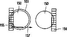
上述焦点误差检测方法需要在所述模块内设置附加部件。仅有焦点检测器部件连同所述检测系统合并在一个构成的检测系统内,以便确定打印质量。如果使用了查找一个点的图像的最小尺寸和最高对比度的焦点误差检测方法,则不需要所述附加部件。就其中最大点尺寸小于0.3mm且透镜具有例如3mm的直径的类似本发明的光学系统而言,在物体小于上述透镜直径的系统中,清晰状态下图像的尺寸为最小且对比度为最大。如果系统散焦,则图像会变大,但其对比度会较低。图13a说明了这一点,图13a示出了检测器部件上的一个点的图像。该图的右侧示出了打印介质在焦点上的情况。点图像150的尺寸是最小的,因此,可覆盖最少量的检测器部件155。图9a的左侧表示打印介质不在焦点上的情况。点图像的尺寸有所增加,但对比度下降,聚焦图像150周围的较轻的环151说明了这一点。在散焦情况下,可覆盖较多数量的检测器部件155。通过比较来自检测器部件155的信号,可以确定点图像的尺寸和对比度。这种测定的信息可用于控制焦点校正电机,因此,所说的尺寸是最大的且对比度是最小的。The focus error detection method described above requires additional components to be provided within the module. Only the focus detector components are incorporated together with the detection system in one constituted detection system in order to determine the print quality. If the focus error detection method that finds the smallest size and highest contrast of the image of a point is used, the additional components are not needed. For an optical system like the present invention where the largest spot size is less than 0.3 mm and the lens has a diameter of eg 3 mm, the size of the image in sharp is smallest and the contrast is largest in the system where the object is smaller than the aforementioned lens diameter. If the system is defocused, the image will be larger, but its contrast will be lower. This is illustrated in Figure 13a, which shows an image of a spot on the detector component. The right side of the figure shows the print medium being in focus. The size of the
假定图像相对检测器是静态的,可对小部分图像测定点图像尺寸和对比度,如图13a所示。当点图像具有不规则的形状时,这种状态是必需的。所以,最好测定整个图像,这一点可通过使图像和检测器如图13b中箭头所示那样彼此相对移动而实现。在图13a和13b中,相同的标号表示相同的部件。Assuming that the image is static with respect to the detector, spot image size and contrast can be determined for a small portion of the image, as shown in Figure 13a. This state is necessary when the point image has an irregular shape. Therefore, it is preferable to measure the entire image, which can be achieved by moving the image and the detector relative to each other as indicated by the arrows in Figure 13b. In Figures 13a and 13b, the same reference numerals denote the same parts.
图13a或13b的焦点误差检测系统具有这样的优点即:可在不对所述模块增加任何附加部件的情况下在监视模块中实现上述系统。带有这种焦点误差检测系统的模块的尺寸仅取决于光学系统的结构,该光学系统用于确定点的尺寸和颜色、打印线的灰度以及打印介质的边缘。所述模块的实际实施例高为25mm、宽为15mm、深为10mm。这种模块非常适于安装在用于打印装置的托架上。The focus error detection system of Figure 13a or 13b has the advantage that the system described above can be implemented in a monitoring module without adding any additional components to said module. The size of a module with such a focus error detection system depends only on the structure of the optical system used to determine the size and color of the dots, the gray scale of the printed line and the edge of the printed medium. A practical embodiment of the module is 25mm high, 15mm wide and 10mm deep. Such a module is very suitable for mounting on a carriage for a printing device.
由于能测定本发明模块的能力,故包括这种模块的打印机具有能就所使用的打印介质的特征自动调整打印机设置的独特特点。通过这种打印机可以获得新颖、经过改进的打印质量。Because of the ability to measure the capabilities of the modules of the present invention, printers incorporating such modules have the unique feature of being able to automatically adjust printer settings to the characteristics of the print media being used. New, improved print quality is available with this printer.
由于不能同时执行所说的测量,故应顺序地进行这些测量。可能的测量顺序如下。在打印机接收到了打印指令之后,就将纸张填加至打印装置的下方。监视模块定位成能在纸经过打印装置时检测纸的顶部。进一步传送纸,直至纸到达用于第一打印线的位置。所述模块检查纸的右侧是否相对打印机正确地对齐。然后,打印机打印若干独立的测试点,这些点是要加以打印的图像的一部分。所述托架移动,直至所述模块测试到纸的左侧。然后,打印机会知道该纸的宽度。此后,托架移回。在这种运动过程中,所述监视器测定测试点的位置、尺寸和颜色。就各个点的测定而言,打印机将所述模块定位至点的上方并聚焦于该点,因此,可获得点的清晰图像。在测定了测试点之后,将它们的平均尺寸、颜色和位置与所存储的参照值相比较。如果出现了偏差,则设置打印机并且将设置存储在打印机的存储器内。通过这种方式,打印机自动地对齐其喷墨盒并对各种介质类型、介质颜色和环境状态获得最大打印质量。然后,打印机准备如打印所需的信息。托架移回至其垂直的起始位置,并且,托架移至左侧,从而,托架会扫描要进行打印的空白纸并检查是否还未打印所说的打印线。如果检测到油墨,则意味着纸张滑动或就双面打即而言填加了错误的纸张。在托架向回扫描过程中,所述模块控制刚刚打印的线并检测所说的点是否位于右侧位置且同时显示正确的灰度。这就能将托架的状态通知给打印机。当所述模块在打印作业过程中经过纸张边缘时,对纸张的位置和方位进行控制。所述模块可以检测在打印装置下方经过的纸张的下侧。将所述模块测出的纸张长度存储在打印机的存储器内。如果后续纸张看起来太长,则打印机会检查是不是因为填进了一张以上的纸。Since the measurements cannot be performed simultaneously, these measurements should be performed sequentially. Possible measurement sequences are as follows. After the printer receives the print command, it feeds the paper to the bottom of the printing device. The monitoring module is positioned to detect the top of the paper as it passes the printing device. The paper is conveyed further until it reaches the position for the first printing line. The module checks that the right side of the paper is properly aligned with respect to the printer. The printer then prints individual test points that are part of the image to be printed. The carriage moves until the module tests to the left side of the paper. The printer then knows the width of that paper. Thereafter, the carriage moves back. During this movement, the monitor determines the position, size and color of the test spot. For the determination of individual dots, the printer positions the module over and focuses on the dot so that a sharp image of the dot is obtained. After the test points have been determined, their average size, color and position are compared with stored reference values. If a deviation occurs, the printer is set and the settings are stored in the printer's memory. In this way, the printer automatically aligns its inkjet cartridges and achieves maximum print quality for a variety of media types, media colors, and environmental conditions. Then, the printer prepares the information as required for printing. The carriage moves back to its vertical home position, and the carriage moves to the left, whereby the carriage scans the blank paper to be printed and checks whether said print line has not been printed. If ink is detected, it means that the paper slipped or the wrong paper was loaded in the case of double-sided printing. During the scan back of the carriage, the module controls the line just printed and detects if the dot in question is in the right position and at the same time displays the correct grayscale. This notifies the printer of the status of the carriage. Controls the position and orientation of the paper as the module passes the edge of the paper during a print job. The module can detect the underside of the paper passing under the printing device. The paper length measured by the module is stored in the memory of the printer. If subsequent sheets appear to be too long, the printer checks to see if more than one sheet has been filled.
业已参照喷墨打印机说明了本发明,但是,这并不意味着本发明仅可以与这种打印机结合使用。本发明可一般地用在任何类型的具有可控打印机设置并可打印能以光学方式检测到的点和打印线的点阵打印机上。The invention has been described with reference to an inkjet printer, however, this does not mean that the invention can only be used in conjunction with such a printer. The present invention can generally be used on any type of dot matrix printer that has controllable printer settings and can print optically detectable dots and print lines.
Claims (22)
Applications Claiming Priority (2)
| Application Number | Priority Date | Filing Date | Title |
|---|---|---|---|
| EP99203874 | 1999-11-19 | ||
| EP99203874.5 | 1999-11-19 |
Publications (2)
| Publication Number | Publication Date |
|---|---|
| CN1344461A CN1344461A (en) | 2002-04-10 |
| CN1185853Ctrue CN1185853C (en) | 2005-01-19 |
Family
ID=8240884
Family Applications (1)
| Application Number | Title | Priority Date | Filing Date |
|---|---|---|---|
| CNB008052794AExpired - Fee RelatedCN1185853C (en) | 1999-11-19 | 2000-11-01 | Multifunction Monitor Module for Printers |
Country Status (6)
| Country | Link |
|---|---|
| US (3) | US6419342B1 (en) |
| EP (1) | EP1149486A1 (en) |
| JP (1) | JP2003515466A (en) |
| KR (1) | KR20010089616A (en) |
| CN (1) | CN1185853C (en) |
| WO (1) | WO2001039486A1 (en) |
Families Citing this family (35)
| Publication number | Priority date | Publication date | Assignee | Title |
|---|---|---|---|---|
| AUPQ056099A0 (en)* | 1999-05-25 | 1999-06-17 | Silverbrook Research Pty Ltd | A method and apparatus (pprint01) |
| AUPQ439299A0 (en) | 1999-12-01 | 1999-12-23 | Silverbrook Research Pty Ltd | Interface system |
| US6561615B2 (en)* | 2001-03-13 | 2003-05-13 | Olympus Optical Co., Ltd. | Image forming apparatus |
| US6779868B2 (en)* | 2001-07-06 | 2004-08-24 | Benq Corporation | Printer with a calibration position positioned within a printing range |
| US7201462B2 (en) | 2002-07-24 | 2007-04-10 | Canon Kabushiki Kaisha | Ink jet printing apparatus and method for correcting ejection driving |
| GB2391199B (en)* | 2002-07-30 | 2006-05-31 | Hewlett Packard Co | Fixer or ink detection in hardcopy apparatus |
| US7055925B2 (en)* | 2003-07-31 | 2006-06-06 | Hewlett-Packard Development Company, L.P. | Calibration and measurement techniques for printers |
| US7370932B2 (en)* | 2004-05-27 | 2008-05-13 | Silverbrook Research Pty Ltd | Cartridge having integrated circuit for enabling validation thereof by a mobile device |
| US7287824B2 (en) | 2004-07-16 | 2007-10-30 | Hewlett-Packard Development Company, L.P. | Method and apparatus for assessing nozzle health |
| JP2006123479A (en)* | 2004-11-01 | 2006-05-18 | Funai Electric Co Ltd | Inkjet printer |
| US7413280B2 (en)* | 2004-12-17 | 2008-08-19 | Konica Minolta Holdings, Inc. | Detection method of interval of recorded positions |
| US20060139670A1 (en)* | 2004-12-27 | 2006-06-29 | Hoblit Robert S | Method and system for correcting output of printer devices |
| US20060152759A1 (en)* | 2005-01-13 | 2006-07-13 | Yen-Fu Chen | Method and system for real-time end-user status and quality monitoring of printing operations |
| US7284921B2 (en) | 2005-05-09 | 2007-10-23 | Silverbrook Research Pty Ltd | Mobile device with first and second optical pathways |
| US7611217B2 (en) | 2005-09-29 | 2009-11-03 | Applied Materials, Inc. | Methods and systems for inkjet drop positioning |
| US20070070109A1 (en)* | 2005-09-29 | 2007-03-29 | White John M | Methods and systems for calibration of inkjet drop positioning |
| US7507981B2 (en)* | 2006-05-30 | 2009-03-24 | Avago Technologies Ecbu Ip (Singapore) Pte. Ltd. | System for identifying a characteristic of a printing media |
| US8305387B2 (en)* | 2007-09-07 | 2012-11-06 | Texas Instruments Incorporated | Adaptive pulse-width modulated sequences for sequential color display systems |
| US20100162285A1 (en)* | 2007-09-11 | 2010-06-24 | Yossef Gerard Cohen | Presence Detector and Method for Estimating an Audience |
| US8526055B1 (en) | 2007-10-22 | 2013-09-03 | Data Recognition Corporation | Standardized test and survey imaging system |
| US9195875B1 (en) | 2007-10-22 | 2015-11-24 | Data Recognition Corporation | Method and apparatus for defining fields in standardized test imaging |
| US8649601B1 (en) | 2007-10-22 | 2014-02-11 | Data Recognition Corporation | Method and apparatus for verifying answer document images |
| US8738659B1 (en) | 2007-10-22 | 2014-05-27 | Data Recognition Corporation | Method and apparatus for managing priority in standardized test and survey imaging |
| US8488220B1 (en)* | 2007-10-22 | 2013-07-16 | Data Recognition Corporation | Method and apparatus for calibrating imaging equipment |
| US7690746B2 (en)* | 2008-03-21 | 2010-04-06 | Xerox Corporation | Systems and methods for detecting print head defects in printing clear ink |
| KR101525800B1 (en)* | 2008-07-25 | 2015-06-10 | 삼성디스플레이 주식회사 | Ink-jet printing system and manufacturing method of display using the same |
| US8125625B2 (en)* | 2009-07-12 | 2012-02-28 | Hewlett-Packard Development Company, L.P. | Hard copy re-emission color measurement system |
| CN101856903B (en)* | 2010-06-08 | 2012-07-18 | 北京公达数码科技有限公司 | Printer with printing quality detecting module and printing quality detecting method thereof |
| EP2626209B1 (en)* | 2012-02-12 | 2018-04-11 | Baumer Inspection GmbH | Method and device for detecting malfunctions of nozzles of an ink-jet printer |
| JP6050838B2 (en)* | 2012-03-02 | 2016-12-21 | オセ−テクノロジーズ・ベー・フェー | Dot detection method and color image reproduction apparatus |
| JP6225517B2 (en)* | 2013-07-08 | 2017-11-08 | 株式会社リコー | Droplet discharge state detection apparatus and image forming apparatus |
| ITVR20130226A1 (en)* | 2013-10-11 | 2015-04-12 | Projecta Engineering S R L | DECORATION LINE |
| US10139340B2 (en)* | 2015-06-29 | 2018-11-27 | Hannu Harjunmaa | Noninvasive refractometer |
| CN108665974A (en)* | 2018-06-25 | 2018-10-16 | 天津起跑线生物信息技术有限公司 | A kind of detection of biological samples and reporting system |
| US11468554B2 (en) | 2019-10-18 | 2022-10-11 | Electronics For Imaging, Inc. | Assessing printer quality by assigning quality scores to images |
Family Cites Families (17)
| Publication number | Priority date | Publication date | Assignee | Title |
|---|---|---|---|---|
| US4547784A (en) | 1984-12-24 | 1985-10-15 | Polaroid Corporation | Thermal recording system and method |
| JPS6469159A (en)* | 1987-09-10 | 1989-03-15 | Minolta Camera Kk | Picture reader |
| US5737090A (en) | 1993-02-25 | 1998-04-07 | Ohio Electronic Engravers, Inc. | System and method for focusing, imaging and measuring areas on a workpiece engraved by an engraver |
| US5508826A (en)* | 1993-04-27 | 1996-04-16 | Lloyd; William J. | Method and apparatus for calibrated digital printing using a four by four transformation matrix |
| US5451990A (en)* | 1993-04-30 | 1995-09-19 | Hewlett-Packard Company | Reference pattern for use in aligning multiple inkjet cartridges |
| DE69417319T2 (en) | 1993-08-30 | 1999-07-15 | Hewlett-Packard Co., Palo Alto, Calif. | Image scanning head for a thermal inkjet printer |
| US5532825A (en) | 1993-08-30 | 1996-07-02 | Hewlett-Packard Company | Add-on scanner for existing ink jet printer |
| US5633672A (en) | 1994-09-13 | 1997-05-27 | Eastman Kodak Company | Real-time calibration of processless writer |
| JP2907772B2 (en)* | 1995-05-30 | 1999-06-21 | キヤノン株式会社 | Method and apparatus for measuring ink ejection amount, printing apparatus, and method for measuring ink ejection amount in printing apparatus |
| US5745131A (en)* | 1995-08-03 | 1998-04-28 | Xerox Corporation | Gray scale ink jet printer |
| KR100191040B1 (en)* | 1995-09-14 | 1999-06-15 | 미따라이 하지메 | Scanner head cartridges and information processing units to which these scanner head cartridges can be mounted |
| JPH09109380A (en)* | 1995-10-20 | 1997-04-28 | Brother Ind Ltd | Inkjet printer |
| US5856833A (en) | 1996-12-18 | 1999-01-05 | Hewlett-Packard Company | Optical sensor for ink jet printing system |
| JPH11284815A (en)* | 1998-03-31 | 1999-10-15 | Nec Home Electron Ltd | Image input device |
| JPH11312213A (en)* | 1998-04-30 | 1999-11-09 | Toshiba Tec Corp | Symbol reader |
| US6227644B1 (en)* | 1998-05-04 | 2001-05-08 | Hewlett-Packard Company | Inkjet dot imaging sensor for the calibration of inkjet print heads |
| US6378976B1 (en)* | 1999-08-23 | 2002-04-30 | Hewlett-Packard Company | Use of an essentially colorless marker to allow evaluation of nozzle health for printing colorless “fixer” agents in multi-part ink-jet images |
- 2000
- 2000-09-25USUS09/668,540patent/US6419342B1/ennot_activeExpired - Fee Related
- 2000-11-01JPJP2001540510Apatent/JP2003515466A/enactivePending
- 2000-11-01KRKR1020017009114Apatent/KR20010089616A/ennot_activeCeased
- 2000-11-01EPEP00975976Apatent/EP1149486A1/ennot_activeWithdrawn
- 2000-11-01WOPCT/EP2000/010759patent/WO2001039486A1/ennot_activeApplication Discontinuation
- 2000-11-01CNCNB008052794Apatent/CN1185853C/ennot_activeExpired - Fee Related
- 2002
- 2002-05-23USUS10/154,673patent/US20020145641A1/ennot_activeAbandoned
- 2003
- 2003-04-28USUS10/424,634patent/US6948793B2/ennot_activeExpired - Fee Related
Also Published As
| Publication number | Publication date |
|---|---|
| US20020145641A1 (en) | 2002-10-10 |
| CN1344461A (en) | 2002-04-10 |
| WO2001039486A1 (en) | 2001-05-31 |
| EP1149486A1 (en) | 2001-10-31 |
| JP2003515466A (en) | 2003-05-07 |
| US20030202029A1 (en) | 2003-10-30 |
| KR20010089616A (en) | 2001-10-06 |
| US6419342B1 (en) | 2002-07-16 |
| US6948793B2 (en) | 2005-09-27 |
Similar Documents
| Publication | Publication Date | Title |
|---|---|---|
| CN1185853C (en) | Multifunction Monitor Module for Printers | |
| JP4080000B2 (en) | Optical sensor for ink jet printing system | |
| CN1282550C (en) | Liquid container with identifying means and method for detecting state of mount of liquid container | |
| US7055925B2 (en) | Calibration and measurement techniques for printers | |
| US10207495B2 (en) | Image forming apparatus, method for calculating actual distance of deviation, and computer program product storing same | |
| US6523920B2 (en) | Combination ink jet pen and optical scanner head and methods of improving print quality | |
| US8009187B2 (en) | Lens sheet and printer | |
| US20080170239A1 (en) | Light Source Unit For Alignment, Alignment Apparatus, Exposure Apparatus, Digital Exposure Apparatus, Alignment Method, Exposure Method And Method For Setting Lighting Apparatus Condition | |
| JP2008066850A (en) | Method for adjusting position of light receiving element array substrate provided in contact image sensor, method for manufacturing contact image sensor, and contact image sensor | |
| JP2004524192A (en) | How to monitor printers and printer processing | |
| CN1957247A (en) | Optical system for generating illumination strips | |
| US7794073B2 (en) | Ink jet printer | |
| US7057634B2 (en) | Multi-beam scanning device and image forming apparatus using the scanning device | |
| US6485124B1 (en) | Optical alignment method and detector | |
| CN107867065B (en) | Liquid ejecting apparatus, color measuring method, and method of driving liquid ejecting apparatus | |
| JP2003035599A (en) | Color correction system based on color image forming bar used for color control system in color printer and spectrophotometer | |
| JP6996225B2 (en) | Imaging device, image forming device, actual distance calculation method, and program | |
| JP4844142B2 (en) | Printer | |
| US6922269B2 (en) | Light scanning unit | |
| JPH1134388A (en) | Image forming apparatus | |
| CN1744134A (en) | Identification device | |
| JP2023116346A (en) | Image forming apparatus, image forming method and program | |
| JP2009104154A (en) | Lens sheet |
Legal Events
| Date | Code | Title | Description |
|---|---|---|---|
| C06 | Publication | ||
| PB01 | Publication | ||
| C10 | Entry into substantive examination | ||
| SE01 | Entry into force of request for substantive examination | ||
| C10 | Entry into substantive examination | ||
| SE01 | Entry into force of request for substantive examination | ||
| C14 | Grant of patent or utility model | ||
| GR01 | Patent grant | ||
| C19 | Lapse of patent right due to non-payment of the annual fee | ||
| CF01 | Termination of patent right due to non-payment of annual fee |