CN1180259C - biological sensor - Google Patents
biological sensorDownload PDFInfo
- Publication number
- CN1180259C CN1180259CCNB018022340ACN01802234ACN1180259CCN 1180259 CCN1180259 CCN 1180259CCN B018022340 ACNB018022340 ACN B018022340ACN 01802234 ACN01802234 ACN 01802234ACN 1180259 CCN1180259 CCN 1180259C
- Authority
- CN
- China
- Prior art keywords
- filter membrane
- sample
- sample solution
- electrode system
- substrate
- Prior art date
- Legal status (The legal status is an assumption and is not a legal conclusion. Google has not performed a legal analysis and makes no representation as to the accuracy of the status listed.)
- Expired - Fee Related
Links
Images


Classifications
- C—CHEMISTRY; METALLURGY
- C12—BIOCHEMISTRY; BEER; SPIRITS; WINE; VINEGAR; MICROBIOLOGY; ENZYMOLOGY; MUTATION OR GENETIC ENGINEERING
- C12Q—MEASURING OR TESTING PROCESSES INVOLVING ENZYMES, NUCLEIC ACIDS OR MICROORGANISMS; COMPOSITIONS OR TEST PAPERS THEREFOR; PROCESSES OF PREPARING SUCH COMPOSITIONS; CONDITION-RESPONSIVE CONTROL IN MICROBIOLOGICAL OR ENZYMOLOGICAL PROCESSES
- C12Q1/00—Measuring or testing processes involving enzymes, nucleic acids or microorganisms; Compositions therefor; Processes of preparing such compositions
- C12Q1/001—Enzyme electrodes
- C12Q1/004—Enzyme electrodes mediator-assisted
- G—PHYSICS
- G01—MEASURING; TESTING
- G01N—INVESTIGATING OR ANALYSING MATERIALS BY DETERMINING THEIR CHEMICAL OR PHYSICAL PROPERTIES
- G01N27/00—Investigating or analysing materials by the use of electric, electrochemical, or magnetic means
- G01N27/26—Investigating or analysing materials by the use of electric, electrochemical, or magnetic means by investigating electrochemical variables; by using electrolysis or electrophoresis
- G01N27/28—Electrolytic cell components
- G01N27/30—Electrodes, e.g. test electrodes; Half-cells
- G01N27/327—Biochemical electrodes, e.g. electrical or mechanical details for in vitro measurements
- G01N27/3271—Amperometric enzyme electrodes for analytes in body fluids, e.g. glucose in blood
- G01N27/3272—Test elements therefor, i.e. disposable laminated substrates with electrodes, reagent and channels
Landscapes
- Chemical & Material Sciences (AREA)
- Life Sciences & Earth Sciences (AREA)
- Health & Medical Sciences (AREA)
- Organic Chemistry (AREA)
- Wood Science & Technology (AREA)
- Molecular Biology (AREA)
- Proteomics, Peptides & Aminoacids (AREA)
- Zoology (AREA)
- Physics & Mathematics (AREA)
- Analytical Chemistry (AREA)
- Biochemistry (AREA)
- General Health & Medical Sciences (AREA)
- Biophysics (AREA)
- Immunology (AREA)
- Engineering & Computer Science (AREA)
- Electrochemistry (AREA)
- Pathology (AREA)
- Biotechnology (AREA)
- Microbiology (AREA)
- General Physics & Mathematics (AREA)
- Chemical Kinetics & Catalysis (AREA)
- Hematology (AREA)
- Bioinformatics & Cheminformatics (AREA)
- General Engineering & Computer Science (AREA)
- Genetics & Genomics (AREA)
- Investigating Or Analysing Biological Materials (AREA)
- Apparatus Associated With Microorganisms And Enzymes (AREA)
- Measuring Or Testing Involving Enzymes Or Micro-Organisms (AREA)
Abstract
Translated fromChineseDescription
Translated fromChinese技术领域technical field
本发明涉及能够迅速且简便地对试样中的测定对象进行高精度定量的生物传感器。The present invention relates to a biosensor capable of quickly and easily quantifying a measurement target in a sample with high precision.
背景技术Background technique
以往,作为不用对试样溶液进行稀释和搅拌等处理就能够对试样中的特定成分进行定量的方法,揭示了以下所述的生物传感器(日本专利公开公报平2-062952号)。Conventionally, a biosensor described below has been disclosed as a method capable of quantifying a specific component in a sample without diluting or stirring the sample solution (Japanese Patent Laid-Open Publication No. Hei 2-062952).
该生物传感器的绝缘性基板上通过丝网印刷等方法形成了由测定电极、工作电极、配极及参考电极组成的电极系,该电极系上则形成了包含亲水性高分子、氧化还原酶及导电体的酶反应层。根据需要可在该酶反应层中添加缓冲剂。On the insulating substrate of the biosensor, an electrode system composed of a measuring electrode, a working electrode, a counter electrode and a reference electrode is formed by screen printing and other methods. And the enzyme reaction layer of the conductor. A buffer can be added to this enzyme reaction layer as needed.
如果在以上制得的生物传感器的酶反应层上滴加含有底物的试样溶液,则酶反应层溶解,酶与底物反应,导电体随之还原。酶反应结束后,该被还原的导电体又通过电化学方法氧化,由此时获得的氧化电流值可求得试样溶液中的底物浓度。When the sample solution containing the substrate is dropped on the enzyme reaction layer of the biosensor prepared above, the enzyme reaction layer dissolves, the enzyme reacts with the substrate, and the conductor is reduced accordingly. After the enzymatic reaction, the reduced conductor is oxidized electrochemically, and the substrate concentration in the sample solution can be obtained from the oxidation current value obtained at this time.
上述生物传感器的原理是以测定对象物质为底物,通过对酶进行选择对各种不同的物质进行测定。例如,如果使用葡萄糖氧化酶为氧化还原酶,则能够构成可对血液中的葡萄糖浓度进行测定的生物传感器。该传感器作为葡萄糖传感器被广泛使用。此外,如果使用胆甾醇氧化酶,则能够构成可对血清中的胆甾醇进行测定的生物传感器。The principle of the above-mentioned biosensor is to measure various substances by selecting an enzyme as a substrate with a substance to be measured. For example, if glucose oxidase is used as the oxidoreductase, a biosensor capable of measuring the glucose concentration in blood can be constructed. This sensor is widely used as a glucose sensor. In addition, by using cholesterol oxidase, a biosensor capable of measuring serum cholesterol can be constructed.
通常,作为诊断基准使用的血清胆甾醇值是胆甾醇和胆甾醇酯的浓度合计值。胆甾醇酯不会成为因胆甾醇氧化酶而进行的氧化反应的底物。因此,要对作为诊断基准的血清胆甾醇值进行测定,就必须有使胆甾醇酯转变为胆甾醇的过程。该过程中以胆甾醇酯酶作为催化剂。Usually, the serum cholesterol value used as a diagnostic standard is the sum of the concentrations of cholesterol and cholesteryl esters. Cholesteryl esters do not serve as substrates for oxidation reactions by cholesterol oxidase. Therefore, in order to measure the serum cholesterol value as a diagnostic benchmark, there must be a process of converting cholesteryl esters into cholesterol. In this process, cholesterol esterase is used as a catalyst.
使用酶反应层中包含胆甾醇酯酶和胆甾醇氧化酶的生物传感器,可测定血清中的总胆甾醇浓度。Using a biosensor comprising cholesterol esterase and cholesterol oxidase in an enzyme reaction layer, the total cholesterol concentration in serum can be measured.
但是,在进行胆甾醇的测定时会受到细胞膜中存在的胆甾醇的影响。此外,反应试剂中的胆甾醇酯酶最好与可提高反应性的表面活性剂共存。在大多数情况下,由于表面活性剂会破坏细胞膜,所以细胞内的物质可能会直接或间接地对酶反应或电极产生影响。基于此,胆甾醇传感器的酶反应及其后的电极反应都最好在血浆或血清中进行。除了胆甾醇传感器之外,有时血液中血细胞的存在会对感应值产生影响,理想的情况是在不含血细胞的溶液中进行酶反应和电极反应。However, the measurement of cholesterol is affected by the cholesterol present in the cell membrane. In addition, cholesterol esterase in the reaction reagent is preferably coexisted with a surfactant that can improve reactivity. In most cases, since surfactants disrupt cell membranes, substances inside cells may directly or indirectly affect enzyme reactions or electrodes. Based on this, the enzymatic reaction of the cholesterol sensor and the subsequent electrode reaction are best carried out in plasma or serum. In addition to the cholesterol sensor, sometimes the presence of blood cells in the blood has an effect on the sensing value, and it is ideal to perform the enzyme reaction and the electrode reaction in a solution that does not contain blood cells.
从全血中分离出血浆或血清时一般采用离心分离的方法。但是,进行离心分离需要时间,且操作复杂。Centrifugation is generally used to separate plasma or serum from whole blood. However, centrifugation requires time and is complicated.
美国专利第3,607,092号揭示了血液试验中的膜片。该膜片具有可使溶液透过但无法使血细胞等固体和蛋白质等大分子透过的薄膜层,因此,利用该薄膜可除去血细胞。但是,随着血液的透过薄膜上蓄积了大量固体成分,所以为了获得上述生物传感器的反应所必须的滤液,需要面积更大的薄膜层。因此,前述薄膜并不一定适用。US Patent No. 3,607,092 discloses a membrane in a blood test. The membrane has a thin film layer that is permeable to solutions but impermeable to solids such as blood cells and macromolecules such as proteins, so blood cells can be removed by using this film. However, since a large amount of solid matter accumulates on the membrane as the blood permeates, a membrane layer with a larger area is required to obtain the filtrate necessary for the reaction of the above-mentioned biosensor. Therefore, the aforementioned films are not necessarily suitable.
美国专利第4,477,575号揭示了利用玻璃纤维滤膜使全血通过以分离出血清的装置及方法。这种利用纤维和多孔体形成的滤膜从全血中分离出血清的方法可能适用于上述生物传感器。但是,该方法中的滤膜并不能够阻挡血细胞,只能够简单地减慢其流速,实际上只完成了血细胞和血浆的分离。因此,为了使该方法适用于上述生物传感器,在血细胞未从滤膜流出的过程中必须获得生物传感器的反应所必须的量以上的通过滤膜过滤的血浆或血清。这样就必须使滤膜的血液流动方向的长度的设定满足上述条件。US Patent No. 4,477,575 discloses a device and method for separating serum by passing whole blood through a glass fiber filter membrane. This method of separating serum from whole blood using a filter membrane formed of fibers and porous bodies may be applicable to the above-mentioned biosensor. However, the filter membrane in this method cannot block blood cells, but simply slows down its flow rate, and in fact only completes the separation of blood cells and plasma. Therefore, in order to apply this method to the above-mentioned biosensor, it is necessary to obtain plasma or serum filtered through the filter membrane in an amount more than necessary for the reaction of the biosensor while blood cells do not flow out of the filter membrane. Thus, the length of the filter membrane in the blood flow direction must be set to meet the above conditions.
将满足上述条件的滤膜设置在生物传感器的配置了电极系及反应试剂系统的部位及供给作为试样的血液的部位之间,就能够构成具有血细胞过滤能力的生物传感器。图9所示即为该传感器的一个例子,图9为除去了反应试剂层的分解立体图。A biosensor capable of filtering blood cells can be constructed by disposing a filter membrane satisfying the above conditions between the part of the biosensor where the electrode system and the reaction reagent system are arranged and the part where blood is supplied as a sample. An example of the sensor is shown in FIG. 9, which is an exploded perspective view with the reagent layer removed.
图9中,在由聚对苯二甲酸乙二醇酯形成的绝缘性基板101上通过丝网印刷法涂布银糊,形成导电片102和103及电极系的底层。然后,在基板101上涂布含有树脂粘合剂的导电性碳糊形成包括工作电极104和配极105的电极系。此外,通过涂布绝缘糊形成绝缘层106。工作电极104和配极105分别与导电片102和导电片103相连。工作电极104及配极105的露出部分面积一定,且绝缘层106覆盖部分导电片。In FIG. 9, a silver paste is applied by screen printing on an insulating substrate 101 made of polyethylene terephthalate to form conductive sheets 102 and 103 and a bottom layer of the electrode system. Then, a conductive carbon paste containing a resin binder is coated on the substrate 101 to form an electrode system including the working electrode 104 and the counter electrode 105 . In addition, the insulating layer 106 is formed by applying an insulating paste. The working electrode 104 and the counter electrode 105 are connected to the conductive sheet 102 and the conductive sheet 103 respectively. The exposed parts of the working electrode 104 and the counter electrode 105 have a constant area, and the insulating layer 106 covers part of the conductive sheet.
以上形成了电极系的绝缘性基板101、具有气孔109的罩子108、隔板107及具有血细胞过滤功能的滤膜111按照图中点划线所示的位置关系相连形成生物传感器。滤膜111嵌合在罩子108和绝缘性基板101间由隔板107的狭缝110形成的试样溶液供给通道中。113a表示滤膜111的与绝缘性基板接触的部分。滤膜111不覆盖前述试样溶液通道中的由工作电极104和配极105形成的电极系,而是被设置在电极系和基板上的试样供给部位112间。The insulating substrate 101 formed with the electrode system, the cover 108 with air holes 109, the separator 107, and the filter membrane 111 with blood cell filtration function are connected according to the positional relationship shown by the dotted line in the figure to form a biosensor. The filter membrane 111 is fitted into a sample solution supply channel formed by the slit 110 of the spacer 107 between the cover 108 and the insulating substrate 101 . 113a denotes a portion of the filter membrane 111 that is in contact with the insulating substrate. The filter membrane 111 does not cover the electrode system formed by the working electrode 104 and the counter electrode 105 in the sample solution channel, but is placed between the electrode system and the sample supply portion 112 on the substrate.
在以上构成的生物传感器的试样供给部位112滴下血液,血液从滤膜111的试样供给部位的端部渗入其内部。由于滤膜内血细胞的渗透速度比作为液体成分的血浆慢,所以血浆从滤膜的电极系端部渗出。渗出的血浆一边使位于覆盖电极的位置或其上的罩子内面的由酶等组成的反应试剂溶解,一边填满到气孔109为止的整个试样溶液供给通道。当整个试样溶液供给通道被液体填满后,滤膜111内的液体也停止流动,此时血细胞未到达滤膜的电极系端部,而是停留在原来的位置。Blood is dripped on the sample supply portion 112 of the biosensor configured as above, and the blood seeps into the inside of the filter membrane 111 from the end of the sample supply portion. Since the permeation speed of the blood cells in the filter membrane is slower than that of plasma as a liquid component, the plasma seeps out from the end of the electrode system of the filter membrane. The oozing plasma fills the entire sample solution supply channel up to the air hole 109 while dissolving the reaction reagent composed of enzyme or the like at the position covering the electrodes or on the inner surface of the cover above. When the entire sample solution supply channel is filled with liquid, the liquid in the filter membrane 111 also stops flowing. At this time, the blood cells do not reach the end of the electrode system of the filter membrane, but stay at the original position.
这样经过血细胞的过滤,血浆溶解的反应试剂层与血浆中的测定成分发生化学反应,如果是胆甾醇传感器就与胆甾醇发生化学反应,经过一定时间后,利用电极反应测定电流值,再由此测定血浆中的成分。In this way, through the filtration of blood cells, the reaction reagent layer dissolved in the plasma reacts chemically with the measured components in the plasma. If it is a cholesterol sensor, it reacts chemically with cholesterol. After a certain period of time, the electrode reaction is used to measure the current value, and then Determination of components in plasma.
但是,在该生物传感器的试样供给部位112滴下的血液的一部分未被滤膜111的试样供给部位端部吸收,而是被转移到试样溶液供给通道和滤膜111的接触部位,这样包含血细胞成分的血液直接到达反应试剂层,其结果是,血细胞或血细胞内的成分与反应试剂发生反应,使测定值出现误差。However, part of the blood dripped from the sample supply site 112 of the biosensor is not absorbed by the sample supply site end of the filter membrane 111, but is transferred to the contact site between the sample solution supply channel and the filter membrane 111, thus Blood containing blood cell components directly reaches the reaction reagent layer, and as a result, the blood cells or components in the blood cells react with the reaction reagent, causing errors in measured values.
用粘合剂粘合滤膜111和试样溶液供给通道的接触部分可防止以上血液被转移到滤膜111和试样溶液供给通道的间隙的现象。Bonding the contact portion of the filter membrane 111 and the sample solution supply channel with an adhesive can prevent the above phenomenon that blood is transferred to the gap between the filter membrane 111 and the sample solution supply channel.
但是,所用粘合剂可能会改变血液成分。此外,滤膜111表面或试样溶液供给通道的接触部位需要涂布粘合剂,这样制作工序就会变得复杂。However, the adhesive used may alter blood composition. In addition, the surface of the filter membrane 111 or the contact portion of the sample solution supply channel needs to be coated with an adhesive, which complicates the manufacturing process.
本发明的目的是对具备可使血细胞等固形成分过滤的滤膜的生物传感器进行改进,解决以往技术中存在的上述问题。The object of the present invention is to improve a biosensor equipped with a filter membrane capable of filtering solid components such as blood cells, so as to solve the above-mentioned problems in the prior art.
本发明的目的是使传感器中添加的试样渗透入滤膜内,但仅使透过滤膜的试样溶液到达反应试剂层及电极系,以此提供能够显现稳定的感应性的生物传感器。The object of the present invention is to provide a biosensor capable of exhibiting stable sensitivity by allowing the sample added to the sensor to permeate into the filter membrane, but allowing only the sample solution passing through the filter membrane to reach the reaction reagent layer and the electrode system.
发明的揭示disclosure of invention
本发明的生物传感器具备绝缘性基板、设置在前述基板上的至少具有工作电极和配极的电极系、与前述基板组合形成将试样溶液从试样供给部位导向前述电极系的试样溶液供给通道的覆盖部件、至少包含氧化还原酶和导电体的反应试剂系统、设置在前述试样溶液供给通道的电极系和试样供给部位间的滤膜,该生物传感器的特征是,从前述滤膜的试样供给部位的端部到电极系的端部的区域内具有包围滤膜表面的空隙部分。The biosensor of the present invention includes an insulating substrate, an electrode system having at least a working electrode and a counter electrode provided on the substrate, and a sample solution supply for guiding a sample solution from a sample supply site to the electrode system in combination with the substrate. A channel covering member, a reaction reagent system including at least an oxidoreductase and a conductor, and a filter membrane provided between the electrode system of the sample solution supply channel and the sample supply site, the biosensor is characterized in that the filter membrane In the region from the end of the sample supply portion to the end of the electrode system, there is a void portion surrounding the surface of the filter membrane.
较好的实施方式中,前述试样供给部位被设置在前述基板上,前述试样溶液供给通道沿基板及覆盖部件配置。更好是前述试样供给部位位于前述电极系的一侧。In a preferred embodiment, the sample supply portion is provided on the substrate, and the sample solution supply channel is arranged along the substrate and the cover member. More preferably, the sample supply portion is located on one side of the electrode system.
该实施方式中,包围前述滤膜表面的空隙部分宽度最好在0.5mm以上。前述空隙部分宽度如果小于0.5mm,则转移到形成试样溶液供给通道的基板及/或覆盖部件和滤膜的间隙的血液可能会因毛细管作用进入空隙部分。更好的是空隙部分宽度在0.5mm~5.0mm的范围内。如果超过5.0mm,则使传感器振动的情况下滤膜可能会变形。前述空隙部分宽度最好在1.0mm~3.0mm的范围内。In this embodiment, the width of the void surrounding the surface of the filter membrane is preferably 0.5 mm or more. If the width of the gap is less than 0.5 mm, blood transferred to the substrate forming the sample solution supply channel and/or the gap between the cover member and the filter membrane may enter the gap due to capillary action. More preferably, the width of the void portion is in the range of 0.5 mm to 5.0 mm. If it exceeds 5.0 mm, the filter membrane may be deformed when the sensor is vibrated. It is preferable that the width of the aforementioned void portion is in the range of 1.0 mm to 3.0 mm.
其他较好的实施方式中,前述试样供给部位被设置于前述覆盖部件,前述试样溶液供给通道从试样供给部位开始沿重力方向配置。该实施方式中,包围滤膜表面的空隙部分的宽度最好在100μm以上,小于前述滤膜的厚度。In another preferred embodiment, the sample supply portion is provided on the cover member, and the sample solution supply channel is arranged along the gravitational direction from the sample supply portion. In this embodiment, the width of the void surrounding the surface of the filter membrane is preferably more than 100 μm, which is smaller than the thickness of the aforementioned filter membrane.
所用滤膜由具备三维相连的空隙部分的多孔体形成,该多孔体通过毛细管作用将血液从前述试样供给部位转移到试样溶液供给通道,并具备利用血浆和血细胞的流动阻力差对血细胞进行过滤的作用。该滤膜可采用玻璃纤维、纤维素、纸浆等亲水性纤维形成的非织造布、滤纸及其他多孔体。The filter membrane used is formed of a porous body having a three-dimensionally connected void portion, and the porous body transfers blood from the aforementioned sample supply site to the sample solution supply channel by capillary action, and has the ability to utilize the flow resistance difference between plasma and blood cells to conduct blood cells. The role of filtering. The filter membrane can be non-woven fabric formed of hydrophilic fibers such as glass fiber, cellulose, pulp, etc., filter paper and other porous bodies.
本发明适用于以胆甾醇氧化酶为氧化还原酶的胆甾醇传感器。The invention is suitable for a cholesterol sensor using cholesterol oxidase as an oxidoreductase.
胆甾醇传感器的前述反应试剂系统中最好包含能够对胆甾醇酯进行分解的酶。这种能够对胆甾醇酯进行水解的酶最好为胆甾醇酯酶,前述反应试剂系统中最好还包含表面活性剂。The reaction reagent system of the cholesterol sensor preferably contains an enzyme capable of decomposing cholesteryl ester. The enzyme capable of hydrolyzing cholesteryl ester is preferably cholesterol esterase, and the aforementioned reaction reagent system preferably also contains a surfactant.
前述覆盖部件及前述绝缘性基板的部分或全部最好是透明的。Part or all of the cover member and the insulating substrate are preferably transparent.
对附图的简单说明A brief description of the attached drawings
图1为本发明实施方式之一的生物传感器的除去了反应试剂的分解立体图。FIG. 1 is an exploded perspective view of a biosensor according to one embodiment of the present invention, with a reaction reagent removed.
图2为同一生物传感器的纵截面图。Fig. 2 is a longitudinal sectional view of the same biosensor.
图3为本发明另一实施方式中的生物传感器的主要部分的平面图。Fig. 3 is a plan view of main parts of a biosensor in another embodiment of the present invention.
图4为本发明另一实施方式中的生物传感器的纵截面图。Fig. 4 is a longitudinal sectional view of a biosensor in another embodiment of the present invention.
图5为本发明又一实施方式中的生物传感器的纵截面图。Fig. 5 is a longitudinal sectional view of a biosensor in still another embodiment of the present invention.
图6为同一传感器的分解立体图。Fig. 6 is an exploded perspective view of the same sensor.
图7为本发明另一实施方式中的生物传感器的纵截面图。Fig. 7 is a longitudinal sectional view of a biosensor in another embodiment of the present invention.
图8为同一生物传感器的分解立体图。Fig. 8 is an exploded perspective view of the same biosensor.
图9为已有技术中的生物传感器除去了反应试剂层的分解立体图。Fig. 9 is an exploded perspective view of a biosensor in the prior art with the reaction reagent layer removed.
实施发明的最佳方式The best way to practice the invention
如上所述,本发明的生物传感器的基板和覆盖部件间形成的试样溶液供给通道中具备设置在基板或覆盖部件侧的试样供给部位和基板上的电极系间的滤膜。从前述滤膜的试样供给部位的端部到电极系的端部的区域内具有包围滤膜表面的空隙部分。即,滤膜表面的周围设置了不与形成试样溶液供给通道的基板及覆盖部件接触的区域。As described above, the sample solution supply channel formed between the substrate and the cover member of the biosensor of the present invention includes a filter membrane provided between the sample supply portion on the substrate or the cover member side and the electrode system on the substrate. In the region from the end of the sample supply portion of the filter membrane to the end of the electrode system, there is a void portion surrounding the surface of the filter membrane. That is, a region not in contact with the substrate and the cover member forming the sample solution supply channel is provided around the surface of the filter membrane.
从某种角度看,本发明的生物传感器具备绝缘性基板、设置在前述基板上的至少具有工作电极和配极的电极系、与前述基板组合形成将试样溶液从基板上的试样供给部位导向前述电极系的试样溶液供给通道的覆盖部件、至少包含氧化还原酶和导电体的设置在前述电极系上或其附近的反应试剂系统、设置在前述试样溶液供给通道的电极系和试样供给部位间的滤膜,从前述滤膜的试样供给部位的端部到电极系的端部的区域内具有包围滤膜表面的空隙部分。Viewed from a certain point of view, the biosensor of the present invention has an insulating substrate, an electrode system having at least a working electrode and a counter electrode disposed on the substrate, and a sample supply part for feeding a sample solution from the substrate in combination with the substrate. A cover member for a sample solution supply channel leading to the electrode system, a reaction reagent system provided on or near the electrode system including at least an oxidoreductase and a conductor, an electrode system and a reagent system provided in the sample solution supply channel The filter membrane between the sample supply locations has a void portion surrounding the surface of the filter membrane in the region from the end of the sample supply location of the filter membrane to the end of the electrode system.
从另一角度看,本发明的生物传感器具备绝缘性基板、设置在前述基板上的至少具有工作电极和配极的电极系、与前述基板组合的覆盖部件、形成于前述覆盖部件和基板间的将试样溶液从前述覆盖部件的试样供给部位导向基板上的电极系的试样溶液供给通道、至少包含氧化还原酶和导电体的设置在前述电极系上或其附近的反应试剂系统、设置在前述试样溶液供给通道的电极系和试样供给部位间的滤膜,从前述滤膜的试样供给部位的端部到电极系的端部的区域内具有包围滤膜表面的空隙部分。Viewed from another perspective, the biosensor of the present invention includes an insulating substrate, an electrode system having at least a working electrode and a counter electrode disposed on the substrate, a cover member combined with the substrate, and an electrode system formed between the cover member and the substrate. The sample solution supply channel of the electrode system on the substrate that guides the sample solution from the sample supply portion of the cover member to the substrate, a reaction reagent system that includes at least an oxidoreductase and a conductor and is provided on or near the electrode system, and The filter membrane between the electrode system and the sample supply portion of the sample solution supply channel has a void surrounding the surface of the filter membrane in a region from the end of the sample supply portion of the filter membrane to the end of the electrode system.
上述构造使滴在试样供给部位的血液等试样溶液被前述滤膜吸收,血细胞等固形成分则被前述滤膜过滤,将试样溶液沿试样溶液供给通道导向电极系及反应试剂层。其结果是,仅血细胞等固形成分被过滤了的试样溶液到达了电极系。在试样溶液供给通道的试样供给部位附近,有时部分试样溶液不是被滤膜吸收,而是从滤膜和试样溶液供给通道的接触部分的细小缝隙直接流入试样溶液供给通道内。但是,这部分试样溶液在包围前述滤膜表面的空隙部分被阻挡,不能够进入其上的电极系。因此,含有血细胞等固形成分的试样溶液不会从设有空隙部分的区域流向电极系。在试样溶液供给通道中,反应试剂层最好设置在电极系上或其附近。The above-mentioned structure makes the sample solution such as blood dripped on the sample supply part absorbed by the filter membrane, and the solid components such as blood cells are filtered by the filter membrane, and the sample solution is guided to the electrode system and the reaction reagent layer along the sample solution supply channel. As a result, only the sample solution from which solid components such as blood cells have been filtered reaches the electrode system. In the vicinity of the sample supply portion of the sample solution supply channel, part of the sample solution may not be absorbed by the filter membrane, but flow directly into the sample solution supply channel from a small gap between the filter membrane and the contact portion of the sample solution supply channel. However, this part of the sample solution is blocked by the void portion surrounding the surface of the filter membrane, and cannot enter the electrode system thereon. Therefore, the sample solution containing solid components such as blood cells does not flow to the electrode system from the region where the void is provided. In the sample solution supply channel, the reaction reagent layer is preferably provided on or near the electrode system.
构成反应试剂系统的氧化还原酶可采用各种不同的酶,例如,葡萄糖氧化酶、乳酸氧化酶、胆甾醇氧化酶等。As the oxidoreductase constituting the reaction reagent system, various enzymes can be used, for example, glucose oxidase, lactate oxidase, cholesterol oxidase and the like.
测定血清胆甾醇值时,采用胆甾醇氧化酶和能够使胆甾醇酯水解的酶。可使胆甾醇酯水解的酶包括胆甾醇酯酶和脂蛋白脂肪酶等。特别是胆甾醇酯酶,在使用了适当的表面活性剂的情况下,可迅速将胆甾醇酯转变为胆甾醇。When measuring the serum cholesterol level, cholesterol oxidase and an enzyme capable of hydrolyzing cholesterol esters are used. Enzymes that can hydrolyze cholesterol esters include cholesterol esterase and lipoprotein lipase. Cholesteryl esterase, in particular, can rapidly convert cholesteryl esters into cholesterol when appropriate surfactants are used.
使用可使胆甾醇酯水解的酶时,如果使反应试剂中包含可提高酶活性的表面活性剂,则可大大缩短酶反应所需时间。When an enzyme capable of hydrolyzing cholesteryl ester is used, the time required for the enzyme reaction can be greatly shortened if a surfactant that increases the activity of the enzyme is included in the reaction reagent.
例如,可使胆甾醇酯酶的活性得到提高的表面活性剂包括正辛基-β-D-硫葡糖苷、聚乙二醇一月桂醚、胆酸钠、月桂基-β-麦芽糖苷、蔗糖-一月桂酸酯、脱氧胆酸钠、牛磺脱氧胆酸钠、N,N-二(3-D-葡萄糖酰胺丙基)乙醇酰胺、N,N-二(3-D-葡萄糖酰胺丙基)脱氧乙醇酰胺、聚氧化乙烯-对叔辛基苯基乙醚(TritonX-100)等。For example, surfactants that can increase the activity of cholesterol esterase include n-octyl-β-D-thioglucoside, polyethylene glycol monolauryl ether, sodium cholate, lauryl-β-maltoside, sucrose - monolaurate, sodium deoxycholate, sodium taurodeoxycholate, N,N-bis(3-D-glucosamidopropyl)ethanolamide, N,N-bis(3-D-glucosamidopropyl) ) deoxyethanolamide, polyethylene oxide-p-tert-octylphenyl ether (TritonX-100), etc.
如果用铂等电化学特性稳定的金属形成生物传感器的电极系,则所得氧化电流值不会出现误差。但是,这类金属的价格较高,所以制作一次性传感器时,用银糊等形成银电极,再用碳糊覆盖该银电极而形成碳电极,由该银·碳电极形成电极系。如果试样溶液中包含表面活性剂,则试样溶液因表面活性剂的作用而浸入碳粒间。其结果是,碳电极的活性下降。此外,试样溶液处于与银电极接触的状态。因此,在这种状态下如果对工作电极施加电压,则银电极会发生银糊反应产生电流,使测定电流值出现正误差。If the electrode system of the biosensor is formed of a metal with stable electrochemical characteristics such as platinum, no error will occur in the obtained oxidation current value. However, such metals are expensive, so when manufacturing disposable sensors, silver electrodes are formed with silver paste, etc., and the silver electrodes are covered with carbon paste to form carbon electrodes, and an electrode system is formed from the silver-carbon electrodes. If the sample solution contains a surfactant, the sample solution will infiltrate between the carbon particles due to the action of the surfactant. As a result, the activity of the carbon electrode decreases. In addition, the sample solution is in a state of being in contact with the silver electrode. Therefore, if a voltage is applied to the working electrode in this state, the silver paste reaction will occur on the silver electrode to generate a current, causing a positive error in the measured current value.
为了抑制上述现象,采取用亲水性高分子覆盖电极系表面的方法。该亲水性高分子可抑制因试样溶液的导入而形成粘稠的层导致试样溶液与电极接触的现象。In order to suppress the above phenomenon, a method of covering the surface of the electrode system with a hydrophilic polymer is adopted. This hydrophilic polymer can suppress the phenomenon that the sample solution comes into contact with the electrodes due to the formation of a viscous layer due to the introduction of the sample solution.
该亲水性高分子包括羧甲基纤维素、聚乙烯吡咯烷酮、聚乙烯醇、乙基纤维素、羟丙基纤维素、明胶、聚丙烯酸及其盐、淀粉及其衍生物、马来酸酐或其盐的聚合物、聚丙烯酰胺、甲基丙烯酸酯树脂、聚-2-羟乙基甲基丙烯酸酯等。The hydrophilic macromolecules include carboxymethylcellulose, polyvinylpyrrolidone, polyvinyl alcohol, ethylcellulose, hydroxypropylcellulose, gelatin, polyacrylic acid and its salts, starch and its derivatives, maleic anhydride or Polymers of their salts, polyacrylamide, methacrylate resin, poly-2-hydroxyethyl methacrylate, etc.
为了抑制上述表面活性剂产生的影响,除了使用亲水性高分子的方法之外,还可采用以下方法。即,仅用碳糊形成电极系的与试样溶液接触的部分,为确保导电性而使用的银糊仅用在被绝缘层覆盖的部分。使用该印刷电极时,可以不使用上述亲水性高分子层,但上述亲水性高分子还具有防止因试样溶液或试样溶液与反应试剂的混合液中的蛋白质等吸附在电极表面而使电极反应活性下降的效果。因此,即使在使用了上述印刷电极的情况下,也最好同时使用亲水性高分子。In order to suppress the influence of the above-mentioned surfactant, the following methods can be used in addition to the method of using a hydrophilic polymer. That is, only the portion of the electrode system in contact with the sample solution was formed using carbon paste, and the silver paste used to ensure electrical conductivity was used only on the portion covered by the insulating layer. When using this printed electrode, the above-mentioned hydrophilic polymer layer may not be used, but the above-mentioned hydrophilic polymer also has the function of preventing the protein in the sample solution or the mixed solution of the sample solution and the reaction reagent from being adsorbed on the electrode surface. The effect of reducing the reactivity of the electrode. Therefore, even when the above-mentioned printed electrodes are used, it is preferable to use a hydrophilic polymer together.
由银及碳形成生物传感器的电极系的情况下,反应试剂中含有导电体。When the electrode system of the biosensor is formed of silver and carbon, a conductor is contained in the reaction reagent.
该导电体可选自铁氰化钾、对苯醌、吩嗪、二茂铁衍生物(氧化型)等水溶性、且能够在酶-电极间使电子转移的化合物。The conductor can be selected from water-soluble compounds capable of transferring electrons between the enzyme and the electrode, such as potassium ferricyanide, p-benzoquinone, phenazine, and ferrocene derivatives (oxidized form).
氧化电流的测定方法包括仅由工作电极和配极组成的二电极方式及工作电极、配极和参考电极组成的三电极方式。其中,三电极方式更能够进行精确的测定。The measurement method of oxidation current includes a two-electrode method consisting of a working electrode and a counter electrode and a three-electrode method consisting of a working electrode, a counter electrode and a reference electrode. Among them, the three-electrode method is more capable of accurate measurement.
以下,例举具体实施方式对本发明进行详细说明。此外,附图都只是简图,其中各要素的相对尺寸不一定准确。Hereinafter, the present invention will be described in detail by citing specific embodiments. In addition, the drawings are only schematic diagrams, and the relative dimensions of each element are not necessarily accurate.
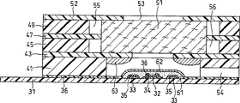
图1为本发明实施方式之一的生物传感器的分解立体图。图2为其纵截面图。FIG. 1 is an exploded perspective view of a biosensor according to one embodiment of the present invention. Figure 2 is its longitudinal section.
利用丝网印刷法在由聚对苯二甲酸乙二醇酯形成的绝缘性基板1上涂布银糊,形成导电片2、3及电极系的底层。然后,在该基板1上涂布含有树脂粘合剂的导电性碳糊形成包含工作电极4和配极5的电极系。此外,涂布绝缘性糊状物形成绝缘层6。工作电极4和配极5分别与导电片2和导电片3相连。绝缘层6覆盖部分导电片,工作电极4和配极5的露出部分面积一定。Silver paste was applied on an insulating substrate 1 made of polyethylene terephthalate by a screen printing method to form conductive sheets 2 and 3 and a bottom layer of the electrode system. Then, a conductive carbon paste containing a resin binder is coated on the substrate 1 to form an electrode system including the working electrode 4 and the counter electrode 5 . In addition, an insulating paste is applied to form the insulating layer 6 . The working electrode 4 and the counter electrode 5 are connected to the conductive sheet 2 and the conductive sheet 3 respectively. The insulating layer 6 covers part of the conductive sheet, and the exposed parts of the working electrode 4 and the matching electrode 5 have a constant area.
以上形成了电极系的绝缘性基板1、具有气孔9的罩子8、隔板7及具有血细胞过滤功能的滤膜11按照图中点划线所示的位置关系相连,形成生物传感器。基板1和罩子8间通过隔板7的缝隙10沿基板1及罩子8形成了试样溶液供给通道。滤膜11按嵌入该试样溶液供给通道的大小截断,被设置于电极系和试样供给部位,但不覆盖电极系。13a和13b分别表示滤膜11与绝缘性基板1及罩子8接触的部分。The insulating substrate 1 with the electrode system formed above, the cover 8 with the pores 9, the
滤膜11的试样供给部位12的端部到电极系的端部的区域中,为了在滤膜表面设置与形成试样溶液供给通道的基板1、隔板7及罩子8不接触的区域,在与基板1及隔板7分别对应的位置设置了透孔14及15,并在罩子8上设置了与缝隙10相连的2个凹陷部分16。为了覆盖基板1及罩子8上的透孔14及15,在它们的外面盖上了盖子17及18。由上述透孔14及15和凹陷部分16、16就形成了包围滤膜11表面的空隙部分。In the region from the end of the sample supply part 12 of the
透孔14及15分别由盖子17及18盖着,但即使不盖盖子其功能也不会受损。但是,如果不盖上盖子,则滤膜11露出在外面,所以试样溶液会从该部位蒸发,一旦液体通过滤膜到达电极系,就有可能出现液体逆流现象。因此,设置了覆盖基板及罩子上的透孔的盖子17及18。如果基板及盖子具有一定的厚度,则设置凹陷部分代替透孔,就不需要盖子17及18了。The through holes 14 and 15 are covered by covers 17 and 18 respectively, but their functions will not be impaired even if the covers are not covered. However, if the cover is not closed, the
在基板上的试样供给部位12滴下试样溶液,使该溶液与滤膜11的试样供给部位端部接触,则试样溶液被滤膜11吸收,通过滤膜11除去其中的血细胞等固形成分,将血浆导入试样溶液供给通道,再导入传感器内部。然后,血浆一边溶解位于覆盖电极的位置或其上的罩子内面的反应试剂,一边从电极系附近开始直至填满到气孔9为止的整个试样溶液供给通道。当整个试样溶液供给通道被液体填满后,滤膜11内的液体也停止流动,此时血细胞未到达滤膜的电极系端部,而是停留在原来的位置。因此,设计成从滤膜11仅通过可填满整个试样溶液供给通道的溶液量,血细胞未到达滤膜前端,血浆和血细胞间存在流通阻力差的样式。The sample solution is dripped on the sample supply part 12 on the substrate, and the solution is brought into contact with the end of the sample supply part of the
本实施例中,通过缝隙10形成的试样溶液供给通道的试样供给部位端部到气孔9的外周的长度为12.5mm,缝隙10的宽度为2.0mm,缝隙10的深度为0.1mm。In this embodiment, the length from the end of the sample supply portion of the sample solution supply channel formed by the
透孔14及15的尺寸用(与基板长度方向垂直相交的方向的长度)×(基板的长度方向尺寸)表示为4.0×3.0mm,凹陷部分16的尺寸也同样为4.0×3.0mm。基板及罩子的厚度分别为0.35mm,隔板厚度为0.1mm。因此,具有上下为0.35mm、左右为2.0mm的厚度。通过试样溶液前进方向的(以下简称为空隙部分的宽度)3.0mm的空隙部分包围滤膜11。该空隙部分位于从试样供给部位12的端部开始1mm到电极系端部3.0mm的位置。前述尺寸是较理想的实施方式的一个例子,但并不限于该尺寸。The dimensions of the through holes 14 and 15 are represented by (the length in the direction perpendicular to the longitudinal direction of the substrate)×(the longitudinal dimension of the substrate) as 4.0×3.0mm, and the dimension of the recessed
图2是生物传感器的纵截面图。基板1的电极系上形成了亲水性高分子层21及覆盖该高分子层的导电体层22。形成于隔板7的缝隙10的试样溶液供给通道中配置了滤膜11。该滤膜11的端部可以与电极系接触也可不接触,但不与电极系中的工作电极4接触。试样溶液供给通道中,在罩子8的内面由滤膜11的电极系端部和气孔9形成的区域内是酶及表面活性剂形成的层23。在层23与滤膜11的端部接触的情况下,试样溶液能够很容易地流入层23,但这种接触并不是必须的。Fig. 2 is a longitudinal sectional view of the biosensor. On the electrode system of the substrate 1, a hydrophilic polymer layer 21 and a conductor layer 22 covering the polymer layer are formed. A
图3是表示本发明另一实施方式的生物传感器中的隔板和滤膜的位置关系的平面图。形成试样溶液供给通道的缝隙10中,嵌合了滤膜的部分10a和存在电极系、并有滤膜过滤的试样溶液流过的部分10b的宽度是不同的。图3中,嵌合了滤膜的部分10a比具有电极系的部分10b窄。3 is a plan view showing the positional relationship between a separator and a filter membrane in a biosensor according to another embodiment of the present invention. In the
图4是本发明另一实施方式的生物传感器的纵截面图。虽然该传感器的结构与图2相同,但其中配置的反应试剂不同。该例子中,在电极系上仅形成了亲水性高分子层21,在罩子8一侧设置了含浸及负载了酶、表面活性剂及导电体的多孔质载体24,该载体与滤膜11的端部接触。Fig. 4 is a longitudinal sectional view of a biosensor according to another embodiment of the present invention. Although the structure of the sensor is the same as that in Figure 2, the reagents configured therein are different. In this example, only the hydrophilic polymer layer 21 is formed on the electrode system, and a porous carrier 24 impregnated and loaded with enzymes, surfactants, and conductors is provided on the cover 8 side. end contact.
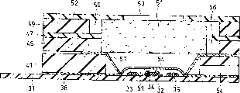
图5是本发明又一实施方式的生物传感器的纵截面图。图6是该传感器的除去了试剂层的分解立体图。Fig. 5 is a longitudinal sectional view of a biosensor according to still another embodiment of the present invention. Fig. 6 is an exploded perspective view of the sensor with the reagent layer removed.
与图1相同,在绝缘性基板31上形成了导电片32和33,以及分别与导电片相连的工作电极34及配极35、绝缘层36。该基板31上组合了多个隔板41、43、45、47、49及罩子52,在隔板43和罩子52间设置了滤膜51。罩子52的透孔53构成了试样供给部位。设置于隔板41、43、45、47、49的透孔42、44、46、48及50使试样溶液供给通道沿重力方向配置。隔板45及49的透孔46及50的孔径比滤膜51的直径大,所以在滤膜51周围形成了包围该滤膜51的空隙部分,该空隙部分用55及56表示。隔板47与滤膜51的部分外周相连,起到确定滤膜位置的作用。隔板41具有使前述试样溶液供给通道的终端朝向大气开放的气孔54。因此,从形成位于电极系上方的试样供给部位的透孔53到电极系的试样溶液供给通道通过毛细管作用使试样溶液沿重力方向导入,如果通过滤膜51过滤的血浆到达电极系,则试样溶液的流动停止。Similar to FIG. 1 ,
决定包围滤膜51的空隙部分55及56的高度的隔板49及45的厚度最好在100μm以上。隔板41的透孔42为试样溶液与试剂的反应提供了场所。隔板41的厚度最好为100~200μm。试样溶液供给通道沿重力方向配置,可使试样利用重力作用通过滤膜,然后迅速到达反应试剂层。The thickness of the
该例子中,在电极系上形成了CMC层61及导电体层62,在隔板43的内面形成了包含酶和表面活性剂的层63。In this example, a
图7是本发明另一实施方式的生物传感器的纵截面图。图8是该传感器除去了试剂层的分解立体图。所示传感器中除了用非织造布形成的试样溶液诱导层57代替隔板43之外,其他都与图5及6所示的传感器大致相同。该例子中,在电极系上设置了CMC层61及包含酶、表面活性剂和导电体的层64。Fig. 7 is a longitudinal sectional view of a biosensor according to another embodiment of the present invention. Fig. 8 is an exploded perspective view of the sensor with the reagent layer removed. The sensor shown is substantially the same as the sensor shown in FIGS. 5 and 6 except that the sample
以下,对本发明的实施例进行说明。Hereinafter, examples of the present invention will be described.
实施例1Example 1
为了制作胆甾醇传感器,首先,在图1的绝缘性基板1上的电极系上滴下亲水性高分子羧甲基纤维素的钠盐(以下称为CMC)的0.5wt%水溶液,于50℃的温风干燥器中干燥10分钟,形成CMC层21。然后,在CMC层上滴下导电体铁氰化钾的水溶液4μl(相当于铁氰化钾70mM)覆盖CMC层21,于50℃的温风干燥器中干燥10分钟后,形成铁氰化钾层22。In order to make a cholesterol sensor, first, a 0.5 wt% aqueous solution of a sodium salt of a hydrophilic polymer carboxymethylcellulose (hereinafter referred to as CMC) was dropped on the electrode system on the insulating substrate 1 of FIG. Dry in a warm air drier for 10 minutes to form a CMC layer 21. Then, on the CMC layer, 4 μl of an aqueous solution of the conductor potassium ferricyanide (corresponding to potassium ferricyanide 70 mM) was dropped to cover the CMC layer 21, and after drying for 10 minutes in a warm air drier at 50° C., a potassium ferricyanide layer was formed. twenty two.
此外,在罩子8和隔板7的缝隙10形成的凹部滴下作为表面活性剂的TritonX-100的2wt%乙醇溶液2μl,室温干燥3分钟后,形成表面活性剂层。然后,在溶解了来自奴卡氏菌的胆甾醇氧化酶(EC1.1.3.6,以下简称为ChOD)和来自假单胞菌的胆甾醇酯酶(EC.3.1.1.13,以下简称为ChE)的水溶液中添加TritonX-100。在表面活性剂层上滴下1.5μl该混合水溶液,通过液氮冷冻后,将其装入梨形烧瓶内,在冷冻干燥器中干燥一晚,形成含有1单位(U)/传感器的胆甾醇氧化酶、2.5U/传感器的胆甾醇酯酶及2wt%的表面活性剂的酶/表面活性剂层23。然后,将裁剪成2mm×8mm的长方形的玻璃薄膜(ADVANTEC公司制GC50,厚度为0.19mm)设置在图1所示位置,使其不与工作电极接触。In addition, 2 μl of a 2 wt % ethanol solution of Triton X-100 as a surfactant was dropped into the recess formed by the
如图1所示,为了在滤膜薄膜设置不与形成试样溶液供给通道的绝缘性基板、隔板及罩子接触的区域,在试样溶液供给通道的设置了滤膜的位置上设置了透孔14及15和凹陷部分16、16。它们的尺寸如前所述。As shown in Figure 1, in order to provide an area on the filter membrane that is not in contact with the insulating substrate, spacer, and cover that form the sample solution supply channel, a permeable filter is installed on the position of the sample solution supply channel where the filter membrane is installed. Holes 14 and 15 and recessed
在基板1的试样供给部位12滴下作为试样溶液的全血试样20μl。然后,通过透明材料制成的罩子8目视观察,确认从滤膜过滤的液体到达试样溶液供给通道的气孔9的外周部分开始的3分钟后,以配极为基准从正极方向对工作电极施加+0.5V的脉冲电压,测定5秒钟后的电流值。其结果是,能够获得来源于血清中的胆甾醇浓度的感应值。20 µl of a whole blood sample as a sample solution was dripped on the sample supply portion 12 of the substrate 1 . Then, through visual observation through the cover 8 made of transparent material, after confirming that the liquid filtered by the filter membrane reaches the outer peripheral portion of the air hole 9 of the sample solution supply channel for 3 minutes, apply +0.5V pulse voltage, and measure the current value after 5 seconds. As a result, a sensing value derived from the cholesterol concentration in serum can be obtained.
本实施例中,通过冷冻干燥形成了酶/表面活性剂层,也可通过风干形成该层。但是,这种情况下,由于反应试剂层的溶解性大幅度恶化,所以过滤的液体从到达试样溶液供给通道的气孔9的外周部分到反应结束需要很长时间。In this example, the enzyme/surfactant layer was formed by freeze-drying, but this layer can also be formed by air-drying. However, in this case, since the solubility of the reaction reagent layer deteriorates significantly, it takes a long time for the filtered liquid to reach the outer peripheral portion of the pores 9 of the sample solution supply channel to the end of the reaction.
实施例2Example 2
实施例1中,在试样溶液供给通道的罩子内面通过冷冻干燥形成的酶/表面活性剂层23与覆盖基板的电极系、通过风干形成的CMC层21及铁氰化钾层22一起构成了反应试剂系统。本实施例中,如图4所示,设置了含浸负载了酶、表面活性剂及导电体的多孔质载体24,该载体与滤膜11的端部接触,该载体和在覆盖基板的电极系位置通过风干的CMC层21形成反应试剂系统。In Example 1, the enzyme/surfactant layer 23 formed by freeze-drying on the inner surface of the cover of the sample solution supply channel, together with the electrode system covering the substrate, the CMC layer 21 and the potassium ferricyanide layer 22 formed by air-drying constitute a Reagent system. In the present embodiment, as shown in FIG. 4 , a porous carrier 24 impregnated with loaded enzymes, surfactants, and conductors is provided. The carrier is in contact with the end of the
多孔质载体上负载的构成反应试剂系统的部分试剂与通过冷冻干燥负载的情况相同,都能够提高反应试剂对试样溶液的溶解性。Part of the reagents constituting the reaction reagent system supported on the porous carrier can increase the solubility of the reaction reagent in the sample solution, as in the case of loading by freeze-drying.
首先,与实施例1同样在电极系上滴下亲水性高分子CMC的0.5wt%水溶液,于50℃的温风干燥器中干燥10分钟,形成CMC层21。First, like in Example 1, a 0.5 wt % aqueous solution of hydrophilic polymer CMC was dropped onto the electrode system, and dried in a warm air drier at 50° C. for 10 minutes to form the CMC layer 21 .
然后,用纤维系粘合剂(塞梅代恩公司制塞梅代恩C)使裁剪成2×4.5mm的以玻璃纤维为主成分的毛毡形成的多孔质载体24与滤膜11的端部接触,将其粘合固定在图4所示的试样溶液供给通道的罩子侧的位置。Then, the end portion of the porous carrier 24 formed by the felt mainly composed of glass fibers cut into 2×4.5 mm and the end of the
与实施例1相同,在该多孔质载体24上滴下溶解了胆甾醇氧化酶、胆甾醇酯酶、铁氰化钾及TritonX-100的水5μl,均匀渗透后,于50℃的温风干燥器干燥15分钟。Same as in Example 1, 5 μl of water in which cholesterol oxidase, cholesterol esterase, potassium ferricyanide and TritonX-100 were dissolved was dripped on the porous carrier 24, and after uniform penetration, the solution was dried in a warm air dryer at 50°C. Let dry for 15 minutes.
然后,与实施例1同样,配置滤膜11,粘合前述罩子部件和基板1,制成生物传感器。但是,由于多孔质载体24的厚度约为0.1~0.2mm,所以,与试样溶液供给通道的滤膜11相比,电极系中的基板1和罩子8间的距离比实施例1的0.1mm大,为0.3mm。因此,实施例2所用的滤膜11为GB100R。Then, in the same manner as in Example 1, the
在试样供给部位滴下全血试样3分钟后,上述生物传感器可显示出来源于胆甾醇浓度的感应值。Three minutes after the whole blood sample was dropped on the sample supply site, the above-mentioned biosensor can display a sensing value derived from the concentration of cholesterol.
以上实施例中,基板1及罩子8都是用透明材料制成的,这样能够通过目视确认试样的流动情况。In the above embodiments, both the substrate 1 and the cover 8 are made of transparent materials, so that the flow of the sample can be confirmed visually.
以上实施例中,形成试样溶液供给通道的缝隙10的有滤膜嵌合的部分和存在电极系、有从滤膜过滤的试样流入的部分的宽度是相同的,但任何一部分都可以采用较狭小的形状。如此的例子中的隔板及滤膜的位置关系及形状如图5所示。In the above embodiments, the width of the part where the filter membrane is fitted in the
只要构成反应试剂系统的试剂的配置及负载方法能够使构成反应试剂系统的试剂能够迅速溶入试样溶液,使酶反应顺利进行即可,并不仅限于本实施例的条件。As long as the configuration and loading method of the reagents constituting the reaction reagent system can quickly dissolve the reagents constituting the reaction reagent system into the sample solution and make the enzyme reaction proceed smoothly, it is not limited to the conditions of this embodiment.
产业上利用的可能性Possibility of industrial use
如上所述,本发明通过防止含有血细胞等固形成分的试样溶液中的固形成分与电极系或反应试剂系统接触,提供了测定精度和感应值的稳定性都有所提高的生物传感器。As described above, the present invention provides a biosensor with improved measurement accuracy and sensing value stability by preventing solid components in a sample solution containing solid components such as blood cells from contacting an electrode system or a reaction reagent system.
Claims (14)
Translated fromChineseApplications Claiming Priority (3)
| Application Number | Priority Date | Filing Date | Title |
|---|---|---|---|
| JP2000232385 | 2000-07-31 | ||
| JP232385/2000 | 2000-07-31 | ||
| JP232385/00 | 2000-07-31 |
Publications (2)
| Publication Number | Publication Date |
|---|---|
| CN1386194A CN1386194A (en) | 2002-12-18 |
| CN1180259Ctrue CN1180259C (en) | 2004-12-15 |
Family
ID=18725079
Family Applications (1)
| Application Number | Title | Priority Date | Filing Date |
|---|---|---|---|
| CNB018022340AExpired - Fee RelatedCN1180259C (en) | 2000-07-31 | 2001-07-26 | biological sensor |
Country Status (7)
| Country | Link |
|---|---|
| US (1) | US6776888B2 (en) |
| EP (1) | EP1223425B1 (en) |
| JP (1) | JP4184074B2 (en) |
| CN (1) | CN1180259C (en) |
| DE (1) | DE60137111D1 (en) |
| ES (1) | ES2317947T3 (en) |
| WO (1) | WO2002010735A1 (en) |
Cited By (1)
| Publication number | Priority date | Publication date | Assignee | Title |
|---|---|---|---|---|
| CN107917942A (en)* | 2016-10-11 | 2018-04-17 | 广州好芝生物科技有限公司 | A kind of electrode system and strip and instrument containing the electrode system |
Families Citing this family (122)
| Publication number | Priority date | Publication date | Assignee | Title |
|---|---|---|---|---|
| US6036924A (en) | 1997-12-04 | 2000-03-14 | Hewlett-Packard Company | Cassette of lancet cartridges for sampling blood |
| US8071384B2 (en) | 1997-12-22 | 2011-12-06 | Roche Diagnostics Operations, Inc. | Control and calibration solutions and methods for their use |
| US6391005B1 (en) | 1998-03-30 | 2002-05-21 | Agilent Technologies, Inc. | Apparatus and method for penetration with shaft having a sensor for sensing penetration depth |
| US20050103624A1 (en) | 1999-10-04 | 2005-05-19 | Bhullar Raghbir S. | Biosensor and method of making |
| US6645359B1 (en)* | 2000-10-06 | 2003-11-11 | Roche Diagnostics Corporation | Biosensor |
| US8641644B2 (en) | 2000-11-21 | 2014-02-04 | Sanofi-Aventis Deutschland Gmbh | Blood testing apparatus having a rotatable cartridge with multiple lancing elements and testing means |
| JP4209767B2 (en) | 2001-06-12 | 2009-01-14 | ペリカン テクノロジーズ インコーポレイテッド | Self-optimized cutting instrument with adaptive means for temporary changes in skin properties |
| US9795747B2 (en) | 2010-06-02 | 2017-10-24 | Sanofi-Aventis Deutschland Gmbh | Methods and apparatus for lancet actuation |
| US7344507B2 (en) | 2002-04-19 | 2008-03-18 | Pelikan Technologies, Inc. | Method and apparatus for lancet actuation |
| US9226699B2 (en) | 2002-04-19 | 2016-01-05 | Sanofi-Aventis Deutschland Gmbh | Body fluid sampling module with a continuous compression tissue interface surface |
| JP4272051B2 (en) | 2001-06-12 | 2009-06-03 | ペリカン テクノロジーズ インコーポレイテッド | Blood sampling apparatus and method |
| AU2002344825A1 (en) | 2001-06-12 | 2002-12-23 | Pelikan Technologies, Inc. | Method and apparatus for improving success rate of blood yield from a fingerstick |
| US7981056B2 (en) | 2002-04-19 | 2011-07-19 | Pelikan Technologies, Inc. | Methods and apparatus for lancet actuation |
| US7041068B2 (en) | 2001-06-12 | 2006-05-09 | Pelikan Technologies, Inc. | Sampling module device and method |
| US7749174B2 (en) | 2001-06-12 | 2010-07-06 | Pelikan Technologies, Inc. | Method and apparatus for lancet launching device intergrated onto a blood-sampling cartridge |
| EP1395185B1 (en) | 2001-06-12 | 2010-10-27 | Pelikan Technologies Inc. | Electric lancet actuator |
| WO2002101359A2 (en) | 2001-06-12 | 2002-12-19 | Pelikan Technologies, Inc. | Integrated blood sampling analysis system with multi-use sampling module |
| US9427532B2 (en) | 2001-06-12 | 2016-08-30 | Sanofi-Aventis Deutschland Gmbh | Tissue penetration device |
| US8337419B2 (en) | 2002-04-19 | 2012-12-25 | Sanofi-Aventis Deutschland Gmbh | Tissue penetration device |
| US7344894B2 (en) | 2001-10-16 | 2008-03-18 | Agilent Technologies, Inc. | Thermal regulation of fluidic samples within a diagnostic cartridge |
| JPWO2003042680A1 (en)* | 2001-11-14 | 2005-03-10 | 松下電器産業株式会社 | Biosensor |
| CN1498344A (en)* | 2001-11-14 | 2004-05-19 | 松下电器产业株式会社 | Biosensor and method for measuring the same |
| DE60222809T2 (en)* | 2002-03-01 | 2008-06-26 | Matsushita Electric Industrial Co., Ltd., Kadoma | BIOSENSOR |
| US8221334B2 (en) | 2002-04-19 | 2012-07-17 | Sanofi-Aventis Deutschland Gmbh | Method and apparatus for penetrating tissue |
| US8784335B2 (en) | 2002-04-19 | 2014-07-22 | Sanofi-Aventis Deutschland Gmbh | Body fluid sampling device with a capacitive sensor |
| US8267870B2 (en) | 2002-04-19 | 2012-09-18 | Sanofi-Aventis Deutschland Gmbh | Method and apparatus for body fluid sampling with hybrid actuation |
| US8360992B2 (en) | 2002-04-19 | 2013-01-29 | Sanofi-Aventis Deutschland Gmbh | Method and apparatus for penetrating tissue |
| US7485128B2 (en) | 2002-04-19 | 2009-02-03 | Pelikan Technologies, Inc. | Method and apparatus for penetrating tissue |
| WO2003088824A2 (en) | 2002-04-19 | 2003-10-30 | Pelikan Technologies, Inc. | Device and method for variable speed lancet |
| US7976476B2 (en) | 2002-04-19 | 2011-07-12 | Pelikan Technologies, Inc. | Device and method for variable speed lancet |
| US7491178B2 (en) | 2002-04-19 | 2009-02-17 | Pelikan Technologies, Inc. | Method and apparatus for penetrating tissue |
| US7524293B2 (en) | 2002-04-19 | 2009-04-28 | Pelikan Technologies, Inc. | Method and apparatus for penetrating tissue |
| US7563232B2 (en) | 2002-04-19 | 2009-07-21 | Pelikan Technologies, Inc. | Method and apparatus for penetrating tissue |
| US7648468B2 (en) | 2002-04-19 | 2010-01-19 | Pelikon Technologies, Inc. | Method and apparatus for penetrating tissue |
| US7371247B2 (en) | 2002-04-19 | 2008-05-13 | Pelikan Technologies, Inc | Method and apparatus for penetrating tissue |
| US8372016B2 (en) | 2002-04-19 | 2013-02-12 | Sanofi-Aventis Deutschland Gmbh | Method and apparatus for body fluid sampling and analyte sensing |
| US7331931B2 (en) | 2002-04-19 | 2008-02-19 | Pelikan Technologies, Inc. | Method and apparatus for penetrating tissue |
| US7244265B2 (en) | 2002-04-19 | 2007-07-17 | Pelikan Technologies, Inc. | Method and apparatus for penetrating tissue |
| US7229458B2 (en) | 2002-04-19 | 2007-06-12 | Pelikan Technologies, Inc. | Method and apparatus for penetrating tissue |
| US7717863B2 (en) | 2002-04-19 | 2010-05-18 | Pelikan Technologies, Inc. | Method and apparatus for penetrating tissue |
| US7232451B2 (en) | 2002-04-19 | 2007-06-19 | Pelikan Technologies, Inc. | Method and apparatus for penetrating tissue |
| US7297122B2 (en) | 2002-04-19 | 2007-11-20 | Pelikan Technologies, Inc. | Method and apparatus for penetrating tissue |
| US7582099B2 (en) | 2002-04-19 | 2009-09-01 | Pelikan Technologies, Inc | Method and apparatus for penetrating tissue |
| US9314194B2 (en) | 2002-04-19 | 2016-04-19 | Sanofi-Aventis Deutschland Gmbh | Tissue penetration device |
| US9795334B2 (en) | 2002-04-19 | 2017-10-24 | Sanofi-Aventis Deutschland Gmbh | Method and apparatus for penetrating tissue |
| US9248267B2 (en) | 2002-04-19 | 2016-02-02 | Sanofi-Aventis Deustchland Gmbh | Tissue penetration device |
| US7674232B2 (en) | 2002-04-19 | 2010-03-09 | Pelikan Technologies, Inc. | Method and apparatus for penetrating tissue |
| US8579831B2 (en) | 2002-04-19 | 2013-11-12 | Sanofi-Aventis Deutschland Gmbh | Method and apparatus for penetrating tissue |
| US7901362B2 (en) | 2002-04-19 | 2011-03-08 | Pelikan Technologies, Inc. | Method and apparatus for penetrating tissue |
| US7410468B2 (en) | 2002-04-19 | 2008-08-12 | Pelikan Technologies, Inc. | Method and apparatus for penetrating tissue |
| US7374544B2 (en) | 2002-04-19 | 2008-05-20 | Pelikan Technologies, Inc. | Method and apparatus for penetrating tissue |
| US7892183B2 (en) | 2002-04-19 | 2011-02-22 | Pelikan Technologies, Inc. | Method and apparatus for body fluid sampling and analyte sensing |
| US7141058B2 (en) | 2002-04-19 | 2006-11-28 | Pelikan Technologies, Inc. | Method and apparatus for a body fluid sampling device using illumination |
| US7708701B2 (en) | 2002-04-19 | 2010-05-04 | Pelikan Technologies, Inc. | Method and apparatus for a multi-use body fluid sampling device |
| US7547287B2 (en) | 2002-04-19 | 2009-06-16 | Pelikan Technologies, Inc. | Method and apparatus for penetrating tissue |
| US7909778B2 (en) | 2002-04-19 | 2011-03-22 | Pelikan Technologies, Inc. | Method and apparatus for penetrating tissue |
| US8702624B2 (en) | 2006-09-29 | 2014-04-22 | Sanofi-Aventis Deutschland Gmbh | Analyte measurement device with a single shot actuator |
| US7291117B2 (en) | 2002-04-19 | 2007-11-06 | Pelikan Technologies, Inc. | Method and apparatus for penetrating tissue |
| CN1467496A (en)* | 2002-06-03 | 2004-01-14 | 松下电器产业株式会社 | biological sensor |
| JP3878993B2 (en)* | 2002-10-31 | 2007-02-07 | アークレイ株式会社 | Analysis tool |
| EP1557663B1 (en)* | 2002-11-01 | 2007-08-01 | ARKRAY, Inc. | Measuring instrument provided with sold component concentrating means |
| US8574895B2 (en) | 2002-12-30 | 2013-11-05 | Sanofi-Aventis Deutschland Gmbh | Method and apparatus using optical techniques to measure analyte levels |
| CN1701229A (en)* | 2003-04-28 | 2005-11-23 | 松下电器产业株式会社 | Filter and biosensor with the same |
| JP4208879B2 (en)* | 2003-05-15 | 2009-01-14 | パナソニック株式会社 | Sensor |
| US8153081B2 (en) | 2003-05-29 | 2012-04-10 | Bayer Healthcare Llc | Test sensor and method for manufacturing the same |
| DE602004028463D1 (en) | 2003-05-30 | 2010-09-16 | Pelikan Technologies Inc | METHOD AND DEVICE FOR INJECTING LIQUID |
| US7850621B2 (en) | 2003-06-06 | 2010-12-14 | Pelikan Technologies, Inc. | Method and apparatus for body fluid sampling and analyte sensing |
| KR100554649B1 (en)* | 2003-06-09 | 2006-02-24 | 주식회사 아이센스 | Electrochemical Biosensor |
| WO2006001797A1 (en) | 2004-06-14 | 2006-01-05 | Pelikan Technologies, Inc. | Low pain penetrating |
| EP1635700B1 (en) | 2003-06-13 | 2016-03-09 | Sanofi-Aventis Deutschland GmbH | Apparatus for a point of care device |
| US8148164B2 (en) | 2003-06-20 | 2012-04-03 | Roche Diagnostics Operations, Inc. | System and method for determining the concentration of an analyte in a sample fluid |
| US8206565B2 (en) | 2003-06-20 | 2012-06-26 | Roche Diagnostics Operation, Inc. | System and method for coding information on a biosensor test strip |
| US7645373B2 (en) | 2003-06-20 | 2010-01-12 | Roche Diagnostic Operations, Inc. | System and method for coding information on a biosensor test strip |
| US7597793B2 (en) | 2003-06-20 | 2009-10-06 | Roche Operations Ltd. | System and method for analyte measurement employing maximum dosing time delay |
| US7452457B2 (en) | 2003-06-20 | 2008-11-18 | Roche Diagnostics Operations, Inc. | System and method for analyte measurement using dose sufficiency electrodes |
| US7645421B2 (en) | 2003-06-20 | 2010-01-12 | Roche Diagnostics Operations, Inc. | System and method for coding information on a biosensor test strip |
| US8679853B2 (en) | 2003-06-20 | 2014-03-25 | Roche Diagnostics Operations, Inc. | Biosensor with laser-sealed capillary space and method of making |
| JP4447009B2 (en) | 2003-06-20 | 2010-04-07 | エフ ホフマン−ラ ロッシュ アクチェン ゲゼルシャフト | Test strip with slot vent opening |
| US8071030B2 (en) | 2003-06-20 | 2011-12-06 | Roche Diagnostics Operations, Inc. | Test strip with flared sample receiving chamber |
| US8058077B2 (en) | 2003-06-20 | 2011-11-15 | Roche Diagnostics Operations, Inc. | Method for coding information on a biosensor test strip |
| US7604721B2 (en) | 2003-06-20 | 2009-10-20 | Roche Diagnostics Operations, Inc. | System and method for coding information on a biosensor test strip |
| US7718439B2 (en) | 2003-06-20 | 2010-05-18 | Roche Diagnostics Operations, Inc. | System and method for coding information on a biosensor test strip |
| US8282576B2 (en) | 2003-09-29 | 2012-10-09 | Sanofi-Aventis Deutschland Gmbh | Method and apparatus for an improved sample capture device |
| EP1680014A4 (en) | 2003-10-14 | 2009-01-21 | Pelikan Technologies Inc | METHOD AND DEVICE FOR A VARIABLE USER INTERFACE |
| US8668656B2 (en) | 2003-12-31 | 2014-03-11 | Sanofi-Aventis Deutschland Gmbh | Method and apparatus for improving fluidic flow and sample capture |
| US7822454B1 (en) | 2005-01-03 | 2010-10-26 | Pelikan Technologies, Inc. | Fluid sampling device with improved analyte detecting member configuration |
| US7622026B2 (en)* | 2004-03-02 | 2009-11-24 | Panasonic Corporation | Biosensor |
| WO2006011062A2 (en) | 2004-05-20 | 2006-02-02 | Albatros Technologies Gmbh & Co. Kg | Printable hydrogel for biosensors |
| WO2005120365A1 (en) | 2004-06-03 | 2005-12-22 | Pelikan Technologies, Inc. | Method and apparatus for a fluid sampling device |
| US9775553B2 (en) | 2004-06-03 | 2017-10-03 | Sanofi-Aventis Deutschland Gmbh | Method and apparatus for a fluid sampling device |
| US7569126B2 (en) | 2004-06-18 | 2009-08-04 | Roche Diagnostics Operations, Inc. | System and method for quality assurance of a biosensor test strip |
| US7556723B2 (en) | 2004-06-18 | 2009-07-07 | Roche Diagnostics Operations, Inc. | Electrode design for biosensor |
| US8652831B2 (en) | 2004-12-30 | 2014-02-18 | Sanofi-Aventis Deutschland Gmbh | Method and apparatus for analyte measurement test time |
| US20090053105A1 (en)* | 2005-01-24 | 2009-02-26 | Toshifumi Hosoya | Sensor Chip |
| CA2595802A1 (en)* | 2005-01-24 | 2006-07-27 | Sumitomo Electric Industries, Ltd. | Sensor chip |
| JP2006201112A (en)* | 2005-01-24 | 2006-08-03 | Sumitomo Electric Ind Ltd | Sensor chip |
| DE602007000964D1 (en)* | 2007-02-28 | 2009-06-04 | Gen Life Biotechnology Co Ltd | Measuring element for the detection of total cholesterol in a blood sample |
| KR100885074B1 (en)* | 2007-07-26 | 2009-02-25 | 주식회사 아이센스 | Microfluidic Sensor Complex Structure |
| USD588477S1 (en)* | 2007-12-31 | 2009-03-17 | Nihon Dempa Kogyo Co., Ltd. | Bio-sensor |
| EP2265324B1 (en) | 2008-04-11 | 2015-01-28 | Sanofi-Aventis Deutschland GmbH | Integrated analyte measurement system |
| USD603725S1 (en)* | 2008-09-09 | 2009-11-10 | Nihon Dempa Kogyo Co., Ltd. | Bio-sensor |
| USD604185S1 (en)* | 2008-09-09 | 2009-11-17 | Nihon Dempa Kogyo Co., Ltd. | Bio-sensor |
| USD605535S1 (en)* | 2008-09-09 | 2009-12-08 | Nihon Dempa Kogyo Co., Ltd. | Bio-sensor |
| KR101179555B1 (en) | 2008-12-22 | 2012-09-05 | 한국전자통신연구원 | Bio-sensor chip |
| US9375169B2 (en) | 2009-01-30 | 2016-06-28 | Sanofi-Aventis Deutschland Gmbh | Cam drive for managing disposable penetrating member actions with a single motor and motor and control system |
| TWM359696U (en)* | 2009-02-13 | 2009-06-21 | Apex Biotechnology Corp | Biochemical test system, measurement device, and biochemical test strip |
| KR101032691B1 (en)* | 2009-04-17 | 2011-05-06 | (주)디지탈옵틱 | Biosensor for diagnosis of disease that can rapidly separate blood cells |
| US8965476B2 (en) | 2010-04-16 | 2015-02-24 | Sanofi-Aventis Deutschland Gmbh | Tissue penetration device |
| WO2013105678A1 (en)* | 2012-01-11 | 2013-07-18 | 경원대학교 산학협력단 | Blood glucose measurement unit, blood glucose measurement system comprising same, and blood glucose measurement method |
| WO2014027225A1 (en)* | 2012-08-13 | 2014-02-20 | Achira Labs Pvt. Ltd. | Compositions for fabric based lateral flow assay device using electrochemical detection means, and devices therefrom |
| CN103630593A (en)* | 2012-08-21 | 2014-03-12 | 苏州宇钿医疗器械有限公司 | Two-electrode glucolase electrode sensor |
| US9188561B2 (en)* | 2013-03-03 | 2015-11-17 | Yue Xu | Test strip |
| KR20150009745A (en)* | 2013-07-17 | 2015-01-27 | 주식회사 미코 | Bio sensor chip |
| US20180164243A1 (en)* | 2015-06-05 | 2018-06-14 | Nitto Denko Corporation | Biosensor chip and biosensor device |
| CN111343919B (en)* | 2017-11-21 | 2023-10-10 | Bbb有限公司 | biological sensor |
| EP3751266A4 (en)* | 2018-02-09 | 2022-02-09 | Hamamatsu Photonics K.K. | SPECIMEN |
| US20210113145A1 (en)* | 2018-04-19 | 2021-04-22 | The Regents Of The University Of California | Low cost, transferrable and thermally stable sensor array patterned on conductive substrate for biofluid analysis |
| JP7056863B2 (en)* | 2018-04-25 | 2022-04-19 | ビービービー インコーポレイテッド | Blood analyzer |
| JP7243994B2 (en)* | 2018-04-25 | 2023-03-22 | ビービービー インコーポレイテッド | hematology analyzer |
| EP3951374A1 (en)* | 2020-08-03 | 2022-02-09 | Consejo Superior de Investigaciones Científicas (CSIC) | Biosensor system for multiplexed detection of biomarkers |
| CN112748167B (en)* | 2020-10-27 | 2022-04-26 | 浙江大学 | A kind of needle-shaped all-solid-state sensor for dopamine detection and preparation method thereof |
| KR102781046B1 (en)* | 2020-12-02 | 2025-03-14 | 동우 화인켐 주식회사 | Patch type biosensor |
Family Cites Families (15)
| Publication number | Priority date | Publication date | Assignee | Title |
|---|---|---|---|---|
| US3607092A (en)* | 1970-03-23 | 1971-09-21 | Ibm | Automatic fluid sample apparatus |
| DE3029579C2 (en)* | 1980-08-05 | 1985-12-12 | Boehringer Mannheim Gmbh, 6800 Mannheim | Method and means for separating plasma or serum from whole blood |
| JPH0654304B2 (en) | 1986-08-28 | 1994-07-20 | 松下電器産業株式会社 | Biosensor |
| JPH01134246A (en) | 1987-11-19 | 1989-05-26 | Matsushita Electric Ind Co Ltd | Biosensor |
| JP2502666B2 (en) | 1988-01-29 | 1996-05-29 | 松下電器産業株式会社 | Biosensor and manufacturing method thereof |
| GB9309797D0 (en)* | 1993-05-12 | 1993-06-23 | Medisense Inc | Electrochemical sensors |
| ES2148272T3 (en)* | 1993-12-29 | 2000-10-16 | Mochida Pharm Co Ltd | ELECTROCHEMICAL TEST METHOD AND COMPOSITE OF NEW P-PHENYLENDIAMINE. |
| US5522977A (en)* | 1994-10-07 | 1996-06-04 | Biomedix, Inc. | Glucose sensor |
| US5779867A (en)* | 1994-10-07 | 1998-07-14 | Biomedix, Inc. | Dry chemistry glucose sensor |
| US5962215A (en) | 1996-04-05 | 1999-10-05 | Mercury Diagnostics, Inc. | Methods for testing the concentration of an analyte in a body fluid |
| JP3745452B2 (en)* | 1996-05-30 | 2006-02-15 | 松下電器産業株式会社 | Biosensor and manufacturing method thereof |
| JP3487396B2 (en) | 1997-01-31 | 2004-01-19 | 松下電器産業株式会社 | Biosensor and manufacturing method thereof |
| JP4621839B2 (en) | 1999-11-15 | 2011-01-26 | アークレイ株式会社 | Biosensor |
| JP2001201479A (en) | 2000-01-21 | 2001-07-27 | Matsushita Electric Ind Co Ltd | Biosensor |
| US6726818B2 (en) | 2000-07-21 | 2004-04-27 | I-Sens, Inc. | Biosensors with porous chromatographic membranes |
- 2001
- 2001-07-26CNCNB018022340Apatent/CN1180259C/ennot_activeExpired - Fee Related
- 2001-07-26DEDE60137111Tpatent/DE60137111D1/ennot_activeExpired - Lifetime
- 2001-07-26JPJP2002516612Apatent/JP4184074B2/ennot_activeExpired - Fee Related
- 2001-07-26EPEP01984441Apatent/EP1223425B1/ennot_activeExpired - Lifetime
- 2001-07-26ESES01984441Tpatent/ES2317947T3/ennot_activeExpired - Lifetime
- 2001-07-26WOPCT/JP2001/006472patent/WO2002010735A1/ennot_activeCeased
- 2001-07-26USUS10/089,289patent/US6776888B2/ennot_activeExpired - Fee Related
Cited By (1)
| Publication number | Priority date | Publication date | Assignee | Title |
|---|---|---|---|---|
| CN107917942A (en)* | 2016-10-11 | 2018-04-17 | 广州好芝生物科技有限公司 | A kind of electrode system and strip and instrument containing the electrode system |
Also Published As
| Publication number | Publication date |
|---|---|
| ES2317947T3 (en) | 2009-05-01 |
| EP1223425B1 (en) | 2008-12-24 |
| CN1386194A (en) | 2002-12-18 |
| EP1223425A4 (en) | 2003-06-04 |
| EP1223425A1 (en) | 2002-07-17 |
| US6776888B2 (en) | 2004-08-17 |
| US20020148726A1 (en) | 2002-10-17 |
| WO2002010735A1 (en) | 2002-02-07 |
| DE60137111D1 (en) | 2009-02-05 |
| JP4184074B2 (en) | 2008-11-19 |
Similar Documents
| Publication | Publication Date | Title |
|---|---|---|
| CN1180259C (en) | biological sensor | |
| CN1207563C (en) | Biosensor | |
| CN1309294A (en) | Biologic sensor | |
| CN1193229C (en) | Biosensor | |
| CN1201147C (en) | biological sensor | |
| CN1122178C (en) | Substrate determining method | |
| CN1241012C (en) | Disposable test strips with integrated reagent/blood separation layer | |
| US6627057B1 (en) | Microsphere containing sensor | |
| CN1205474C (en) | biological sensor | |
| CN100523800C (en) | sensor | |
| CN100339701C (en) | Biosensor | |
| CN1301962A (en) | Biological sensor | |
| CN1301963A (en) | Biological sensor | |
| CN1498344A (en) | Biosensor and method for measuring the same | |
| CN1763518A (en) | Electrochemical battery | |
| CN1573324A (en) | Electrochemical biosensor | |
| CN1334460A (en) | Biological sensor with porous chromatograph diaphragm | |
| CN1514937A (en) | Electrochemical Biosensor | |
| CN1189612A (en) | Cholesterol sensor and manufacturing method thereof | |
| US6471839B1 (en) | Biosensor | |
| CN1312469A (en) | Biological sensor and producing method | |
| CN1349096A (en) | Electrochemical electrode test piece and manufacturing method thereof | |
| JP2003065997A (en) | Biosensor | |
| JP2003254934A (en) | Biosensor | |
| JP2001201480A (en) | Biosensor |
Legal Events
| Date | Code | Title | Description |
|---|---|---|---|
| C06 | Publication | ||
| PB01 | Publication | ||
| C10 | Entry into substantive examination | ||
| SE01 | Entry into force of request for substantive examination | ||
| C14 | Grant of patent or utility model | ||
| GR01 | Patent grant | ||
| ASS | Succession or assignment of patent right | Owner name:PANASONIC HEALTHCARE + MEDICAL EQUIPMENT CO., LTD. Free format text:FORMER OWNER: MATSUSHITA ELECTRIC INDUSTRIAL CO, LTD. Effective date:20140514 | |
| C41 | Transfer of patent application or patent right or utility model | ||
| TR01 | Transfer of patent right | Effective date of registration:20140514 Address after:Ehime Prefecture, Japan Patentee after:Panasonic Healthcare Co., Ltd Address before:Japan Osaka Patentee before:Matsushita Electric Industrial Co., Ltd. | |
| CF01 | Termination of patent right due to non-payment of annual fee | Granted publication date:20041215 Termination date:20140726 | |
| EXPY | Termination of patent right or utility model |