CN1164904A - Apparatus and method for real-time volume visualization - Google Patents
Apparatus and method for real-time volume visualizationDownload PDFInfo
- Publication number
- CN1164904A CN1164904ACN95195972ACN95195972ACN1164904ACN 1164904 ACN1164904 ACN 1164904ACN 95195972 ACN95195972 ACN 95195972ACN 95195972 ACN95195972 ACN 95195972ACN 1164904 ACN1164904 ACN 1164904A
- Authority
- CN
- China
- Prior art keywords
- dimensional
- voxel
- signal
- generating
- sample
- Prior art date
- Legal status (The legal status is an assumption and is not a legal conclusion. Google has not performed a legal analysis and makes no representation as to the accuracy of the status listed.)
- Pending
Links
Images


Classifications
- G—PHYSICS
- G06—COMPUTING OR CALCULATING; COUNTING
- G06T—IMAGE DATA PROCESSING OR GENERATION, IN GENERAL
- G06T1/00—General purpose image data processing
- G06T1/20—Processor architectures; Processor configuration, e.g. pipelining
- G—PHYSICS
- G06—COMPUTING OR CALCULATING; COUNTING
- G06T—IMAGE DATA PROCESSING OR GENERATION, IN GENERAL
- G06T15/00—3D [Three Dimensional] image rendering
- G06T15/005—General purpose rendering architectures
- G—PHYSICS
- G06—COMPUTING OR CALCULATING; COUNTING
- G06T—IMAGE DATA PROCESSING OR GENERATION, IN GENERAL
- G06T15/00—3D [Three Dimensional] image rendering
- G06T15/08—Volume rendering
- G—PHYSICS
- G06—COMPUTING OR CALCULATING; COUNTING
- G06T—IMAGE DATA PROCESSING OR GENERATION, IN GENERAL
- G06T15/00—3D [Three Dimensional] image rendering
- G06T15/10—Geometric effects
Landscapes
- Engineering & Computer Science (AREA)
- Physics & Mathematics (AREA)
- General Physics & Mathematics (AREA)
- Theoretical Computer Science (AREA)
- Computer Graphics (AREA)
- Geometry (AREA)
- Image Generation (AREA)
- Image Processing (AREA)
- Apparatus For Radiation Diagnosis (AREA)
- Measurement Of Velocity Or Position Using Acoustic Or Ultrasonic Waves (AREA)
- Measuring And Recording Apparatus For Diagnosis (AREA)
- Ultra Sonic Daignosis Equipment (AREA)
- Image Analysis (AREA)
- Analysing Materials By The Use Of Radiation (AREA)
Abstract
Translated fromChinese
Description
Translated fromChinese发明的背景background of the invention
本发明涉及三维(3-D)图形学与立体成象,更具体地涉及高清晰度立体图象的实时平行与透视投影的装置与方法。The present invention relates to three-dimensional (3-D) graphics and stereoscopic imaging, and more particularly to a device and method for real-time parallel and perspective projection of high-definition stereoscopic images.
图象描绘是将复杂信息转换成能改善人类理解同时保持信息的完整性与精确性的格式的过程。由涉及三维现象的信息所组成的立体数据是一种能从改良的图象描绘技术中得益的复杂信息。分析立体数据来确定从一个给定的视点要显示立体的哪些部分的过程通常称作立体显象。传统立体显象方法以顺序方式扫描数据点进行操作以便提供对象的精确表示。需要实时塑造对象及利用计算机图象系统来这样做的优点是显而易见的。Image rendering is the process of converting complex information into a format that improves human understanding while maintaining the integrity and accuracy of the information. Volumetric data consisting of information relating to three-dimensional phenomena is a complex type of information that could benefit from improved image rendering techniques. The process of analyzing stereo data to determine which parts of the volume to display from a given viewpoint is commonly referred to as stereoscopic imaging. Traditional stereoscopic visualization methods operate by scanning data points in a sequential fashion in order to provide an accurate representation of the object. The need to shape objects in real time and the advantages of using a computer graphics system to do so are obvious.
立体显象的专用计算机体系结构与方法是已知的。参见图1,已知有一种立体显象系统1。该立体显象系统1包括:一个立体帧缓冲器2,它带有斜移存储器组织,该存储器组织能在任何正交方向上进行三维象素束的无冲突访问;一个二维(2~D)斜移缓冲器4;一个射线投影树6;以及,两个传送器8、10。传送器通常称作桶形移位器。第一传送器8连在立方帧缓冲器与二维斜移缓冲器之间,而第二传送器10则连在二维斜移缓冲器与射线投影树之间。这种立体显象系统能在0(n2logn)时间内提供平行投影,其中n为立方帧缓冲器的一条轴的测度。Special purpose computer architectures and methods for stereoscopic visualization are known. Referring to Fig. 1, a
立方帧缓冲器2与2-D斜移缓冲器的操作与相互关系示出在图2中。传统的立体显象系统1通过将发源在投影平面(未示出)上的一个象素上的视线沿选择的观察方向投射过立方帧缓冲器2而进行操作。视线访问存储在立方帧缓冲器中的多个三维象素14(限定了一个投影射线平面(PRP)16)。限定PRP的三维象素同时被正交束18检索并提供给传送器8。The operation and interrelationships of the
传送器8提供限定PRP的正交束的三维象素的2-D剪切。这一2-D剪切的作用是使各离散观察视线的所有三维象素沿平行于2-D斜交缓冲器的2-D轴的方向与所提供的斜交视线相对准。一旦这些视线在2-D斜移缓冲器中对准,便能由射线投影树6检索与处理这些斜交视线了。Conveyor 8 provides 2-D cropping of voxels defining orthogonal beams of PRP. The effect of this 2-D clipping is to align all voxels of each discrete view view line with the provided skew line of sight in a direction parallel to the 2-D axis of the 2-D skew buffer. Once these views are aligned in the 2-D skew buffer, the oblique views can be retrieved and processed by the ray projection tree 6 .
在射线投影树6接收这些斜交视线之前,将所访问到的斜交视线提供给传送器10。为了使射线投影树6的输入模块的物理顺序次序与各视线的三维象素的顺序次序相匹配,传送器10执行去斜移操作。具体地说,将各视线移位使得各投影射线的第一个三维象素出现在射线投影树的相应的第一输入位置上。然后,射线投影树并行处理各射线的三维象素以便生成一个与该投影射线相关联的象素值。The accessed oblique sight lines are provided to the transmitter 10 before the ray projection tree 6 receives them. In order to match the physical sequential order of the input modules of the ray projection tree 6 with the sequential order of the voxels of each view, the transmitter 10 performs a deskew operation. Specifically, each line of sight is shifted such that the first voxel of each projected ray occurs at the corresponding first input position of the ray projection tree. The ray projection tree then processes the voxels for each ray in parallel to generate a pixel value associated with the projected ray.
上面公开的立体显象系统具有实质性缺点和缺陷。首先,系统的操作速度受到可提供0(n2logn)时间的任意平行与正交投影的系统体系结构的限制。第二,射线投影树要求沿特定的朝向将各投影射线提供给它。这在二维斜移缓冲器与射线投影树之间需要有一个传送器,这便增加了系统需要的总体硬件及立体显象所需的时间。第三,传统的系统通过利用最近的不透明离散三维象素只对沿该离散投影射线的点提供离散投影射线的表面近似值而不是沿连续投影射线的实际值。这就会提供对象的某些不精确表示。第四,传送器不能快速地按透视投影(数据的散开与收拢)及实时显象四维(4-D)数据所要求的方式移位数据。The stereoscopic display systems disclosed above have substantial disadvantages and drawbacks. First, the operating speed of the system is limited by the system architecture which can provide arbitrary parallel and orthogonal projections in 0(n2 logn) time. Second, the ray-projection tree requires that each projection ray be fed to it along a particular orientation. This requires a transmitter between the 2D skew buffer and the ray projection tree, which increases the overall hardware required for the system and the time required for stereoscopic visualization. Third, conventional systems provide surface approximations only for points along the discrete projection ray rather than actual values along the continuous projection ray by using the nearest opaque discrete voxel. This provides some imprecise representation of the object. Fourth, the transmitter cannot quickly shift the data in the manner required for perspective projection (the spreading and shrinking of the data) and real-time visualization of the four-dimensional (4-D) data.
因此,本发明的一个目的是提供比现有立体显象系统操作更快的方法与设备。It is therefore an object of the present invention to provide methods and apparatus which operate faster than existing stereoscopic visualization systems.
本发明的又一个目的是提供比现有立体显象系统更高效的方法与设备。Yet another object of the present invention is to provide a more efficient method and apparatus than existing stereoscopic display systems.
本发明的再一个目的是提供比现有立体显象系统有更高清晰度并能更精确地表示对象的方法与设备。Yet another object of the present invention is to provide a method and apparatus that can represent objects with higher definition and more accurately than existing stereoscopic display systems.
本发明的另一目的是提供能够容易支持透视投影及实时显象四维(4-D)数据的方法与设备。Another object of the present invention is to provide a method and apparatus that can easily support perspective projection and real-time visualization of four-dimensional (4-D) data.
本发明的还另一目的是提供每一投影只须一次从立方帧缓冲器中存取三维象素数据的方法与设备。It is yet another object of the present invention to provide methods and apparatus that require only one access to voxel data from the cubic frame buffer per projection.
本发明的又另一目的是提供克服已知立体显象系统的固有缺点的方法与设备。Yet another object of the present invention is to provide methods and apparatus which overcome the inherent disadvantages of known stereoscopic display systems.
作为本公开的结果,将使技术人员知道其它与进一步的目的,并且旨在包含作为所公开的发明的结果而实现的所有这些目的。Other and further objects will become known to the skilled artisan as a result of this disclosure, and it is intended to encompass all such objects achieved as a result of the disclosed invention.
发明概要Summary of the invention
按照本发明的一种形式,一种用于从一个要求的观察方向(由多条视线所限定)生成一个对象的三维(3-D)立体投影图象的装置,包括至少一个插值机构,它用于以片段的方式(即平行于立方帧缓冲器的任何轴的三维象素数据片段)接收多个三维象素数据信号。插值机构或其它任何适当的机构(即主计算机)沿多条视线的每一条视线生成多个样本点并利用上述三维象素数据信号片段提供多个与这些多个样本点相对应的插入样本点信号。According to one form of the invention, an apparatus for generating a three-dimensional (3-D) stereoscopic projection image of an object from a desired viewing direction (defined by a plurality of lines of sight) includes at least one interpolation mechanism that Used to receive multiple voxel data signals in slices (ie voxel data slices parallel to any axis of the cubic framebuffer). An interpolation mechanism or any other suitable mechanism (i.e. a host computer) generates a plurality of sample points along each of the plurality of lines of sight and uses the above-mentioned voxel data signal segments to provide a plurality of interpolated sample points corresponding to these plurality of sample points Signal.
上述设备还包括连在插值机构上的多个合成单元。多个合成单元中的每个单元均接收来自插值机构的插入样本点信号并将与一条特定的视线相关的插入样本点信号组合起来以便提供多条视线中每一条视线的象素值信号。The above device also includes a plurality of synthesis units connected to the interpolation mechanism. Each of the plurality of combining units receives interpolated sample point signals from the interpolation mechanism and combines the interpolated sample point signals associated with a particular line of sight to provide pixel value signals for each of the plurality of lines of sight.
所述设备还可包括一个连在插值机构上的3-D存储器,它用于向前述设备提供三维象素数据信号。3-D存储器最好包括一个斜移存储器组织,它允许同时检索多个表示一条三维象素束的三维象素信号(即平行于3-D存储器装置的一条主轴的三维象素射线)。Said device may further comprise a 3-D memory coupled to the interpolation mechanism for supplying voxel data signals to said device. The 3-D memory preferably includes a skew memory organization that allows simultaneous retrieval of multiple voxel signals representing a voxel bundle (ie, voxel rays parallel to a major axis of the 3-D memory device).
按照本发明的一种形式,插值机构为三线性插值装置,其中,插值机构所接收的多个三维象素数据信号包含至少四条三维象素束。插值机构利用来自上述至少四条三维象素束中各条象素束中的至少两个三维象素来为各视线样本点生成一个插入样本点值信号。According to one form of the invention, the interpolation mechanism is trilinear interpolation means, wherein the plurality of voxel data signals received by the interpolation mechanism comprises at least four voxel bundles. The interpolation mechanism utilizes at least two voxels from each of the at least four voxel bundles to generate an interpolated sample point value signal for each line of sight sample point.
按照本发明的另一形式,插值机构为双线性插值装置,其中,插值机构所接收的多个三维象素数据信号包含至少两条三维象素束。插值机构利用来自上述至少两条三维象素中各条象素束中的至少两个三维象素来为各视线样本点生成一个插入样本点值信号。According to another form of the invention, the interpolation means is a bilinear interpolation means, wherein the plurality of voxel data signals received by the interpolation means comprises at least two voxel bundles. The interpolation mechanism utilizes at least two voxels from each of the at least two voxel bundles to generate an interpolated sample point value signal for each line-of-sight sample point.
为了实现透视观察及按照本发明的另一形式,插值机构为一线性或高阶插值装置,其中,该插值机构所接收的多个三维象素数据信号包含至少两条三维象素束。线性或高阶插值装置利用来自上述至少两条三维象素束中各条象素束中的多个三维象素来为各视线样本点生成一个插入样本点值信号。For perspective viewing and according to another form of the invention, the interpolation means is a linear or higher-order interpolation device, wherein the plurality of voxel data signals received by the interpolation means comprises at least two voxel bundles. The linear or higher order interpolation means utilizes a plurality of voxels from each of said at least two voxel bundles to generate an interpolated sample point value signal for each line of sight sample point.
按照本发明的另一形式,所说的多个合成单元包括从前到后合成机构、从后到前合成机构、第一不透明体投影机构、最后不透明体投影机构、最大值投影机构、加权和投影机构、最后到第一断层投影机构以及第一到最后断层投影机构中的至少一种机构,以便为多条视线中各条视线生成象素值信号。According to another form of the present invention, said plurality of combining units includes a front-to-back combining mechanism, a back-to-front combining mechanism, a first opaque projection mechanism, a last opaque projection mechanism, a maximum projection mechanism, a weighted sum projection at least one of the last-to-first tomographic projection mechanism and the first-to-last tomographic projection mechanism to generate pixel value signals for each of the plurality of lines of sight.
按照本发明的另一形式,所说的设备还可包含一个为多个插入样本点信号中各个信号生成一梯度矢量信号的遮蔽机构。该遮蔽机构可提供梯度矢量信号,它代表着在相应的样本点上的表面倾斜度。通常,遮蔽机构在各插入样本点上将多个插入样本点组合起来。这些插入样本点最好分别是该样本点的前、后、上、下与左、右的点。将差分信号组合起来以便表示出第一样本点上的表面倾斜度。According to another form of the invention, said apparatus may further comprise a masking mechanism for generating a gradient vector signal for each of the plurality of interpolated sample point signals. The masking mechanism provides a gradient vector signal representing the slope of the surface at the corresponding sample point. Typically, the masking mechanism combines multiple interpolation sample points at each interpolation sample point. These insertion sample points are preferably the front, back, top, bottom, left and right points of the sample point respectively. The differential signals are combined to represent the slope of the surface at the first sample point.
在本发明的另一实施例中,用于从所要求的观察方向上生成一个对象的三维(3-D)立体投影图象的方法包括选择观察参数以便以特定方式访问存储在立体存储器中的三维象素。包含在观察参数中的有观察方向、屏幕平面位置、要对图象进行投影的朝向以及所要执行的三维象素合成的类型。观察方向限定了多个离散射线平面(投影射线平面(PRP)或三维象素平面),它们是由多个三维象素构成的。In another embodiment of the present invention, a method for generating a three-dimensional (3-D) stereoscopic projection image of an object from a desired viewing direction includes selecting viewing parameters to access in a specific manner stored in a stereo memory. voxels. Included among the viewing parameters are the viewing direction, the position of the screen plane, the orientation in which the image is to be projected, and the type of voxel compositing to be performed. The viewing direction defines a plurality of discrete ray planes (projected ray planes (PRP) or voxel planes), which are constructed from a plurality of voxels.
本发明的方法还包括访问多个离散三维象素束,其中,各离散三维象素束最好基本上平行于立方存储器的一条主轴。然后生成多条视线,每条视线均用于前述显示屏的一个象素。此后,为多条视线中的每一条视线访问第一样本点,并利用与至少两条离散三维象素束相关的信号为各第一样本点确定一个插入三维象素信号,而所说的至少两条离散三维象素束则靠近相应的第一样本点。The method of the present invention also includes accessing a plurality of discrete voxel bundles, wherein each discrete voxel bundle is preferably substantially parallel to a major axis of the cubic memory. Multiple lines of sight are then generated, one for each pixel of the aforementioned display screen. Thereafter, accessing the first sample point for each of the plurality of lines of sight, and determining an interpolated voxel signal for each first sample point using signals associated with at least two discrete voxel bundles, and said The at least two discrete voxel bundles are then close to the corresponding first sample points.
所述方法还包括访问用于多条视线中的每一条视线的第二样本点,并利用与靠近该第二样本点的至少两条离散三维象素束相关的信号,为各第二样本点提供一个插入样本点值信号。此后,将用于多条视线中的每条视线的第一与第二插入样本点信号组合起来,并生成随后的插入样本点信号并将这些信号与第一与第二插入样本点信号组合起来以生成一个象素值信号。The method also includes accessing a second sample point for each of the plurality of lines of sight, and using signals associated with at least two discrete voxel bundles proximate to the second sample point, for each second sample point Provides an interpolated sample point value signal. Thereafter, combining the first and second interpolation sample point signals for each of the plurality of lines of sight and generating subsequent interpolation sample point signals and combining these signals with the first and second interpolation sample point signals to generate a pixel value signal.
然后,按照选择的观察参数变换前述象素值信号以生成经过变换的象素信号。经过变换的象素信号对应于3-D立体投影图象的一个象素并定义了包含彩色、半透明度与轮廓在内的象素特征。此后,用显示装置的相应象素来显示与各连续射线相关的经过变换的象素信号。Then, the aforementioned pixel value signal is transformed according to the selected viewing parameters to generate a transformed pixel signal. The transformed pixel signal corresponds to a pixel of the 3-D stereoscopic projection image and defines pixel characteristics including color, translucency and outline. Thereafter, the transformed pixel signals associated with each successive ray are displayed by corresponding pixels of the display device.
本发明的设备与方法在性能、简单性、图象质量、及硬件实现的可扩展性与方便方面超过现有的基于3-D三维象素的图形学方法与体系结构,从而能提供从任何任意方向观察的实时高清晰度平行与透视立体。The equipment and method of the present invention surpass existing 3-D three-dimensional pixel-based graphics methods and architectures in terms of performance, simplicity, image quality, and hardware implementation scalability and convenience, thereby providing any Real-time high-definition parallel and perspective stereo for viewing in any direction.
从下面结合附图加以阅读的示例性实施例的详细描述中可以看出用于实时立体显象的设备与方法的较佳形式以及本发明的其它实施例、目的、特征与优点。Preferred forms of the apparatus and method for real-time stereoscopic visualization, as well as other embodiments, objects, features and advantages of the present invention will appear from the following detailed description of exemplary embodiments read in conjunction with the accompanying drawings.
对附图的简要说明Brief description of the drawings
图1为传统立体显象系统的框图;Fig. 1 is the block diagram of traditional stereoscopic imaging system;
图2为展示传统立体显象系统的立方帧缓冲器、视线、正交束、投影射线平面与二维斜移缓冲器的相互关系的图;2 is a diagram showing the interrelationships of the cubic frame buffer, line of sight, orthogonal beam, projected ray plane, and two-dimensional skew buffer of a conventional stereoscopic imaging system;
图3为按照本发明构成的用于提供来自预定观察方向上的对象的3-D立体投影的设备的功能框图;3 is a functional block diagram of a device for providing a 3-D stereoscopic projection from an object in a predetermined viewing direction according to the present invention;
图4为将一个立方帧缓冲器与一个二维缓冲器连接起来的互连机构的功能框图;Figure 4 is a functional block diagram of the interconnect mechanism connecting a cubic frame buffer with a two-dimensional buffer;
图5A为本发明的10邻域梯度估算法图;Fig. 5A is a diagram of the 10-neighborhood gradient estimation method of the present invention;
图5B为本发明的26邻域梯度估算法图;Fig. 5B is a diagram of the 26-neighborhood gradient estimation method of the present invention;
图5C为本发明的12邻域梯度估算法图;Fig. 5C is a diagram of the 12-neighborhood gradient estimation method of the present invention;
图5D为本发明的8邻域梯度估算法图;Fig. 5D is a diagram of the 8-neighborhood gradient estimation method of the present invention;
图6为按本发明构成的投影机构的功能框图;Fig. 6 is the functional block diagram of the projection mechanism that constitutes according to the present invention;
图7A为本发明所用的第一插值法图;FIG. 7A is a diagram of the first interpolation method used in the present invention;
图7B为本发明所用的第二插值法图;Fig. 7B is the second interpolation method diagram used in the present invention;
图8A为平行投影的插值法图;Fig. 8A is the interpolation method figure of parallel projection;
图8B为透视投影的插值法图;Fig. 8B is an interpolation diagram of perspective projection;
图8C为平行投影的插值法图;Fig. 8C is an interpolation diagram of parallel projection;
图8D为透视投影的插值法图;Fig. 8D is an interpolation diagram of perspective projection;
图9为本发明的改进后的插值法图;Fig. 9 is the improved interpolation figure of the present invention;
图10为用在本发明的插值法中的最大位移估值图;Fig. 10 is the maximum displacement estimate figure used in the interpolation method of the present invention;
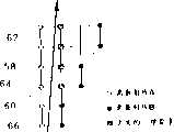
图11为展示取决于不同视域的立方帧缓冲器的抽样率的图;Figure 11 is a graph showing the sampling rate of a cubic framebuffer depending on different views;
图12为按照本发明构成的用于提供来自预定观察方向上的对象的3-D立体投影的设备的另一种形式的功能框图;12 is a functional block diagram of another form of a device for providing a 3-D stereoscopic projection from an object in a predetermined viewing direction according to the present invention;
图13为展示作为立体帧缓冲器的一部分的三维象素束及三维象素数据片段的功能图;Figure 13 is a functional diagram showing voxel bundles and voxel data segments as part of a stereoscopic frame buffer;
图14为本发明的方法的功能图。Figure 14 is a functional diagram of the method of the present invention.
图15为展示用于相邻的三维象素束及投影射线平面的三维象素数据的斜移方案的功能图。Figure 15 is a functional diagram showing a skewing scheme for voxel data for adjacent voxel bundles and projection ray planes.
图16为本发明的用于提供一对象的3-D立体投影的设备的功能框图。FIG. 16 is a functional block diagram of an apparatus for providing 3-D stereoscopic projection of an object according to the present invention.
对最佳实施例的详细说明Detailed Description of the Preferred Embodiment
本发明的方法与设备能够处理数据并支持基于高清晰度三维象素的数据集合的实时显象。本方法与设备设计成用作基于三维象素的系统,这种系统如本申请的发明人Arie Kaufman的已被授权的专利和未决申请所述,所说的专利和未决申请包括:1991年8月6日作为美国专利5,038,302号授权的“在基于三维象素的系统内将连续三维几何表示转换成基于离散三维象素表示的方法”,1991年10月22日作为美国专利4,987,554号而授权的“在基于三维象素的系统内将多面体对象的连续三维几何表示转换成该对象的基于离散的三维象素的表示的方法”;1991年1月15日作为美国专利4,985,856号而授权的“存储、访问与处理基于三维象素的数据的方法与设备”;由于在1993年3月15日作为’593申请的继续申请的美国序列号08/031,599提交而放弃的1989年5月4日提交的序列号为07/347,593的“在基于三维象素的系统内将二次对象的连续三维几何表示转换成基于离散的三维象素的表示的方法”;1992年3月31日作为美国专利5,101,475号而授权的“生成基于三维象素数据的任意投影的方法与设备”;1993年7月26日提交的作为美国序列号08/097,637的“从任意观察方向的实时立体描绘的方法与设备”;以及1992年3月20日提交的作为美国序列号07/855,223的“用离散表示来生成实际图象的方法与设备”,本文引用了这些参考文件的全部公开内容。The method and apparatus of the present invention are capable of processing data and supporting real-time visualization of high-resolution voxel-based data sets. The method and apparatus are designed for use as a voxel-based system as described in issued patents and pending applications of Arie Kaufman, inventor of the present application, including: 1991 Granted August 6, 1991 as U.S. Patent No. 5,038,302 for "Methods for Converting Continuous Three-Dimensional Geometric Representations to Discrete Three-dimensional Pixel-Based Representations in a Voxel-Based System," issued October 22, 1991 as U.S. Patent No. 4,987,554 Granted "Method for converting a continuous three-dimensional geometric representation of a polyhedral object into a discrete voxel-based representation of the object within a voxel-based system"; issued Jan. 15, 1991 as U.S. Patent No. 4,985,856 "Methods and Apparatus for Storing, Accessing, and Processing Voxel-Based Data"; abandoned May 4, 1989 as a result of U.S. Serial No. 08/031,599 filed March 15, 1993 as a continuation of the '593 application "Method for Converting a Continuous Three-dimensional Geometric Representation of a Quadratic Object to a Discrete Voxel-Based Representation in a Voxel-Based System," filed Serial No. 07/347,593; March 31, 1992 as U.S. Patent 5,101,475, "Method and Apparatus for Generating Arbitrary Projections Based on Voxel Data"; "Method and Apparatus for Real-Time Stereo Rendering from Arbitrary Viewing Directions," filed July 26, 1993 as U.S. Serial No. 08/097,637 "; and "Method and Apparatus for Generating Practical Images Using Discrete Representations," filed March 20, 1992 as US Serial No. 07/855,223, the entire disclosures of which references are incorporated herein.
参见图3,本发明的设备20最好包括6个基本组件。这些组件包括:一立方帧缓冲器22,它具有多个能在其中存储三维象素的存储器单元;三个二维(2-D)缓冲器24以及将上述立方帧缓冲器连接于各2-D缓冲器的一个互连机构26。所述立方帧缓冲器为一个组织成n个存储器模块(或存储器片)的三维(3-D)存储器,其中,如在上述参考文件中所描述的那样,每个存储器模块均具有n2个存储器单元,立方帧缓冲器还包含一个独立的双访问与寻址单元(未示出在图中)。如在上述参考文件中所描述的那样,3-D斜移存储器组织能无冲突地访问任何束(即平行于该立方帧缓冲器的主轴的射线)。所述设备还包括一个插值机构28、遮蔽机构30及投影机构32。Referring to Figure 3, the
立方帧缓冲器22的寻址单元将三维象素映射到立方帧缓冲器的特定存储器单元中以便提供三维象素束的无冲突访问。具体地说,将具有空间坐标(x,y,z)的一个三维象素按下式映射到第K个存储器模块上:The addressing unit of the
k=(x+y+z)mod n 0≤k,x,y,z≤n-1k=(x+y+z)
由于是这样访问三维象素束的:使得两个坐标永远是常数,第三坐标保证只有来自一条相应的束的一个三维象素会位于存储器模块的任何一个中。Since voxel bundles are accessed such that two coordinates are always constant, the third coordinate ensures that only one voxel from a corresponding bundle will be located in any one of the memory modules.
本发明的各2-D缓冲器24均为具有2n2-n个存储器单元的2-D三维象素存储装置。立方帧缓冲器22由互连机构26连接在2-D缓冲器24上。此后称作“快速总线”的互连机构为支持数据(三维象素束)从立方帧缓冲器到2-D缓冲器的高带宽传送的互连网。快速总线控制三维象素束,包含斜移、去斜移、散开及收拢三维象素束,以便支持平行与透视投影。在一个最佳实施例中,快速总线采用了带有相关的控制单元的多路复用器与收发器以及一条多信道总线来达到实时立体显象所要求的数据传送速度。Each 2-
立体显象设备中所用的三维象素可由数据采集装置23(诸如扫描器或机器可读信息(M.R.I.)装置)或其它本技术中已知的机构提供。The voxels used in the stereoscopic display device may be provided by a
参见图4,其中示出了用于具有n=512的立方帧缓冲器22及具有32条总线信道的快速总线的快速总线配置的最佳形式。如图中所示,将立方帧缓冲器的512个存储器模块分成32个各有16个存储器模块的组。结果,存储器模块0-15在快速总线的信道0上传送三维象素信息,存储器模块16-31在快速总线的通道1上传送三维象素信息,以此类推,从而存储器模块496-511在快速总线的通道31上传送三维象素信息。Referring to FIG. 4, there is shown a preferred form of the Fast Bus configuration for a
如上所述,快速总线包含多个多路复用器25,因此将来自立方帧缓冲器22的存储器模块(0-511)的三维象素数据时分多路复用到上述存储器模块组的指定的16位快速总线通道上。表1示出了在快速总线上时分多路复用的存储器模块数据。信号多路复用是通过利用带有与各存储器模块相关的收发器27的时钟输入达到的。As mentioned above, the fast bus contains a plurality of multiplexers 25, so that the voxel data from the memory modules (0-511) of the
表1
如图4中所示,将2-D缓冲器分成32组,其中,各组包含16个存储器模块.对于2-D缓冲器的各存储器模块组来说,将来自快速总线的32条通道的三维象素数据提供给16个存储器模块组的相应的存储器模块。As shown in Figure 4, the 2-D buffers are divided into 32 groups, where each group contains 16 memory modules. For each memory block set of the 2-D buffer, voxel data from the 32 lanes of the fast bus is provided to the corresponding memory blocks of the 16 memory block sets.
多路复用器25与收发器27的操作受通常称之为总线通道图的查找表的控制。总线通道图是根据选定的观察参数(即观察方向等)事先计算出来的。选定的观察参数的变化要求重新计算上述查找表。然而,查找表的有限大小允许在不影响系统提供实时立体显象及处理的情况下进行重新计算。The operation of multiplexer 25 and transceiver 27 is controlled by a look-up table commonly referred to as a bus lane map. The bus channel map is calculated in advance based on the selected viewing parameters (ie, viewing direction, etc.). Changes in selected observation parameters require recalculation of the aforementioned lookup tables. However, the limited size of the look-up table allows recalculations to be performed without affecting the system's ability to provide real-time stereoscopic visualization and processing.
参见图3,本发明的设备20最好还包括一个连接在2-D缓冲器24上的插值机构28。在本发明的一个最佳实施例中,该插值装置为一个三线性(TRILIN)插值机构,它可接收关于最好从选定的观察位置通过立方帧缓冲器24投射的连续视线的信息。沿各视线的平均分隔的位置上指示出样本点。为了确定样本点的插入三维象素值,插值机构利用对应于接近各视线样本点的象素点的三维象素数据进行三线性插值。这些插入的三雏象素值用来提供更精确的立体显象图象。Referring to FIG. 3 , the
本发明的设备还可包含一个连接在插值机构22上的遮蔽机构30。另外,也可将遮蔽机构直接连到各2-D缓冲器24上。在本发明的一个最佳实施例中,遮蔽机构接收来自插值机构的视线与样本点信息。此后,遮蔽机构接收靠近各视线样本点的三维象素数据值。更具体地说,遮蔽机构接收紧靠左、右、上、下的离散三维象素射线以及接近当前样本点的视线样本点的值。根据所提供的三维象素信息,通过取接近各样本点的所有三维象素值之差来确定各样本点的梯度矢量,以指示对象的特征中的变化的方向与数量。The device of the invention may also include a
图5A与5B示出两种不同的梯度估算方案。最简单的方法(未示出)为6邻域梯度。这一方法利用沿连续射线的相邻样本值之差,即X方向上的P(n,m+1)-P(n,m-1)及Y方向上的P(n+1,m+1)-P(n-1,m-1)。虽然左、右、上、下射线样本在同一平面内且互相垂直,但射线的Y方向上的样本则不然。更重要的是,当观察方向的变化导致从m到n的主轴的变化时,就用P(n+1,m)-P(n-1,m)的值来计算X方向上的梯度。这会导致可观的运动混淆。5A and 5B illustrate two different gradient estimation schemes. The simplest method (not shown) is the 6-neighborhood gradient. This method uses the difference of adjacent sample values along successive rays, that is, P(n,m+1)-P(n,m-1) in the X direction and P(n+1,m+ 1)-P(n-1, m-1). While left, right, up, and down ray samples are in the same plane and perpendicular to each other, samples in the ray's Y direction are not. More importantly, when the change of viewing direction results in a change of the main axis from m to n, the value of P(n+1,m)-P(n-1,m) is used to calculate the gradient in the X direction. This can cause considerable motion aliasing.
在本发明的一种最佳形式中,如图5A中所示,混淆问题是通过执行一次附加的线性插值来防止的。这一附加步骤包括在与当前样本点正交的(黑色样本)位置上重新对邻域射线抽样。这一方法通常称作10邻域梯度估算,并且它解决在对象转动中切换主轴的问题。In a preferred form of the invention, as shown in Figure 5A, the aliasing problem is prevented by performing an additional linear interpolation. This additional step consists of resampling the neighborhood rays at orthogonal (black sample) locations to the current sample point. This method is often called 10-neighborhood gradient estimation, and it solves the problem of switching axes during object rotation.
参见图5B,说明26邻域梯度的应用。不是从四条相邻的射线中取得样本值,而是从8条相邻的射线中取得26个插入样本,并且,通过取相邻的平面内部与它们之间的差的加权和(即在确定梯度时将最大的权赋予最接近样本点的三维象素)来估算梯度。这一方法能产生较好的总体图象质量,但主轴的切换仍然是明显的,尽管这种切换小于用6邻域梯度方法。See Figure 5B for an illustration of the application of 26 neighborhood gradients. Instead of taking sample values from four adjacent rays, 26 interpolated samples are taken from eight adjacent rays, and, by taking the weighted sum of the adjacent plane interiors and the differences between them (i.e., in determining The largest weight is given to the voxel closest to the sample point) to estimate the gradient. This method produces better overall image quality, but the switching of the main axes is still noticeable, although this switching is smaller than with the 6-neighborhood gradient method.
在图5C与5D中所示的本发明的另一种形式中,通过执行一次附加的线性插值来防止混淆问题。这一附加步骤包括在与基平面正交的(白色样本)位置上重新对邻域射线抽样。根据这些新位置的位置,或者必须执行双线性插值或者必须执行线性插值。这些方法通常分别称作12邻域与8邻域梯度估算。这些方法中的每一种方法都能解决在对象转动中切换主轴的问题并提供垂直于数据集合的主轴的梯度矢量。In another form of the invention shown in Figures 5C and 5D, the aliasing problem is prevented by performing an additional linear interpolation. This additional step consists of resampling the neighborhood rays at positions normal to the base plane (white samples). Depending on the position of these new positions, either bilinear interpolation or linear interpolation must be performed. These methods are commonly referred to as 12-neighborhood and 8-neighborhood gradient estimation, respectively. Each of these methods solves the problem of switching the main axis during object rotation and provides a gradient vector perpendicular to the main axis of the data set.
在透视投影情况中,用相距一个单元的n条射线均匀地对各投影射线平面(PRP)的前面抽样。随着射线向立方帧缓冲器、立体的背面扩散,射线之间的距离会增加,从而利用如前面说明的平均值。In the perspective projection case, the front of each projection ray plane (PRP) is sampled uniformly with n rays one unit apart. As the rays spread towards the cubic framebuffer, the back of the volume, the distance between the rays increases, taking advantage of the averaging as explained earlier.
遮蔽机构最好还包含一光矢量查找表。通过知道梯度值及光矢量查找表的值,便能用多种多样的遮蔽法(诸如用本技术中所知的集成Phong遮光器)生成各样本点的亮度。为了显示样本点上的半透明度,利用表示为用样本密度加以索引的查找表的转移函数生成不透明度值。Preferably, the shading mechanism also includes a light vector lookup table. By knowing the gradient value and the value of the light vector look-up table, the brightness of each sample point can be generated using a variety of shading methods, such as with integrated Phong shutters known in the art. To display translucency at sample points, opacity values are generated using a transfer function represented as a lookup table indexed by sample density.
参见图3并且如前所述,本发明最好还包括一个投影机构(RPC)32。该投影机构接收来自插值机构28的插入三维象素值(它对应于视线样本点)、以各种方法之一将这些插入三维象素值组合起来、并为各视线生成一个象素值。这一象素值对应于正在相应的象素位置上表示的对象或空间的彩色、不透明度与结构。投影机构最好能用从后到前合成、从前到后合成、第一不透明体投影、加权和投影、最后到第一断层投影或第一到最后断层投影(它提供具有特定厚度的对象或区域的剖面的立体显象)之一来将插入三维象素值组合起来。Referring to FIG. 3 and as previously described, the present invention preferably also includes a projection mechanism (RPC) 32 . The projection mechanism receives interpolated voxel values (which correspond to line-of-sight sample points) from
在本发明的最佳实施例中,投影机构为一射线投影圆锥(RPC),它采用上述各种投影方案每一时钟周期均生成一个象素值信号。如图6中所示,射线投影机构包含多个输入端口34,它们用于接收多条连续视线中各条视线的多个插入样本信号。连在多个输入端口34的各个端口上的是多个三维象素组合级36。每个三维象素组合级均包括多个三维象素组合单元(VCU)38。如图6中所示,每一个后面的三维象素组合级均包括比前一个三维象素组合级少的VCU。各VCU最好连在三个输入端口34上。然而,在上述最佳实施例中,RPC设计成只选择二个插入样本信号,这两个信号来自三个输入端口或前面的VCU中的两个端口或两个VCU。具体地说,根据所选择的观察方案,各VCU将左与中或右与中的连接选作输入以便接收输入信号。In a preferred embodiment of the present invention, the projection mechanism is a ray projection cone (RPC) which generates a pixel value signal per clock cycle using the various projection schemes described above. As shown in FIG. 6, the ray projection mechanism includes a plurality of
如图6中所示,RPC为带有n个树叶的折叠(环形)交叉链接二叉树,它能动态地映射到一棵树上,该树的最左侧树叶在RPC的任意端节点上。这就允许处理三维象素视线,从而,能将射线的第一个三维象素提供给RPC的任何输入端口。这又允许将圆锥硬接线到包含三维象素的2-D缓冲器的输出端上。这一结构消除了对用于2-D缓冲器数据的去斜移的一组n个n对1开关单元或桶形移位器的需求,它们在先有技术射线投影机构中是需要的。在本发明的一个最佳实施例中,圆锥的叶中包含TRILIN与遮蔽机构。As shown in Fig. 6, RPC is a folded (circular) cross-linked binary tree with n leaves, which can be dynamically mapped to a tree whose leftmost leaf is on any end node of RPC. This allows voxel line-of-sight to be processed so that the first voxel of the ray can be supplied to any input port of the RPC. This in turn allows the cone to be hardwired to the output of the 2-D buffer containing the voxels. This structure eliminates the need for a set of n n-to-1 switch cells or barrel shifters for de-skewing the 2-D buffer data, which are required in prior art ray projection mechanisms. In a preferred embodiment of the invention, the lobes of the cone contain the TRILIN and the shielding mechanism.
最佳的是,RPC将一组沿所述视线的几个插入样本信号接收为输入并为对应于相关视线的象素生成一个象素值信号。如图6中所示,该圆锥为n-1个初级计算节点VCU的分层流水线。在任何给定的时间帧上,圆锥正在以流水作业方式同时处理log n条视线,从而每一时钟周期均为显示器的一个象素生成一个对应的新象素值信号。Most preferably, the RPC receives as input a set of several interpolated sample signals along said line of sight and generates a pixel value signal for a pixel corresponding to the associated line of sight. As shown in Figure 6, the cone is a hierarchical pipeline of n-1 primary compute node VCUs. At any given time frame, the cone is pipelined for log n views simultaneously, generating a corresponding new pixel value signal for each pixel of the display every clock cycle.
可将各三维象素的不透明度与每一三维象素一起预先存储,或者通过在圆锥的叶上的遮蔽机构内部的查找表或转移函数来提供所说的不透明度。在一个最佳实施例中,VCD通过执行下述运算之一生成一个输出信号:The opacity of each voxel can be pre-stored with each voxel or provided by a look-up table or transfer function internal to the shading mechanism on the lobes of the cone. In a preferred embodiment, the VCD generates an output signal by performing one of the following operations:
第一不透明体:如果(αL不透明)则V′=VLThe first opaque body: if (αL is opaque) then V'=VL
否则 V′=VROtherwise V'=VR
最大值:如果(CL<CR)则V′=VRMaximum value: if (CL <CR ) then V'=VR
否则 V′=VLOtherwise V'=VL
加权和:C′=CL+WKCRWeighted sum: C'=CL +WK CR
其中,W为加权因子,K为圆锥级(即三维象素组合级的数目)。WK是预先计算的并预先加载进VCU中。应指出,加权和对于深度插入、明视场及X射线射影是有用的。合成是由下式确定的:Wherein, W is a weighting factor, and K is a cone level (that is, the number of three-dimensional pixel combination levels). WK is precomputed and preloaded into the VCU. It should be noted that weighted sums are useful for depth interpolation, bright field and X-ray projection. Synthesis is determined by:
C′=CL+(1-αL)CRC'=CL +(1-αL )CR
α′=αL+(1-αL)αRα'=αL +(1-αL )αR
其中,第一级CVU计算CI=CIαI,假定这些值为灰度级。这实际上是并行地实现从前到后(或从后到前)合成。将象素值传输到诸如通用主计算机或象素处理器42,在其中执行诸如后遮蔽、溅散与2-D变换或弯曲等后处理。Wherein, the first-level CVU calculates CI =CI αI , assuming that these values are gray levels. This actually implements front-to-back (or back-to-front) compositing in parallel. The pixel values are transferred to, for example, a general purpose host computer or
参见图3,本发明的设备还可包括连接在投影机构上的帧缓冲器40、象素处理器42及显示装置44。最好将投影机构32所生成的象素值信号提供给存储各象素值信号的帧缓冲器40、提供给象素处理器42以进行2-D变换、滤波或弯曲,此后提供给显示装置44以进行视觉显示。如本技术中所知的那样,象素处理器42变换象素值信号使之能正确地显示在显示装置上。Referring to FIG. 3, the apparatus of the present invention may further include a
参见图7-11说明确定插入样本值信号的插值机构28与方法。本发明的插值机构28通过8个周围三维象素并按下式进行插入而在非三维象素的位置上生成一个三维象素值信号:Referring now to Figures 7-11, the
Pabc=P000(1-a)(1-b)(1-c)+P100a(1-b)(1-c)+Pabc =P000 (1-a)(1-b)(1-c)+P100 a(1-b)(1-c)+
P010(1-a)b(1-c)+P001(1-a)(1-b)c+P010 (1-a)b(1-c)+P001 (1-a)(1-b)c+
P101a(1-b)+P011(1-a)bc+P101 a(1-b)+P011 (1-a)bc+
P110ab(1-c)+P111abc.P110 ab(1-c)+P111 abc.
一个相应的样本点在立方帧缓冲器内相对于最接近原点的角三维象素的相对3-D坐标为(a,b,c)。与立方帧缓冲器的角三维象素相关的数据值为Pijk,其中i,j,k=0或1,而与样本点相关的插入数据值为Pabc。不同的优化旨在减少这一方法的计算复杂性,但取出各样本点的8个邻接三维象素的任何存储器访问均会使之成为立体描绘中最耗时间的操作。The relative 3-D coordinates of a corresponding sample point within the cubic framebuffer with respect to the corner voxel closest to the origin are (a, b, c). The data values associated with the corner voxels of the cubic frame buffer are Pijk , where i,j,k=0 or 1, and the interpolated data values associated with the sample points are Pabc . Various optimizations are aimed at reducing the computational complexity of this method, but any memory access to fetch the 8 adjacent voxels for each sample point would make this the most time-consuming operation in volume rendering.
通过变换存储在立方帧缓冲器中的PRP的离散射线从而使它们对准,并将它们存储在上述两个2-D缓冲器中,能够极大地减少数据存取时间。不是取出各重新抽样位置的三维象素的8个邻域而是从缓冲器中取出四条离散射线,即:从当前射线的上、下投影射线平面(PRP)中各取两条射线。这些投影射线平面是从2-D缓冲器中提供的。在插值法的并行实现中,邻接射线位于邻接插值模块中,从而只需要邻居之间的一个三维象素单元的一次本地移位操作。By transforming the discrete rays of the PRP stored in the cubic frame buffer so that they are aligned, and storing them in the two 2-D buffers mentioned above, the data access time can be greatly reduced. Instead of fetching 8 neighborhoods of voxels for each resampled position, four discrete rays are fetched from the buffer, ie, two rays each from the projected ray plane (PRP) above and below the current ray. These projection ray planes are provided from a 2-D buffer. In a parallel implementation of the interpolation method, adjacency rays are located in the adjacency interpolation module so that only one local shift operation of one voxel unit between neighbors is required.
图7A与7B中示出一种插值法。参见图7A,利用邻近的离散射线50(白)与52(黑)的样本之间双线性插值插入连续射线48上的样本点46。可利用来自离散射线50、52的四个三维象素正确地插入连续射线48的第一样本点,因为,四个三维象素构成一个矩形(即射线并不向左或右进一离散步)。One interpolation method is shown in Figs. 7A and 7B. Referring to FIG. 7A , sample points 46 on continuous rays 48 are interpolated using bilinear interpolation between samples of adjacent discrete rays 50 (white) and 52 (black). The first sample point of the continuous ray 48 can be correctly interpolated using the four voxels from the discrete scatter rays 50, 52 because the four voxels form a rectangle (i.e. the ray does not go left or right by a discrete step ).
一旦如在沿连续射线48的第二与第四样本的情况那样所述离散射线向左或右步进,四个邻接的三维象素便会构成一个平行四边形,从而,直接的双线性插值不能提供精确的三维象素样本值。因此,需要带灰色阴影的正方形三维象素54、56以产生更精确的结果。然而,这些三维象素却位于离开连续射线48两个单位的离散射线上。Once the discrete ray is stepped left or right as in the case of the second and fourth samples along the continuous ray 48, four contiguous voxels form a parallelogram, so that direct bilinear interpolation Exact voxel sample values cannot be provided. Therefore, the gray shaded square voxels 54, 56 are required to produce more accurate results. However, these voxels lie on discrete scatter lines two units away from the continuous ray 48 .
参见图7B,其中对透视投影示出了不利用最佳三维象素点来提供插入样本信号的问题。由于对透视观察来说离散射线是扩散的,所以,正确的相邻三维象素并不存储在2-D缓冲器中。例如,只有离散射线62的两个三维象素58、60对连续射线66的第三样本点64的正确插值起作用。在3-D情况中,对于透视投影来说,在样本点64的紧接邻域中可丢失多达6个三维象素。See Fig. 7B, where the problem of not utilizing the best voxel points to provide the interpolated sample signal is shown for perspective projection. Since discrete rays are diffuse for perspective viewing, the correct adjacent voxels are not stored in the 2-D buffer. For example, only the two
解决方案是将所述方法分成四次线性及一次双线性插值从而执行剪切三线性插值。不是象前述方法中所做的那样相对于最接近原点的角三维象素指定样本位置,而是沿连续射线的各3-D坐标中包含有用于沿可能的剪切三维象素邻域中的各轴的线性插值的相对加权值。可预先计算这些加权值并将其存储在模板中。The solution is to split the method into quartic linear and once bilinear interpolation to perform clipped trilinear interpolation. Instead of specifying the sample position relative to the corner voxel closest to the origin as done in the previous method, each 3-D coordinate along the successive rays contains the Relative weighting values for linear interpolation for each axis. These weighted values can be precomputed and stored in templates.
参见图8A-8D,它们示出了用于平行投影(图8A与图8C)及透视投影(8B与8D)的3-D中插值所需要的步骤。首先,利用存储在2-D缓冲器中的四条相邻离散射线的8个三维象素在主轴方向上(Z轴为连续射线的主行进方向)执行四次线性插值。如图8A与8B中所示,这8个三维象素是用于平行投影的斜平行六面体的或用于透视投影的截头四棱锥体的8个顶点。四个三维象素各位于相距一个单位的两个分离的平面上,它们按着穿过主轴方向的射线遇到的先后次序,通常称作前或后平面。因此,只需对应于前平面与射线样本点之间的距离存储一个加权因子。得出的四个插入值构成一个矩形并能将其双线性地插入以产生最终的插入抽样值。这一双线性插值分成角值之间的两次线性插值及边值之间的最终线性插值。图8C与8D中,这称作X方向上的两次插值,其后是在Y方向上的一次插值。See Figures 8A-8D, which illustrate the steps required for interpolation in 3-D for parallel projections (Figures 8A and 8C) and perspective projections (8B and 8D). First, quartic linear interpolation is performed in the principal axis direction (Z-axis is the main travel direction of continuous rays) using 8 voxels of four adjacent discrete rays stored in a 2-D buffer. As shown in FIGS. 8A and 8B, the eight voxels are the eight vertices of an oblique parallelepiped for parallel projection or a truncated quadrangular pyramid for perspective projection. Each of the four voxels lies on two separate planes one unit apart, in the order in which they are encountered by a ray passing through the direction of the principal axis, usually called the front or back plane. Therefore, only one weighting factor needs to be stored corresponding to the distance between the front plane and the ray sample point. The resulting four interpolated values form a rectangle and can be interpolated bilinearly to produce the final interpolated sample values. This bilinear interpolation is split into two linear interpolations between the corner values and a final linear interpolation between the edge values. In Figures 8C and 8D, this is referred to as two interpolations in the X direction, followed by one interpolation in the Y direction.
对应于连续射线的样本点最好位于四条周围离散射线上的三维象素所限定的多面体的内部。在构成离散射线时,所有连续射线都始于基平面的整数位置(即它们与立体数据集的第一片段的三维象素重合)。如图9中所示,在射线投射中采用这些射线能有效地将三线性插值降级成双线性插值,因为沿射线的所有样本点都落在平行六面体或截头四棱锥体的前平面上。The sample points corresponding to the continuous rays are preferably located inside the polyhedron defined by the voxels on the four surrounding discrete scatter lines. In forming discrete rays, all successive rays start at integer positions of the base plane (ie they coincide with the voxels of the first segment of the volume dataset). As shown in Figure 9, employing these rays in ray casting effectively degrades trilinear interpolation to bilinear interpolation, since all sample points along the ray fall on the front plane of the parallelepiped or truncated pyramid .
参见图9(无位移图),利用基平面上的X与Y整数位置允许在射线穿过的主方向上相对基平面的位移作为自由度,并使剪切三线性插值能够进行。然而,如图9(越出范围位移图)中所示,对于主方向上相对较大的位移来说,沿射线的某些样本可能会落在离散射线所限定的边界框外面。Referring to FIG. 9 (displacement-free graph), the use of X and Y integer positions on the base plane allows displacement relative to the base plane in the main direction through which the ray passes as a degree of freedom and enables shear trilinear interpolation. However, as shown in Figure 9 (out-of-range displacement map), for relatively large displacements in the main direction, some samples along the ray may fall outside the bounding box defined by the discrete ray.
参见图10,将一个连续观察矢量分解成X轴上的dx分量(3-D中dx与dy)与主轴(Y轴)方向上的一个单位矢量。通过沿主轴方向步进,为了得到新的样本位置,可将观察矢量加在当前样本位置上。Referring to Fig. 10, a continuous observation vector is decomposed into a dx component on the X axis (dx and dy in 3-D) and a unit vector in the direction of the main axis (Y axis). By stepping in the direction of the main axis, the view vector can be added to the current sample position in order to obtain a new sample position.
假定在当前样本位置上加上dx会导致离散射线在X方向上的步进。只有在当前样本位置相对于左下角三维象素就正的dx而言具有大于1-dx(或者就负的dx而言小于1+dx)的相对X位移时才出现这一步进。换言之,当前样本位置处于如图10所示的具有dx乘1的边的矩形内部。然而,只有这一矩形的阴影区中包含着由角三维象素限定的平行六面体内的样本位置。取主轴上的最小边作为最坏情况,这意味着对于正的dx来说,范围内的样本具有不大于1-dx的最大相对y位移(对于负的dx来说不小于1+dx)。Assume that adding dx to the current sample position will cause the discrete ray to step in the X direction. This step only occurs if the current sample position has a relative X displacement greater than 1-dx for positive dx (or less than 1+dx for negative dx) relative to the bottom left voxel. In other words, the current sample position is inside a rectangle with
由于步进是靠主轴方向上的单位矢量执行的,所以,沿连续射线的所有相对位移均取决于第一射线样本相对基平面的位移。以上结论很容易推广到3-D上,使主轴方向上的最大的允许位移成为:Since stepping is performed by a unit vector in the direction of the principal axis, all relative displacements along successive rays depend on the displacement of the first ray sample relative to the base plane. The above conclusions can be easily extended to 3-D, so that the maximum allowable displacement in the direction of the main axis becomes:
min(1-dx,1-dy), dx,dy≥0min(1-dx, 1-dy), dx, dy≥0
min(1+dx,1-dy), dx<0,dy≥0min(1+dx, 1-dy), dx<0, dy≥0
min(1-dx,1+dy), dx≥0,dy<0min(1-dx, 1+dy), dx≥0, dy<0
min(1+dx,1+dy), dx,dy<0,min(1+dx, 1+dy), dx, dy<0,
其中,dx与dy分别为观察矢量在x与y方向上的分量。注意,对于45°视角来说,dx与dy为1,从而产生位移0以及图9中所示的双线性插值。Among them, dx and dy are the components of the observation vector in the x and y directions, respectively. Note that for a viewing angle of 45°, dx and dy are 1, resulting in a displacement of 0 and the bilinear interpolation shown in Figure 9.
在本发明的上述最佳实施例中,用样本之间的均匀距离将一条单一的射线从图象平面的原点发射到基平面上,并在射线穿过基平面之后沿第一样本的主方向选择位移。必要时,重复地减小所述位移直到满足以上条件为止。这就会导致沿行进的主方向有依赖于观察的位移及对数据集的不定的重新抽样。根据观察方向的重新抽样点的变化是交互式显象的一个优点,因为,这能揭示更多的内部数据结构。In the above-described preferred embodiment of the present invention, a single ray is launched from the origin of the image plane onto the base plane with a uniform distance between the samples, and after the ray passes through the base plane, it travels along the principal axis of the first sample. Direction selection displacement. If necessary, the displacement is repeatedly reduced until the above condition is satisfied. This results in an observation-dependent displacement along the main direction of travel and an indeterminate resampling of the dataset. The change of resampling points according to the viewing direction is an advantage of interactive visualization, because it can reveal more internal data structures.
各离散射线包含n个三维象素,它们与观察方向无关。由于与主轴的最大视角差不大于45度,所以,立体抽样率是由通过立方体的对角线所限定的并且是正交观察的
更严重的问题是样本邻域的变化范围。对于平行投影,包围样本点的8个三维象素或者构成一个边长为一的立方体或者构成图8A中所示的一个斜平行六面体。但是,对于透视投影来说,周围的三维象素可构成图8B中的带有平行的前与后平面的截头四棱锥体。由于射线向数据集后方的扩散,这一截头锥体覆盖的列会增加,从而降低了三线性插值的精度。然而,业已发现,对于2563的数据集,相邻的离散射线之间的距离在立体结束处永远不会超过两个三维象素,同时仍能获得高度的透视性。再者,在典型的数据集中,立体背面的样本由于沿射线的合成而对最终象素彩色影响很小。A more serious problem is the range of variation in the sample neighborhood. For parallel projection, the 8 voxels surrounding the sample point form either a cube with side length one or an oblique parallelepiped as shown in FIG. 8A. However, for perspective projection, the surrounding voxels can form a truncated quadrangular pyramid with parallel front and back planes as in Figure 8B. As the rays spread out towards the back of the dataset, the columns covered by this frustum increase, reducing the accuracy of trilinear interpolation. However, it has been found that for the 2563 data set, the distance between adjacent discrete rays is never more than two voxels at the stereo end, while still achieving a high degree of perspective. Furthermore, in typical datasets, the volume back samples have little effect on the final pixel color due to composition along the rays.
透视投影中的投影中心(C)与视域(FOV)也影响抽样率。离散线算法在每一基平面象素上正好投射一条射线,或者每一条扫描线最多2n条射线。参见图11,在FOV延伸跨越数据集的情况下,就能保证比正常图象次序射线投射有更好的抽样,后者会投射出n条扫描FOV的射线并发出不命中数据集的无用射线。然而,对于小的FOV来说,离散线步进会在基平面的活跃区中产生抽样不足。图11的第三示例示出两个基平面图象对最终视图象起作用的情况。对单一透视图象来说,这是在生成三个基平面的投影时的最坏情况。The projection center (C) and field of view (FOV) in perspective projection also affect the sampling rate. The discrete line algorithm casts exactly one ray on each base plane pixel, or at most 2n rays per scanline. See Figure 11, where the FOV extends across the dataset, this guarantees better sampling than normal image order raycasting, which casts n rays that scan the FOV and emit useless rays that miss the dataset . However, for small FOVs, discrete line stepping produces undersampling in the active region of the base plane. The third example of Figure 11 shows the case where two base plane images contribute to the final view image. For a single perspective image, this is the worst case in generating projections of the three base planes.
从以上描述中显而易见,由于包含在本发明中的插值与遮蔽,本发明的设备与方法提供了对正在显示的对象或景象的更精确的表示。此外,由于本发明并不需要先有技术装置中使用的传送器或类似装置,所以,本发明的设备比先有技术系统能更高效与更快地进行操作,因为,数据处理是以高度并行方式“飞速”执行的。具体地说,与在0(n2logn)时间内完成操作的先有技术系统相比,本设备与方法可在0(n2)时间内完成操作。此外,由于互连机构既能执行平行投影的去斜移又能执行透视投影的收拢(即一种数据压缩方式),所以,本发明能够支持透视投影及四维(4-D)数据的实时显象。As apparent from the above description, the apparatus and method of the present invention provide a more accurate representation of the object or scene being displayed due to the interpolation and occlusion involved in the present invention. Furthermore, since the present invention does not require conveyors or the like used in prior art devices, the apparatus of the present invention can operate more efficiently and faster than prior art systems because data processing is highly parallel The way "flying" execution. Specifically, the present apparatus and method can complete operations in 0(n2 ) time as compared to prior art systems that complete operations in 0(n2 logn ) time. In addition, because the interconnection mechanism can not only perform parallel projection de-skewing but also perform perspective projection shrinking (that is, a data compression method), the present invention can support perspective projection and real-time display of four-dimensional (4-D) data. elephant.
参见图12,其中示出本发明的另一实施例70。本发明的另一实施例的设备最好包括一个立方帧缓冲器(CFB)22,它具有多个如上面描述的能在其中存储三维象素数据的存储器单元。本发明的上述另一形式的立方帧缓冲器可包含一个能够进行无冲突访问任何三维象素束72(即平行于立体帧缓冲器的主轴的射线)的3-D斜移存储器组织,如图13中所示。上述设备还包含一个第一二维缓冲器73、一个插值机构(TRILIN)28、两个二维缓冲器24、遮蔽机构30及合成机构74。连在合成机构的输出端上的是用于生成三维(3-D)立体投影图象的一个象素处理器42、帧缓冲器40及显示装置44。必要时,象素处理器42与帧缓冲器40的相对位置可以互换。Referring to Figure 12, another
在本发明的另一形式中,所说的方法包括为显示装置44的多个象素中每一个象素均生成一条视线。在各视线穿过CFB时,视线可改变其X、Y与Z坐标中任何一个。上述多条视线限定了通过立方帧缓冲器的观察方向。上述方法还包括生成沿各视线的等间隔样本点。为了将一个值信号分配给视线上的各样本点,利用分配给CFB内的三维象素的值来进行插值处理。具体地说,从立方帧缓冲器中检索出三维象素束。一条三维象素束是平行于立方帧缓冲器的主轴(X,Y或Z)的三维象素的任何离散的行、列或轴。在本发明的一个实施例中,接连地检索出包含n束三维象素的两个n×1三维象素数据信号片段76(如图13中所示)并将其提供给插值机构28。这些三维象素数据信号片段可以基本上平行于3-D存储器的主轴(即平行于基平面的法线)或基本上垂直于3-D存储器的主轴(即平行于基平面)。虽然将两个完整的n×1三维象素数据片段提供给插值机构并将它们用于多条视线中的各条视线,如上所述,但为了简化起见,将限于一组视线进行说明。In another form of the invention, the method includes generating a line of sight for each of a plurality of pixels of the
在本发明的另一实施例中,接连地检索出包含n束三维象素的一个n×1三维象素数据信号片段76(如图13中所示)并将其提供给插值机构28。这些三维象素数据信号片可以基本上平行于3-D存储器的主轴(即平行于基平面的法线)或基本上垂直于3-D存储器的主轴(即平行于基平面)。对于平行观察来说,插值机构为一个双线性或高阶装置。另一方面,对于透视观察来说,插值机构为一个线性或高阶装置,它利用了n×1片段内的较大的三维象素邻域。预见到不仅可利用三维象素数据的一个片段,而且可访问多片段以便生成插入样本点信号。In another embodiment of the present invention, an
参见图14,其中示出了本发明的一个实施例。穿过立方帧缓冲器22的多条视线78中的每一条视线(及其上面的对应样本点)均由CFB内的两个投影射线平面(PRP)所限定。这两个PRP通常称作顶PRP80及底PRP82。本发明的方法包括访问来自顶PRP80的第一三维象素信号束81及来自底PRP82的第一三维象素信号束83。将各三维象素束81、83提供给插值机构的“背面”输入端,如图14中所示。Referring to Figure 14, one embodiment of the present invention is shown. Each of the plurality of lines of
参见图15,它显示出从立方帧缓冲器(CFB)存储器上移开了顶与底PRP80、82。根据前述斜移方案,具有3-D坐标X,Y与Z的三维象素数据在物理上存储于存储器模块号Referring to Figure 15, it is shown that the top and
K=(X+Y+Z)mod n (0≤k,x,y,z≤n-1)之中,其中,n为立方存储器的大小。平面中的数字表示给定一定的Y与Z坐标时将从模块K中读取的一个三维象素的X坐标。从图中显而易见,来自同一PRP中的相邻束的三维象素与来自不同PRP的相邻束的三维象素具有不同的X坐标次序(即斜移差1)。本发明中,对相邻三维象素束之间的这一斜移差进行补偿,以便在访问三维象素数据信号时通过提供移位来对准各三维象素束的适当三维象素值(即具有相同X坐标值的三维象素)。K=(X+Y+Z)mod n (0≤k, x, y, z≤n-1), where n is the size of the cubic memory. The numbers in the plane represent the X coordinate of a voxel to be read from module K given certain Y and Z coordinates. It is apparent from the figure that voxels from adjacent bundles in the same PRP have a different X-coordinate order (ie, a skew difference of 1) than voxels from adjacent bundles in a different PRP. In the present invention, this skew difference between adjacent voxel bundles is compensated to align the proper voxel values for each voxel bundle by providing a shift when accessing the voxel data signal ( i.e. voxels with the same X coordinate value).
如图14中所示,最好通过在不使三维象素数据信号移位的情况下将底PRP82提供给插值机构28的背面、并在负K方向上移位一个单位的情况下将顶PRP80提供给插值机构的背面,从而来实现三维象素数据信号的对准。As shown in FIG. 14, it is preferable to provide the
本发明的方法还包括在下一时钟周期中将第一与第二三维象素平面的第一三维象素束从插值机构的“背面”移动到“正面”。此外,将来自顶PRP80的第二三维象素束及来自底PRP82的第二三维象素束提供给插值机构28的“背面”输入端。由于如图15中所示的各PRP的第一三维象素束与第二三维象素束之间的数据斜移,在将它们从插值机构的“背面”提供给“正面”时,会使顶与底PRP80、82两者的第一三维象素束在正K方向上都移位一个位置。因此,当四个相对的三维象素束出现在插值机构中时,各三维象素束的三维象素会是对准的,从而,会有正确的8个三维象素邻域来为各视线的一个样本点执行三线性插值。结果,四个三维象素束同时位于插值机构中。The method of the present invention also includes moving the first voxel bundles of the first and second voxel planes from "back" to "front" of the interpolation mechanism in a next clock cycle. Additionally, a second voxel bundle from the
上述三维象素从立方帧缓冲器22到插值机构28的“背面”输入端及从插值机构的“背面”输入端到“正面”的移位发生在各时钟周期中。然而,如果存储在立方帧缓冲器中的三维象素数据是未斜移的,则不需要三维象素束、插入样本点信号或遮蔽样本点信号的移位。The shifting of the voxels described above from the
一旦移位了顶与底PRP80、82的第一与第二三维象素束并将它们正确地定向,插值机构28便为各视线的第一样本点生成一个插入样本点信号。Once the first and second voxel bundles of the top and
在本发明的一个最佳实施例中,插值机构28为一个三线性插值机构(TRILIN)。为了执行三线性插值,必须利用构成视线样本点周围的一个小室的8个邻接三维象素。另外,可以利用使用了8个三维象素邻域内部或外部的三维象素的双线性插值或高阶插值机构(即少于或多于8个三维象素值)。In a preferred embodiment of the present invention,
当观察方向(即视线)在Y方向上具有正或负分量时,便采用简单的步进方案来正确地对准相邻三维象素平面中的三维象素束。从立方帧缓冲器到插值机构的“背面”输入端及从插值机构的“背面”输入端到“正面”的步进方案如下:When the viewing direction (ie line of sight) has a positive or negative component in the Y direction, a simple stepping scheme is used to correctly align voxel bundles in adjacent voxel planes. The stepping scheme from the cubic framebuffer to the "back" input of the interpolation mechanism and from the "back" input of the interpolation mechanism to the "front" is as follows:
三维象素在K方向上的移位Y步长 从CFB到背 从背面到正 The displacement Y step size of the voxel in the K direction from the CFB to the back
面的移位 面的移位
一旦确定了插入样本点,所说的方法还包括通过将插入样本点信号提供给缓冲器84以便临时存储在其中而为各插入样本点信号生成一个梯度估算信号。缓冲器最好包含一个上面缓冲器86、当前缓冲器88及下面缓冲器90。然而,所述方法也能用这三个缓冲器中的任何两个来加以实现。梯度估算信号提供特定插入样本点上表面倾斜度的指示。在本发明的一种最佳形式中,需要关于一个特定插入样本点的三对插入样本点信号来生成一个梯度估算信号。鉴于需要三对三维象素,所以能通过确定选定的插入样本点之间的中心差来计算所有方向(上与下、前与后、右到左)上的实际差。Once the interpolation sample points are determined, the method further includes generating a gradient estimate signal for each interpolation sample point signal by providing the interpolation sample point signal to buffer 84 for temporary storage therein. The buffers preferably include an
为了确定主方向(即沿Z观察方向)上的梯度差,遮蔽机构有必要访问当前缓冲器内相隔两个时钟周期的两个插入样本点束(即预定样本的前一个束与后一个束)。In order to determine the gradient difference in the main direction (i.e., along the Z viewing direction), it is necessary for the masking mechanism to access two intervening sample point bundles (i.e., the previous bundle and the next bundle of the predetermined sample) separated by two clock cycles in the current buffer .
图14示出了上面、当前与下面缓冲器86、88、90中各缓冲器同时将一组插入样本点输出到遮蔽机构30。然而,由于三维象素数据在CFB内的斜移,这些插入样本点信号并不象要求的那样在上面、当前与下面缓冲器中对准。为了正确地对准上面与当前缓冲器内的插入样本点信号,最好在遮蔽机构30内将当前缓冲器的插入样本点信号在正的K方向上移位一个位置。为了正确地对准上面与下面缓冲器中的插入样本点信号,最好在遮蔽机构内将下面缓冲器样本点信号在正的K方向上移位两个位置。此外,最好将来自上面与下面缓冲器的插入样本点信号延迟一个时钟周期以便与当前缓冲器中的插入样本点信号对准。移位与延迟的组合补偿了上面、下面与当前缓冲器所提供的插入样本点信号之间的斜移差。FIG. 14 shows each of the upper, current and
利用遮蔽机构30中得到的正确地对准了的插入样本点信号,便可以利用上述遮蔽机构与梯度估算法在每一时钟周期上为各插入样本点信号精确地计算梯度差。最好在紧靠左与右、上与下以及沿视线(即当前样本点的前与后)的插入样本点信号之间取中心差。遮蔽机构最好还包括一个光矢量查找表。通过通知梯度值及光矢量查找表的值,便可用多种遮蔽法(诸如用本技术中已知的集成Phong遮光器)生成各样本点的亮度。如本技术中已知的那样,为了显示一个样本点上的不透明度,可利用按样本密度与/或梯度值访问的最好表示为2-D或3-D查找表的转移函数或其它索引方法来生成不透明度值。Using the correctly aligned interpolation sample point signals obtained in the
当观察方向(即视线)在Y方向上具有单一的正或负分量时,便采用简单的步进或移位方式以便在遮蔽单元中将插入样本值信号与相邻的插入样本值信号组正确地对准。具体地说,从上、下与当前缓冲器到遮蔽机构30有下述插入样本值信号的移位:When the viewing direction (i.e. line of sight) has a single positive or negative component in the Y direction, simple stepping or shifting is used to correctly group the interpolated sample-valued signal with adjacent interpolated sample-valued signals in the masking unit ground alignment. Specifically, there is the following shift of the interpolated sample-valued signal from the upper, lower and current buffers to the masking mechanism 30:
K方向上的插入样本移位Insertion sample shift in K direction
Y步 从ABC缓冲器到 遮蔽机构内Step Y From the ABC buffer to the inside of the shielding mechanism
长 遮蔽机构的移位 的移位
一旦为当前缓冲器的各插入样本点计算出了梯度估算值,便将包括有遮蔽分量的各插入样本点信号提供给沿相应视线对样本点进行合成操作的合成机构74。由于遮蔽机构所输出的遮蔽样本值信号束仍然是斜移的,所以,不能用单一的合成单元来完成单一的正交射线合成,具体地说,在本发明的一个最佳实施例中,视线的各插入样本点是在一个不同的合成机构中合成的。由于两个相邻的三维象素束之间存在斜移差,所以,就图14所示的各个相邻的合成步骤而言,必须向各相邻的合成射线的合成结果提供正K方向上的一个单位步长。对于具有X与/或Y上的步长(正,负或无)的任何视线来说,从遮蔽机构到合成机构的遮蔽样本值信号的移位如下:Once the gradient estimates have been calculated for the interpolated sample points of the current buffer, the interpolated sample point signals including the occlusion component are provided to a
K方向上的梯度样本值移位
合成机构内执行的插入样本点合成基本上按上面说明的同一方法进行。具体地说,合成机构能用从后到前合成法、从前到后合成法、第一不透明体投影法、加权和投影法、最后到第一断层投影法或第一到最后断层投影法中的一种或其它任何已知的合成技术来组合插入三维象素值。The interpolation sample point synthesis performed in the synthesis mechanism is basically performed in the same manner as explained above. Specifically, the compositing mechanism can use one of back-to-front compositing, front-to-back compositing, first opacity projection, weighted sum projection, last-to-first tomographic projection, or first-to-last tomographic projection. The interpolated voxel values are combined by one or any other known compositing technique.
一旦合成了插入样本点,便例如将它们提供给通用主计算机或象素处理器42,在其中执行诸如后遮蔽、溅散与2-D变换或弯曲等后处理。用于在显示装置44上显示的象素处理最好象前面说明的那样进行。Once the interpolation sample points are synthesized, they are provided, for example, to a general purpose host computer or
在本发明的另一形式中,从3-D存储器中访问三维象素数据信号的一个片段。三维象素数据信号的各个片段基本上平行于3-D存储器的基平面。上述三维象素数据片段包含提供给插值机构的多个三维象素数据束。在本实施例中,插值机构只有一面(背面或正面之一)。对于平行观察来说,插值机构为双线性或高阶装置,其中的插值利用了来自一个片段的三维象素。对于透视观察来说,插值机构为利用来自一个片段的三维象素的较大邻域的线性或高阶装置。此后,将插入三维象素值信号提供给前述上、下与当前缓冲器86、88、90。In another form of the invention, a segment of the voxel data signal is accessed from the 3-D memory. The individual segments of the voxel data signal are substantially parallel to the base plane of the 3-D memory. The voxel data segment described above contains a plurality of voxel data bundles that are supplied to the interpolation mechanism. In this embodiment, the interpolation mechanism has only one side (either the back or the front). For parallel viewing, the interpolation mechanism is a bilinear or higher order device, where the interpolation utilizes voxels from one segment. For perspective viewing, the interpolation mechanism is a linear or higher order device that utilizes a larger neighborhood of voxels from a segment. Thereafter, the interpolated voxel value signal is provided to the aforementioned upper, lower and
上述方法能够支持存储在3-D存储器中的对象的平行与透视观察。对于透视观察来说,由于视线基本上是扩散的(即不平行的),所以,不能利用为任何一条视线访问的三维象素数据信号片段来为任何其它视线确定插入样本值信号。因此,各视线均要求访问单独的三维象素平面。遮蔽机构与合成机构也是这样要求的。The method described above can support parallel and perspective viewing of objects stored in 3-D memory. For perspective viewing, since the lines of sight are substantially diffuse (ie, non-parallel), the segment of the voxel data signal accessed for any line of sight cannot be used to determine interpolated sample value signals for any other line of sight. Therefore, each view requires access to a separate voxel plane. The same is true for the masking mechanism and the synthesis mechanism.
参见图16,其中示出了所述设备的实施例的更详细的互连图。图16中示出包含一个先进先出缓冲器(FIFO缓冲器)84的CFB22的五个存储器单元75的实例。这五个存储器单元75均不能同时输出两个束,但通过包含FIFO缓冲器,为PRP之一提供一片存储器。上述设备还包含根据上述立方帧缓冲器与插值机构之间的移位要求而连在FIFO缓冲器与存储器单元上的五个插值机构(TRILIN)28。这五个插值机构28利用用于上、下与当前平面之一的直接连接以及用于其余两个上、下与当前平面的FIFO缓冲器连在五个遮蔽机构30上。遮蔽机构30根据上述TRILIN与遮蔽机构之间的移位要求在相邻的遮蔽机构之间互连。所述设备还包括五个合成单元74,它们最好直接连在相应的遮蔽机构上以接收来自各遮蔽机构的输出信号。各合成单元均执行上述投影方法。根据所述设备的各部件的以及它们之间的上述数据移位要求,各部件的互连是显而易见的。合成机构所提供的输出信号输出到将合成机构输出信号传给象素处理器42、帧缓冲器40与显示装置44以生成立体图象的象素总线88。Referring to Figure 16, a more detailed interconnection diagram of an embodiment of the device is shown. An example of five
本发明的上述另一实施例是有优点的,因为,它是这样的新颖射线投射方法与设备,这种方法与设备将沿视线的样本点均匀地映射到三维象素上,从而避免了插值机构与遮蔽机构多次访问三维象素数据。本发明的方法与设备每一次投影均只访问立方帧缓冲器(CFB)中的各三维象素一次。这便允许有正常的存储器访问模式,这些模式会导致高效率并实现对动态变化的3D数据集进行显象所需的实时性能速率。The above-described alternative embodiment of the present invention is advantageous because it is a novel ray casting method and apparatus that uniformly maps sample points along the line of sight onto voxels, thereby avoiding interpolation Mechanism and Shading Mechanism access voxel data multiple times. The method and apparatus of the present invention access each voxel in the cubic frame buffer (CFB) only once per projection. This allows for normal memory access patterns that lead to high efficiency and achieve the real-time performance rates required for visualization of dynamically changing 3D datasets.
虽然这里参照附图描述了本发明的示例性实施例,但应认识到,本发明并不限于这些精确的实施例,并且,熟悉本技术的人员能在不脱离本发明的范围与精神的情况下进行各种其它的改变与修正。Although exemplary embodiments of the present invention have been described herein with reference to the accompanying drawings, it should be understood that the invention is not limited to these precise embodiments, and that those skilled in the art will be able to modify the scope and spirit of the invention without departing from the scope and spirit of the invention. Various other changes and corrections are made below.
Claims (61)
Translated fromChineseApplications Claiming Priority (4)
| Application Number | Priority Date | Filing Date | Title |
|---|---|---|---|
| US08/301,205US5594842A (en) | 1994-09-06 | 1994-09-06 | Apparatus and method for real-time volume visualization |
| US08/301,205 | 1994-09-06 | ||
| US38806695A | 1995-02-13 | 1995-02-13 | |
| US08/388,066 | 1995-02-13 |
Publications (1)
| Publication Number | Publication Date |
|---|---|
| CN1164904Atrue CN1164904A (en) | 1997-11-12 |
Family
ID=26972217
Family Applications (1)
| Application Number | Title | Priority Date | Filing Date |
|---|---|---|---|
| CN95195972APendingCN1164904A (en) | 1994-09-06 | 1995-09-05 | Apparatus and method for real-time volume visualization |
Country Status (7)
| Country | Link |
|---|---|
| US (2) | US5847711A (en) |
| EP (1) | EP0780010A4 (en) |
| JP (1) | JPH09512937A (en) |
| CN (1) | CN1164904A (en) |
| AU (1) | AU699764B2 (en) |
| CA (1) | CA2198611A1 (en) |
| WO (1) | WO1996007989A1 (en) |
Families Citing this family (114)
| Publication number | Priority date | Publication date | Assignee | Title |
|---|---|---|---|---|
| JPH09512937A (en)* | 1994-09-06 | 1997-12-22 | ザ リサーチ ファウンデーション オブ ステイト ユニヴァーシティ オブ ニューヨーク | Apparatus and method for real-time visualization of volume |
| US6144384A (en)* | 1996-02-20 | 2000-11-07 | Yugen Kashia Aloalo International | Voxel data processing using attributes thereof |
| JP3323738B2 (en)* | 1996-06-14 | 2002-09-09 | インターナショナル・ビジネス・マシーンズ・コーポレーション | Volume data calculation method and apparatus, and volume data visualization method and apparatus |
| US6529193B1 (en)* | 1996-06-25 | 2003-03-04 | Mental Images Gmbh & Co. Kg | System and method for generating pixel values for pixels in an image using strictly deterministic methodologies for generating sample points |
| JP4065327B2 (en)* | 1996-10-08 | 2008-03-26 | 株式会社日立メディコ | Projected image display method and apparatus |
| US6016439A (en)* | 1996-10-15 | 2000-01-18 | Biosense, Inc. | Method and apparatus for synthetic viewpoint imaging |
| JP3896188B2 (en)* | 1997-06-13 | 2007-03-22 | 株式会社日立製作所 | Image processing device for radiation therapy planning |
| US6008813A (en)* | 1997-08-01 | 1999-12-28 | Mitsubishi Electric Information Technology Center America, Inc. (Ita) | Real-time PC based volume rendering system |
| US6278459B1 (en)* | 1997-08-20 | 2001-08-21 | Hewlett-Packard Company | Opacity-weighted color interpolation for volume sampling |
| JP3073943B2 (en) | 1997-09-16 | 2000-08-07 | 日本無線株式会社 | Image synthesis apparatus and method |
| US6510254B1 (en)* | 1998-04-06 | 2003-01-21 | Seiko Epson Corporation | Apparatus and method for image data interpolation and medium on which image data interpolation program is recorded |
| US6313841B1 (en)* | 1998-04-13 | 2001-11-06 | Terarecon, Inc. | Parallel volume rendering system with a resampling module for parallel and perspective projections |
| US6466185B2 (en) | 1998-04-20 | 2002-10-15 | Alan Sullivan | Multi-planar volumetric display system and method of operation using psychological vision cues |
| US6100862A (en)* | 1998-04-20 | 2000-08-08 | Dimensional Media Associates, Inc. | Multi-planar volumetric display system and method of operation |
| US6377229B1 (en)* | 1998-04-20 | 2002-04-23 | Dimensional Media Associates, Inc. | Multi-planar volumetric display system and method of operation using three-dimensional anti-aliasing |
| US6166742A (en)* | 1998-06-13 | 2000-12-26 | Lucent Technologies, Inc. | Wavelet-assisted volume ray casting |
| AU757621B2 (en)* | 1998-07-16 | 2003-02-27 | Research Foundation Of The State University Of New York, The | Apparatus and method for real-time volume processing and universal 3D rendering |
| US6674430B1 (en)* | 1998-07-16 | 2004-01-06 | The Research Foundation Of State University Of New York | Apparatus and method for real-time volume processing and universal 3D rendering |
| DE19835215C2 (en)* | 1998-08-05 | 2000-07-27 | Mannesmann Vdo Ag | Combination instrument |
| US6674485B2 (en) | 1998-08-31 | 2004-01-06 | Hitachi Software Engineering Co., Ltd. | Apparatus and method for image compositing |
| US6297799B1 (en)* | 1998-11-12 | 2001-10-02 | James Knittel | Three-dimensional cursor for a real-time volume rendering system |
| US6532017B1 (en)* | 1998-11-12 | 2003-03-11 | Terarecon, Inc. | Volume rendering pipeline |
| US6342885B1 (en)* | 1998-11-12 | 2002-01-29 | Tera Recon Inc. | Method and apparatus for illuminating volume data in a rendering pipeline |
| JP2000149047A (en)* | 1998-11-12 | 2000-05-30 | Mitsubishi Electric Inf Technol Center America Inc | Volume rendering processor |
| EP1054384A3 (en)* | 1999-05-20 | 2003-09-24 | TeraRecon, Inc., A Delaware Corporation | Method and apparatus for translating and interfacing voxel memory addresses |
| US6304266B1 (en)* | 1999-06-14 | 2001-10-16 | Schlumberger Technology Corporation | Method and apparatus for volume rendering |
| KR20010003022A (en) | 1999-06-19 | 2001-01-15 | 정선종 | Apparatus for Visual Navigation interface of Large-scale Volume Data |
| US6556199B1 (en) | 1999-08-11 | 2003-04-29 | Advanced Research And Technology Institute | Method and apparatus for fast voxelization of volumetric models |
| US6373487B1 (en)* | 1999-09-17 | 2002-04-16 | Hewlett-Packard Company | Methods and apparatus for constructing a 3D model of a scene from calibrated images of the scene |
| JP2001109904A (en)* | 1999-10-01 | 2001-04-20 | Mitsubishi Electric Inf Technol Center America Inc | Rendering method of volume data set in volume rendering system |
| EP1138021B1 (en) | 1999-10-07 | 2006-08-30 | Koninklijke Philips Electronics N.V. | Deriving a cross-sectional distribution from an object data set |
| CA2286447C (en)* | 1999-10-15 | 2009-01-06 | Vittorio Accomazzi | Perspective with shear warp |
| US6621918B1 (en) | 1999-11-05 | 2003-09-16 | H Innovation, Inc. | Teleradiology systems for rendering and visualizing remotely-located volume data sets |
| US6544178B1 (en) | 1999-11-05 | 2003-04-08 | Volumetrics Medical Imaging | Methods and systems for volume rendering using ultrasound data |
| US6801203B1 (en)* | 1999-12-22 | 2004-10-05 | Microsoft Corporation | Efficient graphics pipeline with a pixel cache and data pre-fetching |
| AU2001231168A1 (en)* | 2000-01-24 | 2001-07-31 | Continuum Resources International Corporation | Display of high-dimensional data using voxel face coloring |
| WO2001063561A1 (en)* | 2000-02-25 | 2001-08-30 | The Research Foundation Of State University Of New York | Apparatus and method for volume processing and rendering |
| US6891533B1 (en)* | 2000-04-11 | 2005-05-10 | Hewlett-Packard Development Company, L.P. | Compositing separately-generated three-dimensional images |
| DE1154380T1 (en)* | 2000-05-11 | 2002-05-23 | Mtt Medical Technology Transfer Ag, Freiburg | Method for simulating a flight through voxel volume |
| US6747660B1 (en)* | 2000-05-12 | 2004-06-08 | Microsoft Corporation | Method and system for accelerating noise |
| US7184042B2 (en)* | 2000-06-19 | 2007-02-27 | Mental Images Gmbh | Computer graphic system and computer-implemented method for generating images using a ray tracing methodology that makes use of a ray tree generated using low-discrepancy sequences and ray tracer for use therewith |
| US7659894B2 (en)* | 2000-06-19 | 2010-02-09 | Mental Images Gmbh | Terminating spatial partition hierarchies by a priori bounding memory |
| US7499053B2 (en)* | 2000-06-19 | 2009-03-03 | Mental Images Gmbh | Real-time precision ray tracing |
| US8188997B2 (en)* | 2000-06-19 | 2012-05-29 | Mental Images Gmbh | Accelerated ray tracing using shallow bounding volume hierarchies |
| US7952583B2 (en)* | 2000-06-19 | 2011-05-31 | Mental Images Gmbh | Quasi-monte carlo light transport simulation by efficient ray tracing |
| US8248416B2 (en)* | 2000-06-19 | 2012-08-21 | Mental Images Gmbh | Efficient ray tracing without acceleration data structure |
| CA2315302A1 (en)* | 2000-07-13 | 2002-01-13 | Paul A. Halmshaw | Three dimensional imaging system |
| US7405734B2 (en)* | 2000-07-18 | 2008-07-29 | Silicon Graphics, Inc. | Method and system for presenting three-dimensional computer graphics images using multiple graphics processing units |
| EP1195717A3 (en)* | 2000-10-04 | 2004-04-14 | TeraRecon, Inc. | Controller for rendering pipelines |
| EP1209618A1 (en)* | 2000-11-28 | 2002-05-29 | TeraRecon, Inc., A Delaware Corporation | Volume rendering pipeline |
| GB2386811B (en)* | 2000-12-18 | 2005-06-08 | Schlumberger Holdings | Method and apparatus for visualization of 3D voxel data using lit opacity volumes with shading |
| ATE329330T1 (en)* | 2000-12-18 | 2006-06-15 | Lightspace Technologies Inc | Rasterization of three-dimensional images |
| US6664961B2 (en) | 2000-12-20 | 2003-12-16 | Rutgers, The State University Of Nj | Resample and composite engine for real-time volume rendering |
| US6760023B2 (en)* | 2001-03-29 | 2004-07-06 | Schlumberger Technology Corporation | System and method for correctly decimating height fields with missing values |
| US20030014400A1 (en)* | 2001-06-12 | 2003-01-16 | Advanced Research And Technology Institute | System and method for case study instruction |
| US6781594B2 (en)* | 2001-08-21 | 2004-08-24 | Sony Computer Entertainment America Inc. | Method for computing the intensity of specularly reflected light |
| US7039723B2 (en) | 2001-08-31 | 2006-05-02 | Hinnovation, Inc. | On-line image processing and communication system |
| WO2003032253A2 (en)* | 2001-10-10 | 2003-04-17 | Sony Computer Entertainment America Inc. | System and method for environment mapping |
| JP2003122567A (en)* | 2001-10-12 | 2003-04-25 | Masateru Minemoto | Device and method for multidimensional programming |
| US20030086595A1 (en)* | 2001-11-07 | 2003-05-08 | Hui Hu | Display parameter-dependent pre-transmission processing of image data |
| US20040217956A1 (en)* | 2002-02-28 | 2004-11-04 | Paul Besl | Method and system for processing, compressing, streaming, and interactive rendering of 3D color image data |
| US6700580B2 (en)* | 2002-03-01 | 2004-03-02 | Hewlett-Packard Development Company, L.P. | System and method utilizing multiple pipelines to render graphical data |
| US6727904B2 (en)* | 2002-03-01 | 2004-04-27 | Hewlett-Packard Development Company, L.P. | System and method for rendering graphical data |
| US7317456B1 (en)* | 2002-12-02 | 2008-01-08 | Ngrain (Canada) Corporation | Method and apparatus for transforming point cloud data to volumetric data |
| US7301538B2 (en)* | 2003-08-18 | 2007-11-27 | Fovia, Inc. | Method and system for adaptive direct volume rendering |
| US20050074150A1 (en)* | 2003-10-03 | 2005-04-07 | Andrew Bruss | Systems and methods for emulating an angiogram using three-dimensional image data |
| US8133115B2 (en)* | 2003-10-22 | 2012-03-13 | Sony Computer Entertainment America Llc | System and method for recording and displaying a graphical path in a video game |
| EP1531322A3 (en)* | 2003-11-13 | 2007-09-05 | Matsushita Electric Industrial Co., Ltd. | Map display apparatus |
| US20050110791A1 (en)* | 2003-11-26 | 2005-05-26 | Prabhu Krishnamoorthy | Systems and methods for segmenting and displaying tubular vessels in volumetric imaging data |
| WO2005055148A1 (en)* | 2003-11-29 | 2005-06-16 | Vital Images, Inc. | Segmented volume rendering using a programmable graphics pipeline |
| US7415145B2 (en)* | 2003-12-30 | 2008-08-19 | General Electric Company | Methods and apparatus for artifact reduction |
| US8248458B2 (en)* | 2004-08-06 | 2012-08-21 | University Of Washington Through Its Center For Commercialization | Variable fixation viewing distance scanned light displays |
| US8149235B2 (en)* | 2004-08-20 | 2012-04-03 | Microsoft Corporation | System and method for upscaling low-resolution images |
| US20060071933A1 (en) | 2004-10-06 | 2006-04-06 | Sony Computer Entertainment Inc. | Application binary interface for multi-pass shaders |
| US7298372B2 (en)* | 2004-10-08 | 2007-11-20 | Mitsubishi Electric Research Laboratories, Inc. | Sample rate adaptive filtering for volume rendering |
| US7652668B1 (en)* | 2005-04-19 | 2010-01-26 | Adobe Systems Incorporated | Gap closure in a drawing |
| KR101170798B1 (en)* | 2005-06-01 | 2012-08-02 | 삼성전자주식회사 | Volumetric 3D display system using multi-layer organic light emitting device |
| US7636126B2 (en) | 2005-06-22 | 2009-12-22 | Sony Computer Entertainment Inc. | Delay matching in audio/video systems |
| EP1910997B1 (en) | 2005-08-01 | 2019-11-20 | Bioptigen, Inc. | Methods, systems and computer program for 3d-registration of three dimensional data sets obtained by preferably optical coherence tomography based on the alignment of projection images or fundus images, respectively |
| US7362330B2 (en)* | 2005-09-15 | 2008-04-22 | International Business Machines Corporation | Adaptive span computation when ray casting |
| US20070109299A1 (en)* | 2005-11-15 | 2007-05-17 | Vital Images, Inc. | Surface-based characteristic path generation |
| DE102005055664B4 (en)* | 2005-11-22 | 2014-08-14 | Siemens Aktiengesellschaft | Method for determining ordinal numbers of spatial elements assigned to spatial points |
| US7864175B2 (en)* | 2006-03-09 | 2011-01-04 | Ambercore Software Inc | Fast gridding of irregular data |
| JP4869756B2 (en)* | 2006-03-24 | 2012-02-08 | 株式会社トプコン | Fundus observation device |
| US7965859B2 (en) | 2006-05-04 | 2011-06-21 | Sony Computer Entertainment Inc. | Lighting control of a user environment via a display device |
| US7880746B2 (en) | 2006-05-04 | 2011-02-01 | Sony Computer Entertainment Inc. | Bandwidth management through lighting control of a user environment via a display device |
| US7675517B2 (en)* | 2006-08-03 | 2010-03-09 | Siemens Medical Solutions Usa, Inc. | Systems and methods of gradient assisted volume rendering |
| US7957601B2 (en)* | 2006-08-30 | 2011-06-07 | Siemens Medical Solutions Usa, Inc. | Systems and methods of inter-frame compression |
| WO2008088868A2 (en) | 2007-01-19 | 2008-07-24 | Bioptigen, Inc. | Methods, systems and computer program products for processing images generated using fourier domain optical coherence tomography (fdoct) |
| US20080214304A1 (en)* | 2007-03-02 | 2008-09-04 | Electronic Arts, Inc. | User interface for selecting items in a video game |
| DE102007014647B4 (en)* | 2007-03-27 | 2009-07-09 | Siemens Ag | Method and apparatus for color value adjustment for a low-noise visualization of volumetric objects |
| US8452052B2 (en)* | 2008-01-21 | 2013-05-28 | The Boeing Company | Modeling motion capture volumes with distance fields |
| US8682053B2 (en)* | 2010-01-08 | 2014-03-25 | Siemens Aktiengesellschaft | Method for sampling volume data of an object in an imaging device |
| US8564617B2 (en)* | 2010-01-12 | 2013-10-22 | International Business Machines Corporation | Accelerated volume rendering |
| US8744159B2 (en)* | 2010-03-05 | 2014-06-03 | Bioptigen, Inc. | Methods, systems and computer program products for collapsing volume data to lower dimensional representations thereof using histogram projection |
| CN101794460A (en)* | 2010-03-09 | 2010-08-04 | 哈尔滨工业大学 | Method for visualizing three-dimensional anatomical tissue structure model of human heart based on ray cast volume rendering algorithm |
| DE102010013498B4 (en)* | 2010-03-31 | 2016-06-02 | Siemens Aktiengesellschaft | Method for determining three-dimensional volume data, imaging device and data carrier |
| GB2473083B (en)* | 2010-04-28 | 2014-09-17 | Toshiba Res Europ Ltd | Device and method for anonymising smart metering data |
| US10786736B2 (en) | 2010-05-11 | 2020-09-29 | Sony Interactive Entertainment LLC | Placement of user information in a game space |
| KR101661166B1 (en)* | 2010-06-14 | 2016-09-29 | 연세대학교 산학협력단 | Method and apparatus for ray tracing in three-dimension image system |
| US8675994B1 (en) | 2010-06-17 | 2014-03-18 | Ambarella, Inc. | High performance warp correction in two-dimensional images |
| US9438881B2 (en)* | 2010-07-19 | 2016-09-06 | Dolby Laboratories Licensing Corporation | Enhancement methods for sampled and multiplexed image and video data |
| US8442306B2 (en)* | 2010-08-13 | 2013-05-14 | Mitsubishi Electric Research Laboratories, Inc. | Volume-based coverage analysis for sensor placement in 3D environments |
| JPWO2012063653A1 (en)* | 2010-11-12 | 2014-05-12 | 株式会社日立メディコ | Medical image display device and medical image display method |
| US9002090B2 (en) | 2010-11-25 | 2015-04-07 | Koninklijke Philips N.V. | Forward projection apparatus |
| US9342817B2 (en) | 2011-07-07 | 2016-05-17 | Sony Interactive Entertainment LLC | Auto-creating groups for sharing photos |
| US9377291B2 (en) | 2013-12-05 | 2016-06-28 | Bioptigen, Inc. | Image registration, averaging, and compounding for high speed extended depth optical coherence tomography |
| US10307056B2 (en) | 2013-12-05 | 2019-06-04 | Bioptigen, Inc. | Systems and methods for quantitative doppler optical coherence tomography |
| US9842424B2 (en)* | 2014-02-10 | 2017-12-12 | Pixar | Volume rendering using adaptive buckets |
| US10169909B2 (en)* | 2014-08-07 | 2019-01-01 | Pixar | Generating a volumetric projection for an object |
| US9987502B1 (en)* | 2016-12-06 | 2018-06-05 | International Business Machines Corporation | Radiation therapy treatment planning using regression |
| US11074464B2 (en) | 2019-07-25 | 2021-07-27 | Ford Global Technologies, Llc | Defining boundary for detected object |
| US11398072B1 (en)* | 2019-12-16 | 2022-07-26 | Siemens Healthcare Gmbh | Method of obtaining a set of values for a respective set of parameters for use in a physically based path tracing process and a method of rendering using a physically based path tracing process |
| WO2023184139A1 (en)* | 2022-03-29 | 2023-10-05 | Huawei Technologies Co., Ltd. | Methods and systems for rendering three-dimensional scenes |
Family Cites Families (17)
| Publication number | Priority date | Publication date | Assignee | Title |
|---|---|---|---|---|
| US4835712A (en)* | 1986-04-14 | 1989-05-30 | Pixar | Methods and apparatus for imaging volume data with shading |
| FR2597227B1 (en)* | 1986-04-14 | 1992-09-11 | Pixar | METHOD FOR PRODUCING A TWO-DIMENSIONAL DISPLAY REPRESENTING A THREE-DIMENSIONAL DATA SET |
| WO1988002156A2 (en)* | 1986-09-11 | 1988-03-24 | Hughes Aircraft Company | Digital simulation system for generating realistic scenes |
| US4827413A (en)* | 1987-06-16 | 1989-05-02 | Kabushiki Kaisha Toshiba | Modified back-to-front three dimensional reconstruction algorithm |
| US5038302A (en)* | 1988-07-26 | 1991-08-06 | The Research Foundation Of State University Of New York | Method of converting continuous three-dimensional geometrical representations into discrete three-dimensional voxel-based representations within a three-dimensional voxel-based system |
| US4984157A (en)* | 1988-09-21 | 1991-01-08 | General Electric Company | System and method for displaying oblique planar cross sections of a solid body using tri-linear interpolation to determine pixel position dataes |
| US4985856A (en)* | 1988-11-10 | 1991-01-15 | The Research Foundation Of State University Of New York | Method and apparatus for storing, accessing, and processing voxel-based data |
| US5101475A (en)* | 1989-04-17 | 1992-03-31 | The Research Foundation Of State University Of New York | Method and apparatus for generating arbitrary projections of three-dimensional voxel-based data |
| JPH0454682A (en)* | 1990-06-22 | 1992-02-21 | Toshiba Corp | Three-dimensional image processing method and device |
| US5557711A (en)* | 1990-10-17 | 1996-09-17 | Hewlett-Packard Company | Apparatus and method for volume rendering |
| US5313567A (en)* | 1991-06-13 | 1994-05-17 | At&T Bell Laboratories | Arrangement for determining and displaying volumetric data in an imaging system |
| US5361385A (en)* | 1992-08-26 | 1994-11-01 | Reuven Bakalash | Parallel computing system for volumetric modeling, data processing and visualization |
| JPH06223198A (en)* | 1993-01-26 | 1994-08-12 | Hitachi Ltd | Device and method for image preparation by light beam tracking |
| EP0612025A3 (en)* | 1993-02-15 | 1995-01-25 | Koninkl Philips Electronics Nv | Apparatus and method for the visualisation of a three-dimensional scene by means of maximum intensity projection. |
| JP2651787B2 (en)* | 1993-09-03 | 1997-09-10 | 日本アイ・ビー・エム株式会社 | Interactive volume rendering method and apparatus |
| JPH09512937A (en)* | 1994-09-06 | 1997-12-22 | ザ リサーチ ファウンデーション オブ ステイト ユニヴァーシティ オブ ニューヨーク | Apparatus and method for real-time visualization of volume |
| US5594842A (en)* | 1994-09-06 | 1997-01-14 | The Research Foundation Of State University Of New York | Apparatus and method for real-time volume visualization |
- 1995
- 1995-09-05JPJP8509672Apatent/JPH09512937A/enactivePending
- 1995-09-05EPEP95931750Apatent/EP0780010A4/ennot_activeWithdrawn
- 1995-09-05CNCN95195972Apatent/CN1164904A/enactivePending
- 1995-09-05WOPCT/US1995/011347patent/WO1996007989A1/ennot_activeApplication Discontinuation
- 1995-09-05AUAU35072/95Apatent/AU699764B2/ennot_activeCeased
- 1995-09-05CACA002198611Apatent/CA2198611A1/ennot_activeAbandoned
- 1997
- 1997-08-01USUS08/910,575patent/US5847711A/ennot_activeExpired - Lifetime
- 1997-09-30USUS08/941,352patent/US5760781A/ennot_activeExpired - Fee Related
Also Published As
| Publication number | Publication date |
|---|---|
| WO1996007989A1 (en) | 1996-03-14 |
| JPH09512937A (en) | 1997-12-22 |
| US5760781A (en) | 1998-06-02 |
| CA2198611A1 (en) | 1996-03-14 |
| EP0780010A4 (en) | 1997-11-12 |
| AU699764B2 (en) | 1998-12-17 |
| MX9701669A (en) | 1998-07-31 |
| AU3507295A (en) | 1996-03-27 |
| EP0780010A1 (en) | 1997-06-25 |
| US5847711A (en) | 1998-12-08 |
Similar Documents
| Publication | Publication Date | Title |
|---|---|---|
| CN1164904A (en) | Apparatus and method for real-time volume visualization | |
| US5594842A (en) | Apparatus and method for real-time volume visualization | |
| US11862128B2 (en) | Systems and methods for foveated rendering | |
| KR101923562B1 (en) | Method for efficient re-rendering objects to vary viewports and under varying rendering and rasterization parameters | |
| US6680735B1 (en) | Method for correcting gradients of irregular spaced graphic data | |
| US7460117B2 (en) | Sliding texture volume rendering | |
| US11893676B2 (en) | Parallel texture sampling | |
| JP2001034782A (en) | Device and method for rendering volume data set and volume graphics system | |
| EP1114400A1 (en) | Apparatus and method for real-time volume processing and universal 3d rendering | |
| JP2000357240A (en) | Volume rendering device, volume graphic integrated circuit, and volume rendering integrated circuit | |
| CN119631110A (en) | Light Field Offset Rendering | |
| WO2023141258A1 (en) | Memory structures to support changing view direction | |
| WO1998047105A1 (en) | Apparatus and method for parallel and perspective real-time volume visualization | |
| EP3573018A1 (en) | Image generation device, and image display control device | |
| US7616199B2 (en) | System and method for interleaved slice volume rendering | |
| JP2001014486A (en) | Interface for connecting a rendering device to a voxel memory, a memory interface for a plurality of rendering pipelines, a method for interfacing a voxel memory to a rendering device, and a method for translating addresses of voxels processed by a plurality of rendering pipelines | |
| EP1001369A2 (en) | Real-time volume rendering system | |
| EP1209620A2 (en) | Method for correcting gradients of irregularly spaced graphic data | |
| MXPA97001669A (en) | Apparatus and method for the display of volume in time r | |
| JPH0997351A (en) | Apparatus and method for generation of graphic display as well as rendering lsi |
Legal Events
| Date | Code | Title | Description |
|---|---|---|---|
| C06 | Publication | ||
| PB01 | Publication | ||
| C10 | Entry into substantive examination | ||
| SE01 | Entry into force of request for substantive examination | ||
| C02 | Deemed withdrawal of patent application after publication (patent law 2001) | ||
| WD01 | Invention patent application deemed withdrawn after publication |