Movatterモバイル変換


[0]ホーム

URL:


CN116437876A - System and method for manufacturing a prosthetic heart valve using a one-piece valve subassembly - Google Patents

System and method for manufacturing a prosthetic heart valve using a one-piece valve subassembly
Download PDF

Info

Publication number
CN116437876A
CN116437876ACN202180075524.5ACN202180075524ACN116437876ACN 116437876 ACN116437876 ACN 116437876ACN 202180075524 ACN202180075524 ACN 202180075524ACN 116437876 ACN116437876 ACN 116437876A
Authority
CN
China
Prior art keywords
valve
leaflet
piece
tubular
subassembly
Prior art date
Legal status (The legal status is an assumption and is not a legal conclusion. Google has not performed a legal analysis and makes no representation as to the accuracy of the status listed.)
Pending
Application number
CN202180075524.5A
Other languages
Chinese (zh)
Inventor
V·婷
Y·A·达雷卡
W·西欧
G·莫罗内斯
K·L·欧尔尼
A·T-Y·常
V·沃恩
M·A·威廉姆斯-哈特
I.多明戈 M·扎姆迪欧
G·雷普
Current Assignee (The listed assignees may be inaccurate. Google has not performed a legal analysis and makes no representation or warranty as to the accuracy of the list.)
Medtronic Inc
Original Assignee
Medtronic Inc
Priority date (The priority date is an assumption and is not a legal conclusion. Google has not performed a legal analysis and makes no representation as to the accuracy of the date listed.)
Filing date
Publication date
Application filed by Medtronic IncfiledCriticalMedtronic Inc
Publication of CN116437876ApublicationCriticalpatent/CN116437876A/en
Pendinglegal-statusCriticalCurrent

Links

Images

Classifications

Landscapes

Abstract

A method for manufacturing a heart valve prosthesis includes cutting a planar sheet of valve material into a single-piece valve model having a valve skirt region and two or more valve leaflet regions. The method further comprises the steps of: two or more valve leaflet areas of the single-piece valve model are arranged into a mold to form a small She Fubu for each of the two or more valve leaflet areas. In addition, the method includes: the shape of the leaflet belly of each of the two or more valve leaflet areas of the single piece valve model is fixed when disposed in the mold. The method additionally comprises: a side seam is created by attaching two longitudinal edges of the single-piece valve model to thereby form a tubular valve subassembly having two or more valve leaflets. The method comprises the following steps: the tubular valve subassembly is attached within a tubular frame to form a heart valve prosthesis.

Description

Translated fromChinese
使用单件式瓣膜子组件制造假体心脏瓣膜的系统和方法Systems and methods for fabricating a prosthetic heart valve using a one-piece valve subassembly

技术领域technical field

本技术总体上涉及医疗装置。并且更具体地,本技术涉及用于制造假体心脏瓣膜的系统和方法。The technology generally relates to medical devices. And more particularly, the present technology relates to systems and methods for fabricating prosthetic heart valves.

背景技术Background technique

患有各种医学病症或疾病的患者可能需要外科手术来安装可植入医疗装置。例如,心脏瓣膜小叶的瓣膜反流或狭窄钙化可以用假体心脏瓣膜来治疗。可以使用传统的外科手术来将假体心脏瓣膜植入在植入部位处。作为传统的外科手术的替代方案,可以使用微创技术来植入假体心脏瓣膜,例如,经皮和经腔递送至植入部位并在植入部位处展开。Patients with various medical conditions or diseases may require surgery to install implantable medical devices. For example, valve regurgitation or narrowing calcifications of the heart valve leaflets can be treated with a prosthetic heart valve. A prosthetic heart valve may be implanted at the implantation site using conventional surgery. As an alternative to conventional surgery, a prosthetic heart valve can be implanted using minimally invasive techniques, eg, percutaneous and transluminal delivery to and deployment at the implantation site.

假体心脏瓣膜典型地包括框架或支架,其支撑替换自体心脏瓣膜的心脏瓣膜结构。通常,心脏瓣膜结构是通过将心脏瓣膜结构的每个部件单独处理并将每个部件单独组装以形成心脏瓣膜结构来制作或制造的。例如,典型的心脏瓣膜结构可以包括七块组织,例如,三个瓣膜小叶、三个裙部和一个包裹部,将它们单独处理然后手工缝在一起以形成心脏瓣膜结构。然后,通过将心脏瓣膜结构手工缝到框架或支架,来将心脏瓣膜结构附接至框架或支架。A prosthetic heart valve typically includes a frame or stent that supports the heart valve structure that replaces the native heart valve. Typically, heart valve structures are fabricated or manufactured by treating each component of the heart valve structure individually and assembling each component individually to form the heart valve structure. For example, a typical heart valve structure may include seven pieces of tissue, eg, three valve leaflets, three skirts, and a wrapper, that are individually processed and then hand sewn together to form the heart valve structure. The heart valve structure is then attached to the frame or stent by hand sewing the heart valve structure to the frame or stent.

这种制作心脏瓣膜结构的传统工艺既费时又费力。例如,在上文的示例中,可能需要十个小时来组装心脏瓣膜结构,然后将其附接至框架或支架。更具体地,可能要花费四个小时来将心脏瓣膜组件的零件缝在一起形成子组件,并且要花费六个小时来将子组件附接至框架或支架。由于心脏瓣膜结构和框架的大小较小,手工缝制需要训练有素且技术熟练的工人才能恰当地构造心脏瓣膜假体。This traditional process of making heart valve structures is time-consuming and labor-intensive. For example, in the example above, it may take ten hours to assemble the heart valve structure and then attach it to the frame or stent. More specifically, it may take four hours to sew the parts of the heart valve assembly together to form the subassembly, and six hours to attach the subassembly to the frame or stent. Due to the small size of the heart valve structure and frame, hand sewing requires a highly trained and skilled worker to properly construct a heart valve prosthesis.

因此,期望减少制造瓣膜结构和制造假体心脏瓣膜所需的劳动和时间。Accordingly, it would be desirable to reduce the labor and time required to fabricate valve structures and fabricate prosthetic heart valves.

发明内容Contents of the invention

本披露的技术总体上涉及用于使用单件式瓣膜模型和由其形成的单件式瓣膜子组件来制造假体心脏瓣膜的系统和方法。The technology of the present disclosure generally relates to systems and methods for fabricating a prosthetic heart valve using a one-piece valve former and a one-piece valve subassembly formed therefrom.

在一方面,本披露提供了一种用于制造经插管递送的心脏瓣膜假体的方法。该方法包括:将瓣膜材料平坦片切割成具有瓣膜裙部区域和两个或更多个瓣膜小叶区域的单件式瓣膜模型。该方法还包括:将该单件式瓣膜模型的两个或更多个瓣膜小叶区域布置到模具中,以便为该两个或更多个瓣膜小叶区域中的每一个形成小叶腹部。另外,该方法包括:在布置在该模具中时固定该单件式瓣膜模型的两个或更多个瓣膜小叶区域中的每一个的小叶腹部的形状。该方法额外地包括:通过将该单件式瓣膜模型的两个纵向边缘附接来创建侧缝,以由此形成具有两个或更多个瓣膜小叶的管状瓣膜子组件。该方法包括:将该管状瓣膜子组件附接在管状框架内以形成心脏瓣膜假体。In one aspect, the present disclosure provides a method for making a transcannally delivered heart valve prosthesis. The method includes cutting a flat sheet of valve material into a one-piece valve model having a valve skirt region and two or more valve leaflet regions. The method also includes arranging two or more valve leaflet regions of the one-piece valve model into a mold to form a leaflet abdomen for each of the two or more valve leaflet regions. Additionally, the method includes fixing the shape of the leaflet belly of each of the two or more valve leaflet regions of the one-piece valve model when disposed in the mold. The method additionally includes creating a side seam by attaching two longitudinal edges of the one-piece valve former to thereby form a tubular valve subassembly having two or more valve leaflets. The method includes attaching the tubular valve subassembly within a tubular frame to form a heart valve prosthesis.

另一方面,本披露提供了一种心脏瓣膜假体。该心脏瓣膜假体包括由单件式瓣膜材料形成的管状瓣膜子组件。该单件式瓣膜材料限定了瓣膜裙部和两个或更多个瓣膜小叶。该心脏瓣膜假体还包括管状框架。该管状瓣膜组件固定在该管状框架的内部。In another aspect, the present disclosure provides a heart valve prosthesis. The heart valve prosthesis includes a tubular valve subassembly formed from a single piece of valve material. The single piece of valve material defines a valve skirt and two or more valve leaflets. The heart valve prosthesis also includes a tubular frame. The tubular valve assembly is secured inside the tubular frame.

在另一方面,本披露提供了一种用于形成心脏瓣膜假体的系统。该系统包括切割设备,该切割设备被配置用于将瓣膜材料平坦片切割成具有瓣膜裙部区域和两个或更多个瓣膜小叶区域的单件式瓣膜模型。该系统还包括模制设备,该模制设备被配置用于为该两个或更多个瓣膜小叶区域中的每一个形成小叶腹部。该模制设备包括将瓣膜材料成形为小叶腹部的形状的至少两个配合的凹陷和突出部。另外,该系统包括折叠设备,该折叠设备被配置为在所述切割设备切割所述瓣膜材料平坦片时在所述瓣膜材料平坦片中所述两个或更多个瓣膜小叶区域中的每一个中保持折痕。In another aspect, the present disclosure provides a system for forming a heart valve prosthesis. The system includes a cutting device configured to cut the flat sheet of valve material into a one-piece valve model having a valve skirt region and two or more valve leaflet regions. The system also includes a molding apparatus configured to form a leaflet belly for each of the two or more valve leaflet regions. The molding device includes at least two cooperating indentations and protrusions that shape the valve material into the shape of the leaflet abdomen. Additionally, the system includes a folding device configured to, when the cutting device cuts the flat sheet of valve material, each of the two or more valve leaflet regions in the flat sheet of valve material Keep the creases in.

在附图和以下描述中阐明了本披露内容的一个或多个方面的细节。通过说明书和附图以及权利要求,本披露内容中描述的技术的其他特征、目的和优点将变得显而易见。The details of one or more aspects of the disclosure are set forth in the accompanying drawings and the description below. Other features, objects, and advantages of the technology described in this disclosure will be apparent from the description and drawings, and from the claims.

附图说明Description of drawings

本披露内容的前述和其他特征和优点将通过以下如附图中展示的本文的实施例的描述而变得显而易见。并入本文并构成说明书的一部分的附图进一步用于解释本披露内容的原理,并且使相关领域的技术人员能够制作和使用本披露内容的实施例。附图未按比例绘制。The foregoing and other features and advantages of the present disclosure will become apparent from the following description of the embodiments herein as illustrated in the accompanying drawings. The accompanying drawings, which are incorporated in and constitute a part of this specification, further serve to explain the principles of the disclosure and to enable those skilled in the relevant art to make and use embodiments of the disclosure. The figures are not drawn to scale.

图1描绘了根据本文实施例的瓣膜制造系统的展示。Figure 1 depicts a representation of a valve manufacturing system according to embodiments herein.

图2A至图2E描绘了根据本文实施例的、可以使用图1的瓣膜制造系统制造的单件式瓣膜模型的几个展示。2A-2E depict several illustrations of one-piece valve models that may be manufactured using the valve manufacturing system of FIG. 1 , according to embodiments herein.

图3A至图3C描绘了根据本文实施例的、可以与图1的瓣膜制造系统一起使用的折叠装置的几个展示。3A-3C depict several illustrations of folding devices that may be used with the valve manufacturing system of FIG. 1 , according to embodiments herein.

图4A至图4C描绘了根据本文实施例的、可以与图1的瓣膜制造系统一起使用的另一折叠装置的几个展示。4A-4C depict several illustrations of another folding device that may be used with the valve fabrication system of FIG. 1 , according to embodiments herein.

图5A至图5C描绘了根据本文实施例的、可以与图1的瓣膜制造系统一起使用的模制设备的几个展示。5A-5C depict several illustrations of a molding apparatus that may be used with the valve manufacturing system of FIG. 1 , according to embodiments herein.

图6和图7A至图7E描绘了根据本文实施例的用于制造假体心脏瓣膜的过程。6 and 7A-7E depict a process for fabricating a prosthetic heart valve, according to embodiments herein.

图8描绘了根据本文实施例的用于制造假体心脏瓣膜的另一过程。Figure 8 depicts another process for fabricating a prosthetic heart valve according to embodiments herein.

图9描绘了根据本文实施例的可以与瓣膜结构一起使用的管状框架的展示。Figure 9 depicts a representation of a tubular frame that may be used with a valve structure according to embodiments herein.

具体实施方式Detailed ways

现在参考附图来描述本披露内容的具体实施例。以下详细描述对实施例的示例进行描述,并不旨在限制本技术或本技术的应用和用途。虽然本文的实施例的描述是在假体心脏瓣膜的背景下,但是本技术也可以用于其他瓣膜装置。此外,不希望受在前述技术领域、背景技术、发明内容或以下具体实施方式中呈现的任何明示或暗示的理论的约束。Specific embodiments of the present disclosure will now be described with reference to the accompanying drawings. The following detailed description describes examples of embodiments and is not intended to limit the technology or the application and uses of the technology. Although the embodiments herein are described in the context of a prosthetic heart valve, the technology can be used with other valve devices as well. Furthermore, there is no intention to be bound by any expressed or implied theory presented in the preceding technical field, background, brief summary or the following detailed description.

图1展示了根据本文实施例的瓣膜制造系统100的简化示意图。本领域技术人员将意识到,图1展示了瓣膜制造系统的一个示例,并且图1展示的现有部件可以被移除,和/或可以对瓣膜制造系统100添加额外的部件。FIG. 1 shows a simplified schematic diagram of avalve manufacturing system 100 according to embodiments herein. Those skilled in the art will appreciate that FIG. 1 illustrates one example of a valve manufacturing system and that existing components illustrated in FIG. 1 may be removed and/or additional components may be added tovalve manufacturing system 100 .

如图1所展示的,瓣膜制造系统100包括工作表面102、折叠设备104、模制设备106和切割设备108。工作表面102包括基本上平坦的顶表面区域103,该顶表面区域允许瓣膜材料110平坦片110展开并使用切割设备108切割成单件式瓣膜模型。单件式瓣膜模型在制成之后可以被形成为管状瓣膜子组件并联接至框架或支架以形成心脏瓣膜假体的瓣膜结构。如本文描述的,单件式瓣膜模型是由连续的单件式瓣膜材料110形成的模型。As illustrated in FIG. 1 ,valve manufacturing system 100 includes workingsurface 102 ,folding device 104 ,molding device 106 , andcutting device 108 .Working surface 102 includes a substantially planartop surface region 103 that allows aplanar sheet 110 ofvalve material 110 to be unfolded and cut into a one-piece valve model usingcutting device 108 . Once fabricated, the one-piece valve former can be formed into tubular valve subassemblies and coupled to a frame or stent to form the valve structure of a heart valve prosthesis. As described herein, a single-piece valve former is a former formed from a continuous single piece ofvalve material 110 .

工作表面102可以是任何适合的平坦表面、并且可以由金属材料(比如不锈钢)或塑料材料(比如丙烯酸、高密度聚乙烯、聚丙烯、聚酯、聚酰胺和其他适合的塑料材料)构成。工作表面102可以被构造成一定尺寸、例如一定长度和宽度,以允许在单件式瓣膜模型的制作期间瓣膜材料112平坦片110基本上平放在工作表面102的顶表面区域103上。Thework surface 102 may be any suitable flat surface and may be constructed of a metal material such as stainless steel, or a plastic material such as acrylic, high density polyethylene, polypropylene, polyester, polyamide, and other suitable plastic materials.Working surface 102 may be configured with dimensions, such as a length and width, to allowflat sheet 110 ofvalve material 112 to lie substantially flat ontop surface region 103 of workingsurface 102 during fabrication of a one-piece valve model.

在实施例中,瓣膜材料112可以是任何类型的可以用于制作和制造单件式瓣膜模型的生物和/或合成材料,该模型形成用于心脏瓣膜假体的瓣膜结构。例如,瓣膜材料112可以是可以从例如人、猪、牛和羊获得的类型的生物膜,比如哺乳动物组织。可以用于瓣膜材料112的哺乳动物组织的示例包括猪的主动脉根组织、猪的心包组织、马的心包组织和/或牛的心包组织。合成材料的示例包括聚酯、

Figure BDA0004218160870000041
含氟聚合物、织造或针织布、热定型织物等。In an embodiment,valve material 112 may be any type of biological and/or synthetic material that may be used to fabricate and fabricate a one-piece valve mold that forms a valve structure for a heart valve prosthesis. For example,valve material 112 may be a type of biofilm, such as mammalian tissue, that can be obtained from, for example, humans, porcine, bovine, and ovine. Examples of mammalian tissue that may be used forvalve material 112 include porcine aortic root tissue, porcine pericardium tissue, equine pericardium tissue, and/or bovine pericardium tissue. Examples of synthetic materials include polyester,
Figure BDA0004218160870000041
Fluoropolymers, woven or knitted fabrics, heat-set fabrics, etc.

在实施例中,切割设备108可以定位在顶表面区域103上方。切割设备108可以是将瓣膜材料112平坦片110切割成用于形成瓣膜结构的单件式瓣膜模型的任何类型的装置。在一些实施例中,切割设备108可以包括利用辐射能将瓣膜材料112平坦片110切割成单件式瓣膜模型的激光器。例如,切割设备108可以包括二氧化碳(CO2)激光器。在该实施例中,切割设备108还可以包括和/或联接至一个或多个计算机系统,该一个或多个计算机系统控制激光器的操作以将瓣膜材料112平坦片110切割成单件式瓣膜模型。例如,激光器可以包括或安装在可移动支撑件上,这些可移动支撑件由一个或多个计算机系统控制。即,该一个或多个计算机系统可以向激光器提供控制信号,以根据存储在该一个或多个计算机系统的存储设备上的、与单件式瓣膜模型相对应的一个或多个设计或模板来激活激光器和移动激光器。虽然切割设备108被描述为包括激光器,但在其他实施例中,适合的切割装置可以包括一个或多个其他切割设备,例如冲压机、切割模口、锯片、刀片等。In an embodiment, cuttingdevice 108 may be positioned abovetop surface region 103 . Thecutting device 108 may be any type of device that cuts theflat sheet 110 ofvalve material 112 into a one-piece valve model for forming a valve structure. In some embodiments, cuttingdevice 108 may include a laser that utilizes radiant energy to cutflat sheet 110 ofvalve material 112 into a one-piece valve model. For example, cuttingdevice 108 may include a carbon dioxide (CO2 ) laser. In this embodiment, thecutting device 108 may also include and/or be coupled to one or more computer systems that control the operation of the lasers to cut theflat sheet 110 ofvalve material 112 into a one-piece valve model . For example, the lasers may include or be mounted on movable supports controlled by one or more computer systems. That is, the one or more computer systems may provide control signals to the laser to operate according to one or more designs or templates corresponding to the one-piece valve model stored on a memory device of the one or more computer systems. Activate the laser and move the laser. While cuttingdevice 108 is described as including a laser, in other embodiments, suitable cutting devices may include one or more other cutting devices, such as punches, cutting dies, saw blades, blades, and the like.

在实施例中,如下文进一步详细描述的,单件式瓣膜模型是单件式连续的瓣膜材料112,其已经被切割成包括瓣膜结构的多个部件,例如瓣膜小叶区域、瓣膜裙部区域、和/或外包裹区域。在一些实施例中,单件式瓣膜模型是包括两个或更多个瓣膜小叶区域和瓣膜裙部区域的单件式瓣膜材料。在一些实施例中,单件式瓣膜模型可以包括两个或更多个瓣膜小叶区域、瓣膜裙部区域以及外包裹区域。图2A至图2E展示了根据本文实施例的可以用瓣膜材料112平坦片110切割成的单件式瓣膜模型的示例。In an embodiment, as described in further detail below, a single-piece valve former is a single continuous piece ofvalve material 112 that has been cut into multiple components comprising valve structure, such as valve leaflet regions, valve skirt regions, and/or overwrapped areas. In some embodiments, the single-piece valve former is a single piece of valve material comprising two or more valve leaflet regions and a valve skirt region. In some embodiments, a one-piece valve model can include two or more valve leaflet regions, a valve skirt region, and an overwrap region. 2A-2E illustrate examples of one-piece valve models that may be cut from aflat sheet 110 ofvalve material 112 according to embodiments herein.

如图2A(其是俯视图)所展示的,单件式瓣膜模型200可以用瓣膜材料112平坦片110切割成包括三个瓣膜小叶区域:瓣膜小叶区域202、瓣膜小叶区域204和瓣膜小叶区域206(在图2A中用虚线展示)。另外,单件式瓣膜模型200可以用瓣膜材料112平坦片110切割成包括在瓣膜小叶区域202、204、206下方的裙部区域208。在实施例中,当单件式瓣膜模型200组装并附接至框架或支架时,瓣膜小叶区域202、204、206形成瓣膜结构的三个小叶,如下文更详细地描述。当单件式瓣膜模型200组装并附接至框架或支架时,裙部区域208形成瓣膜结构的裙部。As shown in FIG. 2A (which is a top view), a one-piece valve model 200 can be cut from aflat sheet 110 ofvalve material 112 to include three valve leaflet regions:valve leaflet region 202,valve leaflet region 204, and valve leaflet region 206 ( Shown in dashed lines in Figure 2A). Additionally, the one-piece valve model 200 may be cut from aflat sheet 110 ofvalve material 112 to include askirt region 208 below thevalve leaflet regions 202 , 204 , 206 . In an embodiment, thevalve leaflet regions 202, 204, 206 form the three leaflets of the valve structure when the one-piece valve model 200 is assembled and attached to a frame or stent, as described in more detail below. When the one-piece valve model 200 is assembled and attached to a frame or stent, theskirt region 208 forms the skirt of the valve structure.

在实施例中,单件式瓣膜模型200可以用瓣膜材料112平坦片110切割成包括缝合线孔212。缝合线孔212可以定位在每个瓣膜小叶区域202、204和206的附接边沿232内。缝合线孔212可以提供通孔,缝合线可以穿过通孔放置以将瓣膜结构附接至框架或支架。裙部区域208可以被切割成沿着裙部区域的与瓣膜小叶区域相反的边缘包括附接接片240。附接接片240可以用于将由单件式瓣膜模型200形成的瓣膜结构附接至框架或支架的对应端。In an embodiment, a one-piece valve model 200 may be cut from aflat sheet 110 ofvalve material 112 to include suture holes 212 . Suture holes 212 may be positioned withinattachment rim 232 of eachvalve leaflet region 202 , 204 , and 206 . Suture holes 212 may provide through holes through which sutures may be placed to attach the valve structure to a frame or stent. Theskirt region 208 may be cut to includeattachment tabs 240 along an edge of the skirt region opposite the valve leaflet region.Attachment tabs 240 may be used to attach a valve structure formed from one-piece valve model 200 to corresponding ends of a frame or stent.

如图2B(其是俯视图)所展示的,类似于单件式瓣膜模型200,单件式瓣膜模型250可以用瓣膜材料112平坦片110切割成包括瓣膜小叶区域202、瓣膜小叶区域204、瓣膜小叶区域206和裙部区域208(在图2B中由虚线划定)。此外,单件式瓣膜模型250可以用瓣膜材料112平坦片110切割成包括外包裹区域260。2B (which is a top view), similar to the one-piece valve model 200, the one-piece valve model 250 can be cut from aflat sheet 110 ofvalve material 112 to include avalve leaflet region 202, avalve leaflet region 204, avalve leaflet Region 206 and skirt region 208 (delineated by dashed lines in FIG. 2B ). Additionally, a one-piece valve former 250 may be cut from aflat sheet 110 ofvalve material 112 to include an overwrap region 260 .

在实施例中,单件式瓣膜模型250可以用瓣膜材料112平坦片110切割成包括缝合线孔212。缝合线孔212可定位在小叶区域202、204和206中的每一个的附接边沿232内。单件式瓣膜模型250可以被切割成包括沿着裙部区域208与外包裹区域260之间的周界形成的附接开口242。单件式瓣膜模型250还可以被切割成包括沿着外包裹区域260的底部周界形成的外附接接片244。当单件式瓣膜模型250组装为瓣膜子组件并附接至框架时,附接开口242包裹在框架的边缘上并且允许框架的一个或多个部件延伸穿过附接开口242,其中瓣膜小叶区域202、204、206、和裙部区域208位于框架的内部中,而外包裹区域260位于框架的外部。外包裹区域260可以通过外附接接片244附接至框架。In an embodiment, a one-piece valve former 250 may be cut from aflat sheet 110 ofvalve material 112 to include suture holes 212 . Suture holes 212 may be positioned withinattachment rim 232 of each ofleaflet regions 202 , 204 , and 206 . The one-piece valve former 250 may be cut to include the attachment opening 242 formed along the perimeter between theskirt region 208 and the overwrap region 260 . One-piece valve former 250 may also be cut to include outer attachment tabs 244 formed along the bottom perimeter of overwrap region 260 . When the single-piece valve model 250 is assembled into a valve subassembly and attached to the frame, the attachment openings 242 wrap around the edges of the frame and allow one or more components of the frame to extend through the attachment openings 242, with thevalve leaflet regions 202, 204, 206, andskirt region 208 are located in the interior of the frame, while overwrap region 260 is located in the exterior of the frame. Overwrap region 260 may be attached to the frame by outer attachment tabs 244 .

如下文更详细地描述,当被形成为瓣膜结构时,单件式瓣膜模型200和250被组装成管状瓣膜子组件以附接至具有管状形状的框架或支架(下文称为“管状框架”)。对于单件式瓣膜模型200,管状瓣膜子组件附接至管状框架,使得管状瓣膜子组件定位在管状框架的内部,如下文更详细地描述。对于单件式瓣膜模型250,管状瓣膜子组件附接至管状框架,使得包括小叶区域202、204、206和裙部区域208的管状瓣膜子组件的一部分定位在管状框架的内部,并且外包裹区域260定位在管状框架的外部的外表面周围,如下文进一步详细描述的。As described in more detail below, when formed into a valve structure, the one-piece valve models 200 and 250 are assembled into tubular valve subassemblies for attachment to a frame or stent having a tubular shape (hereinafter "tubular frame") . For the one-piece valve model 200, the tubular valve subassembly is attached to the tubular frame such that the tubular valve subassembly is positioned inside the tubular frame, as described in more detail below. For the one-piece valve model 250, the tubular valve subassembly is attached to the tubular frame such that a portion of the tubular valve subassembly, including theleaflet regions 202, 204, 206 and theskirt region 208, is positioned inside the tubular frame and overwraps the region. 260 is positioned around the outer exterior surface of the tubular frame, as described in further detail below.

在上述单件式瓣膜模型200和250中,每个小叶区域202、204、206包括小叶腹部230,其是瓣膜材料中形成的沿着附接边沿232的至少一部分延伸的凸起或凹部。每个小叶腹部230成为假体心脏瓣膜的瓣膜结构的小叶的一部分。对于单件式瓣膜模型200和250,小叶区域202、204、206形成用于心脏瓣膜假体的三尖瓣结构的三个小叶。虽然图2A和图2B展示了包括三个小叶区域的单件式瓣膜模型,但是单件式瓣膜模型可以包括更少的小叶区域,例如,形成用于二尖瓣结构的两个小叶的两个小叶区域,或者替代性地可以添加额外的小叶区域。In the one-piece valve models 200 and 250 described above, eachleaflet region 202, 204, 206 includes aleaflet belly 230, which is a protrusion or recess formed in the valve material that extends along at least a portion of anattachment rim 232. Eachleaflet abdomen 230 becomes part of a leaflet of the valve structure of the prosthetic heart valve. For the one-piece valve models 200 and 250, theleaflet regions 202, 204, 206 form the three leaflets for the tricuspid structure of the heart valve prosthesis. Although Figures 2A and 2B illustrate a one-piece valve model including three leaflet regions, the one-piece valve model may include fewer leaflet regions, for example, two to form two leaflets for the mitral valve structure. lobular regions, or alternatively additional lobular regions can be added.

在一些实施例中,如图2A和2B所展示的,单件式瓣膜模型200和250可以包括耳部295。耳部295可以定位在小叶区域202、204、206之间的合缝296处并且从单件式瓣膜模型200和250的顶表面延伸。如下文更详细地描述,一旦单件式瓣膜模型200和250被组装成管状瓣膜子组件,耳部295就可以用于将管状瓣膜子组件附接至管状框架。在一些实施例中,耳部296可以在构造单件式瓣膜模型200和250时形成,例如从瓣膜材料112平坦片110激光切割而成。在一些实施例中,耳部296可以单独地形成并且例如通过缝合线附接至单件式瓣膜模型200和250。在一些实施例中,耳部296可以被省去,并且管状瓣膜子组件可以在合缝296处附接至管状框架,如下文更详细地描述。In some embodiments, as illustrated in FIGS. 2A and 2B , one-piece valve models 200 and 250 may includeears 295 . Anear 295 can be positioned at acommissure 296 between theleaflet regions 202 , 204 , 206 and extend from the top surface of the one-piece valve models 200 and 250 . As described in more detail below, once the one-piece valve formers 200 and 250 are assembled into a tubular valve subassembly, theears 295 can be used to attach the tubular valve subassembly to the tubular frame. In some embodiments,ears 296 may be formed during construction of one-piece valve models 200 and 250 , eg, laser cut fromflat sheet 110 ofvalve material 112 . In some embodiments,ears 296 may be formed separately and attached to single-piece valve models 200 and 250, such as by sutures. In some embodiments, theears 296 may be omitted, and the tubular valve subassembly may be attached to the tubular frame at thecommissures 296, as described in more detail below.

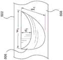
如图2C(其是小叶区域和裙部区域的简化立体图)所展示的,单件式瓣膜模型200和/250相对于单件式瓣膜模型200和/或250的平面顶表面207具有平坦轮廓或二维(2D)轮廓。当被形成为管状瓣膜子组件时,平面顶表面207的平坦轮廓形成连续的管状表面以附接至管状框架的内表面,如下文更详细地描述。当管状瓣膜子组件附接至管状框架时,由小叶区域202、204和206形成的小叶及其相应的小叶腹部230朝向管状框架的纵向轴线延伸到管状框架的内部中。这样,每个瓣膜小叶区域202、204和206的小叶腹部230被形成为相对于单件式瓣膜模型200和/或250的平面顶表面207具有三维(3D)轮廓。As shown in FIG. 2C (which is a simplified perspective view of the leaflet region and skirt region), the one-piece valve models 200 and/250 have a flat profile or profile relative to the planartop surface 207 of the one-piece valve models 200 and/or 250. Two-dimensional (2D) contours. When formed as a tubular valve subassembly, the flat profile of the planartop surface 207 forms a continuous tubular surface for attachment to the inner surface of the tubular frame, as described in more detail below. When the tubular valve subassembly is attached to the tubular frame, the leaflets formed byleaflet regions 202, 204, and 206 and theircorresponding leaflet abdomens 230 extend into the interior of the tubular frame toward the longitudinal axis of the tubular frame. In this manner, theleaflet belly 230 of eachvalve leaflet region 202 , 204 , and 206 is formed to have a three-dimensional (3D) contour relative to the planartop surface 207 of the one-piece valve model 200 and/or 250 .

例如,如图2D(其是小叶区域202的放大立体图)所展示的,小叶腹部230被形成为具有3D半钟形或抛物面形状。小叶腹部230的3D抛物面形状的尺寸可以由最大宽度w1、最大长度ll和最大深度d1来限定。这些尺寸可以取决于心脏瓣膜假体(包括单件式瓣膜模型200和/250)的大小,例如,23毫米(mm)的心脏瓣膜假体、26mm的心脏瓣膜假体、29mm的心脏瓣膜假体、34mm的心脏瓣膜假体等。例如,在29mm的心脏瓣膜假体中,小叶腹部230的尺寸可以包括:大致为22mm的最大宽度w1、大致为16mm的最大长度ll、大致为5mm的最大深度d1。本领域技术人员将认识到,本文描述的尺寸的任何示例都是近似值并且可以基于制造公差、操作条件和/或其他因素变化例如+/-5.0%。For example, as illustrated in FIG. 2D , which is an enlarged perspective view ofleaflet region 202 , leaflet abdomen 230 is formed to have a 3D half-bell or parabolic shape. The dimensions of the 3D parabolic shape of theleaflet abdomen 230 may be defined by a maximum width w1 , a maximum length ll , and a maximum depth d1 . These dimensions may depend on the size of the heart valve prosthesis (including one-piece valve models 200 and /250), for example, a 23 millimeter (mm) heart valve prosthesis, a 26 mm heart valve prosthesis, a 29 mm heart valve prosthesis , 34mm heart valve prosthesis, etc. For example, in a 29mm heart valve prosthesis, the dimensions of theleaflet belly 230 may include a maximum width w1 of approximately 22mm, a maximum length ll of approximately 16mm, and a maximum depth d1 of approximately 5mm. Those skilled in the art will recognize that any examples of dimensions described herein are approximations and may vary, eg, +/- 5.0%, based on manufacturing tolerances, operating conditions, and/or other factors.

如上文所讨论的,当切割单件式瓣膜模型200和/或250时,将瓣膜材料112平坦片110在工作表面102上展开,例如,平放。由于每个小叶区域202、204、206的小叶腹部230需要被形成为具有3D形状,因此在用切割设备108切割之前需要将额外的材料聚集在小叶区域202、204、206中。在实施例中,如图2E(其是小叶区域202的简化视图)所展示的,通过在小叶区域202、204、206中形成瓣膜材料112的三角形褶皱或折痕290(以下称为三角形折痕),可以将额外的瓣膜材料112聚集在小叶区域202、204、206中。在实施例中,三角形折痕290包括已经相对于瓣膜材料112平坦片110聚集的额外的材料。在实施例中,如图2E所展示的,三角形折痕290具有三角形形状,使得邻近于附接边沿232的宽度w2大于邻近于小叶区域202、204、206的中心的宽度w3。这样,聚集在三角形折痕290中的瓣膜材料的量从附接边沿232到小叶腹部230的中心减少。例如,三角形折痕290的尺寸可以包括范围从大致1mm至大致2mm的宽度w2和范围从大致0.1mm至大致0.2mm的宽度w3As discussed above, when cutting the one-piece valve models 200 and/or 250, theflat sheet 110 ofvalve material 112 is spread out, eg, lays flat, on the workingsurface 102 . Since theleaflet abdomen 230 of eachleaflet region 202 , 204 , 206 needs to be formed to have a 3D shape, additional material needs to be gathered in theleaflet region 202 , 204 , 206 prior to cutting with thecutting device 108 . In an embodiment, as illustrated in FIG. 2E (which is a simplified view of the leaflet region 202), thevalve material 112 is formed by forming triangular folds or creases 290 (hereinafter referred to as triangular creases) in theleaflet regions 202, 204, 206. ),additional valve material 112 may be gathered in theleaflet regions 202, 204, 206. In an embodiment, thetriangular fold 290 includes additional material that has gathered relative to theflat sheet 110 ofvalve material 112 . In an embodiment, as shown in FIG. 2E ,triangular fold 290 hasa triangular shape such that width w 2adjacent attachment edge 232 is greater than width w3 adjacent the centers ofleaflet regions 202 , 204 , 206 . In this way, the amount of valve material that collects in thetriangular fold 290 decreases from theattachment edge 232 to the center of theleaflet abdomen 230 . For example, dimensions oftriangular crease 290 may include a width w2 ranging from approximately 1 mm to approximately 2 mm and a width w3 ranging from approximately 0.1 mm to approximately 0.2 mm.

在一些实施例中,三角形折痕290可以通过将瓣膜材料112缝制成褶皱、例如用缝合线将瓣膜材料112在瓣膜小叶区域202、204、206中收紧形成褶皱,以在每个瓣膜小叶区域202、204、206中形成三角形折痕290来形成。在一些实施例中,三角形折痕290可以在用切割设备108切割单件式瓣膜模型200和/或250之前使用折叠设备104来形成。In some embodiments, thetriangular crease 290 may be formed by sewing thevalve material 112 into a fold, such as by tightening thevalve material 112 with sutures in thevalve leaflet regions 202, 204, 206 to form a fold in each valve leaflet.Triangular creases 290 are formed inregions 202, 204, 206 to form. In some embodiments,triangular fold 290 may be formed usingfolding device 104 prior to cutting single-piece valve model 200 and/or 250 with cuttingdevice 108 .

图3A至图3C是根据本文实施例的折叠装置300的几个视图。本领域技术人员将意识到,图3A至图3C展示了折叠装置的一个示例,并且图3A至图3C展示的现有部件可以被移除,和/或可以对折叠装置300添加额外的部件。3A-3C are several views of afolding device 300 according to embodiments herein. Those skilled in the art will appreciate that FIGS. 3A-3C illustrate one example of a folding device and that existing components shown in FIGS. 3A-3C may be removed and/or additional components may be added tofolding device 300 .

如图3A所展示的,折叠装置300包括u形环302和附接至u形环302的外表面305的臂304。相邻的一对臂304限定了折叠空间306,三角形折痕290可以在该折叠空间中形成。即,相邻的成对的臂304相对于彼此以角度θ10从u形环302向外延伸。折叠装置300可以包括多对相邻的臂304,其数量对应于要在小叶区域202、204、206中形成的三角形折痕290的数量。As illustrated in FIG. 3A , thefolding device 300 includes a u-ring 302 and anarm 304 attached to anouter surface 305 of the u-ring 302 . Adjacent pairs ofarms 304 define afold space 306 in whichtriangular fold 290 may be formed. That is, adjacent pairs ofarms 304 extend outwardly fromu-shaped ring 302 at an angle θ10 relative to each other. Thefolding device 300 may include a number of pairs ofadjacent arms 304 corresponding to the number oftriangular folds 290 to be formed in theleaflet regions 202 , 204 , 206 .

如图3B(其是相邻的一对臂304的放大立体图)所展示的,臂304相对于彼此以角度θ10从u形环302的外表面305向外延伸。臂304可以被形成为具有从与u形环302的外表面305的连接部到臂304的端部310的长度l10。在一些实施例中,长度l10可以对应于三角形折痕290的近似长度。长度l10可以取决于由小叶区域202、204、206形成的小叶的大小。例如,臂304可以被形成为具有范围从大致10mm至大致16mm的长度l10As shown in FIG. 3B , which is an enlarged perspective view of an adjacent pair ofarms 304 , thearms 304 extend outwardly from theouter surface 305 of theu-shaped ring 302 at an angle θ10 relative to each other. Thearm 304 may be formed to have a length l10 from the connection with theouter surface 305 of the u-ring 302 to theend 310 of thearm 304 . In some embodiments, length l10 may correspond to the approximate length oftriangular crease 290 . The length l10 may depend on the size of the leaflet formed by theleaflet regions 202 , 204 , 206 . For example,arm 304 may be formed to have a length l10 ranging from approximately 10 mm to approximately 16 mm.

每个臂304包括联接至臂304的端部310的夹具320。夹具320可以由提供相对于臂304更高摩擦系数的材料构成。在实施例中,夹具320可以在臂304的面向折叠空间306的内表面322上从臂304的端部310延伸。这样,当臂304朝向彼此向内偏置时,夹具320可以操作来夹握被定位在折叠空间306中的瓣膜材料。Eacharm 304 includes aclamp 320 coupled to theend 310 of thearm 304 .Clamp 320 may be constructed of a material that provides a higher coefficient of friction relative toarm 304 . In an embodiment, theclip 320 may extend from theend 310 of thearm 304 on aninner surface 322 of thearm 304 facing thefold space 306 . As such, whenarms 304 are biased inwardly toward each other,gripper 320 is operable to grip valve material positioned infold space 306 .

臂304适合地由准许臂304分开、朝向彼此向内偏置的弹性材料构成。例如,臂304可以由柔性金属、柔性金属合金、柔性聚合物材料、形状记忆金属合金(例如,镍钛合金)等构成。夹具320操作来使臂304在端部310处偏置在一起以将瓣膜材料捕获、夹紧和/或固持在其间。在实施例中,偏置构件330可以联接至臂304。偏置构件330可以被配置为对臂304施加力以使臂朝向彼此向内偏置,从而减小折叠空间306。例如,偏置构件330可以包括联接在臂304与u形环302之间的一个或多个弹簧。弹簧可以对臂304施加向内朝向折叠空间306的力,从而使臂304对定位在折叠空间306中的瓣膜材料施加力。Thearms 304 are suitably constructed of a resilient material that permits thearms 304 to separate, biased inwardly towards each other. For example, thearm 304 may be constructed of a flexible metal, a flexible metal alloy, a flexible polymer material, a shape memory metal alloy (eg, Nitinol), or the like.Clamp 320 operates to biasarms 304 together at ends 310 to capture, clamp and/or hold valve material therebetween. In an embodiment, a biasingmember 330 may be coupled to thearm 304 .Biasing member 330 may be configured to apply a force toarms 304 to bias the arms inwardly toward each other, thereby reducingfold space 306 . For example, biasingmember 330 may include one or more springs coupled betweenarm 304 andu-ring 302 . The spring may force thearms 304 inwardly toward thefold space 306 , causing thearms 304 to exert a force on the valve material positioned in thefold space 306 .

如图3B进一步所展示的,为了创建三角形折痕290,可以将折叠装置300放在瓣膜材料112平坦片110的顶表面上。然后,可以将瓣膜材料110向上拉动穿过由每对相邻的臂304形成的每个折叠空间306。由于相邻的成对的臂304相对于彼此成角度θ10定位,因此在端部310处更多的材料被向上拉动穿过折叠空间306,从而形成三角形折痕290。然后,相邻的成对的臂304的夹具320朝向彼此向内偏置以在用切割设备108进行切割期间将额外的瓣膜材料112夹紧、夹住和/或固持。As further illustrated in FIG. 3B , to createtriangular fold 290 ,folding device 300 may be placed on the top surface offlat sheet 110 ofvalve material 112 . Thevalve material 110 can then be pulled up through eachfold space 306 formed by each pair ofadjacent arms 304 . Because adjacent pairs ofarms 304 are positioned at an angle θ10 relative to each other, more material is drawn up throughfold space 306 atend 310 , formingtriangular fold 290 . Theclamps 320 of adjacent pairs ofarms 304 are then biased inwardly toward each other to clamp, clamp and/or hold theadditional valve material 112 during cutting with thecutting device 108 .

在实施例中,瓣膜制造系统100的折叠设备104可以包括与单件式瓣膜模型中所包含的小叶区域的数量相对应的多个折叠装置300。例如,如图3C所展示的,折叠设备104可以包括三个折叠装置300,用于在单件式瓣膜模型200和/或250中创建三角形折痕290。在折叠设备104中,折叠装置300可以联接至间隔杆350。折叠装置300可以相对于彼此以距离d10联接至间隔杆350。在一些实施例中,距离d10可以对应于单件式瓣膜模型200和/或250中的小叶区域202、204、206的间隔距离。例如,d距离d10可以对应于沿着间隔杆350测量的、相邻折叠装置300的中点相距的线性距离。距离d10可以被选择为使得当瓣膜材料112平坦片110放在工作表面102上时折叠装置300与小叶区域202、204、206对准。In an embodiment, thefolding apparatus 104 of thevalve manufacturing system 100 may include a number offolding devices 300 corresponding to the number of leaflet regions contained in the single-piece valve model. For example, as illustrated in FIG. 3C ,folding apparatus 104 may include threefolding devices 300 for creatingtriangular folds 290 in single-piece valve models 200 and/or 250 . In thefolding apparatus 104 , thefolding device 300 may be coupled to aspacer bar 350 . Thefolding device 300 may be coupled to thespacer bar 350 at a distance d10 relative to each other. In some embodiments, distance d10 may correspond to the separation distance ofleaflet regions 202 , 204 , 206 in one-piece valve model 200 and/or 250 . For example, the d-distance d10 may correspond to the linear distance between the midpoints of adjacentfolding devices 300 as measured along thespacer bar 350 . Distance d10 may be selected such thatfolding device 300 is aligned withleaflet regions 202 , 204 , 206 whenflat sheet 110 ofvalve material 112 is placed on workingsurface 102 .

图4A至图4C是根据本文实施例的折叠装置400的几个视图。本领域技术人员将意识到,图4A至图4C展示了折叠装置的一个示例,并且图4A至图4C展示的现有部件可以被移除,和/或可以对折叠装置400添加额外的部件。4A-4C are several views of afolding device 400 according to embodiments herein. Those skilled in the art will appreciate that FIGS. 4A-4C illustrate one example of a folding device and that existing components shown in FIGS. 4A-4C may be removed and/or additional components may be added tofolding device 400 .

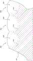
如图4A所展示的,折叠装置400包括u形本体402和从u形本体402向外延伸的固定接片(或组块)404。固定接片404提供可以用于在瓣膜材料112平坦片110中创建折痕的刚性或半刚性结构。在一些实施例中,固定接片404可以是附接(可移除地或永久地)至u形本体402的单独结构。在一些实施例中,固定接片404和u形本体404可以被构造为单一一体式结构。As shown in FIG. 4A , thefolding device 400 includes au-shaped body 402 and a fixing tab (or block) 404 extending outward from theu-shaped body 402 . Thefixation tabs 404 provide a rigid or semi-rigid structure that can be used to create a crease in theflat sheet 110 ofvalve material 112 . In some embodiments, the securingtab 404 may be a separate structure attached (removably or permanently) to theu-shaped body 402 . In some embodiments, the securingtab 404 and theu-shaped body 404 may be constructed as a single, unitary structure.

相邻的一对固定接片404限定了折叠空间406,三角形折痕290可以在该折叠空间中形成。即,相邻的成对的固定接片404相对于彼此以角度θ20从u形本体402向外延伸。折叠装置400可以包括多对相邻的固定接片404,其数量对应于要在小叶区域202、204、206中形成的三角形折痕290的数量。Adjacent pairs of securingtabs 404 define afold space 406 in which atriangular fold 290 may be formed. That is, adjacent pairs of securingtabs 404 extend outwardly fromu-shaped body 402 at an angleθ20 relative to each other. Thefolding device 400 may include a number of adjacent pairs offixation tabs 404 corresponding to the number oftriangular folds 290 to be formed in theleaflet regions 202 , 204 , 206 .

如图4B(其是相邻的一对固定接片404的放大立体图)所展示的,固定接片404相对于彼此以角度θ20从u形本体402向外延伸。固定接片404可以被形成为具有以从与u形本体402的连接部延伸到固定接片404的端部410的长度l20。固定接片404可以被形成为具有高度H20。在一些实施例中,长度l20可以对应于三角形折痕290的近似长度。固定接片404的尺寸可以取决于由小叶区域202、204、206形成的小叶的大小。例如,固定接片404可以被形成为具有范围从大致5mm至大致20mm(例如,10mm)的长度l20。固定接片404可以由刚性材料构造,以在瓣膜材料被拉动穿过折叠空间406时允许固定接片404保持固定。例如,固定接片404可以由刚性金属、刚性金属合金、刚性聚合材料等构造。As shown in FIG. 4B , which is an enlarged perspective view of an adjacent pair of securingtabs 404 , the securingtabs 404 extend outwardly from theu-shaped body 402 at an angleθ20 relative to each other. The securingtab 404 may be formed to have a length l20 extending from the connection with theu-shaped body 402 to theend 410 of the securingtab 404 .Fixed tab 404 may be formed to have a height H20 . In some embodiments, length l20 may correspond to the approximate length oftriangular crease 290 . The size of thefixation tab 404 may depend on the size of the leaflet formed by theleaflet regions 202 , 204 , 206 . For example, the securingtab 404 may be formed to have a length l20 ranging from approximately 5 mm to approximately 20 mm (eg, 10 mm). Thefixation tabs 404 may be constructed of a rigid material to allow thefixation tabs 404 to remain fixed as the valve material is pulled through thefold space 406 . For example, securingtab 404 may be constructed from a rigid metal, rigid metal alloy, rigid polymeric material, or the like.

在实施例中,固定接片404的、面向折叠空间406的内表面420的一部分可以包括和/或涂覆有提供相对于固定接片404更高摩擦系数的材料。这样,内表面420一部分上的材料可以操作来夹握被定位在折叠空间406中的瓣膜材料。In an embodiment, a portion of theinterior surface 420 of the securingtab 404 that faces thefold space 406 may include and/or be coated with a material that provides a higher coefficient of friction relative to thesecuring tab 404 . As such, material on a portion ofinner surface 420 is operable to grip valve material positioned infold space 406 .

为了创建三角形折痕290,可以将折叠装置400放在瓣膜材料112平坦片110的顶部上,如图4B进一步所展示的。然后,可以将瓣膜材料112向上拉动穿过由每对相邻的固定接片404形成的每个折叠空间406。由于相邻的成对的固定接片404相对于彼此成角度θ20定位,因此在端部410处更多的材料被向上拉动穿过折叠空间406,从而形成三角形折痕290。To createtriangular crease 290,folding device 400 may be placed on top offlat sheet 110 ofvalve material 112, as further illustrated in FIG. 4B. Thevalve material 112 can then be pulled up through eachfold space 406 formed by each pair ofadjacent fixation tabs 404 . Due to the positioning of adjacent pairs of securingtabs 404 relative to each other at an angleθ20 , more material is drawn upwardly throughfold space 406 atend 410 , formingtriangular fold 290 .

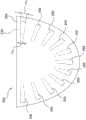
在实施例中,瓣膜制造系统100的折叠设备104可以包括与单件式瓣膜模型中所包含的小叶区域的数量相对应的多个折叠装置400。例如,如图4C所展示的,折叠设备104可以包括三个折叠装置400,用于在单件式瓣膜模型200和/或250中创建三角形折痕290。在折叠设备104中,折叠装置400可以联接至间隔杆450。折叠装置400可以相对于彼此以距离d20联接至间隔杆450。在一些实施例中,距离d20可以对应于单件式瓣膜模型200和/或250中的小叶区域202、204、206的间隔距离。例如,d距离d20可以对应于沿着间隔杆450测量的、相邻折叠装置400的中点相距的线性距离。距离d20可以被选择为使得当瓣膜材料112平坦片110放在工作表面102上时折叠装置400与小叶区域202、204、206对准。In an embodiment, thefolding apparatus 104 of thevalve manufacturing system 100 may include a number offolding devices 400 corresponding to the number of leaflet regions contained in the single-piece valve model. For example, as illustrated in FIG. 4C ,folding apparatus 104 may include threefolding devices 400 for creatingtriangular folds 290 in single-piece valve models 200 and/or 250 . In thefolding apparatus 104 , thefolding device 400 may be coupled to aspacer bar 450 . Thefolding device 400 may be coupled to thespacer bar 450 at a distance d20 relative to each other. In some embodiments, distance d20 may correspond to the separation distance ofleaflet regions 202 , 204 , 206 in one-piece valve model 200 and/or 250 . For example, the d-distance d20 may correspond to the linear distance between the midpoints of adjacentfolding devices 400 as measured along thespacer bar 450 . Distance d20 may be selected such thatfolding device 400 is aligned withleaflet regions 202 , 204 , 206 whenflat sheet 110 ofvalve material 112 is placed on workingsurface 102 .

虽然折叠装置300和400在上文中被描述为操作来创建三角形折痕290,但是本领域的技术人员将认识到,折痕290的三角形形状是折痕290的形状的一个示例。在实施例中,折痕290可以基于小叶区域202、204、206的期望形状被创建具有不同的形状。Althoughfolding devices 300 and 400 are described above as operating to createtriangular crease 290 , those skilled in the art will recognize that the triangular shape ofcrease 290 is one example of a shape forcrease 290 . In embodiments,crease 290 may be created with different shapes based on the desired shape ofleaflet regions 202 , 204 , 206 .

图5A至图5C展示了根据本文实施例的用于形成瓣膜结构的小叶腹部的模制设备106。本领域技术人员将意识到,图5A至图5C展示了模制设备的一个示例,并且图5A至图5C展示的现有部件可以被移除,和/或可以对模制设备106添加额外的部件。5A-5C illustrate amolding apparatus 106 for forming the leaflet belly of a valve structure, according to embodiments herein. Those skilled in the art will appreciate that FIGS. 5A-5C illustrate one example of a molding apparatus and that existing components shown in FIGS. 5A-5C may be removed and/or additional components may be added tomolding apparatus 106. part.

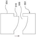
如图5A所展示的,模制设备106包括底部模具502和顶部模具504。底部模具502包括形成在底部模具502的顶表面508中的多个凹陷506。例如,对于单件式瓣膜模型200和/或250,底部模具502可以包括三个凹陷506。每个凹陷506被构造为具有小叶腹部230的3D形状。如上文所讨论的,每个瓣膜小叶区域202、204和206的小叶腹部230被形成为相对于单件式瓣膜模型200和/或250的平面顶表面270具有3D轮廓(形状)。例如,如上图2D所展示的,小叶腹部230可以被形成为具有3D半钟形或抛物面形状。如图5B(其是凹陷506的放大视图)所展示的,凹陷506可以具有与小叶腹部230的期望3D形状相对应的3D半钟形或抛物面形状。凹陷506被构造为具有与小叶腹部230的期望尺寸相对应的尺寸。例如,如图5B所展示的,凹陷506的尺寸可以由最大宽度w1、最大长度ll、和最大深度d1来限定。As shown in FIG. 5A , themolding apparatus 106 includes abottom mold 502 and atop mold 504 .Bottom mold 502 includes a plurality ofdepressions 506 formed in atop surface 508 ofbottom mold 502 . For example, for one-piece valve models 200 and/or 250 ,bottom mold 502 may include threedepressions 506 . Eachdepression 506 is configured to have the 3D shape of theleaflet abdomen 230 . As discussed above, theleaflet belly 230 of eachvalve leaflet region 202 , 204 , and 206 is formed to have a 3D profile (shape) relative to the planartop surface 270 of the one-piece valve model 200 and/or 250 . For example, as illustrated in FIG. 2D above, theleaflet abdomen 230 may be formed to have a 3D half-bell or parabolic shape. As illustrated in FIG. 5B , which is an enlarged view of thedepression 506 , thedepression 506 may have a 3D half-bell or parabolic shape corresponding to the desired 3D shape of theleaflet abdomen 230 . Thedepression 506 is configured to have a size corresponding to the desired size of theleaflet abdomen 230 . For example, as illustrated in FIG. 5B , the dimensions of therecess 506 may be defined by a maximum width w1 , a maximum length ll , and a maximum depth d1 .

顶部模具504包括从顶部模具的底表面512延伸的多个突出部510。如图5C(其是沿着图5A的线A-A截取的截面视图)所展示的,每个突出部510具有与凹陷506的形状配合的3D形状并且位于顶表面512上、与凹陷506的位置相对应。在操作期间,底部模具502和顶部模具504被放在一起以压缩在配合的凹陷/模制表面506与突出部/模制表面510之间的瓣膜材料,从而形成3D形状的小叶腹部230。这样,每个突出部510被构造为具有小于对应凹陷506的尺寸的尺寸,从而允许每个突出部510装配在对应凹陷506内。下文在制造假体心脏瓣膜的方法的描述中更详细地讨论了模制设备106的进一步操作。Thetop mold 504 includes a plurality ofprotrusions 510 extending from a bottom surface 512 of the top mold. 5C (which is a cross-sectional view taken along line A-A of FIG. 5A ), eachprotrusion 510 has a 3D shape that fits the shape of therecess 506 and is located on the top surface 512 at the same location as therecess 506. correspond. During operation, thebottom mold 502 andtop mold 504 are brought together to compress the valve material between the cooperating recessed/moldedsurface 506 and protrusion/moldedsurface 510 to form the 3D shapedleaflet belly 230 . In this manner, eachprotrusion 510 is configured to have a size that is smaller than the size of thecorresponding recess 506 , thereby allowing eachprotrusion 510 to fit within thecorresponding recess 506 . Further operations of themolding apparatus 106 are discussed in more detail below in the description of the method of manufacturing a prosthetic heart valve.

如上所述,凹陷506和突出部510被设计成形成小叶腹部230,小叶腹部的大小和形状基本上类似于对应功能的自体心脏瓣膜。例如,凹陷506和突出部510的大小、形状和位置被设计为提供小叶腹部230,小叶腹部在组装时形成小叶,小叶的大小和形状将被理想地设计成使得它们在瓣膜关闭时彼此接触以确保恰当的瓣膜关闭。在实施例中,可以提供不同大小的凹部506和突出部510以适应具有不同心脏瓣膜根环尺寸的患者的解剖结构。在一些实施例中,模制设备106可以包括具有相同大小和形状或不同大小和形状的凹陷506和突出部510。在一些实施例中,模制设备106可以包括被制作来提供针对特定患者设计的心脏瓣膜的凹陷506和突出部510。As noted above, thedepressions 506 andprotrusions 510 are designed to form theleaflet belly 230, which is substantially similar in size and shape to a corresponding functional native heart valve. For example, the size, shape and location of therecess 506 andprotrusion 510 are designed to provide theleaflet abdomen 230, which when assembled forms the leaflets, which will ideally be sized and shaped so that they contact each other when the valve closes to form the leaflets. Ensure proper valve closure. In an embodiment, differentsized recesses 506 andprotrusions 510 may be provided to accommodate the anatomy of patients with different heart valve root annulus sizes. In some embodiments,molding device 106 may includerecesses 506 andprotrusions 510 having the same size and shape or different sizes and shapes. In some embodiments,molding device 106 may includerecesses 506 andprotrusions 510 that are fabricated to provide a patient-specific designed heart valve.

虽然模制设备106被描述为具有带凹陷506的底部模具502和带突出部510的顶部模具504,但是本领域技术人员将认识到,顶部和底部的使用是相对的术语。在一些实施例中,底部模具502可以包括突出部510,而顶部模具504可以包括凹陷506。While themolding apparatus 106 is described as having abottom mold 502 with arecess 506 and atop mold 504 with aprotrusion 510, those skilled in the art will recognize that the use of top and bottom are relative terms. In some embodiments,bottom mold 502 may includeprotrusions 510 andtop mold 504 may includedepressions 506 .

图6和图7A至图7E展示了根据本文实施例的用于制造假体心脏瓣膜的方法600的示例。本领域的技术人员将意识到,图6和图7A至图7E展示了使用制造系统100的方法的一个示例,并且图6展示的现有操作可以被移除,和/或可以对方法600添加额外的操作。6 and 7A-7E illustrate an example of amethod 600 for fabricating a prosthetic heart valve according to embodiments herein. Those skilled in the art will appreciate that FIGS. 6 and 7A-7E illustrate one example of a method of usingmanufacturing system 100, and that existing operations illustrated in FIG. 6 may be removed, and/or additions may be made tomethod 600. additional operations.

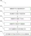
在步骤602中,将瓣膜材料平坦片布置在工作表面上。例如,如上图1所展示的,瓣膜材料112平坦片110可以放置和布置成基本上平坦地在工作表面102的顶表面区域103上。Instep 602, a flat sheet of valve material is placed on a working surface. For example, as illustrated above in FIG. 1 , theflat sheet 110 ofvalve material 112 may be placed and arranged substantially flat on thetop surface region 103 of the workingsurface 102 .

在步骤604中,在瓣膜材料平坦片中在瓣膜小叶区域中创建折痕。在实施例中,一旦将瓣膜材料112平坦片110放在工作表面102上,则在用切割设备108进行切割之前,需要将为了形成腹部区域230所需的额外材料聚集在小叶区域202、204、206中。通过在小叶区域202、204、206中形成瓣膜材料112的三角形折痕290,可以将额外的瓣膜材料112聚集在小叶区域202、204、206中,如上图2E中所展示的。三角形折痕290可以被形成为具有三角形形状,使得邻近于附接边沿232的宽度w2大于邻近于小叶区域202、204、206的中心的宽度w3Instep 604, creases are created in the valve leaflet region in the flat sheet of valve material. In an embodiment, once theflat sheet 110 ofvalve material 112 is placed on the workingsurface 102, additional material needed to form theabdominal region 230 needs to be gathered in theleaflet regions 202, 204, 206 in.Additional valve material 112 may be gathered in theleaflet regions 202, 204, 206 by formingtriangular folds 290 of thevalve material 112 in theleaflet regions 202, 204, 206, as illustrated in Figure 2E above.Triangular crease 290 may be formed to have a triangular shape such that width w2adjacent attachment edge 232 is greater than width w3 adjacent the center ofleaflet regions 202 , 204 , 206 .

在一些实施例中,三角形折痕290可以通过将瓣膜材料112缝制成褶皱以在每个瓣膜小叶区域202、204、206中形成三角形折痕290来形成。例如,三角形折痕290可以手工缝入瓣膜小叶区域202、204和206中。In some embodiments,triangular crease 290 may be formed bysewing valve material 112 into folds to formtriangular crease 290 in eachvalve leaflet region 202 , 204 , 206 . For example, triangular folds 290 may be hand sewn intovalve leaflet regions 202, 204, and 206.

在一些实施例中,三角形折痕290可以在用切割设备108切割单件式瓣膜模型200和/或250之前使用折叠设备104来形成。例如,可以将包括折叠装置300的折叠设备104放在瓣膜材料112平坦片110上并且布置在瓣膜小叶区域202、204和206中。然后,一旦布置好,就可以将瓣膜材料110向上拉动穿过由每对相邻的臂304形成的每个折叠空间306,从而在臂之间夹成三角形折褶290。在用切割设备108进行切割期间,可以将额外的瓣膜材料112固持在臂304内。In some embodiments,triangular fold 290 may be formed usingfolding device 104 prior to cutting single-piece valve model 200 and/or 250 with cuttingdevice 108 . For example,folding device 104 includingfolding device 300 may be placed onflat sheet 110 ofvalve material 112 and disposed invalve leaflet regions 202 , 204 and 206 . Then, once deployed, thevalve material 110 can be pulled up through eachfold space 306 formed by each pair ofadjacent arms 304, sandwiching atriangular fold 290 between the arms.Additional valve material 112 may be retained withinarms 304 during cutting with cuttingdevice 108 .

同样,例如,可以将包括折叠装置400的折叠设备104放在瓣膜材料112平坦片110(其搁置在工作表面102上)上并且布置在瓣膜小叶区域202、204和206中。然后,一旦布置好,就可以将瓣膜材料110拉动穿过由每对相邻的固定接片404形成的每个折叠空间406,从而形成三角形折痕290。Also, for example,folding device 104 includingfolding device 400 may be placed onflat sheet 110 ofvalve material 112 resting on workingsurface 102 and disposed invalve leaflet regions 202, 204, and 206. Then, once deployed, thevalve material 110 can be pulled through eachfold space 406 formed by each adjacent pair offixation tabs 404 to form thetriangular fold 290 .

在步骤606中,将瓣膜材料平坦片切割成单件式瓣膜模型。在实施例中,可以激活切割设备108来切割单件式瓣膜模型,比如单件式瓣膜模型200和/或250。由于瓣膜小叶区域202、204和206包括三角形折痕290,因此单件式瓣膜模型200和/或250包括为了形成小叶腹部230所需的额外的瓣膜材料112。一旦切割出单件式瓣膜模型200和/或250,就可以将折叠设备104(如果使用的话)从单件式瓣膜模型200和/或250移除。同样地,如果是缝出三角形折痕290,则可以将缝线从单件式瓣膜模型200和/或250移除。Instep 606, the flat sheet of valve material is cut into a one-piece valve model. In an embodiment, cuttingdevice 108 may be activated to cut a one-piece valve model, such as one-piece valve model 200 and/or 250 . Becausevalve leaflet regions 202 , 204 , and 206 includetriangular folds 290 , one-piece valve models 200 and/or 250 includeadditional valve material 112 required to formleaflet belly 230 . Once the single-piece valve model 200 and/or 250 is cut, the folding device 104 (if used) can be removed from the single-piece valve model 200 and/or 250 . Likewise, iftriangular fold 290 is sewn, the sutures may be removed from one-piece valve model 200 and/or 250 .

在步骤608中,将瓣膜小叶区域布置在模制设备中。模制设备106操作来将由三角形折痕290形成的额外的瓣膜材料112成形为小叶腹部230。如图7A所展示的,底部模具502和顶部模具504可以是分开的,从而露出凹陷506和突出部510。可以将单件式瓣膜模型200和/或250布置在模制设备106中,使得瓣膜小叶区域202、204、206在相应的凹陷506与其配合的突出部510之间对准。例如,可以将瓣膜小叶区域202、204、206中的每一个布置在相应的凹陷506内。一旦布置好,就将底部模具502和顶部模具504带到一起,从而将瓣膜小叶区域202、204、206捕捉在凹陷506与突出部510之间。Instep 608, the valve leaflet region is placed in the molding apparatus. Themolding apparatus 106 operates to shape theadditional valve material 112 formed by the triangular folds 290 into theleaflet belly 230 . As illustrated in FIG. 7A ,bottom mold 502 andtop mold 504 may be separated, exposingrecesses 506 andprotrusions 510 . The one-piece valve formers 200 and/or 250 may be arranged in themolding apparatus 106 such that thevalve leaflet regions 202 , 204 , 206 are aligned betweenrespective recesses 506 and their cooperatingprotrusions 510 . For example, each of thevalve leaflet regions 202 , 204 , 206 may be disposed within acorresponding recess 506 . Once deployed, thebottom mold 502 andtop mold 504 are brought together, capturing thevalve leaflet regions 202 , 204 , 206 between thedepressions 506 andprotrusions 510 .

在步骤610中,固定每个瓣膜小叶区域的小叶腹部的形状。在实施例中,为了固定小叶腹部230的形状,对模制设备106引入固定剂。例如,在底部模具502与顶部模具504之间夹有单件式瓣膜模型200和/或250的模制设备106浸没在固定溶液(比如具有戊二醛的溶液)中,以使组织交联。交联方法和溶液是本领域熟知的。在浸没在固定溶液期间,溶液渗透过凹陷506以使组织交联。然后,将模制设备106从固定溶液中移除并漂洗。Instep 610, the shape of the leaflet belly of each valve leaflet area is fixed. In an embodiment, to fix the shape of theleaflet abdomen 230 , a fixative is introduced to themolding device 106 . For example,molding device 106 with one-piece valve former 200 and/or 250 sandwiched betweenbottom mold 502 andtop mold 504 is submerged in a fixative solution, such as a solution with glutaraldehyde, to crosslink the tissue. Crosslinking methods and solutions are well known in the art. During immersion in the fixative solution, the solution permeates through thedepressions 506 to crosslink the tissue. Themolding device 106 is then removed from the fixative solution and rinsed.

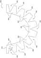
在步骤612中,用单件式瓣膜模型来形成管状瓣膜子组件。在实施例中,管状瓣膜子组件是通过将单件式瓣膜模型200和/或250形成为管状结构而形成的。例如,如图7B所展示的,可以将单件式瓣膜模型200和/或250的纵向边缘270和272以配合或邻接的关系带到一起。如图7C所展示的,一旦配合,则可以创建从单件式瓣膜模型200和/或250的第一端276延伸至单件式瓣膜模型200和/或250的第二端278的侧缝274,从而将纵向边缘270和272连结并形成管状瓣膜子组件700。在实施例中,侧缝274是用缝合线或其他细丝手工缝制的。Instep 612, the one-piece valve mold is used to form a tubular valve subassembly. In an embodiment, the tubular valve subassembly is formed by forming the one-piece valve former 200 and/or 250 into a tubular structure. For example, as illustrated in Figure 7B, thelongitudinal edges 270 and 272 of the one-piece valve models 200 and/or 250 may be brought together in a mating or abutting relationship. As shown in FIG. 7C , once mated, aside seam 274 extending from afirst end 276 of the one-piece valve model 200 and/or 250 to asecond end 278 of the one-piece valve model 200 and/or 250 can be created. , thereby joining thelongitudinal edges 270 and 272 and forming thetubular valve subassembly 700 . In an embodiment, the side seams 274 are hand sewn with sutures or other filaments.

如图7A和图7B所展示的,在一些实施例中,单件式瓣膜模型200和/或250可以包括耳部295,这些耳部定位在小叶区域202、204、206之间的合缝296处并且从单件式瓣膜模型200和/或250的第一端276延伸。在一些实施例中,耳部296可以在构造单件式瓣膜模型200和250时形成,例如在步骤606中从瓣膜材料112平坦片110激光切割而成。在一些实施例中,耳部296可以在步骤606之后的任何点单独地形成并且例如通过缝合线附接至单件式瓣膜模型200和250。在一些实施例中,可以省去耳部296,如图7D所展示的。As illustrated in FIGS. 7A and 7B , in some embodiments, the one-piece valve model 200 and/or 250 can includeears 295 positioned at thecommissure 296 between theleaflet regions 202 , 204 , 206 and extend from thefirst end 276 of the one-piece valve former 200 and/or 250. In some embodiments,ears 296 may be formed during construction of one-piece valve models 200 and 250 , eg, laser cut fromflat sheet 110 ofvalve material 112 atstep 606 . In some embodiments, theears 296 may be formed separately and attached to the one-piece valve models 200 and 250 at any point afterstep 606, for example, by sutures. In some embodiments, theears 296 may be omitted, as illustrated in Figure 7D.

在实施例中,在形成完整的管状瓣膜子组件700之前或之后,可以进行额外的处理来创建、加强和/或修改完整的管状瓣膜组件700的某些方面,如图7D所展示的。在一些实施例中,例如,可以沿着附接边沿232(比如在其中的任何缝合线孔212内)加缝缝合线或其他线/细丝,以在每个小叶的下边缘处创建、划定和/或加强每个附接边沿232。在一些实施例中,例如,可以使用缝合线或其他线/细丝来折叠和缝合附接边沿232处的瓣膜材料,以在每个小叶的下边缘处创建、划定和/或加强每个附接边沿232。在一些实施例中,例如,可以使用缝合线或其他线/细丝来将额外的瓣膜材料附接至附接边沿232,以在每个小叶的下边缘处创建、划定和/或加强每个附接边沿232。In embodiments, additional processing may be performed to create, strengthen, and/or modify certain aspects of the completetubular valve assembly 700, either before or after forming the completetubular valve subassembly 700, as illustrated in FIG. 7D. In some embodiments, for example, a suture or other thread/filament may be added along attachment edge 232 (such as within anysuture hole 212 therein) to create, score, and Eachattachment edge 232 is defined and/or reinforced. In some embodiments, for example, sutures or other threads/filaments may be used to fold and sew the valve material at theattachment rim 232 to create, demarcate and/or reinforce each leaflet at its lower edge. Alip 232 is attached. In some embodiments, for example, sutures or other threads/filaments may be used to attach additional valve material toattachment rim 232 to create, demarcate and/or reinforce each leaflet at its lower edge. Anattachment edge 232.

同样地,例如,可以通过在相邻小叶之间的连结部处将缝合线或其他线/细丝缝入缝合线孔212(如果使用的话)中来加强在由瓣膜小叶区域202、204、206形成的相邻瓣膜小叶之间的连结部处创建的合缝。在一些实施例中,例如,可以通过缝入缝合线或其他线/细丝而在合缝296处添加与单件式瓣膜模型200和/或250分开形成的耳部295。管状瓣膜子组件700(如图7D所展示的)由单件式瓣膜材料形成,其限定了小叶702、704、706(由瓣膜小叶区域202、204、206及其小叶腹部230形成)、合缝296和瓣膜裙部710。Likewise, for example, thevalve leaflet regions 202, 204, 206 formed by the valve leaflets may be reinforced by sewing sutures or other threads/filaments into the suture holes 212 (if used) at the junctions between adjacent leaflets. The commissure created at the junction between the formed adjacent valve leaflets. In some embodiments,ears 295 formed separately from one-piece valve models 200 and/or 250 may be added atcommissures 296, for example, by sewing in sutures or other threads/filaments. Tubular valve subassembly 700 (as shown in FIG. 7D ) is formed from a single piece of valve material that definesleaflets 702, 704, 706 (formed byvalve leaflet regions 202, 204, 206 and their leaflet abdomen 230),commissures 296 andvalve skirt 710.

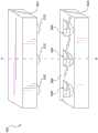
在步骤614中,将管状瓣膜子组件700附接在管状框架内以形成心脏瓣膜假体。如图7E所展示的,管状瓣膜子组件700可以经由第一端751或第二端753插入管状框架750的内部或内腔752中。一旦插入内部752中,管状瓣膜子组件700就可以使用常规的技术缝到管状框架750、例如支柱754的内表面上。例如,如果管状瓣膜子组件700包括耳部296,则耳部296可以缠绕在支柱754上并且使用缝合线或其他线/细丝固定至支架754。在上述示例中,管状瓣膜子组件700沿着管状框架750的整个长度或几乎整个长度延伸,但在其他实施例中可以延伸小于管状框架750的整个长度。多种多样的其他构造也是可接受的并且在本披露的范围内。Instep 614,tubular valve subassembly 700 is attached within a tubular frame to form a heart valve prosthesis. As shown in FIG. 7E , thetubular valve subassembly 700 can be inserted into the interior orlumen 752 of thetubular frame 750 via thefirst end 751 or thesecond end 753 . Once inserted intointerior 752,tubular valve subassembly 700 may be sewn to the inner surface oftubular frame 750, such asstruts 754, using conventional techniques. For example, iftubular valve subassembly 700 includesears 296,ears 296 may be wrapped around struts 754 and secured tobracket 754 using sutures or other wire/filament. In the examples described above, thetubular valve subassembly 700 extends along the entire length or nearly the entire length of thetubular frame 750 , but may extend less than the entire length of thetubular frame 750 in other embodiments. A wide variety of other configurations are acceptable and within the scope of this disclosure.

对于由包括外包裹区域260的单件式瓣膜模型250构造的管状瓣膜子组件700,管状瓣膜子组件700的包括瓣膜小叶区域202、204、206和裙部区域208的部分可以经由第二端753插入管状框架750的内部或内腔752中。一旦插入内部752中,管状瓣膜子组件700的包括瓣膜小叶区域202、204、206和裙部区域208的部分可以使用常规技术缝到管状框架750、例如支柱754的内表面上,如上文所讨论的。一旦固定,外包裹区域260可以折叠在第二端753上,使得管状框架750的特征可以穿过位于外包裹区域260与裙部区域208之间的附接开口242。例如,当外包裹区域260折叠在第二端753上时,管状框架750的冠部756(或如下文进一步详细描述的冠部956)可以穿过附接开口242。一旦折叠,管状瓣膜子组件700的外包裹区域260就可以使用常规技术缝到管状框架750的外表面上。Fortubular valve subassembly 700 constructed from a one-piece valve former 250 that includes overwrap region 260 , the portion oftubular valve subassembly 700 that includesvalve leaflet regions 202 , 204 , 206 andskirt region 208 may be routed viasecond end 753 . Inserted into the interior orlumen 752 of thetubular frame 750 . Once inserted intointerior 752, portions oftubular valve subassembly 700, includingvalve leaflet regions 202, 204, 206 andskirt region 208, may be sewn to the inner surface oftubular frame 750, such asstruts 754, using conventional techniques, as discussed above. of. Once secured, overwrap region 260 may be folded oversecond end 753 such that features oftubular frame 750 may pass through attachment opening 242 between overwrap region 260 andskirt region 208 . For example,crown 756 of tubular frame 750 (or crown 956 as described in further detail below) may pass through attachment opening 242 when overwrap region 260 is folded oversecond end 753 . Once folded, overwrap region 260 oftubular valve subassembly 700 may be sewn to the outer surface oftubular frame 750 using conventional techniques.

图8展示了根据本文实施例的用于制造假体心脏瓣膜的另一种方法800的示例。本领域的技术人员将意识到,图8展示了可以在制造系统100上进行的方法的一个示例,并且图8展示的现有操作可以被移除,和/或可以对方法800添加额外的操作。FIG. 8 illustrates an example of anothermethod 800 for fabricating a prosthetic heart valve according to embodiments herein. Those skilled in the art will appreciate that FIG. 8 illustrates one example of a method that may be performed onmanufacturing system 100 and that existing operations illustrated in FIG. 8 may be removed and/or additional operations may be added tomethod 800 .

在步骤802中,将瓣膜材料平坦片布置在模制设备中。在该方法中,瓣膜材料112平坦片110由可以伸展和扩张的材料(例如牛心包膜组织)构成。另外,例如,瓣膜材料112可以由聚合物、例如聚四氟乙烯(PTFE)、膨体聚四氟乙烯(E-PTFE)等构造。另外,例如,瓣膜材料112可以由制造织物、例如聚对苯二甲酸乙二醇酯(PET)等构造。另外,例如,瓣膜材料112可以由电纺材料、例如胶原蛋白、PET等构造。模制设备106操作来将瓣膜材料112的一部分成形为小叶腹部230。例如,底部模具502和顶部模具504可以是分开的,从而露出凹陷506和突出部510。可以将瓣膜材料112平坦片110布置在模制设备106中,使得未来的瓣膜小叶区域202、204、206在相应的凹陷506与突出部510之间对准。例如,可以将瓣膜小叶区域202、204、206中的每一个布置在凹陷506内。一旦布置好,就将底部模具502和顶部模具504带到一起,从而将瓣膜小叶区域202、204、和206捕捉在凹陷506与突出部510之间并且将瓣膜材料112成形为小叶腹部230的形状。Instep 802, a flat sheet of valve material is placed in a molding apparatus. In this method, aflat sheet 110 ofvalve material 112 is constructed of a material that can stretch and expand, such as bovine pericardium tissue. Also, for example,valve material 112 may be constructed from a polymer such as polytetrafluoroethylene (PTFE), expanded polytetrafluoroethylene (E-PTFE), or the like. Also, for example,valve material 112 may be constructed from a fabric, such as polyethylene terephthalate (PET), or the like. Also, for example, thevalve material 112 can be constructed from electrospun materials such as collagen, PET, and the like.Molding apparatus 106 operates to shape a portion ofvalve material 112 intoleaflet belly 230 . For example,bottom mold 502 andtop mold 504 may be separated, exposingrecesses 506 andprotrusions 510 . Theflat sheet 110 ofvalve material 112 may be arranged in themolding apparatus 106 such that the futurevalve leaflet regions 202 , 204 , 206 are aligned between therespective recesses 506 andprotrusions 510 . For example, each ofvalve leaflet regions 202 , 204 , 206 may be disposed withinrecess 506 . Once positioned, thebottom mold 502 andtop mold 504 are brought together, thereby capturing thevalve leaflet regions 202, 204, and 206 between thedepressions 506 andprotrusions 510 and forming thevalve material 112 into the shape of theleaflet abdomen 230 .

在步骤804中,固定每个瓣膜小叶区域的小叶腹部的形状。在实施例中,为了固定小叶腹部230的形状,对模制设备106引入固定溶液,比如含有戊二醛、甲醛或其他固定剂的溶液。Instep 804, the shape of the leaflet belly of each valve leaflet region is fixed. In an embodiment, to fix the shape of theleaflet abdomen 230, a fixative solution, such as a solution containing glutaraldehyde, formaldehyde, or other fixative, is introduced to themolding device 106 .

在步骤806中,将其中形成有小叶腹部的瓣膜材料片布置在工作表面上。例如,如上图1所展示的,其中形成有小叶腹部的瓣膜材料片可以放置和布置成基本上平坦地在工作表面102的顶表面区域103上。Instep 806, the sheet of valve material with the leaflet belly formed therein is placed on the working surface. For example, as illustrated in FIG. 1 above, the sheet of valve material in which the leaflet belly is formed can be placed and arranged substantially flat on thetop surface region 103 of the workingsurface 102 .

在步骤808中,将其中形成有小叶腹部的瓣膜材料片切割成单件式瓣膜模型。在实施例中,可以激活切割设备108来切割单件式瓣膜模型,比如单件式瓣膜模型200和/或250。由于瓣膜小叶区域202、204、206已经用模制设备106成形,因此瓣膜小叶区域202、204、206包括小叶腹部230。Instep 808, the sheet of valve material in which the leaflet abdomen is formed is cut into a one-piece valve model. In an embodiment, cuttingdevice 108 may be activated to cut a one-piece valve model, such as one-piece valve model 200 and/or 250 . Since thevalve leaflet regions 202 , 204 , 206 have been shaped with themolding device 106 , thevalve leaflet regions 202 , 204 , 206 include theleaflet abdomen 230 .

在步骤810中,用单件式瓣膜模型来形成管状瓣膜子组件。在步骤812中,将管状瓣膜子组件附接在管状框架内以形成心脏瓣膜假体。可以使用与上述方法600中类似的过程来形成管状瓣膜子组件并将其附接至管状框架。Instep 810, the one-piece valve former is used to form a tubular valve subassembly. Instep 812, a tubular valve subassembly is attached within a tubular frame to form a heart valve prosthesis. A process similar to that described above inmethod 600 may be used to form and attach the tubular valve subassembly to the tubular frame.

图9展示了可以与本文披露的任何实施例一起使用的管状框架900的示例。例如,管状框架900可以用作上述方法600和800中的管状框架750。本领域技术人员将意识到,图9展示了管状框架的一个示例,并且图9展示的现有部件可以被移除,和/或可以对框架900添加额外的部件。FIG. 9 illustrates an example of a tubular frame 900 that may be used with any of the embodiments disclosed herein. For example, tubular frame 900 may be used astubular frame 750 inmethods 600 and 800 described above. Those skilled in the art will appreciate that FIG. 9 illustrates one example of a tubular frame and that existing components illustrated in FIG. 9 may be removed and/or additional components may be added to frame 900 .

如图9所展示的,管状框架900包括形成为菱形网格结构的支柱902。支柱902在管状框架900的第一端951和第二端953处形成冠部956。换句话说,管状框架900具有大致柱形的网状结构。在一些实施例中,管状框架900可以是自扩张的。例如,管状框架900可以由在植入侧处从压缩状态转变为未压缩状态的材料构成。例如,管状框架900可以由形状记忆材料、比如镍钛合金(例如,镍钛诺)形成,该材料比如可通过施加热、能量等、或者通过移除外力(例如压缩力)从压缩状态自扩张至扩张状态。在一些实施例中,管状框架900可以使用扩张装置、例如气球而扩张。As illustrated in FIG. 9 , tubular frame 900 includes struts 902 formed in a diamond-shaped grid structure. Strut 902 forms crown 956 at first end 951 and second end 953 of tubular frame 900 . In other words, the tubular frame 900 has a substantially cylindrical mesh structure. In some embodiments, tubular frame 900 may be self-expanding. For example, tubular frame 900 may be constructed of a material that transitions from a compressed state to an uncompressed state at the implant side. For example, tubular frame 900 may be formed from a shape memory material, such as a nickel-titanium alloy (e.g., Nitinol), that is self-expandable from a compressed state, such as by application of heat, energy, etc., or by removal of an external force (e.g., compressive force). to the expanded state. In some embodiments, tubular frame 900 can be expanded using an expansion device, such as a balloon.

使用管状框架900的假体心脏瓣膜可以被配置用于更换或修复主动脉瓣。替代性地,还设想了适于待修补瓣膜的特定解剖学结构的其他形状(例如,根据本披露的支架式假体心脏瓣膜的形状和/或大小可以被设计为更换自体二尖瓣、肺动脉瓣或三尖瓣)。A prosthetic heart valve using tubular frame 900 may be configured for replacement or repair of an aortic valve. Alternatively, other shapes adapted to the particular anatomy of the valve to be repaired are contemplated (e.g., a stented prosthetic heart valve according to the present disclosure may be shaped and/or sized to replace a native mitral valve, pulmonary artery valve or tricuspid valve).

在实施例中,支柱902相对于彼此布置以对管状瓣膜子组件提供期望的可压缩性和强度。管状框架900还可以包括位于第一端951处的一个或多个冠部956上的一个或多个桨叶904,用于将包括管状框架900的假体心脏瓣膜可移除地联接至递送系统。虽然图9展示了桨叶904,但是本领域技术人员应认识到,桨叶904可以用其他部件(比如孔眼、环状物、狭槽或任何其他合适的联接构件)来代替。在实施例中,管状框架900包括内部区域或内腔,根据本文的管状瓣膜子组件可以固定在其中。In an embodiment, the struts 902 are arranged relative to each other to provide a desired compressibility and strength to the tubular valve subassembly. Tubular frame 900 may also include one or more paddles 904 on one or more crowns 956 at first end 951 for removably coupling a prosthetic heart valve comprising tubular frame 900 to a delivery system . Although FIG. 9 illustrates paddles 904, those skilled in the art will recognize that paddles 904 may be replaced with other components, such as eyelets, rings, slots, or any other suitable coupling members. In an embodiment, tubular frame 900 includes an interior region or lumen into which a tubular valve subassembly according to the present disclosure may be secured.

应当理解,本文披露的多个不同的实施例可以组合成与在说明书和附图中具体呈现的组合不同的组合。还应当理解,根据示例,本文描述的任何过程或方法的某些动作或事件可以按不同的顺序执行,可以增加、合并或完全省去(例如,所有描述的动作或事件可能都不是实施这些技术所必需的)。此外,虽然为清楚起见,本披露的某些方面被描述为由单个装置或部件来进行,但是应当理解,本披露的技术可以由与例如医疗装置相关联的装置或部件的组合来进行。It should be understood that the various embodiments disclosed herein may be combined into combinations other than those specifically presented in the description and drawings. It should also be understood that, depending on the example, certain acts or events of any process or method described herein may be performed in a different order, added to, combined, or omitted entirely (e.g., all described acts or events may not implement the techniques described herein). required). Additionally, while certain aspects of the present disclosure have been described, for clarity, as being performed by a single device or component, it is to be understood that techniques of the present disclosure may be performed by a combination of devices or components associated with, for example, a medical device.

Claims (21)

1. A method for manufacturing a cannulated heart valve prosthesis, comprising:
cutting a planar sheet of valve material into a single-piece valve model having a valve skirt region and two or more valve leaflet regions;
disposing the two or more valve leaflet areas of the single-piece valve model into a mold to form a small She Fubu for each of the two or more valve leaflet areas;
fixing the shape of the leaflet belly of each of the two or more valve leaflet areas of the single piece valve model when disposed in the mold;
creating a side seam by attaching two longitudinal edges of the single-piece valve model to thereby form a tubular valve subassembly having two or more valve leaflets; and
the tubular valve subassembly is attached within a tubular frame to form a heart valve prosthesis.
2. The method of claim 1, wherein the single-piece valve model further comprises an overwrap region.
3. The method of claim 1, wherein cutting the planar sheet is performed with one or more of a laser or a cutting die.
4. The method of claim 1, the method further comprising:
A commissure is created on the tubular valve subassembly at each commissure between adjacent valve leaflets.
5. The method of claim 1, the method further comprising:
an attachment rim is created for each of the two or more valve leaflets of the tubular valve subassembly.
6. The method of claim 1, the method further comprising:
before performing the cutting step, a crease is created in the planar sheet of valve material in each of the two or more valve leaflet areas.
7. The method of claim 7, wherein the crease provides additional valve material in each of the two or more valve leaflet areas to create a 3-dimensional small She Fubu.
8. The method of claim 7, wherein creating the crease is performed by clamping valve material in each of the two or more valve leaflet areas within adjacent arms of a folding device.
9. The method of claim 7, wherein creating the crease is performed by pulling valve material in each of the two or more valve leaflet areas within a plurality of folding spaces of a folding device.
10. The method of claim 7, wherein creating the crease is performed by cinching valve material in each of the two or more valve leaflet regions with a suture to create a fold.
11. The method of claim 7, wherein the crease is triangular.
12. The method of claim 1, wherein the mold has a first portion and a second portion, and the two or more valve leaflet areas of the single piece valve model are interposed between the first portion and the second portion of the mold to be sandwiched therebetween.
13. The method of claim 1, wherein creating the side seam is performed by sewing or stitching two longitudinal edges of the single-piece valve model.
14. The method of claim 1, wherein attaching the tubular valve subassembly within the tubular frame is performed by sewing the tubular valve subassembly to the tubular frame with a wire or suture.
15. The method of claim 1, wherein the valve material is one of bovine or porcine pericardial tissue, heat-set material, synthetic material, or a combination thereof.
16. A heart valve prosthesis comprising:
a tubular valve subassembly formed from a single piece of valve material defining a valve skirt and two or more valve leaflets; and
a tubular frame is provided with a plurality of holes,
wherein the tubular valve assembly is secured within the interior of the tubular frame.
17. The heart valve prosthesis of claim 16, wherein the single piece of valve material further defines an outer wrapper, and
wherein the outer wrapper is fixed on the outside of the tubular frame.
18. The heart valve prosthesis of claim 16, wherein the valve material is one or more of biological tissue or a synthetic material.
19. A system for forming a heart valve prosthesis, the system comprising:
a cutting device configured to cut a flat sheet of valve material into a single-piece valve model having a valve skirt region and two or more valve leaflet regions;
a molding apparatus configured to form a small She Fubu for each of the two or more valve leaflet areas, wherein the molding apparatus comprises at least two mating recesses and protrusions for forming the valve material into the shape of the leaflet belly; and
A folding device configured to maintain a crease in each of the two or more valve leaflet areas in the valve material planar sheet when the cutting device cuts the valve material planar sheet.
20. The system of claim 19, wherein the folding apparatus comprises a folding device having a plurality of adjacent arms configured to clamp valve material in each of the two or more valve leaflet areas.
21. The system of claim 19, wherein the folding apparatus comprises a folding device having a plurality of securing tabs that form a folding space.
CN202180075524.5A2020-11-092021-11-08System and method for manufacturing a prosthetic heart valve using a one-piece valve subassemblyPendingCN116437876A (en)

Applications Claiming Priority (3)

Application NumberPriority DateFiling DateTitle
US202063111328P2020-11-092020-11-09
US63/111,3282020-11-09
PCT/US2021/058389WO2022099105A1 (en)2020-11-092021-11-08Systems and methods for manufacturing prosthetic heart valves using a single-piece valve subassembly

Publications (1)

Publication NumberPublication Date
CN116437876Atrue CN116437876A (en)2023-07-14

Family

ID=78821452

Family Applications (1)

Application NumberTitlePriority DateFiling Date
CN202180075524.5APendingCN116437876A (en)2020-11-092021-11-08System and method for manufacturing a prosthetic heart valve using a one-piece valve subassembly

Country Status (4)

CountryLink
US (1)US20230404749A1 (en)
EP (1)EP4240286A1 (en)
CN (1)CN116437876A (en)
WO (1)WO2022099105A1 (en)

Families Citing this family (4)

* Cited by examiner, † Cited by third party
Publication numberPriority datePublication dateAssigneeTitle
US20240108462A1 (en)*2022-10-042024-04-04Medtronic Vascular, Inc.Valve prosthesis having robust prosthetic valve and method
US20240156590A1 (en)*2022-11-152024-05-16Medtronic Vascular, Inc.Valve prosthesis with prosthetic valve having durable commissures
WO2025106473A1 (en)*2023-11-142025-05-22Edwards Lifesciences CorporationProsthetic valves and valvular structures thereof
WO2025160281A1 (en)*2024-01-242025-07-31Edwards Lifesciences CorporationLeaflets for prosthetic valves

Family Cites Families (3)

* Cited by examiner, † Cited by third party
Publication numberPriority datePublication dateAssigneeTitle
US6893460B2 (en)*2001-10-112005-05-17Percutaneous Valve Technologies Inc.Implantable prosthetic valve
US8136218B2 (en)*2008-04-292012-03-20Medtronic, Inc.Prosthetic heart valve, prosthetic heart valve assembly and method for making same
IL274054B2 (en)*2017-10-192024-12-01Anteris Tech Corporation Replacement heart valve with reduced suturing

Also Published As

Publication numberPublication date
WO2022099105A1 (en)2022-05-12
US20230404749A1 (en)2023-12-21
EP4240286A1 (en)2023-09-13

Similar Documents

PublicationPublication DateTitle
US12357455B2 (en)Hybrid heart valves
US11471281B2 (en)Thrombus management and structural compliance features for prosthetic heart valves
US20210346155A1 (en)Frame Features For Prosthetic Mitral Valves
CN116437876A (en)System and method for manufacturing a prosthetic heart valve using a one-piece valve subassembly
EP3484412B1 (en)Method for fabricating a bioprosthetic heart valve and bioprosthetic heart valve
US8677601B2 (en)Prosthetic heart valve, prosthetic heart valve assembly and method for making same
EP1865889B1 (en)Connecting band and stress absorbing frame for highly flexible heart valve
US9011524B2 (en)Prosthetic heart valves and methods of attaching same

Legal Events

DateCodeTitleDescription
PB01Publication
PB01Publication
SE01Entry into force of request for substantive examination

[8]ページ先頭

©2009-2025 Movatter.jp