CN116435767A - Low-frequency wave-transmitting radiation unit and multi-frequency common-caliber antenna using same - Google Patents
Low-frequency wave-transmitting radiation unit and multi-frequency common-caliber antenna using sameDownload PDFInfo
- Publication number
- CN116435767A CN116435767ACN202310461455.2ACN202310461455ACN116435767ACN 116435767 ACN116435767 ACN 116435767ACN 202310461455 ACN202310461455 ACN 202310461455ACN 116435767 ACN116435767 ACN 116435767A
- Authority
- CN
- China
- Prior art keywords
- frequency
- low
- wave
- radiation
- transmitting
- Prior art date
- Legal status (The legal status is an assumption and is not a legal conclusion. Google has not performed a legal analysis and makes no representation as to the accuracy of the status listed.)
- Pending
Links
- 230000005855radiationEffects0.000titleclaimsabstractdescription130
- 239000000758substrateSubstances0.000claimsabstractdescription29
- 238000010615ring circuitMethods0.000claimsdescription18
- 230000002146bilateral effectEffects0.000claimsdescription5
- 230000001808coupling effectEffects0.000claimsdescription5
- 230000003313weakening effectEffects0.000claimsdescription2
- 238000000926separation methodMethods0.000claims2
- 230000005540biological transmissionEffects0.000abstractdescription7
- 239000002184metalSubstances0.000description7
- 238000010586diagramMethods0.000description2
- 238000004519manufacturing processMethods0.000description2
- 238000010295mobile communicationMethods0.000description2
- 238000003491arrayMethods0.000description1
- 238000004891communicationMethods0.000description1
- 238000005516engineering processMethods0.000description1
- 230000002708enhancing effectEffects0.000description1
- 238000001914filtrationMethods0.000description1
- 238000000034methodMethods0.000description1
- 238000012986modificationMethods0.000description1
- 230000004048modificationEffects0.000description1
Images


Classifications
- H—ELECTRICITY
- H01—ELECTRIC ELEMENTS
- H01Q—ANTENNAS, i.e. RADIO AERIALS
- H01Q1/00—Details of, or arrangements associated with, antennas
- H01Q1/36—Structural form of radiating elements, e.g. cone, spiral, umbrella; Particular materials used therewith
- H01Q1/38—Structural form of radiating elements, e.g. cone, spiral, umbrella; Particular materials used therewith formed by a conductive layer on an insulating support
- H—ELECTRICITY
- H01—ELECTRIC ELEMENTS
- H01Q—ANTENNAS, i.e. RADIO AERIALS
- H01Q1/00—Details of, or arrangements associated with, antennas
- H01Q1/12—Supports; Mounting means
- H—ELECTRICITY
- H01—ELECTRIC ELEMENTS
- H01Q—ANTENNAS, i.e. RADIO AERIALS
- H01Q1/00—Details of, or arrangements associated with, antennas
- H01Q1/50—Structural association of antennas with earthing switches, lead-in devices or lightning protectors
- H—ELECTRICITY
- H01—ELECTRIC ELEMENTS
- H01Q—ANTENNAS, i.e. RADIO AERIALS
- H01Q19/00—Combinations of primary active antenna elements and units with secondary devices, e.g. with quasi-optical devices, for giving the antenna a desired directional characteristic
- H01Q19/10—Combinations of primary active antenna elements and units with secondary devices, e.g. with quasi-optical devices, for giving the antenna a desired directional characteristic using reflecting surfaces
- Y—GENERAL TAGGING OF NEW TECHNOLOGICAL DEVELOPMENTS; GENERAL TAGGING OF CROSS-SECTIONAL TECHNOLOGIES SPANNING OVER SEVERAL SECTIONS OF THE IPC; TECHNICAL SUBJECTS COVERED BY FORMER USPC CROSS-REFERENCE ART COLLECTIONS [XRACs] AND DIGESTS
- Y02—TECHNOLOGIES OR APPLICATIONS FOR MITIGATION OR ADAPTATION AGAINST CLIMATE CHANGE
- Y02D—CLIMATE CHANGE MITIGATION TECHNOLOGIES IN INFORMATION AND COMMUNICATION TECHNOLOGIES [ICT], I.E. INFORMATION AND COMMUNICATION TECHNOLOGIES AIMING AT THE REDUCTION OF THEIR OWN ENERGY USE
- Y02D30/00—Reducing energy consumption in communication networks
- Y02D30/70—Reducing energy consumption in communication networks in wireless communication networks
Landscapes
- Aerials With Secondary Devices (AREA)
- Variable-Direction Aerials And Aerial Arrays (AREA)
- Waveguide Aerials (AREA)
Abstract
Description
Translated fromChinese技术领域technical field
本发明涉及移动通信技术领域,具体涉及一种低频透波辐射单元及应用该低频透波辐射单元的多频共口径天线。The invention relates to the technical field of mobile communication, in particular to a low-frequency transparent wave radiation unit and a multi-frequency common-aperture antenna using the low-frequency transparent wave radiation unit.
背景技术Background technique
目前移动通信制式2G,3G,4G和5G网络并存,MIMO(Multiple-Input Multiple-Output)技术在各频段天线中得到了广泛的应用。为了同时兼容多种通信制式,减少天线数量,节约成本,需要使多个不同频段的系统同时工作,例如低频工作频段820-960MHz,中频工作频段1710-2170MHz和/或高频工作频段3300-3700MHz不同频段同时工作。共口径天线排布将低频天线穿插在中频阵列和/或高频阵列天线的间隙中,可以有效提高空间利用率,进一步降低制造成本,受到众多天线厂商的青睐。因此,设计多频兼容、小型化的共口径天线成为业界的一个趋势。At present, the mobile communication standard 2G, 3G, 4G and 5G networks coexist, and MIMO (Multiple-Input Multiple-Output) technology has been widely used in antennas in various frequency bands. In order to be compatible with multiple communication systems at the same time, reduce the number of antennas, and save costs, it is necessary to enable multiple systems with different frequency bands to work at the same time, such as low-frequency operating frequency band 820-960MHz, intermediate frequency operating frequency band 1710-2170MHz and/or high-frequency operating frequency band 3300-3700MHz Different frequency bands work at the same time. Common-aperture antenna arrangement intersperses low-frequency antennas in the gaps of intermediate-frequency arrays and/or high-frequency array antennas, which can effectively improve space utilization and further reduce manufacturing costs, and is favored by many antenna manufacturers. Therefore, designing a multi-frequency compatible and miniaturized common-aperture antenna has become a trend in the industry.
发明内容Contents of the invention
本发明的目的是提供一种具有透射中频电磁波的性能的低频透波辐射单元和应用该低频透波辐射单元,实现中频电磁波有效透射的多频共口径天线。The object of the present invention is to provide a low-frequency wave-transmitting radiating unit capable of transmitting intermediate-frequency electromagnetic waves and a multi-frequency common-aperture antenna for effectively transmitting intermediate-frequency electromagnetic waves by using the low-frequency wave-transmitting radiating unit.
为此,本发明第一方面提供一种低频透波辐射单元,包括PCB基板、印制在所述PCB基板上的四组低频辐射环形线路和四组加载贴片;所述PCB基板的印制面为正方形,所述四组低频辐射环形线路和四组加载贴片分别对称布置在以PCB基板的印制中心所构成的直角坐标系的四个象限内;所述每组低频辐射环形线路中均设置有至少一个加载透波支节。For this reason, the first aspect of the present invention provides a low-frequency transparent wave radiation unit, including a PCB substrate, four groups of low-frequency radiation ring circuits and four groups of loading patches printed on the PCB substrate; The surface is a square, and the four groups of low-frequency radiation ring lines and the four groups of loading patches are respectively symmetrically arranged in four quadrants of the Cartesian coordinate system formed by the printing center of the PCB substrate; each group of low-frequency radiation ring lines They are all provided with at least one loaded wave-transmitting branch.
在本发明的一个实施例中,所述低频辐射环形线路包括方形的环形线路主体,所述加载透波支节为四个,分别设置在方形环形线路主体的四条边上。In an embodiment of the present invention, the low-frequency radiating loop line includes a square loop line body, and there are four loaded wave-transmitting branches, which are respectively arranged on four sides of the square loop line body.
在本发明的一个实施例中,所述四组低频辐射环形线路呈“田”字形排列;所述加载透波支节包括单边透波支节和双边透波支节,每一方形环形线路主体与另一方形的环形线路主体相邻接的边上设置所述单边透波支节,非相邻的边上设置所述双边透波支节。In one embodiment of the present invention, the four groups of low-frequency radiation ring lines are arranged in the shape of a "field"; the loaded wave-transmitting branch includes a single-sided wave-transmitting branch and a bilateral wave-transmitting branch, and each square ring line The single-sided wave-transmitting branch is arranged on the side adjacent to the main body of another square ring line, and the double-sided wave-transmitting branch is arranged on the non-adjacent side.
在本发明的一个实施例中,所述方形环形线路主体的四个角的外边角为小倒圆角、内边角为大倒圆角,以使所述环形线路主体形成若干U形分支。In one embodiment of the present invention, the outer corners of the four corners of the square ring circuit main body are rounded with small corners, and the inner corners are rounded with large corners, so that the main body of the ring circuit forms several U-shaped branches.
在本发明的一个实施例中,所述加载贴片的位置相对低频辐射环形线路的中心偏心设置。In one embodiment of the present invention, the position of the loading patch is set eccentrically relative to the center of the low-frequency radiation loop circuit.
本发明第二方面提供一种多频共口径天线,包括反射板、中频辐射天线,还包括如本发明第一方面所述的低频透波辐射单元;所述中频辐射天线、低频辐射天线分别通过第一馈电线与第一支撑柱、第二馈电线与第二支撑柱与反射板连接,且所述中频辐射天线设置在反射板与低频透波辐射单元之间;所述低频透波辐射单元与中频辐射天线在垂直投影上具有重合区域,且所述低频辐射天线上至少在重合区域设置有用于弱化中频段与低频段间的耦合效应的加载透波支节。A second aspect of the present invention provides a multi-frequency common-aperture antenna, including a reflector, an intermediate frequency radiation antenna, and a low-frequency wave-transmitting radiation unit as described in the first aspect of the present invention; the intermediate frequency radiation antenna and the low-frequency radiation antenna pass through the The first feeder is connected to the first support column, the second feeder is connected to the second support column and the reflector, and the intermediate frequency radiation antenna is arranged between the reflector and the low-frequency transparent wave radiation unit; the low-frequency transparent wave radiation unit There is an overlapping area with the intermediate frequency radiation antenna in the vertical projection, and the low frequency radiation antenna is provided with a loaded through-wave branch for weakening the coupling effect between the intermediate frequency band and the low frequency band at least in the overlapping area.
在本发明的一个实施例中,至至少所述反射板、低频透波辐射单元均为一个,所述中频辐射天线为两个; 两个所述中频辐射天线相邻且具有间隔区域,所述低频透波辐射单元的第二馈电线与第二支撑柱设置在间隔区域内,所述低频透波辐射单元设置在间隔区域正上方,且所述低频透波辐射单元的尺寸大于间隔区域的宽度。In one embodiment of the present invention, there is at least one reflector and a low-frequency transparent wave radiation unit, and there are two intermediate-frequency radiation antennas; the two intermediate-frequency radiation antennas are adjacent and have an interval area, and the The second feeder and the second support column of the low-frequency transparent wave radiation unit are arranged in the interval area, the low-frequency transparent wave radiation unit is arranged directly above the interval area, and the size of the low-frequency transparent wave radiation unit is larger than the width of the interval area .
在本发明的一个实施例中,所述PCB基板为双面板,其朝着反射板方向的为下面板,反之为上面板;所述低频辐射环形线路、所述加载贴片以及加载透波支节均设置在所述PCB基板的下面板。In one embodiment of the present invention, the PCB substrate is a double-sided panel, and the one facing the reflection plate is the lower panel, and the opposite is the upper panel; the low-frequency radiation loop circuit, the loading patch and the loading transparent wave branch Sections are arranged on the lower panel of the PCB substrate.
在本发明的一个实施例中,所述低频透波辐射单元还包括馈电贴片组,所述馈电贴片组位于所述PCB基板上面板的中心区域。In an embodiment of the present invention, the low-frequency transparent wave radiation unit further includes a feeding patch group, and the feeding patch group is located in the central area of the upper panel of the PCB substrate.
在本发明的一个实施例中,所述馈电贴片组具有两个馈电贴片;每一馈电贴片具有两个端口,其中每一馈电贴片的一个端口连接第二馈电线,另一端口连接第二支撑柱。In one embodiment of the present invention, the feed patch group has two feed patches; each feed patch has two ports, wherein one port of each feed patch is connected to the second feed line , and the other port is connected to the second support column.
在本发明的一个实施例中,所述第二支撑柱具有四根空心金属管柱;其中两根所述空心金属管柱用于收容第二馈电线;所述第二支撑柱与所述第二馈电线的上端分别连接到低频辐射环形线路,且与所述馈电贴片组电连接;所述第二支撑柱与所述第二馈电线的下端分别固定在反射板上并与反射板电连接。In one embodiment of the present invention, the second support column has four hollow metal pipe columns; two of the hollow metal pipe columns are used to accommodate the second feeder; the second support column and the first The upper ends of the two feed lines are respectively connected to the low-frequency radiation loop circuit, and are electrically connected to the feed patch group; the second support column and the lower ends of the second feed lines are respectively fixed on the reflector and connected to the reflector electrical connection.
本发明通过将加载透波支节设置在低频辐射环形线路中,增加了中频谐振点,使该低频透波辐射单元具有透射中频电磁波的性能;同时本发明的多频共口径天线将中频辐射天线嵌套在该低频透波辐射单元下,实现了中频电磁波有效的透射。The invention increases the intermediate frequency resonance point by arranging the loaded wave-transmitting branch in the low-frequency radiation circular line, so that the low-frequency wave-transmitting radiation unit has the performance of transmitting intermediate-frequency electromagnetic waves; at the same time, the multi-frequency common-aperture antenna of the present invention combines the intermediate-frequency radiation antenna Nested under the low-frequency wave-transmitting radiation unit, the effective transmission of medium-frequency electromagnetic waves is realized.
附图说明Description of drawings
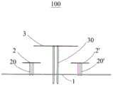
图1是本发明一实施例提供的多频共口径天线的立体示意图;FIG. 1 is a perspective view of a multi-frequency common-aperture antenna provided by an embodiment of the present invention;
图2是图1所示多频共口径天线的侧视示意图;Fig. 2 is a schematic side view of the multi-frequency common-aperture antenna shown in Fig. 1;
图3是图1所示多频共口径天线的俯视示意图;FIG. 3 is a schematic top view of the multi-frequency common-aperture antenna shown in FIG. 1;
图4是图1所示多频共口径天线的低频透波辐射单元的立体透视图;Fig. 4 is the three-dimensional perspective view of the low-frequency wave-transparent radiation unit of the multi-frequency co-aperture antenna shown in Fig. 1;
图5是图1所示多频共口径天线的低频透波辐射单元的俯视透视图;Fig. 5 is a top perspective view of the low-frequency wave-transparent radiation unit of the multi-frequency common-aperture antenna shown in Fig. 1;
图6为本发明低频透波辐射单元的驻波曲线示意图;Fig. 6 is a schematic diagram of a standing wave curve of a low-frequency transparent wave radiation unit of the present invention;
图7为本发明中频辐射天线的的驻波曲线示意图;Fig. 7 is a schematic diagram of a standing wave curve of an intermediate frequency radiation antenna of the present invention;
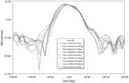
图8为本发明多频共口径天线在中频的水平面方向图;Fig. 8 is the horizontal plane pattern of the multi-frequency co-aperture antenna of the present invention at the intermediate frequency;
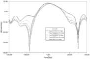
图9为本发明多频共口径天线在低频的水平面方向图。FIG. 9 is a horizontal plane pattern at low frequencies of the multi-frequency common-aperture antenna of the present invention.
具体实施方式Detailed ways
下面将结合附图对本发明实施例作进一步说明。Embodiments of the present invention will be further described below in conjunction with the accompanying drawings.
请参阅图1,本发明提供一种多频共口径天线100,包括反射板1、中频辐射天线2、低频透波辐射单元3。中频辐射天线2设置在反射板1与低频透波辐射单元3之间。中频辐射天线2、低频辐射天线3分别通过第一馈电线与第一支撑柱20、第二馈电线与第二支撑柱30与反射板1连接。Referring to FIG. 1 , the present invention provides a multi-frequency common-
请参阅图2和图3,低频透波辐射单元3与中频辐射天线2在垂直投影上具有重合区域。Please refer to FIG. 2 and FIG. 3 , the low-frequency wave-
本实施例中,反射板1、低频透波辐射单元3均为一个,中频辐射天线2为两个。两个中频辐射天线2相邻且具有间隔区域。低频透波辐射单元3的第二馈电线与第二支撑柱30设置在间隔区域内。低频透波辐射单元3设置在该预设距离正上方,并且低频辐射天线3的尺寸大于间隔区域的宽度。如此形成低频与中频共口径的天线结构。In this embodiment, there is one
其中,in,
请参阅图4和图5,低频透波辐射单元3包括加载透波支节32、PCB基板33,印制在PCB基板33上的四组低频辐射环形线路34和四组加载贴片35。PCB基板33的印制面为正方形,四组低频辐射环形线路34和四组加载贴片35分别对称布置在以PCB基板33的正方形印制面的中心构成的直角坐标系的四个象限内,即四组低频辐射环形线路34呈田字形排列。Please refer to FIG. 4 and FIG. 5 , the low-
优选地,加载透波支节32设置在低频辐射环形线路34中。如此加载透波支节32与低频辐射环形线路34形成并联连接结构,使加载透波支节32等效于电感电容电路,从而形成了不同频率的谐振点,具有能够使对应谐振点的频率实现透射的性能。可以理解地,通过改变加载透波支节32的整体长度、线宽或数量等,可以控制或调整加载透波支节32的透波的频率。Preferably, the loaded wave-
请参阅图3,更优选地,低频透波辐射单元3与中频辐射天线2在垂直投影上的重合区域对应设置有加载透波支节32。加载透波支节32能够弱化中频段与低频段间的耦合效应,从而使中频辐射天线2的中频电磁波的有效透射。Please refer to FIG. 3 , more preferably, the overlapping area of the low-frequency transparent
本实施例中,低频辐射环形线路34具有方形的环形线路主体341。方形的环形线路主体341的四条边均设置有加载透波支节32。如此,加载透波支节32与方形的环形线路主体341形成并联连接结构;从而形成更多的中频频率谐振点,增强中频辐射天线2的中频电磁波的透射。In this embodiment, the low frequency
更具体地,加载透波支节32包括单边透波支节321和双边透波支节322。在四个呈田字形排列的方形的环形线路主体341中,每一方形的环形线路主体341与另一方形的环形线路主体341相邻接的边上设置单边透波支节321,非相邻的边上设置双边透波支节322。根据图1和图2的多频共口径天线100的结构设计的需要,可以将单边透波支节321设置在靠近PCB基板33的印制面的中心的方形的环形线路主体341的边上;将双边透波支节322设置在方形的环形线路主体341中朝向外侧的边。如此,如图1和图2所示,在中频电磁波更集中辐射的低频透波辐射单元3与中频辐射天线2在垂直投影上的重合区域中通过双边透波支节322更有效地将中频电磁波透射出去;远离上述重合区域的地方设置单边透波支节321也可实现中频电磁波的有效透射;从而减少多频共口径天线100的生产成本,也实现了多频共口径天线100的轻量化;同时,在呈田字形排列的四组低频辐射环形线路34的“田字形”中心设置单边透波支节321,也使低频透波辐射单元3的结构排布更加密集,也能够缩小多频共口径天线100整体的体积。More specifically, the loaded wave
优选地,环形线路主体341的四个角的外边角为小倒圆角,环形线路主体341的四个角的内边角为大倒圆角,使方形的环形线路主体341具有若干U形分支。请参阅图5,低频透波辐射单元3具有四个方形的环形线路主体341;每一个环形线路主体341内具有四个U形分支。该四个U形分支还能够实现滤波,使四个U形分支等效为频率选择表面(FSS)。在本实施例中,该四个U形分支等效为中频辐射天线2的中频频率选择表面。该四个U形分支的阻带能够覆盖中频辐射天线2的中频工作频率,具体为1710MHz--2690MHz。进一步使中频辐射天线2的辐射性能不受低频透波辐射单元3的影响。Preferably, the outer corners of the four corners of the
本实施例中,PCB基板33为双面板;在多频共口径天线100的结构中,PCB基板33的朝向反射板1、中频辐射天线2方向的为PCB基板33的下面板;反之,远离反射板1、中频辐射天线2的为PCB基板33的上面板。低频辐射环形线路34、加载透波支节32和加载贴片35均设置在PCB基板33的下面板。具体地,每一组加载贴片35设置在对应的低频辐射环形线路34的环形内。优选地,每一组加载贴片35的位置相对其对应的低频辐射环形线路34的中心偏心设置。即每一组加载贴片35与对应的低频辐射环形线路34的四条边的距离不相同。如此,偏心设置的加载贴片35能调整阻抗,增加低频透波辐射单元3的带宽。同时,本实施例中,偏心设置的加载贴片35还增加了低频辐射与中频透波的谐振点,能够调整中频透波的频率,增加中频透波的带宽;即偏心设置的加载贴片35能够调整多频共口径天线100整体天线的工作频率和提高整体天线的工作带宽。In this embodiment, the
请参阅图4和图5,低频透波辐射单元3还包括馈电贴片组36。馈电贴片组36印制PCB基板33的上面板,且馈电贴片组36设置在PCB基板33的上面板的中心区域。Please refer to FIG. 4 and FIG. 5 , the low-frequency transparent
馈电贴片组36具有两个馈电贴片。每一馈电贴片具有两个端口,其中每一馈电贴片的一个端口连接第二馈电线,另一端口连接第二支撑柱30。例如,馈电贴片组36包括第一馈电贴片361和第二馈电贴片362;第一馈电贴片361具有第一馈电端口和第二馈电端口,第二馈电贴片362具有第三馈电端口和第四馈电端口。当第一馈电端口连接第二馈电线,则第二馈电端口连接第二支撑柱30,当第三馈电端口连接第二馈电线,则第四馈电端口连接第二支撑柱30;反之,第一馈电端口连接第二支撑柱30,则第二馈电端口连接第二馈电线,第三馈电端口连接第二支撑柱30,则第四馈电端口连接第二馈电线。The
优选地,第二支撑柱30具有四根空心金属管柱。第二馈电线共有两条。四根空心金属管柱或表面金属化管柱中,其中两根空心金属管柱用于收容第二馈电线。即仅有两根空心金属管柱内分别收容有第二馈电线,另外两根空心金属管柱没有馈电线,用于接地。该两条第二馈电线为同轴馈电电缆。两根用于接地的第二支撑柱30的上端、两条第二馈电线的上端分别连接到低频辐射环形线路34,且第二馈电线穿过低频辐射环形线路34与馈电贴片组36对应的馈电端口电连接。第二支撑柱30的下端、第二馈电线的下端分别固定到反射板1,并与反射板1电连接。可以理解地,第二支撑柱30也可以为表面金属化管柱。Preferably, the
在另一种实施方式中,第一馈电贴片361和第二馈电贴片362组成的馈电贴片组36、两根第二支撑柱30、两条第二馈电线、反射板1之间形成对角线对称的两组具有相同±45°的双极方向的馈电线路结构,能够实现多频共口径天线100的低频透波辐射单元3极化分集,可以工作在收发双工模式下,能极大减小天线数量和占用空间,从而实现天线小型化、轻量化的目的。In another embodiment, the
图6为本发明低频透波辐射单元3在低频工作频段820-960MHz范围内的驻波曲线,该驻波曲线显示低频透波辐射单元3的驻波基本不高于1.5;即低频透波辐射单元3在低频工作频段820-960MHz范围内具有良好的阻抗匹配。Fig. 6 is the standing wave curve of the low-frequency wave-transmitting
图7为本发明应用低频透波辐射单元3的多频共口径天线100的中频辐射天线2在中频工作频段1710-2170MHz范围内的驻波曲线,该驻波曲线显示通过低频透波辐射单元3的加载透波支节32弱化中频段与低频段间的耦合效应,实现中频辐射天线2的中频电磁波的有效透射;使中频辐射天线2的驻波在中频工作频段1710-2170MHz范围内均不高于1.5。其中图6和图7中的横坐标Freg为频率;“GHz”为角度的单位“千兆赫兹”,1GHz等于1000MHz;纵坐标VSWR 为驻波系数或驻波比。Fig. 7 is the standing wave curve of the intermediate
图8、图9分别为本发明多频共口径天线100在中频的水平面方向图、多频共口径天线100在低频的水平面方向图。在图8和图9中,横坐标Theta为角度;“deg”为角度的单位“度”;纵坐标Gain Total为总增益;“dB”为增益的单元“分贝”。图8显示了多频共口径天线100在中频的半功率波束宽度为55°-73°;图9显示了多频共口径天线100在低频的半功率波束宽度为60°-77°;即多频共口径天线100满足低频透波辐射单元3的辐射指标,同时也满足了中频辐射天线2的辐射指标。FIG. 8 and FIG. 9 are respectively the horizontal plane pattern of the multi-frequency common-
需要说明的是,在其它的实施例中,低频透波辐射单元3的加载透波支节32也能够弱化高频段与低频段间的耦合效应,实现高频辐射天线的高频电磁波的有效透射。It should be noted that, in other embodiments, the loaded wave-transmitting
以上所述实施例仅描述了本发明的几种实施方式,但并不能因此而理解为对本发明专利范围的限制。应当指出的是,对于本领域的普通技术人员来说,在不脱离本发明构思的前提下,还可以做出若干变形和改进,这些都属于本发明的保护范围。因此,本发明专利的保护范围应以所附权利要求为准。The above-mentioned embodiments only describe several implementations of the present invention, but should not be construed as limiting the patent scope of the present invention. It should be noted that, for those skilled in the art, several modifications and improvements can be made without departing from the concept of the present invention, and these all belong to the protection scope of the present invention. Therefore, the protection scope of the patent for the present invention should be based on the appended claims.
Claims (10)
Translated fromChinesePriority Applications (1)
| Application Number | Priority Date | Filing Date | Title |
|---|---|---|---|
| CN202310461455.2ACN116435767A (en) | 2023-04-26 | 2023-04-26 | Low-frequency wave-transmitting radiation unit and multi-frequency common-caliber antenna using same |
Applications Claiming Priority (1)
| Application Number | Priority Date | Filing Date | Title |
|---|---|---|---|
| CN202310461455.2ACN116435767A (en) | 2023-04-26 | 2023-04-26 | Low-frequency wave-transmitting radiation unit and multi-frequency common-caliber antenna using same |
Publications (1)
| Publication Number | Publication Date |
|---|---|
| CN116435767Atrue CN116435767A (en) | 2023-07-14 |
Family
ID=87085311
Family Applications (1)
| Application Number | Title | Priority Date | Filing Date |
|---|---|---|---|
| CN202310461455.2APendingCN116435767A (en) | 2023-04-26 | 2023-04-26 | Low-frequency wave-transmitting radiation unit and multi-frequency common-caliber antenna using same |
Country Status (1)
| Country | Link |
|---|---|
| CN (1) | CN116435767A (en) |
Cited By (1)
| Publication number | Priority date | Publication date | Assignee | Title |
|---|---|---|---|---|
| CN118336376A (en)* | 2024-06-12 | 2024-07-12 | 中天通信技术有限公司 | Wave-transmitting low-frequency antennas and antenna components |
Citations (2)
| Publication number | Priority date | Publication date | Assignee | Title |
|---|---|---|---|---|
| WO2021164117A1 (en)* | 2020-02-18 | 2021-08-26 | 摩比天线技术(深圳)有限公司 | Low-frequency antenna assembly with wave-transparent function, and dual-polarized antenna |
| CN114725698A (en)* | 2022-04-28 | 2022-07-08 | 华南理工大学 | Broadband wave-transmitting low-frequency antenna, multi-frequency common aperture antenna array and communication equipment |
- 2023
- 2023-04-26CNCN202310461455.2Apatent/CN116435767A/enactivePending
Patent Citations (2)
| Publication number | Priority date | Publication date | Assignee | Title |
|---|---|---|---|---|
| WO2021164117A1 (en)* | 2020-02-18 | 2021-08-26 | 摩比天线技术(深圳)有限公司 | Low-frequency antenna assembly with wave-transparent function, and dual-polarized antenna |
| CN114725698A (en)* | 2022-04-28 | 2022-07-08 | 华南理工大学 | Broadband wave-transmitting low-frequency antenna, multi-frequency common aperture antenna array and communication equipment |
Non-Patent Citations (2)
| Title |
|---|
| HANG YUAN , FU-CHANG CHEN,: "Dual-Band Base Station Antenna Array With Cross-Band Scattering and In-Band Coupling Suppression", IEEE TRANSACTIONS ON ANTENNAS AND PROPAGATION, 15 March 2023 (2023-03-15), pages 1 - 19* |
| WEI NIU , BAOHUA SUN,: "Dual-Band Aperture Shared Antenna Array With Decreased Radiation Pattern Distortion", IEEE TRANSACTIONS ON ANTENNAS AND PROPAGATION, 31 July 2022 (2022-07-31), pages 1 - 14* |
Cited By (1)
| Publication number | Priority date | Publication date | Assignee | Title |
|---|---|---|---|---|
| CN118336376A (en)* | 2024-06-12 | 2024-07-12 | 中天通信技术有限公司 | Wave-transmitting low-frequency antennas and antenna components |
Similar Documents
| Publication | Publication Date | Title |
|---|---|---|
| US11575197B2 (en) | Multi-band antenna having passive radiation-filtering elements therein | |
| US11831084B2 (en) | Dual-polarized antenna, antenna array, and communications device | |
| EP4030558B1 (en) | Common aperture antenna and communication device | |
| CN201655979U (en) | Combined type multi-input multi-output antenna module and system thereof | |
| CN109659674B (en) | Communication antenna and radiation unit thereof | |
| US20120062437A1 (en) | Antenna system with planar dipole antennas and electronic apparatus having the same | |
| CN113036400A (en) | Radiating element, antenna assembly and base station antenna | |
| KR101541374B1 (en) | Dual Polarization Dipole Antenna for Multi-Band and System including the same | |
| WO2020187207A1 (en) | Antenna unit and filtering antenna array | |
| US11831085B2 (en) | Compact antenna radiating element | |
| WO2022053156A1 (en) | Antenna device, array of antenna devices, and base station with antenna device | |
| WO2022133922A1 (en) | Multi-frequency antenna and communication device | |
| WO2022095981A1 (en) | Multi-band fusion antenna assembly | |
| EP3913746B1 (en) | Antenna and communications device | |
| JP2023543278A (en) | antenna device, array of antenna devices | |
| WO2024146248A1 (en) | Array antenna | |
| WO2024104087A1 (en) | Antenna radiation unit and antenna | |
| CN211045708U (en) | Radiating elements, antenna assemblies and base station antennas | |
| CN114552220B (en) | Single-port double-frequency double-circular polarization filter antenna based on microstrip transmission line feed and wireless communication equipment | |
| CN116435767A (en) | Low-frequency wave-transmitting radiation unit and multi-frequency common-caliber antenna using same | |
| CN118572365B (en) | Low-profile dual-polarization low-frequency antenna, three-frequency co-aperture antenna array and communication equipment | |
| WO2023274173A1 (en) | Antenna structure, base station antenna, and base station | |
| CN117791099A (en) | Base station antenna loaded with decoupling super surface | |
| WO2023239568A1 (en) | Base station antennas having at least one grid reflector and related devices | |
| KR102846236B1 (en) | Omni-directional antenna apparatus |
Legal Events
| Date | Code | Title | Description |
|---|---|---|---|
| PB01 | Publication | ||
| PB01 | Publication | ||
| SE01 | Entry into force of request for substantive examination | ||
| SE01 | Entry into force of request for substantive examination |