CN116423347A - A board receiving device and method for printed boards with grooves - Google Patents
A board receiving device and method for printed boards with groovesDownload PDFInfo
- Publication number
- CN116423347A CN116423347ACN202310535148.4ACN202310535148ACN116423347ACN 116423347 ACN116423347 ACN 116423347ACN 202310535148 ACN202310535148 ACN 202310535148ACN 116423347 ACN116423347 ACN 116423347A
- Authority
- CN
- China
- Prior art keywords
- printed board
- oil cylinder
- piston rod
- grooved
- grooved printed
- Prior art date
- Legal status (The legal status is an assumption and is not a legal conclusion. Google has not performed a legal analysis and makes no representation as to the accuracy of the status listed.)
- Granted
Links
Images


Classifications
- B—PERFORMING OPERATIONS; TRANSPORTING
- B24—GRINDING; POLISHING
- B24B—MACHINES, DEVICES, OR PROCESSES FOR GRINDING OR POLISHING; DRESSING OR CONDITIONING OF ABRADING SURFACES; FEEDING OF GRINDING, POLISHING, OR LAPPING AGENTS
- B24B21/00—Machines or devices using grinding or polishing belts; Accessories therefor
- B24B21/002—Machines or devices using grinding or polishing belts; Accessories therefor for grinding edges or bevels
- B—PERFORMING OPERATIONS; TRANSPORTING
- B24—GRINDING; POLISHING
- B24B—MACHINES, DEVICES, OR PROCESSES FOR GRINDING OR POLISHING; DRESSING OR CONDITIONING OF ABRADING SURFACES; FEEDING OF GRINDING, POLISHING, OR LAPPING AGENTS
- B24B1/00—Processes of grinding or polishing; Use of auxiliary equipment in connection with such processes
- B—PERFORMING OPERATIONS; TRANSPORTING
- B24—GRINDING; POLISHING
- B24B—MACHINES, DEVICES, OR PROCESSES FOR GRINDING OR POLISHING; DRESSING OR CONDITIONING OF ABRADING SURFACES; FEEDING OF GRINDING, POLISHING, OR LAPPING AGENTS
- B24B21/00—Machines or devices using grinding or polishing belts; Accessories therefor
- B24B21/18—Accessories
- B—PERFORMING OPERATIONS; TRANSPORTING
- B24—GRINDING; POLISHING
- B24B—MACHINES, DEVICES, OR PROCESSES FOR GRINDING OR POLISHING; DRESSING OR CONDITIONING OF ABRADING SURFACES; FEEDING OF GRINDING, POLISHING, OR LAPPING AGENTS
- B24B41/00—Component parts such as frames, beds, carriages, headstocks
- B24B41/005—Feeding or manipulating devices specially adapted to grinding machines
- B—PERFORMING OPERATIONS; TRANSPORTING
- B24—GRINDING; POLISHING
- B24B—MACHINES, DEVICES, OR PROCESSES FOR GRINDING OR POLISHING; DRESSING OR CONDITIONING OF ABRADING SURFACES; FEEDING OF GRINDING, POLISHING, OR LAPPING AGENTS
- B24B41/00—Component parts such as frames, beds, carriages, headstocks
- B24B41/06—Work supports, e.g. adjustable steadies
- B24B41/068—Table-like supports for panels, sheets or the like
- B—PERFORMING OPERATIONS; TRANSPORTING
- B24—GRINDING; POLISHING
- B24B—MACHINES, DEVICES, OR PROCESSES FOR GRINDING OR POLISHING; DRESSING OR CONDITIONING OF ABRADING SURFACES; FEEDING OF GRINDING, POLISHING, OR LAPPING AGENTS
- B24B47/00—Drives or gearings; Equipment therefor
- B—PERFORMING OPERATIONS; TRANSPORTING
- B24—GRINDING; POLISHING
- B24B—MACHINES, DEVICES, OR PROCESSES FOR GRINDING OR POLISHING; DRESSING OR CONDITIONING OF ABRADING SURFACES; FEEDING OF GRINDING, POLISHING, OR LAPPING AGENTS
- B24B47/00—Drives or gearings; Equipment therefor
- B24B47/02—Drives or gearings; Equipment therefor for performing a reciprocating movement of carriages or work- tables
- B24B47/06—Drives or gearings; Equipment therefor for performing a reciprocating movement of carriages or work- tables by liquid or gas pressure only
- B—PERFORMING OPERATIONS; TRANSPORTING
- B24—GRINDING; POLISHING
- B24B—MACHINES, DEVICES, OR PROCESSES FOR GRINDING OR POLISHING; DRESSING OR CONDITIONING OF ABRADING SURFACES; FEEDING OF GRINDING, POLISHING, OR LAPPING AGENTS
- B24B55/00—Safety devices for grinding or polishing machines; Accessories fitted to grinding or polishing machines for keeping tools or parts of the machine in good working condition
- B24B55/06—Dust extraction equipment on grinding or polishing machines
- B24B55/08—Dust extraction equipment on grinding or polishing machines specially designed for belt grinding machines
- Y—GENERAL TAGGING OF NEW TECHNOLOGICAL DEVELOPMENTS; GENERAL TAGGING OF CROSS-SECTIONAL TECHNOLOGIES SPANNING OVER SEVERAL SECTIONS OF THE IPC; TECHNICAL SUBJECTS COVERED BY FORMER USPC CROSS-REFERENCE ART COLLECTIONS [XRACs] AND DIGESTS
- Y02—TECHNOLOGIES OR APPLICATIONS FOR MITIGATION OR ADAPTATION AGAINST CLIMATE CHANGE
- Y02P—CLIMATE CHANGE MITIGATION TECHNOLOGIES IN THE PRODUCTION OR PROCESSING OF GOODS
- Y02P70/00—Climate change mitigation technologies in the production process for final industrial or consumer products
- Y02P70/10—Greenhouse gas [GHG] capture, material saving, heat recovery or other energy efficient measures, e.g. motor control, characterised by manufacturing processes, e.g. for rolling metal or metal working
Landscapes
- Engineering & Computer Science (AREA)
- Mechanical Engineering (AREA)
- Manufacturing Of Printed Wiring (AREA)
Abstract
Description
Translated fromChinese技术领域technical field
本发明涉及带槽印制板收放到料筐内的技术领域,特别是一种用于带槽印制板的收板装置及方法。The invention relates to the technical field of storing printed boards with grooves into a material basket, in particular to a board receiving device and method for printed boards with grooves.
背景技术Background technique
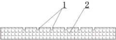
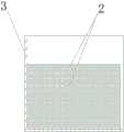
某带槽印制板的结构如图1~图2所示,它包括板体,板体的顶表面上沿其纵向上铣削成型出有多个条形槽1,条形槽1内用于安装电子元件器。当这种带槽印制板从前段开槽机输送出来后,工艺上要求将输送出来的带槽印制板2堆叠在料筐3内,以实现对带槽印制板2的收板,如图3~图5所示为将多个带槽印制板收放到料筐内的示意图。The structure of a grooved printed board is shown in Figures 1 to 2. It includes a board body, and a plurality of
某车间采用如图6~图7所示的收板装置来将输送出来的带槽印制板2收放到料筐3内,该收板装置包括从左往右顺次设置于垫板4上的料筐3、机械手臂5和滚筒输送机6,料筐3的右端部开设有与其相连通的开口,机械手臂5的执行端上固设有真空吸盘7,真空吸盘7的接头与真空泵经软管连接,滚筒输送机6的前机架和后机架之间固设有挡板8,前机架和后机架的顶表面上沿其长度方向固设有护板9,两个护板9之间的间距与带槽印制板2的纵向宽度相等。A certain workshop adopts the receiving device as shown in Fig. 6 to Fig. 7 to store the conveyed printed
该收板装置的工作方法是:The working method of this board receiving device is:
S1、当从开槽机输送出来的带槽印制板2落入到滚筒输送机6的滚筒10上时,控制滚筒输送机6启动,滚筒输送机6带动各个滚筒10转动,滚筒10将带槽印制板2朝左输送;S1. When the grooved printed
S2、当带槽印制板2被挡板8挡住后,如图8所示,控制机械手臂5动作,机械手臂5带动真空吸盘7朝向带槽印制板2方向运动,当真空吸盘7的底表面与带槽印制板2的顶表面相接触后,控制真空泵启动,真空泵对真空吸盘7的内腔抽真空,在负压下,带槽印制板2吸附在真空吸盘7上;然后控制机械手臂5将真空吸盘7向上提起,真空吸盘7将带槽印制板2提升起来,如图9所示,最后控制机械手臂5将提升起来的带槽印制板2送入到料筐3内,从而实现了对第一个带槽印制板2的输送;S2. When the grooved printed
S3、如此重复步骤S1~S2的操作,即可连续地将从开槽机输送出来的多个带槽印制板2收放到料筐3内,如图10所示。S3. By repeating steps S1-S2, the multiple printed
然而,这种收板装置虽然能够将多个带槽印制板2收放到料筐3内,但是在实际的操作过程中,仍然存在以下技术缺陷:However, although this board receiving device can store a plurality of grooved printed
I、在步骤S3中,当多个带槽印制板2收放在料筐3内后,由于各个条形槽1的外边缘上均带有向上凸起的毛刺11(毛刺是开槽机在开条形槽时所产生),如图5所示,从而导致下层带槽印制板2上的毛刺11刮伤上层带槽印制板2的底表面,无法满足客户的需求。I, in step S3, after a plurality of grooved printed
II、在步骤S2中,真空吸盘7仅凭负压力将带槽印制板2吸附住,而带槽印制板2的整体重量大,且带槽印制板2的底部没有任何支撑,当真空吸盘7带动带槽印制板2朝向料筐3运动时,带槽印制板2很容易从真空吸盘7上脱落下来,脱落下来的带槽印制板2撞击到地面而受损,同时增加了对后续带槽印制板2的收板时间,从而极大的降低了带槽印制板的收板效率。因此,亟需一种避免收板后带槽印制板的底表面刮伤、极大提高带槽印制板收板效率的收板装置及方法。II. In step S2, the
发明内容Contents of the invention
本发明的目的在于克服现有技术的缺点,提供一种避免收板后带槽印制板的底表面刮伤、极大提高带槽印制板收板效率、自动化程度高的用于带槽印制板的收板装置及方法。The purpose of the present invention is to overcome the shortcomings of the prior art, to provide a grooved printed board for avoiding scratches on the bottom surface of the grooved printed board after receiving the board, greatly improving the efficiency of receiving the grooved printed board, and having a high degree of automation. A board receiving device and method for printed boards.
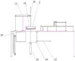
本发明的目的通过以下技术方案来实现:一种用于带槽印制板的收板装置,它包括设置于工作台台面上的滚筒输送机,所述工作台的台面上固设有多个位于滚筒输送机正下方的顶升油缸,工作台的台面上设置有用于打磨带槽印制板上毛刺的打磨机构,打磨机构设置于滚筒输送机的正上方;The purpose of the present invention is achieved through the following technical solutions: a board receiving device for printed boards with grooves, which includes a roller conveyor arranged on the table top of the work table, and a plurality of The jacking cylinder is located directly below the roller conveyor, and the workbench is provided with a grinding mechanism for grinding burrs on the printed board with grooves, and the grinding mechanism is arranged directly above the roller conveyor;
所述工作台的台面上还设置有用于周转带槽印制板的周转机构,周转机构设置于滚筒输送机的左侧,周转机构包括固设于工作台台面上的左机台、固设于左机台顶表面上的水平油缸、固设于水平油缸活塞杆作用端上的连接板,连接板的顶部固设有垂向油缸,垂向油缸的活塞杆贯穿连接板设置,且延伸端上设置有用于抓取带槽印制板的抓取机构,所述抓取机构包括焊接于垂向油缸活塞杆作用端上的安装板,安装板的左右端部均设置有伸缩油缸,伸缩油缸的缸筒铰接于安装板上,安装板的左右端均铰接有位于伸缩油缸外侧的L板,伸缩油缸的活塞杆铰接于L板的长板上;The table of the workbench is also provided with a turnover mechanism for turning over the grooved printed board. The turnover mechanism is arranged on the left side of the roller conveyor. The horizontal oil cylinder on the top surface of the left machine table, the connection plate fixed on the piston rod of the horizontal oil cylinder, the vertical oil cylinder is fixed on the top of the connection plate, the piston rod of the vertical oil cylinder is set through the connection plate, and the extension end is A grabbing mechanism for grabbing printed boards with grooves is provided. The grabbing mechanism includes a mounting plate welded to the active end of the piston rod of the vertical oil cylinder. The left and right ends of the mounting plate are equipped with telescopic oil cylinders. The cylinder barrel is hinged on the mounting plate, and the left and right ends of the mounting plate are hinged with the L plate located outside the telescopic oil cylinder, and the piston rod of the telescopic oil cylinder is hinged on the long plate of the L plate;
所述工作台上开设有位于周转机构与滚筒输送机之间的通槽,通槽的正下方设置有固设于工作台底表面上的支架,支架的底壁上固设有升降油缸,升降油缸的活塞杆向上贯穿通槽设置,且延伸端上固设有升降板,支架的右侧壁上固设有推送油缸,推送油缸的活塞杆贯穿支架设置,且延伸端上固设有推板;The workbench is provided with a through groove between the turnover mechanism and the roller conveyor, and a bracket fixed on the bottom surface of the workbench is arranged directly below the through groove, and a lifting oil cylinder is fixed on the bottom wall of the bracket to lift The piston rod of the oil cylinder is set upward through the through groove, and the extension end is fixed with a lifting plate, and the right side wall of the bracket is fixed with a push cylinder, and the piston rod of the push cylinder is set through the bracket, and a push plate is fixed on the extension end ;
所述工作台的底表面上且位于通槽的左侧设置有垂向设置的丝杆螺母副,丝杆螺母副的螺母上焊接有支撑板,支撑板的台面上放置有料筐,料筐的开口与推板左右相对立设置。On the bottom surface of the workbench and on the left side of the through groove, a vertically arranged screw nut pair is arranged. A support plate is welded on the nut of the screw nut pair. A material basket is placed on the table surface of the support plate. The opening is arranged opposite to the left and right sides of the push plate.
所述滚筒输送机的前机架和后机架之间固设有挡板,前机架和后机架的顶表面上沿其长度方向固设有护板,两个护板之间的间距与带槽印制板的纵向宽度相等。A baffle plate is fixed between the front frame and the rear frame of the roller conveyor, and guard plates are fixed on the top surfaces of the front frame and the rear frame along their length directions, and the distance between the two guard plates Equal to the longitudinal width of the grooved printed board.
所述打磨机构包括固设于工作台台面上的右机台、固设于右机台台面上的进给油缸,进给油缸活塞杆的作用端上固设有平台,平台的底表面上焊接有框架和出风盘,框架设置于出风盘的左侧,框架内旋转安装有主动砂带辊和从动砂带辊,主动砂带辊与从动砂带辊之间安装有砂带,框架的后侧壁上固设有驱动电机,驱动电机与主动砂带辊连接;所述出风盘的底部设置有斜面,斜面上开设有多个与出风盘内腔相连通的出风孔;所述平台的顶部还固设有鼓风机,鼓风机的出风管与出风盘的内腔相连通。The grinding mechanism includes a right machine platform fixed on the table top of the workbench, a feed oil cylinder fixed on the table top of the right machine table, a platform is fixed on the action end of the piston rod of the feed oil cylinder, and a platform is welded on the bottom surface of the platform. There is a frame and an air outlet disk, the frame is set on the left side of the air outlet disk, a driving abrasive belt roller and a driven abrasive belt roller are installed in rotation in the frame, and an abrasive belt is installed between the driving abrasive belt roller and the driven abrasive belt roller. A drive motor is fixed on the rear side wall of the frame, and the drive motor is connected with the active abrasive belt roller; the bottom of the air outlet pan is provided with a slope, and a plurality of air outlet holes communicating with the inner cavity of the air outlet pan are opened on the slope The top of the platform is also fixed with a blower, and the air outlet pipe of the air blower communicates with the inner cavity of the air outlet disk.
两个伸缩油缸左右对称设置,两个L板左右对称设置。The two telescopic oil cylinders are symmetrically arranged left and right, and the two L plates are arranged symmetrically left and right.
所述工作台的底表面上固设有多根支撑于地面上的支撑腿。A plurality of support legs supported on the ground are fixed on the bottom surface of the workbench.
所述丝杆螺母副包括伺服电机、螺母和固设于工作台底表面上的安装座,安装座内旋转安装有垂向设置的丝杆,螺母螺纹连接于丝杆上,螺母内贯穿有光杆,光杆的上下端均固设于安装座上,伺服电机固设于安装座的底部,伺服电机的输出轴与丝杆的下端部连接。The screw nut pair includes a servo motor, a nut, and a mounting seat fixed on the bottom surface of the workbench. A vertical screw rod is installed in the mounting seat. The nut is threaded on the screw rod, and a polished rod runs through the nut. , the upper and lower ends of the polished rod are fixed on the mounting base, the servo motor is fixed on the bottom of the mounting base, and the output shaft of the servo motor is connected with the lower end of the screw rod.
该收板装置还包括控制器,所述控制器与垂向油缸的电磁阀、水平油缸的电磁阀、进给油缸的电磁阀、升降油缸的电磁阀、顶升油缸的电磁阀、推送油缸的电磁阀、驱动电机、伺服电机和滚筒输送机连接。The board receiving device also includes a controller, and the controller is connected with the solenoid valve of the vertical oil cylinder, the solenoid valve of the horizontal oil cylinder, the solenoid valve of the feed oil cylinder, the solenoid valve of the lifting oil cylinder, the solenoid valve of the jacking oil cylinder, and the solenoid valve of the pushing oil cylinder. Solenoid valve, driving motor, servo motor and roller conveyor are connected.
一种用于带槽印制板的收板方法,它包括以下步骤:A board receiving method for printed boards with slots, comprising the following steps:
S1、当从开槽机输送出来的带槽印制板落入到滚筒输送机的滚筒上时,控制滚筒输送机启动,滚筒输送机带动各个滚筒转动,滚筒将带槽印制板朝左输送,当带槽印制板被挡板挡住后,控制滚筒输送机关闭;S1. When the grooved printed board conveyed from the slotting machine falls onto the roller of the roller conveyor, the roller conveyor is controlled to start, and the roller conveyor drives each roller to rotate, and the roller conveys the grooved printed board to the left , when the grooved printed board is blocked by the baffle, the roller conveyor is controlled to close;
S2、带槽印制板上毛刺的打磨,其具体操作步骤为:S2. Grinding the burr on the grooved printed board, the specific operation steps are:
S21、控制驱动电机启动,驱动电机带动主动砂带辊启动,主动砂带辊带动砂带在垂直面上旋转,同时启动鼓风机,鼓风机向出风盘的内腔中鼓送气流,气流从出风盘的出风孔处倾斜喷出;S21. Control the drive motor to start, the drive motor drives the active abrasive belt roller to start, the active abrasive belt roller drives the abrasive belt to rotate on the vertical plane, and at the same time starts the blower, the blower blows airflow into the inner cavity of the air outlet plate, and the airflow flows from the air outlet The air outlet of the disk is sprayed obliquely;
S22、控制进给油缸的活塞杆向左伸出,活塞杆带动平台向左做直线运动,平台带动框架、砂带和出风盘同步向左做直线运动,砂带贴在带槽印制板的顶表面上移动,砂带在向左运动过程中,将带槽印制板上各个条形槽外边缘上的毛刺全部打磨掉,同时从出风孔喷出的气流将打磨时所产生的废屑吹掉,当进给油缸的活塞杆完全伸出后,即可打磨掉带槽印制板上的所有毛刺;S22. The piston rod that controls the feed cylinder extends to the left, the piston rod drives the platform to make a linear motion to the left, the platform drives the frame, the abrasive belt and the air outlet plate to make a linear motion to the left synchronously, and the abrasive belt is attached to the grooved printed board During the movement of the abrasive belt to the left, all the burrs on the outer edge of each strip groove on the grooved printed board will be polished off, and at the same time, the airflow ejected from the air outlet will remove the burrs generated during grinding. The scrap is blown off, and when the piston rod of the feed cylinder is fully extended, all the burrs on the grooved printed board can be polished off;
S3、当打磨后,控制顶升油缸的活塞杆向上伸出,活塞杆穿过滚筒输送机的滚筒后将带槽印制板向上顶起,当顶升油缸的活塞杆完全伸出后,即可将打磨后的带槽印制板向上顶起;S3. After grinding, control the piston rod of the jacking cylinder to extend upwards. After the piston rod passes through the roller of the roller conveyor, the printed board with grooves will be lifted upwards. When the piston rod of the jacking cylinder is fully extended, that is The polished printed circuit board with grooves can be lifted up;
S4、带槽印制板的周转,其具体操作步骤为:S4. The turnover of printed boards with grooves, the specific operation steps are:
S41、控制水平油缸的活塞杆向右伸出,活塞杆带动连接板、垂向油缸和抓取机构同步向右做直线运动,当水平油缸的活塞杆完全伸出后,抓取机构刚好运动到带槽印制板的正上方;S41. Control the piston rod of the horizontal oil cylinder to stretch out to the right, and the piston rod drives the connecting plate, the vertical oil cylinder and the grabbing mechanism to move in a straight line to the right synchronously. When the piston rod of the horizontal oil cylinder is fully extended, the grabbing mechanism just moves to Directly above the slotted printed board;
S42、控制抓取机构的两个伸缩油缸的活塞杆缩回,活塞杆带动L板朝带槽印制板方向运动,当两个伸缩油缸的活塞杆完全缩回,两个L板的短板分别将带槽印制板的左右端部抬住,同时两个L板的长板将带槽印制板夹持固定住,从而实现了带槽印制板的抓取;S42. The piston rods of the two telescopic oil cylinders that control the grasping mechanism are retracted, and the piston rods drive the L plate to move toward the grooved printed board. When the piston rods of the two telescopic oil cylinders are fully retracted, the short plate of the two L plates Lift the left and right ends of the printed board with groove respectively, and at the same time, the long plates of the two L boards clamp and fix the printed board with groove, so as to realize the grasping of the printed board with groove;
S43、控制水平油缸的活塞杆向左缩回,活塞杆带动连接板、垂向油缸、抓取机构和带槽印制板同步向左运动,当水平油缸的活塞杆完全缩回,带槽印制板刚好运动到升降板的正上方;S43. Control the piston rod of the horizontal oil cylinder to retract to the left, and the piston rod drives the connecting plate, the vertical oil cylinder, the grabbing mechanism and the printed board with groove to move synchronously to the left. When the piston rod of the horizontal oil cylinder is fully retracted, the grooved printed The plate just moves to the top of the lifting plate;
S44、控制垂向油缸的活塞杆向下伸出,活塞杆带动抓取机构和带槽印制板同步向下运动,当垂向油缸的活塞杆完全伸出后,带槽印制板的底表面刚好与升降板的顶表面相接触;S44. Control the piston rod of the vertical oil cylinder to stretch out downwards, and the piston rod drives the grasping mechanism and the grooved printed board to move downward synchronously. When the piston rod of the vertical oil cylinder is fully extended, the bottom of the grooved printed board The surface is just in contact with the top surface of the lifting plate;
S45、控制抓取机构的两个伸缩油缸的活塞杆伸出,活塞杆带动L板朝远离带槽印制板方向运动,随后控制垂向油缸的活塞杆向上缩回,活塞杆带动抓取机构向上运动,从而最终实现了带槽印制板的周转;S45. The piston rods of the two telescopic oil cylinders that control the grasping mechanism are stretched out, and the piston rods drive the L plate to move away from the printed board with grooves, and then the piston rods that control the vertical oil cylinder retract upwards, and the piston rods drive the grasping mechanism upward movement, thus finally realizing the turnover of the grooved printed board;
S5、第一个带槽印制板的收板,其具体操作步骤为:S5. The first receiving board with grooved printed board, the specific operation steps are:
S51、控制升降油缸的活塞杆向下缩回,活塞杆带动升降板向下运动,升降板带动带槽印制板同步向下运动,当升降油缸的活塞杆完全缩回后,带槽印制板刚好与推板相对立;S51. Control the piston rod of the lifting cylinder to retract downward. The piston rod drives the lifting plate to move downward. The lifting plate drives the grooved printed board to move downward synchronously. When the piston rod of the lifting cylinder is fully retracted, the printed The plate is just opposite to the push plate;
S52、控制推送油缸的活塞杆向左伸出,活塞杆带动推板向左运动,推板将带槽印制板推送到料筐内,从而实现了第一个带槽印制板的收板;S52. Control the piston rod of the push cylinder to stretch out to the left, and the piston rod drives the push plate to move to the left, and the push plate pushes the printed board with grooves into the material basket, thus realizing the first collection of printed boards with grooves ;
S6、当完成第一个带槽印制板完成收板后,控制推送油缸的活塞杆向右缩回,活塞杆带动推板复位,随后控制升降油缸的活塞杆向上伸出,活塞杆带动升降板复位,复位后,控制伺服电机启动,伺服电机带动丝杆转动,螺母沿着丝杆向下运动一段距离,螺母带动支撑板和料筐同步向下运动距离,从而实料筐进入到下一个收板工位;S6. When the first printed board with groove is completed, the piston rod of the push cylinder is controlled to retract to the right, and the piston rod drives the push plate to reset, and then the piston rod of the lift cylinder is controlled to extend upward, and the piston rod drives the lift Plate reset, after reset, control the servo motor to start, the servo motor drives the screw to rotate, the nut moves down a certain distance along the screw, and the nut drives the support plate and the material basket to move downward synchronously, so that the material basket enters the next Receiving station;
S7、如此重复步骤S1~S6的操作,即可将连续地将从开槽机输送出来的多个带槽印制板收放到料筐内。S7. Repeating the operations of steps S1-S6 in this way, the multiple printed boards with grooves conveyed from the slotting machine can be continuously stored into the material basket.
本发明具有以下优点:避免收板后带槽印制板的底表面刮伤、极大提高带槽印制板收板效率、自动化程度高。The invention has the following advantages: avoiding scratches on the bottom surface of the grooved printed board after receiving the board, greatly improving the receiving efficiency of the grooved printed board, and high degree of automation.
附图说明Description of drawings
图1为带槽印制板的结构示意图;Fig. 1 is a structural schematic diagram of a slotted printed board;
图2为图1的左视图;Fig. 2 is the left view of Fig. 1;
图3为多个带槽印制板收放到料筐内的示意图;Fig. 3 is a schematic diagram of a plurality of printed boards with grooves being put into the material basket;
图4为图3的右视图;Fig. 4 is the right view of Fig. 3;
图5为图4的I部局部放大图;Fig. 5 is a partial enlarged view of part I of Fig. 4;
图6为某车间所使用的收板装置的结构示意图;Fig. 6 is a structural schematic diagram of a board receiving device used in a certain workshop;
图7为图6的俯视图;Figure 7 is a top view of Figure 6;
图8为带槽印制板被挡板挡住的示意图;Fig. 8 is a schematic diagram of a grooved printed board being blocked by a baffle;
图9为真空吸盘将带槽印制板提升起来的示意图;Fig. 9 is a schematic diagram of lifting the grooved printed board by a vacuum suction cup;
图10为将多个带槽印制板收放到料筐内的示意图;Fig. 10 is a schematic diagram of storing a plurality of printed boards with grooves into the material basket;
图11为本发明的结构示意图;Fig. 11 is a structural schematic diagram of the present invention;
图12为打磨机构的结构示意图;Fig. 12 is the structural representation of grinding mechanism;
图13为图12的A向示意图;Fig. 13 is a schematic diagram of direction A of Fig. 12;
图14为图12的II部局部放大图;Fig. 14 is a partially enlarged view of part II of Fig. 12;
图15 为周转机构的结构示意图;Fig. 15 is a structural schematic diagram of the revolving mechanism;
图16为丝杆螺母副的结构示意图;Fig. 16 is the structural representation of screw nut pair;
图17为滚筒输送机的结构示意图;Fig. 17 is the structural representation of roller conveyor;
图18为图17的俯视图;Figure 18 is a top view of Figure 17;
图19为带槽印制板落在滚筒上的示意图;Figure 19 is a schematic diagram of a grooved printed board falling on a drum;
图20为本发明的挡板将带槽印制板挡住的示意图;Fig. 20 is a schematic diagram of the baffle plate of the present invention blocking the grooved printed board;
图21为砂带贴在带槽印制板的顶表面上移动的示意图;Fig. 21 is a schematic diagram showing that the abrasive belt moves on the top surface of the grooved printed board;
图22为砂带打磨掉带槽印制板上所有毛刺的示意图;Fig. 22 is a schematic diagram of grinding off all burrs on the grooved printed board with an abrasive belt;
图23为顶升油缸将带槽印制板顶升起来的示意图;Fig. 23 is a schematic diagram of jacking up the printed board with grooves by the jacking cylinder;
图24为抓取机构刚好运动到带槽印制板正上方的示意图;Fig. 24 is a schematic diagram of the grabbing mechanism just moving to the top of the grooved printed board;
图25为抓取机构抓取住带槽印制板的示意图;Fig. 25 is a schematic diagram of the grasping mechanism grasping the grooved printed board;
图26为图25的III部局部放大图;Fig. 26 is a partially enlarged view of part III of Fig. 25;
图27为带槽印制板刚好运动到升降板正上方的示意图;Figure 27 is a schematic diagram of the grooved printed board just moving to the top of the lifting plate;
图28为带槽印制板的底表面刚好与升降板的顶表面相接触的示意图;Fig. 28 is a schematic diagram showing that the bottom surface of the grooved printed board is just in contact with the top surface of the lifting plate;
图29为将带槽印制板周转到升降板上的示意图;Fig. 29 is a schematic diagram of transferring the grooved printed board to the lifting plate;
图30为升降板带动带槽印制板向下运动的示意图;Figure 30 is a schematic diagram of the downward movement of the printed board with grooves driven by the lifting plate;
图31为推板将带槽印制板推送到料筐内的示意图;Fig. 31 is a schematic diagram of pushing the grooved printed board into the material basket by the push plate;
图32为将多个带槽印制板收放到料筐内的示意图;Fig. 32 is a schematic diagram of storing a plurality of printed boards with grooves into the material basket;
图中,1-条形槽,2-带槽印制板,3-料筐,4-垫板,5-机械手臂,6-滚筒输送机,7-真空吸盘,8-挡板,9-护板,10-滚筒,11-毛刺;In the figure, 1-strip groove, 2-printed board with groove, 3-basket, 4-backing plate, 5-mechanical arm, 6-roller conveyor, 7-vacuum suction cup, 8-baffle plate, 9- Guard plate, 10-roller, 11-burr;
12-工作台,13-顶升油缸,14-打磨机构,15-周转机构,16-左机台,17-水平油缸,18-垂向油缸,19-抓取机构,20-安装板,21-伸缩油缸,22-L板,23-通槽,24-支架,25-升降油缸,26-升降板,27-推送油缸,28-推板,29-丝杆螺母副,30-支撑板,31-右机台,32-进给油缸,33-平台,34-框架,35-出风盘,36-主动砂带辊,37-从动砂带辊,38-砂带,39-驱动电机,40-出风孔,41-鼓风机,42-伺服电机,43-螺母,44-安装座,45-丝杆。12-workbench, 13-jacking cylinder, 14-grinding mechanism, 15-turnover mechanism, 16-left machine, 17-horizontal cylinder, 18-vertical cylinder, 19-grabbing mechanism, 20-installation plate, 21 - telescopic cylinder, 22-L plate, 23-through slot, 24-bracket, 25-lift cylinder, 26-lift plate, 27-push cylinder, 28-push plate, 29-screw nut pair, 30-support plate, 31-right machine, 32-feed cylinder, 33-platform, 34-frame, 35-outlet disk, 36-active abrasive belt roller, 37-driven abrasive belt roller, 38-abrasive belt, 39-drive motor , 40-air outlet, 41-blower, 42-servo motor, 43-nut, 44-mounting seat, 45-screw.
具体实施方式Detailed ways
下面结合附图对本发明做进一步的描述,本发明的保护范围不局限于以下所述:The present invention will be further described below in conjunction with accompanying drawing, protection scope of the present invention is not limited to the following:
如图11~图18所示,一种用于带槽印制板的收板装置,它包括设置于工作台12台面上的滚筒输送机6,工作台12的底表面上固设有多根支撑于地面上的支撑腿,所述工作台12的台面上固设有多个位于滚筒输送机6正下方的顶升油缸13,工作台12的台面上设置有用于打磨带槽印制板2上毛刺11的打磨机构14,打磨机构14设置于滚筒输送机6的正上方;所述工作台12的台面上还设置有用于周转带槽印制板2的周转机构15,周转机构15设置于滚筒输送机6的左侧,周转机构15包括固设于工作台12台面上的左机台16、固设于左机台16顶表面上的水平油缸17、固设于水平油缸17活塞杆作用端上的连接板,连接板的顶部固设有垂向油缸18,垂向油缸18的活塞杆贯穿连接板设置,且延伸端上设置有用于抓取带槽印制板2的抓取机构19,所述抓取机构19包括焊接于垂向油缸18活塞杆作用端上的安装板20,安装板20的左右端部均设置有伸缩油缸21,两个伸缩油缸21左右对称设置,伸缩油缸21的缸筒铰接于安装板20上,安装板20的左右端均铰接有位于伸缩油缸21外侧的L板22,两个L板22左右对称设置,伸缩油缸21的活塞杆铰接于L板22的长板上。As shown in Figures 11 to 18, a board collection device for printed boards with grooves includes a
所述工作台12上开设有位于周转机构15与滚筒输送机6之间的通槽23,通槽23的正下方设置有固设于工作台12底表面上的支架24,支架24的底壁上固设有升降油缸25,升降油缸25的活塞杆向上贯穿通槽23设置,且延伸端上固设有升降板26,支架24的右侧壁上固设有推送油缸27,推送油缸27的活塞杆贯穿支架24设置,且延伸端上固设有推板28;所述工作台12的底表面上且位于通槽23的左侧设置有垂向设置的丝杆螺母副29,丝杆螺母副29的螺母43上焊接有支撑板30,支撑板30的台面上放置有料筐3,料筐3的开口与推板28左右相对立设置。所述丝杆螺母副29包括伺服电机42、螺母43和固设于工作台12底表面上的安装座44,安装座44内旋转安装有垂向设置的丝杆45,螺母43螺纹连接于丝杆45上,螺母43内贯穿有光杆,光杆的上下端均固设于安装座44上,伺服电机42固设于安装座44的底部,伺服电机42的输出轴与丝杆45的下端部连接。The
所述滚筒输送机6的前机架和后机架之间固设有挡板8,前机架和后机架的顶表面上沿其长度方向固设有护板9,两个护板9之间的间距与带槽印制板2的纵向宽度相等。所述打磨机构14包括固设于工作台12台面上的右机台31、固设于右机台31台面上的进给油缸32,进给油缸32活塞杆的作用端上固设有平台33,平台33的底表面上焊接有框架34和出风盘35,框架34设置于出风盘35的左侧,框架34内旋转安装有主动砂带辊36和从动砂带辊37,主动砂带辊36与从动砂带辊37之间安装有砂带38,框架34的后侧壁上固设有驱动电机39,驱动电机39与主动砂带辊36连接;所述出风盘35的底部设置有斜面,斜面上开设有多个与出风盘35内腔相连通的出风孔40;所述平台33的顶部还固设有鼓风机41,鼓风机41的出风管与出风盘35的内腔相连通。A
该收板装置还包括控制器,所述控制器与垂向油缸18的电磁阀、水平油缸17的电磁阀、进给油缸32的电磁阀、升降油缸25的电磁阀、顶升油缸13的电磁阀、推送油缸27的电磁阀、驱动电机39、伺服电机42和滚筒输送机6连接,控制器可控制垂向油缸18、水平油缸17、进给油缸32、升降油缸25、顶升油缸13和推送油缸27活塞杆的伸出或缩回,同时还能控制驱动电机39、伺服电机42和滚筒输送机6的启动或关闭,具有自动化程度高的特点。The board receiving device also includes a controller, which is connected with the electromagnetic valve of the
一种用于带槽印制板的收板方法,它包括以下步骤:A board receiving method for printed boards with slots, comprising the following steps:
S1、当从开槽机输送出来的如图1~图2所示的带槽印制板2落入到滚筒输送机6的滚筒10上时,如图19所示,控制滚筒输送机6启动,滚筒输送机6带动各个滚筒10转动,滚筒10将带槽印制板2朝左输送,当带槽印制板2被挡板8挡住后,如图20所示,控制滚筒输送机6关闭;S1. When the grooved printed
S2、带槽印制板2上毛刺11的打磨,其具体操作步骤为:S2. Grinding the
S21、控制驱动电机39启动,驱动电机39带动主动砂带辊36启动,主动砂带辊36带动砂带38在垂直面上旋转,同时启动鼓风机41,鼓风机41向出风盘35的内腔中鼓送气流,气流从出风盘35的出风孔40处倾斜喷出;S21, control the
S22、控制进给油缸32的活塞杆向左伸出,活塞杆带动平台33向左做直线运动,平台33带动框架34、砂带38和出风盘35同步向左做直线运动,砂带38贴在带槽印制板2的顶表面上移动,如图21所示,砂带38在向左运动过程中,将带槽印制板2上各个条形槽1外边缘上的毛刺11全部打磨掉,同时从出风孔40喷出的气流将打磨时所产生的废屑吹掉,当进给油缸32的活塞杆完全伸出后,即可打磨掉带槽印制板2上的所有毛刺11,如图22所示;S22, control the piston rod of the
S3、当打磨后,控制顶升油缸13的活塞杆向上伸出,活塞杆穿过滚筒输送机6的滚筒10后将带槽印制板2向上顶起,当顶升油缸13的活塞杆完全伸出后,即可将打磨后的带槽印制板2向上顶起,如图23所示;S3. After grinding, control the piston rod of the jacking
S4、带槽印制板的周转,其具体操作步骤为:S4. The turnover of printed boards with grooves, the specific operation steps are:
S41、控制水平油缸17的活塞杆向右伸出,活塞杆带动连接板、垂向油缸18和抓取机构19同步向右做直线运动,当水平油缸17的活塞杆完全伸出后,抓取机构19刚好运动到带槽印制板2的正上方,如图24所示;S41. Control the piston rod of the
S42、控制抓取机构19的两个伸缩油缸21的活塞杆缩回,活塞杆带动L板22朝带槽印制板2方向运动,当两个伸缩油缸21的活塞杆完全缩回,两个L板22的短板分别将带槽印制板2的左右端部抬住,同时两个L板22的长板将带槽印制板2夹持固定住,从而实现了带槽印制板2的抓取,如图25~图26所示;S42, control the retraction of the piston rods of the two
S43、控制水平油缸17的活塞杆向左缩回,活塞杆带动连接板、垂向油缸18、抓取机构19和带槽印制板2同步向左运动,当水平油缸17的活塞杆完全缩回,带槽印制板2刚好运动到升降板26的正上方,如图27所示;S43, control the piston rod of the
S44、控制垂向油缸18的活塞杆向下伸出,活塞杆带动抓取机构19和带槽印制板2同步向下运动,当垂向油缸18的活塞杆完全伸出后,带槽印制板2的底表面刚好与升降板26的顶表面相接触,如图28所示;S44. Control the piston rod of the
S45、控制抓取机构19的两个伸缩油缸21的活塞杆伸出,活塞杆带动L板22朝远离带槽印制板2方向运动,随后控制垂向油缸18的活塞杆向上缩回,活塞杆带动抓取机构19向上运动,从而最终实现了带槽印制板2的周转,如图29所示;S45, control the piston rods of the two
其中,在该步骤S4中,先控制抓取机构19的两个伸缩油缸21的活塞杆缩回,而后再控制水平油缸17活塞杆的缩回,以实现带槽印制板2的周转;其中,当两个伸缩油缸21的活塞杆缩回时,两个L板22的短板分别将带槽印制板2的左右端部抬住,同时两个L板22的长板将带槽印制板2夹持住,从而实现对带槽印制板2的牢固固定,确保了在周转带槽印制板2的过程中,带槽印制板2不会从抓取机构19上脱落下来,因此该收板装置相比于如图6~图10所示的收板装置,起到了很好保护带槽印制板的作用,同时缩短了后续带槽印制板的收板时间,从而极大的提高了带槽印制板的收板效率。Wherein, in this step S4, first control the retraction of the piston rods of the two
S5、第一个带槽印制板2的收板,其具体操作步骤为:S5, the first receiving board with slotted printed
S51、控制升降油缸25的活塞杆向下缩回,活塞杆带动升降板26向下运动,升降板26带动带槽印制板2同步向下运动,当升降油缸25的活塞杆完全缩回后,带槽印制板2刚好与推板28相对立,如图30所示;S51. Control the piston rod of the lifting
S52、控制推送油缸27的活塞杆向左伸出,活塞杆带动推板28向左运动,推板28将带槽印制板2推送到料筐3内,如图31所示,从而实现了第一个带槽印制板2的收板;S52, control the piston rod of the
S6、当完成第一个带槽印制板2完成收板后,控制推送油缸27的活塞杆向右缩回,活塞杆带动推板28复位,随后控制升降油缸25的活塞杆向上伸出,活塞杆带动升降板26复位,复位后,控制伺服电机42启动,伺服电机42带动丝杆45转动,螺母43沿着丝杆45向下运动一段距离,螺母43带动支撑板30和料筐3同步向下运动距离,从而实料筐3进入到下一个收板工位;S6. When the first printed board with
S7、如此重复步骤S1~S6的操作,即可将连续地将从开槽机输送出来的多个带槽印制板2收放到料筐3内,如图32、图3和图4所示。S7. Repeat the operations of steps S1~S6 in this way, and then the multiple printed
由于在步骤S2中,转动的砂带38一次性的打磨掉如图5中带槽印制板2的各个条形槽1外边缘上的毛刺11,因此在步骤S7中,当多个带槽印制板2收放到料筐3内后,带槽印制板2的底表面不会被毛刺11刮伤,起到了很好保护带槽印制板的作用。Because in step S2, the
最后应说明的是:以上所述仅为本发明的优选实施例而已,并不用于限制本发明,尽管参照前述实施例对本发明进行了详细的说明,对于本领域的技术人员来说,其依然可以对前述各实施例所记载的技术方案进行修改,或者对其中部分技术特征进行等同替换。凡在本发明的精神和原则之内,所作的任何修改、等同替换、改进等,均应包含在本发明的保护范围之内。Finally, it should be noted that: the above is only a preferred embodiment of the present invention, and is not intended to limit the present invention. Although the present invention has been described in detail with reference to the foregoing embodiments, for those skilled in the art, it still The technical solutions recorded in the foregoing embodiments may be modified, or some technical features thereof may be equivalently replaced. Any modifications, equivalent replacements, improvements, etc. made within the spirit and principles of the present invention shall be included within the protection scope of the present invention.
Claims (8)
Priority Applications (1)
| Application Number | Priority Date | Filing Date | Title |
|---|---|---|---|
| CN202310535148.4ACN116423347B (en) | 2023-05-12 | 2023-05-12 | Board collecting device and method for grooved printed board |
Applications Claiming Priority (1)
| Application Number | Priority Date | Filing Date | Title |
|---|---|---|---|
| CN202310535148.4ACN116423347B (en) | 2023-05-12 | 2023-05-12 | Board collecting device and method for grooved printed board |
Publications (2)
| Publication Number | Publication Date |
|---|---|
| CN116423347Atrue CN116423347A (en) | 2023-07-14 |
| CN116423347B CN116423347B (en) | 2023-10-27 |
Family
ID=87083392
Family Applications (1)
| Application Number | Title | Priority Date | Filing Date |
|---|---|---|---|
| CN202310535148.4AActiveCN116423347B (en) | 2023-05-12 | 2023-05-12 | Board collecting device and method for grooved printed board |
Country Status (1)
| Country | Link |
|---|---|
| CN (1) | CN116423347B (en) |
Citations (5)
| Publication number | Priority date | Publication date | Assignee | Title |
|---|---|---|---|---|
| US20110014021A1 (en)* | 2009-07-20 | 2011-01-20 | Xerox Corporation | Method and system for transferring a load |
| CN203021096U (en)* | 2013-01-06 | 2013-06-26 | 杜丽萍 | Board collecting system of printed circuit board (PCB) production line |
| CN107098199A (en)* | 2017-05-24 | 2017-08-29 | 周仁来 | A kind of packing board stacking collection system |
| CN108582266A (en)* | 2018-06-01 | 2018-09-28 | 山东众信机械有限公司 | Timber floor stacking machine and sanction board assembly line |
| CN212768944U (en)* | 2020-06-02 | 2021-03-23 | 苏州富士德物流设备有限公司 | Stacker for glass film |
- 2023
- 2023-05-12CNCN202310535148.4Apatent/CN116423347B/enactiveActive
Patent Citations (5)
| Publication number | Priority date | Publication date | Assignee | Title |
|---|---|---|---|---|
| US20110014021A1 (en)* | 2009-07-20 | 2011-01-20 | Xerox Corporation | Method and system for transferring a load |
| CN203021096U (en)* | 2013-01-06 | 2013-06-26 | 杜丽萍 | Board collecting system of printed circuit board (PCB) production line |
| CN107098199A (en)* | 2017-05-24 | 2017-08-29 | 周仁来 | A kind of packing board stacking collection system |
| CN108582266A (en)* | 2018-06-01 | 2018-09-28 | 山东众信机械有限公司 | Timber floor stacking machine and sanction board assembly line |
| CN212768944U (en)* | 2020-06-02 | 2021-03-23 | 苏州富士德物流设备有限公司 | Stacker for glass film |
Also Published As
| Publication number | Publication date |
|---|---|
| CN116423347B (en) | 2023-10-27 |
Similar Documents
| Publication | Publication Date | Title |
|---|---|---|
| CN108698772B (en) | Full-automatic feeding assembly line | |
| CN203739280U (en) | A kind of plate automatic processing machine | |
| CN111030399A (en) | Automatic assembling equipment for motor end cover | |
| CN210914337U (en) | Plank conveying manipulator with dust removal device | |
| CN107932228A (en) | A kind of wood sheet automatic sander | |
| CN221295378U (en) | Carton stacking device | |
| CN111874588A (en) | Double-station double-side machining feeding and discharging equipment | |
| CN111591666A (en) | An automatic feeding device for pressing and pasting plates | |
| CN110303250A (en) | Double-sided marking machine with double marking mechanism | |
| CN110625534A (en) | A fully automatic sandblasting machine | |
| CN113291798B (en) | Lens processing equipment feeding and discharging device | |
| CN208132947U (en) | A kind of robot automatic loading/unloading equipment | |
| CN207592359U (en) | A kind of camera lens pallet dust removal machine | |
| CN213111534U (en) | Glass loading machine and glass loading device | |
| CN211945258U (en) | Hardware workpiece automatic feeding device | |
| CN114474216A (en) | A kind of automatic punching equipment for plastic workpiece and its control method | |
| CN116423347A (en) | A board receiving device and method for printed boards with grooves | |
| CN118770941A (en) | A centralized feeding and loading device and a loading method thereof | |
| CN114310545A (en) | Automatic chamfering equipment | |
| CN220593384U (en) | Cutting blanking machine | |
| CN218051937U (en) | Polishing equipment with automatic loading and unloading abrasive disc | |
| CN108788663B (en) | A fully automatic monorail conveying lighter barrel inserting machine | |
| CN215700710U (en) | Metal plate polishing machine | |
| CN212398933U (en) | Feeding and discharging machining center production line for plates | |
| CN210150244U (en) | Empty material box discharging mechanism of automatic feeding device |
Legal Events
| Date | Code | Title | Description |
|---|---|---|---|
| PB01 | Publication | ||
| PB01 | Publication | ||
| SE01 | Entry into force of request for substantive examination | ||
| SE01 | Entry into force of request for substantive examination | ||
| GR01 | Patent grant | ||
| GR01 | Patent grant | ||
| PE01 | Entry into force of the registration of the contract for pledge of patent right | ||
| PE01 | Entry into force of the registration of the contract for pledge of patent right | Denomination of invention:A receiving device and method for slotted printed boards Granted publication date:20231027 Pledgee:Sichuan Tianfu Bank Co.,Ltd. Suining Branch Pledgor:INNO CIRCUITS LIMITED Registration number:Y2024980045690 |