CN116419706A - medical imaging device - Google Patents
medical imaging deviceDownload PDFInfo
- Publication number
- CN116419706A CN116419706ACN202180075227.0ACN202180075227ACN116419706ACN 116419706 ACN116419706 ACN 116419706ACN 202180075227 ACN202180075227 ACN 202180075227ACN 116419706 ACN116419706 ACN 116419706A
- Authority
- CN
- China
- Prior art keywords
- pcb
- cable
- medical device
- distal
- shaft
- Prior art date
- Legal status (The legal status is an assumption and is not a legal conclusion. Google has not performed a legal analysis and makes no representation as to the accuracy of the status listed.)
- Pending
Links
Images


Classifications
- A—HUMAN NECESSITIES
- A61—MEDICAL OR VETERINARY SCIENCE; HYGIENE
- A61B—DIAGNOSIS; SURGERY; IDENTIFICATION
- A61B1/00—Instruments for performing medical examinations of the interior of cavities or tubes of the body by visual or photographical inspection, e.g. endoscopes; Illuminating arrangements therefor
- A61B1/00064—Constructional details of the endoscope body
- A61B1/00071—Insertion part of the endoscope body
- A61B1/0008—Insertion part of the endoscope body characterised by distal tip features
- A—HUMAN NECESSITIES
- A61—MEDICAL OR VETERINARY SCIENCE; HYGIENE
- A61B—DIAGNOSIS; SURGERY; IDENTIFICATION
- A61B1/00—Instruments for performing medical examinations of the interior of cavities or tubes of the body by visual or photographical inspection, e.g. endoscopes; Illuminating arrangements therefor
- A61B1/04—Instruments for performing medical examinations of the interior of cavities or tubes of the body by visual or photographical inspection, e.g. endoscopes; Illuminating arrangements therefor combined with photographic or television appliances
- A61B1/05—Instruments for performing medical examinations of the interior of cavities or tubes of the body by visual or photographical inspection, e.g. endoscopes; Illuminating arrangements therefor combined with photographic or television appliances characterised by the image sensor, e.g. camera, being in the distal end portion
- A—HUMAN NECESSITIES
- A61—MEDICAL OR VETERINARY SCIENCE; HYGIENE
- A61B—DIAGNOSIS; SURGERY; IDENTIFICATION
- A61B1/00—Instruments for performing medical examinations of the interior of cavities or tubes of the body by visual or photographical inspection, e.g. endoscopes; Illuminating arrangements therefor
- A61B1/00112—Connection or coupling means
- A61B1/00117—Optical cables in or with an endoscope
- A—HUMAN NECESSITIES
- A61—MEDICAL OR VETERINARY SCIENCE; HYGIENE
- A61B—DIAGNOSIS; SURGERY; IDENTIFICATION
- A61B1/00—Instruments for performing medical examinations of the interior of cavities or tubes of the body by visual or photographical inspection, e.g. endoscopes; Illuminating arrangements therefor
- A61B1/005—Flexible endoscopes
- A61B1/0051—Flexible endoscopes with controlled bending of insertion part
- A61B1/0057—Constructional details of force transmission elements, e.g. control wires
- A—HUMAN NECESSITIES
- A61—MEDICAL OR VETERINARY SCIENCE; HYGIENE
- A61B—DIAGNOSIS; SURGERY; IDENTIFICATION
- A61B1/00—Instruments for performing medical examinations of the interior of cavities or tubes of the body by visual or photographical inspection, e.g. endoscopes; Illuminating arrangements therefor
- A61B1/06—Instruments for performing medical examinations of the interior of cavities or tubes of the body by visual or photographical inspection, e.g. endoscopes; Illuminating arrangements therefor with illuminating arrangements
- A61B1/0661—Endoscope light sources
- A61B1/0676—Endoscope light sources at distal tip of an endoscope
- A—HUMAN NECESSITIES
- A61—MEDICAL OR VETERINARY SCIENCE; HYGIENE
- A61B—DIAGNOSIS; SURGERY; IDENTIFICATION
- A61B1/00—Instruments for performing medical examinations of the interior of cavities or tubes of the body by visual or photographical inspection, e.g. endoscopes; Illuminating arrangements therefor
- A61B1/06—Instruments for performing medical examinations of the interior of cavities or tubes of the body by visual or photographical inspection, e.g. endoscopes; Illuminating arrangements therefor with illuminating arrangements
- A61B1/0661—Endoscope light sources
- A61B1/0684—Endoscope light sources using light emitting diodes [LED]
Landscapes
- Health & Medical Sciences (AREA)
- Life Sciences & Earth Sciences (AREA)
- Surgery (AREA)
- Physics & Mathematics (AREA)
- Engineering & Computer Science (AREA)
- Optics & Photonics (AREA)
- Biomedical Technology (AREA)
- Molecular Biology (AREA)
- Pathology (AREA)
- Nuclear Medicine, Radiotherapy & Molecular Imaging (AREA)
- Biophysics (AREA)
- Heart & Thoracic Surgery (AREA)
- Medical Informatics (AREA)
- Radiology & Medical Imaging (AREA)
- Animal Behavior & Ethology (AREA)
- General Health & Medical Sciences (AREA)
- Public Health (AREA)
- Veterinary Medicine (AREA)
- Microelectronics & Electronic Packaging (AREA)
- Endoscopes (AREA)
Abstract
Translated fromChinese
Description
Translated fromChinese相关申请的交叉引用Cross References to Related Applications
本申请要求于2020年9月25日提交的美国临时申请第63/083,151号的优先权权益,该申请通过引用整体并入本文。This application claims the benefit of priority to U.S. Provisional Application No. 63/083,151, filed September 25, 2020, which is hereby incorporated by reference in its entirety.
技术领域technical field
本公开一般涉及一种成像装置。本公开的至少一些实施例涉及一种医学成像装置,其包括印刷电路板(PCB)和覆盖该装置一部分的包覆成型(overmold)。The present disclosure generally relates to an imaging device. At least some embodiments of the present disclosure relate to a medical imaging device that includes a printed circuit board (PCB) and an overmold covering a portion of the device.
背景技术Background technique
医疗过程中经常使用成像装置来观察身体的内部。例如,在内窥镜手术中,在远端具有照明和成像器的内窥镜可用于在手术期间观察胃肠道的各个部分。医疗成像装置的各种部件通常放在远侧帽中,从而导致所述部件之间的过度拥挤和干扰。这样的问题可能导致成像装置发生故障并表现出各种现场失灵。例如,可用作成像装置的光源的塑料光纤可能会干扰成像部件的缆线,从而导致受损的图像馈送。过度拥挤也可能导致缆线和部件之间的磨损,进而导致线腐蚀和损坏。因此,上述问题和由此产生的影响可能导致返工或更换成像装置的大量费用。Imaging devices are often used in medical procedures to view the inside of the body. For example, in endoscopic surgery, an endoscope with an illumination and imager at the distal end can be used to view various parts of the gastrointestinal tract during surgery. Various components of a medical imaging device are often placed in the distal cap, resulting in overcrowding and interference between the components. Such problems can cause the imaging device to malfunction and exhibit various field failures. For example, a plastic optical fiber that may be used as a light source for an imaging device may interfere with the imaging component's cable, resulting in a compromised image feed. Overcrowding can also cause fraying between cables and components, which can lead to wire corrosion and damage. Accordingly, the above-described problems and resulting effects can result in substantial costs for rework or replacement of the imaging device.
发明内容Contents of the invention
根据一个示例,医疗装置可包括:轴,其限定具有远侧开口的第一通道;印刷电路板(PCB),其联接到轴的远端以使远侧开口暴露于外部环境,其中PCB包括成像器和至少一个灯,成像器和该至少一个灯安装在PCB的面向远侧的表面上;以及光学透明覆盖物,其中所述覆盖物覆盖所述成像器和所述至少一个灯。轴可进一步限定第二通道,其具有暴露于外部环境的第二远侧开口。该覆盖物可覆盖PCB的所有面向远侧的表面。According to one example, a medical device may include: a shaft defining a first channel having a distal opening; a printed circuit board (PCB) coupled to the distal end of the shaft to expose the distal opening to the external environment, wherein the PCB includes an imaging an imager and at least one light, the imager and the at least one light are mounted on the far side facing surface of the PCB; and an optically transparent cover, wherein the cover covers the imager and the at least one light. The shaft can further define a second channel having a second distal opening exposed to the external environment. The covering may cover all distal-facing surfaces of the PCB.
在另一个示例中,医疗装置可进一步包括延伸穿过轴的第二通道的第一缆线,其中第一缆线固定到PCB。所述医疗装置还可包括延伸穿过所述轴的第三通道的第二缆线,其中第二缆线固定到PCB,其中第一缆线和第二缆线配置为操纵医疗装置的远侧部分。第一缆线和第二缆线可以是导电的。第一缆线可延伸穿过PCB的第一缆线开口,第二缆线可延伸通过PCB的第二缆线开口,其中第一缆线开口和第二缆线开口衬有导电镀层。第一缆线和第二缆线可电连接到至少一个灯。In another example, the medical device may further include a first cable extending through the second channel of the shaft, wherein the first cable is secured to the PCB. The medical device may further include a second cable extending through a third channel of the shaft, wherein the second cable is secured to the PCB, wherein the first cable and the second cable are configured to manipulate a distal side of the medical device part. The first and second cables may be conductive. A first cable can extend through a first cable opening of the PCB and a second cable can extend through a second cable opening of the PCB, wherein the first cable opening and the second cable opening are lined with a conductive plating. The first cable and the second cable are electrically connectable to at least one light.
在另一示例中,所述至少一个灯可包括多个灯。所述至少一个灯可包括发光二极管(LED)。覆盖物可不覆盖第一通道的远侧开口。PCB可进一步包括安装在PCB的面向近侧的表面上的至少一个电容器。PCB可以是半环形的。覆盖物可覆盖轴的面向远侧的表面的至少一部分。覆盖物可限定与第一通道的远侧开口流体连通的开口。In another example, the at least one light may include a plurality of lights. The at least one light may comprise a light emitting diode (LED). The covering may not cover the distal opening of the first channel. The PCB may further include at least one capacitor mounted on the proximal-facing surface of the PCB. The PCB may be semi-circular. The covering can cover at least a portion of the distal-facing surface of the shaft. The cover can define an opening in fluid communication with the distal opening of the first channel.
根据另一个示例,医疗装置可包括:轴,其限定第一通道和第二通道,第一通道和第二通道各自纵向延伸穿过所述轴并各自具有暴露于外部环境的远侧开口;邻近所述轴的远端的印刷电路板(PCB),其中所述PCB包括成像器和灯,所述成像器和灯安装在所述PCB的面向远侧的表面上;第一缆线和第二缆线,其中所述第一缆线和所述第二缆线分别延伸穿过所述轴的第三通道和第四通道并固定到所述PCB;以及光学透明覆盖物,所述光学透明覆盖物将所述PCB与外部环境隔离。第一通道可向远侧延伸超过PCB,且第二通道可向远侧延伸超过PCB。该覆盖物可覆盖PCB的所有面向远侧的表面。According to another example, a medical device may include: a shaft defining a first channel and a second channel each extending longitudinally through the shaft and each having a distal opening exposed to the external environment; a printed circuit board (PCB) at the distal end of the shaft, wherein the PCB includes an imager and a light mounted on the distal-facing surface of the PCB; a first cable and a second a cable, wherein the first cable and the second cable respectively extend through the third and fourth channels of the shaft and are secured to the PCB; and an optically transparent cover, the optically transparent cover material to isolate the PCB from the external environment. The first channel may extend distally beyond the PCB, and the second channel may extend distally beyond the PCB. The covering may cover all distal-facing surfaces of the PCB.
根据另一个例子,医疗装置可包括:轴;连接到轴的远端的印刷电路板(PCB),其中PCB包括成像器和灯,成像器和灯各自安装在PCB的面向远侧的表面上;光学透明覆盖物,其将PCB与外部环境隔离;第一缆线,其固定到所述PCB并配置为操纵所述轴的远侧部分,并且其中所述第一缆线是导电的并向所述成像器和所述灯中的至少一个提供电流。所述医疗装置还可包括第二缆线,所述第二缆线固定到所述PCB并配置为操纵所述轴的远侧部分,其中所述PCB还包括安装在所述PCB的面向远侧的表面上的第二灯。According to another example, a medical device may include: a shaft; a printed circuit board (PCB) connected to a distal end of the shaft, wherein the PCB includes an imager and a light, the imager and light each mounted on a distal-facing surface of the PCB; an optically transparent cover that isolates the PCB from the external environment; a first cable that is secured to the PCB and configured to manipulate the distal portion of the shaft, and wherein the first cable is conductive and directed toward the providing current to at least one of the imager and the lamp. The medical device may further include a second cable secured to the PCB and configured to manipulate a distal portion of the shaft, wherein the PCB further includes a distally-facing cable mounted on the PCB. the second light on the surface.
附图说明Description of drawings
并入本说明书并构成本说明书一部分的附图示出了各种示例性实施例,并与说明书一起用于解释所公开的实施例的原理。The accompanying drawings, which are incorporated in and constitute a part of this specification, illustrate various exemplary embodiments and, together with the description, serve to explain the principles of the disclosed embodiments.
图1A是根据一个实施例的医疗装置的立体图。Figure 1A is a perspective view of a medical device according to one embodiment.
图1B是根据另一个实施例的医疗装置的立体图。Figure IB is a perspective view of a medical device according to another embodiment.
图2是图1中医疗装置的一部分的局部截面侧视图。2 is a partial cross-sectional side view of a portion of the medical device of FIG. 1 .
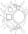
图3A是图1中医疗装置的远端的视图。3A is a view of the distal end of the medical device of FIG. 1 .
图3B是图1中医疗装置的一部分的截面图,示出PCB面向近侧的表面。3B is a cross-sectional view of a portion of the medical device of FIG. 1 showing the proximal-facing surface of the PCB.
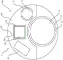
图3C是另一实施例的医疗装置的远端的视图。3C is a view of the distal end of another embodiment medical device.
图3D是另一实施例的医疗装置的远端的视图。Figure 3D is a view of the distal end of a medical device of another embodiment.
图4A是根据一个实施例的PCB的远侧表面的视图。Figure 4A is a view of the distal surface of a PCB according to one embodiment.
图4B是根据另一实施例的PCB的远侧表面的视图。Figure 4B is a view of the distal surface of a PCB according to another embodiment.
具体实施方式Detailed ways
现在将详细参考本公开的各方面,其示例在附图中示出。在可能的情况下,图中将使用相同或相似的附图标记来指代相同或类似的部件。术语“远侧”是指将装置引入受试者(例如患者)时离使用者最远的部分。相比之下,术语“近侧”是指将装置放入受试者体内时离使用者最近的部分。Reference will now be made in detail to aspects of the present disclosure, examples of which are illustrated in the accompanying drawings. Wherever possible, the same or similar reference numbers will be used in the drawings to refer to the same or like parts. The term "distal" refers to the part of the device that is furthest from the user when introduced into the subject (eg, patient). In contrast, the term "proximal" refers to the part of the device that is closest to the user when placed in the subject.
前述一般描述和下面的详细描述都只是示例性和解释性的,并不是对所要求保护的特征的限制。如本文使用的,术语“包括”、“包含”、“具有”、“具备”或其其他变体旨在涵盖非排他性包含物,使得包括元素列表的过程、方法、物品或装置不仅包括这些元素,还可包括未明确列出的或此类过程、方法、物品或装置固有的其他元素。在本公开中,相关术语,例如“大约”、“实质上”、“一般”和“近似”,用于指示所述值或特性的±10%的可能变化。Both the foregoing general description and the following detailed description are exemplary and explanatory only and are not restrictive of what is claimed. As used herein, the terms "comprises," "comprising," "has," "having," or other variations thereof, are intended to cover a non-exclusive inclusion such that a process, method, article, or apparatus that includes a list of elements includes not only those elements , may also include other elements not expressly listed or inherent in such process, method, article, or apparatus. In this disclosure, relative terms such as "about", "substantially", "generally" and "approximately" are used to indicate a possible variation of ±10% of the stated value or characteristic.
本公开的实施例可解决本领域的一个或多个限制。然而,本公开的范围由所附权利要求而不是解决特定问题的能力限定。本公开涉及一种医疗装置,该医疗装置包括成像器、在成像装置的远侧部分中的印刷电路板(PCB),以及覆盖医疗装置的远侧部分的包覆成型。例如,医疗装置可以是任何成像镜(例如,支气管镜、十二指肠镜、内窥镜、结肠镜、输尿管镜等)、导管、工具、仪器等,其具有从手柄向远侧延伸到装置远侧部分的轴。在一些实施例中,轴可以是包括例如用于流体、缆线和用于工作通道中的工具的多个单独通道的多腔挤压件。因此,轴可用作各种管道或通道的护套。多腔挤出件的管腔数量没有特别限制。同样,工作通道可在所述轴的管腔内从手柄向远侧延伸。工作通道可以是多腔挤出件的通道,或者可以是通道内任何合适材料的管道,并且工作通道配置为接收至少一个辅助装置。在一些情况下,管道可向远侧延伸越过轴的远端。Embodiments of the present disclosure may address one or more limitations in the art. However, the scope of the present disclosure is defined by the appended claims rather than the ability to solve specific problems. The present disclosure relates to a medical device comprising an imager, a printed circuit board (PCB) in a distal portion of the imaging device, and an overmold covering the distal portion of the medical device. For example, the medical device can be any imaging scope (e.g., bronchoscope, duodenoscope, endoscope, colonoscope, ureteroscope, etc.), catheter, tool, instrument, etc., which has shaft of the distal portion. In some embodiments, the shaft may be a multi-lumen extrusion including multiple individual channels, eg, for fluids, cables, and tools for the working channel. Therefore, the shaft can be used as a sheath for various pipes or channels. The number of lumens of the multi-lumen extrusion is not particularly limited. Likewise, a working channel may extend distally from the handle within the lumen of the shaft. The working channel may be a channel of a multi-lumen extrusion, or may be a conduit of any suitable material within the channel, and the working channel is configured to receive at least one auxiliary device. In some cases, the conduit can extend distally beyond the distal end of the shaft.
PCB没有特别限制,可以是配置为填有电气部件的任何合适的板。例如,PCB可以是任何标准的单面或双面PCB,并且PCB可通过任何合适的方式填有部件,例如表面安装技术(SMT)。在另一个示例中,PCB可包括多层陶瓷芯片电容器(MLCC)特性,允许电容器或其他电气部件嵌入到PCB中。在其他示例中,PCB可进一步包括焊盘或任何其他类似装置,以允许将导线焊接到PCB。PCB可以是任何合适的形状(例如圆形)以及尺寸(例如2mm至3.4mm的厚度),这允许PCB包覆成型(如下面进一步讨论的)。固定在PCB一侧或两侧上的电气部件可包括任何合适的成像部件、光源部件、电容器、传感器、加速度计、探针、激光器和任何其他合适的可视化、照明或诊断或治疗部件。The PCB is not particularly limited and may be any suitable board configured to be populated with electrical components. For example, the PCB can be any standard single-sided or double-sided PCB, and the PCB can be populated with components by any suitable means, such as surface mount technology (SMT). In another example, the PCB may include a multilayer ceramic chip capacitor (MLCC) feature, allowing capacitors or other electrical components to be embedded into the PCB. In other examples, the PCB may further include pads or any other similar means to allow soldering of wires to the PCB. The PCB may be of any suitable shape (eg circular) and size (eg thickness of 2mm to 3.4mm), which allows for PCB overmolding (as discussed further below). Electrical components mounted on one or both sides of the PCB may include any suitable imaging components, light source components, capacitors, sensors, accelerometers, probes, lasers and any other suitable visualization, lighting or diagnostic or therapeutic components.
PCB可放置在轴的远端内,邻近轴的远端定位,或者可相对于轴的远端位于远侧。PCB可包括开口和/或形状或曲率,以适应在轴内延伸的管道、通道或缆线或以其他方式与之对准。开口可具有任何合适的尺寸或形状,以允许轴的管道或通道与开口对准或以其他方式与开口流体连通。在一些情况下,开口可具有任何合适的尺寸或形状,以允许管道或通道向远侧延伸越过PCB。The PCB can be placed within the distal end of the shaft, positioned adjacent to the distal end of the shaft, or can be located distally relative to the distal end of the shaft. The PCB may include openings and/or a shape or curvature to accommodate or otherwise align with conduits, channels or cables extending within the shaft. The opening may be of any suitable size or shape to allow the conduit or channel of the shaft to align with or otherwise be in fluid communication with the opening. In some cases, the opening may have any suitable size or shape to allow the conduit or channel to extend distally beyond the PCB.
PCB固定到轴的远端的方式没有特别限制。例如,轴的外表面,例如轴的面向远侧的表面,可被环氧树脂胶合或通过任何合适的方式固定在PCB上。此外,装置的缆线,例如操纵缆线,可焊接到PCB的表面,例如面向远侧的表面上,从而提供进一步的固定。还可实施夹具,例如模制的硅树脂或光学透明的环氧树脂,以帮助将PCB固定到医疗装置的远侧部分上这一过程。The manner in which the PCB is fixed to the distal end of the shaft is not particularly limited. For example, the outer surface of the shaft, such as the distal-facing surface of the shaft, may be epoxy glued or secured to the PCB by any suitable means. Additionally, cables of the device, such as steering cables, may be soldered to a surface of the PCB, such as the distal facing surface, thereby providing further fixation. Clamps, such as molded silicone or optically clear epoxy, may also be implemented to aid in the process of securing the PCB to the distal portion of the medical device.
包覆成型可覆盖并粘附到医疗器械的远侧部分。这可包括装置远侧末端的一部分、PCB、和轴的远侧部分。包覆成型的材料没有特别限制,可以是任何合适的生物相容性材料。例如,包覆成型可以是光学透明材料或环氧树脂。包覆成型可充分粘附到医疗装置的远侧部分上,以在穿过各种体腔时承受典型的磨损和摩擦。如在上述材料实例中指出的,包覆成型可以是光学透明的材料,使得成像部件继续通过包覆成型层提供清晰的图像馈送,并且光部件有效地照射通过该层。此外,包覆成型可成形或模制成使得其适应于相对于轴的轴线、工作通道和/或PCB以任何角度固定的成像器。Overmolding covers and adheres to the distal portion of the medical device. This may include a portion of the device's distal tip, the PCB, and the distal portion of the shaft. The overmolded material is not particularly limited, and may be any suitable biocompatible material. For example, the overmold can be an optically clear material or epoxy. The overmold adheres sufficiently to the distal portion of the medical device to withstand typical wear and friction when passing through various body lumens. As noted in the material examples above, the overmold may be an optically transparent material such that the imaging component continues to provide a clear image feed through the overmolded layer, and the light component efficiently shines through the layer. Furthermore, the overmolding may be shaped or molded such that it accommodates the imager being fixed at any angle relative to the axis of the shaft, the working channel and/or the PCB.
包覆成型层通常不覆盖包括一个或多个工作通道和流体通道和/或管道的轴的面向远侧的表面的部分。然而,在某些情况下,包覆成型层可进一步包括在远侧末端处与流体通道和/或工作通道对准的开口,并允许流体或器械通过。此外,在一些实施例中,包覆成型还可包括用于成像部件的开口。包覆成型可与管道和/或通道的外表面齐平,从而将装置的剩余远侧部分与外部环境隔离。包覆成型可包含电子器件并包住它们以使电子器件与生理盐水和其他流体隔离。因此,包覆成型可有效地密封PCB和其他电子部件以防止流体进入。由于包覆成型材料和结构的一些灵活性,包覆成型也可为电子部件提供应力消除。在一些实施例中,包覆成型的面向远侧的表面也可具有特定的形状。例如,面向远侧的表面可具有弯曲形状,该弯曲形状允许来自PCB上的照明源增强的或聚焦的光散射模式。包覆成型还可用作PCB上照明源的散热器,将热量从医疗装置的远侧末端传导出去。包覆成型的厚度没有特别限制,可针对形状、光传输、散热、可制造性、成本等进行优化。The overmolded layer typically does not cover portions of the distal-facing surface of the shaft including the one or more working and fluid channels and/or tubing. However, in some cases, the overmold layer may further include openings at the distal tip that align with the fluid channel and/or the working channel and allow passage of fluid or instruments. Additionally, in some embodiments, the overmold may also include openings for imaging components. The overmolding can be flush with the outer surface of the tubing and/or channel, thereby isolating the remaining distal portion of the device from the external environment. Overmolding can contain the electronics and encase them to isolate the electronics from saline and other fluids. Thus, overmolding effectively seals PCBs and other electronic components from fluid ingress. Overmolding can also provide stress relief for electronic components due to some flexibility in overmolding materials and construction. In some embodiments, the distal-facing surface of the overmold may also have a specific shape. For example, the distal-facing surface may have a curved shape that allows for an enhanced or focused light scattering pattern from an illumination source on the PCB. Overmolding can also act as a heat sink for the illumination source on the PCB, conducting heat away from the distal tip of the medical device. The thickness of the overmolding is not particularly limited and can be optimized for shape, light transmission, heat dissipation, manufacturability, cost, etc.
上述医疗装置的制造工艺没有特别限制。该装置的远侧部分包括合适的PCB,该PCB包括安装在所述PCB上的各种期望的电子部件。如上所述,PCB可具有任何合适的形状,例如,半环形形状。然后可通过任何合适的方式将PCB装配到轴的远端上,例如MLE。例如,PCB可粘附或固定在MLE的面向远侧的表面上。在固定之前,MLE可被修剪或成形以更好地适应PCB,使得PCB和轴的面向远侧的表面对齐/平面化。在另一个示例中,轴可具有略微突出超过轴的远侧表面的唇部或边缘,并且PCB可装配在唇部或边缘内。缆线(例如在轴的管腔内延伸的操纵缆线)可固定(例如焊接)到PCB上,从而进一步将PCB固定到医疗装置上。在通过任何合适的方式将PCB联接到轴上之后,可将装置的至少远侧部分放置或装配在模制固定件内,例如模制硅固定件。模制固定件可成形为使得只有用于包覆成型的期望区域可暴露于包覆成型材料的注射成型。可在所述期望区域周围分配包覆成型,然后可进行一系列固化和/或烘烤程序以硬化包覆成型。在将包覆成型应用于装置的整个远侧面的情况下,杆可插入通道和/或管的开口内。可在应用包覆成型之后移除杆,以形成用于器械和/或流体通过的开口。The manufacturing process of the above-mentioned medical device is not particularly limited. The distal portion of the device includes a suitable PCB including the various desired electronic components mounted on said PCB. As mentioned above, the PCB may have any suitable shape, for example, a semi-circular shape. The PCB may then be fitted to the distal end of the shaft by any suitable means, such as an MLE. For example, a PCB may be adhered or fixed on the distal-facing surface of the MLE. Prior to fixation, the MLE may be trimmed or shaped to better fit the PCB so that the distal-facing surfaces of the PCB and shaft are aligned/planarized. In another example, the shaft may have a lip or rim that protrudes slightly beyond the distal surface of the shaft, and the PCB may fit within the lip or rim. Cables, such as steering cables extending within the lumen of the shaft, may be secured (eg, soldered) to the PCB, thereby further securing the PCB to the medical device. After coupling the PCB to the shaft by any suitable means, at least the distal portion of the device may be placed or fitted within a molded fixture, such as a molded silicon fixture. The molded fixture may be shaped such that only desired areas for overmolding may be exposed to injection molding of the overmolding material. The overmold may be dispensed around the desired area, and then a series of curing and/or baking procedures may be performed to harden the overmold. Where overmolding is applied to the entire distal side of the device, the rod can be inserted into the opening of the channel and/or tube. The stem may be removed after the overmolding has been applied to form openings for the passage of instruments and/or fluids.
参考图1A,示出根据一个实施例的医疗装置1,例如成像镜。医疗装置1包括轴40(例如,导管)和联接到轴40的近侧部分的手柄30。手柄30没有特别限制,可以是任何合适的成像装置手柄。例如,手柄30可包括用于致动或控制医疗装置1以及与医疗装置1相关联的任何工具或装置的至少一个部件。轴40可从手柄30延伸到医疗装置1的远侧部分10。如上所述,轴40可以是任何合适的生物相容性和柔性轴。如图1所示,轴40可以是多腔挤压件,其包括多个腔以容纳各种单独的通道或缆线,例如电气缆线18、冲洗/抽吸管16、缆线14和工作通道12。Referring to Fig. 1A, there is shown a
电气缆线18可以是接收和包覆来自安装在PCB100上的电气部件的至少一根电线(未示出)的任何合适的缆线(下面将进一步详细讨论)。因此,缆线18可从手柄30或外部电源(正电压、接地电压和/或负电压)向远侧延伸到电气部件,例如PCB100的成像器120和光源140a、140b。缆线18可以是绝缘材料,并可包括用于接收至少一根导线的至少一个管腔(未示出)。成像器120、光源140a和光源140b中的每一个可以有单独的导线。
管16可以是用于冲洗或抽吸目的的任何合适管。例如,管16可以是生理盐水冲洗管。管16包括通道17,通过通道17提供冲洗或抽吸。管16可从手柄30或外部部件向远侧延伸,并可向远侧延伸越过PCB100,如图1A所示。
缆线14可以是任何合适的缆线,例如,Bowden缆线,其配置为帮助操纵装置1的远侧部分10。可以有任何合适数量的缆线14,例如一根、两根、三根或四根缆线14(图1A中示为两根)。每个缆线14的远端可在对应的开口101处固定地连接到PCB100。如本领域已知的,每个缆线14的近端可固定至手柄30的致动器。致动器的致动将推动或拉动缆线14,导致轴40的远侧部分在左、右、上和/或下的方向上铰接。轴40可包括在轴40的远端处的铰接接头,该铰接接头具有足够的弯曲灵活性。The
此外,缆线14中的一个或多个还可配置为从电源汲取电流,以向PCB上的电气部件供电,例如灯140a、140b,其可能需要与其他电气部件(例如成像器120)不同的电压。因此,缆线14可以是任何合适的材料,并且在一些情况下,可以是导电材料,例如医用级不锈钢。当配置为承载电流时,缆线14可以是20-50规格的电线,但不限于此。此外,当导电时,缆线14可进一步包括围绕导电缆线的绝缘护套。如前所述,缆线14可从手柄30的一部分向远侧延伸,手柄30配置为控制远侧部分10的转向和/或电源(正电压、接地电压和/或负电压),并且缆线14的远端可通过设置在PCB100上的缆线开口101固定到PCB100上。为了电连接的目的,每个缆线开口101可镀有导电材料114。缆线14至缆线开口101的固定可通过任何合适的方式,例如,用导电环氧树脂焊接或紧固。Additionally, one or more of
在图1A中,工作通道12可以是任何合适的管道,具有从通道12的近端延伸到远端的至少一个管腔13。工作通道12可配置为经由管腔13接收至少一个辅助装置。管腔13的尺寸(例如直径)没有特别限制,例如可以为约1.20mm–1.65mm。通道12可从手柄30延伸到装置1的远侧部分10,并在其远端具有开口。In FIG. 1A , working
医疗装置1的远侧部分10包括PCB100和包覆成型件20。PCB100是半圆形或半环形的,包括面向远侧的表面110a(如图1A和3A所示)和面向近侧的表面110b(如图3B所示),电气部件可安装在该表面上。PCB100可具有与图4A-4B中所示PCB类似的形状。PCB100可相对于轴40在远侧,在轴40的远端内,或者邻近轴40的远端。如图1A所示,PCB100邻近轴40的远端,并通过粘合剂或环氧树脂固定到所述远端。PCB100的半环形形状具有径向向内弯曲的边缘以适应通道12。此外,PCB100包括多个用于接收缆线14的开口101。在下文中,当参考图3A-3D时,将更详细地描述PCB100。The
包覆成型20是覆盖远侧部分10的一部分的生物相容性层或基底。所述部分包括PCB100的至少一部分或全部。包覆成型20粘附到轴40的远侧部分上,并可覆盖PCB100和安装于其上暴露于外部环境的电子部件(例如,成像器120、光源140a、140b和电容器160a、160b)的所有部分。包覆成型20由此起到防止任何流体进入的密封作用。需要注意的是,在其他实施例中,包覆成型20可以不向近侧延伸越过PCB100至轴40的远侧部分。然而,至轴40的这种粘附可进一步帮助保持PCB100邻近轴40的远端,并更好地起到密封件的作用。包覆成型20在光学上是透明的,以允许来自灯140a、140b的照明在感兴趣的波长上的最大透射。此外,包覆成型20面向远侧的部分可以是弯曲的,以适应成像器120和光源140a、140b的突起。如上所述,包覆成型20可以是弯曲的或成形为适应相对于PCB100以一定角度固定的成像器120,以及来自光源140a、140b增强的或聚焦的光散射模式。值得注意的是,通道12和管16的远侧开口未被包覆成型20覆盖。图2示出远侧部分10的侧面轮廓,以及包覆成型20在远侧部分10周围和之上的定位,包括包覆成型20粘附到轴40的远侧部分上。因此,包覆成型20可覆盖PCB100的所有面向远侧的表面,但不覆盖通道12和管16的远侧开口。
参见图1B,示出装置1的远侧部分10’的另一个实施例。相同的附图标记表示相同的部件。远侧部分10’没有如图1A所示在轴40的多个管腔内延伸的单独的管(例如管12和管16)。相反,轴40的管腔限定了工作通道12’和抽吸/冲洗通道17’。通道12’可限定从通道12’的近端延伸到远端的管腔13’。因此,通道12’和通道17’可在轴40的远端具有远侧开口。Referring to Fig. 1B, another embodiment of the distal portion 10' of the
图3A示出装置1的远端,包括PCB100面向远侧的表面110a和轴40面向远侧的表面。如上所述,缆线14可由衬有导电材料114的缆线开口101(未示出)接收。缆线14可焊接或环氧树脂连接到PCB100的远侧表面110a上。通道12和管16向远侧延伸越过PCB100。然而,如上所述,在一些实施例中,例如装置1’中,轴40的管腔可限定工作通道和冲洗通道。因此,在这样的实施例中,通道的远端是轴40的远端。辅助器械可向远侧延伸穿过管腔13,并且流体和抽吸可通过远侧开口17a、17b从冲洗/抽吸通道17分配。FIG. 3A shows the distal end of the
如图3A所示,PCB100面向远侧的表面110a填有成像器120和灯140a、140b,它们安装在表面110a上。成像器120包括透镜122、阻挡层124和壳体126。透镜122没有特别限制,可以是任何合适的成像透镜或透镜堆叠。阻挡层124可以是施加到成像器120侧表面的涂料、环氧树脂或类似材料。层124可帮助阻挡除了通过透镜122进入的光之外的来自灯140a、140b的光进入成像器120,并减少来自成像器120的成像馈送中的雾度或亮点。需要注意的是,层124可应用于成像器120任意数量的侧表面。壳体126可以是用于容纳成像器120所有部件的任何合适壳体。在其他实施例中,成像器120可不具有层124,仅包括壳体126。在一些其他实施例中,成像器120可没有壳体126,仅包括层124,或者可包括壳体126外部的层124。在其他实施例中,成像器120可进一步包括在透镜122面向远侧的表面的顶部上的盖板(未示出)。盖板可以是不影响图像质量的任何合适材料,例如玻璃或塑料,并可用作透镜122的保护屏障。应注意,当包覆成型20(如图2所示)不覆盖成像器120,而是包括密封成像器120周围的开口时,可实施这种盖板。在其他实施例中,成像器120可包括盖,包覆成型20可形成于盖上。As shown in FIG. 3A, the distal-facing
灯140a、140b可以是任何合适的照明源,例如LED。从灯140a、140b发射的光可以是任何合适的波长,例如白光、红外光等。如图3A所示,灯140a和140b在成像器120的相对侧上。然而,要注意的是,成像器120和灯140a、140b的布置或定位没有特别限制,可以是任何合适的布置。面向远侧的表面110a还可包括其他各种部件,例如焊盘和连接器,其可改善组装和连接。The
图3B以装置1的截面示出PCB100的近侧表面110b和轴40的一部分。相同的附图标记表示相同的部件。面向近侧的表面110b填有电容器160a、160b。电容器160a、160b可以是任何合适的电容器,例如去耦电容器。在一些实施例中,电容器160a、160b的一个端子(未示出)可提供至成像器120的电压连接,而电容器160a、160b的另一端子(未显示)提供至成像器120的接地连接。因此,电容器160a、160b可保持电荷以帮助成像器120的电压保持稳定,这又有助于成像器120的图像质量。电容器160a、160b可具有任何合适的尺寸和厚度。电容器160a、160b可具有可忽略的厚度,使得PCB100的近侧表面110b可邻近轴40的远侧表面。还应注意,电容器160a、160b的布置或定位没有特别限制,可与图3B中所示的不同。此外,电容器的数量,例如一个、两个、三个等,也没有特别限制。FIG. 3B shows a portion of the
面向近侧的表面110b进一步填有电气缆线18。面向近侧的表面110b可进一步包括焊盘118,其可制造为PCB100的一部分。焊盘118可焊接至缆线18的各种电线,这些电线可电连接到各种部件,例如成像器120、灯140a、140b(未示出)。The proximal facing
PCB100不限于上面讨论的各种电子部件、配置和尺寸,参见图3A和3B。图3C和3D示出包括不同部件和布局的附加PCB实施例(100’,100”)。相同的附图标记表示相同的部件。如图3C所示,PCB100’包括一个灯140,还包括第二通道18。第二通道18包括管腔19。管腔19的尺寸(例如直径)没有特别的限制。附加辅助器械/装置可向远侧延伸穿过管腔19。附加的辅助装置没有特别限制,可包括例如激光探针、电液碎石(EHL)探针、光谱仪、电磁传感器或超声波传感器。第二通道18的存在可允许医生同时接近和使用主要器械,例如钳子或取回装置,以及附加辅助器械。
如图3D所示,PCB100”也可没有上面讨论的一些电气部件。PCB100”没有管16和缆线14(示于图3A和3C中)。因此,PCB100”和轴40可具有更小的直径,这在某些情况下可能是医生的首选。图3C和3D示出印刷电路板(例如PCB100’、100”)的可定制性质,以及如何定制该板以适应医生的各种目的和需求。As shown in Figure 3D,
图4A和4B示出PCB100面向远侧的表面110a。相同的附图标记表示相同的部件。此外,图4A和4B示出导电时缆线14(现在由14a、14b区分)与灯140a、140b之间的电连接。如上所述,缆线14a、14b可通过包括导电镀层114a、114b的缆线开口101(未示出)焊接或环氧树脂连接到PCB100。导电镀层114a、114b勾勒出缆线开口的周边,从而围绕缆线14a、14b。由缆线14a、14b汲取的电流可由镀层114a、114b接收,镀层114a和114b继而将电流引向灯140a、140b。4A and 4B illustrate the distal-facing
图4A示出在缆线14a、灯140a、140b和缆线14b之间的串行PCB路径的示例。如图所示,缆线14a连接到导电镀层114a,该导电镀层通过延伸至第一连接点(例如端子142a)的第一导电迹线141a连接到灯140a。灯140a还包括第二连接点144a。第二连接点144a经由延伸至灯140b的第二连接点144b的第二导电迹线141b连接到灯140b。灯140b的第一连接点142b经由连接到缆线14b的第三导电迹线141c连接到导电镀层114b。应注意,上述灯140a、140b的第一和第二连接点142a、144a、142b和144b中的每一个都衬有用于连接目的的导电镀层1140a、1140b。例如,可在PCB100中制造用于灯140a、140b上述连接点的导电镀层1140a、1140b。在该实施例中,镀层1140b可用作电压源,而镀层1140a用作电接地。例如,缆线14b可向镀层1140b施加6V,由于串行路径,这将导致向两个灯140a、140b提供3V。Figure 4A shows an example of a serial PCB path between
图4B示出缆线14a、灯140a、140b和缆线14b之间的并行PCB路径的示例。如图所示,缆线14a连接到导电镀层1140a,该导电镀层通过延伸至第一连接点142a的第一导电迹线141a连接到灯140a。灯140a还包括第二连接点144a和第三连接点146a。在灯140a和灯140b之间存在并联连接,因为第二连接点144a和第三连接点146a分别经由导电迹线141b、141c与灯140b的第二连接点144b和第三连接点146b连接。要注意的是,上述灯140a、140b的第一、第二和第三连接点142a、144a、146a、142b、144b和146b中的每一个都衬有用于连接目的的导电镀层1140a、1140b。例如,可在PCB100中制造用于灯140a、140b的上述连接点的导电镀层1140a、1140b。在该实施例中,镀层1140b可用作电压源,而镀层1140a用作电接地。例如,缆线14b可向镀层114b施加3V,由于并行路径,这将导致向两个灯140a、140b提供3V。Figure 4B shows an example of a parallel PCB path between
应注意,缆线14a、14b不限于为灯140a、140b供电,并可向PCB100的其他各种电气部件提供电流。如果提供了额外的电接地,缆线14a、14b可为两个单独的装置电压供电,或者缆线14a、14b提供单个装置电压供应和接地。It should be noted that the
对本领域技术人员来说显而易见的是,在不脱离本公开范围的情况下,可对所公开的装置进行各种修改和变化。通过考虑本文公开的本发明的说明书和实践,本公开的其他实施例对于本领域技术人员将是显而易见的。本说明书和实施例仅认为是示例性的,本发明的真正范围和实质由以下权利要求指示。It will be apparent to those skilled in the art that various modifications and changes can be made in the disclosed apparatus without departing from the scope of the present disclosure. Other embodiments of the disclosure will be apparent to those skilled in the art from consideration of the specification and practice of the invention disclosed herein. The specification and examples are considered exemplary only, with a true scope and spirit of the invention being indicated by the following claims.
Claims (15)
Translated fromChineseApplications Claiming Priority (3)
| Application Number | Priority Date | Filing Date | Title |
|---|---|---|---|
| US202063083151P | 2020-09-25 | 2020-09-25 | |
| US63/083,151 | 2020-09-25 | ||
| PCT/US2021/071509WO2022067301A1 (en) | 2020-09-25 | 2021-09-20 | Medical imaging device |
Publications (1)
| Publication Number | Publication Date |
|---|---|
| CN116419706Atrue CN116419706A (en) | 2023-07-11 |
Family
ID=78086185
Family Applications (1)
| Application Number | Title | Priority Date | Filing Date |
|---|---|---|---|
| CN202180075227.0APendingCN116419706A (en) | 2020-09-25 | 2021-09-20 | medical imaging device |
Country Status (4)
| Country | Link |
|---|---|
| US (2) | US11896199B2 (en) |
| EP (1) | EP4216795A1 (en) |
| CN (1) | CN116419706A (en) |
| WO (1) | WO2022067301A1 (en) |
Families Citing this family (12)
| Publication number | Priority date | Publication date | Assignee | Title |
|---|---|---|---|---|
| DE102018208538A1 (en) | 2018-05-30 | 2019-12-05 | Kardion Gmbh | Intravascular blood pump and process for the production of electrical conductors |
| DE102018208539A1 (en) | 2018-05-30 | 2019-12-05 | Kardion Gmbh | A motor housing module for sealing an engine compartment of a motor of a cardiac assist system and cardiac assistance system and method for mounting a cardiac assist system |
| DE102018208879A1 (en) | 2018-06-06 | 2020-01-30 | Kardion Gmbh | Method for determining a total fluid volume flow in the area of an implanted, vascular support system |
| DE102018208929A1 (en) | 2018-06-06 | 2019-12-12 | Kardion Gmbh | A method of determining a flow rate of fluid flowing through an implanted vascular support system |
| DE102018208862A1 (en) | 2018-06-06 | 2019-12-12 | Kardion Gmbh | Implantable vascular support system |
| DE102018208936A1 (en) | 2018-06-06 | 2019-12-12 | Kardion Gmbh | Determining device and method for determining a viscosity of a fluid |
| DE102018208899A1 (en) | 2018-06-06 | 2019-12-12 | Kardion Gmbh | A method for determining the speed of sound in a fluid in the region of an implanted vascular support system |
| DE102018208945A1 (en) | 2018-06-06 | 2019-12-12 | Kardion Gmbh | An analysis device and method for analyzing a viscosity of a fluid |
| DE102018208913A1 (en) | 2018-06-06 | 2019-12-12 | Kardion Gmbh | A method of operating an implanted ventricular assist device |
| DE102018208933A1 (en) | 2018-06-06 | 2019-12-12 | Kardion Gmbh | A method of determining a flow rate of fluid flowing through an implanted vascular support system |
| DE102018210076A1 (en) | 2018-06-21 | 2019-12-24 | Kardion Gmbh | Method and device for detecting a state of wear of a cardiac support system, method and device for operating a cardiac support system and cardiac support system |
| US12178391B2 (en)* | 2023-02-10 | 2024-12-31 | Evoendo, Inc. | Endoscopy device having an electrical control system |
Citations (4)
| Publication number | Priority date | Publication date | Assignee | Title |
|---|---|---|---|---|
| US20130131451A1 (en)* | 2011-11-18 | 2013-05-23 | Invendo Medical Gmbh | Medical endoscope with a cooling device for mounted electric components |
| CN109998449A (en)* | 2016-03-31 | 2019-07-12 | 柯惠有限合伙公司 | Thoracic endoscope for surface scanning |
| CN209417411U (en)* | 2018-12-12 | 2019-09-20 | 荣晶生物科技股份有限公司 | Endoscope device and its cable assembly |
| WO2020121435A1 (en)* | 2018-12-12 | 2020-06-18 | オリンパス株式会社 | Endoscope tip and endoscope |
Family Cites Families (19)
| Publication number | Priority date | Publication date | Assignee | Title |
|---|---|---|---|---|
| US20060146172A1 (en)* | 2002-03-18 | 2006-07-06 | Jacobsen Stephen C | Miniaturized utility device having integrated optical capabilities |
| US7591780B2 (en)* | 2002-03-18 | 2009-09-22 | Sterling Lc | Miniaturized imaging device with integrated circuit connector system |
| DE10254609B4 (en)* | 2002-11-22 | 2017-12-07 | Stm Medizintechnik Starnberg Gmbh | endoscope head |
| US20060041188A1 (en)* | 2003-03-25 | 2006-02-23 | Dirusso Carlo A | Flexible endoscope |
| JP2008532574A (en)* | 2005-01-27 | 2008-08-21 | スーパー ディメンション リミテッド | Endoscope with small imaging device |
| WO2012161021A1 (en)* | 2011-05-20 | 2012-11-29 | オリンパスメディカルシステムズ株式会社 | Endoscope |
| EP2866673B1 (en)* | 2012-07-02 | 2020-03-18 | Koninklijke Philips N.V. | Minimally invasive medical instrument |
| JP6490066B2 (en)* | 2013-07-01 | 2019-03-27 | エンドチョイス インコーポレイテッドEndochoice, Inc. | Circuit board assembly for multi-view element endoscope |
| WO2017143151A1 (en)* | 2016-02-18 | 2017-08-24 | Boston Scientific Scimed, Inc. | Systems with sonic visualization capability |
| US10517470B2 (en)* | 2016-05-13 | 2019-12-31 | Karl Storz Endovision, Inc. | Optical instrument and articulating image sensing apparatus therefor |
| US10485950B2 (en)* | 2017-08-03 | 2019-11-26 | ART MEDICAL Ltd. | Multipurpose cabling |
| US10525232B2 (en)* | 2017-09-06 | 2020-01-07 | Becton, Dickinson And Company | Smart obturator assembly |
| CN111683582A (en)* | 2018-01-03 | 2020-09-18 | 真诺科有限责任公司 | Angled borescope with digital image orientation |
| US11547276B2 (en)* | 2018-03-09 | 2023-01-10 | The Children's Medical Center Corporation | Optical bulb for surgical instrument port |
| US11712294B2 (en)* | 2018-05-25 | 2023-08-01 | Biosense Webster (Israel) Ltd. | Heat transfer through a catheter tip |
| TWI733074B (en)* | 2019-01-09 | 2021-07-11 | 榮晶生物科技股份有限公司 | Microelectronic device and circuit board thereof |
| CN113423321B (en)* | 2019-03-18 | 2024-06-14 | 奥林巴斯株式会社 | Front end frame of endoscope, front end unit and endoscope |
| CN110604535A (en)* | 2019-09-23 | 2019-12-24 | 安翰科技(武汉)股份有限公司 | Capsule nucleus and capsule endoscopy |
| US11153970B1 (en)* | 2020-07-20 | 2021-10-19 | Atl Technology, Llc | Apparatus with electrical components end mounted to printed circuit board |
- 2021
- 2021-09-20CNCN202180075227.0Apatent/CN116419706A/enactivePending
- 2021-09-20WOPCT/US2021/071509patent/WO2022067301A1/ennot_activeCeased
- 2021-09-20EPEP21790051.3Apatent/EP4216795A1/enactivePending
- 2021-09-20USUS17/448,088patent/US11896199B2/enactiveActive
- 2023
- 2023-12-27USUS18/396,860patent/US12402777B2/enactiveActive
Patent Citations (4)
| Publication number | Priority date | Publication date | Assignee | Title |
|---|---|---|---|---|
| US20130131451A1 (en)* | 2011-11-18 | 2013-05-23 | Invendo Medical Gmbh | Medical endoscope with a cooling device for mounted electric components |
| CN109998449A (en)* | 2016-03-31 | 2019-07-12 | 柯惠有限合伙公司 | Thoracic endoscope for surface scanning |
| CN209417411U (en)* | 2018-12-12 | 2019-09-20 | 荣晶生物科技股份有限公司 | Endoscope device and its cable assembly |
| WO2020121435A1 (en)* | 2018-12-12 | 2020-06-18 | オリンパス株式会社 | Endoscope tip and endoscope |
Also Published As
| Publication number | Publication date |
|---|---|
| US11896199B2 (en) | 2024-02-13 |
| WO2022067301A1 (en) | 2022-03-31 |
| US20240122451A1 (en) | 2024-04-18 |
| US20220095887A1 (en) | 2022-03-31 |
| EP4216795A1 (en) | 2023-08-02 |
| US12402777B2 (en) | 2025-09-02 |
Similar Documents
| Publication | Publication Date | Title |
|---|---|---|
| CN116419706A (en) | medical imaging device | |
| US11938662B2 (en) | Tip part assembly for an endoscope | |
| US7955255B2 (en) | Imaging assembly with transparent distal cap | |
| CN106163377B (en) | Medical system and related method for diagnosis and treatment | |
| US12053162B2 (en) | Distal end portion of an endoscope having electronic components and corresponding spaces for wiring and endoscope having the distal end portion | |
| CN106061365A (en) | Solid-state imaging device and electronic endoscope provided with solid-state imaging device | |
| US20160028926A1 (en) | Endoscope apparatus | |
| EP3248536A1 (en) | Heat sink structure and led heat sink assemblies | |
| CN113490449A (en) | Endoscope tip unit and endoscope | |
| WO2008026199A1 (en) | Pcb board for hybrid circuit of an image sensor | |
| CN113164021B (en) | Endoscope front end structure and endoscope | |
| EP3788945A1 (en) | A tip part assembly for an endoscope | |
| US20240115114A1 (en) | Illuminator circuit board assembly for an endoscope | |
| CN105828689A (en) | Imaging device and endoscope device | |
| CN112450853A (en) | Tip assembly for endoscope | |
| CN106061360A (en) | Imaging device and endoscopic device | |
| JP2025523104A (en) | Medical Device Assemblies and Components | |
| JP2007014488A (en) | Endoscope | |
| EP3788939B1 (en) | A tip part assembly for an endoscope and a method of manufacture of a tip part assembly of an endoscope | |
| JP2022179301A (en) | Endoscope imaging device and endoscope | |
| US20250194905A1 (en) | Modular distal assemblies for medical devices and methods of using and making the same | |
| WO2017115441A1 (en) | Mounting structure, image pickup device, and endoscope | |
| EP3788942A1 (en) | A tip part assembly for an endoscope | |
| JPWO2016203535A1 (en) | Endoscope | |
| CN115363511A (en) | Endoscope image pickup device and endoscope |
Legal Events
| Date | Code | Title | Description |
|---|---|---|---|
| PB01 | Publication | ||
| PB01 | Publication | ||
| SE01 | Entry into force of request for substantive examination | ||
| SE01 | Entry into force of request for substantive examination |