CN116416294A - Accurate three-dimensional reconstruction method for object with inconsistent reflectivity - Google Patents
Accurate three-dimensional reconstruction method for object with inconsistent reflectivityDownload PDFInfo
- Publication number
- CN116416294A CN116416294ACN202310685479.6ACN202310685479ACN116416294ACN 116416294 ACN116416294 ACN 116416294ACN 202310685479 ACN202310685479 ACN 202310685479ACN 116416294 ACN116416294 ACN 116416294A
- Authority
- CN
- China
- Prior art keywords
- pixel
- reflectivity
- error
- camera
- scene
- Prior art date
- Legal status (The legal status is an assumption and is not a legal conclusion. Google has not performed a legal analysis and makes no representation as to the accuracy of the status listed.)
- Pending
Links
Images


Classifications
- G—PHYSICS
- G01—MEASURING; TESTING
- G01B—MEASURING LENGTH, THICKNESS OR SIMILAR LINEAR DIMENSIONS; MEASURING ANGLES; MEASURING AREAS; MEASURING IRREGULARITIES OF SURFACES OR CONTOURS
- G01B11/00—Measuring arrangements characterised by the use of optical techniques
- G01B11/24—Measuring arrangements characterised by the use of optical techniques for measuring contours or curvatures
- G01B11/25—Measuring arrangements characterised by the use of optical techniques for measuring contours or curvatures by projecting a pattern, e.g. one or more lines, moiré fringes on the object
- G01B11/254—Projection of a pattern, viewing through a pattern, e.g. moiré
- G—PHYSICS
- G06—COMPUTING OR CALCULATING; COUNTING
- G06T—IMAGE DATA PROCESSING OR GENERATION, IN GENERAL
- G06T17/00—Three dimensional [3D] modelling, e.g. data description of 3D objects
- G—PHYSICS
- G06—COMPUTING OR CALCULATING; COUNTING
- G06T—IMAGE DATA PROCESSING OR GENERATION, IN GENERAL
- G06T7/00—Image analysis
- G06T7/50—Depth or shape recovery
- G06T7/514—Depth or shape recovery from specularities
- G—PHYSICS
- G06—COMPUTING OR CALCULATING; COUNTING
- G06T—IMAGE DATA PROCESSING OR GENERATION, IN GENERAL
- G06T7/00—Image analysis
- G06T7/50—Depth or shape recovery
- G06T7/521—Depth or shape recovery from laser ranging, e.g. using interferometry; from the projection of structured light
- G—PHYSICS
- G06—COMPUTING OR CALCULATING; COUNTING
- G06T—IMAGE DATA PROCESSING OR GENERATION, IN GENERAL
- G06T2200/00—Indexing scheme for image data processing or generation, in general
- G06T2200/08—Indexing scheme for image data processing or generation, in general involving all processing steps from image acquisition to 3D model generation
- Y—GENERAL TAGGING OF NEW TECHNOLOGICAL DEVELOPMENTS; GENERAL TAGGING OF CROSS-SECTIONAL TECHNOLOGIES SPANNING OVER SEVERAL SECTIONS OF THE IPC; TECHNICAL SUBJECTS COVERED BY FORMER USPC CROSS-REFERENCE ART COLLECTIONS [XRACs] AND DIGESTS
- Y02—TECHNOLOGIES OR APPLICATIONS FOR MITIGATION OR ADAPTATION AGAINST CLIMATE CHANGE
- Y02A—TECHNOLOGIES FOR ADAPTATION TO CLIMATE CHANGE
- Y02A90/00—Technologies having an indirect contribution to adaptation to climate change
- Y02A90/10—Information and communication technologies [ICT] supporting adaptation to climate change, e.g. for weather forecasting or climate simulation
Landscapes
- Engineering & Computer Science (AREA)
- Physics & Mathematics (AREA)
- General Physics & Mathematics (AREA)
- Computer Vision & Pattern Recognition (AREA)
- Theoretical Computer Science (AREA)
- Optics & Photonics (AREA)
- Computer Graphics (AREA)
- Geometry (AREA)
- Software Systems (AREA)
- Length Measuring Devices By Optical Means (AREA)
Abstract
Description
Translated fromChinese技术领域technical field
本发明涉及一种反射率不一致物体的精确三维重建方法,属于光学测量技术领域。The invention relates to an accurate three-dimensional reconstruction method for an object with inconsistent reflectivity, and belongs to the technical field of optical measurement.
背景技术Background technique
条纹投影轮廓术(FPP)是一种典型的基于相位的方法,可以建立像素级的图像对应关系并以每秒数千帧的速度感知3-D数据。在FPP中,由于相机的透镜像差和衍射极限,系统点扩散函数(PSF)变得非理想且尺寸有限。正如我们所知,拍摄的强度是每个像素的PSF内部强度的积分,这将偏离其包含不连续反射率的表面区域的实际强度。例如,低反射率区域拍摄的强度将与高反射率区域的强度进行平均,这将在不连续区域周围计算相位阶段产生错误。相位误差将导致建立像素对应的误差,从而产生不可忽略的不连续反射率(DR)误差。Fringe projection profilometry (FPP) is a typical phase-based method that can establish pixel-level image correspondence and perceive 3-D data at thousands of frames per second. In FPP, the system point spread function (PSF) becomes non-ideal and finite in size due to the lens aberration and diffraction limit of the camera. As we know, the captured intensity is the integral of the intensity inside the PSF of each pixel, which will deviate from the actual intensity of its surface region containing the discontinuous reflectance. For example, the intensities taken from areas of low reflectivity will be averaged with the intensities of areas of high reflectivity, which will introduce errors in calculating the phase phase around discontinuities. Phase errors will cause errors in establishing pixel correspondences, resulting in non-negligible discontinuous reflectance (DR) errors.
FPP可以通过先估计PSF分布然后用最近的正确的区域补偿错误区域的方式减少DR误差。这种PSF估计方法均方根高度误差降低到原来的三分之一,但是对有急剧深度变化的物体很难确定正确的区域。最近提出了一种基于反卷积的减少误差的方法,它先校准相机PSF,然后检索所需的相位恢复模式。PSF估计方法最多可将RMS高度误差降低四倍,但其反卷积的振铃效应会在特征细节和深度急剧变化等区域引入波纹误差。FPP can reduce DR errors by first estimating the PSF distribution and then compensating the wrong regions with the nearest correct regions. This PSF estimation method reduces the root mean square height error to one-third of the original, but it is difficult to determine the correct area for objects with sharp depth changes. A deconvolution-based error reduction method was recently proposed that first calibrates the camera PSF and then retrieves the desired phase recovery pattern. The PSF estimation method reduces the RMS height error by up to a factor of four, but the ringing effect of its deconvolution introduces ripple errors in areas such as feature details and sharp depth changes.
通常当PSF标准偏差小于8时,相位误差可以小于0.3rad。如果条纹频率大于0.05,则像素对应误差通常小于测量范围内的一个像素。DR误差与相机PSF的大小成正比,可以通过减轻散焦水平或增加场景的采集分辨率来减少DR误差。因此,我们可以通过选择高分辨率相机直接减小DR误差,但这会大大增加系统成本。此外,如果我们能在场景被投影图案调制之前对相邻像素的不连续反射率进行归一化,则可以检索到所需要的图案,但是很难获得FPP的场景反射率。Usually when the PSF standard deviation is less than 8, the phase error can be less than 0.3rad. If the fringe frequency is greater than 0.05, the pixel correspondence error is usually less than one pixel within the measurement range. The DR error is proportional to the size of the camera PSF, which can be reduced by mitigating the level of defocus or increasing the acquisition resolution of the scene. Therefore, we can directly reduce the DR error by choosing a high-resolution camera, but this will greatly increase the system cost. Furthermore, if we can normalize the discontinuous reflectance of adjacent pixels before the scene is modulated by the projected pattern, the desired pattern can be retrieved, but it is difficult to obtain the scene reflectance for FPP.
与基于特征和基于相位的3-D重建技术不同,单像素成像测量方法(SIM)通过跟踪相机和投影仪之间的场景强度一致性来建立图像对应关系。通过将每个相机像素视为单像素探测器,SIM投影具有全图像空间频率的图案并在变化域中获取具有全空间频率的光谱分量,可以通过逆变换重建场景反射率。重建场景是相机PSF和反射光的卷积,所需像素坐标是重建场景的灰度中心。当相机PSF包含不连续反射率的时候,灰度中心会向偏向分辨率高的区域。因此引入了图像对应错误并导致DR误差。Unlike feature-based and phase-based 3-D reconstruction techniques, single-pixel imaging measurements (SIM) establish image correspondence by tracking the consistency of scene intensity between cameras and projectors. By treating each camera pixel as a single-pixel detector, SIM projects patterns with full image spatial frequencies and acquires spectral components with full spatial frequencies in the variation domain, scene reflectance can be reconstructed by inverse transformation. The reconstructed scene is the convolution of the camera PSF and the reflected light, and the required pixel coordinate is the gray center of the reconstructed scene. When the camera PSF contains discontinuous reflectance, the gray center will be biased towards the high-resolution area. Image correspondence errors are thus introduced and lead to DR errors.
如前所述,通过在计算对应像素之前对重建场景不连续反射率进行归一化,可以降低DR误差。每个相机像素的重建场景反射率的总和是调制的投影仪光强度,它与场景反射率成正比。因此,对每个相机像素的拍摄场景反射率进行归一化能够降低DR误差。然而,传统的SIM由于编码模式众多,例如数千帧,会非常耗时。As mentioned earlier, DR errors can be reduced by normalizing the reconstructed scene discontinuity reflectance before computing the corresponding pixels. The sum of the reconstructed scene reflectance for each camera pixel is the modulated projector light intensity, which is proportional to the scene reflectance. Therefore, normalizing the captured scene reflectance for each camera pixel can reduce DR errors. However, traditional SIM would be very time-consuming due to numerous encoding modes, such as thousands of frames.
总之,FPP具有更高效率,但是会引入DR误差。而SIM需要较长的采集时间,但展示了显示出更精准的3-D测量的潜力。In summary, FPP is more efficient, but introduces DR errors. SIM, on the other hand, requires longer acquisition times but demonstrates the potential for more accurate 3-D measurements.
发明内容Contents of the invention
为了解决上述技术问题,本发明公开了一种反射率不一致物体的精确三维重建方法,构建了FPP和SIM的DR误差模型,通过反射率归一化来补偿SIM的DR误差。由于SI的采集时间极长,我们采用并行单像素成像技术,并使用FPP建立像素级对应,以加速数据采集。其具体技术方案如下:In order to solve the above technical problems, the present invention discloses an accurate three-dimensional reconstruction method for objects with inconsistent reflectivity, constructs DR error models of FPP and SIM, and compensates SIM DR errors by normalizing reflectivity. Due to the extremely long acquisition time of SI, we employ parallel single-pixel imaging techniques and use FPP to establish pixel-level correspondence to speed up data acquisition. Its specific technical scheme is as follows:
一种反射率不一致物体的精确三维重建方法,包括以下步骤:An accurate three-dimensional reconstruction method for an object with inconsistent reflectivity, comprising the following steps:
一、通过投影仪将一组相移的正弦条纹图案投射到被测物体上,并通过相机捕获从所述被测物体表面反射的相移正弦条纹图案;1. Projecting a group of phase-shifted sinusoidal fringe patterns onto the measured object through a projector, and capturing the phase-shifted sinusoidal fringe patterns reflected from the surface of the measured object through a camera;
二、基于相机捕获的相移正弦条纹图案,通过相移和相位展开获得绝对相位,使用FPP建立粗糙像素对应关系;2. Based on the phase-shifted sinusoidal fringe pattern captured by the camera, the absolute phase is obtained through phase shift and phase unwrapping, and the rough pixel correspondence is established using FPP;
三、通过投影仪将一组哈达玛条纹图案投射到被测物体上,并通过相机捕获从所述被测物体表面反射的哈达玛条纹图案;3. Project a set of Hadamard fringe patterns onto the measured object through a projector, and capture the Hadamard fringe patterns reflected from the surface of the measured object through a camera;
四、基于相机捕获的哈达玛条纹图案,使用哈达玛逆变换获得产生误差的亚像素坐标,计算出拍摄物体反射率,并建立亚像素对应关系;4. Based on the Hadamard fringe pattern captured by the camera, use Hadamard inverse transformation to obtain the sub-pixel coordinates of the error, calculate the reflectivity of the photographed object, and establish the sub-pixel correspondence;
五、在SIM单像素成像技术中,计算每个相机像素捕捉的场景反射率,并计算出投影仪拍摄的物体反射率,对拍摄的反射率进行归一化,并对像素对应误差进行补偿。5. In the SIM single-pixel imaging technology, the reflectance of the scene captured by each camera pixel is calculated, and the reflectance of the object captured by the projector is calculated, the reflectance of the capture is normalized, and the error corresponding to the pixel is compensated.
进一步地,所述步骤一中相机的像素唯一对应具有相同相位的投影仪的像素,设定正弦条纹图案的场景点


其中,A和B分别表示条纹背景和振幅,

进一步地,所述步骤二的绝对相位为Further, the absolute phase of the second step is

其中,
所述粗糙像素对应关系建立为The rough pixel correspondence is established as

其中,uc和vc表示投影仪像素级坐标对应关系,round表示取整运算符,U和V代表投影仪分辨率。Among them, uc and vc represent the pixel-level coordinate correspondence of the projector, round represents the rounding operator, and U and V represent the resolution of the projector.
进一步地,所述步骤三中使用哈达玛基础模式重建场景反射率和初始像素,哈达玛基础模式


其中,(m,n)是哈达玛域中的坐标,m0,n0分别表示沿(m,n)方向的符号变化次数,
特别地,选择16*16像素的哈达玛矩阵来覆盖每个相机像素的可见区域。因此,使用一系列具有像素周期的周期性扩展模式来加速采集,测量所需的哈达玛基础模式为512帧。In particular, a Hadamard matrix of 16*16 pixels is chosen to cover the visible area of each camera pixel. Therefore, using a series of periodically extended patterns with a pixel period to speed up the acquisition, the Hadamard base pattern required for the measurement is 512 frames.
进一步地,所述步骤四通过的哈达玛逆变化,获得由一个相机像素拍摄的场景反射率Further, the Hadamard inverse change in

其中,

通过灰度质心法计算反射率不连续而产生误差的亚像素坐标
通过


进一步地,所述步骤五中将拍摄的反射率用

其中,
得出补偿后对应投影仪像素坐标:Get the corresponding projector pixel coordinates after compensation:

补偿后的像素对应误差:Compensated pixel corresponding error:

其中,


本发明首先构建了FPP和SIM的DR误差模型,由此得出结论:SIM的DR误差可以通过反射率归一化来补偿。基于上述结论,提出了一种基于反射率的精确三维重建方法,在不连续反射率下能够减轻DR误差。此外,由于SI的采集时间极长,我们采用并行单像素成像技术,并使用FPP建立像素级对应,以加速数据采集。误差模型和实验结果都验证了所提出的方法可以重建具有不连续反射率的精确3-D形状。The present invention first constructs the DR error models of FPP and SIM, and thus draws a conclusion: the DR error of SIM can be compensated by normalizing the reflectivity. Based on the above conclusions, an accurate 3D reconstruction method based on reflectance is proposed, which can alleviate DR error under discontinuous reflectance. In addition, due to the extremely long acquisition time of SI, we employ parallel single-pixel imaging techniques and use FPP to establish pixel-level correspondence to speed up data acquisition. Both the error model and experimental results validate that the proposed method can reconstruct accurate 3-D shapes with discontinuous reflectance.
有益效果Beneficial effect
与现有技术相比,本发明所提供的一种基于反射率的误差补偿方法,一方面使用FPP建立粗糙像素对应关系,另一方面使用SIM获得亚像素坐标,然后基于反射率归一化进行DR误差去除,有效提高了三维重建的精度。Compared with the prior art, the present invention provides an error compensation method based on reflectivity. On the one hand, FPP is used to establish a rough pixel correspondence, and on the other hand, SIM is used to obtain sub-pixel coordinates, and then normalized based on reflectivity. DR error removal effectively improves the accuracy of 3D reconstruction.
附图说明Description of drawings
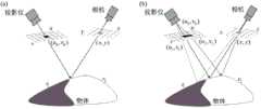
图1为本发明的光传输示意图,(a)为系统PSF理想条件下,(b)为系统PSF非理想条件下;Fig. 1 is a schematic diagram of optical transmission of the present invention, (a) is under ideal system PSF conditions, (b) is under non-ideal system PSF conditions;
图2为本发明提出的基于反射率的精确3-D重建方法的示意图;Fig. 2 is a schematic diagram of the accurate 3-D reconstruction method based on reflectivity proposed by the present invention;
图3为本发明的实验装置示意图;Fig. 3 is a schematic diagram of the experimental device of the present invention;
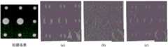
图4为不同拍摄图像分辨率的三维重建结果示意图,(a)为低分辨率,(b)为中分辨率,(c)为高分辨率;Figure 4 is a schematic diagram of the 3D reconstruction results of different captured image resolutions, (a) is low resolution, (b) is medium resolution, and (c) is high resolution;
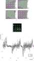
图5为不同投影条纹图案频率的精度评估示意图,(a)为4种不同频率的条纹图测量的三维形状误差图,(b)为一条线的高度误差图;Figure 5 is a schematic diagram of the accuracy evaluation of different projected fringe pattern frequencies, (a) is the three-dimensional shape error map measured by fringe patterns of four different frequencies, (b) is the height error map of a line;
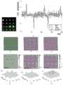
图6为精度估计示意图,(a)为条纹周期20像素的传统FPP、传统SIM和提出的基于反射率的精确3-D重建方法的重建误差对比,(b)为FPP重建的3-D形貌,(c)为传统SIM重建的3-D形貌,(d)为本发明提出的基于反射率的精确3-D重建方法重建的3-D形貌,(e)为FPP重建的3-D形貌的误差分布,(f)传统SIM为重建的3-D形貌的误差分布,(g)为本发明提出的基于反射率的精确3-D重建方法重建的3-D形貌的误差分布;Figure 6 is a schematic diagram of accuracy estimation, (a) is the reconstruction error comparison of traditional FPP with a fringe period of 20 pixels, traditional SIM and the proposed accurate 3-D reconstruction method based on reflectivity, (b) is the 3-D shape reconstructed by FPP (c) is the 3-D topography reconstructed by traditional SIM, (d) is the 3-D topography reconstructed by the accurate 3-D reconstruction method based on reflectivity proposed by the present invention, (e) is the 3-D topography reconstructed by FPP -D error distribution of topography, (f) traditional SIM is the error distribution of reconstructed 3-D topography, (g) is the 3-D topography reconstructed by the accurate 3-D reconstruction method based on reflectivity proposed by the present invention error distribution;
图7为复杂表面物体的三维形状示意图,(a)为拍摄的场景,(b)为由FPP重建的3-D形貌,(c)为本发明提出的基于反射率的精确3-D重建方法重建的3-D形貌。Figure 7 is a schematic diagram of the three-dimensional shape of a complex surface object, (a) is the captured scene, (b) is the 3-D topography reconstructed by FPP, and (c) is the accurate 3-D reconstruction based on reflectivity proposed by the present invention Methods for reconstructing 3-D topography.
实施方式Implementation
现在结合附图对本发明作进一步详细的说明。The present invention is described in further detail now in conjunction with accompanying drawing.
一、FPP误差分析:1. FPP error analysis:
在FPP中,投影仪将一组相移的正弦条纹图案投射到物体上,相机捕捉从物体表面反射的这些图案。相机的每个像素将唯一对应具有相同相位的投影仪像素。这些条纹被设计为In FPP, a projector projects a set of phase-shifted sinusoidal fringe patterns onto an object, and a camera captures these patterns reflected from the object's surface. Each pixel of the camera will uniquely correspond to a pixel of the projector with the same phase. These stripes are designed to

其中,(u,v)表示投影仪坐标,


我们假设当光线从投影仪像素点(u,v)发出并到达相机像素点(x,y),一个相机像素拍摄的场景反射率可以表示为r(u,v,x,y)。那么,相机拍摄的图像可以表示为We assume that when light is emitted from a projector pixel (u, v) and reaches a camera pixel (x, y), the reflectance of a scene captured by a camera pixel can be expressed as r(u, v, x, y). Then, the image captured by the camera can be expressed as

其中U*V代表投影仪分辨率。Where U*V represents the projector resolution.
为了更加清晰,我们在图1中说明了光传输过程。如图1中的(a)所示,当系统PSF理想时,相机像素(x,y)接收到物体表面反射的光,是该物体表面被投影仪像素(u,v)照亮的。但是当系统PSF不理想时,相机像素(x,y)接收物体表面发射的光,是该物体表面被几个邻近的投影仪像素照亮的,例如图1中的(b)所示的(u0,v0),(u1,v1)和(u2,v2)。由(u0,v0),(u1,v1)和(u2,v2)照亮的局部表面区域,分别具有不连续反射率


对于任何具有理想PSF的投影仪-相机系统,相机的一个像素仅接收从投影仪的一个像素发出的光。在这种情况下,包裹相位可以表示为For any projector-camera system with ideal PSF, one pixel of the camera receives light from only one pixel of the projector. In this case, the wrapped phase can be expressed as

其中,(u0,v0)代表相机像素对应的投影仪像素,r(u0,v0;x,y)代表拍摄的场景点的场景反射率。Among them, (u0 , v0 ) represents the projector pixel corresponding to the camera pixel, and r(u0 , v0 ; x, y) represents the scene reflectance of the captured scene point.
由于相机和投影仪的衍射极限,非理想的PSF会产生模糊效应。相机的每个像素都接收来自投影仪传感器一小块区域的光,包裹相位变成Due to the diffraction limit of cameras and projectors, non-ideal PSFs can produce blurring effects. Each pixel of the camera receives light from a small area of the projector sensor, and the wrapped phase becomes

由投影仪-相机系统的PSF引起的相位误差可由下式获得The phase error caused by the PSF of the projector-camera system can be obtained by

其中,


相应的投影仪坐标为The corresponding projector coordinates are

因此,FPP的像素对应误差可以表示为Therefore, the pixel correspondence error of FPP can be expressed as

从FPP的像素对应误差,我们可以总结出以下几点:From the pixel correspondence error of FPP, we can summarize the following points:
(i)


(ii)


(iii)


综上所述,在FPP中,DR误差与系统PSF、条纹频率和两种不同反射率的差异有关。这些影响因素很难被改变,因此在FPP中的DR误差很难得到减少。In summary, in FPP, the DR error is related to the difference of the system PSF, fringe frequency and two different reflectivities. These influencing factors are difficult to be changed, so the DR error in FPP is difficult to be reduced.
二、SIM误差分析2. SIM error analysis
在SIM中,一系列基础模式被投射到被测场景上。拍摄的强度可以表示为In SIM, a series of underlying patterns are projected onto the scene under test. The intensity of the shot can be expressed as

其中,rc(u,v;x,y)表示由投影仪像素(u,v)照亮并由一个相机像素(x,y)拍摄的场景点的反射率,


这里,HSI通过重建拍摄场景Here, HSI captures the scene by reconstructing

其中,

当物体包含均匀的表面反射率时,可以通过计算拍摄的反射率的灰度中心来建立(x,y)和(u,v)的对应关系。以u轴为例,我们有坐标When the object contains a uniform surface reflectance, the correspondence between (x, y) and (u, v) can be established by calculating the gray-scale center of the captured reflectance. Takingthe u- axis as an example, we have the coordinates

其中,
不连续反射率边缘的灰度中心变为The grayscale center of the discontinuous reflectance edge becomes

其中,


像素对应误差可以通过The pixel correspondence error can be obtained by

其中


从像素对应误差公式,我们可以总结出以下几点:From the pixel correspondence error formula, we can summarize the following points:
(i)


(ii)


(iii)


被测场景由投影仪照亮被相机捕捉。每个相机像素的捕捉反射率由SI计算。可以转换到DMD平面,


综上所示,在SIM中,DR误解与系统PSF、反射率分布以及两种不同反射率之间的差异有关。前两个因素在SIM中无法更改。SIM系统中的DR误差可以通过归一化拍摄的反射率来减轻。In summary, in SIM, DR misinterpretation is related to the system PSF, the reflectance distribution, and the difference between two different reflectivities. The first two factors cannot be changed in the SIM. DR errors in SIM systems can be mitigated by normalizing the captured reflectance.
三、在不连续反射率下基于反射率的精确3-D重建的原理3. Principle of reflectance-based accurate 3-D reconstruction under discontinuous reflectance
如图2所示,在SIM中,计算每个相机像素捕捉的场景反射率。由此可以计算出调制后的投影光强,对拍摄的反射率进行归一化,并对像素对应误差进行补偿。As shown in Figure 2, in SIM, the reflectance of the scene captured by each camera pixel is calculated. From this, the modulated projected light intensity can be calculated, the captured reflectance can be normalized, and the pixel correspondence error can be compensated.
通过

为了消除DR误差,将拍摄的反射率用

如上所述,如果系统PSF是理想的,则


其中


因此,像素对应误差可以表示为Therefore, the pixel correspondence error can be expressed as

其中,


可以得出结论,通过用

因此,可以计算出准确的对应投影仪像素坐标Therefore, the exact corresponding projector pixel coordinates can be calculated

补偿后的像素对应误差为The corresponding error of the compensated pixel is

考虑到

由于SI的数据采集时间极长,我们采用并行单像素成像技术,FPP用于像素级对应关系的建立。Due to the extremely long data acquisition time of SI, we use parallel single-pixel imaging technology, and FPP is used to establish the pixel-level correspondence.
四、实验4. Experiment
实验采用一台分辨率为1920*1080的DLP6500投影仪、一台分辨率为的BasleracA800-510umCMOS相机和一个焦距为16mm的适配相机镜头。被测物体放置在测距系统约0.5m的位置。对于FPP,通过选择
我们通过以下实验进一步测试了所提出的基于反射率的精确3-D重建方法的性能。测量标定板、反射率不连续的瓶子和彩色玩具。重建标定板的平面拟合误差用于3-D精度评估。We further test the performance of the proposed reflectance-based accurate 3-D reconstruction method through the following experiments. Measure calibration plates, bottles with reflectance discontinuities, and colored toys. The plane fitting error of the reconstructed calibration plate is used for 3-D accuracy assessment.
图4展示了用三种不同分辨率的条纹图像测量三维形状。在图4中的(a)中,用低分辨率条纹图像重建的三维形状在不连续的反射率边缘周围有明显的误差。在图4中的(b)和(c)中,这个误差随着条纹图像分辨率的增大而变小。Figure 4 demonstrates the measurement of 3D shape with fringe images at three different resolutions. In (a) of Fig. 4, the 3D shape reconstructed from the low-resolution fringe image has obvious errors around the edges of the discontinuous reflectance. In (b) and (c) of Fig. 4, this error becomes smaller as the fringe image resolution increases.
图5验证了投影条纹频率的影响。本实验使用了四个频率,


图6显示了三种方法重建三维形状的误差分布。图6中的(a)是捕捉图像第221行的深度误差,FPP、传统SIM和提出的基于反射率的精确3-D重建方法重建的三维形状的深度误差分别由不同线绘制。如图6中的(b)、(c)和(d)所示,可以得出结论,FPP和传统SIM重建的三维形状深度误差相似。而通过所提出的基于反射率的精确3-D重建方法重建的三维形状的深度误差显著降低。结果现实,深度误差可以减少到传统FPP的1/6。如图6中的(e)和(f)所示,FPP重建的三维形状的平面拟合误差为0.071mm,高于SIM的平面拟合误差为0.043mm。可能的原因是SIM在低反射率区域表现更好。此外,在不连续的反射率边缘处存在明显的误差。而如图6中的(g)所示,不连续反射率边缘处的平面拟合误差显著降低。通过所提出的基于反射率的精确3-D重建方法重建的三维形状,平面拟合误差降低到0.033mm。图6的最后一行显示了第三行绘制的方块内的平面拟合误差。很明显,通过所提出的方法重建的三维形状的平面拟合误差是均与分布的,而传统FPP和SIM重建的3-D形状在不连续的反射率边缘处具有较大的误差。Figure 6 shows the error distributions of the three methods for reconstructing 3D shapes. (a) in Figure 6 is the depth error of the 221st line of the captured image, and the depth error of the 3D shape reconstructed by FPP, traditional SIM, and the proposed accurate 3-D reconstruction method based on reflectivity is drawn by different lines, respectively. As shown in (b), (c) and (d) in Fig. 6, it can be concluded that the 3D shape depth errors of FPP and conventional SIM reconstructions are similar. While the depth error of the 3D shape reconstructed by the proposed reflectance-based accurate 3-D reconstruction method is significantly reduced. As a result, the depth error can be reduced to 1/6 of the traditional FPP. As shown in (e) and (f) in Fig. 6, the plane fitting error of the 3D shape reconstructed by FPP is 0.071 mm, which is higher than that of SIM which is 0.043 mm. The possible reason is that SIM performs better in low reflectivity regions. In addition, there are significant errors at the edges of the reflectivity of the discontinuity. Whereas, as shown in (g) of Fig. 6, the plane fitting error at the edge of the discontinuous reflectance is significantly reduced. The 3D shape reconstructed by the proposed reflectance-based accurate 3-D reconstruction method reduces the plane fitting error to 0.033 mm. The last row of Figure 6 shows the plane fitting error within the box plotted in the third row. It is obvious that the plane fitting errors of the 3D shapes reconstructed by the proposed method are uniformly distributed, while the 3-D shapes reconstructed by conventional FPP and SIM have larger errors at the edges of discontinuous reflectance.
图7的第一行中,测量了一个带有白色字的黑色瓶子。在方块中,可以清楚地看到在黑白边界处传统FPP重建的三维形状存在误差,而采用我们所提出的方法重建的三维形状误差较小。在图7的第二行中,对彩色玩具进行了测量。在眼部方块中,在黑线处FPP重建的三维形状存在凹陷,而我们所提出的方法重建的三维形状是光滑的。在身体方块中,黑色区域在FPP重建的3-D形状中凸起,而通过所提出的方法重建的三维形状是平滑的。In the first row of Figure 7, a black bottle with white lettering was measured. In the box, it can be clearly seen that there is an error in the 3D shape reconstructed by conventional FPP at the black-white boundary, while the 3D shape reconstructed by our proposed method has less error. In the second row of Fig. 7, measurements are taken for colored toys. In the eye box, there is a depression in the 3D shape reconstructed by FPP at the black line, while the 3D shape reconstructed by our proposed method is smooth. In the body box, the black area is raised in the 3-D shape reconstructed by FPP, while the 3D shape reconstructed by the proposed method is smooth.
综上所述,本发明从构建的误差模型可以得出结论,FPP和SIM中的DR误差均受系统PSF和场景反射率的影响。由于场景反射率位置,很难减轻FPP中的DR误差。同时,可以通过SIM中的反射率归一化来消除DR误差。结合FPP的高速度和SIM的高精度,提出了一种基于反射率的精确三维重建方法。FPP测量需要25帧,SIM需要512帧,与传统SIM相比显著减少。实验表明,该方法可以有效地减少测量误差,适用于简单和复杂物体的测量。In summary, the present invention can draw a conclusion from the constructed error model that the DR errors in both FPP and SIM are affected by the system PSF and the scene reflectivity. It is difficult to mitigate DR errors in FPP due to the scene albedo location. Meanwhile, the DR error can be eliminated by reflectance normalization in SIM. Combining the high speed of FPP and the high precision of SIM, an accurate 3D reconstruction method based on reflectivity is proposed. FPP measurement requires 25 frames, and SIM requires 512 frames, a significant reduction compared to traditional SIM. Experiments show that this method can effectively reduce measurement errors and is suitable for the measurement of simple and complex objects.
以上述依据本发明的理想实施例为启示,通过上述的说明内容,相关工作人员完全可以在不偏离本项发明技术思想的范围内,进行多样的变更以及修改。本项发明的技术性范围并不局限于说明书上的内容。Inspired by the above-mentioned ideal embodiment according to the present invention, through the above-mentioned description content, relevant workers can make various changes and modifications within the scope of not departing from the technical idea of the present invention. The technical scope of the present invention is not limited to the contents in the description.
Claims (6)
Translated fromChinese


Priority Applications (1)
| Application Number | Priority Date | Filing Date | Title |
|---|---|---|---|
| CN202310685479.6ACN116416294A (en) | 2023-06-12 | 2023-06-12 | Accurate three-dimensional reconstruction method for object with inconsistent reflectivity |
Applications Claiming Priority (1)
| Application Number | Priority Date | Filing Date | Title |
|---|---|---|---|
| CN202310685479.6ACN116416294A (en) | 2023-06-12 | 2023-06-12 | Accurate three-dimensional reconstruction method for object with inconsistent reflectivity |
Publications (1)
| Publication Number | Publication Date |
|---|---|
| CN116416294Atrue CN116416294A (en) | 2023-07-11 |
Family
ID=87049655
Family Applications (1)
| Application Number | Title | Priority Date | Filing Date |
|---|---|---|---|
| CN202310685479.6APendingCN116416294A (en) | 2023-06-12 | 2023-06-12 | Accurate three-dimensional reconstruction method for object with inconsistent reflectivity |
Country Status (1)
| Country | Link |
|---|---|
| CN (1) | CN116416294A (en) |
Cited By (2)
| Publication number | Priority date | Publication date | Assignee | Title |
|---|---|---|---|---|
| CN118857159A (en)* | 2024-08-22 | 2024-10-29 | 四川大学 | A multi-scale parallel single-pixel 3D imaging method based on FPP constraints |
| CN120387964A (en)* | 2025-06-30 | 2025-07-29 | 南京理工大学 | A method for object error modeling and accurate 3D reconstruction under glare |
Citations (2)
| Publication number | Priority date | Publication date | Assignee | Title |
|---|---|---|---|---|
| US20190271540A1 (en)* | 2016-12-15 | 2019-09-05 | Southeast University | Error correction method for fringe projection profilometry system |
| CN115290004A (en)* | 2022-10-08 | 2022-11-04 | 南京理工大学 | Underwater parallel single-pixel imaging method based on compressed sensing and HSI |
- 2023
- 2023-06-12CNCN202310685479.6Apatent/CN116416294A/enactivePending
Patent Citations (2)
| Publication number | Priority date | Publication date | Assignee | Title |
|---|---|---|---|---|
| US20190271540A1 (en)* | 2016-12-15 | 2019-09-05 | Southeast University | Error correction method for fringe projection profilometry system |
| CN115290004A (en)* | 2022-10-08 | 2022-11-04 | 南京理工大学 | Underwater parallel single-pixel imaging method based on compressed sensing and HSI |
Non-Patent Citations (1)
| Title |
|---|
| NENQING LYU等: "Structured light 3-D sensing for scenes with discontinuous reflectivity: error removal based on scene reconstruction and normalization", OPTICS EXPRESS, vol. 31, no. 12, pages 20134 - 20147* |
Cited By (3)
| Publication number | Priority date | Publication date | Assignee | Title |
|---|---|---|---|---|
| CN118857159A (en)* | 2024-08-22 | 2024-10-29 | 四川大学 | A multi-scale parallel single-pixel 3D imaging method based on FPP constraints |
| CN120387964A (en)* | 2025-06-30 | 2025-07-29 | 南京理工大学 | A method for object error modeling and accurate 3D reconstruction under glare |
| CN120387964B (en)* | 2025-06-30 | 2025-08-26 | 南京理工大学 | Object error modeling and accurate three-dimensional reconstruction method under influence of glare |
Similar Documents
| Publication | Publication Date | Title |
|---|---|---|
| US11808564B2 (en) | Calibration method for fringe projection systems based on plane mirrors | |
| CN107607060B (en) | A kind of phase error compensation method applied in the measurement of grating tripleplane | |
| CN109974626B (en) | A three-dimensional measurement method of structured light based on phase-shift encoding fringe order | |
| US8411284B2 (en) | Method for simultaneous hue phase-shifting and system for 3-D surface profilometry using the same | |
| CN109307483B (en) | Phase unwrapping method based on geometric constraint of structured light system | |
| CN113358063B (en) | A three-dimensional measurement method and system of surface structured light based on phase weighted fusion | |
| CN110702034A (en) | High-light-reflection surface three-dimensional surface shape measuring method, server and system | |
| CN109506589A (en) | A kind of measuring three-dimensional profile method based on light field imaging | |
| CN116416294A (en) | Accurate three-dimensional reconstruction method for object with inconsistent reflectivity | |
| CN103994732B (en) | A kind of method for three-dimensional measurement based on fringe projection | |
| CN108225217B (en) | Method for 3D Profile Measurement of Colored Objects | |
| CN103383249A (en) | Gray fringe projection light intensity nonlinear correction method and phase correction method based on method | |
| CN101986098A (en) | Tricolor raster projection-based Fourier transform three-dimensional measuring method | |
| US20210172733A1 (en) | Deriving topology information of a scene | |
| CN101788274A (en) | Method for 3D shape measurement of colourful composite grating | |
| CN101871773A (en) | Synchronous hue phase shift conversion method and three-dimensional morphology measurement system thereof | |
| CN114018176A (en) | A projection image processing module, three-dimensional reconstruction method and system thereof | |
| CN113624159A (en) | Micro-laser three-dimensional model reconstruction system and method | |
| CN114166150B (en) | Stripe reflection three-dimensional measurement method, system and storage medium | |
| CN114998409B (en) | Self-adaptive structured light measurement method, device, electronic equipment and medium | |
| CN105698708B (en) | A kind of 3D vision method for reconstructing | |
| Wang et al. | An efficient high dynamic range 3D shape reconstruction method based on double phase-shifting profilometry | |
| Yang et al. | Unidirectional structured light system calibration with auxiliary camera and projector | |
| CN116608794B (en) | An anti-texture 3D structured light imaging method, system, device and storage medium | |
| CN117450954A (en) | A monocular vision scanning method for highly reflective objects based on adaptive stripes |
Legal Events
| Date | Code | Title | Description |
|---|---|---|---|
| PB01 | Publication | ||
| PB01 | Publication | ||
| SE01 | Entry into force of request for substantive examination | ||
| SE01 | Entry into force of request for substantive examination | ||
| RJ01 | Rejection of invention patent application after publication | Application publication date:20230711 | |
| RJ01 | Rejection of invention patent application after publication |