CN116413460A - Automatic solution analysis device - Google Patents
Automatic solution analysis deviceDownload PDFInfo
- Publication number
- CN116413460A CN116413460ACN202111658834.8ACN202111658834ACN116413460ACN 116413460 ACN116413460 ACN 116413460ACN 202111658834 ACN202111658834 ACN 202111658834ACN 116413460 ACN116413460 ACN 116413460A
- Authority
- CN
- China
- Prior art keywords
- detection
- sample
- detection container
- container
- solution
- Prior art date
- Legal status (The legal status is an assumption and is not a legal conclusion. Google has not performed a legal analysis and makes no representation as to the accuracy of the status listed.)
- Pending
Links
Images


Classifications
- G—PHYSICS
- G01—MEASURING; TESTING
- G01N—INVESTIGATING OR ANALYSING MATERIALS BY DETERMINING THEIR CHEMICAL OR PHYSICAL PROPERTIES
- G01N35/00—Automatic analysis not limited to methods or materials provided for in any single one of groups G01N1/00 - G01N33/00; Handling materials therefor
- G01N35/02—Automatic analysis not limited to methods or materials provided for in any single one of groups G01N1/00 - G01N33/00; Handling materials therefor using a plurality of sample containers moved by a conveyor system past one or more treatment or analysis stations
- G01N35/025—Automatic analysis not limited to methods or materials provided for in any single one of groups G01N1/00 - G01N33/00; Handling materials therefor using a plurality of sample containers moved by a conveyor system past one or more treatment or analysis stations having a carousel or turntable for reaction cells or cuvettes
- G—PHYSICS
- G01—MEASURING; TESTING
- G01N—INVESTIGATING OR ANALYSING MATERIALS BY DETERMINING THEIR CHEMICAL OR PHYSICAL PROPERTIES
- G01N35/00—Automatic analysis not limited to methods or materials provided for in any single one of groups G01N1/00 - G01N33/00; Handling materials therefor
- G01N35/02—Automatic analysis not limited to methods or materials provided for in any single one of groups G01N1/00 - G01N33/00; Handling materials therefor using a plurality of sample containers moved by a conveyor system past one or more treatment or analysis stations
- G01N35/04—Details of the conveyor system
- G01N2035/046—General conveyor features
- G01N2035/0465—Loading or unloading the conveyor
Landscapes
- Chemical & Material Sciences (AREA)
- Physics & Mathematics (AREA)
- Health & Medical Sciences (AREA)
- Life Sciences & Earth Sciences (AREA)
- Analytical Chemistry (AREA)
- Biochemistry (AREA)
- General Health & Medical Sciences (AREA)
- General Physics & Mathematics (AREA)
- Immunology (AREA)
- Pathology (AREA)
- Chemical Kinetics & Catalysis (AREA)
- Automatic Analysis And Handling Materials Therefor (AREA)
Abstract
Description
Translated fromChinese技术领域technical field
本申请涉及溶液分析技术领域,特别地,涉及一种溶液自动分析装置。The present application relates to the technical field of solution analysis, in particular, to an automatic solution analysis device.
背景技术Background technique
目前,湿法冶金、化工等行业需要对过程物料成分进行及时的检测,通过对料液成分、流量等易变因素的实际波动情况进行监测,掌握不同波动幅度对产品质量的影响,提供适时而合理地优化操作指导,对提高矿产资源的利用率,提高产品质量,提高生产效率,降低固体废弃物产量,减少环境污染等具有重要的意义。At present, industries such as hydrometallurgy and chemical industry need to detect the composition of process materials in a timely manner. By monitoring the actual fluctuations of variable factors such as liquid composition and flow rate, we can grasp the impact of different fluctuation ranges on product quality, and provide timely and timely Reasonable optimization of operation guidance is of great significance to improve the utilization rate of mineral resources, improve product quality, increase production efficiency, reduce solid waste output, and reduce environmental pollution.
湿法冶金、化工等工业过程控制中,需要对生产工段中不同点位的物料进行取样检测,而不同点位的样品根据其溶液特性需要进行处理的方法不尽相同,处理完成后的溶液需要检测的指标和采用分析方法也不尽相同。对湿法冶金、化工等行业过程物料成分的检测多是依靠现场取样,实验室分析。实验室首先对样品进行稀释、过滤等处理,然后进行手工滴定或比色分析。或者是对处理后的样品通过半自动化的仪器进行检测,将处理后的样品放置在样品盘上,样品盘上不同的样品位具有固定的编号,在信息系统中输入不同的样品位对应的样品信息,然后通过机械臂抓取样品瓶到检测位进行测试,每次只能测试一个样品,依次进行测试直到将样品盘上的样品测试完成,如此,现有的过程物料成分检测设备检测单一,需要人为干预环节多,出错率高,当需要分析的样品量大时,工作强度高,人力成本高,检测效率低。In industrial process control such as hydrometallurgy and chemical industry, it is necessary to sample and test materials at different points in the production section, and the samples at different points need to be treated in different ways according to their solution characteristics. After the treatment, the solution needs to be The detection indicators and analysis methods are also different. The detection of process material components in hydrometallurgy, chemical and other industries mostly relies on on-site sampling and laboratory analysis. The laboratory first dilutes and filters the sample, and then performs manual titration or colorimetric analysis. Alternatively, the processed samples are detected by a semi-automatic instrument, and the processed samples are placed on the sample tray. Different sample positions on the sample tray have fixed numbers, and the samples corresponding to different sample positions are input in the information system. information, and then use the mechanical arm to grab the sample bottle to the detection position for testing. Only one sample can be tested at a time, and the testing is performed in turn until the testing of the samples on the sample tray is completed. In this way, the existing process material composition testing equipment is single, Many links are required for human intervention, and the error rate is high. When the amount of samples to be analyzed is large, the work intensity is high, the labor cost is high, and the detection efficiency is low.
发明内容Contents of the invention
本申请实施例提供了一种溶液自动分析装置,以解决现有过程物料成分检测设备人为干预环节多、出错率高、工作强度高、人力成本高、检测效率低的技术问题。The embodiment of the present application provides an automatic solution analysis device to solve the technical problems of the existing process material composition detection equipment with many human intervention links, high error rate, high work intensity, high labor cost and low detection efficiency.
本申请采用的技术方案如下:The technical scheme that this application adopts is as follows:
一种溶液自动分析装置,包括通过样品容器提供样品溶液的样品供给装置,其特征在于,还包括:检测容器循环传送装置、样品处理装置、分析检测装置、检测容器置换装置,An automatic solution analysis device, including a sample supply device that provides a sample solution through a sample container, and is characterized in that it also includes: a detection container circulation transmission device, a sample processing device, an analysis and detection device, a detection container replacement device,
所述检测容器循环传送装置用于根据设定停歇周期将用于容纳所述样品溶液的检测容器按设定顺序依次在样品处理装置、分析检测装置、检测容器置换装置之间循环传送;The detection container circulation transmission device is used to circulate the detection container used to accommodate the sample solution between the sample processing device, the analysis and detection device, and the detection container replacement device in a set order according to the set stop period;
所述样品处理装置用于根据识别的样品信息对样品容器中的样品溶液进行相应处理和转移;The sample processing device is used to process and transfer the sample solution in the sample container according to the identified sample information;
所述分析检测装置设置在所述检测容器循环传送装置的一侧相应位置,用于对检测容器循环传送装置上的检测容器中的样品溶液进行分析检测;The analysis and detection device is arranged at a corresponding position on one side of the detection container circulation conveying device, and is used to analyze and detect the sample solution in the detection container on the detection container circulation conveying device;
所述检测容器置换装置设置在所述检测容器循环传送装置的一侧相应位置,用于向检测容器循环传送装置上放置新的检测容器,以及在分析检测装置完成分析检测后,将完成检测的检测容器从所述检测容器循环传送装置上换下;The detection container replacement device is arranged at a corresponding position on one side of the detection container circulation conveying device, and is used for placing a new detection container on the detection container circulation conveying device, and after the analysis and detection device completes the analysis and detection, the detection container is completed. The detection container is replaced from the detection container circulation conveying device;
在同一停歇周期内,所述样品处理装置、分析检测装置、检测容器置换装置完成相应作业。During the same stop period, the sample processing device, analysis and detection device, and detection container replacement device complete corresponding operations.
进一步地,所述样品容器设置有关联样品信息的标签/标识。Further, the sample container is provided with a label/identification associated with sample information.
进一步地,所述检测容器循环传送装置包括:Further, the detection container circulation conveying device includes:
第二转盘,间隙转动地设置在固定座上,所述第二转盘上设置有与样品处理装置、分析检测装置、检测容器置换装置数量相匹配的多组检测容器放置孔,其中,每组检测容器放置孔的数量相一致;The second turntable is rotatably arranged on the fixed seat with gaps, and the second turntable is provided with a plurality of sets of detection container placement holes matching the number of sample processing devices, analysis and detection devices, and detection container replacement devices, wherein each group of detection The number of container placement holes is consistent;
或者,or,
所述检测容器循环传送装置包括:The detection container circulation conveying device includes:
循环式传送带,间隙转动地设置在固定座上,所述循环式传送带上设置有与样品处理装置、分析检测装置、检测容器置换装置数量相匹配的多组检测容器放置孔,其中,每组检测容器放置孔的数量相一致。The circular conveyor belt is arranged on the fixed seat with gaps and rotatable. The circular conveyor belt is provided with multiple sets of detection container placement holes matching the number of sample processing devices, analysis and detection devices, and detection container replacement devices. Each group of detection The number of container placement holes is consistent.
进一步地,所述样品处理装置包括:Further, the sample processing device includes:
样品溶液转移装置,设置在底座上,用于将样品溶液从样品供给装置的样品容器中转移到检测容器循环传送装置的检测容器中;The sample solution transfer device is arranged on the base, and is used to transfer the sample solution from the sample container of the sample supply device to the detection container of the detection container circulation conveying device;
样品信息获取模块,用于对样品供给装置上关联有样品信息的样品标签/标识进行识别,获取样品信息;The sample information acquisition module is used to identify the sample label/label associated with the sample information on the sample supply device and obtain the sample information;
溶液处理装置,与所述样品信息获取模块信号连接,用于根据识别的样品信息对样品容器中的样品溶液进行相应处理。The solution processing device is signal-connected with the sample information acquisition module, and is used to process the sample solution in the sample container according to the identified sample information.
进一步地,所述样品溶液转移装置包括:Further, the sample solution transfer device includes:
第一升降机构,用于提供直线升降输出;The first lifting mechanism is used to provide a linear lifting output;
第一旋转驱动机构,用于提供周向旋转输出;a first rotary drive mechanism for providing a circumferential rotary output;
第一机械臂,所述第一机械臂的后端与所述第一升降机构和第一旋转驱动机构驱动连接。A first mechanical arm, the rear end of the first mechanical arm is drivingly connected to the first lifting mechanism and the first rotating drive mechanism.
进一步地,所述溶液处理装置包括:Further, the solution processing device includes:
定容计量模组,设置在所述样品溶液转移装置上,用于按设定容量对样品容器中的样品溶液进行抽取并注入到位于检测容器循环传送装置上的检测容器中。The volume-constant metering module is arranged on the sample solution transfer device, and is used to extract the sample solution in the sample container according to the set volume and inject it into the detection container located on the detection container circulation conveying device.
进一步地,所述定容计量模组包括:Further, the constant volume metering module includes:
取样针、液位计量装置、负压发生装置,所述取样针设置在所述样品溶液转移装置上,所述负压发生装置通过管路依次连接液位计量装置和取样针。A sampling needle, a liquid level measuring device, and a negative pressure generating device, the sampling needle is arranged on the sample solution transfer device, and the negative pressure generating device is sequentially connected to the liquid level measuring device and the sampling needle through pipelines.
进一步地,所述溶液处理装置还包括溶液稀释装置,所述溶液稀释装置包括:Further, the solution processing device also includes a solution dilution device, and the solution dilution device includes:
稀释泵,所述稀释泵用于根据样品信息对样品溶液进行预设量的稀释。The dilution pump is used for diluting the sample solution by a preset amount according to the sample information.
进一步地,所述溶液处理装置还包括:Further, the solution processing device also includes:
过滤装置,用于将样品溶液从样品供给装置的样品容器中转移到检测容器循环传送装置上的检测容器之前,对所述样品溶液进行过滤处理。The filter device is used for filtering the sample solution before transferring the sample solution from the sample container of the sample supply device to the detection container on the detection container circulation conveying device.
进一步地,所述分析检测装置包括:Further, the analysis and detection device includes:
第二升降机构,用于提供直线升降输出;The second lifting mechanism is used to provide a linear lifting output;
第二旋转驱动机构,用于提供周向旋转输出;a second rotary drive mechanism for providing a circumferential rotary output;
第二机械臂,所述第二机械臂的后端与所述第二升降机构和第二旋转驱动机构驱动连接;a second mechanical arm, the rear end of the second mechanical arm is drivingly connected to the second lifting mechanism and the second rotating drive mechanism;
若干检测模块,所述检测模块通过检测模块安装座设置在所述第二机械臂的前端,用于对检测容器内的样品进行分析检测。A plurality of detection modules, the detection modules are arranged on the front end of the second mechanical arm through the detection module mounting seat, and are used to analyze and detect the samples in the detection container.
进一步地,所述检测容器置换装置包括:Further, the detection container replacement device includes:
检测容器供给装置,设置在底座上,用于存储和提供新的检测容器;The testing container supply device is arranged on the base and is used for storing and supplying new testing containers;
废检测容器收集装置,用于收集完成检测的检测容器;Waste detection container collection device, used to collect the detection container that has been tested;
检测容器抓送装置,设置在所述底座上,用于从检测容器供给装置上抓取新的检测容器移送至检测容器循环传送装置上,以及从检测容器循环传送装置上抓取完成检测的检测容器移送至所述废检测容器收集装置。The detection container grabbing device is arranged on the base, and is used for grabbing a new testing container from the testing container supply device and transferring it to the testing container circulation conveying device, and grasping the detection container from the testing container circulating conveying device to complete the detection The container is transferred to the waste detection container collection device.
进一步地,所述检测容器抓送装置包括:Further, the detection container grabbing device includes:
第三升降机构,用于提供直线升降输出;The third lifting mechanism is used for providing linear lifting output;
第三旋转驱动机构,用于提供周向旋转输出;The third rotary drive mechanism is used to provide a circumferential rotation output;
第三机械臂,所述第三机械臂的后端与所述第三升降机构和第三旋转驱动机构驱动连接,前端设置有用于抓取检测容器的抓取装置。The third mechanical arm, the rear end of the third mechanical arm is drivingly connected to the third lifting mechanism and the third rotating drive mechanism, and the front end is provided with a grasping device for grasping the detection container.
进一步地,所述检测容器抓送装置还包括:Further, the detection container grabbing device also includes:
检测容器感应装置,设置在所述第三机械臂前端,用于抓取装置在检测容器循环传送装置或检测容器供给装置上抓取前检测是否存在检测容器,若存在,则驱动抓取装置实施相应的抓取动作。The detection container sensing device is arranged at the front end of the third mechanical arm, and is used for the grasping device to detect whether there is a detection container before grasping on the detection container circulation conveying device or the detection container supply device, and if there is, the grasping device is driven to implement corresponding grab action.
进一步地,所述的检测容器供给装置包括:Further, the detection container supply device includes:
检测容器储存槽,固定设置在所述底座上,用于存储检测容器,所述检测容器储存槽的出口设置有存储槽盖,所述存储槽盖的内侧设置有若干用于分离各检测容器的弹片;The detection container storage tank is fixedly arranged on the base and is used to store the detection container. The outlet of the detection container storage tank is provided with a storage tank cover, and the inner side of the storage tank cover is provided with a plurality of holes for separating each detection container. shrapnel;
顶出机构,固定设置在所述底座上,用于将检测容器从检测容器储存槽内向上依次顶出。The ejection mechanism is fixedly arranged on the base, and is used for ejecting the detection containers upward and sequentially from the storage tank of the detection containers.
进一步地,所述顶出机构包括直线导轨、驱动机构、顶出滑块,所述顶出滑块在所述驱动机构的带动下在所述直线导轨上滑动,引导所述顶出滑块上移将检测容器从检测容器储存槽内向上依次顶出。Further, the ejection mechanism includes a linear guide rail, a driving mechanism, and an ejection slider. Driven by the drive mechanism, the ejection slider slides on the linear guide rail to guide the ejection slider on the Move the detection containers upward and sequentially out from the detection container storage tank.
相比现有技术,本申请具有以下有益效果:Compared with the prior art, the present application has the following beneficial effects:
本申请提供了一种溶液自动分析装置,包括通过样品容器提供样品溶液的样品供给装置,还包括:检测容器循环传送装置、样品处理装置、分析检测装置、检测容器置换装置,所述检测容器循环传送装置用于根据设定停歇周期将用于容纳所述样品溶液的检测容器按设定顺序依次在样品处理装置、分析检测装置、检测容器置换装置之间循环传送;所述样品处理装置用于根据识别的样品信息对样品容器中的样品溶液进行相应处理和转移;所述分析检测装置设置在所述检测容器循环传送装置的一侧相应位置,用于对检测容器循环传送装置上的检测容器中的样品溶液进行分析检测;所述检测容器置换装置设置在所述检测容器循环传送装置的一侧相应位置,用于向检测容器循环传送装置上放置新的检测容器,以及在分析检测装置完成分析检测后,将完成检测的检测容器从所述检测容器循环传送装置上换下;在同一停歇周期内,所述样品处理装置、分析检测装置、检测容器置换装置完成相应作业。本申请大大提高了实验室检测的自动化水平,只需要操作员将样品倒入相应的样品容器,即可根据样品信息自动对不同样品溶液进行相应的处理和分析,排除了人员操作分析对测试结果的影响因素,提高了检测的可靠性和自动化程度。本申请能够实现样品处理装置、分析检测装置、检测容器置换装置同时进行工作,减少化验人员数量,降低了人员成本,同时还能提高样品分析效率。此外,本申请还可以根据样品处理装置、分析检测装置、检测容器置换装置的作业时间,合理配置检测容器的数量,减少无效等待时间,融入精益生产的精髓,使整个检测过程的各个步骤顺畅无积压,从而最大限度的提高自动分析过程中的工作效率。本申请出错率低,自动化程度高,当需要分析的样品量大时,可大幅降低工作强度和人力成本,提高检测效率。The application provides an automatic solution analysis device, including a sample supply device that provides a sample solution through a sample container, and also includes: a detection container circulation conveying device, a sample processing device, an analysis and detection device, a detection container replacement device, and the detection container circulates The conveying device is used to circulate the detection container used to accommodate the sample solution between the sample processing device, the analysis and detection device, and the detection container replacement device in a set order according to the set stop period; the sample processing device is used for According to the identified sample information, the sample solution in the sample container is correspondingly processed and transferred; the analysis and detection device is arranged at a corresponding position on one side of the detection container circulation conveying device, and is used for detecting the detection container on the detection container circulation conveying device The sample solution in the sample solution is analyzed and detected; the detection container replacement device is set at a corresponding position on one side of the detection container circulation conveying device, and is used to place a new detection container on the detection container circulation conveying device, and when the analysis and detection device completes After analysis and detection, the detected detection container is replaced from the detection container circulation conveying device; within the same stop period, the sample processing device, analysis and detection device, and detection container replacement device complete corresponding operations. This application greatly improves the automation level of laboratory testing. It only requires the operator to pour the sample into the corresponding sample container, and then the corresponding processing and analysis of different sample solutions can be carried out automatically according to the sample information, eliminating the need for personnel to operate and analyze the test results. The influencing factors improve the reliability and automation of detection. The application can realize the simultaneous work of the sample processing device, the analysis and detection device, and the detection container replacement device, reduce the number of laboratory personnel, reduce the personnel cost, and improve the sample analysis efficiency at the same time. In addition, this application can also rationally configure the number of detection containers according to the working time of the sample processing device, analysis and detection device, and detection container replacement device, reduce invalid waiting time, integrate the essence of lean production, and make each step of the entire detection process smooth and seamless. backlog, thereby maximizing productivity during automated analysis. The application has a low error rate and a high degree of automation. When the amount of samples to be analyzed is large, the work intensity and labor cost can be greatly reduced, and the detection efficiency can be improved.
附图说明Description of drawings
构成本申请的一部分的附图用来提供对本申请的进一步理解,本申请的示意性实施例及其说明用于解释本申请,并不构成对本申请的不当限定。在附图中:The drawings constituting a part of the application are used to provide further understanding of the application, and the schematic embodiments and descriptions of the application are used to explain the application, and do not constitute an improper limitation to the application. In the attached picture:
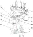
图1是本申请优选实施例的溶液自动分析装置的立体示意图。Fig. 1 is a schematic perspective view of an automatic solution analysis device in a preferred embodiment of the present application.
图2是本申请优选实施例的溶液自动分析装置另一视角的立体示意图。Fig. 2 is a schematic perspective view of another perspective of the automatic solution analysis device of the preferred embodiment of the present application.
图3是本申请优选实施例的溶液自动分析装置另一视角的立体示意图。Fig. 3 is a three-dimensional schematic view from another perspective of the automatic solution analysis device of the preferred embodiment of the present application.
图4是本申请优选实施例的样品处理装置立体示意图。Fig. 4 is a schematic perspective view of a sample processing device in a preferred embodiment of the present application.
图5是本申请优选实施例的样品处理装置另一视角的立体示意图。Fig. 5 is a schematic perspective view of another viewing angle of the sample processing device according to the preferred embodiment of the present application.
图6是本申请优选实施例的样品处理装置主视示意图。Fig. 6 is a schematic front view of a sample processing device in a preferred embodiment of the present application.
图7是本申请优选实施例的定容计量模组成示意图。Fig. 7 is a schematic diagram of a constant volume metering module in a preferred embodiment of the present application.
图8是本申请优选实施例的检测容器置换装置立体示意图。Fig. 8 is a schematic perspective view of a testing container replacement device according to a preferred embodiment of the present application.
图9是本申请优选实施例的检测容器置换装置另一角度立体示意图。Fig. 9 is a perspective view from another angle of the detection container replacement device of the preferred embodiment of the present application.
图10是本申请优选实施例的检测容器置换装置主视示意图。Fig. 10 is a schematic front view of a testing container replacement device in a preferred embodiment of the present application.
图11是本申请优选实施例的检测容器置换装置另一角度立体示意图(不含检测容器储存槽)。Fig. 11 is a perspective view from another angle of the detection container replacement device of the preferred embodiment of the present application (without the detection container storage tank).
图12是本申请优选实施例的检测容器置换装置另一角度立体示意图(局部)。Fig. 12 is a perspective view (partial) from another angle of the detection container replacement device of the preferred embodiment of the present application.
图13是本申请优选实施例的检测容器置换装置俯视示意图(局部)。Fig. 13 is a schematic top view (partial) of a testing container replacement device according to a preferred embodiment of the present application.
图14是本申请优选实施例的弹片装配示意图。Fig. 14 is a schematic diagram of the assembly of the shrapnel in the preferred embodiment of the present application.
图15是本申请优选实施例的分析检测装置立体示意图(局部)。Fig. 15 is a perspective view (partial) of an analysis and detection device in a preferred embodiment of the present application.
图中:1、底座;2、第一升降机构;3、第一旋转驱动机构;4、清洗位固定座;5、取样针清洗装置;6、清洗槽;7、检测模块清洗装置;8、检测模块安装座;9、检测模块;10、第二机械臂;11、第二转盘;12、检测容器;13、第一机械臂;14、滑道;15、第三机械臂;16、检测容器感应装置;17、抓取装置;18、检测容器供给装置;19、样品容器;20、减重孔;21、第一转盘;22、固定座;23、检测容器储存槽;24、直线导轨;25、顶出丝杆;26、顶出电机;27、第二旋转驱动机构;28、第二升降机构;29、第一升降电机;30、第一升降滑块;31、同步带;32、第一支架;33、第一旋转主动同步轮;34、第一旋转感应装置;35、第一旋转从动同步轮;36、取样针;37、检测电极;38、第一导杆;39、第一丝杆;40、第一旋转电机;41、第一旋转定位盘;42、第一升降主动同步轮;43、第一升降从动同步轮;44、第一液位传感器;45、第二液位传感器;46、气泵;47、第一电磁阀;48、压力检测装置;49、负压发生装置;50、第一液位指示;51、第二液位指示;52、样品液位;53、第二电磁阀;54、稀释泵;55、安装座;56、顶出滑块;57、存储槽盖;58、第三旋转感应装置;59、上极限装置;60、第三升降限位装置;61、第三旋转电机;62、第三支架;63、第三升降滑块;64、第三升降电机;65、第三丝杆;66、第三导杆;67、筒体下转接件;68、筒体上转接件;69、第三旋转从动同步轮;70、第三旋转主动同步轮;71、第三升降主动同步轮;72、第三升降从动同步轮;73、第三旋转定位盘;74、弹片;75、第一升降限位装置;76、第二旋转定位盘;77、第二旋转从动同步轮;78、第二导杆;79、第二升降滑块;80、第二升降从动同步轮;81、第二丝杆;82、第二支架;83、第二升降电机;84、第二升降限位装置;85、第二旋转电机;86、第二旋转主动同步轮;87、第二旋转感应装置;88、第三旋转驱动机构;89、第三升降机构。In the figure: 1. base; 2. first lifting mechanism; 3. first rotating drive mechanism; 4. cleaning position fixing seat; 5. sampling needle cleaning device; 6. cleaning tank; 7. detection module cleaning device; 8. Detection module mounting seat; 9. Detection module; 10. Second mechanical arm; 11. Second turntable; 12. Detection container; 13. First mechanical arm; 14. Slideway; 15. Third mechanical arm; 16. Detection Container induction device; 17. Grabbing device; 18. Detection container supply device; 19. Sample container; 20. Weight reduction hole; 21. First turntable; 25. Ejector screw rod; 26. Ejector motor; 27. The second rotary drive mechanism; 28. The second elevating mechanism; 29. The first elevating motor; 30. The first elevating slider; 31. Synchronous belt; 32 , the first bracket; 33, the first rotating active synchronous wheel; 34, the first rotating induction device; 35, the first rotating driven synchronous wheel; 36, the sampling needle; 37, the detection electrode; 38, the first guide rod; 39 , the first screw mandrel; 40, the first rotating motor; 41, the first rotary positioning plate; 42, the first lifting active synchronous wheel; 43, the first lifting driven synchronous wheel; 44, the first liquid level sensor; 45, Second liquid level sensor; 46. Air pump; 47. First solenoid valve; 48. Pressure detection device; 49. Negative pressure generating device; 50. First liquid level indication; 51. Second liquid level indication; 52. Sample liquid 53, the second solenoid valve; 54, the dilution pump; 55, the installation seat; 56, the ejection slider; 57, the storage tank cover; 58, the third rotation induction device; 59, the upper limit device; 60, the third Lifting limit device; 61, the third rotating motor; 62, the third bracket; 63, the third lifting slider; 64, the third lifting motor; 65, the third screw rod; 66, the third guide rod; 67, the tube Body lower adapter; 68, barrel upper adapter; 69, third rotating driven synchronous wheel; 70, third rotating active synchronizing wheel; 71, third lifting active synchronizing wheel; 72, third lifting driven Synchronous wheel; 73, the third rotating positioning disc; 74, shrapnel; 75, the first lifting limit device; 76, the second rotating positioning disc; 77, the second rotating driven synchronizing wheel; 78, the second guide rod; 79 , the second lift slider; 80, the second lift driven synchronous wheel; 81, the second screw rod; 82, the second support; 83, the second lift motor; 84, the second lift limit device; 85, the second Rotating motor; 86, the second rotating active synchronous wheel; 87, the second rotating induction device; 88, the third rotating driving mechanism; 89, the third lifting mechanism.
具体实施方式Detailed ways
需要说明的是,在不冲突的情况下,本申请中的实施例及实施例中的特征可以相互组合。下面将参考附图并结合实施例来详细说明本申请。It should be noted that, in the case of no conflict, the embodiments in the present application and the features in the embodiments can be combined with each other. The present application will be described in detail below with reference to the accompanying drawings and embodiments.
参照图1至图3所示,本申请的优选实施例提供了一种溶液自动分析装置,包括通过样品容器19提供样品溶液的样品供给装置、检测容器循环传送装置、样品处理装置、分析检测装置、检测容器置换装置,所述检测容器循环传送装置用于根据设定停歇周期将用于容纳所述样品溶液的检测容器12按设定顺序依次在样品处理装置、分析检测装置、检测容器置换装置之间循环传送;所述样品处理装置用于根据识别的样品信息对样品容器中的样品溶液进行相应处理和转移;所述分析检测装置设置在所述检测容器循环传送装置的一侧相应位置,用于对检测容器循环传送装置上的检测容器12中的样品溶液进行分析检测;所述检测容器置换装置设置在所述检测容器循环传送装置的一侧相应位置,用于向检测容器循环传送装置上放置新的检测容器12,以及在分析检测装置完成分析检测后,将完成检测的检测容器从所述检测容器循环传送装置上换下;在同一停歇周期内,所述样品处理装置、分析检测装置、检测容器置换装置完成相应作业。With reference to Fig. 1 to Fig. 3, the preferred embodiment of the present application provides a kind of solution automatic analysis device, comprises the sample supply device that provides sample solution through
本实施例提供了一种溶液自动分析装置,包括通过样品容器19提供样品溶液的样品供给装置、检测容器循环传送装置、样品处理装置、分析检测装置、检测容器置换装置,所述检测容器循环传送装置用于根据设定停歇周期将用于容纳所述样品溶液的检测容器按设定顺序依次在样品处理装置、分析检测装置、检测容器置换装置之间循环传送;所述样品处理装置用于根据识别的样品信息对样品容器中的样品溶液进行相应处理和转移;所述分析检测装置设置在所述检测容器循环传送装置的一侧相应位置,用于对检测容器循环传送装置上的检测容器12中的样品溶液进行分析检测;所述检测容器置换装置设置在所述检测容器循环传送装置的一侧相应位置,用于向检测容器循环传送装置上放置新的检测容器,以及在分析检测装置完成分析检测后,将完成检测的检测容器12从所述检测容器循环传送装置上换下;在同一停歇周期内,所述样品处理装置、分析检测装置、检测容器置换装置完成相应作业。本实施例的溶液自动分析装置大大提高了实验室检测的自动化水平,只需要操作员将样品倒入相应的样品容器19,即可根据样品信息自动对不同样品溶液进行相应的处理和分析,排除了人员操作分析对测试结果的影响因素,提高了检测的可靠性和自动化程度。本申请能够实现样品处理装置、分析检测装置、检测容器置换装置同时进行工作,减少化验人员数量,降低了人员成本,同时还能提高样品分析效率。此外,本实施例还可以根据样品处理装置、分析检测装置、检测容器置换装置的作业时间,合理配置检测容器的数量,减少无效等待时间,即通过融入精益生产的精髓,使整个检测过程的各个步骤顺畅无积压,从而最大限度的提高自动分析过程中的工作效率。本实施例出错率低,自动化程度高,当需要分析的样品量大时,可大幅降低工作强度和人力成本,提高检测效率。This embodiment provides an automatic solution analysis device, including a sample supply device for providing a sample solution through a
如图1至图3所示,在本申请的优选实施例中,所述样品供给装置包括第一转盘21,所述第一转盘21,间隙转动地设置在固定座22上,所述第一转盘21上设置有若干用于放置所述样品容器19的容器放置孔,另外,为减少重量,所述第一转盘21上还设置有减重孔20。As shown in FIGS. 1 to 3 , in a preferred embodiment of the present application, the sample supply device includes a
本实施例中,样品供给装置包括有第一转盘21,所示第一转盘21由电机驱动下间隙转动地设置在固定座22上,所述第一转盘21上设置有若干用于放置所述样品容器19的容器放置孔,检测前,操作人员将不同的样品溶液注入到相应的样品容器19内,第一转盘21带动各样品容器19按设定方向、速度、间隙周期转动,以便所述样品处理装置根据识别的样品信息对样品容器中的样品溶液进行相应处理和转移。为减轻第一转盘21的重量和用料成本,所述第一转盘21上还设置有若干减重孔20。本实施例采用转盘作为样品供给装置,通过第一转盘21的循环转动即可实现样品的可靠供给,该实施例结构简单、加工方便、成本低。In this embodiment, the sample supply device includes a
在本申请的优选实施例中,所述的样品供给装置包括间隙移动地设置在固定座22上的往复式直线传送带,所述往复式直线传送带上设置有若干用于放置所述样品容器19的容器放置孔。In a preferred embodiment of the present application, the sample supply device includes a reciprocating linear conveyor belt arranged on the fixed
本实施例中,样品供给装置包括有往复式直线传送带,所述往复式直线传送带由电机驱动下沿直线往复移动地设置在固定座22上,往复式直线传送带上沿直线方向设置有若干用于放置所述样品容器19的容器放置孔,检测前,操作人员将不同的样品溶液注入到相应的样品容器19内,往复式直线传送带带动各样品容器19按设定方向、速度、间隙周期直线移动,以便所述样品处理装置根据识别的样品信息对样品容器中的样品溶液进行相应处理和转移。该实施例结构简单、占地小、便于控制。In this embodiment, the sample supply device includes a reciprocating linear conveyor belt. The reciprocating linear conveyor belt is set on the fixed
在本申请的优选实施例中,所述的样品供给装置包括间隙转动地设置在固定座22上的循环式传送带,所述循环式传送带上设置有若干用于放置所述样品容器19的容器放置孔。In a preferred embodiment of the present application, the sample supply device includes an endless conveyor belt that is rotatably arranged on the fixed
本实施例中,样品供给装置包括有循环式传送带,所述循环式传送带由电机驱动下,沿环形路径循环移动地设置在固定座22上,循环式传送带上沿环形路径设置有若干用于放置所述样品容器19的容器放置孔,检测前,操作人员将不同的样品溶液注入到相应的样品容器19内,所述循环式传送带带动各样品容器19按环形路径、速度、间隙周期移动,以便所述样品处理装置根据识别的样品信息对样品容器中的样品溶液进行相应处理和转移。该实施例的循环式传送带购买和安装方便、标准化程度高、便于控制。In this embodiment, the sample supply device includes a circular conveyor belt, which is driven by a motor and set on the fixed
在本申请的优选实施例中,所述样品容器19设置有关联样品信息的标签/标识。针对不同的样品溶液,为了获得所需的检测结果,进行检测之前,往往需要先对其进行不同的处理,如有些样品溶液在检测前仅需进行定量抽取,有些样品溶液在检测前除了进行定量抽取外,还需要进行定量稀释,有些样品溶液在检测前除了需要行定量抽取外,还需要进行过滤处理,有些样品溶液在检测前除了需要进行定量抽取外,还需要添加添加剂,如添加絮凝剂进行絮凝沉降处理。有些样品溶液在检测前除了需要进行定量抽取外,还需要定量稀释、添加添加剂、过滤等至少两种以上的处理。具体采用何种处理方法,需要以样品信息为依据,为了便于所述样品处理装置根据识别的样品信息自动对样品溶液进行相应处理,本实施例在所述样品容器19设置有关联样品信息的标签/标识,通过读取所述样品容器19上设置的标签/标识,即可快速获得该样品容器19内的样品溶液的样品信息,如样品名、检测参数、样品参数、采样时间等,从而为后续的样品溶液的处理及分析策略提供必要的控制参数。In a preferred embodiment of the present application, the
在本申请的优选实施例中,所述样品标签/标识为RFID数字标签、二维码或一维码、样品容器19的位置信息、样品容器19的形状或颜色。In a preferred embodiment of the present application, the sample label/identification is an RFID digital label, a two-dimensional code or a one-dimensional code, the position information of the
本实施例中,关联样品信息的标签/标识可以多种多样,如RFID数字标签、二维码或一维码,还可以是样品容器19的位置信息、样品容器19的形状或颜色,通过实现约定不同的位置信息形状或颜色关联对应的样品信息,即可通过样品容器19的位置信息、样品容器19的形状或颜色快速识别出该样品容器19内的样品溶液的样品信息,如样品名、检测参数、样品参数、采样时间等,从而为后续的样品溶液样品处理及分析策略提供必要的控制参数,至于其他可以便于识别出该样品容器19内的样品溶液的样品信息的方式,本领域技术人员可以根据需要进行设定,方式不限,在此不再赘述。In this embodiment, the tags/identifications associated with sample information can be various, such as RFID digital tags, two-dimensional codes or one-dimensional codes, and can also be the position information of the
如图1至图3所示,在本申请的优选实施例中,所述检测容器循环传送装置包括第二转盘11,所述第二转盘11间隙转动地设置在固定座22上,所述第二转盘11上设置有与样品处理装置、分析检测装置、检测容器置换装置数量相匹配的多组检测容器放置孔,其中,每组检测容器放置孔的数量相一致。由于样品处理装置处理完每组样品的时间,需要与分析检测装置单次分析时间接近或相等才能最大化利用时间,让每组分析之间的间隙等待时间最小,因此,本实施例通过在检测容器循环传送装置上合理布置检测容器的位置和数量,提高了分析检测装置的分析效率;进一步地,所述第二转盘11上绕旋转中心相隔120度夹角地均匀设置有与样品处理装置、分析检测装置、检测容器置换装置的数量相匹配的三组检测容器放置孔,其中,每组检测容器放置孔的数量相一致,均为四个。另外,为减少自重,所述第二转盘11上还设置有减重孔20。As shown in Figures 1 to 3, in a preferred embodiment of the present application, the detection container circulation conveying device includes a
本实施例中,所述检测容器循环传送装置包括有第二转盘11,所述第二转盘11由电机驱动下间隙转动地设置在固定座22上,所述第二转盘11上绕旋转中心相隔120度夹角地均匀设置有与样品处理装置、分析检测装置、检测容器置换装置的数量相匹配的三组检测容器放置孔,其中,每组检测容器放置孔的数量相一致,均为四个,检测过程中,当第二转盘11处于一个停止周期内时,本实施例将完成以下三组作业:In this embodiment, the detection container circulation transmission device includes a
所述样品处理装置根据识别的样品信息对样品容器中的样品溶液进行相应处理和转移,实现第一组检测容器放置孔中的检测容器12中的样品溶液分析检测前的处理;所述分析检测装置则对位于第二组检测容器放置孔中的检测容器12中的样品溶液进行分析检测;同时,所述检测容器置换装置则向第三组检测容器放置孔中放置新的检测容器12,以及在分析检测装置完成分析检测后,将完成检测的检测容器从第三组检测容器放置孔中换下。本实施例中,每组检测容器放置孔的数量可根据需要进行调整,不限于四个,该数量可以由分析检测装置的检测时间决定,为了确保整个检测过程平衡,避免出现无效等待,在分析检测装置的检测时长一定的情况下,结合样品处理装置和检测容器置换装置的作业速度进行综合设置,其设置是:在分析检测装置进行检测的过程中,样品处理装置和检测容器置换装置将持续作业,当分析检测装置完成检测后,样品处理装置和检测容器置换装置也能够完成样品处理和检测容器置换作业,具体到本实施例中,分析检测装置完成四份样品溶液的检测时间、样品处理装置完成四份样品溶液处理的时间、检测容器置换装置完成四个检测容器置换的时间大致相同,从而保证样品溶液的检测、样品溶液的处理、检测容器的置换过程的平衡,避免出现无效等待,从而保证整个自动检测过程的高效性,实现检测过程的精益生产目标。另外,为减轻第二转盘11的自重和用料成本,所述第二转盘11上还设置有若干减重孔20。本实施例采用转盘进行检测容器循环传送,通过第二转盘11的循环转动即可实现检测容器的循环传送,结构简单、加工方便、成本低。The sample processing device performs corresponding processing and transfer on the sample solution in the sample container according to the identified sample information, so as to realize the processing before the analysis and detection of the sample solution in the
在本申请的优选实施例中,所述检测容器循环传送装置包括循环式传送带,所述循环式传送带间隙转动地设置在固定座22上,所述循环式传送带上设置有与样品处理装置、分析检测装置、检测容器置换装置数量相匹配的三组检测容器放置孔,其中,每组检测容器放置孔的数量相一致,均为四个。In a preferred embodiment of the present application, the detection container circulating conveying device includes a circulating conveyor belt, and the circulating conveyor belt is arranged on the fixed
与上述实施例不同的是,本实施例中检测容器循环传送装置采用的循环式传送带,即通过循环式传送带实现检测容器循环传送,该实施例的循环式传送带购买和安装方便、标准化程度高、便于控制。The difference from the above-mentioned embodiment is that in this embodiment, the circular conveyor belt used by the detection container circular transmission device, that is, the circular conveyor belt is used to realize the circular transmission of the detection container. The circular conveyor belt of this embodiment is convenient to purchase and install, and has a high degree of standardization. Easy to control.
如图4至图6所示,在本申请的优选实施例中,所述样品处理装置包括样品溶液转移装置、样品信息获取模块、溶液处理装置,所述样品溶液转移装置设置在底座1上,用于将样品溶液从样品供给装置的样品容器19中转移到检测容器循环传送装置的检测容器12中;所述样品信息获取模块用于对样品供给装置上关联有样品信息的样品标签/标识进行识别,获取样品信息;所述溶液处理装置与所述样品信息获取模块信号连接,用于根据识别的样品信息对样品容器19中的样品溶液进行相应处理。As shown in Figures 4 to 6, in a preferred embodiment of the present application, the sample processing device includes a sample solution transfer device, a sample information acquisition module, and a solution processing device, and the sample solution transfer device is arranged on the
本实施例的样品处理装置包括样品溶液转移装置、样品信息获取模块、溶液处理装置,所述样品溶液转移装置设置在底座1上,用于将样品溶液从样品供给装置的样品容器19中转移到检测容器循环传送装置的检测容器12中;所述样品信息获取模块用于对样品供给装置上关联有样品信息的样品标签/标识进行识别,获取样品信息,可以采用读码器、图形识别模块等;上述溶液处理装置与所述样品信息获取模块信号连接,用于根据识别的样品信息对样品容器19中的样品溶液进行相应处理。本实施例在检测过程中通过样品溶液转移装置进行样品溶液的转移,同时,可通过样品信息获取模块、溶液处理装置实现样品溶液的样品信息获取和相应处理,处理的具体类型由样品信息确定,包括定量提取、定量稀释、过滤等处理方法,整个过程无需人工进行操作,人为干预环节少,出错率低,自动化程度高,当需要分析的样品量大时,可大幅降低工作强度和人力成本,提高检测效率。The sample processing device of this embodiment includes a sample solution transfer device, a sample information acquisition module, and a solution processing device. The sample solution transfer device is arranged on the
如图1、4、5、6所示,在本申请的优选实施例中,所述样品溶液转移装置包括用于提供直线升降输出的第一升降机构2、用于提供周向旋转输出的第一旋转驱动机构3、第一机械臂13,所述第一机械臂13的后端与所述第一升降机构2和第一旋转驱动机构3驱动连接。As shown in Figures 1, 4, 5, and 6, in a preferred embodiment of the present application, the sample solution transfer device includes a
本实施例中,所述样品溶液转移装置包括第一升降机构2、第一旋转驱动机构3、第一机械臂13,所述第一机械臂13在第一升降机构2、第一旋转驱动机构3的作用可以完成上下升降和旋转动作,作业过程中可以根据需要控制第一机械臂13的升降高度和旋转角度,从而灵活可靠的实现对样品溶液的定量吸取和精确转移。In this embodiment, the sample solution transfer device includes a
具体的,所述第一升降机构2包括有第一支架32、第一导杆38、第一丝杆39、第一升降电机29、第一升降滑块30,所述第一支架32固定设置上述底座1上,所述第一导杆38竖直固定在所述第一支架32上,所述第一丝杆39与第一导杆38平行地转动设置在所述第一支架32上,所述第一升降电机29固定设置在所述第一支架32上,其输出轴通过传动机构与所述第一丝杆39驱动连接;所述传动机构包括分别设置在所述第一丝杆39端部和第一升降电机29输出轴上的第一升降从动同步轮43和第一升降主动同步轮42、连接设置在所述第一升降从动同步轮43和第一升降主动同步轮42之间的同步带31,所述传动机构采用带轮传动方式,结构简单、成本低、传动可靠、维护方便、噪声低,同时,作为替换手段,也可以采用其他传动方式,如齿轮传动、三角皮带传动、链轮传动等方式,本领域技术人员可以根据实际需要进行相应选择。升降过程中,第一升降电机29驱动第一丝杆39旋转,从而带动第一升降滑块30沿第一导杆38上下移动到达指定高度,由于第一升降滑块30同时还通过轴承与所述第一机械臂13的后端转动连接,因此,在第一升降滑块30沿第一导杆38上下移动的同时,将带动所述第一机械臂13上下移动,可精确将第一机械臂13升降至预定高度并可靠锁定,确保了第一机械臂13动作的精确性、稳定性和可靠性、自锁性。另外,所述第一升降机构2还包括第一升降限位装置75,设置在所述第一支架32上,用于限制所述第一升降滑块30的升降极限位置,当第一升降滑块30上升至极限位置时,第一升降限位装置75被触发发出相应信号,此时,相关控制系统根据该信号向第一升降电机29发送指令,使第一升降电机29停止转动,避免第一升降滑块30到位后使电机过载损坏。Specifically, the
所述第一旋转驱动机构3包括有第一旋转电机40、第一旋转从动同步轮35、第一旋转主动同步轮33,所述第一旋转电机40固定设置在所述第一支架32上且其输出轴连接第一旋转主动同步轮33,所述第一旋转从动同步轮35转动设置在所述第一支架32上,且与所述第一旋转主动同步轮33通过同步带31驱动连接,所述第一旋转从动同步轮35的中心设置有既能沿所述第一机械臂13后端轴向滑动,又能驱动第一机械臂13后端旋转的旋转驱动孔,所述旋转驱动孔为多边形孔或花键孔,此时所述第一机械臂13既可在第一升降滑块30的驱动下上下升降,又能在第一旋转主动同步轮33和同步带31驱动第一旋转从动同步轮35转动时,通过所述旋转驱动孔带动所述第一机械臂13同步转动,使升降和转动动作既可依次进行,亦可同时进行,确保第一机械臂13的高效移动,提高作业效率。另外,所述旋转驱动机构还包括旋转限位装置,该旋转限位装置包括第一旋转定位盘41和第一旋转感应装置34,所述第一旋转定位盘41固定设置在所述第一旋转从动同步轮35上,第一旋转感应装置34设置在所述第一支架32上,用于感应所述第一旋转定位盘41的旋转位置,第一旋转定位盘41上沿周向间隔设置有若干镂空孔,所述第一旋转感应装置34可采用霍尔传感器等,当第一旋转定位盘41转动使镂空孔正对第一旋转感应装置34时,所述第一旋转感应装置34发出信号,相应的控制系统则控制第一旋转电机40停止转动,使第一机械臂13停留在当前旋转位置,从而准确限定第一机械臂13的旋转位置,避免第一机械臂13在作业过程中位置不准,同时还可以防止第一机械臂13旋转到位时造成电机过载。The first
在本申请的优选实施例中,所述溶液处理装置包括定容计量模组,所述定容计量模组设置在所述样品溶液转移装置上,用于按设定容量对样品容器19中的样品溶液进行抽取并注入到位于检测容器循环传送装置上的检测容器12中。In a preferred embodiment of the present application, the solution processing device includes a constant volume metering module, and the constant volume metering module is arranged on the sample solution transfer device for distributing the sample solution in the
具体地,如图7所示,所述定容计量模组包括取样针36、液位计量装置、负压发生装置49,所述取样针36设置在所述样品溶液转移装置上,所述负压发生装置49通过管路依次连接液位计量装置和取样针36,所述液位计量装置包括第一液位传感器44和第二液位传感器45,分别提供第一液位指示50、第二液位指示51来实现对两种固定液位的计量检测,确保定量抽取样品溶液。作为优选实施例,所述定容计量模组还包括压力检测装置48,所述压力检测装置48设置在负压发生装置49和所述液位计量装置之间的管路上,用于检测取样针36插入样品溶液的深度,确保取样针在能够吸取到足量样品溶液的前提下,尽可能少的接触样品溶液,便于取样针的清洗。Specifically, as shown in Figure 7, the constant volume metering module includes a
上述实施例中,所述溶液处理装置包括定容计量模组,该定容计量模组的主要用于按设定容量对样品容器19中的样品溶液进行抽取并注入到位于检测容器循环传送装置上的检测容器12中,当根据识别的样品信息判断出分析前需要对样品溶液进行定量抽取时,所述第一机械臂13在第一升降机构2和第一旋转驱动机构3驱动下到达样品供给装置上的相应样品容器19所在位置时,第一机械臂13带动取样针36下降至指定高度后,负压发生装置49启动,使取样针36从样品容器19中抽取样品溶液,当抽取的样品溶液达到预定量时,各液位传感器给出信号,负压发生装置49停止作业,同时,第一机械臂13在第一升降机构2和第一旋转驱动机构3驱动下到达检测容器循环传送装置上相应检测容器12所在位置,接着,所述负压发生装置49启动,将定量吸取的样品溶液注入到相应的检测容器12内等待下一步进行分析。In the above embodiment, the solution processing device includes a constant volume metering module, which is mainly used to extract the sample solution in the
作为优选实施例,所述定容计量模组还包括气泵46,所述气泵46通过液位计量装置与取样针36连接,通过气泵46通入空气,当需要排出液位计量装置和取样针36内液体时,可将液位计量装置和取样针36内的液体吹出;而当清洗液位计量装置和取样针36时,可以加速清洗液的排出,提高清洗效率。优选地,所述气泵46通过第一电磁阀47与液位计量装置、取样针36连接。As a preferred embodiment, the constant volume metering module also includes an
如图7所示,在本申请的优选实施例中,所述溶液处理装置还包括溶液稀释装置,所述溶液稀释装置包括稀释泵54,所述稀释泵28用于根据样品信息对样品溶液进行设定倍数的稀释。优选地,所述稀释泵54通过第二电磁阀53与所述液位计量装置和取样针36相连接。As shown in Figure 7, in a preferred embodiment of the present application, the solution processing device also includes a solution dilution device, and the solution dilution device includes a
本实施例中,所述溶液处理装置还包括溶液稀释装置,该溶液稀释装置包括稀释泵54,用于根据样品信息对样品溶液进行设定倍数的稀释。在获取样品信息确定还需要对该样品溶液进行定量稀释处理时,先完成样品溶液的定量抽取,稀释泵54开启,抽取定量的稀释液对样品溶液进行设定倍数的稀释。优选地,稀释泵54通过液位计量装置与取样针36连接,在抽取稀释液对样品溶液进行稀释时,稀释液经过液位计量装置和取样针36,可以对液位计量装置和取样针36进行冲洗,减少样品溶液在液位计量装置和取样针中的残留,提高稀释精度,从而确保检测结果的准确性。In this embodiment, the solution processing device further includes a solution diluting device, and the solution diluting device includes a
如图7所示,在本申请的优选实施例中,所述溶液稀释装置还包括:As shown in Figure 7, in a preferred embodiment of the present application, the solution dilution device also includes:
检测电极37,所述检测电极37设置在所述样品溶液转移装置上,如设置在第一机械臂13前端且与所述取样针36竖直平行,用于开启稀释泵54对溶液进行定量稀释或添加时定容至检测电极37下端位置。A
本实施例中,作为一种稀释液的定量措施,所述溶液稀释装置还包括检测电极37,在获取了样品信息后,系统将控制第一机械臂13带动检测电极37到达检测容器12上方指定高度,所述指定高度与检测容器12中样品溶液稀释时所需的稀释液的用量相关联,在启动稀释泵54和第二电磁阀53向相应的检测容器12内注入一定的稀释液的过程中,若检测容器12内的样品液位52达到所述检测电极37的下端位置时,所述检测电极37发送信号,相应的控制系统根据该信号发出指令,关闭稀释泵54,检测电极37结构简单,控制可靠,从而根据样品信息实现样品溶液的不同稀释倍数的精准稀释。In this embodiment, as a quantitative measure of the diluent, the solution diluting device also includes a
除此之外,还可以选择仅利用稀释泵54根据样品信息取相应量的稀释液进行定量稀释,利用检测电极37对稀释后的量(溶液体积)进行检测,提高定量稀释的准确性,避免由于稀释泵54长期使用老化带来的定量误差。In addition, you can also choose to use the
在本申请的优选实施例中,所述溶液处理装置还包括过滤装置,用于将样品溶液从样品供给装置的样品容器19中转移到检测容器循环传送装置上的检测容器12之前,对所述样品溶液进行过滤处理。In a preferred embodiment of the present application, the solution processing device also includes a filter device, which is used to transfer the sample solution from the
本实施例中,所述溶液处理装置还包括有过滤装置,用于对所述样品溶液进行过滤处理,当根据识别的样品信息判断出分析前还需要对样品溶液进行过滤处理时,系统控制第一机械臂13带动取样针36先将样品溶液从样品供给装置的样品容器19中抽取并转移到过滤装置中进行过滤,以滤除其中的相关物质,接着,所述第一机械臂13再将过滤后的样品溶液定量抽取后转移到检测容器循环传送装置上的检测容器12内,若还需要稀释处理,则进一步进行稀释作业,具体过程与前述定量抽取和稀释过程相类似,在此不再在赘述。In this embodiment, the solution processing device further includes a filter device for filtering the sample solution. When it is judged that the sample solution needs to be filtered before analysis according to the identified sample information, the system controls the first A
在本申请的优选实施例中,所述样品处理装置还包括:In a preferred embodiment of the present application, the sample processing device further includes:
取样针清洗装置5,设置在清洗位固定座4上,用于对所述取样针36进行清洗,包括水洗、酸洗或碱洗,所述取样针清洗装置5包括清洗杯,所述清洗杯上设置有排废口、加液口,用于实现蒸馏水、酸液或碱液的自动加液、自动排废。The sampling
如图1所示,本实施例中,所述样品处理装置还包括有取样针清洗装置5,主要实现对取样针36进行清洗,如水洗、酸洗或碱洗等,避免后续作业时对样品溶液造成污染而影响分析结果的准确性和可靠性,取样针清洗装置5可实现自动加液、排废,无需人工操作,大幅减少人工的劳动强度和对人员的健康危害。As shown in Figure 1, in this embodiment, the sample processing device also includes a sampling
如图3所示,在本申请的优选实施例中,所述分析检测装置包括用于提供直线升降输出的第二升降机构28、用于提供周向旋转输出的第二旋转驱动机构27、第二机械臂10、若干检测模块9,所述第二机械臂10的后端与所述第二升降机构28和第二旋转驱动机构27驱动连接;所述检测模块9通过检测模块安装座8设置在所述第二机械臂10的前端,用于对检测容器12内的样品进行分析检测。As shown in Figure 3, in a preferred embodiment of the present application, the analysis and detection device includes a
本实施例中,所述分析检测装置包括第二升降机构28、第二旋转驱动机构27、第二机械臂10、若干检测模块9,所述第二机械臂10在第二升降机构28、第二旋转驱动机构27的作用可以完成上下升降和旋转动作,作业过程中可以根据需要控制第二机械臂10的升降高度和旋转角度,从而灵活可靠的控制各检测模块9移动至指定位置,并下降至指定高度后对各检测容器12内的样品溶液进行分析检测。In this embodiment, the analysis and detection device includes a
具体地,如图15所示,所述第二升降机构28包括第二支架82、第二导杆78、第二丝杆81、第二升降电机83、第二升降滑块79、第二升降限位装置84、传动机构,所述传动机构包括分别设置在所述第二丝杆81端部和第二升降电机83输出轴上的第二升降从动同步轮80和第二升降主动同步轮、连接设置在所述第二升降从动同步轮80和第二升降主动同步轮之间的同步带31。本实施例中第二升降机构28的各组成部件的连接关系和工作原理与所述第一升降机构2的各组成部件的连接关系和工作原理相类似,在此不再赘述。Specifically, as shown in Figure 15, the
所述第二旋转驱动机构27包括有第二旋转电机85、第二旋转从动同步轮77、第二旋转主动同步轮86、同步带31、旋转限位装置,所述旋转限位装置包括第二旋转定位盘76和第二旋转感应装置87,本实施例中所述第二旋转驱动机构27的各组成部件的连接关系和工作原理与所述第一旋转驱动机构3的各组成部件的连接关系和工作原理类似,在此不再赘述。The second
如图1所示,在本申请的优选实施例中,所述分析检测装置还包括:As shown in Figure 1, in a preferred embodiment of the present application, the analysis and detection device also includes:
检测模块清洗装置7,固定在清洗位固定座4上,用于对各个检测模块9进行清洗,包括水洗、酸洗或碱洗。所述检测模块清洗装置7包括清洗槽6,所述清洗槽设置有排废口、加液口,用于实现蒸馏水、酸液或碱液的自动加液、自动排废。进一步地,所述清洗槽6设置有若干清洗位。The detection
本实施例中,所述分析检测装置还包括检测模块清洗装置7,主要实现对各个检测模块9进行清洗,如水洗、酸洗或碱洗等,避免后续作业时对样品溶液造成污染而影响分析结果的准确性和可靠性,检测模块清洗装置7的每个清洗位可实现自动加液、排废,无需人工操作,大幅减少人工的劳动强度和对人员的健康危害。In this embodiment, the analysis and detection device also includes a detection
如图1、图2所示,在本申请的优选实施例中,所述检测容器置换装置包括检测容器供给装置18、废检测容器收集装置、检测容器抓送装置,所述检测容器供给装置18设置在底座1上,用于存储和提供新的检测容器12;所述废检测容器收集装置用于收集完成检测的检测容器12;所述检测容器抓送装置设置在所述底座1上,用于从检测容器供给装置18上抓取新的检测容器12移送至检测容器循环传送装置上,以及从检测容器循环传送装置上抓取完成检测的检测容器12移送至所述废检测容器收集装置。As shown in Fig. 1 and Fig. 2, in a preferred embodiment of the present application, the detection container replacement device includes a detection
本实施例的检测容器置换装置包括检测容器供给装置18、废检测容器收集装置、检测容器抓送装置,所述检测容器供给装置18设置在底座1上,用于存储和提供检测容器12;所述废检测容器收集装置用于收集完成检测的检测容器12;所述检测容器抓送装置设置在所述底座1上,用于从检测容器供给装置18上抓取新的检测容器12移送至检测容器循环传送装置上,以及从检测容器循环传送装置上抓取完成检测的检测容器12移送至废检测容器收集装置。本实施例提供的检测容器置换装置在检测过程中通过检测容器供给装置18提供检测容器12,同时,通过检测容器抓送装置实现检测容器12的丢弃和置换,丢弃和置换过程无需人工进行操作,人为干预环节少,出错率低,当需要分析的样品量大时,可大幅降低工作强度和人力成本,提高检测效率。The detection container replacement device of this embodiment includes a detection
如图2所示,在本申请的优选实施例中,所述检测容器抓送装置包括第三升降机构89、第三旋转驱动机构88、第三机械臂15,所述第三升降机构89固定在底座1上,用于提供直线升降输出;所述第三旋转驱动机构88固定在所述第三升降机构89上,用于提供周向旋转输出;所述第三机械臂15的后端与所述第三升降机构89和第三旋转驱动机构88驱动连接,前端设置有用于抓取检测容器12的抓取装置17。As shown in Figure 2, in a preferred embodiment of the present application, the detection container grabbing device includes a
本实施例中,根据检测容器12丢弃和更换的需要,所述检测容器抓送装置包括有第三升降机构89、第三旋转驱动机构88和第三机械臂15,所述第三机械臂15的后端与所述第三升降机构89、第三旋转驱动机构88驱动连接,其中,第三升降机构89能够驱动第三机械臂15上下升降,从而调整第三机械臂15前端的抓取装置17至合适的高度,而第三旋转驱动机构88则可以驱动第三机械臂15旋转角度,第三升降机构89、第三旋转驱动机构88相配合,可以调整第三机械臂15前端的抓取装置17达到需要抓取的检测容器12所在的位置和高度,从而使抓取装置17能够精确的抓取新的检测容器12或者将完成检测的检测容器12移送至废检测容器收集装置,当然,作为一种变形,亦可将第三旋转驱动机构88固定设置在所述底座1上,接着将第三升降机构89固定在第三旋转驱动机构88输出端,同样可以驱动第三机械臂15进行升降和旋转。In this embodiment, according to the needs of discarding and replacing the
具体地,如图8至图13所示,所述第三升降机构89包括第三支架62、第三导杆66、第三丝杆65、第三升降电机64、第三升降滑块63、第三升降限位装置60、传动机构,所述传动机构包括分别设置在所述第三丝杆65端部和第三升降电机64输出轴上的第三升降从动同步轮72和第三升降主动同步轮71、连接设置在所述第三升降从动同步轮72和第三升降主动同步轮71之间的同步带31。本实施例中第三升降机构89的各组成部件的连接关系和工作原理与所述第一升降机构2的各组成部件的连接关系和工作原理相类似,在此不再赘述。Specifically, as shown in FIGS. 8 to 13, the
所述第三旋转驱动机构88包括有第三旋转电机61、第三旋转从动同步轮69、第三旋转主动同步轮70、同步带31、旋转限位装置,所述旋转限位装置包括第三旋转定位盘73和第三旋转感应装置58,本实施例中所述第三旋转驱动机构88的各组成部件的连接关系和工作原理与所述第一旋转驱动机构3的各组成部件的连接关系和工作原理相类似,在此不再赘述。The third
如图8和图10所示,在本申请的优选实施例中,所述检测容器抓送装置还包括检测容器感应装置16,所述检测容器感应装置16设置在所述第三机械臂15前端,用于抓取装置17在检测容器循环传送装置或检测容器供给装置18上抓取前检测是否存在检测容器12,若存在,则驱动抓取装置17实施相应的抓取动作。As shown in FIGS. 8 and 10 , in a preferred embodiment of the present application, the detection container grabbing device further includes a detection
本实施例中,所述第三机械臂15前端还设置有检测容器感应装置16,该检测容器感应装置16可在抓取装置17在检测容器循环传送装置或检测容器供给装置18上抓取前检测是否存在检测容器12,即:在检测检测容器循环传送装置时,若检测容器感应装置16检测到所述检测检测容器循环传送装置不存在检测容器12,则所述抓取装置17的控制系统将不会向所述抓取装置17发送任何控制指令或者根据实际需求情况发出警示信息,避免抓取装置17做无效的抓取工作。在检测检测容器供给装置18时,若检测容器感应装置16检测到检测容器供给装置18不存在检测容器12,则所述抓取装置17的控制系统将不会向所述抓取装置17发送任何控制指令或者发出警示信息,避免所述抓取装置17做无效的抓取工作,以提醒人员需要向检测容器供给装置18及时补充检测容器12。In this embodiment, the front end of the third
在本申请的优选实施例中,所述的检测容器供给装置18包括检测容器储存槽23、顶出机构,所述检测容器储存槽23固定设置在所述底座1上,用于存储检测容器12,所述检测容器储存槽23的出口设置有存储槽盖57,如图14所示,所述存储槽盖57的内侧设置有若干用于分离各检测容器12的弹片74;所述顶出机构固定设置在所述底座1上,用于将检测容器12从检测容器储存槽23内向上依次顶出。In a preferred embodiment of the present application, the detection
本实施例中,所述检测容器供给装置18包括有检测容器储存槽23和顶出机构,所述检测容器储存槽23包括存储有多个新的检测容器12的筒体,筒体的上端设置有筒体上转接件68,下端设置有筒体下转接件67,筒体上转接件68通过安装座55固定在底座1上,所述顶出机构则根据需要,将检测容器12从检测容器储存槽23内向上依次顶出,所述弹片74可防止抓取装置17抓取最上层的检测容器12时,下一个检测容器12受摩擦力影响被同时上提,确保检测容器储存槽23内的检测容器12能够被一个一个依次抓取,避免一次抓取多个检测容器12。顶出后,控制第三机械臂15至检测容器供给装置18所在位置,同时第三机械臂15前端的抓取装置17将顶出的新的检测容器12一一抓取并移送至检测容器循环传送装置上,本实施例中,第三机械臂15在每个作业周期中每完成四个检测容器12的抓取,当四个检测容器12被抓取后,即完成检测容器的更换。In this embodiment, the detection
在本申请的优选实施例中,所述顶出机构包括直线导轨24、驱动机构、顶出滑块56,所述顶出滑块56在所述驱动机构的带动下在所述直线导轨24上滑动,引导所述顶出滑块56上移将检测容器12从检测容器储存槽23内向上依次顶出。In a preferred embodiment of the present application, the ejection mechanism includes a
本实施例中,所述顶出机构包括直线导轨24、驱动机构、顶出滑块56,所述驱动机构驱动顶出滑块56沿直线导轨24滑动,即可实现将检测容器12从检测容器储存槽23内向上依次顶出。In this embodiment, the ejection mechanism includes a
作为优选实施例,所述驱动机构包括:顶出丝杆25和顶出电机26,所述顶出电机26的输出轴与所述顶出丝杆25驱动连接,所述顶出丝杆25与所述顶出滑块56配合,驱动所述顶出丝杆25在直线导轨24上直线运动,将检测容器12从检测容器储存槽23内向上依次顶出。As a preferred embodiment, the drive mechanism includes: an
本实施例中,所述顶出机构包括直线导轨24、顶出丝杆25、顶出滑块56、顶出电机26,顶出作业时,顶出电机26驱动顶出丝杆25转动,继而驱动顶出滑块56沿直线导轨24上移,所述顶出滑块56则在上移的过程中将将检测容器12从检测容器储存槽23内向上依次顶出,顶出电机26采用周期性转动的方式,即在一个检测容器12被顶出后即停止转动,待第三机械臂15带动抓取装置17抓取该检测容器12后,所述顶出电机26再次转动,将下一个检测容器12顶出,以此类推,直到检测容器循环传送装置上的相应位置全部按需放置好检测容器12,需要指出的是,除了本实施例中的顶出丝杆25和顶出电机26相配合驱动顶出滑块56沿直线导轨24上移外,还可以选择其他驱动机构驱动顶出滑块56滑动,如液压缸、气压缸、皮带拉动、直线电机等,在此不再一一赘述,本领域技术人员可根据需要相应选择。In this embodiment, the ejection mechanism includes a
作为优选实施例,所述顶出机构还包括上极限装置59和下限位装置,用于限制所述顶出滑块56上、下移动的极限位置,当顶出滑块56在驱动机构的驱动下在直线导轨24上滑动至上极限位置时,上极限装置59被触发发出相应信号,此时,相关控制系统将向驱动机构发送指令,使驱动机构停止驱动顶出滑块56继续向上滑动,避免顶出滑块56到位后,驱动机构继续驱动顶出滑块56在直线导轨上向上滑动导致驱动机构过载损坏。同时,发出检测容器储存槽24内需添加检测容器12的预警。向检测容器储存槽24内添加检测容器12之前,需对顶出滑块56进行复位,即控制驱动机构驱动顶出滑块56在直线导轨上向下滑动至下限位位置,下极限装置被触发发出相应信号,此时,相关控制系统将向驱动机构发送指令,使驱动机构停止驱动顶出滑块56继续向下滑动,避免顶出滑块56到位后,驱动机构继续驱动顶出滑块56在直线导轨上向下滑动导致驱动机构过载损坏。As a preferred embodiment, the ejection mechanism also includes an
在本申请的优选实施例中,所述废检测容器收集装置包括有贯穿固定在底座1上的滑道14,用于将完成检测的检测容器12输送至预定位置集中处理。本实施例中,所述废检测容器收集装置包括有贯穿固定在底座1上的滑道14,当完成检测的检测容器12需要丢弃时,控制所述第三机械臂15前端的抓取装置17将完成检测的检测容器12抓取并移送至滑道14入口,完成检测的检测容器12将掉入滑道14内并沿着滑道14输送至预定位置集中处理,本实施例中之所以设置滑道14,是因为完成检测的检测容器12内依然存放有作废的检测溶液,为了防止检测容器12在丢弃过程中检测容器12中检测溶液污染环境或溅出,因此,本实施例采用滑道14,确保检测溶液在丢弃过程中能够完全自动被收集到预定位置进行处理,安全、环保。为了进一步对检测容器12在滑道14输送过程的速度进行缓冲,所述滑道14采用弯形管状滑道14,避免检测容器12中检测溶液在重力作用下溅出。In a preferred embodiment of the present application, the waste testing container collection device includes a
现场样品送达实验室后,分析人员将样品溶液加入样品供给装置对应的样品容器19中,当样品容器19转到样品信息读取模块位置时,样品处理装置根据识别的样品信息对样品容器中的样品溶液进行相应处理和转移,接着,所述分析检测装置对检测容器循环传送装置上的检测容器12中的样品溶液进行分析检测,最后,所述检测容器置换装置设置在所述检测容器循环传送装置的一侧相应位置,用于向检测容器循环传送装置上放置新的检测容器12,以及在分析检测装置完成分析检测后,将完成检测的检测容器从所述检测容器循环传送装置上换下,在检测容器循环传送装置的同一停歇周期内,所述样品处理装置、分析检测装置、检测容器置换装置自动完成相应作业,在经过多次停歇周期和相关装置的协同作业后,即可自动完成对样品供给装置上所有样品溶液的自动分析。After the on-site sample is delivered to the laboratory, the analyst adds the sample solution into the
以上所述仅为本申请的优选实施例而已,并不用于限制本申请,凡在本申请的精神和原则之内,所作的任何修改、等同替换、改进等,均应包含在本申请的保护范围之内。The above is only a preferred embodiment of the application, and is not intended to limit the application. Any modifications, equivalent replacements, improvements, etc. made within the spirit and principles of the application shall be included in the protection of the application. within range.
Claims (15)
Priority Applications (1)
| Application Number | Priority Date | Filing Date | Title |
|---|---|---|---|
| CN202111658834.8ACN116413460A (en) | 2021-12-31 | 2021-12-31 | Automatic solution analysis device |
Applications Claiming Priority (1)
| Application Number | Priority Date | Filing Date | Title |
|---|---|---|---|
| CN202111658834.8ACN116413460A (en) | 2021-12-31 | 2021-12-31 | Automatic solution analysis device |
Publications (1)
| Publication Number | Publication Date |
|---|---|
| CN116413460Atrue CN116413460A (en) | 2023-07-11 |
Family
ID=87051629
Family Applications (1)
| Application Number | Title | Priority Date | Filing Date |
|---|---|---|---|
| CN202111658834.8APendingCN116413460A (en) | 2021-12-31 | 2021-12-31 | Automatic solution analysis device |
Country Status (1)
| Country | Link |
|---|---|
| CN (1) | CN116413460A (en) |
Cited By (2)
| Publication number | Priority date | Publication date | Assignee | Title |
|---|---|---|---|---|
| CN116413468A (en)* | 2021-12-31 | 2023-07-11 | 力合科技(湖南)股份有限公司 | Control method of automatic analysis device for sodium aluminate solution |
| CN120057405A (en)* | 2025-04-30 | 2025-05-30 | 复崟(上海)科技有限公司 | Sample refrigeration storage device and sample access method |
Citations (15)
| Publication number | Priority date | Publication date | Assignee | Title |
|---|---|---|---|---|
| US5380487A (en)* | 1992-05-05 | 1995-01-10 | Pasteur Sanofi Diagnostics | Device for automatic chemical analysis |
| US20090148345A1 (en)* | 2007-12-07 | 2009-06-11 | Hamazumi Yuko | Automated analyzer |
| CN102326087A (en)* | 2009-02-20 | 2012-01-18 | 株式会社日立高新技术 | Automatic analysis device |
| JP2012021862A (en)* | 2010-07-14 | 2012-02-02 | Hitachi High-Technologies Corp | Automatic analyzer |
| CN102762988A (en)* | 2010-01-28 | 2012-10-31 | 株式会社日立高新技术 | Automatic analyzing device |
| CN102985830A (en)* | 2010-07-09 | 2013-03-20 | 株式会社日立高新技术 | Automatic analyzer |
| CN106596989A (en)* | 2017-02-05 | 2017-04-26 | 深圳市活水床旁诊断仪器有限公司 | Full-automatic immunization analyzer and detection method |
| CN106770913A (en)* | 2016-12-09 | 2017-05-31 | 中储粮成都粮食储藏科学研究所 | A kind of fatty acid value automatic tester |
| CN106885915A (en)* | 2017-03-16 | 2017-06-23 | 江苏柯伦迪医疗技术有限公司 | A kind of New Blood analyzer and method |
| CN106896049A (en)* | 2017-03-16 | 2017-06-27 | 江苏柯伦迪医疗技术有限公司 | A kind of multi-parameter blood analyser and method |
| CN206362758U (en)* | 2016-12-09 | 2017-07-28 | 中储粮成都粮食储藏科学研究所 | One kind titration detection circulating work platform |
| CN107271707A (en)* | 2017-08-03 | 2017-10-20 | 力合科技(湖南)股份有限公司 | The sampling device of a kind of sampler and the use device, detecting system |
| CN109142766A (en)* | 2018-09-28 | 2019-01-04 | 基蛋生物科技股份有限公司 | Chemiluminescence detector |
| CN110007101A (en)* | 2019-04-09 | 2019-07-12 | 安邦(厦门)生物科技有限公司 | Detection device and detection method |
| CN214252321U (en)* | 2020-12-31 | 2021-09-21 | 深圳市新产业生物医学工程股份有限公司 | Sample analyzer |
- 2021
- 2021-12-31CNCN202111658834.8Apatent/CN116413460A/enactivePending
Patent Citations (15)
| Publication number | Priority date | Publication date | Assignee | Title |
|---|---|---|---|---|
| US5380487A (en)* | 1992-05-05 | 1995-01-10 | Pasteur Sanofi Diagnostics | Device for automatic chemical analysis |
| US20090148345A1 (en)* | 2007-12-07 | 2009-06-11 | Hamazumi Yuko | Automated analyzer |
| CN102326087A (en)* | 2009-02-20 | 2012-01-18 | 株式会社日立高新技术 | Automatic analysis device |
| CN102762988A (en)* | 2010-01-28 | 2012-10-31 | 株式会社日立高新技术 | Automatic analyzing device |
| CN102985830A (en)* | 2010-07-09 | 2013-03-20 | 株式会社日立高新技术 | Automatic analyzer |
| JP2012021862A (en)* | 2010-07-14 | 2012-02-02 | Hitachi High-Technologies Corp | Automatic analyzer |
| CN206362758U (en)* | 2016-12-09 | 2017-07-28 | 中储粮成都粮食储藏科学研究所 | One kind titration detection circulating work platform |
| CN106770913A (en)* | 2016-12-09 | 2017-05-31 | 中储粮成都粮食储藏科学研究所 | A kind of fatty acid value automatic tester |
| CN106596989A (en)* | 2017-02-05 | 2017-04-26 | 深圳市活水床旁诊断仪器有限公司 | Full-automatic immunization analyzer and detection method |
| CN106896049A (en)* | 2017-03-16 | 2017-06-27 | 江苏柯伦迪医疗技术有限公司 | A kind of multi-parameter blood analyser and method |
| CN106885915A (en)* | 2017-03-16 | 2017-06-23 | 江苏柯伦迪医疗技术有限公司 | A kind of New Blood analyzer and method |
| CN107271707A (en)* | 2017-08-03 | 2017-10-20 | 力合科技(湖南)股份有限公司 | The sampling device of a kind of sampler and the use device, detecting system |
| CN109142766A (en)* | 2018-09-28 | 2019-01-04 | 基蛋生物科技股份有限公司 | Chemiluminescence detector |
| CN110007101A (en)* | 2019-04-09 | 2019-07-12 | 安邦(厦门)生物科技有限公司 | Detection device and detection method |
| CN214252321U (en)* | 2020-12-31 | 2021-09-21 | 深圳市新产业生物医学工程股份有限公司 | Sample analyzer |
Cited By (2)
| Publication number | Priority date | Publication date | Assignee | Title |
|---|---|---|---|---|
| CN116413468A (en)* | 2021-12-31 | 2023-07-11 | 力合科技(湖南)股份有限公司 | Control method of automatic analysis device for sodium aluminate solution |
| CN120057405A (en)* | 2025-04-30 | 2025-05-30 | 复崟(上海)科技有限公司 | Sample refrigeration storage device and sample access method |
Similar Documents
| Publication | Publication Date | Title |
|---|---|---|
| CN212111456U (en) | Full-automatic urine analysis system | |
| EP2409159B1 (en) | Aliquoting apparatus for biological material containers | |
| EP2908952B1 (en) | Condensation-reducing sample tube array system | |
| US9260763B2 (en) | Sample processing method using tube strips and tube strip holder | |
| CN116413460A (en) | Automatic solution analysis device | |
| US9135515B2 (en) | Automated pelletized sample vision inspection apparatus and methods | |
| US9873921B2 (en) | Ultrasonic biological sample analysis apparatus and methods | |
| US9435718B2 (en) | Automated pelletized sample decanting apparatus and methods | |
| US20140112829A1 (en) | Tube strip handling and heating apparatus | |
| EP3308129A1 (en) | A machinery for an automated analysis of the slides in accordance with the indirect immunofluorescence assay - ifa | |
| CN110369319B (en) | Automatic information acquisition and sorting device and method for test sample containers | |
| CN116413468A (en) | Control method of automatic analysis device for sodium aluminate solution | |
| CN111235031A (en) | Smart semen optimization system | |
| CN116413077A (en) | Automatic extraction and treatment device for sample solution | |
| CN115216394B (en) | Fully automatic nucleic acid sample pretreatment system | |
| CN115999193A (en) | Multi-station continuous full-automatic liquid-liquid extraction device based on AI visual liquid level monitoring and use method | |
| JP7286154B2 (en) | Specimen Dilution Device, Specimen Aggregation Device, and Specimen Dilution Method | |
| JP7376905B2 (en) | dilution device | |
| CN219434469U (en) | Sample post-processing system | |
| US20250258070A1 (en) | Liquid processing system and related methods | |
| CN117007827B (en) | Water quality detection system | |
| US9310281B2 (en) | Automated pelletized sample blotting apparatus and methods | |
| CN208155959U (en) | A kind of liquid quantitative transfer device of fatty acid value detector | |
| CN120652116A (en) | Detection device for biological fluid sample | |
| CN117031054A (en) | Pretreatment device and sample detection instrument |
Legal Events
| Date | Code | Title | Description |
|---|---|---|---|
| PB01 | Publication | ||
| PB01 | Publication | ||
| SE01 | Entry into force of request for substantive examination | ||
| SE01 | Entry into force of request for substantive examination | ||
| RJ01 | Rejection of invention patent application after publication | ||
| RJ01 | Rejection of invention patent application after publication | Application publication date:20230711 |