CN116412199A - Hinge mechanism and mobile terminal - Google Patents
Hinge mechanism and mobile terminalDownload PDFInfo
- Publication number
- CN116412199A CN116412199ACN202111651862.7ACN202111651862ACN116412199ACN 116412199 ACN116412199 ACN 116412199ACN 202111651862 ACN202111651862 ACN 202111651862ACN 116412199 ACN116412199 ACN 116412199A
- Authority
- CN
- China
- Prior art keywords
- plate
- assembly
- gear
- rotating
- hinge mechanism
- Prior art date
- Legal status (The legal status is an assumption and is not a legal conclusion. Google has not performed a legal analysis and makes no representation as to the accuracy of the status listed.)
- Pending
Links
Images


Classifications
- F—MECHANICAL ENGINEERING; LIGHTING; HEATING; WEAPONS; BLASTING
- F16—ENGINEERING ELEMENTS AND UNITS; GENERAL MEASURES FOR PRODUCING AND MAINTAINING EFFECTIVE FUNCTIONING OF MACHINES OR INSTALLATIONS; THERMAL INSULATION IN GENERAL
- F16C—SHAFTS; FLEXIBLE SHAFTS; ELEMENTS OR CRANKSHAFT MECHANISMS; ROTARY BODIES OTHER THAN GEARING ELEMENTS; BEARINGS
- F16C11/00—Pivots; Pivotal connections
- F16C11/04—Pivotal connections
- G—PHYSICS
- G09—EDUCATION; CRYPTOGRAPHY; DISPLAY; ADVERTISING; SEALS
- G09F—DISPLAYING; ADVERTISING; SIGNS; LABELS OR NAME-PLATES; SEALS
- G09F9/00—Indicating arrangements for variable information in which the information is built-up on a support by selection or combination of individual elements
- G09F9/30—Indicating arrangements for variable information in which the information is built-up on a support by selection or combination of individual elements in which the desired character or characters are formed by combining individual elements
- G09F9/301—Indicating arrangements for variable information in which the information is built-up on a support by selection or combination of individual elements in which the desired character or characters are formed by combining individual elements flexible foldable or roll-able electronic displays, e.g. thin LCD, OLED
- H—ELECTRICITY
- H04—ELECTRIC COMMUNICATION TECHNIQUE
- H04M—TELEPHONIC COMMUNICATION
- H04M1/00—Substation equipment, e.g. for use by subscribers
- H04M1/02—Constructional features of telephone sets
- H04M1/0202—Portable telephone sets, e.g. cordless phones, mobile phones or bar type handsets
- H04M1/0206—Portable telephones comprising a plurality of mechanically joined movable body parts, e.g. hinged housings
- H04M1/0208—Portable telephones comprising a plurality of mechanically joined movable body parts, e.g. hinged housings characterized by the relative motions of the body parts
- H04M1/0214—Foldable telephones, i.e. with body parts pivoting to an open position around an axis parallel to the plane they define in closed position
- H04M1/0216—Foldable in one direction, i.e. using a one degree of freedom hinge
- H04M1/022—The hinge comprising two parallel pivoting axes
- H—ELECTRICITY
- H05—ELECTRIC TECHNIQUES NOT OTHERWISE PROVIDED FOR
- H05K—PRINTED CIRCUITS; CASINGS OR CONSTRUCTIONAL DETAILS OF ELECTRIC APPARATUS; MANUFACTURE OF ASSEMBLAGES OF ELECTRICAL COMPONENTS
- H05K5/00—Casings, cabinets or drawers for electric apparatus
- H05K5/02—Details
- H05K5/0217—Mechanical details of casings
- H05K5/0226—Hinges
Landscapes
- Engineering & Computer Science (AREA)
- General Engineering & Computer Science (AREA)
- Mechanical Engineering (AREA)
- Microelectronics & Electronic Packaging (AREA)
- Signal Processing (AREA)
- Physics & Mathematics (AREA)
- General Physics & Mathematics (AREA)
- Theoretical Computer Science (AREA)
- Telephone Set Structure (AREA)
Abstract
Translated fromChinese
Description
Translated fromChinese技术领域technical field
本发明涉及柔性屏移动终端技术领域,尤其涉及一种铰链机构及移动终端。The invention relates to the technical field of flexible screen mobile terminals, in particular to a hinge mechanism and a mobile terminal.
背景技术Background technique
由于电子产品技术的提高,柔性屏、可折叠屏的应用日趋增加。现有技术中,为了实现移动终端屏幕可折叠,一般将移动终端分为第一外壳组件和第二外壳组件,第一外壳组件和第二外壳组件通过铰链机构连接,从而第一外壳组件和第二外壳组件能够折叠,同时柔性屏进行折叠。Due to the improvement of electronic product technology, the application of flexible screens and foldable screens is increasing day by day. In the prior art, in order to realize the folding of the screen of the mobile terminal, the mobile terminal is generally divided into a first shell component and a second shell component, and the first shell component and the second shell component are connected by a hinge mechanism, so that the first shell component and the second shell The second shell assembly can be folded, and the flexible screen is folded simultaneously.
但现有的铰链机构,在整机的运动过程中,会对柔性屏形成挤压力,从而导致柔性屏使用寿命的减少,且由于零件细化,导致铰链机构零件多,导致组装误差大且成本高。However, the existing hinge mechanism will form a squeezing force on the flexible screen during the movement of the whole machine, resulting in a reduction in the service life of the flexible screen, and due to the refinement of parts, there are many parts in the hinge mechanism, resulting in large assembly errors and high cost.
为解决上述问题,亟待提供一种铰链机构及移动终端。In order to solve the above problems, it is urgent to provide a hinge mechanism and a mobile terminal.
发明内容Contents of the invention
本发明的一个目的是提出一种铰链机构,以达到简化结构、降低成本且提高柔性屏使用寿命的效果。An object of the present invention is to provide a hinge mechanism to achieve the effects of simplifying the structure, reducing the cost and improving the service life of the flexible screen.
本发明的另一个目的是提出一种移动终端,通过上述铰链机构,以达到简化结构、降低成本且提高柔性屏使用寿命的效果。Another object of the present invention is to provide a mobile terminal, through the above-mentioned hinge mechanism, to achieve the effects of simplifying the structure, reducing the cost and improving the service life of the flexible screen.
为达此目的,本发明采用以下技术方案:For reaching this purpose, the present invention adopts following technical scheme:
一种铰链机构,被配置为连接第一外壳组件和第二外壳组件,所述铰链机构包括:A hinge mechanism configured to connect a first housing assembly and a second housing assembly, the hinge mechanism comprising:
两组转板组件,其中一组所述转板组件的一端与所述第一外壳组件连接,另一组所述转板组件的一端与所述第二外壳组件连接,所述转板组件包括转动板和转轴板,所述转轴板的一端与所述转动板可转动连接;以及Two sets of rotating plate assemblies, wherein one end of the rotating plate assembly in one group is connected to the first shell assembly, and one end of the other group of rotating plate assemblies is connected to the second shell assembly, and the rotating plate assembly includes a rotating plate and a rotating shaft plate, one end of the rotating shaft plate is rotatably connected to the rotating plate; and
齿轮组件,所述齿轮组件与所述转轴板背离所述转动板的一端啮合。A gear assembly, the gear assembly meshes with an end of the rotating shaft plate away from the rotating plate.
作为一种可选方案,所述转轴板包括:As an optional solution, the shaft plate includes:
转轴板本体;Shaft plate body;
连接销,设置在所述转轴板本体上,所述转动板上开设有第一滑槽,所述连接销能够穿过所述第一滑槽,使所述转轴板本体与所述转动板可转动连接;以及The connecting pin is arranged on the main body of the rotating shaft plate, and a first slide groove is opened on the rotating plate, and the connecting pin can pass through the first sliding groove, so that the rotating shaft plate body and the rotating plate can swivel connection; and
第一齿轮,设置在所述转轴板本体上,且所述第一齿轮与所述齿轮组件啮合。The first gear is arranged on the shaft plate body, and the first gear is engaged with the gear assembly.
作为一种可选方案,所述齿轮组件包括固定底座,所述固定底座上开设有连接槽,所述转动板包括:As an optional solution, the gear assembly includes a fixed base, and a connecting groove is opened on the fixed base, and the rotating plate includes:
转动板本体;rotating plate body;
连接部,与所述转动板本体连接,且所述连接部设置在所述连接槽中,且所述连接部能够在所述连接槽中转动。The connecting part is connected with the rotating plate body, and the connecting part is arranged in the connecting groove, and the connecting part can rotate in the connecting groove.
作为一种可选方案,所述转板组件还包括:As an optional solution, the rotating plate assembly also includes:
连接板,所述连接板与所述第一外壳组件或所述第二外壳组件连接,且所述转动板上设置有旋转轴,所述连接板的局部与所述旋转轴可转动连接。A connecting plate, the connecting plate is connected to the first shell component or the second shell component, and a rotating shaft is arranged on the rotating plate, and a part of the connecting plate is rotatably connected to the rotating shaft.
作为一种可选方案,所述转板组件还包括:As an optional solution, the rotating plate assembly also includes:
连接板,所述连接板上开设有第二滑槽,所述连接销设置在所述第二滑槽中,使所述转轴板本体与所述连接板可转动连接。The connecting plate is provided with a second sliding groove, and the connecting pin is arranged in the second sliding groove so that the rotating shaft plate body is rotatably connected to the connecting plate.
作为一种可选方案,所述齿轮组件还包括:As an optional solution, the gear assembly also includes:
支撑底座;以及support base; and
齿轮组,所述齿轮组的两端分别与两个所述转轴板啮合;a gear set, the two ends of the gear set mesh with the two shaft plates respectively;
多个齿轮轴,多个所述齿轮轴分别穿过所述齿轮组以及两个所述转轴板,所述支撑底座为两个,所述齿轮轴的两端分别与设置在两端的所述支撑底座可转动连接。A plurality of gear shafts, a plurality of the gear shafts pass through the gear set and the two rotating shaft plates respectively, there are two support bases, and the two ends of the gear shaft are respectively connected to the support set at the two ends The base is rotatably connected.
作为一种可选方案,所述齿轮组件还包括:As an optional solution, the gear assembly also includes:
移动凸轮,所述移动凸轮套设在所述齿轮轴上;a moving cam, the moving cam is sleeved on the gear shaft;
固定凸轮,套设在所述齿轮轴上,且所述固定凸轮设置在所述齿轮组背离所述支撑底座的一侧,所述固定凸轮与所述齿轮组以及两个所述转动板连接,所述固定凸轮能够驱动所述移动凸轮沿所述齿轮轴的轴线方向移动;以及The fixed cam is sleeved on the gear shaft, and the fixed cam is arranged on the side of the gear set away from the support base, the fixed cam is connected with the gear set and the two rotating plates, The fixed cam can drive the moving cam to move along the axial direction of the gear shaft; and
多个复位件,套设在所述齿轮轴上,且所述复位件设置在所述支撑底座和所述移动凸轮之间。A plurality of reset members are sleeved on the gear shaft, and the reset members are arranged between the support base and the moving cam.
作为一种可选方案,所述固定凸轮上开设有多个凹陷部,所述凹陷部设置在背离所述齿轮组的一端,且所述凹陷部沿所述固定凸轮周向间隔设置,所述移动凸轮包括凸轮本体和多个凸轮部,所述凸轮本体套设在所述齿轮轴上,且所述凸轮部沿所述凸轮本体向远离所述凸轮本体的方向延伸,多个所述凸轮部与多个所述凹陷部一一配合设置。As an optional solution, the fixed cam is provided with a plurality of recesses, the recesses are arranged at an end away from the gear set, and the recesses are arranged at intervals along the circumference of the fixed cam, the The moving cam includes a cam body and a plurality of cam parts, the cam body is sleeved on the gear shaft, and the cam part extends away from the cam body along the cam body, and the plurality of cam parts It is arranged in cooperation with a plurality of said recessed parts one by one.
作为一种可选方案,所述铰链机构还包括:As an optional solution, the hinge mechanism also includes:
中心板,覆盖在所述齿轮组件上,所述第一外壳组件和所述第二外壳组件沿相互靠近的方向折叠时,两个所述转动板与所述中心板围设形成等腰三角形。The central plate covers the gear assembly. When the first shell assembly and the second shell assembly are folded toward each other, the two rotating plates and the central plate form an isosceles triangle.
一种移动终端,包括:A mobile terminal, comprising:
第一外壳组件和第二外壳组件;以及a first housing assembly and a second housing assembly; and
如上所述的铰链机构,所述铰链机构的两端分别与所述第一外壳组件和所述第二外壳组件连接。As for the above hinge mechanism, both ends of the hinge mechanism are respectively connected to the first shell component and the second shell component.
本发明的有益效果为:The beneficial effects of the present invention are:
本发明提供一种用于连接第一外壳组件和第二外壳组件的铰链机构。该铰链机构包括齿轮组件和两组转板组件。其中一组转板组件的一端与第一外壳组件连接,另一组转板组件的一端与第二外壳组件连接,转板组件包括转动板和转轴板,转轴板的一端与转动板可转动连接,齿轮组件与转轴板背离转动板的一端啮合,使转轴板既起到连接的作用,又起到与齿轮组件啮合,驱动齿轮组件运动,集成多个结构效果,有效降低组装误差和加工成本。在齿轮组件与转板组件的作用下,能够实现移动终端的同步联动转动,以减小可折叠的移动终端在转动过程中对柔性屏体的挤压力,降低柔性面板受损风险,从而提高柔性面板及移动终端的使用寿命,进而能够满足不同用户对铰链机构区域贴屏平整性的要求。The present invention provides a hinge mechanism for connecting a first housing assembly and a second housing assembly. The hinge mechanism includes a gear assembly and two sets of rotating plate assemblies. One end of one set of rotating plate assemblies is connected to the first shell assembly, and one end of the other set of rotating plate assemblies is connected to the second shell assembly. The rotating plate assembly includes a rotating plate and a rotating shaft plate, and one end of the rotating shaft plate is rotatably connected to the rotating plate. , the gear assembly meshes with the end of the rotating shaft plate away from the rotating plate, so that the rotating shaft plate not only plays the role of connection, but also plays a role in meshing with the gear assembly, driving the gear assembly to move, integrating multiple structural effects, and effectively reducing assembly errors and processing costs. Under the action of the gear assembly and the rotating plate assembly, the synchronous linkage rotation of the mobile terminal can be realized, so as to reduce the extrusion force of the foldable mobile terminal on the flexible screen during the rotation process, reduce the risk of damage to the flexible panel, and improve The service life of the flexible panel and the mobile terminal can meet the requirements of different users for the flatness of the screen in the hinge mechanism area.
本发明还提供一种移动终端,通过上述铰链机构,简化移动终端结构,实现降低成本,且提高了柔性屏的使用寿命,进而有利于提高移动终端的使用寿命。The present invention also provides a mobile terminal. Through the hinge mechanism, the structure of the mobile terminal is simplified, the cost is reduced, and the service life of the flexible screen is improved, which is beneficial to improve the service life of the mobile terminal.
附图说明Description of drawings
为了更清楚地说明本发明实施例中的技术方案,下面将对本发明实施例描述中所需要使用的附图作简单的介绍,显而易见地,下面描述中的附图仅仅是本发明的一些实施例,对于本领域普通技术人员来讲,在不付出创造性劳动的前提下,还可以根据本发明实施例的内容和这些附图获得其他的附图。In order to more clearly illustrate the technical solutions in the embodiments of the present invention, the following will briefly introduce the accompanying drawings that need to be used in the description of the embodiments of the present invention. Obviously, the accompanying drawings in the following description are only some embodiments of the present invention , for those skilled in the art, other drawings can also be obtained according to the content of the embodiment of the present invention and these drawings without any creative effort.
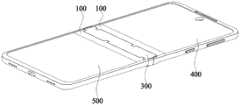
图1是本发明实施例提供的移动终端展平状态的结构示意图;FIG. 1 is a schematic structural diagram of a mobile terminal in a flattened state provided by an embodiment of the present invention;
图2是本发明实施例提供的移动终端折叠状态的结构示意图;FIG. 2 is a schematic structural diagram of a folded state of a mobile terminal provided by an embodiment of the present invention;
图3是本发明实施例提供的移动终端的结构示意图;FIG. 3 is a schematic structural diagram of a mobile terminal provided by an embodiment of the present invention;
图4是本发明实施例提供的铰链机构的结构示意图一;Fig. 4 is a structural schematic diagram 1 of the hinge mechanism provided by the embodiment of the present invention;
图5是本发明实施例提供的铰链机构的结构示意图二;Fig. 5 is the second structural schematic diagram of the hinge mechanism provided by the embodiment of the present invention;
图6是图5中A-A处的剖面图;Fig. 6 is the sectional view of A-A place among Fig. 5;
图7是图5中B-B处的剖面图;Fig. 7 is the sectional view of B-B place among Fig. 5;
图8是本发明实施例提供的转轴板和齿轮组件的结构示意图;Fig. 8 is a schematic structural view of a rotating shaft plate and a gear assembly provided by an embodiment of the present invention;
图9是本发明实施例提供的转板组件的结构示意图;Fig. 9 is a schematic structural diagram of a rotating plate assembly provided by an embodiment of the present invention;
图10是图9中C处的局部放大图;Fig. 10 is a partial enlarged view of place C in Fig. 9;
图11是本发明实施例提供的铰链机构展平状态的结构示意图;Fig. 11 is a schematic structural view of the hinge mechanism in a flattened state provided by an embodiment of the present invention;
图12是图5中D处的局部放大图;Fig. 12 is a partial enlarged view at D in Fig. 5;
图13是本发明实施例提供的铰链机构折叠状态的剖面结构示意图。Fig. 13 is a schematic cross-sectional structural view of the folded state of the hinge mechanism provided by the embodiment of the present invention.
图中标记如下:The markings in the figure are as follows:
100-转板组件;110-转动板;111-转动板本体;112-连接部;1121-安装槽;113-旋转轴;114-第一滑槽;120-转轴板;121-转轴板本体;122-连接销;123-第一齿轮;130-连接板;131-第二滑槽;140-转动连接块;100-rotation plate assembly; 110-rotation plate; 111-rotation plate body; 112-connection; 1121-installation groove; 113-rotation shaft; 114-first chute; 122-connecting pin; 123-the first gear; 130-connecting plate; 131-the second chute; 140-rotate the connecting block;
200-齿轮组件;210-固定底座;211-连接槽;220-支撑底座;230-齿轮组;231-第二齿轮;240-齿轮轴;250-移动凸轮;251-凸轮本体;252-凸轮部;260-固定凸轮;261-凹陷部;270-复位件;200-gear assembly; 210-fixed base; 211-connecting groove; 220-support base; 230-gear set; 231-second gear; 240-gear shaft; 250-moving cam; 251-cam body; 252-cam part ; 260-fixed cam; 261-sag; 270-resetting part;
300-中心板;300-center plate;
400-第一外壳组件;400 - first housing assembly;
500-第二外壳组件;500 - second housing assembly;
600-铰链外壳;600 - hinged housing;
700-柔性屏。700 - Flexible screen.
具体实施方式Detailed ways
下面结合附图和实施例对本发明作进一步的详细说明。可以理解的是,此处所描述的具体实施例仅仅用于解释本发明,而非对本发明的限定。另外还需要说明的是,为了便于描述,附图中仅示出了与本发明相关的结构分而非全结构。The present invention will be further described in detail below in conjunction with the accompanying drawings and embodiments. It should be understood that the specific embodiments described here are only used to explain the present invention, but not to limit the present invention. In addition, it should be noted that, for the convenience of description, only parts of the structures related to the present invention are shown in the drawings but not the whole structures.
在本发明的描述中,除非另有明确的规定和限定,术语“相连”、“连接”、“固定”应做广义理解,例如,可以是固定连接,也可以是可拆卸连接,或成一体;可以是机械连接,也可以是电连接;可以是直接相连,也可以通过中间媒介间接相连,可以是两个元件内结构的连通或两个元件的相互作用关系。对于本领域的普通技术人员而言,可以具体情况理解上述术语在本发明中的具体含义。In the description of the present invention, unless otherwise clearly specified and limited, the terms "connected", "connected" and "fixed" should be understood in a broad sense, for example, it can be a fixed connection, a detachable connection, or an integrated ; It can be a mechanical connection or an electrical connection; it can be a direct connection or an indirect connection through an intermediary, and it can be the communication of the internal structure of two components or the interaction relationship between two components. Those of ordinary skill in the art can understand the specific meanings of the above terms in the present invention in specific situations.
在本发明中,除非另有明确的规定和限定,第一特征在第二特征之“上”或之“下”可以包括第一和第二特征直接接触,也可以包括第一和第二特征不是直接接触而是通过它们之间的另外的特征接触。而且,第一特征在第二特征“之上”、“上方”和“上面”包括第一特征在第二特征正上方和斜上方,或仅仅表示第一特征水平高度高于第二特征。第一特征在第二特征“之下”、“下方”和“下面”包括第一特征在第二特征正下方和斜下方,或仅仅表示第一特征水平高度小于第二特征。In the present invention, unless otherwise clearly specified and limited, a first feature being "on" or "under" a second feature may include direct contact between the first and second features, and may also include the first and second features Not in direct contact but through another characteristic contact between them. Moreover, "above", "above" and "above" the first feature on the second feature include that the first feature is directly above and obliquely above the second feature, or simply means that the first feature is horizontally higher than the second feature. "Below", "beneath" and "under" the first feature to the second feature include that the first feature is directly below and obliquely below the second feature, or simply means that the first feature has a lower level than the second feature.
在本实施例的描述中,术语“上”、“下”、“左”、“右”等方位或位置关系为基于附图所示的方位或位置关系,仅是为了便于描述和简化操作,而不是指示或暗示所指的装置或元件必须具有特定的方位、以特定的方位构造和操作,因此不能理解为对本发明的限制。此外,术语“第一”、“第二”仅仅用于在描述上加以区分,并没有特殊的含义。In the description of this embodiment, the terms "up", "down", "left", "right" and other orientations or positional relationships are based on the orientations or positional relationships shown in the drawings, and are only for the convenience of description and simplification of operations. It is not intended to indicate or imply that the referred device or element must have a particular orientation, be constructed in a particular orientation, and operate in a particular orientation, and thus should not be construed as limiting the invention. In addition, the terms "first" and "second" are only used to distinguish in description, and have no special meaning.
如图1~图3所示,本实施例提供一种移动终端,该移动终端包括铰链机构、第一外壳组件400和第二外壳组件500,铰链机构用于连接第一外壳组件400和第二外壳组件500,以使第一外壳组件400和第二外壳组件500连接形成一体结构。As shown in Figures 1 to 3, this embodiment provides a mobile terminal, the mobile terminal includes a hinge mechanism, a
如图1~图3所示,具体而言,第一外壳组件400主要包括第一外壳上盖、第一外壳中盖、第一外壳下盖,以上共同形成了可以容纳电子功能组件的密闭空间。第二外壳组件500主要包括第二外壳上盖、第二外壳中盖、第二外壳下盖,以上共同形成了可以容纳电子功能组件的密闭空间。可以理解的是,第一外壳组件400或者第二外壳组件500还包括电源键、音量键、按键支架。As shown in Figures 1 to 3, specifically, the
进一步地,该移动终端还包括柔性屏700,该柔性屏700贴附于第一外壳上盖与第二外壳上盖的凹槽内,以便于固定。该移动终端通过设置柔性屏700有利于减小移动终端的外形尺寸,能够满足不同用户的需求。Further, the mobile terminal further includes a
现结合图4~图13对铰链机构的细节结构进行说明。The detailed structure of the hinge mechanism will now be described with reference to FIGS. 4 to 13 .
如图4~图6所示,铰链机构包括齿轮组件200和两组转板组件100。其中一组转板组件100的一端与第一外壳组件400连接,另一组转板组件100的一端与第二外壳组件500连接,转板组件100包括转动板110和转轴板120,转轴板120的一端与转动板110可转动连接,齿轮组件200与转轴板120背离转动板110的一端啮合,使转轴板120既起到连接的作用,又起到与齿轮组件200啮合,驱动齿轮组件200运动,集成多个结构效果,有效降低组装误差和加工成本。在齿轮组件200与转板组件100的作用下,能够实现移动终端的同步联动转动,以减小可折叠的移动终端在转动过程中对柔性屏700体的挤压力,降低柔性面板受损风险,从而提高柔性面板及移动终端的使用寿命,进而能够满足不同用户对铰链机构区域贴屏平整性的要求。As shown in FIGS. 4 to 6 , the hinge mechanism includes a
可以理解的是,两组转板组件100对称设置在齿轮组件200的两侧。为了提高转动组件与齿轮组件200连接的稳定性,每组转动组件包括两个转轴板120,两个转轴板120沿转动组件延伸方向间隔设置。It can be understood that the two sets of
通过该铰链机构,该移动终端结构简单,成本大幅降低,且提高了柔性屏700的使用寿命,进而有利于提高移动终端的使用寿命。Through the hinge mechanism, the mobile terminal has a simple structure, greatly reduces the cost, and improves the service life of the
如图6所示,铰链机构还包括中心板300,中心板300覆盖在齿轮组件200上,当第一外壳组件400和第二外壳组件500处于展平状态时,中心板300与移动终端的其他结构共面设置,起到密封作用,防止齿轮组件200进水或进尘。第一外壳组件400和第二外壳组件500沿相互靠近的方向折叠时,两个转动板110与中心板300围设形成等腰三角形,在齿轮组件200与转板组件100的作用下,能够实现移动终端的同步联动转动,以减小可折叠的移动终端在转动过程中对柔性屏700体的挤压力,减少柔性面板受损概率,从而提高柔性面板及移动终端的使用寿命,进而能够满足不同用户对铰链机构区域贴屏平整性的要求。示例性地,折叠后,两个转动板110夹角为16°,该角度较小,既能够实现第一外壳组件400和第二外壳组件500的折叠,又能够减少对柔性屏700幕的挤压。As shown in FIG. 6, the hinge mechanism further includes a
请继续参见图6,该铰链机构还包括铰链外壳600,铰链外壳600的圆弧外观面在移动终端展平的时候隐藏在第一外壳组件400和第二外壳组件500里面,在移动终端折叠的时候外露出移动终端,作为移动终端外观的一部分。Please continue to refer to FIG. 6, the hinge mechanism also includes a
请继续参见图6,作为一种可选方案,转轴板120包括转轴板本体121、连接销122以及第一齿轮123。其中,连接销122设置在转轴板本体121上,转动板110上开设有第一滑槽114,连接销122能够穿过第一滑槽114,使转轴板本体121与转动板110可转动连接,第一齿轮123设置在转轴板本体121上,且第一齿轮123与齿轮组件200啮合。转轴板120位于齿轮组件200和转动板110之间,转轴板120的第一齿轮123与齿轮组件200啮合,可以完全隐藏在铰链机构内,不需要在移动终端正面外观面上加宽边框遮盖面积,从而可以将移动终端的边框做得很窄,目前可以将移动终端侧边的外观宽度做到1.5mm左右。Please continue to refer to FIG. 6 , as an optional solution, the
请继续参见图6,通过连接销122在第一滑槽114内滑动,实现转动板110转动过程中能够使转轴板120与转动板110连接相对固定,连接销122在第一滑槽114中滑动,能够为转动轴转动提供导向,以保证转动板110和转轴板120连接的稳定性。同时,第一齿轮123与齿轮组件200啮合,以便于将转动板110的转动动力通过转轴板120向齿轮组件200传递,实现铰链机构稳定转动。可以理解的是,转动板110上开设有两个第一滑槽111,两个转轴板120分别与两个第一滑动槽对应设置,从而在转动板110的延伸方向上设置两个转轴板120,当移动终端宽度增加时,两个转轴板120同时连接于转动板110和齿轮组件200之间,有利于保证转动板110在长度方向上运动的一致性,避免第一外壳组件400和第二外壳组件500相对转动时对于柔性屏700产生扭矩,有利于提高柔性屏700的使用寿命。Please continue to refer to FIG. 6 , through the connecting
如图7和图8所示,进一步地,齿轮组件200包括固定底座210,固定底座210上开设有连接槽211,转动板110包括转动板本体111和连接部112,连接部112与转动板本体111连接,且连接部112设置在连接槽211中,且连接部112能够在连接槽211中转动,连接槽211既能够对连接部112转动过程提供导向,且有利于提高转动板110转动的稳定性,且实现将转动板110与齿轮组件200连接,提高铰链机构的稳定性。固定底座210主要起到支撑、固定作用。As shown in Fig. 7 and Fig. 8, further, the
如图9和图10所示,进一步地,连接部112为弧形结构,连接部112的弧形中心形成与连接槽211同轴的凹槽,转板组件100还包括转动连接块140,转动连接块140设置在该凹槽中,以便于将连接部112固定在固定底座210上。As shown in Figure 9 and Figure 10, further, the connecting
请继续参见图9和图10,转板组件100还包括连接板130,连接板130与第一外壳组件400和第二外壳组件500连接,且转动板110上设置有旋转轴113,连接板130的局部与旋转轴113可转动连接,通过连接板130实现与第一外壳组件400或第二外壳组件500连接,实现第一外壳组件400和第二外壳组件500的运动驱动力向转板组件100以及齿轮组件200传递。具体而言,在齿轮组件200的一侧,连接板130平行于转动板110设置,转动板110的两端分别设置有一个旋转轴113,连接板130的两端分别设置有搭接部,两个搭接部分别搭设在两个旋转轴113上,并能够相对旋转轴113转动,进而实现连接板130能够相对转动板110转动,以便于调整转动板110和连接板130的相对角度。同时,在转动板110和连接板130两端设置连接结构,有利于保证在连接板130的长度方向上连接稳定,且连接板130和转动板110相对运动稳定。Please continue to refer to FIG. 9 and FIG. 10 , the
请继续参见图9和图10,进一步地,连接板130上开设有第二滑槽131,连接销122设置在第二滑槽131中,使转轴板本体121与连接板130可转动连接,即连接销122同时与第二滑槽131和第一滑槽114中滑动,以控制转动板110在第一外壳组件400和第二外壳组件500折叠至折叠时候的角度,且便于保证铰链机构的联动作用,提高铰链机构运动的稳定性。Please continue to refer to FIG. 9 and FIG. 10 , further, the connecting
由此可见,第一外壳组件400和第二外壳组件500主要的连接关系依靠相对设置的两个转轴板120实现,设置的两个转轴板120一端的第一齿轮123分别与两个固定凸轮260连接,另一端的连接销122第一滑槽114和第二滑槽131连接,实现第一外壳组件400和第二外壳组件500展平与折叠动作的连接与传递。It can be seen that the main connection relationship between the
如图11所示,当移动终端处于展平状态时,转轴板120的连接销122位于第一滑槽114与第二滑槽131靠近第一外壳组件400或第二外壳组件500的一端,第一滑槽114与第二滑槽131成10°的夹角。当用户给予第一外壳组件400或第二外壳组件500转动力时,移动终端第一外壳组件400和第二外壳组件500分别围绕齿轮组件200的第一齿轮123的中心旋转,转轴板120的连接销122分别在第一滑槽114与第二滑槽131里做直线运动,转动板110与连接板130围绕旋转轴113的中心做旋转运动,转板组件100绕连接槽211的中心做旋转运动。当移动终端处于折叠状态时,转轴板120的连接销122位于第一滑槽114与第二滑槽131中靠近齿轮组件200的一端,第一滑槽114与第二滑槽131成2°的夹角,两个转动板110形成约16°的等腰三角形空间,柔性屏700也形成了16°的水滴状形状,避免对柔性屏700造成挤压。As shown in FIG. 11 , when the mobile terminal is in the flattened state, the connecting
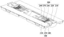
如图5和图8和图12所示,齿轮组件200还包括支撑底座220、齿轮组230以及多个齿轮轴240,齿轮组230的两端分别与两个转轴板120啮合,即对称设置在齿轮组件200两侧的两个转轴板120的两个第一齿轮123啮合,多个齿轮轴240分别穿过齿轮组230以及两个转轴板120,支撑底座220为两个,齿轮轴240的两端分别与设置在两端的支撑底座220可转动连接,以便于转动板110转动时带动转轴板120转动,进而通过转轴板120的第一齿轮123驱动齿轮组230转动。且支撑底座220具有支撑和固定作用。进一步地,齿轮组230包括两个平行且相互啮合设置的第二齿轮231,齿轮轴240包括四个,四个齿轮轴240分别穿过两个第一齿轮123和两个第二齿轮231设置。5, 8 and 12, the
如图5和图8和图12所示,齿轮组件200还包括固定凸轮260、移动凸轮250以及多个复位件270。其中,移动凸轮250套设在四个齿轮轴240,移动凸轮250能够在四个齿轮轴240上沿齿轮轴240的轴线方向移动,但不能转动。固定凸轮260套设在齿轮轴240上,且固定凸轮260设置在齿轮组230背离支撑底座220的一侧,固定凸轮260与齿轮组230以及两个转动板110连接,固定凸轮260能够驱动移动凸轮250沿齿轮轴240的轴线方向移动,复位件270套设在齿轮轴240上,且复位件270设置在支撑底座220和移动凸轮250之间,移动凸轮250、齿轮轴240、复位件270主要起阻尼作用,实现第一外壳组件400和第二外壳组件500折叠过程中能够在任意位置停留。具体而言,复位件270优选为弹簧,弹簧属于常规零件,便于采购,且使用寿命长,成本低。可以理解的是,复位件270为四个,与齿轮轴240的数量对应设置。As shown in FIG. 5 , FIG. 8 and FIG. 12 , the
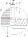
如图12所示,固定凸轮260上开设有多个凹陷部261,凹陷部261设置在背离齿轮组230的一端,且凹陷部261沿固定凸轮260周向间隔设置,移动凸轮250包括凸轮本体251和多个凸轮部252,凸轮本体251天设在齿轮轴240上,且凸轮部252沿凸轮本体251向远离凸轮本体251的方向延伸,多个凸轮部252与多个凹陷部261一一配合设置。工作时,第一齿轮123驱动第二齿轮231转动,进而带动与第一齿轮123和第二齿轮231连接的固定凸轮260转动,由于固定凸轮260与移动凸轮250通过凹陷部261与凸轮部252相配合设置,固定凸轮260转动时,凹陷部261随之转动,而移动凸轮250在转动方向的自由度被约束时,凹陷部261的侧壁驱动凸轮部252向滑出凹陷部261的方向运动,即使移动凸轮250向远离固定凸轮260方向运动,当固定凸轮260转动至下一个凹陷部261与凸轮部252相对应时,在复位件270的推力作用下,凸轮部252再次向固定凸轮260运动,使凸轮部252滑入凹陷部261,此时第一外壳组件400和第二外壳组件500的相对位置锁定,从而实现第一外壳组件400和第二外壳组件500折叠过程中能够在任意位置停留。As shown in FIG. 12 , the fixed
由此可见,四个固定凸轮260主要是传递移动终端转动扭矩的作用,当旋转第一外壳组件400时,同步将旋转扭矩传递到移动终端的第二外壳组件500上,或者当旋转第二外壳组件500时,同步将旋转扭矩传递到移动终端的第一外壳组件400上,实现移动终端的第一外壳组件400和第二外壳组件500同时展平与折叠。It can be seen that the four
可以理解的是,为了提高铰链机构运动的稳定性,齿轮组件200为两组,两组齿轮组件200沿转动板110的长度方向设置,以保证设置在齿轮组件200两侧的转板组件100的转动力能够在齿轮组件200中稳定传递,提高移动终端的第一外壳组件400和第二外壳组件500展平或折叠运动的稳定性。It can be understood that, in order to improve the stability of the movement of the hinge mechanism, the
现结合图1~图13对移动终端的工作过程进行介绍:The working process of the mobile terminal is now introduced in conjunction with Figures 1 to 13:
如图1~图13所示,当移动终端处于展平状态时,转轴板120的连接销122位于第一滑槽114与第二滑槽131靠近第一外壳组件400或第二外壳组件500的一端,第一滑槽114与第二滑槽131成10°的夹角。As shown in FIGS. 1 to 13 , when the mobile terminal is in the flattened state, the connecting
当需要折叠移动终端时,用户给予第一外壳组件400或第二外壳组件500转动力时,转动板110能够带动转轴板本体121转动,移动终端的第一外壳组件400和第二外壳组件500分别围绕齿轮组件200的第一齿轮123的中心旋转,转轴板120的连接销122分别在第一滑槽114与第二滑槽131里做直线运动,转动板110与连接板130围绕旋转轴113的中心做旋转运动,转板组件100围绕连接槽211的中心做旋转运动。第一齿轮123与第二齿轮231在啮合作用下转动,以带动固定凸轮260转动。固定凸轮260的凹陷部261能够驱动移动凸轮250向远离固定凸轮260的方向运动,此时,复位件270受到压缩。随着转轴板120的转动,当移动凸轮250的凸轮部252与下一个凹槽部相配合时,复位件270能够驱动移动凸轮250向靠近固定凸轮260方向运动,然后滑入相应的凹槽部中,此时,第一外壳组件400和第二外壳组件500的相对位置固定。When the mobile terminal needs to be folded, when the user gives the
用户继续驱动第一外壳组件400和第二外壳组件500相互靠近,移动终端处于折叠状态,如图13所示,第一外壳组件400和第二外壳组件500局部重叠,转轴板120的连接销122位于第一滑槽114与第二滑槽131中靠近齿轮组件200的端,第一滑槽114与第二滑槽131成2°的夹角,两个转动板110形成约16°的等腰三角形空间,柔性屏700也形成了16°的水滴状形状。The user continues to drive the
注意,以上显示和描述了本发明的基本原理和主要特征和本发明的优点。本行业的技术人员应该了解,本发明不受上述实施方式的限制,上述实施方式和说明书中描述的只是说明本发明的原理,在不脱离本发明精神和范围的前提下,本发明还会有各种变化和改进,这些变化和改进都落入要求保护的本发明范围内,本发明的要求保护范围由所附的权利要求书及其等效物界定。Note that the basic principles and main features of the present invention and advantages of the present invention are shown and described above. Those skilled in the art should understand that the present invention is not limited by the above-mentioned embodiments, and what is described in the above-mentioned embodiments and the specification only illustrates the principles of the present invention. Without departing from the spirit and scope of the present invention, the present invention will also have Various changes and improvements fall within the scope of the claimed invention, which is defined by the appended claims and their equivalents.
Claims (10)
Translated fromChinesePriority Applications (1)
| Application Number | Priority Date | Filing Date | Title |
|---|---|---|---|
| CN202111651862.7ACN116412199A (en) | 2021-12-30 | 2021-12-30 | Hinge mechanism and mobile terminal |
Applications Claiming Priority (1)
| Application Number | Priority Date | Filing Date | Title |
|---|---|---|---|
| CN202111651862.7ACN116412199A (en) | 2021-12-30 | 2021-12-30 | Hinge mechanism and mobile terminal |
Publications (1)
| Publication Number | Publication Date |
|---|---|
| CN116412199Atrue CN116412199A (en) | 2023-07-11 |
Family
ID=87049796
Family Applications (1)
| Application Number | Title | Priority Date | Filing Date |
|---|---|---|---|
| CN202111651862.7APendingCN116412199A (en) | 2021-12-30 | 2021-12-30 | Hinge mechanism and mobile terminal |
Country Status (1)
| Country | Link |
|---|---|
| CN (1) | CN116412199A (en) |
Citations (7)
| Publication number | Priority date | Publication date | Assignee | Title |
|---|---|---|---|---|
| CN111692196A (en)* | 2019-03-15 | 2020-09-22 | 华为技术有限公司 | Rotating shaft mechanism and mobile terminal |
| CN211693207U (en)* | 2020-01-15 | 2020-10-16 | 东莞市环力智能科技有限公司 | Internal folding hinge for mobile internal folding terminal |
| CN112896733A (en)* | 2021-01-20 | 2021-06-04 | 拓米(成都)应用技术研究院有限公司 | Folding hinge mechanism with good linkage and support |
| CN112995368A (en)* | 2019-12-13 | 2021-06-18 | 华为技术有限公司 | Hinge and mobile terminal |
| CN113404766A (en)* | 2021-07-02 | 2021-09-17 | 江苏精研科技股份有限公司 | Hinge mechanism for folding screen and mobile terminal |
| CN113638961A (en)* | 2021-08-20 | 2021-11-12 | 拓米(成都)应用技术研究院有限公司 | Hinge mechanism capable of being folded by 360 degrees and folding display terminal thereof |
| CN113795683A (en)* | 2019-12-13 | 2021-12-14 | 华为技术有限公司 | A rotating shaft mechanism and electronic equipment |
- 2021
- 2021-12-30CNCN202111651862.7Apatent/CN116412199A/enactivePending
Patent Citations (7)
| Publication number | Priority date | Publication date | Assignee | Title |
|---|---|---|---|---|
| CN111692196A (en)* | 2019-03-15 | 2020-09-22 | 华为技术有限公司 | Rotating shaft mechanism and mobile terminal |
| CN112995368A (en)* | 2019-12-13 | 2021-06-18 | 华为技术有限公司 | Hinge and mobile terminal |
| CN113795683A (en)* | 2019-12-13 | 2021-12-14 | 华为技术有限公司 | A rotating shaft mechanism and electronic equipment |
| CN211693207U (en)* | 2020-01-15 | 2020-10-16 | 东莞市环力智能科技有限公司 | Internal folding hinge for mobile internal folding terminal |
| CN112896733A (en)* | 2021-01-20 | 2021-06-04 | 拓米(成都)应用技术研究院有限公司 | Folding hinge mechanism with good linkage and support |
| CN113404766A (en)* | 2021-07-02 | 2021-09-17 | 江苏精研科技股份有限公司 | Hinge mechanism for folding screen and mobile terminal |
| CN113638961A (en)* | 2021-08-20 | 2021-11-12 | 拓米(成都)应用技术研究院有限公司 | Hinge mechanism capable of being folded by 360 degrees and folding display terminal thereof |
Similar Documents
| Publication | Publication Date | Title |
|---|---|---|
| CN113067923B (en) | Folding mechanism and electronic equipment | |
| CN114483764B (en) | Electronic equipment and folding assembly | |
| CN209358590U (en) | Foldable mobile terminal | |
| CN113719525B (en) | Rotating hinge, folding housing and electronic device | |
| CN115370655A (en) | Turning modules and electronics | |
| CN115013421B (en) | Folding mechanism and terminal equipment | |
| WO2022206537A1 (en) | Hinge assembly and electronic device | |
| US20240291913A1 (en) | Rotating shaft mechanism and terminal device | |
| WO2022166853A1 (en) | Novel hinge and inward-folding flexible screen mobile terminal | |
| JP2025519999A (en) | Hinge mechanism and electronic device | |
| JP2025518648A (en) | Hinge mechanism and electronic device | |
| CN116123209A (en) | A hinge mechanism and electronic equipment | |
| CN114584638B (en) | A rotating shaft mechanism and a mobile terminal | |
| JP7735587B2 (en) | Hinge mechanism and electronic device | |
| JP2025518649A (en) | Hinge mechanism and electronic device | |
| CN116412199A (en) | Hinge mechanism and mobile terminal | |
| WO2024222200A1 (en) | Hinge mechanism and electronic device | |
| US20240406296A1 (en) | Synchronous rotation mechanism and foldable electronic device | |
| WO2023160591A1 (en) | Hinge assembly and terminal apparatus | |
| WO2023093860A1 (en) | Rotary shaft mechanism and electronic apparatus | |
| CN116025633A (en) | Rotating shaft mechanism and terminal equipment | |
| CN220523049U (en) | Flexible screen mobile terminal hinge capable of improving supporting effect | |
| CN222351153U (en) | Floating plate adjusting mechanism, folding mechanism and electronic equipment | |
| CN219865869U (en) | Folding mechanism and electronic equipment | |
| CN114909389A (en) | Hinge and double-screen linkage structure |
Legal Events
| Date | Code | Title | Description |
|---|---|---|---|
| PB01 | Publication | ||
| PB01 | Publication | ||
| SE01 | Entry into force of request for substantive examination | ||
| SE01 | Entry into force of request for substantive examination |