CN116409475A - Coaxial connection device for unmanned aerial vehicles based on unmanned boat operations - Google Patents
Coaxial connection device for unmanned aerial vehicles based on unmanned boat operationsDownload PDFInfo
- Publication number
- CN116409475A CN116409475ACN202310109380.1ACN202310109380ACN116409475ACN 116409475 ACN116409475 ACN 116409475ACN 202310109380 ACN202310109380 ACN 202310109380ACN 116409475 ACN116409475 ACN 116409475A
- Authority
- CN
- China
- Prior art keywords
- docking
- sleeve
- aircraft
- unmanned aerial
- tape
- Prior art date
- Legal status (The legal status is an assumption and is not a legal conclusion. Google has not performed a legal analysis and makes no representation as to the accuracy of the status listed.)
- Granted
Links
Images


Classifications
- B—PERFORMING OPERATIONS; TRANSPORTING
- B64—AIRCRAFT; AVIATION; COSMONAUTICS
- B64C—AEROPLANES; HELICOPTERS
- B64C37/00—Convertible aircraft
- B64C37/02—Flying units formed by separate aircraft
- B—PERFORMING OPERATIONS; TRANSPORTING
- B63—SHIPS OR OTHER WATERBORNE VESSELS; RELATED EQUIPMENT
- B63B—SHIPS OR OTHER WATERBORNE VESSELS; EQUIPMENT FOR SHIPPING
- B63B35/00—Vessels or similar floating structures specially adapted for specific purposes and not otherwise provided for
- B63B35/50—Vessels or floating structures for aircraft
- B—PERFORMING OPERATIONS; TRANSPORTING
- B64—AIRCRAFT; AVIATION; COSMONAUTICS
- B64C—AEROPLANES; HELICOPTERS
- B64C27/00—Rotorcraft; Rotors peculiar thereto
- B64C27/04—Helicopters
- B64C27/08—Helicopters with two or more rotors
- B—PERFORMING OPERATIONS; TRANSPORTING
- B63—SHIPS OR OTHER WATERBORNE VESSELS; RELATED EQUIPMENT
- B63B—SHIPS OR OTHER WATERBORNE VESSELS; EQUIPMENT FOR SHIPPING
- B63B35/00—Vessels or similar floating structures specially adapted for specific purposes and not otherwise provided for
- B63B2035/006—Unmanned surface vessels, e.g. remotely controlled
Landscapes
- Engineering & Computer Science (AREA)
- Aviation & Aerospace Engineering (AREA)
- Mechanical Engineering (AREA)
- Chemical & Material Sciences (AREA)
- Combustion & Propulsion (AREA)
- Ocean & Marine Engineering (AREA)
- Replacement Of Web Rolls (AREA)
- Control Of Position, Course, Altitude, Or Attitude Of Moving Bodies (AREA)
Abstract
Description
Translated fromChinese技术领域technical field
本发明涉及飞行器设备技术领域,特别是基于无人艇作业用无人飞行器共轴连接装置。The invention relates to the technical field of aircraft equipment, in particular to an unmanned aircraft coaxial connection device for unmanned boat operations.
背景技术Background technique
近年来,无人艇技术发展迅速,无人水面艇因其机动灵活,可替代人工进行危险领域作业等特点日益成为国内外学者的研究重点。无人艇搭载无人飞行器可以提高无人艇作业时的空中侦察能力,四旋翼无人飞行器由于具有体积小、结构简单、飞行灵活、可垂直起降,但是,其仅具有四个驱动单元,它的机动能力受到很大制约;八旋翼无人飞行器与四旋翼飞行器相比,其具有更大的驱动能力、更强的带载能力,但是能耗大大增加,不利于长时间作业,为此,设想利用两个四旋无人飞行器组合成一个八旋翼无人飞行器,以满足在无人艇作业时自由组合使用。In recent years, unmanned vehicle technology has developed rapidly, and unmanned surface vehicles have increasingly become the research focus of scholars at home and abroad because of their flexible maneuverability and the ability to replace manual operations in dangerous areas. Unmanned boats equipped with unmanned aerial vehicles can improve the aerial reconnaissance capabilities of unmanned boats during operations. The quadrotor unmanned aerial vehicles are small in size, simple in structure, flexible in flight, and can take off and land vertically. However, they only have four drive units. Its maneuverability is greatly restricted; compared with the quadrotor aircraft, the eight-rotor unmanned aerial vehicle has greater driving capacity and stronger carrying capacity, but the energy consumption is greatly increased, which is not conducive to long-term operation. , it is envisaged to use two four-rotor unmanned aerial vehicles to combine into an eight-rotor unmanned aerial vehicle, so as to meet the free combination and use in the operation of unmanned boats.
但是,两个四旋翼无人飞行器配合无人艇海上作业时,两个无人飞行器的对接存在以下几点问题:However, when two quadrotor unmanned aerial vehicles cooperate with unmanned boats to operate at sea, there are the following problems in the docking of two unmanned aerial vehicles:
1、受海上风浪影响,两个飞行器在空中定位困难,不便于自动对接。1. Affected by sea wind and waves, it is difficult for two aircrafts to locate in the air, and it is not convenient for automatic docking.
2、自动对接后,两个飞行器的连接部位连接不牢固,受风浪影响拖曳重物时,容易造成两个飞行器分离。2. After automatic docking, the connecting parts of the two aircrafts are not firmly connected. When dragging heavy objects under the influence of wind and waves, the two aircrafts are likely to be separated.
发明内容Contents of the invention
针对上述情况,为克服现有技术之缺陷,本发明提供基于无人艇作业用无人飞行器共轴连接装置,以解决无人艇上的两个无人飞行器空中对接困难,及连接处不稳定的问题。In view of the above situation, in order to overcome the defects of the prior art, the present invention provides a coaxial connection device for unmanned aerial vehicles based on unmanned boat operations to solve the difficulty of docking two unmanned aerial vehicles on the unmanned boat in the air and the instability of the connection The problem.
其解决的技术方案是,本发明包括对接模块和承接模块,两个所述的模块分别安装在两个组合使用的飞行器上,对接模块安装在上行飞行器的下端,承接模块安装在下行飞行器的上端,对接模块与承接模块可拆卸连接;所述对接模块包括第一固定架和对接套筒,第一固定架固定连接在上行飞行器的下端,对接套筒固定连接在第一固定架的下方,对接套筒侧面设有至少一个导向板,对接套筒下端设有凹型电磁铁;所述承接模块包括第二固定架、承接套筒、卷尺钢带和收卷机构,第二固定架固定连接在下行飞行器的上端,收卷机构连接在第二固定架的上端,承接套筒固定连接在收卷机构上端,卷尺钢带一端卷绕在收卷机构中受收卷机构控制,卷尺钢带另一端贯穿承接套筒且其端部转动连接有承接座,承接座上端固定连接有凸型永磁铁;承接套筒侧面开设有至少一个螺旋向下的导向切口,导向切口最下端开设有卡槽;所述对接套筒和所述承接套筒均形如上大下小的漏斗状,对接套筒可插接在承接套筒内;所述凸型永磁铁可插接在所述凹型电磁铁内且二者对接端的磁极相反;所述导向板可卡接在导向切口内的卡槽中。The technical solution is that the present invention includes a docking module and a receiving module, the two modules are respectively installed on two combined aircrafts, the docking module is installed at the lower end of the uplinking aircraft, and the receiving module is installed at the upper end of the downlinking aircraft , the docking module is detachably connected to the receiving module; the docking module includes a first fixing frame and a docking sleeve, the first fixing frame is fixedly connected to the lower end of the uplink aircraft, and the docking sleeve is fixedly connected to the bottom of the first fixing frame, and the docking At least one guide plate is provided on the side of the sleeve, and a concave electromagnet is provided at the lower end of the docking sleeve; the receiving module includes a second fixing frame, a receiving sleeve, a steel tape for a tape and a winding mechanism, and the second fixing frame is fixedly connected to the downlink On the upper end of the aircraft, the winding mechanism is connected to the upper end of the second fixed frame, and the receiving sleeve is fixedly connected to the upper end of the winding mechanism. One end of the steel tape of the tape is wound in the winding mechanism and is controlled by the winding mechanism, and the other end of the steel tape of the tape runs through The end of the receiving sleeve is rotatably connected with a receiving seat, and the upper end of the receiving seat is fixedly connected with a convex permanent magnet; the side of the receiving sleeve is provided with at least one spiral downward guiding cutout, and the bottom end of the guiding cutout is provided with a card slot; Both the docking sleeve and the receiving sleeve are shaped like a funnel with a large top and a small bottom, and the docking sleeve can be inserted into the receiving sleeve; the convex permanent magnet can be inserted into the concave electromagnet and the two The magnetic poles of the butt ends are opposite; the guide plate can be engaged in the slot in the guide notch.
优选地,所述收卷机构包括壳体、舵机、卷筒轴和两个辊子,壳体与舵机均固定连接在第二固定架上,且舵机平行设置在壳体的一侧,卷筒轴与两个辊子分别转动连接在壳体上,且靠近舵机的辊子的一端以及卷筒轴上分别同轴键连接有从动齿轮,两个从动齿轮分别位于收卷装置的两侧,卷筒轴上同轴固定连接有位于壳体内的收卷筒,收卷筒用于收卷卷尺钢带,卷尺钢带经两个辊子之间穿过,两个辊子挤压在卷尺钢带上。Preferably, the winding mechanism includes a housing, a steering gear, a reel shaft and two rollers, the housing and the steering gear are fixedly connected to the second fixed frame, and the steering gear is arranged on one side of the housing in parallel, The reel shaft and the two rollers are respectively connected to the housing in rotation, and one end of the roller close to the steering gear and the reel shaft are respectively coaxially keyed with driven gears, and the two driven gears are respectively located at the two ends of the winding device. On the side, the reel shaft is coaxially fixedly connected with a reel located in the housing. The reel is used to rewind the steel tape of the tape. bring.
优选地,所述舵机有两个同轴的输出轴,两个输出轴上分别同轴传动连接有内棘式齿轮,两个输出轴上分别键连接有棘爪盘,棘爪盘位于内棘式齿轮轴心处,且棘爪盘上的棘爪作用在内棘式齿轮上的棘齿上。Preferably, the steering gear has two coaxial output shafts, the two output shafts are coaxially connected with internal ratchet gears respectively, and the two output shafts are respectively keyed with pawl discs, and the pawl discs are located in the inner At the axis of the ratchet gear, and the ratchet on the ratchet plate acts on the ratchet on the inner ratchet gear.
优选地,两个所述内棘式齿轮内的棘齿方向相反,所述舵机的两个输出轴上的棘爪的朝向相同。Preferably, the directions of the ratchets in the two internal ratchet gears are opposite, and the directions of the ratchets on the two output shafts of the steering gear are the same.
优选地,所述对接套筒位于上行飞行器的轴心处,对接套筒侧边的导向板位于上行飞行器的任意两个悬臂夹角的角平分线上。Preferably, the docking sleeve is located at the axis of the ascending aircraft, and the guide plate on the side of the docking sleeve is located on the bisector of any two cantilever angles of the ascending aircraft.
优选地,所述承接套筒固定连接在壳体上端,承接套筒位于下行飞行器的轴心处,承接套筒上的卡槽与下行飞行器的一个悬臂平行。Preferably, the receiving sleeve is fixedly connected to the upper end of the casing, the receiving sleeve is located at the axis of the down-going aircraft, and the slot on the receiving sleeve is parallel to a cantilever of the down-going aircraft.
优选地,所述卷尺刚带由两个相同片卷尺拼接而成,卷尺钢带的外面包裹有热缩管。Preferably, the steel tape of the tape is spliced by two identical tapes, and the steel tape of the tape is wrapped with a heat-shrinkable tube.
采用本发明提供的技术方案,与已有的公知技术相比,具有如下显著效果:Compared with the existing known technology, the technical solution provided by the invention has the following remarkable effects:
1、通过对接模块和承接模块的配合设置,对接套筒上的导向板可以顺畅地沿着承接套筒上的导向切口滑入到卡槽内,从而将对接套筒与承接套筒卡接在一起,实现两个飞行器的固定连接,降低了对接难度,且导向板与卡槽的位置限定了两个飞行器对接后的位置,使得两个飞行器共计八个悬臂相交错布置,组成一个八旋翼的飞行器,使得两个飞行器的连接更加稳定,提高带载能力。1. Through the coordinated setting of the docking module and the receiving module, the guide plate on the docking sleeve can smoothly slide into the slot along the guide notch on the receiving sleeve, so that the docking sleeve and the receiving sleeve are snapped together Together, it realizes the fixed connection of the two aircraft, which reduces the difficulty of docking, and the position of the guide plate and the slot defines the position of the two aircraft after docking, so that a total of eight cantilever arms of the two aircraft are arranged in a staggered manner to form an eight-rotor The aircraft makes the connection between the two aircraft more stable and improves the carrying capacity.
2、通过卷尺钢带和舵机的配合设置,利用棘爪棘齿结构实现两个内棘式齿轮的单独控制,从而更加稳定地对卷尺钢带进行收放卷;且卷尺钢带上的凸型永磁体与对接套筒下端的凹型电磁铁吸附后,利用卷尺钢带的牵引,能够更好的引导上行飞行器与下行飞行器的对接,起到一个引导作用,在配合无人艇海上作业时,能够抵抗海上风浪对飞行器的影响,提高两个飞行器对接成功率。2. Through the coordinated setting of the tape tape and the steering gear, the pawl and ratchet structure is used to realize the separate control of the two internal ratchet gears, so that the tape tape can be retracted and unwound more stably; and the convex tape on the tape tape After the permanent magnet is adsorbed to the concave electromagnet at the lower end of the docking sleeve, it can better guide the docking of the uplink aircraft and the downlink aircraft by using the traction of the steel tape of the tape, and play a guiding role. When working with unmanned boats at sea, It can resist the impact of sea wind and waves on the aircraft, and improve the success rate of docking of two aircraft.
附图说明Description of drawings
图1是本发明的对接模块与承接模块连接时的示意图。Fig. 1 is a schematic diagram of the connection between the docking module and the receiving module of the present invention.
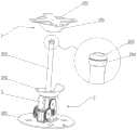
图2是本发明的对接模块与承接模块分离后的示意图。Fig. 2 is a schematic diagram of the docking module of the present invention after being separated from the receiving module.
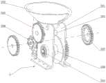
图3是本发明的收卷机构的示意图。Fig. 3 is a schematic diagram of the winding mechanism of the present invention.
图4是本发明对接套筒与承接套筒的结构示意图。Fig. 4 is a structural schematic diagram of a butt joint sleeve and a receiving sleeve of the present invention.
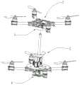
图5是本发明对接模块装配在上行飞行器上时的示意图。Fig. 5 is a schematic diagram of the docking module of the present invention assembled on an uplink aircraft.
图6是本发明承接模块装配在下行飞行器上时的示意图。Fig. 6 is a schematic diagram of the receiving module of the present invention assembled on the downlink aircraft.
图7是本发明两个飞行器的对接示意图。Fig. 7 is a schematic diagram of the docking of two aircraft of the present invention.
图8是本发明与无人艇配合作业的示意图。Fig. 8 is a schematic diagram of the cooperation between the present invention and the unmanned boat.
示意图中的标号说明:Explanation of the labels in the schematic diagram:
1、对接模块;101、第一固定架;102、对接套筒;103、导向板;104、凹型电磁铁;2、承接模块;201、第二固定架;202、承接套筒;203、卷尺钢带;204、承接座;205、凸型永磁铁;206、导向切口;207、卡槽;3、上行飞行器;4、下行飞行器;5、收卷机构;501、壳体;502、舵机;503、卷筒轴;504、辊子;505、从动齿轮;506、收卷筒;507、内棘式齿轮;508、棘爪盘。1. Docking module; 101. First fixing frame; 102. Docking sleeve; 103. Guide plate; 104. Concave electromagnet; 2. Receiving module; 201. Second fixing frame; 202. Receiving sleeve; 203. Tape measure Steel strip; 204, receiving seat; 205, convex permanent magnet; 206, guide notch; 207, slot; 3, up-flying aircraft; 4, down-flying aircraft; 5, winding mechanism; 501, shell; 502,
具体实施方式Detailed ways
以下结合附图对本发明的具体实施方式作进一步详细说明。The specific implementation manners of the present invention will be described in further detail below in conjunction with the accompanying drawings.
本发明实施例公开一种基于无人艇作业用无人飞行器共轴连接装置。The embodiment of the invention discloses a coaxial connection device for an unmanned aerial vehicle based on an unmanned boat operation.
参考图1至图8,基于无人艇作业用无人飞行器共轴连接装置包括对接模块1和承接模块2,两个上述的模块分别安装在两个组合使用的飞行器上,对接模块1安装在上行飞行器3的下端,承接模块2安装在下行飞行器4的上端,对接模块1与承接模块2可拆卸连接,通过对接模块1与承接模块2的连接,将两个飞行器装配在一起。Referring to Figures 1 to 8, the coaxial connection device for unmanned aerial vehicles based on unmanned boat operations includes a
其中,位于上方的飞行器定义为上行飞行器3,位于下方的飞行器定义为下行飞行器4,承接模块2安装在下行飞行器4的上端,对接模块1与承接模块2可拆卸连接;Wherein, the upper aircraft is defined as the
参考图2和图4,上述对接模块1包括第一固定架101和对接套筒102,第一固定架101固定连接在上行飞行器3的下端,对接套筒102固定连接在第一固定架101的下方,对接套筒102侧面设有一个导向板103,对接套筒102下端设有凹型电磁铁104;Referring to Fig. 2 and Fig. 4, the above-mentioned
参考图2、图3、图4,上述承接模块2包括第二固定架201、承接套筒202、卷尺钢带203和收卷机构5,第二固定架201固定连接在下行飞行器4的上端,收卷机构5连接在第二固定架201的上端,承接套筒202固定连接在收卷机构5上端,卷尺钢带203一端卷绕在收卷机构5中受收卷机构5控制,卷尺钢带203的另一端贯穿承接套筒202,且卷尺钢带203上端通过轴承转动连接有承接座204,承接座204上端固定连接有凸型永磁铁205;承接套筒202侧面开设有一个螺旋向下的导向切口206,导向切口206最下端开设有卡槽207。Referring to Fig. 2, Fig. 3 and Fig. 4, the above-mentioned
上述凸型永磁铁205可插接在上述凹型电磁铁104内且二者对接端的磁极相反,利用两个磁体的吸附,方便卷尺钢带203与对接模块1的连接,利用卷尺钢带203的牵引做引导,可以更加准确地完成对接模块1与承接模块2的连接。The above-mentioned convex
上述导向板103可沿着导向切口206进入到卡槽207中,通过导向板103与卡槽207的卡接,完成对接模块1和承接模块2的连接,从而防止组合后的两个飞行器拖曳重物时意外分离,增强了带载能力。The above-mentioned
进一步地,为了方便两个模块的对接,上述对接套筒102和上述承接套筒202均形如上大下小的漏斗状,对接套筒102可插接在承接套筒202内。Further, in order to facilitate the docking of the two modules, the above-mentioned
具体地,上行飞行器3与下行飞行器4对接时,对接套筒102插接在上述承接套筒202内,凹型电磁铁104与上述凸型永磁铁205对接且二者吸附在一起,导向板103沿导向切口206逐渐滑入卡槽207中,导向板103位于卡槽207内时对接套筒102与承接套筒202卡接在一起。Specifically, when the
参考图5和图6,上述对接套筒102位于上行飞行器3的轴心处,对接套筒102侧边的导向板103位于上行飞行器3的两个相邻悬臂夹角的角平分线上;上述承接套筒202位于下行飞行器4的轴心处,承接套筒202上的卡槽207与下行飞行器4的一个悬臂平行;这样两个飞行器在对接后,上行飞行器3的四个悬臂与下行飞行器4的四个悬臂相交错,组成一个八旋翼的飞行器。Referring to Fig. 5 and Fig. 6, the above-mentioned
参考图4,上述收卷机构5包括壳体501、舵机502、卷筒轴503和两个辊子504,壳体501与舵机502均固定连接在第二固定架201上,且舵机502平行设置在壳体501的一侧,卷筒轴503与两个辊子504分别转动连接在壳体501上,且靠近舵机502的辊子504的一端以及卷筒轴503上分别同轴键连接有从动齿轮505,两个从动齿轮505分别位于收卷装置的两侧,卷筒轴503上同轴固定连接有位于壳体501内的收卷筒506,收卷筒506用于收卷卷尺钢带203,卷尺钢带203经两个辊子504之间穿过,两个辊子504挤压作用在卷尺钢带203上。With reference to Fig. 4, above-mentioned winding
进一步地,为了利用一个舵机502控制两个内棘式齿轮507单独旋转,上述舵机502有两个同轴的输出轴,两个输出轴上分别同轴传动连接有内棘式齿轮507,两个输出轴上分别键连接有棘爪盘508,棘爪盘508位于内棘式齿轮507轴心处,且棘爪盘508上的棘爪作用在内棘式齿轮507上的棘齿上,两个上述内棘式齿轮507内的棘齿方向相反,上述舵机502的两个输出轴上的棘爪的朝向相同,这样舵机502正转或反转时两个内棘式齿轮507有且只有一个为主动式转动。Further, in order to use one
具体地,舵机502正转时,其中一个内棘式齿轮507呈主动式转动,带动卷筒轴503旋转,收卷筒506收卷,将卷尺钢带203收缩,而另一个内棘式齿轮507不受舵机502输出轴的控制,即此时的辊子504仅在卷尺钢带203的带动下被动地转动,这样收卷的卷尺钢带203更加的紧实、稳定。Specifically, when the
相应的,舵机502反转时,则其中一个内棘式齿轮507转动带动一个辊子504转动,使得挤压在卷尺钢带203上的两个辊子504的同步转动,从而将卷尺钢带203向上拖拽伸出,此时另一个内棘式齿轮507不受舵机502输出轴的控制,即收卷轴呈被动式放卷,这样才不会导致卷尺钢带203放卷时出现卡壳现象,使得卷尺钢带203能平稳地向上延伸。Correspondingly, when the
进一步地,上述卷尺刚带由两个相同片卷尺拼接而成,卷尺钢带203的外面包裹有热缩管。Further, the steel measuring tape is formed by splicing two identical tapes, and the
进一步地,也可以在壳体501上现有的两个辊子504上方再设置两个辊子504,这样可以更好的对卷尺钢带203起到引导作用。Further, two
需要强调的一点是,飞行器的操控系统、通信系统均属于现有技术,飞行器的悬停、旋转以及对电磁铁和舵机502的远程控制均可采用现有技术得以实现,在此不做过多赘述,本发明仅对两个飞行器对接用的机械结构进行设计,以更好完成两个飞行器的稳定对接。It should be emphasized that the control system and communication system of the aircraft belong to the existing technology, and the hovering and rotation of the aircraft, as well as the remote control of the electromagnet and the
两个飞行器在空中的对接方式如下:The docking method of two aircraft in the air is as follows:
在无人艇上携带有至少两个飞行器,其中,两个飞行器各自行飞行作业,携带对接模块1的飞行器为上行飞行器3,携带承接模块2的飞行器为下行飞行器4(如图8所示);At least two aircraft are carried on the unmanned boat, wherein, the two aircraft operate independently, the aircraft carrying the
当拖曳重物时,需要将两个飞行器拼接使用,首先,将下行飞行器4悬停,远程启动舵机502使其反转,两个棘爪盘508旋转,其中一个棘爪盘508带动着一个内棘式齿轮507转动,该内棘式齿轮507通过从动齿轮505带动辊子504旋转,在多个辊子504挤压转动作用下,从而将卷尺钢带203向上移动,而此时,收卷轴则不受舵机502的控制,在卷尺刚带的拉动下自由地转动,从而引导卷尺钢带203顺畅地向上拖拽,卷尺钢带203脱离辊子504挤压的部分竖直地插接在承接套筒202内部,等待与上行飞行器3对接;When towing heavy objects, two aircrafts need to be spliced and used. First, the
然后,上行飞行器3移动至下行飞行器4的上方后再缓慢下移,同时将凹型电磁铁104上电充磁,利用磁力,凹型电磁铁104可轻易与凸型永磁铁205吸附在一起,完成两个飞行器的初步对接;Then, the
而后,再控制舵机502反向转动,卷尺钢带203收卷,拖动上行飞行器3向下行飞行器4靠近,直至对接套筒102插接在承接甜筒内部,完成对接;Then, the
最后,操控上行飞行器3旋转,由于凸型永磁体与承接座204可以在收卷钢带上转动,因此,在两个磁铁吸附在一起时,上行飞行器3仍可以带着对接套筒102同步转动,同时在卷尺钢带203的拖拽下,使得导向板103沿着导向切口206逐渐下移,直至导向板103卡接在卡槽207内,完成对接套筒102与承接套筒202的卡接,从而将两个飞行器固定连接在一起。Finally, control the
当需要将两个飞行器分离时,首先,将凹型电磁铁104断电消磁,然后,上行飞行器3旋转,将导向板103从卡槽207内脱离,而后即可将对接套筒102与承接套筒202分离,两个飞行器完成分离。When it is necessary to separate the two aircraft, first, the
本发明通过对接模块1和承接模块2的配合设置,对接套筒102上的导向板103可以顺畅地沿着承接套筒202上的导向切口206滑入到卡槽207内,从而将对接套筒102与承接套筒202卡接在一起,实现两个飞行器的固定连接,降低了对接难度,且导向板103与卡槽207的位置限定了两个飞行器对接后的位置,使得两个飞行器共计八个悬臂相交错布置,组成一个八旋翼的飞行器,提高带载能力。通过卷尺钢带203和舵机502的配合设置,利用棘爪棘齿结构实现两个内棘式齿轮507的单独控制,从而更加稳定地对卷尺钢带203进行收放卷;且卷尺钢带203上的凸型永磁体与对接套筒102下端的凹型电磁铁104吸附后,利用卷尺钢带203的牵引,能够更好的引导上行飞行器3与下行飞行器4的对接,在配合无人艇海上作业时,能够抵抗海上风浪对飞行器的影响,提高两个飞行器对接成功率。In the present invention, through the cooperative arrangement of the
可见,利用本发明所提供的基于无人艇作业用无人飞行器共轴连接装置,可以有效解决两个飞行器在空中对接困难,及连接处不稳定的问题。It can be seen that using the coaxial connection device for unmanned aerial vehicles based on unmanned boat operations provided by the present invention can effectively solve the problems of difficult docking of two aircrafts in the air and unstable connections.
以上上述实施例仅表达了本发明的几种实施方式,其描述较为具体和详细,但并不能因此而理解为对本发明范围的限制。应当指出的是,对于本领域的普通技术人员来说,在不脱离本发明构思的前提下,还可以做出若干变形和改进,这些都属于本发明的保护范围。因此,本发明专利的保护范围应以所附权利要求为准。The above-mentioned embodiments only express several implementations of the present invention, and the description thereof is relatively specific and detailed, but should not be construed as limiting the scope of the present invention. It should be noted that, for those skilled in the art, several modifications and improvements can be made without departing from the concept of the present invention, and these all belong to the protection scope of the present invention. Therefore, the protection scope of the patent for the present invention should be based on the appended claims.
Claims (7)
Translated fromChinesePriority Applications (1)
| Application Number | Priority Date | Filing Date | Title |
|---|---|---|---|
| CN202310109380.1ACN116409475B (en) | 2023-02-13 | 2023-02-13 | Unmanned aerial vehicle coaxial connecting device for unmanned ship operation |
Applications Claiming Priority (1)
| Application Number | Priority Date | Filing Date | Title |
|---|---|---|---|
| CN202310109380.1ACN116409475B (en) | 2023-02-13 | 2023-02-13 | Unmanned aerial vehicle coaxial connecting device for unmanned ship operation |
Publications (2)
| Publication Number | Publication Date |
|---|---|
| CN116409475Atrue CN116409475A (en) | 2023-07-11 |
| CN116409475B CN116409475B (en) | 2025-08-15 |
Family
ID=87055570
Family Applications (1)
| Application Number | Title | Priority Date | Filing Date |
|---|---|---|---|
| CN202310109380.1AActiveCN116409475B (en) | 2023-02-13 | 2023-02-13 | Unmanned aerial vehicle coaxial connecting device for unmanned ship operation |
Country Status (1)
| Country | Link |
|---|---|
| CN (1) | CN116409475B (en) |
Citations (5)
| Publication number | Priority date | Publication date | Assignee | Title |
|---|---|---|---|---|
| CN108045580A (en)* | 2018-01-17 | 2018-05-18 | 广东工业大学 | Double UAV system of battery are replaced in a kind of aerial docking |
| US20200031438A1 (en)* | 2018-07-25 | 2020-01-30 | Thomas Lawrence Moses | Unmanned Aerial Vehicle Search and Rescue System |
| CN211032239U (en)* | 2019-11-12 | 2020-07-17 | 天津三川同大科技发展有限公司 | Unmanned aerial vehicle battery replacing device and system |
| CN114261473A (en)* | 2021-12-09 | 2022-04-01 | 武汉理工大学 | Connector mechanism for unmanned boat docking |
| CN216929068U (en)* | 2021-12-29 | 2022-07-08 | 南京傲宁数据科技有限责任公司 | Accurate butt joint hardware structure of son and mother machine that charges in air of four rotor unmanned aerial vehicle |
- 2023
- 2023-02-13CNCN202310109380.1Apatent/CN116409475B/enactiveActive
Patent Citations (5)
| Publication number | Priority date | Publication date | Assignee | Title |
|---|---|---|---|---|
| CN108045580A (en)* | 2018-01-17 | 2018-05-18 | 广东工业大学 | Double UAV system of battery are replaced in a kind of aerial docking |
| US20200031438A1 (en)* | 2018-07-25 | 2020-01-30 | Thomas Lawrence Moses | Unmanned Aerial Vehicle Search and Rescue System |
| CN211032239U (en)* | 2019-11-12 | 2020-07-17 | 天津三川同大科技发展有限公司 | Unmanned aerial vehicle battery replacing device and system |
| CN114261473A (en)* | 2021-12-09 | 2022-04-01 | 武汉理工大学 | Connector mechanism for unmanned boat docking |
| CN216929068U (en)* | 2021-12-29 | 2022-07-08 | 南京傲宁数据科技有限责任公司 | Accurate butt joint hardware structure of son and mother machine that charges in air of four rotor unmanned aerial vehicle |
Also Published As
| Publication number | Publication date |
|---|---|
| CN116409475B (en) | 2025-08-15 |
Similar Documents
| Publication | Publication Date | Title |
|---|---|---|
| CN111361739A (en) | Transmission line inspection drone and transmission line inspection system | |
| CN109626143A (en) | One kind being tethered at UAV Intelligent take-up and pay-off device and its working method | |
| US8104419B2 (en) | Device for automatically attaching and detaching a towed sonar transmitter to and from an active-sonar tow line | |
| CN111717736A (en) | Retracting and unwinding assembly of tethered drone, ground recovery device and recovery method | |
| EP0060571B1 (en) | Web threading apparatus | |
| CN113148019B (en) | Recovery system and recovery method for autonomous underwater robot for autonomous recovery on water surface | |
| CN116409475A (en) | Coaxial connection device for unmanned aerial vehicles based on unmanned boat operations | |
| CN215707223U (en) | A receive and release line device for mooring unmanned aerial vehicle | |
| CN217100507U (en) | Unmanned aerial vehicle carrier-borne auxiliary recovery device | |
| CN220264506U (en) | Automatic threading device and coating machine | |
| CN210528126U (en) | Electric winder for unmanned submersible | |
| CN209618592U (en) | One kind being tethered at UAV Intelligent take-up and pay-off device | |
| CN218228339U (en) | Printing and drying device for packaging bag | |
| CN109704155A (en) | A simple tethered unmanned aerial vehicle automatic retracting and releasing device | |
| CN213011370U (en) | Automatic take-up and pay-off winch device for mooring unmanned aerial vehicle | |
| CN209242379U (en) | A kind of simple type is tethered at unmanned plane automatic deploying and retracting line apparatus | |
| CN115076582A (en) | Automatic cable traction device of track shooting robot suitable for straight rails and curved rails | |
| CN209815411U (en) | Automatic winding and unwinding device for staying unmanned aerial vehicle | |
| CN112027031B (en) | Throwing device for life saving of ocean passenger ship | |
| CN212475666U (en) | Flat type mooring unmanned aerial vehicle take-up and pay-off device | |
| CN214451765U (en) | Cable communication device and diving equipment with same | |
| CN211034763U (en) | Offshore engineering shipborne reconnaissance equipment winding and unwinding devices for platform | |
| CN107147038A (en) | A self-absorbing traction line restraint device | |
| CN117228448B (en) | Steel wire overlapping winder of electric projection screen | |
| CN209777984U (en) | Unmanned aerial vehicle constant tension small take-up and pay-off winch |
Legal Events
| Date | Code | Title | Description |
|---|---|---|---|
| PB01 | Publication | ||
| PB01 | Publication | ||
| SE01 | Entry into force of request for substantive examination | ||
| SE01 | Entry into force of request for substantive examination | ||
| GR01 | Patent grant | ||
| GR01 | Patent grant |