CN116408514A - Vacuum adsorption system for electronic components - Google Patents
Vacuum adsorption system for electronic componentsDownload PDFInfo
- Publication number
- CN116408514A CN116408514ACN202111681377.4ACN202111681377ACN116408514ACN 116408514 ACN116408514 ACN 116408514ACN 202111681377 ACN202111681377 ACN 202111681377ACN 116408514 ACN116408514 ACN 116408514A
- Authority
- CN
- China
- Prior art keywords
- hole
- vacuum
- base
- holes
- electronic components
- Prior art date
- Legal status (The legal status is an assumption and is not a legal conclusion. Google has not performed a legal analysis and makes no representation as to the accuracy of the status listed.)
- Granted
Links
Images


Classifications
- B—PERFORMING OPERATIONS; TRANSPORTING
- B23—MACHINE TOOLS; METAL-WORKING NOT OTHERWISE PROVIDED FOR
- B23K—SOLDERING OR UNSOLDERING; WELDING; CLADDING OR PLATING BY SOLDERING OR WELDING; CUTTING BY APPLYING HEAT LOCALLY, e.g. FLAME CUTTING; WORKING BY LASER BEAM
- B23K3/00—Tools, devices, or special appurtenances for soldering, e.g. brazing, or unsoldering, not specially adapted for particular methods
- B23K3/08—Auxiliary devices therefor
- B—PERFORMING OPERATIONS; TRANSPORTING
- B25—HAND TOOLS; PORTABLE POWER-DRIVEN TOOLS; MANIPULATORS
- B25J—MANIPULATORS; CHAMBERS PROVIDED WITH MANIPULATION DEVICES
- B25J15/00—Gripping heads and other end effectors
- B25J15/06—Gripping heads and other end effectors with vacuum or magnetic holding means
- B25J15/0616—Gripping heads and other end effectors with vacuum or magnetic holding means with vacuum
- B—PERFORMING OPERATIONS; TRANSPORTING
- B65—CONVEYING; PACKING; STORING; HANDLING THIN OR FILAMENTARY MATERIAL
- B65G—TRANSPORT OR STORAGE DEVICES, e.g. CONVEYORS FOR LOADING OR TIPPING, SHOP CONVEYOR SYSTEMS OR PNEUMATIC TUBE CONVEYORS
- B65G47/00—Article or material-handling devices associated with conveyors; Methods employing such devices
- B65G47/74—Feeding, transfer, or discharging devices of particular kinds or types
- B65G47/90—Devices for picking-up and depositing articles or materials
- B65G47/91—Devices for picking-up and depositing articles or materials incorporating pneumatic, e.g. suction, grippers
Landscapes
- Engineering & Computer Science (AREA)
- Mechanical Engineering (AREA)
- Robotics (AREA)
- Manipulator (AREA)
Abstract
Description
Translated fromChinese技术领域technical field
本发明涉及气动技术领域,尤其涉及电子元器件用真空吸附系统。The invention relates to the field of pneumatic technology, in particular to a vacuum adsorption system for electronic components.
背景技术Background technique
目前,真空吸盘作为用于吸取零部件的重要的气动部件,广泛应用于自动化设备当中。在这些设备当中,真空吸盘起到机械手的末端的手指的作用,能够用于吸取例如:晶圆、芯片等片状且轻盈的电子元器件。At present, vacuum chucks are widely used in automation equipment as an important pneumatic component for sucking parts. Among these devices, the vacuum chuck acts as the finger at the end of the manipulator, and can be used to pick up flake and light electronic components such as wafers and chips.
以芯片为例,芯片有时候会被载置在载盘中,从而进行上料。一个载盘中会载置非常多的芯片,芯片以一定的间隔在载盘中放置。此外,芯片会通过真空吸盘搬运到不同的电路板中并进行焊接。为了提高生产效率,通常会设置真空吸盘组,同时吸附多个电子元器件并进行上料。现有的真空吸附装置一般都是使用真空发生器,并通过并联的方式控制多个真空吸盘,即通过一个气源同时控制多个真空吸盘的通断。然而,在有些情况下,由于装配工序的变更,例如装配位置等的变更,存在部分真空吸盘不需要工作的情况。在此情况下,并联连接的真空吸盘组当中,由于部分真空吸盘不工作(破真空),这可能导致真空吸盘组整体吸附失败。Taking chips as an example, chips are sometimes placed on a tray for loading. A very large number of chips are placed on one tray, and the chips are placed on the tray at certain intervals. In addition, chips are transported by vacuum chucks to different circuit boards and soldered. In order to improve production efficiency, a set of vacuum suction cups is usually set up to absorb and load multiple electronic components at the same time. Existing vacuum adsorption devices generally use vacuum generators to control multiple vacuum chucks in parallel, that is, to simultaneously control the on-off of multiple vacuum chucks through one air source. However, in some cases, due to changes in the assembly process, such as changes in the assembly position, there are cases where some vacuum chucks do not need to work. In this case, among the vacuum chuck groups connected in parallel, because some of the vacuum chucks do not work (break the vacuum), this may cause the overall suction failure of the vacuum chuck group.
此外,由于例如芯片、晶圆等的电子元器件的厚度非常薄且容易破碎,现有的真空吸盘在吸附这些薄且易碎的电子元器件时,经常会出现由于真空吸盘抵接产品的力度过大等导致部件破碎的情况。In addition, since electronic components such as chips and wafers are very thin and easily broken, when the existing vacuum chuck absorbs these thin and fragile electronic components, it often occurs due to the strength of the vacuum chuck against the product. Parts are broken due to excessive size, etc.
发明内容Contents of the invention
本发明旨在至少一定程度上解决现有技术问题之一。为此,本发明提出了真空吸附系统,能够容易地兼容电子元器件的不同的装配工序。The present invention aims at solving one of the problems of the prior art, at least to some extent. For this reason, the present invention proposes a vacuum adsorption system, which can be easily compatible with different assembly processes of electronic components.
根据本发明一方面的电子元器件用真空吸附系统,包括:真空发生部,所述真空发生部具有:第一基座、多个真空发生器和多个调节开关,其中,各所述真空发生器分别容置在所述第一基座内,并分别通过所述调节开关而独立地被封堵或者被打开;多个缓冲装置,各所述缓冲装置分别具有:呈筒状的第二基座和滑动杆,所述滑动杆的轴向的一端容置在所述第二基座内并相对所述第二基座沿轴向可滑动,所述第二基座和所述滑动杆共同形成气路通道,各所述第二基座和各所述真空发生器一一对应并通过气管连接;多个真空吸盘,各所述真空吸盘和各所述缓冲装置一一对应,各所述真空吸盘分别具有:第三基座和设置在所述第三基座上的吸附件,所述第三基座安装到所述滑动杆的轴向的另一端并和所述气路通道连通,所述吸附件的材料为邵氏硬度A在40度以下的海绵材料,且在未受压的情况下,所述吸附件的厚度为5mm以上。The vacuum adsorption system for electronic components according to one aspect of the present invention includes: a vacuum generating part, the vacuum generating part has: a first base, a plurality of vacuum generators and a plurality of adjustment switches, wherein each of the vacuum generating The devices are respectively accommodated in the first base, and are independently blocked or opened by the adjustment switch; a plurality of buffer devices, each of which has a cylindrical second base a seat and a sliding rod, one axial end of the sliding rod is accommodated in the second base and can slide axially relative to the second base, and the second base and the sliding rod jointly An air channel is formed, each of the second bases corresponds to each of the vacuum generators and is connected through a gas pipe; a plurality of vacuum suction cups, each of the vacuum suction cups corresponds to each of the buffer devices, and each of the vacuum suction cups corresponds to each of the buffer devices. The vacuum chucks respectively have: a third base and an adsorption piece arranged on the third base, the third base is installed on the other axial end of the sliding rod and communicated with the air channel, The material of the adsorbent is a sponge material with a Shore A hardness of less than 40 degrees, and the thickness of the adsorbent is more than 5mm under the condition of no pressure.
根据本发明一方面的真空吸附系统,具有如下有益效果:能够容易地兼容电子元器件的不同的装配工序。The vacuum adsorption system according to one aspect of the present invention has the following beneficial effects: it can be easily compatible with different assembly processes of electronic components.
在一些实施例中,所述第一基座开设有:第一孔部,用于和外设高压气源连接,多个第二孔部,所述真空发生器分别容置在所述第二孔部内,多个第三孔部,各所述第三孔部分别将各所述第二孔部和所述第一孔部连通,多个第四孔部,用于和所述气路通道连通,各所述第四孔部分别连通各所述第二孔部,并且,在所述第二孔部内容置有所述真空发生器的状态下,各所述第四孔部分别和各所述真空发生器的吸附端相对;各所述调节开关分别设置有容置在所述第三孔部内的第一端部,所述第一端部沿所述第三孔部的轴向可进给以将所述第一孔部和所述第二孔部之间封堵或者打开。In some embodiments, the first base is provided with: a first hole for connecting with an external high-pressure gas source, a plurality of second holes, the vacuum generators are respectively accommodated in the second In the hole part, there are a plurality of third hole parts, each of the third hole parts communicates with each of the second hole parts and the first hole part, and a plurality of fourth hole parts are used to communicate with the gas path Each of the fourth holes communicates with each of the second holes, and, in the state where the vacuum generator is placed in the second hole, each of the fourth holes is connected to each of the second holes. The suction ends of the vacuum generators are opposite; each of the adjustment switches is respectively provided with a first end portion accommodated in the third hole portion, and the first end portion can be moved along the axial direction of the third hole portion. Feed to seal or open between the first hole and the second hole.
在一些实施例中,所述第一孔部沿第一方向延伸,所述第一方向平行于所述第一基座的长度方向;所述第二孔部沿第二方向延伸,所述第二方向平行于所述第一基座的宽度方向且正交于所述第一方向;所述第三孔部沿第三方向延伸,所述第三方向平行于所述第一基座的高度方向且分别正交于所述第一方向和所述第二方向;所述第四孔部沿所述第三方向延伸。In some embodiments, the first hole extends along a first direction, and the first direction is parallel to the length direction of the first base; the second hole extends along a second direction, and the first The two directions are parallel to the width direction of the first base and orthogonal to the first direction; the third hole extends along a third direction, and the third direction is parallel to the height of the first base directions and are respectively perpendicular to the first direction and the second direction; the fourth hole extends along the third direction.
在一些实施例中,所述第一基座上还开设有多个出气部,各所述出气部分别连通各所述第二孔部,并且,在所述真空发生器容置在所述第二孔部内的状态下,各所述出气部分别和各所述真空发生器的出气端连通。In some embodiments, a plurality of air outlets are provided on the first base, each of the air outlets communicates with each of the second holes, and when the vacuum generator is accommodated in the first In the state of the two holes, each of the air outlets communicates with the air outlet of each of the vacuum generators.
在一些实施例中,所述气路通道包括沿轴向贯通所述第二基座的第六孔部以及沿轴向贯通所述滑动杆的第七孔部,所述第六孔部和所述第七孔部连通;所述第六孔部的轴向的一端密封地安装有第三气管接头,所述第三气管接头通过所述气管和所述真空发生器连接;所述滑动杆至少部分容置在所述第六孔部内且相对所述第六孔部沿轴向可滑动;在所述滑动杆沿远离所述第三气管接头的方向滑动时,所述滑动杆的一部分穿过所述第六孔部的轴向的另一端而显露在所述第二基座之外;所述缓冲装置还包括弹性件,所述弹性件以压缩的状态一端抵接所述滑动杆且另一端抵接所述第二基座。In some embodiments, the air channel includes a sixth hole passing through the second base in the axial direction and a seventh hole passing through the sliding rod in the axial direction, the sixth hole and the The seventh hole is connected; the axial end of the sixth hole is sealed with a third air pipe joint, and the third air pipe joint is connected to the vacuum generator through the air pipe; the sliding rod is at least Part is housed in the sixth hole and is axially slidable relative to the sixth hole; when the sliding rod slides in a direction away from the third tracheal joint, a part of the sliding rod passes through The other end of the axial direction of the sixth hole is exposed outside the second base; the buffer device further includes an elastic member, and one end of the elastic member abuts against the sliding rod in a compressed state and the other end One end abuts against the second base.
在一些实施例中,所述第六孔部的内壁上设置有限制部,所述滑动杆的容置在所述第六孔部内的部分设置有多边形部,所述多边形部在所述第六孔部内沿周向被所述限制部限制。In some embodiments, the inner wall of the sixth hole is provided with a restricting part, and the part of the sliding rod accommodated in the sixth hole is provided with a polygonal part, and the polygonal part is located in the sixth hole. The inside of the hole is restricted in the circumferential direction by the restricting portion.
在一些实施例中,所述限制部包括开设在所述内壁上的多个第二槽部,多个所述第二槽部沿所述内壁的周向间隔分布,各所述第二槽部分别沿所述第六孔部的轴向延伸;所述多边形部的边角部分别容置在所述第二槽部内,并可沿所述第二槽部滑动。In some embodiments, the restricting portion includes a plurality of second grooves opened on the inner wall, and the plurality of second grooves are distributed along the circumferential direction of the inner wall at intervals, each of the second grooves respectively extend along the axial direction of the sixth hole; the corners of the polygonal portion are respectively accommodated in the second groove and can slide along the second groove.
在一些实施例中,所述第三基座的一侧开设有有用于和所述气路通道连通的第八孔部,所述第三基座的另一侧开设有多个第九孔部,所述第九孔部和所述第八孔部连通;所述吸附件上开设有多个第十孔部,各所述第十孔部分别和各所述第九孔部一一相对。In some embodiments, one side of the third base is provided with an eighth hole for communicating with the air channel, and the other side of the third base is provided with a plurality of ninth holes. , the ninth hole communicates with the eighth hole; a plurality of tenth holes are opened on the adsorbent, and each of the tenth holes is opposite to each of the ninth holes.
在一些实施例中,所述吸附件的材料为发泡海绵材料,所述吸附件的邵氏硬度A为28度以上且32度以下。In some embodiments, the material of the adsorbent is a foamed sponge material, and the Shore A hardness of the adsorbent is not less than 28 degrees and not more than 32 degrees.
在一些实施例中,所述吸附件的厚度为12mm以下。In some embodiments, the thickness of the adsorbent is less than 12 mm.
附图说明Description of drawings
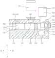
图1是本发明的第一方面的真空发生器用真空发生部的一种实施例的左侧视角的立体图。Fig. 1 is a left side perspective view of an example of a vacuum generating unit for a vacuum generator according to the first aspect of the present invention.
图2是图1的真空发生器用真空发生部的右侧视角的立体图。Fig. 2 is a right side perspective view of the vacuum generating part for the vacuum generator in Fig. 1 .
图3是图1中的第一基座的左侧视角的立体图。FIG. 3 is a perspective view from the left side of the first base in FIG. 1 .
图4是图1中的第一基座的右侧视角的立体图。FIG. 4 is a perspective view from the right side of the first base in FIG. 1 .
图5是图1中的A-A处的剖视图。Fig. 5 is a cross-sectional view at A-A in Fig. 1 .
图6是本发明第二方面的真空吸附装置的一种实施例的示意图。Fig. 6 is a schematic diagram of an embodiment of the vacuum adsorption device of the second aspect of the present invention.
图7是图1的缓冲装置的示意图。FIG. 7 is a schematic diagram of the buffer device of FIG. 1 .
图8是图7中的B-B处的剖视图。Fig. 8 is a cross-sectional view along line B-B in Fig. 7 .
图9是缓冲装置的另一种实施例的示意图。Fig. 9 is a schematic diagram of another embodiment of the buffer device.
图10是缓冲装置的又一种实施例的示意图。Fig. 10 is a schematic diagram of another embodiment of the buffer device.
图11是图7中的C-C处的剖视图。Fig. 11 is a sectional view at line C-C in Fig. 7 .
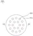
图12是图1的真空吸盘的仰视图。Fig. 12 is a bottom view of the vacuum chuck of Fig. 1 .
图13是图12中的D-D处的剖视图。Fig. 13 is a cross-sectional view taken along line D-D in Fig. 12 .
具体实施方式Detailed ways
以下将结合实施例对本实施方式的构思及产生的技术效果进行清楚、完整地描述,以充分地理解本实施方式的目的、特征和效果。显然,所描述的实施例只是本实施方式的一部分实施例,而不是全部实施例,基于本实施方式的实施例,本领域的技术人员在不付出创造性劳动的前提下所获得的其他实施例,均属于本实施方式保护的范围。The idea and technical effects of this embodiment will be clearly and completely described below in conjunction with examples, so as to fully understand the purpose, features and effects of this embodiment. Apparently, the described embodiments are only some of the embodiments of this implementation mode, rather than all of them. Based on the examples of this implementation mode, other embodiments obtained by those skilled in the art without paying creative efforts, All belong to the scope of protection of this embodiment.
在本实施方式实施例的描述中,如果涉及到方位描述,例如“上”、“下”、“前”、“后”、“左”、“右”等指示的方位或位置关系为基于附图所示的方位或位置关系,仅是为了便于描述本实施方式和简化描述,而不是指示或暗示所指的装置或元件必须具有特定的方位、以特定的方位构造和操作,因此不能理解为对本实施方式的限制。In the description of the examples of this embodiment, if it involves orientation descriptions, for example, the orientations or positional relationships indicated by "up", "down", "front", "back", "left", "right" are based on the attached The orientation or positional relationship shown in the figure is only for the convenience of describing the present embodiment and simplifying the description, and does not indicate or imply that the referred device or element must have a specific orientation, be constructed and operated in a specific orientation, and therefore cannot be understood as Restrictions on this embodiment.
在本实施方式实施例的描述中,如果某一特征被称为“设置”、“固定”、“连接”、“安装”在另一个特征,它可以直接设置、固定、连接在另一个特征上,也可以间接地设置、固定、连接、安装在另一个特征上。在本实施方式实施例的描述中,如果涉及到“若干”,其含义是一个以上,如果涉及到“多个”,其含义是两个以上,如果涉及到“大于”、“小于”、“超过”,均应理解为不包括本数,如果涉及到“以上”、“以下”、“以内”,均应理解为包括本数。如果涉及到“第一”、“第二”,应当理解为用于区分技术特征,而不能理解为指示或暗示相对重要性或者隐含指明所指示的技术特征的数量或者隐含指明所指示的技术特征的先后关系。In the description of an example of this embodiment, if a certain feature is referred to as being "set", "fixed", "connected", "installed" on another feature, it can be directly set, fixed, or connected on another feature , can also be indirectly set, fixed, connected, mounted on another feature. In the description of the examples of this embodiment, if it involves "several", it means more than one, if it involves "multiple", it means more than two, if it involves "greater than", "less than", " "Exceeding" shall be understood as excluding the original number, and if "above", "below" and "within" are involved, it shall be understood as including the original number. If "first" and "second" are involved, it should be understood as used to distinguish technical features, and should not be understood as indicating or implying relative importance or implicitly indicating the number of indicated technical features or implicitly indicating the indicated The sequence of technical features.
根据本实施方式的电子元器件用真空吸附系统,包括:真空发生部100、多个缓冲装置200以及多个真空吸盘300。The vacuum adsorption system for electronic components according to this embodiment includes: a
其中,真空发生部100具有:第一基座101、多个真空发生器121和多个调节开关102,各真空发生器121分别容置在第一基座101内,并分别通过调节开关102而独立地被封堵或者被打开。Wherein, the
其中,各缓冲装置200分别具有:呈筒状的第二基座201和滑动杆203。滑动杆203的轴向的一端容置在第二基座201内并相对第二基座201沿轴向可滑动。第二基座201和滑动杆203共同形成气路通道221。各第二基座201和各真空发生器121一一对应并通过气管222连接。Wherein, each
其中,各真空吸盘300和各缓冲装置200一一对应。各真空吸盘300分别具有:第三基座301和设置在第三基座301上的吸附件302。第三基座301安装到滑动杆203的轴向的另一端并和气路通道221连通。吸附件302的材料为邵氏硬度A在40度以下的海绵材料,且在未受压的情况下,吸附件302的厚度为5mm以上。Wherein, each
根据本实施方式的电子元器件用真空吸附系统,能够容易地兼容电子元器件的不同的装配工序。具体而言,在真空发生部100中,由于将真空发生器121安装在第一基座101内,并通过调节开关102独立地使真空发生器121被封堵或者被打开,因此,能够独立地控制各真空发生器121的通断。通过设置多个真空吸盘300,能够吸附多个例如芯片等的电子元器件,并将这些电子元器件同时转移到例如电路板中。此外,当电子元器件需要适应不同的电路板、例如电路板的部分位置不需要安装电子元器件时,只需要通过调节开关102封堵与电路板的该位置对应的真空吸盘300即可,因此,本实施方式的真空吸附系统能够容易地兼容电子元器件的不同的装配工序。According to the vacuum suction system for electronic components of the present embodiment, it is possible to easily accommodate different assembly processes of electronic components. Specifically, in the
此外,通过将连接真空发生器121和缓冲装置200的气管222安装到缓冲装置200的第二基座201中,由于该第二基座201不需要滑动,因此,能够抑制气管222随着滑动杆203的滑动而折弯或者缠绕等,即使在存在多个真空吸盘300以及多个缓冲装置200的情况下,也能够抑制气管222的折弯或者缠绕。In addition, by installing the
进一步地,由于真空吸盘300使用邵氏硬度A在40度以下的海绵材料作为吸附件302,因此能够至少一定程度上抑制真空吸盘300抵接例如芯片、晶圆等的电子元器件时候的作用力,降低真空吸盘300将电子元器件压碎的风险。Further, since the
以下,分别对本实施方式的真空吸附系统的各部件进行详细说明。Each component of the vacuum adsorption system of this embodiment will be described in detail below.
[真空发生部100][vacuum generator 100]
图2、图3是真空发生部100的立体图,图4、图5是第一基座101的立体图,图6是图2中的A-A处的剖视图。在图2至图6中,为了便于说明,赋予了方向上的示意。2 and 3 are perspective views of the
参照图2至图6,并辅助参照图1,真空发生部100的如上所述,真空发生部100包括:第一基座101、多个真空发生器121和多个调节开关102,各真空发生器121分别容置在第一基座101内。具体地,参照图2至图6,真空发生部100包括:第一基座101和多个调节开关102。其中,第一基座101开设有:第一孔部103、多个第二孔部104、多个第三孔部105以及多个第四孔部106。其中,在第一基座101中,第一孔部103用于和外设高压气源107连接。各第二孔部104分别用于容置真空发生器121。各第三孔部105分别将各第二孔部104和第一孔部103连通。各第四孔部106用于和缓冲装置200的气路通道221(辅助参照图8)连通。各第四孔部106分别连通各第二孔部104,并且,在第二孔部104内容置有真空发生器121的状态下,各第四孔部106分别和各真空发生器121的吸附端124相对。各调节开关102分别设置有容置在第三孔部105内的第一端部108,第一端部108沿第三孔部105的轴向可进给以将第一孔部103和第二孔部104之间封堵或者打开。Referring to Fig. 2 to Fig. 6, and auxiliary reference to Fig. 1, the
继续参照图6,本实施方式的真空发生器121,例如可以是圆筒状的真空发生器121,真空发生器121的轴向的一端,设置有进气端122,轴向的另一端设置有出气端123,吸附端124设置在出气端123和进气端122之间。此外,出气端123可以连接消音器(未图示)。在真空发生器121容置在第二孔部104的情况下,真空发生器121的轴向的一端的进气端122位于第二孔部104的和第一孔部103相邻的一侧,真空发生器121的轴向的另一端的出气端123位于第二孔部104的朝向第一基座101的外侧(附图中为左侧)的一端,吸附端124则和第四孔部106相对并连通。此外,真空发生器121的外周可以套嵌有例如两个第一密封圈125,两个第一密封圈125例如沿轴向分别套嵌在吸附端124的两侧,由此,能够提高真空发生器121的吸附端124和第一基座101之间的密封性能。Continuing to refer to Fig. 6, the
继续参照图4、图5,并辅助参照图2、图3,第一基座101例如呈长方体形状的块状。为了合理地布局各孔部的结构,在一些实施例中,第一孔部103沿第一方向(附图中为前后方向)延伸,第一方向平行于第一基座101的长度方向。为了便于加工第一孔部103,第一孔部103可以沿第一方向直接贯通第一基座101。第一孔部103在第一基座101的具体的开设位置并不特别限定,例如可以开设在第一基座101的右下方。第一孔部103的轴向的一端可以安装第一堵头(未图示,位于第一基座101的前面侧),第一孔部103的轴向的另一端则可以安装用于安装气管222的第一气管接头109。With continued reference to FIG. 4 and FIG. 5 , and supplementary reference to FIG. 2 and FIG. 3 , the
继续参照图4,并辅助参照图2,为了容易地布局第二孔部104,第二孔部104沿第二方向(附图中为左右方向)延伸,第二方向平行于第一基座101的宽度方向且正交于第一方向。第二孔部104例如可以从第一基座101的左侧的靠近上部的一侧,朝第一基座101的右侧延伸。此外,第二孔部104可以不贯通第一基座101。第二孔部104的数量并不特别限定,根据所需要安装的真空发生器121的数量确定即可。例如,第二孔部104的数量可以包括6个至8个。第二孔部104可以沿第一基座101的第一方向均匀地间隔分布。第二孔部104的位于第一基座101的左侧的一端可以用于真空发生器121的出气端123的排气。此外,在第一基座101上开设有用于真空发生器121排气的出气部110(后述)开设在其他位置的情况下,也可以将第二孔部104封堵,例如,第二孔部104的位于第一基座101的左侧的一端可以通过第二堵头111进行封堵。Continuing to refer to FIG. 4 , and with auxiliary reference to FIG. 2 , in order to easily lay out the
继续参照图6,第三孔部105根据第一孔部103和各第二孔部104的位置而适当地开设。第三孔部105例如可以沿第三方向(附图中为上下方向)延伸,第三方向平行于第一基座101的高度方向且分别正交于第一方向和第二方向。为了容易地将第二孔部104和第一孔部103连通,第三孔部105从第一基座101的上表面的靠近右侧的位置开设。第三孔部105的直径和深度并不特别限定,例如,第三孔部105的轴向的一端贯通第一孔部103的壁部以和第一孔部103连通。此外,第二孔部104的轴向的一端贯通第三孔部105的壁部以和第三孔部105连通。即,第三孔部105朝下延伸的深度只要能够贯通第一孔部103的壁部即可。此外,第二孔部104的朝右方向延伸的深度只要能够贯通第三孔部105的壁部即可。由此,第三孔部105的轴向的下端部和第一孔部103连通,第二孔部104的轴向的右端部则在第三孔部105的壁部处和第三孔部105连通。通过使第三孔部105的下端部和第一孔部103连通且第三孔部105的壁部和第二孔部104的右端部连通,能够容易地实现通过调节开关102封堵或者打开第三孔部105的下端部和/或第二孔部104的右端部,从而容易地实现第一孔部103和第三孔部105之间的封堵或者打开。Continuing to refer to FIG. 6 , the
继续参照图6,并辅助参照图2、图3,第四孔部106例如也可以沿第三方向延伸。具体地,第四孔部106可以根据真空发生器121的吸附端124的吸附孔的位置适当设置即可。为了容易地安装用于连接气管222连接的第二气管接头112,第四孔部106例如可以从第一基座101的上表面的大致左右方向的中部,朝下方向开设。第四孔部106例如可以是螺纹孔。With continued reference to FIG. 6 and auxiliary reference to FIGS. 2 and 3 , the
继续参照图6,并辅助参照图2至图5,此外,在一些实施例中,为了便于真空发生器121的排气,第一基座101上还可以开设有多个出气部110,各出气部110分别连通各第二孔部104,并且,在第二孔部104内容置有真空发生器121的状态下,各出气部110分别和各真空发生器121的出气端123连通。具体而言,在一些实施例中,出气部110包括多个出气孔113,各出气孔113分别和与出气部110对应的第二孔部104连通。出气孔113可以在第一基座101的上表面开设,并和真空发生器121的出气端123相对,由此,能够便于真空发生器121的排气。此外,通过设置出气部110,也能够通过第二堵头111对第二孔部104的左端部进行封堵,防止真空发生器121显露在外面。Continuing to refer to FIG. 6 and supplementary reference to FIG. 2 to FIG. 5 , in addition, in some embodiments, in order to facilitate the exhaust of the
继续参照图6,如上所述,各调节开关102分别设置有容置在第三孔部105内的第一端部108,第一端部108沿第三孔部105的轴向可进给以将第一孔部103和第二孔部104之间封堵或者打开。具体而言,调节开关102例如还包括显露在第一基座101之外的旋钮部114,旋钮部114和第一端部108一体成型。通过把持旋钮部114旋转或者推动调节开关102,能够使第一端部108在第三孔部105内进给。Continuing to refer to FIG. 6 , as mentioned above, each adjusting
在一些实施例中,为了容易且可靠地断开第一孔部103和与该调节开关102对应的第二孔部104,第一端部108的远端(附图中为下端部)设置有锥形部115,锥形部115可抵接第一孔部103的壁部的和第三孔部105连通的位置。通过设置锥形部115,能够使调节开关102能够根据第三孔部105的下端部而自适应地调节,从而能够可靠地封堵第三孔部105的下端部和第一孔部103的壁部的连通的位置。In some embodiments, in order to easily and reliably disconnect the
此外,在一些实施例中,第三孔部105的壁部的至少部分设置有第一内螺纹116,第一端部108设置有和第一内螺纹116螺合的第一外螺纹117。具体而言,通过设置第一内螺纹116和第一外螺纹117,能够通过旋转调节开关102的旋钮部114,从而容易地使第一端部108在第三孔部105内进给,当需要打开或者关闭真空发生器121时,只需要旋转调节开关102的旋钮部114即可。第一内螺纹116例如可以设置在第三孔部105的下端部的位置,与此对应,第一外螺纹117同样设置在第一端部108的下端部的位置。由此,第一内螺纹116在作为使调节开关102的第一端部108进给的螺纹的同时,也能够密封第三孔部105的下端部和第一孔部103的壁部连通的位置。即,能够通过锥形部115和第一内螺纹116以及第一外螺纹117的螺合两重密封,从而大大提高地提高调节开关102的第一端部108的封堵第三孔部105的下端部的位置的可靠性。Furthermore, in some embodiments, at least part of the wall of the
在一些实施例中,为了限制调节开关102进给的行程,防止调节开关102脱落,第一基座101上还开设有多个第五孔部118,各第五孔部118分别连通各第三孔部105。各第五孔部118内分别容置有限制件119,限制件119的端部(左端部)伸入第三孔部105内,并限制调节开关102在第三孔部105内沿使第一孔部103和第二孔部104之间打开的方向进给的行程。具体而言,第五孔部118例如在第一基座101的右侧的表面开设,第五孔部118的位置根据第三孔部105的位置而适当确定。第五孔部118例如可以是螺纹孔,限制件119例如可以选择螺丝件。在本实施例中,调节开关102的沿使第一孔部103和第二孔部104之间打开的方向,是指上方向。即,在本实施例中,当调节开关102的第一端部108朝下方向进给时,通过封堵第三孔部105的下端部从而封堵第一孔部103和第二孔部104。当调节开关102的第一端部108朝上方向进给时,则通过使第三孔部105的下端部被打开,从而使第一孔部103和第二孔部104连通。In some embodiments, in order to limit the feed stroke of the
进一步地,在一些实施例中,为了限制调节开关102进给的行程,调节开关102的第一端部108例如可以设置有环形的第一槽部120,限制件119的端部伸入第一槽部120内。具体而言,第一槽部120的直径例如小于第一外螺纹117的中径,在第一端部108插入第三孔部105且第一端部108的设置有第一外螺纹117的下端部跨过第五孔部118之后,第一槽部120的位置和第五孔部118的位置相对。由此,当调节开关102朝上方向进给时,第一端部108的下端部被限制件119的左端部限制,从而能够限制调节开关102朝上方向进给的行程。Further, in some embodiments, in order to limit the feeding stroke of the adjusting
[缓冲装置200][buffer device 200]
图7是的缓冲装置200的示意图。图8是图7中的B-B处的剖视图。图9是缓冲装置200的另一种实施例的示意图。图10是缓冲装置200的又一种实施例的示意图。图11是图7中的C-C处的剖视图。FIG. 7 is a schematic diagram of the
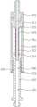
参照图7至图11,如上所述,各缓冲装置200分别具有:呈筒状的第二基座201和滑动杆203。第二基座201和滑动杆203共同形成气路通道221。具体地,缓冲装置200包括:呈筒状的第二基座201、第三气管接头202、滑动杆203以及弹性件204。气路通道221包括沿轴向贯通第二基座201的第六孔部205以及沿轴向贯通滑动杆203的第七孔部206,第六孔部205和第七孔部206连通。第三气管接头202密封地安装到第六孔部205的轴向的一端。第三气管接头202通过气管222并经由第一基座101的第四孔部106和真空发生器121连接。滑动杆203的至少部分容置在第六孔部205内且相对第六孔部205沿轴向可滑动。在滑动杆203沿远离第三气管接头202的方向滑动时,滑动杆203的一部分穿过第六孔部205的轴向的另一端而显露在第二基座201之外。弹性件204以压缩的状态一端抵接滑动杆203且另一端抵接第二基座201。Referring to FIG. 7 to FIG. 11 , as mentioned above, each
在本实施方式的缓冲装置200中,作为第三气管接头202的种类并不特别限定,可列举:直通接头、快插接头的公头或者快插接头的母头等。为了使缓冲装置200的结构整体更加紧凑,同时方便气管222的插拔,优选地,第三气管接头202选择快插接头的公头。In the
作为弹性件204,可以使用例如公知的压缩弹簧。弹性件204只要能够以压缩的状态一端抵接滑动杆203且另一端抵接第二基座201,其安装方式并不特别限定。例如,弹性件204可以设置在第二基座201的外部并套嵌在滑动杆203上,一端抵接滑动杆203且另一端抵接第二基座201。此外,弹性件204也可以容置在第六孔部205内(参照图8至图10),一端抵接滑动杆203且另一端抵接第二基座201。As the
继续参照图8,在一些实施例中,为了连通第三气管接头202和第七孔部206,以使真空吸盘300能够通过滑动杆203以及气管222和真空发生器121连通,第三气管接头202和第七孔部206通过第六孔部205连通。具体而言,例如,滑动杆203沿第六孔部205滑动,第七孔部206的轴向的一端容置在第六孔部205内,由此和第六孔部205连通。第六孔部205的轴向的一端设置有螺纹,第三气管接头202则直接通过该螺纹拧紧到第六孔部205的轴向的一端。为了提高第三气管接头202的安装位置的密封性,第三气管接头202可以通过打密封胶、缠绕密封胶带等方式锁紧到第六孔部205的轴向的一端。由此,能够实现第三气管接头202的安装位置的密封性。Continuing to refer to FIG. 8 , in some embodiments, in order to communicate with the third trachea joint 202 and the
另外,为了实现第六孔部205和滑动杆203之间的密封性,第六孔部205和滑动杆203之间可以设置有第二密封圈207。作为第二密封圈207,列举例如O型橡胶密封圈等。第二密封圈207可以套嵌在滑动杆203上。由此,能够实现第六孔部205的连通第三气管接头202以及滑动杆203的第七孔部206之间的区域的密封性。In addition, in order to achieve sealing between the
继续参照图9,此外,在一些实施例中,为了连通第三气管接头202和第七孔部206,也可以在第三气管接头202的第一安装端208的端部设置有沿轴向延伸的第一延伸部209,第一延伸部209插入第七孔部206内,第一延伸部209和第七孔部206之间设置有第三密封圈210。具体而言,例如,第七孔部206可以是圆孔。第一延伸部209的外周也呈圆柱状。第三密封圈210可以选择例如O型橡胶密封圈等。第三密封圈210可以嵌入在第七孔部206内,也可以套嵌在第一延伸部209中。第一延伸部209沿轴向被贯通并和第三气管接头202连通。由此,能够实现滑动杆203和第三气管接头202直接连通并且相对于第六孔部205被隔绝。通过这种连接方式,能够使第六孔部205仅作为用于对滑动杆203进行导向的孔而使用。由于无需在第六孔部205和滑动杆203之间设置密封圈,因此,能够抑制滑动杆203相对第二基座201的摆动,提高滑动杆203相对第六孔部205的滑动精度。Continuing to refer to FIG. 9 , in addition, in some embodiments, in order to communicate with the third air pipe joint 202 and the
继续参照图10,在一些实施例中,缓冲装置200还可以包括沿轴向被贯通的安装座211,安装座211安装到第六孔部205的轴向的一端,第三气管接头202密封地安装到安装座211。此外,为了提高零件的通用性以及降低缓冲装置200的成本,安装座211的第二安装端部212设置有沿轴向延伸的第二延伸部213,第二延伸部213插入第七孔部206内,第二延伸部213和第七孔部206之间设置有第三密封件214。具体而言,由于第三气管接头202通常是标准件,为了实现滑动杆203的第七孔部206和第三气管接头202直接连通而在第三气管接头202的一端设置第一延伸部209,可能会增加第三气管接头202的加工成本。因此,在本实施例中,通过设置安装座211,并使安装座211的第二延伸部213连通滑动杆203以及第三气管接头202,在能够确保滑动杆203的第七孔部206以及第三气管接头202相对第六孔部205被隔绝的同时,也能够使用市购的第三气管接头202。因此,能够提高第三气管接头202的通用性,降低缓冲装置200的成本。Continuing to refer to FIG. 10 , in some embodiments, the
继续参照图11,在一些实施例中,为了抑制滑动杆203相对第二基座201的转动,从而提高真空吸盘300吸附电子元器件的精度,第六孔部205的内壁上设置有限制部215,滑动杆203的容置在第六孔部205内的部分设置有多边形部216,多边形部216在第六孔部205内沿周向被限制部215限制。具体而言,限制部215可以包括开设在内壁上的多个第二槽部217,多个槽部217槽部217沿第六孔部205的内壁的周向间隔分布,各第二槽部217分别沿第六孔部205的轴向延伸。多边形部216的边角部218分别容置在第二槽部217内,并可沿第二槽部217滑动。通过在第六孔部205的内壁上设置作为限制部215的第二槽部217,并在滑动杆203的容置在第六孔部205内的部分设置多边形部216,多边形部216的转动被限制部215限制,由此,能够抑制滑动杆203相对第二基座201的转动。在对安装到滑动杆203的真空吸盘300要求角度精度的时候,能够提高真空吸盘300的装配和/或工作的角度精度。Continuing to refer to FIG. 11 , in some embodiments, in order to suppress the rotation of the sliding
第六孔部205的横截面的形状并不特别限定,只要能够容置多边形部216,并使多边形部216的边角部218容置在第二槽部217内即可。例如,优选地,第六孔部205的横截面呈圆形状,多个第二槽部217沿第六孔部205的周向均匀分布。更加优选地,多边形部216的横截面可以是正六边形状。第二槽部217则包括六个,沿第六孔部205的周向均匀分布。第六孔部205的直径R1稍小多边形部216即正六边形的直径R2(例如小0.2mm左右)。此外,以第六孔部205为中心相对的两个第二槽部217的最大距离S1则稍大于正六边形的直径(例如大0.2mm左右)。由此,多边形部216能够以边角部218被卡在第二槽部217内的方式,容置在第六孔部205内。The shape of the cross section of the
此外,上面虽然以正六边形状的多边形部216为例进行了说明,但是并不限于此。只要多边形部216的以中心为基准相对的两个边角部218的连线的长度(即直径R2),稍大于第六孔部205的直径R1,且这些多边形部216的边角部218能够容置在第二槽部217,多边形部216的横截面也可以选择例如正方形状或者正五边形状等。In addition, although the regular hexagonal
继续参照图8至图10,在一些实施例中,为了进一步对滑动杆203进行导向且抑制滑动杆203的磨损,第六孔部205的另一端嵌设有衬套219,滑动杆203上设置有圆柱部220,圆柱部220在衬套219内滑动。通过在第六孔部205的一端嵌设衬套219,能够更高精度地对滑动杆203进行导向,抑制滑动杆203相对第二基座201摆动,从而能够提高滑动杆203的滑动精度并抑制滑动杆203的磨损。Continuing to refer to FIG. 8 to FIG. 10 , in some embodiments, in order to further guide the sliding
作为衬套219,例如可以选择PEEK、赛钢等塑料材质加工的衬套,也可以使用无油衬套。此外,衬套219可以通过打胶等方式固定在第六孔部205的轴向的另一端。另外,为了提高滑动杆203相对第二基座201的滑动顺畅度,也可以在第六孔部205和/或衬套219内注入例如高温、低粘度的润滑脂等。As the
[真空吸盘300][Vacuum suction cup 300]
图12是图1的真空吸盘300的仰视图,图13是图12中的D-D处的剖视图。参照图12/13,并辅助参照图1,如上所述,各真空吸盘300分别具有:第三基座301和设置在第三基座301上的吸附件302。具体地,第三基座301的一侧开设有用于和缓冲装置200的气路通道221连通的第八孔部303。第三基座301的另一侧开设有多个第九孔部304,第九孔部304和第八孔部303连通。吸附件302上开设有多个第十孔部305,各第十孔部305分别和各第九孔部304一一相对。FIG. 12 is a bottom view of the
第三基座301可以通过例如铝合金加工而成。第三基座301的形状并不特别限定,例如可以选择正方体形状、长方体形状或者圆柱状等。第八孔部303可以开设在第三基座301的连接到滑动杆203的一侧,第八孔部303通过缓冲装置200的气路通道221、第一基座101的第四孔部106和真空发生器121的吸附端124连接。The
在一些实施例中,吸附件302的材料为发泡海绵材料。具体而言,为了增加吸附件302的柔软性和弹性,吸附件302可以选择发泡海绵材料。作为发泡海绵材料的制作方法,可以列举例如一步发泡法、预聚体发泡法、半预聚体发泡法以及手工发泡法等。In some embodiments, the material of the
此外,作为吸附件302使用的海绵材料,还可以选择例如精品海绵(具有泡孔均匀、拉力性、延伸性等优越性)、高回弹海绵等。作为高回弹海绵,可列举例如橡胶棉等。In addition, as the sponge material used for the adsorbent 302, for example, high-quality sponge (with advantages such as uniform cells, tensile force, and extensibility), high-resilience sponge, etc. can also be selected. As a high resilience sponge, rubber cotton etc. are mentioned, for example.
吸附件302的邵氏硬度A的最小值并不特别限定,可以根据所要吸附的易碎部件的重量适当地选择即可。在一些实施例中,吸附件302的邵氏硬度A为28度以上且32度以下。具体而言,例如,作为吸附件302的海绵材料的邵氏硬度A可以为30度。通过选择邵氏硬度A30度的海绵材料,在保持足够的柔软性以及回弹性的同时,也能够兼顾吸附件302的强度,防止吸附件302变形量过大。由此,能够提高真空吸盘300的可靠性。The minimum value of the Shore hardness A of the
在一些实施例中,吸附件302的厚度(附图中为上下方向的厚度)为12mm以下。即,在本实施方式中,吸附件302的厚度可以是5mm以上且12mm以下。由此,能够使吸附件302的压缩行程在一定的范围之内,防止吸附件302的压缩行程过大导致可靠性降低。In some embodiments, the thickness of the adsorption member 302 (thickness in the vertical direction in the figure) is less than 12 mm. That is, in this embodiment, the thickness of the adsorbent 302 may be not less than 5 mm and not more than 12 mm. Thus, the compression stroke of the
在一些实施例中,吸附件302通过粘接件贴附到第三基座301的下部。例如,吸附件302的上表面贴附有作为粘接件的双面胶。吸附件302通过该双面胶贴附到第三基座301的下部。由此,能够使吸附件302可靠地贴附到第三基座301的下部,且能够便于吸附件302的更换。In some embodiments, the
在上述具体实施方式中所描述的各个具体的技术特征,在不矛盾的情况下,可以通过任何方式进行组合,为了不必要的重复,本实施方式对各种可能的组合方式不另行说明。The various specific technical features described in the above specific implementation manners can be combined in any manner if there is no contradiction. For unnecessary repetition, this embodiment does not separately describe various possible combination manners.
以上实施例仅用于说明本实施方式的技术方案而并非对其进行限制,凡未脱离本实施方式范围的任何修改或者等同替换,均应当涵括在本实施方式的技术方案内。The above embodiments are only used to illustrate the technical solution of this embodiment and not to limit it. Any modification or equivalent replacement that does not depart from the scope of this embodiment shall be included in the technical solution of this embodiment.
Claims (10)
Translated fromChinesePriority Applications (1)
| Application Number | Priority Date | Filing Date | Title |
|---|---|---|---|
| CN202111681377.4ACN116408514B (en) | 2021-12-30 | 2021-12-30 | Vacuum adsorption system for electronic components |
Applications Claiming Priority (1)
| Application Number | Priority Date | Filing Date | Title |
|---|---|---|---|
| CN202111681377.4ACN116408514B (en) | 2021-12-30 | 2021-12-30 | Vacuum adsorption system for electronic components |
Publications (2)
| Publication Number | Publication Date |
|---|---|
| CN116408514Atrue CN116408514A (en) | 2023-07-11 |
| CN116408514B CN116408514B (en) | 2025-06-17 |
Family
ID=87053701
Family Applications (1)
| Application Number | Title | Priority Date | Filing Date |
|---|---|---|---|
| CN202111681377.4AActiveCN116408514B (en) | 2021-12-30 | 2021-12-30 | Vacuum adsorption system for electronic components |
Country Status (1)
| Country | Link |
|---|---|
| CN (1) | CN116408514B (en) |
Citations (5)
| Publication number | Priority date | Publication date | Assignee | Title |
|---|---|---|---|---|
| JPH0342432A (en)* | 1989-04-14 | 1991-02-22 | Maeda Masaki | Adsorbing tool |
| US20100244344A1 (en)* | 2007-12-04 | 2010-09-30 | Sidel Participations | Compact tools with suction cups for handling robot |
| CN210163000U (en)* | 2019-04-15 | 2020-03-20 | 上海正菏智能设备制造股份有限公司 | Low-friction flexible buffer device connected with vacuum chuck |
| CN216729990U (en)* | 2021-12-30 | 2022-06-14 | 深圳鹏斐克科技有限公司 | Vacuum adsorption system for electronic components |
| CN116061223A (en)* | 2021-11-04 | 2023-05-05 | 深圳鹏斐克科技有限公司 | Mounting device for vacuum generator and vacuum adsorption device |
- 2021
- 2021-12-30CNCN202111681377.4Apatent/CN116408514B/enactiveActive
Patent Citations (5)
| Publication number | Priority date | Publication date | Assignee | Title |
|---|---|---|---|---|
| JPH0342432A (en)* | 1989-04-14 | 1991-02-22 | Maeda Masaki | Adsorbing tool |
| US20100244344A1 (en)* | 2007-12-04 | 2010-09-30 | Sidel Participations | Compact tools with suction cups for handling robot |
| CN210163000U (en)* | 2019-04-15 | 2020-03-20 | 上海正菏智能设备制造股份有限公司 | Low-friction flexible buffer device connected with vacuum chuck |
| CN116061223A (en)* | 2021-11-04 | 2023-05-05 | 深圳鹏斐克科技有限公司 | Mounting device for vacuum generator and vacuum adsorption device |
| CN216729990U (en)* | 2021-12-30 | 2022-06-14 | 深圳鹏斐克科技有限公司 | Vacuum adsorption system for electronic components |
Also Published As
| Publication number | Publication date |
|---|---|
| CN116408514B (en) | 2025-06-17 |
Similar Documents
| Publication | Publication Date | Title |
|---|---|---|
| CN113714951B (en) | Vacuum chuck and vacuum adsorption device | |
| KR100921398B1 (en) | Picker of transfer tool and transfer tool with it | |
| CN107186518A (en) | Flexible fast regulating vacuum cup suitable for Machining energetic materials | |
| CN205521462U (en) | Vacuum adsorption platform | |
| CN216266103U (en) | Mounting device for vacuum generator and vacuum adsorption device | |
| CN216729990U (en) | Vacuum adsorption system for electronic components | |
| CN116408514A (en) | Vacuum adsorption system for electronic components | |
| CN210403692U (en) | Bonding head assembly and chip bonding equipment with same | |
| CN116061223B (en) | Vacuum ejector mounting device and vacuum adsorption device | |
| CN218427642U (en) | Wafer thinning device | |
| CN215625254U (en) | Buffer device for vacuum chuck and vacuum chuck assembly | |
| CN105584828B (en) | Adsorption device | |
| CN112476295A (en) | Vacuum adsorption device | |
| CN218110434U (en) | Double-sided adsorption vacuum cup and adsorption device for glass grinding | |
| CN211034358U (en) | Suction nozzle and suction module applying same | |
| CN116081291A (en) | Air source separation type vacuum maintenance turnover mechanism | |
| CN116354109A (en) | Inverter vacuum adsorption device | |
| CN110091192B (en) | Plate combined connection buckle threaded hole machining clamp | |
| CN108857981A (en) | Product positioning device and positioning method | |
| KR20230159600A (en) | stop valve | |
| CN215774115U (en) | Component automatic adsorption feeding mechanism on PCB printed board | |
| CN114976814B (en) | Preformed hole plugging device for narrow space | |
| CN223023253U (en) | Photovoltaic module string repair grabbing device | |
| CN219892933U (en) | L-shaped high-pressure vacuum feed-in assembly | |
| CN210500323U (en) | No trace sucking disc |
Legal Events
| Date | Code | Title | Description |
|---|---|---|---|
| PB01 | Publication | ||
| PB01 | Publication | ||
| SE01 | Entry into force of request for substantive examination | ||
| SE01 | Entry into force of request for substantive examination | ||
| GR01 | Patent grant | ||
| GR01 | Patent grant |