CN116408161A - Microfluidic device and method with improved capture efficiency - Google Patents
Microfluidic device and method with improved capture efficiencyDownload PDFInfo
- Publication number
- CN116408161A CN116408161ACN202111666965.0ACN202111666965ACN116408161ACN 116408161 ACN116408161 ACN 116408161ACN 202111666965 ACN202111666965 ACN 202111666965ACN 116408161 ACN116408161 ACN 116408161A
- Authority
- CN
- China
- Prior art keywords
- channel
- electrode
- microfluidic
- microwells
- microfluidic device
- Prior art date
- Legal status (The legal status is an assumption and is not a legal conclusion. Google has not performed a legal analysis and makes no representation as to the accuracy of the status listed.)
- Pending
Links
Images


Classifications
- B—PERFORMING OPERATIONS; TRANSPORTING
- B01—PHYSICAL OR CHEMICAL PROCESSES OR APPARATUS IN GENERAL
- B01L—CHEMICAL OR PHYSICAL LABORATORY APPARATUS FOR GENERAL USE
- B01L3/00—Containers or dishes for laboratory use, e.g. laboratory glassware; Droppers
- B01L3/50—Containers for the purpose of retaining a material to be analysed, e.g. test tubes
- B01L3/502—Containers for the purpose of retaining a material to be analysed, e.g. test tubes with fluid transport, e.g. in multi-compartment structures
- B01L3/5027—Containers for the purpose of retaining a material to be analysed, e.g. test tubes with fluid transport, e.g. in multi-compartment structures by integrated microfluidic structures, i.e. dimensions of channels and chambers are such that surface tension forces are important, e.g. lab-on-a-chip
- B—PERFORMING OPERATIONS; TRANSPORTING
- B01—PHYSICAL OR CHEMICAL PROCESSES OR APPARATUS IN GENERAL
- B01L—CHEMICAL OR PHYSICAL LABORATORY APPARATUS FOR GENERAL USE
- B01L3/00—Containers or dishes for laboratory use, e.g. laboratory glassware; Droppers
- B—PERFORMING OPERATIONS; TRANSPORTING
- B01—PHYSICAL OR CHEMICAL PROCESSES OR APPARATUS IN GENERAL
- B01L—CHEMICAL OR PHYSICAL LABORATORY APPARATUS FOR GENERAL USE
- B01L3/00—Containers or dishes for laboratory use, e.g. laboratory glassware; Droppers
- B01L3/50—Containers for the purpose of retaining a material to be analysed, e.g. test tubes
- B01L3/502—Containers for the purpose of retaining a material to be analysed, e.g. test tubes with fluid transport, e.g. in multi-compartment structures
- B01L3/5027—Containers for the purpose of retaining a material to be analysed, e.g. test tubes with fluid transport, e.g. in multi-compartment structures by integrated microfluidic structures, i.e. dimensions of channels and chambers are such that surface tension forces are important, e.g. lab-on-a-chip
- B01L3/50273—Containers for the purpose of retaining a material to be analysed, e.g. test tubes with fluid transport, e.g. in multi-compartment structures by integrated microfluidic structures, i.e. dimensions of channels and chambers are such that surface tension forces are important, e.g. lab-on-a-chip characterised by the means or forces applied to move the fluids
- C—CHEMISTRY; METALLURGY
- C12—BIOCHEMISTRY; BEER; SPIRITS; WINE; VINEGAR; MICROBIOLOGY; ENZYMOLOGY; MUTATION OR GENETIC ENGINEERING
- C12M—APPARATUS FOR ENZYMOLOGY OR MICROBIOLOGY; APPARATUS FOR CULTURING MICROORGANISMS FOR PRODUCING BIOMASS, FOR GROWING CELLS OR FOR OBTAINING FERMENTATION OR METABOLIC PRODUCTS, i.e. BIOREACTORS OR FERMENTERS
- C12M1/00—Apparatus for enzymology or microbiology
- C12M1/36—Apparatus for enzymology or microbiology including condition or time responsive control, e.g. automatically controlled fermentors
- C—CHEMISTRY; METALLURGY
- C12—BIOCHEMISTRY; BEER; SPIRITS; WINE; VINEGAR; MICROBIOLOGY; ENZYMOLOGY; MUTATION OR GENETIC ENGINEERING
- C12M—APPARATUS FOR ENZYMOLOGY OR MICROBIOLOGY; APPARATUS FOR CULTURING MICROORGANISMS FOR PRODUCING BIOMASS, FOR GROWING CELLS OR FOR OBTAINING FERMENTATION OR METABOLIC PRODUCTS, i.e. BIOREACTORS OR FERMENTERS
- C12M1/00—Apparatus for enzymology or microbiology
- C12M1/42—Apparatus for the treatment of microorganisms or enzymes with electrical or wave energy, e.g. magnetism, sonic waves
- C—CHEMISTRY; METALLURGY
- C12—BIOCHEMISTRY; BEER; SPIRITS; WINE; VINEGAR; MICROBIOLOGY; ENZYMOLOGY; MUTATION OR GENETIC ENGINEERING
- C12M—APPARATUS FOR ENZYMOLOGY OR MICROBIOLOGY; APPARATUS FOR CULTURING MICROORGANISMS FOR PRODUCING BIOMASS, FOR GROWING CELLS OR FOR OBTAINING FERMENTATION OR METABOLIC PRODUCTS, i.e. BIOREACTORS OR FERMENTERS
- C12M23/00—Constructional details, e.g. recesses, hinges
- C12M23/02—Form or structure of the vessel
- C12M23/16—Microfluidic devices; Capillary tubes
- C—CHEMISTRY; METALLURGY
- C12—BIOCHEMISTRY; BEER; SPIRITS; WINE; VINEGAR; MICROBIOLOGY; ENZYMOLOGY; MUTATION OR GENETIC ENGINEERING
- C12M—APPARATUS FOR ENZYMOLOGY OR MICROBIOLOGY; APPARATUS FOR CULTURING MICROORGANISMS FOR PRODUCING BIOMASS, FOR GROWING CELLS OR FOR OBTAINING FERMENTATION OR METABOLIC PRODUCTS, i.e. BIOREACTORS OR FERMENTERS
- C12M3/00—Tissue, human, animal or plant cell, or virus culture apparatus
- C—CHEMISTRY; METALLURGY
- C12—BIOCHEMISTRY; BEER; SPIRITS; WINE; VINEGAR; MICROBIOLOGY; ENZYMOLOGY; MUTATION OR GENETIC ENGINEERING
- C12M—APPARATUS FOR ENZYMOLOGY OR MICROBIOLOGY; APPARATUS FOR CULTURING MICROORGANISMS FOR PRODUCING BIOMASS, FOR GROWING CELLS OR FOR OBTAINING FERMENTATION OR METABOLIC PRODUCTS, i.e. BIOREACTORS OR FERMENTERS
- C12M35/00—Means for application of stress for stimulating the growth of microorganisms or the generation of fermentation or metabolic products; Means for electroporation or cell fusion
- C12M35/02—Electrical or electromagnetic means, e.g. for electroporation or for cell fusion
- C—CHEMISTRY; METALLURGY
- C12—BIOCHEMISTRY; BEER; SPIRITS; WINE; VINEGAR; MICROBIOLOGY; ENZYMOLOGY; MUTATION OR GENETIC ENGINEERING
- C12M—APPARATUS FOR ENZYMOLOGY OR MICROBIOLOGY; APPARATUS FOR CULTURING MICROORGANISMS FOR PRODUCING BIOMASS, FOR GROWING CELLS OR FOR OBTAINING FERMENTATION OR METABOLIC PRODUCTS, i.e. BIOREACTORS OR FERMENTERS
- C12M41/00—Means for regulation, monitoring, measurement or control, e.g. flow regulation
- C12M41/30—Means for regulation, monitoring, measurement or control, e.g. flow regulation of concentration
- C12M41/36—Means for regulation, monitoring, measurement or control, e.g. flow regulation of concentration of biomass, e.g. colony counters or by turbidity measurements
- C—CHEMISTRY; METALLURGY
- C12—BIOCHEMISTRY; BEER; SPIRITS; WINE; VINEGAR; MICROBIOLOGY; ENZYMOLOGY; MUTATION OR GENETIC ENGINEERING
- C12M—APPARATUS FOR ENZYMOLOGY OR MICROBIOLOGY; APPARATUS FOR CULTURING MICROORGANISMS FOR PRODUCING BIOMASS, FOR GROWING CELLS OR FOR OBTAINING FERMENTATION OR METABOLIC PRODUCTS, i.e. BIOREACTORS OR FERMENTERS
- C12M47/00—Means for after-treatment of the produced biomass or of the fermentation or metabolic products, e.g. storage of biomass
- C12M47/04—Cell isolation or sorting
- C—CHEMISTRY; METALLURGY
- C12—BIOCHEMISTRY; BEER; SPIRITS; WINE; VINEGAR; MICROBIOLOGY; ENZYMOLOGY; MUTATION OR GENETIC ENGINEERING
- C12N—MICROORGANISMS OR ENZYMES; COMPOSITIONS THEREOF; PROPAGATING, PRESERVING, OR MAINTAINING MICROORGANISMS; MUTATION OR GENETIC ENGINEERING; CULTURE MEDIA
- C12N5/00—Undifferentiated human, animal or plant cells, e.g. cell lines; Tissues; Cultivation or maintenance thereof; Culture media therefor
- C12N5/10—Cells modified by introduction of foreign genetic material
- C12N5/12—Fused cells, e.g. hybridomas
- B—PERFORMING OPERATIONS; TRANSPORTING
- B01—PHYSICAL OR CHEMICAL PROCESSES OR APPARATUS IN GENERAL
- B01L—CHEMICAL OR PHYSICAL LABORATORY APPARATUS FOR GENERAL USE
- B01L2200/00—Solutions for specific problems relating to chemical or physical laboratory apparatus
- B01L2200/10—Integrating sample preparation and analysis in single entity, e.g. lab-on-a-chip concept
- B—PERFORMING OPERATIONS; TRANSPORTING
- B01—PHYSICAL OR CHEMICAL PROCESSES OR APPARATUS IN GENERAL
- B01L—CHEMICAL OR PHYSICAL LABORATORY APPARATUS FOR GENERAL USE
- B01L2300/00—Additional constructional details
- B01L2300/08—Geometry, shape and general structure
- B01L2300/0861—Configuration of multiple channels and/or chambers in a single devices
- B—PERFORMING OPERATIONS; TRANSPORTING
- B01—PHYSICAL OR CHEMICAL PROCESSES OR APPARATUS IN GENERAL
- B01L—CHEMICAL OR PHYSICAL LABORATORY APPARATUS FOR GENERAL USE
- B01L2400/00—Moving or stopping fluids
- B01L2400/04—Moving fluids with specific forces or mechanical means
- B01L2400/0403—Moving fluids with specific forces or mechanical means specific forces
- B01L2400/0415—Moving fluids with specific forces or mechanical means specific forces electrical forces, e.g. electrokinetic
- B01L2400/0424—Dielectrophoretic forces
Landscapes
- Health & Medical Sciences (AREA)
- Chemical & Material Sciences (AREA)
- Life Sciences & Earth Sciences (AREA)
- Engineering & Computer Science (AREA)
- Bioinformatics & Cheminformatics (AREA)
- Zoology (AREA)
- Organic Chemistry (AREA)
- Wood Science & Technology (AREA)
- Biotechnology (AREA)
- Genetics & Genomics (AREA)
- Biomedical Technology (AREA)
- General Health & Medical Sciences (AREA)
- General Engineering & Computer Science (AREA)
- Microbiology (AREA)
- Biochemistry (AREA)
- Sustainable Development (AREA)
- Cell Biology (AREA)
- Clinical Laboratory Science (AREA)
- Chemical Kinetics & Catalysis (AREA)
- Analytical Chemistry (AREA)
- Dispersion Chemistry (AREA)
- Medicinal Chemistry (AREA)
- Hematology (AREA)
- Physics & Mathematics (AREA)
- Electromagnetism (AREA)
- Molecular Biology (AREA)
- Virology (AREA)
- Electrostatic Separation (AREA)
- Apparatus Associated With Microorganisms And Enzymes (AREA)
Abstract
Description
Translated fromChinese技术领域technical field
本发明涉及微流体设备,具体涉及可用于单个微物体捕获和分析的微流体设备。本发明还涉及使用该微流体设备捕获单个微物体的方法。The present invention relates to microfluidic devices, and in particular to microfluidic devices that can be used for the capture and analysis of individual microobjects. The invention also relates to methods of capturing single micro-objects using the microfluidic device.
背景技术Background technique
单细胞捕获及分析能够精确地从大量细胞中获取特定单细胞,实现疾病诊断、杂交瘤细胞筛选及药物筛选等多种用途。微流体技术(也称微流控技术)可在单细胞尺度上操控和处理介质中的细胞,实现细胞的捕获、培养、分析、处理、筛选等一系列过程。Single cell capture and analysis can accurately obtain specific single cells from a large number of cells, and realize various purposes such as disease diagnosis, hybridoma cell screening and drug screening. Microfluidic technology (also known as microfluidic technology) can manipulate and process cells in a medium at the single-cell scale to achieve a series of processes such as cell capture, culture, analysis, processing, and screening.
CN 103894248 B公开了一种单细胞分析用微流控芯片,其包括位于微流体通道底部的微孔阵列,微孔仅能容纳单个细胞。微孔内设置一对电极,可用于施加电压使细胞裂解。微孔尺寸为约30微米的立方体,相邻微孔之间的间距为20微米。该技术利用细胞自身重力以及微孔尺寸实现单细胞捕获。然而,利用细胞自身重力实现单细胞捕获需要尽量避免流体流动,通常要使芯片静置一段时间,以避免细胞随流体流动而无法落入微孔,这无疑降低了工作效率。此外,利用细胞自身重力进行单细胞捕获具有随机性,细胞必须位于微孔正上方才能沉降至微孔中,导致在稀有单细胞(例如循环肿瘤细胞)的识别和捕获中该技术不可靠。CN 103894248 B discloses a microfluidic chip for single cell analysis, which includes a microwell array at the bottom of the microfluidic channel, and the microwell can only accommodate a single cell. A pair of electrodes are arranged in the microwell, which can be used to apply voltage to lyse the cells. The microwell size is approximately 30 micron cubes with a 20 micron spacing between adjacent microwells. This technology utilizes the gravity of the cell itself and the size of the micropore to achieve single cell capture. However, using the gravity of the cells to capture single cells requires avoiding fluid flow as much as possible. Usually, the chip must be left to stand for a period of time to prevent cells from falling into the microwells due to fluid flow, which undoubtedly reduces work efficiency. In addition, single-cell capture using the cell's own gravity is random, and cells must be located directly above the microwell to settle into the microwell, making this technique unreliable in the identification and capture of rare single cells (such as circulating tumor cells).
CN 109456874 A公开了一种细胞双向介电泳单细胞操控微流控芯片,其包括具有微阱的微流道,微阱设置在微流道的侧壁上,并靠近可寻址电极。当细胞混合液流经微流控芯片时,施加特定频率的电压驱动可寻址电极,使细胞经受正向介电泳力而被捕获至侧壁上的微阱中,捕获于微阱的目标细胞,在施加另一特定频率的电压驱动可寻址电极后,可使细胞经受负向介电泳而移出微阱。然而,因微阱设置在侧壁上,细胞的捕获完全依赖于单独地激活相应可寻址电极所产生的正、负介电泳力,当要捕获的细胞数量过多时(例如在筛选杂交瘤细胞时),可寻址电极的激活和单个细胞的操作将变得非常复杂和耗时。CN 109456874 A discloses a bidirectional dielectrophoresis single-cell control microfluidic chip, which includes a microfluidic channel with a microwell, and the microwell is arranged on the side wall of the microfluidic channel and is close to an addressable electrode. When the cell mixture flows through the microfluidic chip, a voltage of a specific frequency is applied to drive the addressable electrodes, so that the cells undergo forward dielectrophoretic force and are captured into the microwell on the side wall, and the target cells trapped in the microwell , after applying a voltage of another specific frequency to drive the addressable electrodes, the cells can be subjected to negative dielectrophoresis to move out of the microwell. However, because the microwell is set on the side wall, the capture of cells is completely dependent on the positive and negative dielectrophoretic forces generated by individually activating the corresponding addressable electrodes. When the number of cells to be captured is too large (such as when screening hybridoma cells ), activation of addressable electrodes and manipulation of individual cells would become very complex and time-consuming.
有鉴于此,有必要提供一种改进的微流控设备,其克服现有技术的一个或多个缺陷。In view of this, it is necessary to provide an improved microfluidic device which overcomes one or more defects of the prior art.
发明内容Contents of the invention
本发明的一个方面一种微流体设备,包括:第一电极;能够与第一电极电连接的第二电极;控制器,与所述第二电极电连接,以控制所述第二电极的激活与去激活;设置在第一电极和第二电极之间的至少一个用于容纳液体介质的微流体通道,所述第二电极的激活导致在所述微流体通道的相应位置产生介电泳力;以及复数个微孔,每个所述微孔位于微流体通道的底部并与所述第二电极电连接,其中,每个微孔的尺寸仅能够容纳单个细胞,并且相邻微孔在液体介质流动方向上以第一间距隔开,所述第一间距设置成避免相邻微孔的介电泳力的相互影响。One aspect of the present invention is a microfluidic device comprising: a first electrode; a second electrode capable of being electrically connected to the first electrode; a controller electrically connected to the second electrode to control activation of the second electrode and deactivation; at least one microfluidic channel for containing a liquid medium disposed between the first electrode and the second electrode, the activation of the second electrode causing a dielectrophoretic force at a corresponding position of the microfluidic channel; and a plurality of microwells, each of which is located at the bottom of the microfluidic channel and electrically connected to the second electrode, wherein the size of each microwell can only accommodate a single cell, and adjacent microwells are in liquid medium They are separated by a first distance in the flow direction, and the first distance is set to avoid the mutual influence of the dielectrophoretic force of adjacent microwells.
在一些实施方式中,所述第一电极为平板电极,并且为每个所述微孔所共用。在一些实施方式中,所述第一电极为镀有氧化铟锡(ITO)的导电玻璃。在一些实施方式中,所述第一电极为镀有掺氟氧化锡(FTO)的导电玻璃。In some embodiments, the first electrode is a plate electrode and is shared by each of the microwells. In some embodiments, the first electrode is conductive glass coated with indium tin oxide (ITO). In some embodiments, the first electrode is conductive glass coated with fluorine-doped tin oxide (FTO).
在一些实施方式中,所述第二电极包括复数个点电极,每个点电极对应一个所述微孔。在一些实施方式中,所述点电极是金属电极。In some embodiments, the second electrode includes a plurality of point electrodes, and each point electrode corresponds to one of the micropores. In some embodiments, the point electrodes are metal electrodes.
在一些实施方式中,所述控制器包括位于所述微孔和所述第二电极之间的光电晶体管阵列和激发光束。在一些实施方式中,所述激发光束从第二电极的方向投射至所述光电晶体管阵列。In some embodiments, the controller includes a phototransistor array and an excitation beam positioned between the microwell and the second electrode. In some embodiments, the excitation light beam is projected from the direction of the second electrode to the phototransistor array.
在一些实施方式中,每个所述微流体通道仅包括一组沿该微流体通道内的液体介质流动方向依次排布的微孔。在这些实施方式中,所述微流体通道的宽度为约100至约150微米。In some embodiments, each microfluidic channel only includes a group of micropores arranged sequentially along the flow direction of the liquid medium in the microfluidic channel. In these embodiments, the width of the microfluidic channel is from about 100 to about 150 microns.
在一些实施方式中,每个所述微流体通道包括平行排布的至少两组沿该微流体通道内的液体介质流动方向依次排布的微孔。In some embodiments, each microfluidic channel includes at least two groups of micropores arranged in parallel and sequentially arranged along the flow direction of the liquid medium in the microfluidic channel.
在一些实施方式中,每个所述微流体通道包括第一通道、至少一个与第一通道平行延伸的第二通道以及至少一个连接所述第一通道和第二通道的连接通道,所述连接通道设置成使所述液体介质的流动方向偏转。在一些实施方式中,所述连接通道使所述液体介质的流动方向偏转约180度。In some embodiments, each of the microfluidic channels includes a first channel, at least one second channel extending parallel to the first channel, and at least one connecting channel connecting the first channel and the second channel, the connecting channel Channels are arranged to deflect the direction of flow of the liquid medium. In some embodiments, the connecting channel deflects the flow direction of the liquid medium by about 180 degrees.
在一些实施方式中,每个所述微流体通道包括第一通道、与第一通道平行延伸的第二通道、连接所述第一通道和第二通道的第一连接通道、与第一或第二通道平行延伸的第三通道以及连接所述第二通道和所述第三通道的第二连接通道,所述第一连接通道和所述第二连接通道分别设置成使所述液体介质的流动方向偏转。在一些实施方式中,所述第一连接通道和所述第二连接通道分别使所述液体介质的流动方向偏转约180度。In some embodiments, each of the microfluidic channels includes a first channel, a second channel extending parallel to the first channel, a first connecting channel connecting the first channel and the second channel, and a first or second channel. The third channel extending parallel to the two channels and the second connecting channel connecting the second channel and the third channel, the first connecting channel and the second connecting channel are respectively arranged to make the flow of the liquid medium direction deflection. In some embodiments, the first connecting channel and the second connecting channel respectively deflect the flow direction of the liquid medium by about 180 degrees.
在一些实施方式中,所述微孔为长方体、立方体或半球体的形状。In some embodiments, the micropore is in the shape of a cuboid, a cube or a hemisphere.
在一些实施方式中,所述微孔的开口宽度和深度独立地为约10至约40微米。In some embodiments, the opening width and depth of the microwells are independently about 10 to about 40 microns.
在一些实施方式中,所述第一间距为所述微孔的开口宽度的2至6倍。在一些实施方式中,所述第一间距为约60至约120微米。In some embodiments, the first pitch is 2 to 6 times the opening width of the micropores. In some embodiments, the first pitch is about 60 to about 120 microns.
本发明的另一个方面提供一种捕获单个微物体的方法,包括:(a)提供本发明的任一微流体设备;(b)加入包含微物体的液体介质,使液体介质流动通过至少一部分微孔;(c)在微流体通道中整体施加第一介电泳力,使得至少一部分微物体以单体形式同时进入不同微孔中;(d)识别感兴趣的微孔并在需要时对该微孔单独施加第二介电泳力,以使所述微孔中的单个微物体重新进入微流体通道;以及(e)在需要时获得该重新进入微流体通道的单个微物体。Another aspect of the present invention provides a method of capturing individual microobjects, comprising: (a) providing any of the microfluidic devices of the present invention; (b) adding a liquid medium containing the microobjects, causing the liquid medium to flow through at least a portion of the microfluidic device; (c) apply the first dielectrophoretic force as a whole in the microfluidic channel, so that at least a part of the microobjects enter different microwells simultaneously in the form of monomers; The wells alone apply a second dielectrophoretic force to re-enter the individual micro-objects in the micro-wells into the microfluidic channel; and (e) obtain the re-entry of the individual micro-objects into the microfluidic channel when desired.
在一些实施方式中,所述第一介电泳力是正介电泳力,所述第二介电泳力是负介电泳力。在一些实施方式中,所述正介电泳力通过施加第一频率的交流电实现,所述第一频率为1 KHZ至约100 KHZ。在一些实施方式中,所述负介电泳力通过施加第二频率的交流电实现,所述第二频率为100 kHZ至约10 MHZ。In some embodiments, the first dielectrophoretic force is a positive dielectrophoretic force and the second dielectrophoretic force is a negative dielectrophoretic force. In some embodiments, the positive dielectrophoretic force is achieved by applying an alternating current at a first frequency, and the first frequency is from 1 KHZ to about 100 KHZ. In some embodiments, the negative dielectrophoretic force is achieved by applying an alternating current at a second frequency, the second frequency being from 100 kHz to about 10 MHZ.
在一些实施方式中,所述微物体是活细胞。在一些实施方式中,所述细胞是杂交瘤细胞。在一些实施方式中,所述微物体是微球或磁珠。在一些实施方式中,所述微物体是微球或磁珠的直径为约6至约20微米。In some embodiments, the microbodies are living cells. In some embodiments, the cells are hybridoma cells. In some embodiments, the microobjects are microspheres or magnetic beads. In some embodiments, the microobjects are microspheres or magnetic beads having a diameter of about 6 to about 20 microns.
在一些实施方式中,在步骤(c)中,所述至少一部分微物体通过所述第一介电泳力和重力进入微孔。In some embodiments, in step (c), the at least a part of the micro-objects enters the micropores through the first dielectrophoretic force and gravity.
在一些实施方式中,在步骤(d)中,所述识别感兴趣的微孔是通过将荧光标记的微球加入所述微流体设备以识别具有预期荧光的微孔。In some embodiments, in step (d), the identifying microwells of interest is by adding fluorescently labeled microspheres to the microfluidic device to identify microwells with expected fluorescence.
在一些实施方式中,至少一些所述微物体至少部分地不位于微孔的上方。在一些实施方式中,至少一些所述微物体完全不位于微孔的上方。In some embodiments, at least some of the microobjects are at least partially not located over the microwells. In some embodiments, at least some of the microobjects are not located above the microwells at all.
本发明提供的微流体设备及方法将微孔设置在微流体通道的底部,并使其具有合理的尺寸和间距,配合不同方向的介电泳力,实现单体微物体(例如单细胞)的捕获和收集。本发明在细胞捕获过程中,不依赖于介电泳力对细胞的逐个操控,而是在微流体设备的所有微流体通道内整体施加介电泳力,借助微物体的自身重力和介电泳力同时将所有微物体以单体形式捕获至微孔中,极大地提高了微物体的捕获效率。发明人意外地发现,即使微物体未处于微孔上方也会被捕获至微孔中,因此该微流体设备具有极大的可靠性。In the microfluidic device and method provided by the present invention, the micropores are arranged at the bottom of the microfluidic channel, and make it have a reasonable size and spacing, and cooperate with dielectrophoretic forces in different directions to realize the capture of single microobjects (such as single cells) and collect. In the process of cell capture, the present invention does not rely on the dielectrophoretic force to control the cells one by one, but applies the dielectrophoretic force in all microfluidic channels of the microfluidic device as a whole, and uses the self-gravity and dielectrophoretic force of the micro-object to simultaneously capture All micro-objects are captured into micropores in the form of monomers, which greatly improves the capture efficiency of micro-objects. The inventors have unexpectedly found that the microfluidic device is extremely reliable because microobjects are trapped in the microwells even when they are not over them.
附图说明Description of drawings
本发明将参考附图进行更详细的描述。需要注意的是,图示的方案仅作为本发明实施方式的代表性示例,并且为更清楚地阐释示例性实施方式的细节,附图中的元件并非按实际尺寸等比例绘制,实际元件的数量可以变化,实际元件的相对位置关系与图示基本保持一致,并且某些元件并未示出。在存在多个实施例的情况下,当在之前实施例中已描述的一个或多个特征也可以适用于另一个实施例时,为简要起见,在后的一个或多个实施例不再赘述这些可重复适用的特征,该在后的一个或多个实施例应被理解为已描述了这些可重复适用的特征,除非另有说明。本领域技术人员在阅读本发明后将意识到,在一个图中显示的一个或多个特征可以与在另一个图中的一个或多个特征组合,以构建出一个或多个未在附图中具体示出的替代性实施方式,这些替代性实施方式也构成本发明的一部分。The invention will be described in more detail with reference to the accompanying drawings. It should be noted that the illustrated solution is only a representative example of the embodiment of the present invention, and in order to explain the details of the exemplary embodiment more clearly, the elements in the drawings are not drawn to the same scale as the actual size, and the number of the actual elements It can be changed, and the relative positional relationship of actual components is basically consistent with the illustrations, and some components are not shown. In the case of multiple embodiments, when one or more features described in the previous embodiment can also be applied to another embodiment, for the sake of brevity, the following one or more embodiments will not be repeated. These reapplicable features, the following one or more embodiments should be understood to have described these reapplicable features, unless otherwise stated. Those skilled in the art will appreciate after reading this disclosure that one or more features shown in one figure can be combined with one or more features shown in another figure to create one or more features not shown in the figures. Alternative embodiments are specifically shown in , and these alternative embodiments also form a part of the present invention.
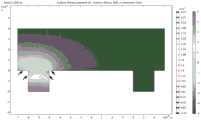
图1示意性显示根据本发明的一个实施例的微流体设备,其中图1A为局部俯视图,图1B为沿B-B的局部剖视图,图1C和1D分别显示了该微流体设备在施加电压时微孔的开口宽度方向和深度方向的电场分布软件模拟结果。Figure 1 schematically shows a microfluidic device according to an embodiment of the present invention, wherein Fig. 1A is a partial top view, and Fig. 1B is a partial cross-sectional view along B-B, and Fig. 1C and 1D respectively show the micropores of the microfluidic device when a voltage is applied The software simulation results of the electric field distribution in the width direction and depth direction of the opening.
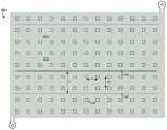
图2示意性显示根据本发明的另一个实施例的微流体设备的局部俯视图。Fig. 2 schematically shows a partial top view of a microfluidic device according to another embodiment of the present invention.
图3示意性显示根据本发明的另一个实施例的微流体设备的局部俯视图,其中图3A显示了其中一个基本形式,图3B显示了其中一个变化形式。Fig. 3 schematically shows a partial top view of a microfluidic device according to another embodiment of the present invention, wherein Fig. 3A shows one of its basic forms, and Fig. 3B shows one of its modified forms.
图4示意性显示根据本发明的另一个实施例的微流体设备的局部剖视图。Fig. 4 schematically shows a partial cross-sectional view of a microfluidic device according to another embodiment of the present invention.
图5显示使用根据本发明的一个微流体设备在实际细胞捕获时的照片。Figure 5 shows photographs of actual cell capture using a microfluidic device according to the present invention.
图6显示根据本发明的一个示例性的方法的流程图。Fig. 6 shows a flowchart of an exemplary method according to the present invention.
具体实施方式Detailed ways
以下结合附图详细描述本发明的示例性实施方式。需要理解的是,本发明的范围不限于所公开的实施方式,本领域技术人员在阅读本发明公开的内容后,基于本发明的启示,可对这些示例性实施方式进行修改和变化,而无需付出创造性劳动,这些修改与变化意在被包含在所附权利要求书概括的范围内。Exemplary embodiments of the present invention will be described in detail below with reference to the accompanying drawings. It should be understood that the scope of the present invention is not limited to the disclosed embodiments, and those skilled in the art can modify and change these exemplary embodiments based on the teachings of the present invention after reading the disclosed content of the present invention without requiring Such modifications and variations are intended to be embraced within the scope outlined by the appended claims as an exercise of inventive effort.
图1A显示根据本发明的一个实施例的微流体设备100的局部俯视图,其移除了部分元件以更清晰地显示微流体设备100的细节。微流体设备100包括流体入口102、流体出口104和多个微流体通道122。流体入口102和流体出口104分别与外界流体连通,包含细胞等微物体的流体(在本文中也称为液体介质,如细胞培养液或生理流体)经由入口102进入微流体设备100,流经多个微流体通122并在其中经受处理和操作(包括光电检测、培养、筛选、移动等),最后从出口104流出,实现微流控芯片的操作程序。微流体通道122通常由高分子材料制成,例如PMMA、PC、PS、PP、PE、PDMS等,或者通过光固化剂制成。在该实施例中,每个微流体通道122由平行延伸的第一侧壁106和第二侧壁108界定,并且均与流体入口102和流体出口104流体连通。FIG. 1A shows a partial top view of a
在每个微流体通道122中设置有复数个微孔120。微孔120位于微流体通道的底部,并且在微流体的流动方向上间隔排布。在该实施例中,每个微流体通道122只包括在横向上对齐的一组微孔120,因而微流体依次流经微孔120,且在同一时刻仅能流经一个微孔120,从而有利于包含细胞等微物体的液体介质在微流体通道中的有序分散。在其他实施例中,所述一组微孔120可在横向上不对齐。A plurality of microwells 120 are provided in each
图1B显示沿图1A的B-B线截取的包含三个微孔120的虚线框处的剖视图。如图所示,该微流体设备100包括基板114(例如玻璃基板)和第一电极112。例如,第一电极112可以是金属电极。合适的金属电极包括金、银、铂、钯、铱、钼等贵金属;铜、锡、锑、铁、钴、镍、铬、钛、锰等金属;或铂钡、钯钡、铱钨铼、铱钡锇等合金。当第一电极是金属电极时,其可以是平板电极,为每个微孔120所共用,也可以是多个点电极,每个点电极对应一个微孔120。作为另一选择,第一电极112可以是形成在基板114上的氧化铟锡(ITO)镀膜,例如ITO玻璃。作为另一选择,第一电极112还可以是形成在基板114上的FTO(SnO2:F)镀膜,例如FTO玻璃。FIG. 1B shows a cross-sectional view taken along the line BB of FIG. 1A at the dotted box including three microwells 120 . As shown, the
该微流体设备100还包括第二电极116。在该实施例中,第二电极116是金属电极,例如金电极或银电极。第二电极116为点电极,每个点电极位于一个微孔120的底部并与微孔120电连接(例如点电极116的至少一部分暴露于微孔120内),并且通过导线连接至共同导体124。在第一电极112和第二电极116之间可施加交流电AC。控制器140与每个第二电极116电连接并单独控制每个第二电极116与交流电AC的连接与断开,从而激活或去激活第二电极116。The
交流电AC的电压可以是方波形、正弦波形或三角波形。交流电AC的峰值电压可以在约1 Vppk与约50 Vppk,例如约1Vppk至约30 Vppk之间,频率在大约1 kHZ与大约10MHZ之间。在本发明中,交流电AC可以提供至少两个工作频率,例如较低的第一工作频率和较高的第二工作频率。第一工作频率例如是1 KHZ至约100 KHZ,例如3 KHZ至约5 KHZ,第二工作频率例如是100 kHZ至约10 MHZ,例如1 MHZ至约3 MHZ。以上关于交流电AC的峰值电压、频率的数值仅为示例,本领域技术人员可以根据实际需要调整而不必限于所列举的数值或其范围。The voltage of the alternating current AC can be a square waveform, a sinusoidal waveform or a triangular waveform. The peak voltage of the alternating current AC may be between about 1 Vppk and about 50 Vppk, such as about 1 Vppk to about 30 Vppk, and the frequency is between about 1 kHz and about 10 MHz. In the present invention, the alternating current AC can provide at least two operating frequencies, such as a lower first operating frequency and a higher second operating frequency. The first working frequency is for example 1 KHZ to about 100 KHZ, for example 3 KHZ to about 5 KHZ, and the second working frequency is for example 100 kHz to about 10 MHZ, for example 1 MHZ to about 3 MHZ. The above numerical values about the peak voltage and frequency of the alternating current AC are only examples, and those skilled in the art can adjust them according to actual needs without being limited to the listed numerical values or their ranges.
微流体通道122介于第一电极112和第二电极116之间。包含细胞118的介质填充在微流体通道122中并可在其中沿箭头A方向流动。微流体通道122的高度d1(即第一电极112至微孔120的开口的间距)通常为20至约80微米。The
微孔120的开口朝向微流体通道122并与微流体通道122流体连通。每个微孔120可具有相等的尺寸。在本发明中,微孔的尺寸被设置成仅能容纳单个细胞。微孔120具有开口宽度w和深度d2。开口宽度w被定义为微孔120在流体在微流体通道122中的流动方向上的长度,深度d2被定义为微孔120由微流体通道122的底部向远离微流体通道122的方向延伸的长度。The opening of the microwell 120 faces and is in fluid communication with the
例如,微孔的开口宽度w可被设置成大于或等于细胞118的直径(在细胞为圆形形态时)或长径(在细胞为椭圆形形态时),例如比细胞118的直径或长径大约5%至约50%,或约5%至约40%,或约5%至约30%,或约5%至约20%,或约5%至约10%,或约10%至约50%,或约10%至约40%,或约10%至约30%,或约10%至约20%,或约20%至约50%,或约20%至约40%,或约30%至约50%,或约40%至约50%。在其他实施例中,微孔的开口宽度w可被设置成小于细胞118的尺寸。细胞118的直径或长径因细胞类型和状态等因素而变化,通常为约20至约30微米。For example, the opening width w of the microwell can be set to be greater than or equal to the diameter (when the cell is in a circular shape) or the major diameter (when the cell is in an elliptical shape), for example, larger than the diameter or major diameter of the cell 118 About 5% to about 50%, or about 5% to about 40%, or about 5% to about 30%, or about 5% to about 20%, or about 5% to about 10%, or about 10% to about 50%, or about 10% to about 40%, or about 10% to about 30%, or about 10% to about 20%, or about 20% to about 50%, or about 20% to about 40%, or about 30% to about 50%, or about 40% to about 50%. In other embodiments, the opening width w of the microwell may be set to be smaller than the size of the cell 118 . The diameter or major axis of cells 118 varies depending on cell type and state, etc., and is typically about 20 to about 30 microns.
在该实施例中,微孔120的开口宽度w和深度d1独立地为约10至约40微米。微孔120的开口宽度w和深度d1可以相等或不相等。例如,微孔120的开口宽度w和深度d1分别为约10至约40微米,或约10至约30微米,或约15至约25微米,或约15至约40微米,或约15至约35微米,或约15至约30微米,或约15至约25微米,或约20至约40微米,或约20至约30微米,或约30至约40微米,或约20微米。在该实施例中,微孔120的开口宽度w和深度d1均为20微米。In this embodiment, the opening width w and depth d1 of microwells 120 are independently about 10 to about 40 microns. The opening width w and depth d1 of the microholes 120 may be equal or unequal. For example, the opening width w and depth d1 of micropore 120 are respectively about 10 to about 40 microns, or about 10 to about 30 microns, or about 15 to about 25 microns, or about 15 to about 40 microns, or about 15 to about 35 microns, or about 15 to about 30 microns, or about 15 to about 25 microns, or about 20 to about 40 microns, or about 20 to about 30 microns, or about 30 to about 40 microns, or about 20 microns. In this embodiment, the opening width w and the depth d1 of the microhole 120 are both 20 micrometers.
微孔120可以设置在衬底130中。衬底130可由与形成微流体通道122的侧壁106和108的材料相同的材料形成,例如PMMA、PC、PS、PP、PE、PDMS等高分子材料或光固化材料。The microwells 120 may be disposed in the
在每个微流体通道122中,相邻微孔120在横向上以距离s间隔开(参考图1A)。距离s的设置,一方面使得微孔不至于太密集而无法形成非均匀的电场(继而无法形成介电泳力),另一方面避免相邻微孔120的介电泳力的相互影响。在该实施例中,距离s的大小为微孔120的开口宽度的约2至约6倍,例如约3至5倍,例如约4倍。例如,距离s可以是约40至约120微米,例如约60至约100微米,或约80微米。在该实施例中,距离s为约80微米。In each
微流体通道122具有宽度m,即第一侧壁106与第二侧壁108的间距。本发明预期,宽度m的大小对于实现本发明的目的不具有实质性影响。优选地,宽度m大于微孔120的开口宽度w。宽度m的设置可以考虑第一侧壁106和第二侧壁108的厚度,以使得微孔120与相邻微流体通道122中的相邻微孔120在纵向上的间距大于或等于距离s。在该实施例中,宽度m可以为约100至约150微米,例如约110至约130微米,例如约120微米。在该实施例中,宽度m为约120微米。The
微孔120可具有任何合适的形状。本发明预期,微孔120的形状对于实现本发明的目的不具有实质性影响。合适的形状包括但不限于长方体、立方体或半球体。本发明预期微孔120也可以是其他规则或不规则的形状。在该实施例中,微孔120的形状为立方体。Microwells 120 may have any suitable shape. The present invention contemplates that the shape of micropores 120 has no substantial effect on achieving the objectives of the present invention. Suitable shapes include, but are not limited to, cuboids, cubes, or hemispheres. The present invention contemplates that the pores 120 may also be of other regular or irregular shapes. In this embodiment, the shape of the microhole 120 is a cube.
图1C和1D分别显示了该实施例提供的微流体设备100在施加电压时微孔120的开口宽度方向和深度方向的电场分布软件模拟结果。使用软件COMSOL 5.5,模拟条件设定如下:交流电压10 Vppk,频率5 KHZ。如图1C和1D所示,在施加电压后,微孔底部的电压最高,并朝着微孔开口方向逐渐减弱。在电场分布方面,在开口宽度方向上(图1C),电场在靠近微孔的开口的两侧(箭头所示)处最强,并随着位置远离开口而宽度方向上逐渐减弱;在开口深度方向上(图1D),电场在开口以及开口两侧(如箭头所示)最强,并随着位置远离开口而在深度方向上逐渐减弱。软件模拟结果显示,当施加低频电压(对应产生正介电泳的吸力)时,电场在微孔的开口及其周围最强,因而有利于将开口处以及开口周围的微物体操控至微孔内。1C and 1D respectively show the software simulation results of the electric field distribution in the width direction and the depth direction of the opening of the micropore 120 when the voltage is applied to the
以下描述该实施例的工作流程。The workflow of this embodiment is described below.
为以单体形式捕获微物体(如细胞118,例如是杂交瘤细胞),在通过流体入口102加入包含细胞118的液体介质后,液体介质流动通过每个微流体通道122,细胞118随之分散在微流体通道122中。发明人发现,在液体介质流动状态下,即使微孔120位于微流体通道122底部,细胞118并不会因自身重力而自然落入微孔120中。保持液体介质以最小的速度流动或使其停止流动,此时一部分细胞118位于微孔120上方(例如细胞118a),而另一部分细胞118至少部分地不在微孔120上方(例如细胞118c)或完全不在微孔120上方(例如虚线显示的细胞118b)。在第一电极112和第二电极116之间施加较低的第一频率(例如3 KHZ)交流电AC,控制器140控制所有第二电极116处于激活状态(即与共同导体124均导通并电连接至第一电极112)。To capture microobjects (such as cells 118, such as hybridoma cells) in monomeric form, after adding a liquid medium containing cells 118 through
得益于每个微孔120适当的大小和间隔,在每个微孔120处都形成非均匀的电场128,因而产生正介电泳力(吸力),在细胞118自身的重力和介电泳吸力的作用下,细胞118a和118c得以被捕获在微孔120a和120c中。发明人惊讶地发现,即使完全不在微孔120b的上方的细胞118b也可以被捕获到微孔120b处。值得注意的是,在该实施例中,第一电极112是平板电极,第二电极116被完全导通,因而同时在整个微流体通道中施加了非均匀电场,介电泳力同时存在于整个微流体通道中,亦即只要施加一次低频电压并导通所有电极,通道中的所有细胞118均同时能够被捕获在单独微孔120中,这显著提高了单细胞的捕获效率。Thanks to the appropriate size and spacing of each microwell 120, a non-uniform
在细胞118被捕获至微孔120后,可经由流体入口102向微流体设备100加入包含一种或多种荧光标记的微球的介质。这些荧光标记的微球表面可修饰有探测细胞118分泌物(例如抗体分子)的探针(例如标记了荧光信号的抗该抗体分子的抗体)。通过检测微孔120内的荧光信号,可以识别含有感兴趣的细胞118的微孔120。After cells 118 are captured into microwells 120 , media comprising one or more fluorescently labeled microspheres can be added to
在识别感兴趣的微孔120后,如果需要获得该微孔内的细胞118,在第一电极112和该微孔120对应的第二电极116(例如通过控制器140选择)之间施加较高的第二频率(例如3MHZ)交流电AC,从而在该微孔120处形成非均匀的电场,产生负介电泳力(斥力),以将微孔120内的细胞118推出微孔120进入微流体通道122中。After identifying the microwell 120 of interest, if it is necessary to obtain the cells 118 in the microwell, a high The second frequency (for example, 3MHZ) alternating current AC, thereby forming a non-uniform electric field at the microwell 120, generating negative dielectrophoretic force (repulsion), so as to push the cells 118 in the microwell 120 out of the microwell 120 into the
随后,可经由流体入口102向微流体设备100加入细胞培养液等介质,使得被推入微流体通道122中的单个细胞随细胞培养液经流体出口104流出并被收集,而未经介电泳力被推入微流体通道122的细胞仍位于微孔120内,不会随细胞培养液的流动而逃逸。收集的单个细胞可在体外克隆,而生产所期望的抗体分子。Subsequently, media such as cell culture fluid can be added to the
以上所述的工作流程仅为该实施例提供的微流体设备100的一个示例性应用场景,本领域技术人员可以预期,该微流体设备100的应用不限于示例的应用,而可适用于其他本领域技术人员已知的用途,包括但不限于核酸适配体的筛选、稀有细胞的捕获和检测、生殖细胞的捕获和融合(人工授精)等。The workflow described above is only an exemplary application scenario of the
图2显示了根据本发明的另一个实施例的微流体设备200的局部俯视图,其显示了微流体通道222和微孔220的排布。在该实施例中,每个微流体通道222由第一侧壁206和平行延伸的第二侧壁208界定。每个微流体通道222包括平行排布的至少两组沿该微流体通道内的液体介质流动方向依次排布的微孔220。在同一个微流体通道222内,每个微孔220在横向上以间距s1隔开,在纵向上以间距s2隔开。间距s1和s2可以相等或不等,并且独立地与图1所示的实施例中的间距s具有相同的数值范围。第一侧壁206和第二侧壁208的间距m’可以是图1所示实施例中的宽度m的约2倍。类似地,间距m’的设置可以考虑第一侧壁206和第二侧壁208的厚度,以使得微孔220与相邻微流体通道222中的相邻微孔220在纵向上的间距大于或等于距离s2。FIG. 2 shows a partial top view of a
在其他实施例中,每个微流体通道222的间距m’可以更大从而可以容纳三个、四个或更多个平行组的微孔220,条件是保持微孔220之间以距离s间隔开。在这些实施例中,液体介质进入微流体设备中,在同一微流体通道中,介质可以同时流经不止一个微孔。In other embodiments, the pitch m' of each microfluidic channel 222 can be larger to accommodate three, four or more parallel sets of
图3A显示根据本发明的另一个实施例的微流体设备300的局部俯视图。微流体设备300包括复数个微流体通道322(例如5个,如322a、322b、322c、322d和322e所示)。流体可从入口302进入微流体设备300,并作为各微流体通道322的共同流体来源,并行地流经各微流体通道322,最终从出口304流出。每个微流体通道322包括横向延伸的第一通道324、横向延伸的第二通道326、横向延伸的第三通道328、连接第一通道324和第二通道326的第一连接通道325以及连接第二通道326和第三通道328的第二连接通道327。第一通道324、第一连接通道325、第二通道326、第二连接通道327以及第三通道328流体连通,并且在流体流动方向上顺次连接。第一、第二和第三通道323、326、328各自可由第一侧壁306和第二侧壁308界定,并且分别只包括在横向上的一组微孔320,因而微流体依次流经微孔320,且在同一时刻仅能流经一个微孔320。FIG. 3A shows a partial top view of a
在该实施例中,微孔320显示为具有圆形的截面,因而其形状可以是例如半球形。在各个微流体通道322中,微孔320分布在第一通道324、第二通道326和第三通道328中,并位于其底部,微孔的大小和间距与图1所示的实施例的微孔120类似,不再赘述。第一连接通道325和第二连接通道327起连接横向延伸的通道的作用,并使流体的流动方向发生偏转(例如180度偏转)。第一连接通道325和第二连接通道327通常可为圆弧状,以提供平滑的流动路径。在其他实施例中,在第一连接通道325和第二连接通道327中也可以设置微孔320。In this embodiment, the
在该实施例提供的微流体设备300中,各个微流体通道322具有均等的接收流体的机会,并且微流体通道具有更长的沿流体流动方向的延伸,因而能够使进入微流体设备300内的流体以及其中包含的微物体(如细胞或微球)在整个设备内更加均匀地分散。In the
图3B显示了微流体设备300的一个变化形式的局部俯视图。该微流体设备300的变体形式包括两个图3A所示的微流体通道的重复单元,因而提供了更大的容量和分析能力。流体从入口302进入微流体设备后,沿着相反方向分别并行地进入各个微流体通道,并从出口304流出。在其他实施例中,流体也可以从出口304处流入微流体设备,流经各个微流体通道后,从入口302处流出。FIG. 3B shows a partial top view of one variation of a
本领域技术人员可以预期到微流体设备300的其他变化形式。例如,微流体设备300可仅包括横向延伸的第一通道324和横向延伸的第二通道326以及第一连接通道325,而不包括第二连接通道327以及第三通道328。或者,微流体设备300可包括更多个(例如三个、四个、五个或更多)的图3A或3B所示的重复单元。或者,第一、第二、第三通道324、326和328各自独立地可包含如图2所示的多组横向上延伸的微孔320。Other variations of
图4显示根据本发明的另一个实施例的微流体设备400的局部剖视图。在该实施例中,微流体设备400包括设置在基板414上的第一电极412,与第一电极412电连接的第二电极416,设置在第二电极416上的光电晶体管阵列426,设置在光电晶体管阵列426上的微孔420,以及微流体通道422,微孔420设置在微流体通道422的底部并与其流体连通。在该实施例中,图1所示的微流体设备100的控制器140具体化为光电晶体管阵列426,其可以在激发光束452的投射下,在曝光区域导通第一电极412和第二电极416,从而在该位置形成非均匀电场,产生介电泳力。激发光束452可以是图案化的光束,从而可以更方便地操控细胞418。光束452可以从第一电极412方向或第二电极416方向投射至光电晶体管阵列426,优选从第二电极416方向投射,以避免细胞418部分地遮挡光束452而弱化其光电效应,导致介电泳力(特别是细胞418处于微孔420中待推出时所需的负介电泳力)减小。合适的光电晶体管阵列426在本领域是已知的,例如参见US 7,956,339 B2或CN 107223074 B。FIG. 4 shows a partial cross-sectional view of a
图5显示了使用根据本发明的一个微流体设备300的变化形式在实际细胞捕获时的照片。该照片显示在未施加电压时(0秒)以及施加电压后(10、20、30、40秒)后的细胞捕获过程。如图所示,在0秒时,细胞(图示右侧箭头所示)位于微孔(图示左侧箭头所示)的约20微米处。施加低频电压(正介电泳力)后,细胞开始逐渐向所示微孔移动,并最终在第40秒,完全移入微孔内而与微孔影像重叠。Figure 5 shows photographs of actual cell capture using a variant of a
图6显示根据本发明的一个示例性的捕获单体微物体的方法600的流程图。该方法开始于步骤602,其提供如本发明所述的任一微流体设备,该微流体设备包含微流体通道,微流体通道的底部设置有复数个仅能容纳单个微物体的微孔,所述微孔以预定距离间隔开。FIG. 6 shows a flowchart of an
在步骤604中,向所述微流体设备中加入含有微物体(例如杂交瘤细胞)的液体介质,使液体介质流动通过至少一部分微孔。优选地,液体介质流动通过整个微流体通道从而流动通过所有微孔。In
随后,方法进行步骤606,在微流体通道中整体施加第一介电泳力,使得至少一部分微物体以单体形式进入不同微孔中。例如,至少一部分微物体通过第一介电泳力和重力进入微孔。第一介电泳力可以是正介电泳力,从而产生吸力,例如可以通过施加频率为1KHZ至约100 KHZ,例如3 KHZ至约5 KHZ的交流电来实现。Subsequently, the method proceeds to step 606, applying a first dielectrophoretic force in the microfluidic channel as a whole, so that at least a part of the micro objects enter different microwells in the form of monomers. For example, at least a portion of the micro-objects enters the micro-wells via a first dielectrophoretic force and gravity. The first dielectrophoretic force may be a positive dielectrophoretic force, thereby generating a suction force, for example, by applying an alternating current with a frequency of 1 KHZ to about 100 KHZ, for example, 3 KHZ to about 5 KHZ.
在步骤608中,识别感兴趣的微孔并在需要时对该微孔单独施加第二介电泳力,以使微孔中的单个微物体重新进入微流体通道。例如,通过将荧光标记的微球加入所述微流体设备以识别具有预期荧光的微孔来识别感兴趣的微孔。例如,第二介电泳力可以是负介电泳力,从而产生斥力,例如可以通过施加频率为100 kHZ至约10 MHZ,例如1 MHZ至约3MHZ的交流电来实现。In
最后,在步骤610中,例如通过加入细胞培养液等介质而从微流体设备的流体出口收集该单个微物体。其中,未经介电泳力被推入微流体通道的细胞仍位于微孔内,不会随细胞培养液的流动而离开微孔。Finally, in
以上所述皆为本发明实施方式的代表性示例,且仅为说明性目的提供。本发明预期在一个实施方式中使用的一个或多个技术特征,在不违背实施方式的目的的情况下,可以添加至另一个实施方式中,以形成改进或替代的实施方式。同理,在一个实施方式中使用的一个或多个技术特征,在不违背实施方式的目的的情况下可以被省略或替代,以形成替代的或简化的实施方式。此外,在一个实施方式中使用的一个或多个技术特征,在不违背实施方式的目的的情况下,可与另一个实施方式中的一个或多个技术特征组合,以形成改进的或替代的实施方式。本发明意在包括所有以上改进的、替代的、简化的技术方案。The foregoing are all representative examples of embodiments of the present invention, and are provided for illustrative purposes only. The present invention contemplates that one or more technical features used in one embodiment can be added to another embodiment to form an improved or alternative embodiment without violating the purpose of the embodiment. Similarly, one or more technical features used in one embodiment may be omitted or replaced without violating the purpose of the embodiment, so as to form an alternative or simplified embodiment. In addition, one or more technical features used in one embodiment can be combined with one or more technical features in another embodiment to form an improved or alternative implementation. The present invention intends to include all the above improved, replaced and simplified technical solutions.
Claims (22)
Priority Applications (2)
| Application Number | Priority Date | Filing Date | Title |
|---|---|---|---|
| CN202111666965.0ACN116408161A (en) | 2021-12-31 | 2021-12-31 | Microfluidic device and method with improved capture efficiency |
| PCT/CN2022/143880WO2023125926A1 (en) | 2021-12-31 | 2022-12-30 | Microfluidic device with improved capture efficiency, and method |
Applications Claiming Priority (1)
| Application Number | Priority Date | Filing Date | Title |
|---|---|---|---|
| CN202111666965.0ACN116408161A (en) | 2021-12-31 | 2021-12-31 | Microfluidic device and method with improved capture efficiency |
Publications (1)
| Publication Number | Publication Date |
|---|---|
| CN116408161Atrue CN116408161A (en) | 2023-07-11 |
Family
ID=86998120
Family Applications (1)
| Application Number | Title | Priority Date | Filing Date |
|---|---|---|---|
| CN202111666965.0APendingCN116408161A (en) | 2021-12-31 | 2021-12-31 | Microfluidic device and method with improved capture efficiency |
Country Status (2)
| Country | Link |
|---|---|
| CN (1) | CN116408161A (en) |
| WO (1) | WO2023125926A1 (en) |
Cited By (1)
| Publication number | Priority date | Publication date | Assignee | Title |
|---|---|---|---|---|
| CN116727006A (en)* | 2022-03-04 | 2023-09-12 | 彩科(苏州)生物科技有限公司 | High-throughput dielectrophoresis devices and microfluidic devices with optimized electrode arrangement and wiring |
Citations (9)
| Publication number | Priority date | Publication date | Assignee | Title |
|---|---|---|---|---|
| CN101267889A (en)* | 2005-07-19 | 2008-09-17 | 硅生物系统股份公司 | Method and device for manipulating and/or detecting particles |
| CN101484245A (en)* | 2006-04-12 | 2009-07-15 | 硅生物系统股份公司 | Methods and apparatus for the selection and/or processing ofparticles, in particular for the selective and/or optimised lysis of cells |
| US20120156675A1 (en)* | 2009-06-09 | 2012-06-21 | Oxford Gene Technology Ip Limited | Picowell capture devices for analysing single cells or other particles |
| CN104870093A (en)* | 2012-12-05 | 2015-08-26 | 卡钳生命科学股份有限公司 | Manipulation of objects in microfluidic devices using external electrodes |
| CN106497786A (en)* | 2016-11-18 | 2017-03-15 | 清华大学深圳研究生院 | A kind of for unicellular seizure and culture micro-fluidic chip |
| CN107118938A (en)* | 2017-04-07 | 2017-09-01 | 中北大学 | The unicellular arrangement of fluid enhancing dielectrophoresis and control chip and preparation method thereof |
| CN108472649A (en)* | 2015-10-27 | 2018-08-31 | 伯克利之光生命科技公司 | Microfluidic devices with optimized electrowetting surfaces and related systems and methods |
| CN108977343A (en)* | 2018-09-04 | 2018-12-11 | 哈尔滨工业大学 | The micro-fluidic chip separated for cell with capture based on dielectrophoresis principle |
| CN113348036A (en)* | 2018-11-19 | 2021-09-03 | 伯克利之光生命科技公司 | Microfluidic device with programmable switching elements |
Family Cites Families (3)
| Publication number | Priority date | Publication date | Assignee | Title |
|---|---|---|---|---|
| DE102010003001B4 (en)* | 2010-03-18 | 2024-02-08 | Robert Bosch Gmbh | Microfluidic dielectrophoresis system |
| CN103894248B (en)* | 2014-04-09 | 2015-09-16 | 国家纳米科学中心 | A kind of single cell analysis micro-fluidic chip and system and single cell analysis method |
| CN109456874B (en)* | 2018-10-16 | 2021-03-09 | 上海交通大学 | A cell two-dimensional dielectrophoresis single-cell manipulation microfluidic chip |
- 2021
- 2021-12-31CNCN202111666965.0Apatent/CN116408161A/enactivePending
- 2022
- 2022-12-30WOPCT/CN2022/143880patent/WO2023125926A1/ennot_activeCeased
Patent Citations (9)
| Publication number | Priority date | Publication date | Assignee | Title |
|---|---|---|---|---|
| CN101267889A (en)* | 2005-07-19 | 2008-09-17 | 硅生物系统股份公司 | Method and device for manipulating and/or detecting particles |
| CN101484245A (en)* | 2006-04-12 | 2009-07-15 | 硅生物系统股份公司 | Methods and apparatus for the selection and/or processing ofparticles, in particular for the selective and/or optimised lysis of cells |
| US20120156675A1 (en)* | 2009-06-09 | 2012-06-21 | Oxford Gene Technology Ip Limited | Picowell capture devices for analysing single cells or other particles |
| CN104870093A (en)* | 2012-12-05 | 2015-08-26 | 卡钳生命科学股份有限公司 | Manipulation of objects in microfluidic devices using external electrodes |
| CN108472649A (en)* | 2015-10-27 | 2018-08-31 | 伯克利之光生命科技公司 | Microfluidic devices with optimized electrowetting surfaces and related systems and methods |
| CN106497786A (en)* | 2016-11-18 | 2017-03-15 | 清华大学深圳研究生院 | A kind of for unicellular seizure and culture micro-fluidic chip |
| CN107118938A (en)* | 2017-04-07 | 2017-09-01 | 中北大学 | The unicellular arrangement of fluid enhancing dielectrophoresis and control chip and preparation method thereof |
| CN108977343A (en)* | 2018-09-04 | 2018-12-11 | 哈尔滨工业大学 | The micro-fluidic chip separated for cell with capture based on dielectrophoresis principle |
| CN113348036A (en)* | 2018-11-19 | 2021-09-03 | 伯克利之光生命科技公司 | Microfluidic device with programmable switching elements |
Cited By (1)
| Publication number | Priority date | Publication date | Assignee | Title |
|---|---|---|---|---|
| CN116727006A (en)* | 2022-03-04 | 2023-09-12 | 彩科(苏州)生物科技有限公司 | High-throughput dielectrophoresis devices and microfluidic devices with optimized electrode arrangement and wiring |
Also Published As
| Publication number | Publication date |
|---|---|
| WO2023125926A1 (en) | 2023-07-06 |
Similar Documents
| Publication | Publication Date | Title |
|---|---|---|
| Zhang et al. | Tunable particle separation in a hybrid dielectrophoresis (DEP)-inertial microfluidic device | |
| US8932447B2 (en) | Ex-vivo multi-dimensional system for the separation and isolation of cells, vesicles, nanoparticles, and biomarkers | |
| US6958245B2 (en) | Array cytometry | |
| US7056746B2 (en) | Array cytometry | |
| US20120058504A1 (en) | Methods and apparatus for dielectrophoretic shuttling and measurement of single cells or other particles in microfluidic chips | |
| JP2001500961A (en) | Light-controlled electrokinetic assembly of particle-proximal surfaces | |
| US9873129B1 (en) | Multi-planar microelectrode array device and methods of making and using same | |
| WO2001020593A9 (en) | System and method for programmable illumination pattern generation | |
| CN111108365A (en) | Assay system and method for processing sample entities | |
| CN113265327B (en) | A kind of AC-dielectrophoresis microalgae multi-stage sorting device and method based on algal lipid content | |
| WO2023125926A1 (en) | Microfluidic device with improved capture efficiency, and method | |
| JP6755178B2 (en) | Particle manipulation device and particle classification method using the device | |
| US11712693B2 (en) | Integrated selective capture, sequestration, fluidic isolation, electrical lysis and analysis of single cells | |
| Wang et al. | Microfluidic-based electrically driven particle manipulation techniques for biomedical applications | |
| Medoro et al. | Lab on a chip for live-cell manipulation | |
| TWI352266B (en) | Particles-lifting device and optical tweezers usin | |
| CN107974400A (en) | It is a kind of to couple dielectrophoresis and the micro-current controlled cell being spatially separating sorting chip and method | |
| CN117025534A (en) | Method for separating cancer cells with different drug resistance degrees based on photoinduced dielectrophoresis microfluidic technology | |
| US11850595B2 (en) | Nanofluidic flow cell and method of loading same | |
| Viefhues | Analytics in microfluidic systems | |
| TWI693401B (en) | Method for screening, isolating and purifying analytes | |
| CN117844757A (en) | Method for screening cells with different drug resistance using light-induced dielectrophoresis virtual channel technology | |
| CN119894199A (en) | Micro LED fluid assembling method based on Micro-flow control and dielectrophoresis | |
| Wu | Advances of LOC-based particle manipulation by AC electrical fields | |
| JP2006087376A (en) | Cell trap device |
Legal Events
| Date | Code | Title | Description |
|---|---|---|---|
| PB01 | Publication | ||
| PB01 | Publication | ||
| SE01 | Entry into force of request for substantive examination | ||
| SE01 | Entry into force of request for substantive examination |