CN116407225A - a cutting device - Google Patents
a cutting deviceDownload PDFInfo
- Publication number
- CN116407225A CN116407225ACN202111678798.1ACN202111678798ACN116407225ACN 116407225 ACN116407225 ACN 116407225ACN 202111678798 ACN202111678798 ACN 202111678798ACN 116407225 ACN116407225 ACN 116407225A
- Authority
- CN
- China
- Prior art keywords
- catheter
- shaft
- clamping
- assembly
- handle body
- Prior art date
- Legal status (The legal status is an assumption and is not a legal conclusion. Google has not performed a legal analysis and makes no representation as to the accuracy of the status listed.)
- Pending
Links
Images


Classifications
- A—HUMAN NECESSITIES
- A61—MEDICAL OR VETERINARY SCIENCE; HYGIENE
- A61B—DIAGNOSIS; SURGERY; IDENTIFICATION
- A61B17/00—Surgical instruments, devices or methods
- A61B17/32—Surgical cutting instruments
- A61B17/3205—Excision instruments
- A61B17/3207—Atherectomy devices working by cutting or abrading; Similar devices specially adapted for non-vascular obstructions
- A61B17/320758—Atherectomy devices working by cutting or abrading; Similar devices specially adapted for non-vascular obstructions with a rotating cutting instrument, e.g. motor driven
- A—HUMAN NECESSITIES
- A61—MEDICAL OR VETERINARY SCIENCE; HYGIENE
- A61B—DIAGNOSIS; SURGERY; IDENTIFICATION
- A61B17/00—Surgical instruments, devices or methods
- A61B17/32—Surgical cutting instruments
- A61B17/3205—Excision instruments
- A61B17/3207—Atherectomy devices working by cutting or abrading; Similar devices specially adapted for non-vascular obstructions
- A61B2017/320741—Atherectomy devices working by cutting or abrading; Similar devices specially adapted for non-vascular obstructions for stripping the intima or the internal plaque from a blood vessel, e.g. for endarterectomy
Landscapes
- Health & Medical Sciences (AREA)
- Surgery (AREA)
- Life Sciences & Earth Sciences (AREA)
- Biomedical Technology (AREA)
- Nuclear Medicine, Radiotherapy & Molecular Imaging (AREA)
- Engineering & Computer Science (AREA)
- Vascular Medicine (AREA)
- Heart & Thoracic Surgery (AREA)
- Medical Informatics (AREA)
- Molecular Biology (AREA)
- Animal Behavior & Ethology (AREA)
- General Health & Medical Sciences (AREA)
- Public Health (AREA)
- Veterinary Medicine (AREA)
- Surgical Instruments (AREA)
Abstract
Description
Translated fromChinese技术领域technical field
本发明属于医疗器械技术领域,具体涉及一种切除装置。The invention belongs to the technical field of medical instruments, and in particular relates to a resection device.
背景技术Background technique
随着中国人口老龄化程度的日益加深及饮食结构的改变,血管 病变发病率急剧上升。外周动脉疾病是血管病变的其中之一,外周 动脉疾病的主要病因是动脉粥样硬化,常表现为四肢、腹腔动脉、 颈动脉和肾动脉等缺血性改变,治疗方法主要包括以药物治疗为主 的基础治疗,包括经典的外科旁路术为代表的开放式外科手术治疗 和新近发展的血管腔内介入治疗。With the deepening of China's aging population and changes in dietary structure, the incidence of vascular disease has risen sharply. Peripheral arterial disease is one of the vascular lesions. The main cause of peripheral arterial disease is atherosclerosis, which often manifests as ischemic changes in the extremities, celiac artery, carotid artery, and renal artery. The treatment methods mainly include drug therapy. The main basic treatment includes open surgical treatment represented by classic surgical bypass and newly developed endovascular interventional treatment.
虽然外科旁路术具有相对优越的长期通畅率,但是血管腔内介 入治疗技术以其微创、安全有效、可重复性的优势逐步被临床医生 和患者所接受。其中,外周斑块旋切术主要针对股、腘及膝下动脉 狭窄或闭塞。Although surgical bypass has a relatively superior long-term patency rate, endovascular interventional therapy is gradually accepted by clinicians and patients due to its advantages of minimal invasiveness, safety, effectiveness, and repeatability. Among them, peripheral atherectomy is mainly aimed at femoral, popliteal and subgenital artery stenosis or occlusion.
在实际临床应用中,医生可以根据患者外周血管病变的情况, 选择旋切术进行处理,在旋切的过程中,由于斑块在不断的沿着导 管往手柄方向排出,难免会遇到斑块或者血栓卡在导管上的情况。 一旦斑块或者血栓卡在导管内部,则会影响手术效率。另外,当导管内斑块或者血栓无法及时排出,刀头切除的斑块或者血栓很大概 率会因为没有及时排出血管,而造成其他远端血管的栓塞,危机病 人的安全。In actual clinical application, doctors can choose rotary resection according to the patient's peripheral vascular lesions. During the process of rotary resection, since the plaque is continuously discharged along the catheter to the handle, it is inevitable to encounter plaque. Or if a blood clot gets stuck in the catheter. Once plaque or thrombus gets stuck inside the catheter, it will affect the efficiency of the operation. In addition, when the plaque or thrombus in the catheter cannot be discharged in time, there is a high probability that the plaque or thrombus removed by the knife head will cause embolism of other distal blood vessels due to the failure to discharge the blood vessel in time, endangering the safety of the patient.
因此,需要一种新的技术手段解决现有技术的上述问题。Therefore, a new technical means is needed to solve the above-mentioned problems of the prior art.
发明内容Contents of the invention
本发明的目的是至少解决现有切除装置由于导管堵塞而导致手 术时间延长甚至失败的问题。The purpose of the present invention is to at least solve the problem that the existing resection device prolongs or even fails the operation time due to catheter blockage.
本发明提出了一种切除装置,包括手柄本体、连通于所述手柄 本体的导管以及设置在所述导管远端的刀头组件,其中,所述导管 内设置有连接于所述刀头组件的扭矩轴,所述手柄本体上设置有用 于驱动所述扭矩轴转动的驱动机构,所述导管与所述驱动机构可拆 卸连接。The present invention proposes a resection device, which includes a handle body, a catheter connected to the handle body, and a knife head assembly arranged at the distal end of the catheter, wherein a knife connected to the knife head assembly is arranged in the catheter The torque shaft, the handle body is provided with a drive mechanism for driving the torque shaft to rotate, and the conduit is detachably connected to the drive mechanism.
通过本发明中的切除装置,通过采用导管与手柄本体可拆卸的 结构,在导管堵塞时可以及时进行更换,有利于手术的顺利进行, 并保证手术的成功率,避免导管堵塞而导致的风险。Through the resection device in the present invention, by adopting the detachable structure of the catheter and the handle body, it can be replaced in time when the catheter is blocked, which is conducive to the smooth progress of the operation, ensures the success rate of the operation, and avoids the risk caused by the catheter blockage.
另外,根据本发明的切除装置,还可具有如下附加的技术特征:In addition, the resection device according to the present invention may also have the following additional technical features:
在本发明的一些实施方式中,其中,所述驱动机构包括设置在 所述手柄本体内的驱动模块,所述驱动模块包括动力轴、用于驱动 所述动力轴转动的动力源以及电源组件,所述导管通过连接模块可 拆卸连接于所述动力轴。In some embodiments of the present invention, wherein the drive mechanism includes a drive module disposed in the handle body, the drive module includes a power shaft, a power source for driving the power shaft to rotate, and a power supply assembly, The conduit is detachably connected to the power shaft through a connection module.
在本发明的一些实施方式中,其中,所述扭矩轴的近端设置有 传动轴,所述动力轴的远端设置有插接槽,所述传动轴插接在所述 插接槽内且与所述动力轴同步转动;所述传动轴上设置有卡接槽, 所述连接模块包括与所述卡接槽卡合连接的卡接定位组件以及用于 控制所述卡接定位组件的卡接控制组件。In some embodiments of the present invention, wherein, the proximal end of the torque shaft is provided with a transmission shaft, and the distal end of the power shaft is provided with an insertion slot, and the transmission shaft is inserted into the insertion slot and Rotate synchronously with the power shaft; the transmission shaft is provided with a clamping groove, and the connection module includes a clamping and positioning component that is clamped and connected with the clamping groove and a card for controlling the clamping and positioning component Connect the control unit.
在本发明的一些实施方式中,其中,所述卡接定位组件包括设 置在所述动力轴上且与所述卡接槽卡合连接的卡接件、活动连接于 所述动力轴且用于定位所述卡接件的定位件以及连接于所述卡接控 制组件与所述卡接件的连接端部,所述卡接控制组件通过控制所述 连接端部以控制所述卡接件与所述卡接槽卡合连接或分离。In some embodiments of the present invention, wherein, the clamping positioning assembly includes a clamping piece arranged on the power shaft and engaged with the clamping slot, movably connected to the power shaft and used for The locating piece for positioning the clamping piece is connected to the connecting end of the clamping control assembly and the clamping piece, and the clamping control component controls the connection between the clamping piece and the clamping piece by controlling the connecting end. The clamping slots are clamped to connect or separate.
在本发明的一些实施方式中,其中,所述卡接控制组件包括设 置在所述手柄本体上轴套、固定设置在所述轴套内侧的固定端部、 与所述轴套活动连接且设置在所述定位件与所述连接端部之间的活 动端部以及用于控制所述活动端部移动的卡接控制件,所述动力轴 穿过所述固定端部以及所述活动端部后连接件于所述传动轴。In some embodiments of the present invention, wherein, the snap-in control assembly includes a bushing arranged on the handle body, a fixed end portion fixed inside the bushing, and a fixed end part that is movably connected with the bushing and set The movable end between the positioning part and the connecting end and the clamping control part used to control the movement of the movable end, the power shaft passes through the fixed end and the movable end The rear connector is on the drive shaft.
在本发明的一些实施方式中,其中,所述固定段部为与所述动 力轴连接的固定轴承,所述活动端部为沿所述轴套的轴向方向与所 述轴套滑动连接的滑块,所述卡接控制件包括连接于所述固定轴承 与所述滑块的弹性件以及用于控制所述滑块位置的拉绳。In some embodiments of the present invention, wherein, the fixed section is a fixed bearing connected to the power shaft, and the movable end is slidably connected to the shaft sleeve along the axial direction of the shaft sleeve. The slider, the clamping control part includes an elastic member connected to the fixed bearing and the slider, and a pull cord for controlling the position of the slider.
在本发明的一些实施方式中,其中,所述拉绳的末端设置有拉 环,所述连接端部与所述卡接件一体连接,所述连接端部的近端翘 起,所述滑块在所述连接端部与所述卡接件之间滑移。In some embodiments of the present invention, wherein, the end of the pull cord is provided with a pull ring, the connecting end is integrally connected with the clamping member, the proximal end of the connecting end is raised, and the sliding A block slides between the connecting end and the clip.
在本发明的一些实施方式中,其中,所述手柄本体上设置有收 集部,所述收集部可拆卸连接于所述手柄本体且罩设在所述导管近 端的外侧,所述导管的近端与所述收集部可拆卸连接;所述导管的 近端设置有缓冲座,所述缓冲座上设置有密封槽,所述手柄本体与 所述收集部分别通过所述密封槽与所述导管连接。In some embodiments of the present invention, wherein, the handle body is provided with a collection part, the collection part is detachably connected to the handle body and is arranged on the outside of the proximal end of the catheter, and the proximal end of the catheter is end is detachably connected to the collection part; the proximal end of the catheter is provided with a buffer seat, and the buffer seat is provided with a sealing groove, and the handle body and the collection part pass through the sealing groove and the catheter respectively. connect.
在本发明的一些实施方式中,其中,所述刀头组件包括连接于 所述导管的限位座以及设置在所述限位座上的旋切刀头,所述旋切 刀头固定连接于所述扭矩轴的一端,所述扭矩轴驱动所述旋切刀头 转动连接于所述限位座,所述限位座上设置有罩设在所述旋切刀头 侧面的保护套。In some embodiments of the present invention, wherein, the cutter head assembly includes a limit seat connected to the conduit and a rotary cutter head arranged on the limit seat, the rotary cutter head is fixedly connected to One end of the torque shaft, which drives the rotary cutter head to rotate, is connected to the limit seat, and the limit seat is provided with a protective sleeve covering the side of the rotary cutter head.
在本发明的一些实施方式中,其中,所述导管包括内管以及设 置在所述内管外侧的外管,所述内管套设在所述扭矩轴的外侧,所 述扭矩轴与所述内管为间隙配合,所述内管与外管之间设置有编织 层。In some embodiments of the present invention, wherein, the catheter includes an inner tube and an outer tube arranged outside the inner tube, the inner tube is sleeved on the outside of the torque shaft, and the torque shaft is connected to the The inner tube is clearance fit, and a braided layer is arranged between the inner tube and the outer tube.
附图说明Description of drawings
图1为本发明的实施例一中切除装置的结构示意图;FIG. 1 is a schematic structural view of a resection device in Embodiment 1 of the present invention;
图2为本发明的实施例一中手柄本体的内部结构示意图;2 is a schematic diagram of the internal structure of the handle body in Embodiment 1 of the present invention;
图3为本发明的实施例一中驱动传动组件的结构示意图;Fig. 3 is a schematic structural view of the drive transmission assembly in Embodiment 1 of the present invention;
图4为本发明的实施例一中刀头组件的结构示意图;4 is a schematic structural view of the cutter head assembly in Embodiment 1 of the present invention;
图5为本发明的实施例一中导管的结构示意图;5 is a schematic structural view of a catheter in Embodiment 1 of the present invention;
图6为本发明的实施例一中调弯组件的结构示意图;6 is a schematic structural view of the bending assembly in Embodiment 1 of the present invention;
图7为本发明的实施例一中导管弯曲后的结构示意图;Fig. 7 is a schematic structural view of the bent catheter in Embodiment 1 of the present invention;
图8是本发明的实施例一中控制组件的整体结构示意图;8 is a schematic diagram of the overall structure of the control assembly in Embodiment 1 of the present invention;
图9为本发明的实施例一中控制组件的剖面图;Fig. 9 is a sectional view of the control assembly in Embodiment 1 of the present invention;
图10为本发明的实施例一中控制组件的剖面的侧视图;Fig. 10 is a side view of a section of a control assembly in Embodiment 1 of the present invention;
图11为本发明的实施例一中调节模块处于低速切割时的整体结 构示意图;Fig. 11 is a schematic diagram of the overall structure of the regulating module in embodiment one of the present invention when it is in low-speed cutting;
图12是本发明的实施例一中调节模块处于高速切割时的整体结 构示意图;Fig. 12 is a schematic diagram of the overall structure of the regulating module in the first embodiment of the present invention when it is in high-speed cutting;
图13是本发明的实施例一中低速切割时调节模块的部分结构示 意图;Fig. 13 is a partial structural diagram of the adjustment module during low-speed cutting in Embodiment 1 of the present invention;
图14是本发明的实施例一中高速切割时调节模块的部分结构示 意图;Fig. 14 is a partial structural diagram of the adjustment module during high-speed cutting in Embodiment 1 of the present invention;
图15是本发明的实施例一中调速键的结构示意图;Fig. 15 is a schematic structural view of the speed control key in Embodiment 1 of the present invention;
图16是本发明的实施例一中拆卸连接部的整体结构示意图;Fig. 16 is a schematic diagram of the overall structure of the detachable connection part in Embodiment 1 of the present invention;
图17是本发明的实施例一中手柄本体的爆炸图;Fig. 17 is an exploded view of the handle body in Embodiment 1 of the present invention;
图18是本发明的实施例一中卡合组件的部分结构示意图;Fig. 18 is a partial structural schematic diagram of the engaging assembly in Embodiment 1 of the present invention;
图19是本发明的实施例一中手柄本体与手柄上盖的连接结构示 意图;Fig. 19 is a schematic diagram of the connection structure between the handle body and the handle upper cover in Embodiment 1 of the present invention;
图20是本发明的实施例一中手柄本体与驱动机构的连接结构示 意图;Fig. 20 is a schematic diagram of the connection structure between the handle body and the driving mechanism in Embodiment 1 of the present invention;
图21是本发明的实施例一中卡合组件的部分结构示意图;Fig. 21 is a partial structural schematic diagram of the engaging assembly in Embodiment 1 of the present invention;
图22是本发明的实施例二中导管和调弯组件的结构示意图;Fig. 22 is a schematic structural view of the catheter and the bending assembly in Embodiment 2 of the present invention;
图23是本发明的实施例三中手柄本体的整体结构示意图;Fig. 23 is a schematic diagram of the overall structure of the handle body in Embodiment 3 of the present invention;
图24是本发明的实施例三中控制组件的内部结构示意图;Fig. 24 is a schematic diagram of the internal structure of the control assembly in Embodiment 3 of the present invention;
图25是本发明的实施例四中手柄本体的整体结构示意图;Fig. 25 is a schematic diagram of the overall structure of the handle body in Embodiment 4 of the present invention;
图26是本发明的实施例四中控制组件的内部结构示意图;Fig. 26 is a schematic diagram of the internal structure of the control assembly in Embodiment 4 of the present invention;
图27是本发明的实施例四中控制组件的部分结构示意图;Fig. 27 is a partial structural schematic diagram of the control assembly in Embodiment 4 of the present invention;
图28是本发明的实施例五中手柄本体的立体结构示意图;Fig. 28 is a schematic perspective view of the three-dimensional structure of the handle body in Embodiment 5 of the present invention;
图29是本发明的实施例五中手柄本体的内部结构示意图;Fig. 29 is a schematic diagram of the internal structure of the handle body in Embodiment 5 of the present invention;
图30是本发明的实施例五中手柄本体的爆炸图;Fig. 30 is an exploded view of the handle body in Embodiment 5 of the present invention;
图31是本发明的实施例五中导管的部分结构示意图;Fig. 31 is a partial structural schematic diagram of the catheter in Embodiment 5 of the present invention;
图32是本发明的实施例五中图29的A处的放大图;Fig. 32 is an enlarged view at A of Fig. 29 in Embodiment 5 of the present invention;
图33是本发明的实施例五中图29的B处的放大图。Fig. 33 is an enlarged view at B of Fig. 29 in Embodiment 5 of the present invention.
具体实施方式Detailed ways
下面将参照附图更详细地描述本发明的示例性实施方式。虽然 附图中显示了本发明的示例性实施方式,然而应当理解,可以以各 种形式实现本发明而不应被这里阐述的实施方式所限制。相反,提 供这些实施方式是为了能够更透彻地理解本发明,并且能够将本发 明的范围完整的传达给本领域的技术人员。Exemplary embodiments of the present invention will be described in more detail below with reference to the accompanying drawings. Although exemplary embodiments of the invention are shown in the drawings, it should be understood that the invention may be embodied in various forms and should not be limited to the embodiments set forth herein. Rather, these embodiments are provided for more thorough understanding of the present invention and to fully convey the scope of the present invention to those skilled in the art.
应理解的是,文中使用的术语仅出于描述特定示例实施方式的 目的,而无意于进行限制。除非上下文另外明确地指出,否则如文 中使用的单数形式“一”、“一个”以及“所述”也可以表示包括复 数形式。术语“包括”、“包含”、“含有”以及“具有”是包含性的, 并且因此指明所陈述的特征、步骤、操作、元件和/或部件的存在, 但并不排除存在或者添加一个或多个其它特征、步骤、操作、元件、 部件、和/或它们的组合。文中描述的方法步骤、过程、以及操作不 解释为必须要求它们以所描述或说明的特定顺序执行,除非明确指 出执行顺序。还应当理解,可以使用另外或者替代的步骤。It is to be understood that the terminology used herein is for the purpose of describing particular example embodiments only and is not intended to be limiting. As used herein, the singular forms "a", "an" and "the" are meant to include the plural forms as well, unless the context clearly dictates otherwise. The terms "comprising", "comprising", "containing" and "having" are inclusive and thus indicate the presence of stated features, steps, operations, elements and/or parts but do not exclude the presence or addition of one or Various other features, steps, operations, elements, components, and/or combinations thereof. The method steps, processes, and operations described herein are not to be construed as necessarily requiring their performance in the particular order described or illustrated, unless an order of performance is specifically indicated. It should also be understood that additional or alternative steps may be used.
尽管可以在文中使用术语第一、第二、第三等来描述多个元件、 部件、区域、层和/或部段,但是,这些元件、部件、区域、层和/ 或部段不应被这些术语所限制。这些术语可以仅用来将一个元件、 部件、区域、层或部段与另一区域、层或部段区分开。除非上下文 明确地指出,否则诸如“第一”、“第二”之类的术语以及其它数字 术语在文中使用时并不暗示顺序或者次序。Although the terms first, second, third, etc. may be used herein to describe various elements, components, regions, layers and/or sections, these elements, components, regions, layers and/or sections should not be referred to as These terms are limited. These terms may be only used to distinguish one element, component, region, layer or section from another region, layer or section. Terms such as "first," "second," and other numerical terms when used herein do not imply a sequence or order unless clearly indicated by the context.
为了便于描述,可以在文中使用空间相对关系术语来描述如图 中示出的一个元件或者特征相对于另一元件或者特征的关系,这些 相对关系术语例如为“内部”、“外部”、“内侧”、“外侧”、“下面”、 “下方”、“上面”、“上方”等。这种空间相对关系术语意于包括除图中描绘的方位之外的在使用或者操作中装置的不同方位。例如, 如果在图中的装置翻转,那么描述为“在其它元件或者特征下面” 或者“在其它元件或者特征下方”的元件将随后定向为“在其它元 件或者特征上面”或者“在其它元件或者特征上方”。因此,示例 术语“在……下方”可以包括在上和在下的方位。装置可以另外定 向(旋转90度或者在其它方向)并且文中使用的空间相对关系描述 符相应地进行解释。For the convenience of description, spatial relative terms may be used herein to describe the relationship of one element or feature as shown in the figures with respect to another element or feature, such as "inner", "outer", "inner". ", "Outside", "Below", "Below", "Above", "Above" and so on. Such spatially relative terms are intended to encompass different orientations of the device in use or operation in addition to the orientation depicted in the figures. For example, if the device in the figures is turned over, elements described as "below" or "beneath" other elements or features would then be oriented "above" or "beneath" the other elements or features. feature above". Thus, the example term "below" can encompass both an orientation of above and below. The device may be otherwise oriented (rotated 90 degrees or at other orientations) and the spatially relative descriptors used herein interpreted accordingly.
为了便于描述,以下描述使用术语“近端”和“远端”,其中“近 端”是指的是离操作者近的一端,“远端”是指远离操作者的一端, 短语“轴向方向”,本专利里应当被理解成表示介入元件被推进和推 出的方向,与“轴向方向”相垂直的方向定义为“径向方向”。For ease of description, the following description uses the terms "proximal end" and "distal end", where "proximal end" refers to the end closer to the operator, and "distal end" refers to the end farther away from the operator, the phrase "axial "Direction" in this patent should be understood as the direction in which the intervention element is pushed and pushed out, and the direction perpendicular to the "axial direction" is defined as the "radial direction".
实施例一Embodiment one
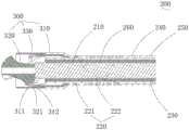
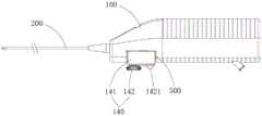
本发明的实施例一提出了一种切除装置,如图1至图3所示, 包括手柄本体100、连通于手柄本体100的导管200以及设置在导管 200远端的刀头组件300,导管200内设置有连接于刀头组件300的 扭矩轴210。结合图5所示,导管200上设置有用于调弯导管200 远端部位的调弯组件220,手柄本体100上设置有可拆卸连接于手柄 本体100的驱动机构400。结合图11所示,驱动机构400包括用于 驱动扭矩轴210转动的驱动模块410以及用于控制驱动模块410以 调节扭矩轴210扭矩的调节模块420。Embodiment 1 of the present invention proposes a resection device, as shown in FIGS. A
本发明通过调弯组件220调节远端导管200的弯曲半径,使导 管200朝向预定方向偏移,并控制刀头组件300的朝向,降低刮伤 血管及血管穿孔的风险,能够通过多次切除得到理想的血管管径; 同时,设置用于调节扭矩轴210扭矩的调节模块420,以使斑块切除 装置在切除较硬的斑块时,可以通过调整扭矩轴210的扭矩使斑块 切除更加顺畅;另一方面,通过设置可拆卸连接于手柄本体100的 驱动机构400,以使驱动机构400可以循环使用,降低斑块切除装置 的使用成本。In the present invention, the bending radius of the
具体的,如图4所示,刀头组件300包括连接于导管200的限 位座310以及设置在限位座310上的旋切刀头320,旋切刀头320 固定连接于扭矩轴210的一端,扭矩轴210驱动旋切刀头320转动 连接于限位座310,限位座310上设置有罩设在旋切刀头320侧面的 保护套330。Specifically, as shown in FIG. 4 , the
如图5所示,导管200包括内管230以及设置在内管230外侧 的外管240,内管230套设在扭矩轴210的外侧,扭矩轴210与内管 230为间隙配合,扭矩轴210贯穿内管230的整个内腔。As shown in FIG. 5 , the
进一步地,内管230与外管240之间设置有编织层250,其中, 编织层250具体为编织网,编织网通过镍钛丝编织形成。内管230 和外管240之间通过编织层250连接,从而增强了导管200的韧性, 在导管200穿入分支血管,或者通过血管的弯曲部位时,导管200 不会出现局部凹陷折弯的现象,能够保证导管200的管腔完整,保 证了切除的斑块的通过性,使斑块不会堵在导管200折弯处。Further, a
具体的,旋切刀头320通过焊接的方式固定在扭矩轴210的端 部,扭矩轴210转动从而带动旋切刀头320转动。旋切刀头320上 设置有刀头卡槽321,限位座310的远端设置有限位凸台311,限位 凸台311与刀头卡槽321卡接配合,从而实现旋切刀头320与限位 座310之间的轴向和径向限位。Specifically, the
其中,旋切刀头320、限位座310与保护套330均为不锈钢材质。 同时,限位座310的远端设置有具有弹性的弹片312,限位凸台311 设置在弹片312上。由于刀头组件300整体通过硬质金属材质制成, 因此旋切刀头320与限位座310的装配工艺复杂。本实施例通过在限位座310的远端设置弹片312,而弹片312具有弹性,能够在装配 时产生弹性形变,以使限位凸台311顺利的卡入刀头卡槽321中。 保护套330罩设在限位座310的外侧,同时保护套330紧贴限位座310的外表面,因此在完成保护套330的装配后,弹片312被限制在 旋切刀头320与保护套310之间,从而完成限位凸台312与刀头卡 槽321的卡接配合,进而实现旋切刀头320与限位座310之间的轴 向和径向限位。Wherein, the
导管200由内至外依次包括内管230、编织层250以及外管240, 并且内管230、编织层250以及外管240通过热熔的方式形成一个整 体。进一步地,导管200的远端设置有弹簧管260,弹簧管260套设 在编织层250的外侧,或编织层250套设在弹簧管260的外侧,弹 簧管260通过焊接的方式与编织层250轴向固定。在本实施例中, 弹簧管260套设在编织层250的外侧。通过在导管200的远端设置 弹簧管260,从而增强导管200远端的顺应性和回弹性。在其他实施 例中,弹簧管260还可以埋设在外管240内。The
本申请中,由于编织层250的抗折弯性能好,弹簧管260的抗 扭矩性能好。因此,导管200内设置编织层250,并且采用在导管 200的远端设置弹簧管260的结构,能够使得导管200远端能够兼顾 抗折弯以及抗扭矩性能,当导管200进行调弯时,通过编织层250 与弹簧管260的配合,避免了导管200因弯曲而出现局部的内凹形 变,能够在实现导管200弯曲的情况下,维持导管200的管腔的形 变,保证导管200与扭矩轴210之间的间隙足够通过斑块或血栓, 确保手术顺利进行。同时还能够保持良好的血管通过性,使得导管 200在进入较复杂弯曲的血管时,更加顺畅。In the present application, due to the good bending resistance of the
保护套330与外管240通过热熔的方式固定,外管240为TPU 管或Pebax管,在本实施例中,外管240采用Pebax材质。The
其中,结合图2,导管200上设置有缓冲套管270,导管200通 过缓冲套管270与手柄本体100连接,缓冲套管270与手柄本体100 的外壳通过卡合方式配合连接,缓冲套管270为TPU材质,或者其 他橡胶或者塑料材质。缓冲套管270设置为软性材质,能够消除导 管200在旋切时的震动,传递至手柄本体100的震动会明显减小, 从而为操作者的精细操作提供条件。Wherein, referring to FIG. 2 , a
进一步地,结合图11与图12所示,驱动机构400还包括驱动 壳体430、动力源411以及用于连接动力源411与扭矩轴210的驱动 传动组件412。调节模块420包括与驱动传动组件412连接的调节传 动组件421以及换挡组件422,换挡组件422用于控制调节传动组件421与驱动传动组件412的配合关系以调节扭矩轴210的扭矩,驱动 壳体430内设置有用于驱动动力源411的电源组件413。Further, as shown in FIG. 11 and FIG. 12 , the
具体的,动力源411为设置在驱动壳体430内的电机,电源组 件413为设置在驱动壳体430内的电池,电池与电机电性连接。电 源组件413为动力源411供电,动力源411通过驱动传动组件412 带动扭矩轴210转动,扭矩轴210转动以使设置在远端的旋切刀头 320转动,从而切除血管中的斑块。手柄本体100上还设置有开关 160,通过开关160控制电机的工作状态。Specifically, the
在其他实施例中,还可以在驱动壳体430上设置用于连接外部 电源且电性连接于动力源411的电源组件413。即当需要驱动动力源 411工作时,通过电源组件413连接外部电源,电源组件413包括设 置在驱动壳体430上的电源插口。通过设置电源插口的形式,能够降低手柄本体100及内部元器件杀菌消毒的难度及成本,并降低整 机的重量和运输难度。In other embodiments, a
进一步地,结合图2所示,手柄本体100上设置有连接于导管 200的排出腔道500,排出腔道500连通于导管200与手柄本体100 的外部空间,扭矩轴210穿过排出腔道500并连接于驱动机构400。 排出腔道500包括连通于导管200的主腔体510以及设置在主腔体 510侧面的排废管520,扭矩轴210穿过主腔体510且连通于手柄本 体100的外部空间,扭矩轴210内设置有贯通扭矩轴210的导丝腔 211。Further, as shown in FIG. 2 , the
具体的,扭矩轴210呈螺旋状设置。在斑块切除装置工作时, 电机驱动扭矩轴210转动,由于扭矩轴210呈螺旋状设置,因此扭 矩轴210可以在转动的过程中将斑块组织向后带出导管200。Specifically, the
扭矩轴210内的导丝腔211用于穿入导丝,导丝用于在导管200 伸入血管或者移动之前,先伸入血管或者分支血管,以建立导管200 的路入通路,使得导管200能够沿导丝建立的路入通路移动。The
其中,外管240的近端与主腔体510粘接固定,由旋切刀头320 切除的斑块组织通过扭矩轴210与内管230之间的间隙,随着扭矩 轴210的转动从导管200中排出到排出腔道500内,排出腔道500 的主腔体510暂时容纳切除的斑块组织,并最终通过排废管520将 斑块组织排出。排废管520设置在靠近主腔体510的近端部位,并 且沿斑块切除的方向倾斜设置,从而便于斑块的排出。Wherein, the proximal end of the
在本实施例中,如图5至图7所示,手柄本体100上设置有用 于控制调弯组件220的控制组件140,调弯组件220包括至少两个调 弯点221以及用于连接调弯点221的调弯连接件222。结合图3所示, 控制组件140包括设置在手柄本体100上的控制座141以及活动连 接于控制座141的收线器142,收线器142用于连接调弯连接件222 且用于牵拉调弯连接件222以调整导管200的姿态。In this embodiment, as shown in FIGS. 5 to 7 , the
其中,调弯点221包括设置在导管200上的第一调弯点2213以 及第二调弯点2214,调弯连接件222与第一调弯点2213固定连接, 调弯连接件222与第二调弯点2214活动连接,第一调弯点2213与 导管200远端的距离相比第二调弯点2214与导管200远端的距离更 小,第一调弯点2213设置在相对于第二调弯点2214的另一侧。Wherein, the
调弯连接件222包括调弯控制线2225,导管200上设置有用于 调弯控制线2225穿过的控制线腔2226,第二调弯点2214设置在控 制线腔2226的远端,调弯控制线2225穿过第二调弯点2214且绕导 管200旋转后固定连接于第一调弯点2213。在本实施例中,为了使 刀头组件300的朝向与导管200相同,因此第一调弯点2213和第二 调弯点2214在周向上相差180度设置。The
具体的,导管200内设置有控制线腔2226,控制线腔2226可以 设置在外管240的内部或者内管230的内部。其中,第一调弯点2213 为固定设置在编织层250上的固定点,通过固定点与调弯控制线 2225固定连接,第二调弯点2214为控制线腔2226远端的端点。Specifically, the
在本实施例中,第一调弯点2213为焊接固定在编织层250上的 固定环,固定环将调弯控制线2225压紧固定在编织层250上,或者 调弯控制线2225与固定环焊接固定。通过将第一调弯点2213设置 为环形,从而满足调弯控制线2225的多相位连接,方便调弯控制线的角度调节和固定。In this embodiment, the
调弯控制线2225的一端连接于收线器142,调弯控制线2225 的另一端首先穿出控制线腔2226,然后顺着内管230与编织层250 之间的间隙螺旋旋转180度后,固定在第一调弯点2213上。其中, 调弯控制线2225的旋转角度还可以为170度或者190度,只要保证 第二调弯点2214相对设置在第一调弯点2213的对侧,即可保证在 调弯后,刀头组件300的朝向与导管200大致相同。One end of the bending
进一步地,调弯控制线2225伸出第二调弯点2214并固定在第 一调弯点2213之间的螺旋部分的轴向长度设置为外管240外径尺寸 的1倍至3倍。若第一调弯点2213与第二调弯点2214之间的轴向 长度过长,则会导致调弯效果不佳。若第一调弯点2213与第二调弯点2214之间的轴向长度过短,则会导致调弯所需应力过大,不利于 操作。因此,在本实施例中,调弯控制线2225伸出第二调弯点2214 并固定在第一调弯点2213之间的螺旋部分的轴向长度设置为外管 240外径尺寸的2倍。Further, the axial length of the bending
进一步地,本实施例通过调节收线器142,控制调弯控制线2225 在控制线腔2226或者内管230中移动,由于调弯控制线2225在导 管200的远端沿着内管230螺旋旋转180度,因此控制调弯控制线 2225收缩时,调弯控制线2225对导管200远端既有轴向作用力、也 有径向作用力,从而能控制刀头组件300轴向及径向位移,故而使 刀头组件300实现S形调弯。由于调弯控制线2225旋转180度,因 此能够使刀头组件300与导管200轴向保持相同方向,降低刀头组 件300擦伤血管壁的风险。而刀头组件300调弯前与调弯后切除血 管内斑块,能使血管获得更大的管腔。Further, the present embodiment controls the bending
如图8至图10所示,本实施例的控制组件包括设置在手柄本体 上的控制座以及活动连接于控制座的收线器,收线器包括用于自锁 定的锁定件1421。As shown in Figures 8 to 10, the control assembly of this embodiment includes a control seat arranged on the handle body and a wire retractor movably connected to the control seat, and the wire retractor includes a locking
手柄本体100上设置有控制槽150,控制组件140设置在控制槽 150内,控制槽150的一端设置有顶杆151,控制座141朝向顶杆151 的一端设置有顶槽1411,控制座141的另一端转动连接于控制槽150 的另一端。从而控制座141通过顶槽1411与顶杆151的配合轴向固定在控制槽150内,且控制座141能够通过顶槽1411与顶杆151的 配合,转动连接于手柄本体100。The
收线器142设置在控制座141内,收线器142上设置有用于夹 持调弯控制线2225的夹持部143。其中,锁定件1421为设置在控制 座141的内壁的内螺纹以及设置在收线器142的外壁上设置的外螺 纹,收线器142与控制座141通过螺纹连接,且控制座上的内螺纹 与收线器上的外螺纹为自锁螺纹配合。医生在松开收线器以后,收 线器因内螺纹与外螺纹相对自锁而不会与控制座相对移动,从而实 现收线器的自锁定。The wire take-
控制座141内设置有滑杆144,滑杆144沿控制座141的轴向方 向设置,收线器142滑动连接于滑杆144,滑杆144与收线器142 之间设置有转动限位面1441,从而收线器142能够沿滑杆144的长 度方向平移,不能与滑杆144相对转动,即形成丝杆联动关系。A
因此,当转动控制座141时,收线器142在螺纹配合的联动下 能够在滑杆144上滑移并相对控制座141移动,并且收线器142夹 持调弯控制线2225,调弯控制线2225跟随收线器142相对手柄本体 100移动,从而控制导管200进行弯曲动作。Therefore, when the
在本申请的进一步实施例中,如图11至图15示,驱动传动组 件412包括与扭矩轴210连接的第一传动件4121、与动力源411连 接的第二传动件4122以及设置在驱动壳体430上的第三传动件 4123,第三传动件4123连接在第一传动件4121与第二传动件4122 之间。In a further embodiment of the present application, as shown in FIGS. 11 to 15 , the
如图13所示,调节传动组件421包括与第二传动件4122同轴 设置的第四传动件4211以及与第三传动件4123同轴设置的第五传 动件4212,换挡组件422包括连接于动力源411的输出轴的主动轮 轴4221以及连接于主动轮轴4221的拨杆4222,第三传动件4123 与第五传动件4212均设置在主动轮轴4221上,主动轮轴4221与输 出轴滑动连接且同步转动;拨杆4222用于驱动第二传动件4122与 第三传动件4123连接或驱动第四传动件4211与第五传动件4212连 接。As shown in FIG. 13 , the
具体的,本实施例的传动件均为齿轮。其中,动力源411为电 机,第一传动件4121为连接于扭矩轴210的输出齿轮,第二传动件4122为连接于电机的主动齿轮,第三传动件4123为设置在驱动壳体 430上的传动齿轮。主动齿轮、传动齿轮和输出齿轮依次啮合连接。Specifically, the transmission elements in this embodiment are all gears. Wherein, the
另外,本实施例的调节传动组件421设置了第二组齿轮组件, 即第四传动件4211和第五传动件4212。其中,第四传动件4211为 与第二传动件4122同轴设置的大调速齿轮,第五传动件4212为与 第三传动件4123同轴设置的小调速齿轮。In addition, the
具体的,第四传动件4211为与第二传动件4122均设置在主动 轮轴4221上,电机直接驱动输出轴转动,主动轮轴4221滑动连接 于电机的输出轴且与电机的输出轴同步转动。第五传动件4212通过 从动轮轴4224连接于第三传动件4123,第五传动件4212与第三传 动件4123通过从动轮轴4224同轴转动。Specifically, the
其中,主动轮轴4221与拨杆4222固定连接,拨杆4222的末端 设置有调速键4223,调速键4223滑动连接于手柄本体100。如图15 所示,驱动壳体430上设置有低速限位槽4113以及高速限位槽4113, 当旋切刀头320处于低速挡切割时,调速键4223位于低速限位槽4113,且第二传动件4122、第三传动件4123和第一传动件4121依 次啮合连接。Wherein, the
本实施例的驱动模块410具体工作原理如下:当动力源411工 作,并通过动力源411带动第二传动件4122转动时,即电机开始运 转并带动第二传动件4122运转。第二传动件4122通过与第三传动 件4123啮合将转速传递给第三传动件4123,第三传动件4123通过与第一传动件4121啮合将速度传递给第一传动件4121,第一传动件4121再将速度传递给扭矩轴210,扭矩轴210带动旋切刀头320转 动,完成低速挡切割。低速挡切割时,扭矩轴的转速较底,而扭矩 较大。The specific working principle of the
当进行高低档位切换时,拨动调速键4223,以使调速键4223 移动至高速限位槽4113,拨杆4222在调速键4223的带动下移动, 调速杆的移动带动主动轮轴4221移动并使第二传动件4122与第三 传动件4123脱离啮合。由于第四传动件4211与第二传动件4122均 设置在主动轮轴4221上,因此第四传动件4211也跟随主动轮轴4221 一起移动,并与第五传动件4212啮合,完成齿轮啮合关系的切换。When switching between high and low gears, toggle the speed regulating key 4223 so that the speed regulating key 4223 moves to the high-
在本实施例中,第四传动件4211的齿数大于第二传动件4122 的齿数,第五传动件4212的齿数小于第三传动件4123的齿数。因 此,第四传动件4211与第五传动件4212相啮合的传动状态,与第 二传动件4122与从动齿轮相啮合传动状态相比,第五传动件4212 的转速更高。In this embodiment, the number of teeth of the
由于第五传动件4212的转速更高,且第五传动件4212将更高 的转速通过从动轮轴4224传递至第三传动件4123,第三传动件4123 与第一传动件4121相啮合,从而第一传动件4121的转速更高,完 成旋切刀头320的高速挡切割。当高速挡切割时,扭矩轴的转速更高,而扭矩较小。Since the rotation speed of the
基于本实施例的上述方案,通过在调节模块420中设置额外的 齿轮组,即第四传动件4211和第五传动件4212,并通过换挡组件 422调节各齿轮组件之间的啮合关系,从而实现了旋切刀头320转速 的高速、低速挡位可调,进而实现了旋切刀头320扭矩的高扭矩、低扭矩可调。医生可以根据斑块的质地灵活选用切割速度,避免刀 头卡停的现象,提高了使用的稳定性,避免血管损伤。Based on the above solution of this embodiment, by setting an additional gear set in the
在常规切割时,医生可以选用高速挡,从而实现斑块切除效率 的最大化。当遇到斑块堵塞或者斑块难以切除的情况时,尤其是因 导管200调弯而导致斑块或血栓卡在导管200的弯曲部位时,医生 可以选用低速挡以提高扭矩轴210的扭矩,避免斑块或血栓难以通过导管200的弯曲部位,保证导管200不会发生堵塞,并避免旋切 刀头320卡停的情况发生,保证手术的顺利进行。During routine cutting, doctors can choose high-speed gear to maximize the efficiency of plaque removal. When the plaque is blocked or difficult to remove, especially when the plaque or thrombus is stuck in the bending part of the
在其他实施例中,还可以设置额外的齿轮组件,以增加可调挡 位的数量,例如实现三挡可调,从而为医生提供更多的选择。并且, 上述调速方案仅为示例,任何可以实现扭矩轴扭矩调整的机械结构 均在本申请的保护范围内。In other embodiments, an additional gear assembly can also be provided to increase the number of adjustable gears, for example, to realize three gears adjustable, thereby providing doctors with more choices. Moreover, the above-mentioned speed regulation scheme is only an example, and any mechanical structure that can realize the torque adjustment of the torque shaft is within the protection scope of the present application.
在其他实施例中,当采用外接电源的驱动方式时,还可以通过 动态调整外接电源的输出功率的方式,以动态的控制扭矩轴的输出 扭矩,从而保证使用的稳定性。In other embodiments, when the drive mode of the external power supply is adopted, the output torque of the torque shaft can be dynamically controlled by dynamically adjusting the output power of the external power supply, so as to ensure the stability of use.
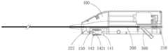
进一步地,如图16至图21所示,手柄本体100上设置有用于 装配驱动机构400的装配部110,驱动机构400包括用于容纳驱动模 块410与调节模块420的驱动壳体430,驱动壳体430与装配部110 之间设置有拆卸连接部130。其中,驱动传动组件412与手柄本体 100之间设置有密封结构4124。Further, as shown in FIG. 16 to FIG. 21 , the
本实施例通过驱动机构400可拆卸式设计,首先,为前期灭菌 提供了便利,能够对驱动机构400中灭菌难度较大的电源组件413 进行单独灭菌,然后通过拆卸连接部130进行快速组装,降低了切 除装置整体的灭菌难度以及生产装配速度,提高了生产效率。其次,在切除装置使用以后,拆卸得到的零部件可以根据医用规范允许范 围内二次使用,提高了零部件的利用率,降低了使用成本。另外, 在切除装置在使用完毕以后,可以快速的将各个零部件进行拆卸, 根据医用规范灵活的进行分类回收与报废,降低了回收难度及成本。In this embodiment, through the detachable design of the
拆卸连接部130包括设置在装配部110与驱动壳体430之间的 钩挂组件131以及卡合组件132,钩挂组件131与卡合组件132分别 设置在装配部110的两端,驱动壳体430与装配部110的底部之间 设置有弹出件133。The
具体的,装配部110为设置在手柄本体100上用于安装驱动机 构400的装配槽,驱动机构400设置在装配部110内,且驱动机构 400可拆卸连接于手柄本体100。驱动机构400具体通过驱动壳体430 可拆卸连接于装配部110的方式,实现驱动机构400整体的可拆卸更换,驱动模块410和调节模块420均安装在驱动壳体430内。Specifically, the
本实施例通过将驱动机构400整体设置为可拆卸结构,从而驱 动机构400在符合规范的情况下,可循环使用。并且驱动机构400 和手柄本体100可以根据医用使用规范进行分类回收。In this embodiment, the
进一步地,如图18所示,卡合组件132设置在手柄本体100的 近端,钩挂组件131设置在手柄本体100的远端。卡合组件132包 括滑动连接于驱动壳体430的锁紧销1321以及设置在锁紧销1321 上的锁紧键1322,锁紧键1322与锁紧销1321一体成型,或者锁紧 销1321与锁紧键1322分体成型后粘接固定。Further, as shown in FIG. 18 , the engaging
装配部110的内壁上设置有用于与锁紧销1321卡合连接的锁紧 孔1323,用户可以通过拨动锁紧键1322带动锁紧销1321移动,并 控制锁紧销1321插入锁紧孔1323中以实现锁紧销1321与锁紧孔 1323的固定,或者控制锁紧销1321脱离与锁紧孔1323的插接以实 现锁紧销1321与锁紧孔1323的分离。当锁紧销1321插入锁紧孔 1323中时,驱动机构400与装配部110处于固定状态,当锁紧销1321 脱离锁紧孔1323时,驱动机构400与装配部110处于分离状态。The inner wall of the
其中,锁紧键1322的底部设置有锁紧卡件1324,驱动壳体430 表面上设置有锁定固定槽1325和分离固定槽1326,分离固定槽1326 相对锁定固定槽1325远离锁紧孔1323设置,锁定固定槽1325与分 离固定槽1326分别用于与锁紧卡件1324卡合固定。当锁紧键1322带动锁紧销1321朝向靠近锁紧孔1323的方向移动,并使锁紧卡件 1324卡合连接于锁定固定槽1325内时,锁紧销1321插入锁紧孔1323 中,并使得驱动机构400与装配部110卡接固定。当锁紧键1322带 动锁紧销1321朝向远离锁紧孔1323的方向移动,并使锁紧卡件1324卡合连接于分离固定槽1326内时,锁紧销1321与锁紧孔1323分离, 并使得驱动机构400与装配部110分离。Wherein, the bottom of the locking key 1322 is provided with a locking clip 1324, and the surface of the driving
其中,驱动壳体430与装配部110的底部之间设置有用于将驱 动机构400弹出的弹出件133,弹出件133优选为弹簧。即当锁紧销 1321与锁紧孔1323脱离后,弹出件133自动将驱动机构400从装配 部110内弹起,从而方便用户将驱动机构400取出。Wherein, an ejecting
钩挂组件131设置在驱动壳体430相对锁紧销1321的另一端, 钩挂组件131包括设置在驱动壳体430远端端面上的挂钩1311以及 设置在装配部110的内表面且与挂钩1311钩挂连接的钩挂槽1312。The hooking
在将驱动机构400固定在装配部110内时,首先将挂钩1311与 钩挂槽1312钩挂连接,从而实现驱动机构400的远端与装配部110 固定,然后将卡合组件132的锁紧键1322与锁紧孔1323插接,实 现驱动机构400的远端与装配部110固定。When fixing the
在将驱动机构400从装配部110内取出时,首先将卡合组件132 的锁紧键1322与锁紧孔1323分离,实现驱动机构400的近端与装 配部110分离,然后将挂钩1311从钩挂槽1312中取出,实现驱动 机构400的远端与装配部110分离。When the
在本实施例中,手柄本体100上还设置有可拆卸连接于手柄本 体100且设置在驱动机构400外侧的手柄上盖120。In this embodiment, the
其中,结合图19所示,手柄上盖120的远端与手柄本体100的 钩挂槽1312通过卡合结构固定,手柄上盖120的远端设置有上盖插 销123,其中,上盖插销123插接连接于钩挂槽1312。手柄上盖120 的近端设置有插板121,插板121设置在驱动壳体430与钩挂槽1312 之间,插板121上设置有与锁紧销1321配合的插孔122。当手柄上 盖120的上盖插销123与钩挂槽1312卡合固定后,将手柄本体100 贴合驱动壳体430设置,然后操作锁紧键1322朝向锁紧孔1323的 方向移动。锁紧键1322首先穿过插板121上的插孔122,然后插入 缩进孔中,实现同时将手柄上盖120和驱动机构400固定在手柄本 体100上的目的。Wherein, as shown in FIG. 19 , the far end of the handle
本申请通过在驱动机构400上设置手柄上盖120的方式,保护 了驱动机构400,防止驱动机构400因外界碰撞等因素损坏。另外, 在将手柄本体100与驱动机构400拆卸后,可以根据相关理疗规定 对相关拆分件进行分类回收与报废。The present application protects the
在本实施例中,调弯组件220设置在手柄本体100的远端,从 而方便医生在术中的操作,导管200从手柄本体100的远端穿入手 柄本体100,导管200与手柄本体100通过缓冲套管270连接,导管 200的近端固定于设置在手柄本体100中部的排出腔道500。In this embodiment, the bending
排出腔道500设置在手柄本体100的中部,扭矩轴210贯穿手 柄本体100,扭矩轴210首先贯穿导管200并从导管200中穿入主腔 体510,从导管200中被送出的斑块或血栓掉落至主腔体510中, 并从排废管中排出,排废管相对主腔体510倾斜设置,便于斑块或 血栓排出。The
扭矩轴210从排出腔道500中穿出,并通过一轴承连接于手柄 本体100,扭矩轴210的导丝腔211连通于手柄本体100的外部空间, 从而导丝通过导丝腔211贯穿扭矩轴210并从扭矩轴210的远端穿 出,从而为导管200建立路入血管的通路。The
其中,驱动机构400设置在导管200以及排出腔道500的上方, 驱动传动组件412设置在排出腔道500的近端并与扭矩轴210连接。 从而斑块或者血栓通过设置在驱动传动组件412远端的排出腔道500排出手柄本体100,斑块或者血栓不会接触到驱动传动组件412。Wherein, the
并且驱动传动组件412与排出腔道500之间采用密封设计,即 第一传动件4121与手柄本体100之间设置有密封结构4124,密封结 构4124包括固定在手柄本体100上的滚动轴承以及用于密封滚动轴 承的密封圈,扭矩轴210穿过滚动轴承,并与滚动轴承固定并密封 连接。具体的,可通过焊料填满扭矩轴210与滚动轴承之间的间隙, 并焊接固定,然后通过密封圈对滚动轴承与手柄本体100进行密封。 从而,本实施例的驱动机构400在使用后能够保持洁净,从而便于 回收,并且能够二次利用。In addition, a sealing design is adopted between the driving
综上,本申请通过调弯组件220调节远端导管200的弯曲半径, 使导管200朝向预定方向偏移,并控制刀头组件300的朝向,降低 刮伤血管及血管穿孔的风险,能够通过多次切除得到理想的血管管 径。同时,设置用于调节扭矩轴210扭矩的调节模块420,以使斑块切除装置在切除较硬的斑块时,可以通过调整扭矩轴210的扭矩使 斑块切除更加顺畅。另一方面,通过设置可拆卸连接于手柄本体100 的驱动机构400,以使驱动机构400可以循环使用,降低斑块切除装 置的使用成本。To sum up, the present application uses the bending
实施例二Embodiment two
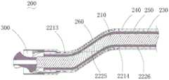
本发明的实施例二提出了一种切除装置,如图22所示,实施例 二与实施例一的相同之处不再赘述,实施例二与实施例一的不同之 处在于,调弯点221包括设置在导管200上的调弯固定件2211以及 设置在刀头组件300上的回位固定件2212,调弯连接件222用于连接调弯固定件2211和回位固定件2212,回位固定件2212设置在刀 头组件300的近端,调弯固定件2211设置在导管200相对于回位固 定件2212的另一侧。Embodiment 2 of the present invention proposes a resection device, as shown in FIG. 22 , and the similarities between Embodiment 2 and Embodiment 1 will not be repeated. The difference between Embodiment 2 and Embodiment 1 is that the
调弯连接件222包括调弯连接线2221以及回位连接线2222,导 管200上设置有用于调弯连接线2221穿过的调弯线腔2223以及用 于回位连接线2222穿过的回位线腔2224。调弯连接线2221用于连 接控制组件140以及调弯固定件2211,回位连接线2222用于连接控制组件140以及回位固定件2212。The
回位固定件2212设置在刀头组件300的近端,调弯固定件2211 设置在导管200相对于回位固定件2212的另一侧。调弯固定件2211 设置在导管200相对于回位固定件2212的另一侧,优选调弯固定件 2211与回位固定件2212在周向上相差180度设置。The
具体的,导管200内设置有调弯线腔2223以及回位线腔2224, 调弯线腔2223和回位线腔2224均设置在外管240中或者设置在外 管240与编织层250之间。调弯连接线2221的一端连接于调弯固定 件2211,然后贯穿调弯线腔2223后,另一端连接于控制组件140。 回位连接线2222的一端连接于调弯固定件2211,然后贯穿回位线腔 2224后,另一端连接于控制组件140。Specifically, the
调弯连接线2221与回位连接线2222分别固定在收线器142上, 当医生转动控制座141时,收线器142在滑杆144上相对控制座141 滑移,从而同时牵拉调弯连接线2221和回位连接线2222,从而调整 导管200和刀头组件300的姿态。The bending
其中,回位固定件2212设置在保护套330上,回位固定件2212 为设置在保护套330上的固定板,回位连接线2222与固定板焊接固 定,或者回位固定件2212上设置有连接孔,回位连接线2222穿过 连接孔并打结固定。调弯固定件2211为设置在导管200的编织层250上的固定环,固定环将调弯连接线2221压紧固定在编织层250上, 或者调弯连接线2221与固定环焊接固定。Wherein, the
由于调弯固定件2211设置在导管200相对于回位固定件2212 的另一侧,因此当收线器142同时牵拉调弯连接线2221和回位连接 线2222时,调弯连接线2221通过调弯固定件2211控制导管200轴 向位移,回位固定件2212通过回位固定件2212控制刀头组件300 径向位移。在调弯连接线2221和回位连接线2222的综合作用下, 使刀头组件300实现S形调弯,从而使刀头组件300与导管200轴 向保持相同方向,降低刀头组件300擦伤血管壁的风险。而刀头组 件300调弯前与调弯后切除血管内斑块,能使血管获得更大的管腔。Since the bending
本实施例通过调弯组件220实现了导管200与刀头组件300的S 形调弯,从而在切割血管内斑块时,可以通过调弯导管200和刀头 组件300,使得切割的面积增大。同时,由于刀头组件300在回位固 定件2212的作用下,与导管200的轴向基本保证方向相同,因此在刀头组件300推进过程中,不会误切割血管壁,大大降低了刀头组 件300擦伤血管壁的风险。相比现有技术的调弯方式,本申请既能 够使血管获得更大的管腔,又能保证切割时的安全性。In this embodiment, the S-shaped bending of the
实施例三Embodiment three
本发明的实施例三提出了一种切除装置,如图23与图24所示, 实施例三与实施例一的相同之处不再赘述,实施例三与实施例一的 不同之处在于,手柄本体100上设置有控制槽150,控制组件140 设置在控制槽150内,控制座141卡合固定在控制槽150内,收线 器142包括滑动连接于控制座141的滑钮145以及设置在滑钮145 上的接线点1451,接线点1451用于连接调弯连接件222,调弯连接 件222为调弯连接线2221。Embodiment 3 of the present invention proposes a resection device, as shown in FIG. 23 and FIG. 24 , the similarities between Embodiment 3 and Embodiment 1 will not be repeated, and the difference between Embodiment 3 and Embodiment 1 is that The
具体的,控制座141上设置有滑槽1412以及滑动连接于滑槽 1412的滑块1413,滑槽1412沿控制座141的长度方向设置。滑块 1413上设置有固定孔1414,控制座141的滑钮145朝向滑块1413 的一端设置有固定柱1452,固定柱1452穿过在固定孔1414,以使 滑钮145通过固定柱1452连接于滑块1413。滑钮145与滑块1413 之间设置有控制弹簧146,滑钮145与滑块1413同时滑动连接于控 制座141,且控制弹簧146具有初始压力,使得滑钮145紧贴于控制 座141内壁。Specifically, the
其中,所述锁定件1421为设置在滑钮145与控制座141之间的 粗糙接触面,当控制组件140处于自然状态时,控制弹簧146驱动 滑钮145紧贴于控制座141的内壁,由于滑钮145与控制座141之 间设置有粗糙接触面,因此滑钮145与控制座141在摩擦力的作用 下不会相对移动,实现收线器142的自锁定。当向控制座141的内 部按压滑钮145时,控制弹簧146受力压缩,且滑钮145与控制座 141分离,此时滑钮145可以相对控制座141移动。Wherein, the locking
在其他实施例中,锁定件1421还可以为设置在滑钮145与控制 座141之间且相互卡合的凸点与凹槽结构,以增强滑钮145和控制 座141在贴合时的结合强度。在自然状态下,控制弹簧146驱动滑 钮145紧贴于控制座141内壁,从而通过凸点与凹槽结构相互卡合,实现收线器142的自锁定。In other embodiments, the locking
在本实施例中,滑钮145上设置有螺纹孔,接线点1451为螺纹 连接于滑钮145的螺丝,在装配时,将调弯连接件222粘接固定在 螺纹孔中,然后将螺丝拧入螺纹孔中进行二次固定。In this embodiment, the sliding
具体操作时,操作者通过按压滑钮145,以使滑钮145与控制座 141的贴合面分离,弹簧沿导管200的轴向方向滑动滑钮145,带动 调弯连接件222沿导管200的轴向方向移动,实现导管200的姿态 调整,对刀头组件300进行调弯。手术过程中,操作者不需要一直 按压滑钮145,同时,操作者仅需要单手即可实现刀头组件300的调 弯操作,减轻了操作负担,提高了操作便利性。另外,通过平移的 调节方式,调节行程精确,可以实现调弯角度的精确可控。During specific operation, the operator presses the sliding
实施例四Embodiment four
本发明的实施例四提出了一种切除装置,如图25至图27所示, 实施例四与实施例一的相同之处不再赘述,实施例四与实施例一的 不同之处在于,手柄本体100上设置有控制槽150,控制组件140 设置在控制槽150内,控制座141卡合固定在控制槽150内,收线 器142包括转动连接于控制座141的旋钮147以及用于卡合所述旋 钮的锁定件1421,锁定件1421为用于将旋钮147卡合固定的止动销148,止动销148滑动连接于控制座141,旋钮147上设置有与止动 销148卡合连接的止动槽1472。其中,止动销148与控制座141的 内壁之间设置有止动弹簧1481。Embodiment 4 of the present invention proposes a resection device, as shown in FIG. 25 to FIG. 27 , the similarities between Embodiment 4 and Embodiment 1 will not be repeated, and the difference between Embodiment 4 and Embodiment 1 is that The
旋钮147上设置有旋转夹块1471,旋转夹块1471用于连接调弯 连接件222,调弯连接件222为调弯连接线2221,转动旋钮147以 使调弯连接件222缠绕在旋转夹块1471上,从而实现牵拉调弯连接 件222以调整导管200姿态的目的。在自然状态下,止动弹簧1481 驱动止动销朝向旋钮147的方向移动,并卡接在止动槽1472内。当 需要转动旋钮147时,向远离旋钮147的方向滑动止动销148,以使 止动销148与止动槽1472分离,此时可转动旋钮147。当需要锁定 旋钮147时,放开止动销148,止动弹簧1481驱动止动销148朝向 靠近旋钮147的方向滑动,以使止动销148与止动槽1472卡合,此 时旋钮147不可转动。The
在本申请进一步实施方案中,控制组件140还包括用于防止误 触的锁定保险组件1422,所述锁定保险组件1422设置在控制座141 与收线器142之间。In a further embodiment of the present application, the
具体的,控制座141内还设置有定位柱1415,定位柱1415上套 设有定位弹簧1416,定位弹簧1416设置在控制座141与旋钮147 之间。其中,旋钮147可以沿自身轴向方向移动,且旋转夹块1471 与控制座141之间设置有锁定保险组件1422,其中,锁定保险组件 1422为卡位结构149。其中,卡位结构149包括设置在旋转夹块1471 朝向旋钮147一端的卡位槽1491以及设置在控制座141朝向旋转夹 块1471一端的卡位块1492,当卡位块1492与卡位槽1491卡合固定 时,旋钮147无法转动。Specifically, the
在具体操作时,在自然状态下,定位弹簧1416向外推动旋钮 147,以使旋转夹块1471与控制座141之间的卡位结构149卡合固 定。同时,止动销148在止动弹簧1481的驱动下与止动槽1472处 于卡合状态。而当止动销148插接在止动槽1472中时,止动销148 位于旋钮147与控制座141之间,挡住了旋钮147轴向移动的路径, 因此旋钮147无法按压,也无法解除卡位块1492与卡位槽1491的 卡合连接,因此,在自然状态下,旋钮147无法转动。当需要转动 旋钮147时,操作者首先向远离旋钮147的方向滑动止动销148,以 使止动销148与止动槽1472分离,然后向内按压旋钮147,定位弹 簧1416受力被压缩,同时使卡位结构149分离,即卡位块1492与 卡位槽1491分离,此时可以转动旋钮147。During specific operation, in a natural state, the
因此,本实施例的控制组件140通过在控制座141与收线器142 之间设置额外的锁定保险组件1422,实现了收线器142的双重锁定, 提高了结构的可靠性,保证了医生在推进刀头组件300以切割斑块 时,刀头组件300的姿态不会发生变化。仅当医生同时推动止动销148并按压旋钮147时,才能转动旋钮147,不会因为误触而导致刀 头组件300的朝向发生变化,避免了旋切刀头320切伤血管,从而 避免医疗事故的发生,进而保证了手术的顺利进行。Therefore, the
实施例五Embodiment five
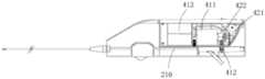
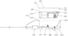
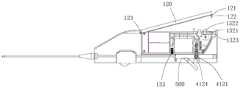
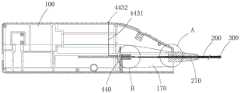
本发明的实施例五提出了一种切除装置,如图29至图33所示, 实施例五与实施例一的相同之处不再赘述,实施例五与实施例一的 不同之处在于,驱动机构400设置在手柄本体100内,导管200与 驱动机构400可拆卸连接。Embodiment 5 of the present invention proposes a resection device, as shown in FIGS. 29 to 33 , and the similarities between Embodiment 5 and Embodiment 1 will not be repeated. The difference between Embodiment 5 and Embodiment 1 is that The
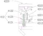
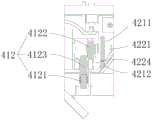
具体的,结合图2所示,驱动机构400包括设置在手柄本体100 内的驱动模块410,驱动模块410包括动力轴4111、动力源411以 及电源组件413,动力源411用于驱动动力轴4111转动,导管200 通过连接模块440可拆卸连接于动力轴4111。其中,动力源411为 电机,电机用于驱动扭矩轴210转动,电源组件413为电性连接于 电机的电池。Specifically, as shown in FIG. 2 , the
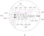
其中,结合图31至图33所示,扭矩轴210的近端设置有传动 轴212,动力轴4111的远端设置有插接槽4112,传动轴212插接在 插接槽4112内且与动力轴4111同步转动。传动轴212上设置有卡 接槽2121,连接模块440包括与卡接槽2121卡合连接的卡接定位组 件441以及用于控制卡接定位组件441的卡接控制组件442。Wherein, as shown in FIG. 31 to FIG. 33 , the proximal end of the
在本实施例中,扭矩轴210具体包括轴本体213以及设置在轴 本体213上的绕簧214,其中,绕簧214呈螺旋状缠绕并固定在轴本 体213上,可通过焊接固定,绕簧214的旋转方向与轴本体213的 旋转方向相反。当电机驱动扭矩轴210旋转时,与轴本体213旋转 方向相反的绕簧214能够更迅速的将导管200中的斑块送出,提高 切除效率。In this embodiment, the
进一步地,传动轴212上设置有至少一个限位块2122,插接槽 4112的内壁上设置有限位槽4113,在传动轴212插接在插接槽4112 内以后,限位块2122用于与限位槽4113适配以将传动轴212周向 固定于动力轴4111。在本实施例中,传动轴212上设置有三个圆周阵列分布的限位块2122,三个限位块2122通过与限位槽4113插接 形式配合,起到使动力轴4111和传动轴212圆周方向同步转动的作 用,以使扭矩轴210与动力轴4111同步转动。Further, the
进一步地,卡接定位组件441包括卡接件4411、定位件4412 以及连接端部4413,卡接件4411设置在动力轴4111上并用于与卡 接槽2121卡合连接,定位件4412活动连接于动力轴4111,定位件 4412用于卡接件4411的定位,连接端部4413用于连接卡接控制件 443以及卡接件4411,卡接控制组件442通过控制连接端部4413以 控制卡接件4411与卡接槽2121卡合连接或分离。Furthermore, the clamping and
当传动轴212插入至插接槽4112的底部时,卡接件4411的头 端卡合连接于卡接槽2121,由于卡接件4411通过定位件4412与动 力轴4111轴向固定,因此当卡接件4411与卡接槽2121卡合连接时, 限制了传动轴212与动力轴4111的轴向位移。When the
在本实施例中,卡接件4411为头端朝向传动轴212弯曲的卡位 弹片,定位件4412为螺纹连接于动力轴4111的固定螺栓。卡接件 4411上设置有用于定位件4412穿过的通孔,通过将定位件4412穿 过卡接件4411上的通孔并螺纹连接于动力轴4111,以使卡接件4411轴向固定与动力轴4111,并且卡接件4411能够以定位件4412为中 心点转动,从而卡合连接于卡接槽2121或者从卡接槽2121内脱离。In this embodiment, the engaging
连接端部4413一体成型于卡接件4411,连接端部4413设置在 卡接件4411的尾端,连接端部4413为驱动弹片,且驱动弹片朝向 背离动力轴4111的方向弯曲。当朝向动力轴4111的方向挤压连接 端部4413时,卡接件4411以定位件4412为中点转动,从而卡接件4411的头端从而卡接槽2121内脱离,使动力轴4111与传动轴212 可沿轴向分离。The connecting
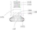
卡接控制组件442包括设置在手柄本体100上轴套4421、固定 设置在轴套4421内侧的固定端部4422、与轴套4421活动连接的活 动端部4423以及卡接控制件443,活动端部4423设置定位件4412 与连接端部4413之间,卡接控制件443用于控制活动端部4423移 动,动力轴4111穿过固定端部4422以及活动端部4423后连接件于 传动轴212。The snap-in
固定端部4422为与动力轴4111连接的固定轴承,活动端部4423 为沿轴套4421的轴向方向与轴套4421滑动连接的滑动压块。卡接 控制件443包括连接于固定端部4422与活动端部4423的弹性件 4433以及用于控制滑动压块位置的拉绳4431。The
拉绳4431的末端设置有拉环4432,连接端部4413与卡接件4411 一体连接,连接端部4413的近端翘起,活动端部4423在连接端部 4413与卡接件4411之间滑移。The end of the
具体的,固定端部4422固定连接于轴套4421的内侧,并连接 于动力轴4111,动力轴4111以定位件4412为基点转动。活动端部 4423与定位件4412之间设置有弹性件4433,弹性件4433用于驱动 活动端部4423朝向远离定位件4412的方向滑移,弹性件4433靠近 活动端部4423的一端或者活动端部4423上设置有拉绳4431,拉绳 4431的一端连接于弹性件4433或者活动端部4423,拉绳4431的另 一端连接于手柄本体100外侧的拉环4432,操作者可以通过拉环 4432牵拉拉绳4431,以使活动端部4423朝向固定端部4422的方向 移动。其中,弹性件4433为弹簧,拉绳4431为镍钛丝,镍钛丝焊 接在弹簧上。Specifically, the
在初始状态时,活动端部4423在弹性件4433的作用力下,位 于远离固定轴承的一侧,此时活动端部4423位于卡接件4411上, 卡接件4411的头端卡合连接在卡接槽2121内。当操作者通过牵拉 拉绳4431时,活动端部4423沿轴套4421的轴向方向朝向固定端部 4422移动,并从两侧挤压连接端部4413,使得连接端部4413朝向 动力轴4111的方向移动,并使卡接件4411以定位件4412为中点转 动,从而卡接件4411的头端脱离卡接槽2121,此时,动力轴4111 与传动轴212可以轴向分离。In the initial state, the
由上,本实施例通过设置卡接定位组件441和卡接控制组件 442,使得扭矩轴210可以轴向可拆卸连接于动力轴4111,并通过限 位块2122和限位槽4113的配合,使扭矩轴210与动力轴4111同轴 转动,电机输出扭矩并通过动力轴4111驱动扭矩轴210转动。Based on the above, this embodiment provides the clamping
手柄本体100上设置有收集部170,收集部170罩设在导管200 近端的外侧,收集部170用于收集从导管200中排出的斑块。并且 收集部170与手柄本体100可拆卸连接,导管200的近端与收集部 170可拆卸连接。导管200的近端设置有缓冲套管270,缓冲套管270 上设置有密封槽271,手柄本体100与收集部170分别通过密封槽 271与导管200连接。The
在本实施例中,收集部170设置在手柄本体100远端的底部, 收集部170与手柄本体100之间设置有收集腔体,通过收集腔体容 纳切除的斑块。导管200的近端固定连接于缓冲导管200的远端, 或者导管200的近端固定连接于缓冲导管200的近端。扭矩轴210 依次穿过导管200以及缓冲导管200并伸入收集部170内,由导管 200冲排出的斑块或者血栓掉落在收集部170内。In this embodiment, the
轴套4421固定连接于手柄本体100且朝向收集部170的方向突 出,卡接控制组件442的其它部件均设置在轴套4421的内腔中。动 力轴4111的一端连接于动力源411,且动力轴4111的另一端穿出轴 套4421并与传动轴212连接。The
由于导管200的近端连接于缓冲套管270,因此导管200中的斑 块或者血栓在通过缓冲套管270以后就会因扭矩轴210的高速旋转 和自身重力落入收集部170内,而不会跟随扭矩轴210继续向前移 动。从而保护了设置在轴套4421内的卡接控制组件442。Since the proximal end of the
进一步地,如图30所示,本实施例的轴本体213的长度大于绕 簧214的长度,且绕簧214近端与传动轴212之间的设置有间隔段, 位于间隔段的轴本体213上未设置绕簧214。通过上述方案,由导管 200中排出的斑块或者血栓移动至绕簧214的近端后,就会因扭矩轴210的高速旋转和自身重力落入收集部170内,从而保证了斑块或者 血栓不会继续向前移动,而对卡接控制组件442造成影响。Further, as shown in Figure 30, the length of the
具体的,缓冲套管270固定设置在导管200上,缓冲套管270 为硅胶材质,缓冲套管270上设置有密封槽271,密封槽271绕缓冲 套管270的一周向缓冲套管270内部凹陷,形成一圈环形的凹槽, 缓冲套管270与手柄本体100和收集部170组合后,手柄本体100 和收集部170的边缘通过缓冲槽连接从而密封。Specifically, the
通过本实施例的上述技术方案,医生可以根据实际使用情况更 换导管200。具体操作时,首先将收集部170取下,然后拉动手柄本 体100上的拉环4432,通过拉环4432将拉力沿着拉绳4431传递到 弹性件4433上,以使活动端部4423朝向固定端部4422移动。在活动端部4423移动的过程中,活动端部4423逐渐压过连接端部4413, 使翘起的连接端部4413朝向动力轴4111移动。在连接端部4413的 联动作用下,嵌入卡接槽2121的卡接件4411逐渐从卡接槽2121中 脱离。当卡接件4411整体从卡接槽2121内脱离时,操作者可以沿 轴向将扭矩轴210从而动力轴4111上拆卸。Through the above-mentioned technical solution of this embodiment, the doctor can replace the
在装入新的扭矩轴210时,首先牵拉拉环4432,然后将扭矩轴 210插入插接槽4112中,然后放开拉环4432,确认卡接件4411卡 入卡接槽2121后,将收集部170安装在手柄本体100上。When installing a
本实施例采用了可更换导管200的设计,提高了手术的灵活性 和经济性,避免了因导管200的堵塞导致斑块或者血栓无法及时排 出血管,而造成远端栓塞,保证了病人的生命安全。This embodiment adopts the design of
以上,仅为本发明较佳的具体实施方式,但本发明的保护范围 并不局限于此,任何熟悉本技术领域的技术人员在本发明揭露的技 术范围内,可轻易想到的变化或替换,都应涵盖在本发明的保护范 围之内。因此,本发明的保护范围应以权利要求的保护范围为准。The above is only a preferred embodiment of the present invention, but the scope of protection of the present invention is not limited thereto. Anyone skilled in the art can easily think of changes or substitutions within the technical scope disclosed in the present invention. All should be covered within the protection scope of the present invention. Therefore, the protection scope of the present invention should be based on the protection scope of the claims.
Claims (10)
Priority Applications (4)
| Application Number | Priority Date | Filing Date | Title |
|---|---|---|---|
| CN202111678798.1ACN116407225A (en) | 2021-12-31 | 2021-12-31 | a cutting device |
| US18/724,570US20250099129A1 (en) | 2021-12-31 | 2022-12-27 | Resection Apparatus |
| PCT/CN2022/142344WO2023125539A1 (en) | 2021-12-31 | 2022-12-27 | Resection apparatus |
| EP22914792.1AEP4458289A4 (en) | 2021-12-31 | 2022-12-27 | Resection apparatus |
Applications Claiming Priority (1)
| Application Number | Priority Date | Filing Date | Title |
|---|---|---|---|
| CN202111678798.1ACN116407225A (en) | 2021-12-31 | 2021-12-31 | a cutting device |
Publications (1)
| Publication Number | Publication Date |
|---|---|
| CN116407225Atrue CN116407225A (en) | 2023-07-11 |
Family
ID=87050156
Family Applications (1)
| Application Number | Title | Priority Date | Filing Date |
|---|---|---|---|
| CN202111678798.1APendingCN116407225A (en) | 2021-12-31 | 2021-12-31 | a cutting device |
Country Status (1)
| Country | Link |
|---|---|
| CN (1) | CN116407225A (en) |
Citations (6)
| Publication number | Priority date | Publication date | Assignee | Title |
|---|---|---|---|---|
| US20070010841A1 (en)* | 2005-07-05 | 2007-01-11 | Medical Innovations Pte Ltd | Lancet assembly |
| CN202020777U (en)* | 2011-03-31 | 2011-11-02 | 先健科技(深圳)有限公司 | Adjustable bent catheter |
| US20120239142A1 (en)* | 2011-02-25 | 2012-09-20 | Jun Liu | Prosthetic heart valve delivery apparatus |
| CN103957825A (en)* | 2011-10-13 | 2014-07-30 | 阿瑟罗迈德公司 | Atherectomy apparatus, systems and methods |
| US20200129202A1 (en)* | 2018-10-29 | 2020-04-30 | Cardiovascular Systems, Inc. | System, device, and method for interrupted dual action (sanding and cutting) forces with continual maceration and aspiration |
| CN214857236U (en)* | 2021-03-02 | 2021-11-26 | 上海交通大学医学院附属瑞金医院 | Disposable scalpel blade with protective sheath |
- 2021
- 2021-12-31CNCN202111678798.1Apatent/CN116407225A/enactivePending
Patent Citations (6)
| Publication number | Priority date | Publication date | Assignee | Title |
|---|---|---|---|---|
| US20070010841A1 (en)* | 2005-07-05 | 2007-01-11 | Medical Innovations Pte Ltd | Lancet assembly |
| US20120239142A1 (en)* | 2011-02-25 | 2012-09-20 | Jun Liu | Prosthetic heart valve delivery apparatus |
| CN202020777U (en)* | 2011-03-31 | 2011-11-02 | 先健科技(深圳)有限公司 | Adjustable bent catheter |
| CN103957825A (en)* | 2011-10-13 | 2014-07-30 | 阿瑟罗迈德公司 | Atherectomy apparatus, systems and methods |
| US20200129202A1 (en)* | 2018-10-29 | 2020-04-30 | Cardiovascular Systems, Inc. | System, device, and method for interrupted dual action (sanding and cutting) forces with continual maceration and aspiration |
| CN214857236U (en)* | 2021-03-02 | 2021-11-26 | 上海交通大学医学院附属瑞金医院 | Disposable scalpel blade with protective sheath |
Similar Documents
| Publication | Publication Date | Title |
|---|---|---|
| CN111163717B (en) | Polypectomy systems, devices, and methods | |
| EP2617372B1 (en) | Material removal device | |
| JP2002522105A5 (en) | ||
| CN115089269B (en) | Rotary cutting type blood vessel volume reduction equipment | |
| CN111884419B (en) | Driving device | |
| CN205885497U (en) | Ultrasonic knife head with centre gripping arm drive assembly | |
| AU2013245525A1 (en) | Material removal device and method of use | |
| WO2023125539A1 (en) | Resection apparatus | |
| CN116407222A (en) | a cutting device | |
| CN116407223A (en) | Excision device | |
| CN116407225A (en) | a cutting device | |
| CN116407224A (en) | a cutting device | |
| CN116407221A (en) | Excision device | |
| CN116407218A (en) | Excision device | |
| CN220025115U (en) | Plugging device convenient to operate | |
| CN115624372B (en) | Surgical instrument | |
| CN116549064A (en) | Rotary cutting device and application method thereof | |
| CN221949889U (en) | Ablation system | |
| CN111870320A (en) | Surgical instrument | |
| CN116269657A (en) | Retroperitoneal fat removal device | |
| CN221671873U (en) | A simple gynecological surgical planer | |
| CN120227126A (en) | Resection device | |
| US10117663B2 (en) | Coring tool | |
| CN120227125A (en) | Resection system | |
| CN116439771A (en) | An easy-to-operate occluder |
Legal Events
| Date | Code | Title | Description |
|---|---|---|---|
| PB01 | Publication | ||
| PB01 | Publication | ||
| SE01 | Entry into force of request for substantive examination | ||
| SE01 | Entry into force of request for substantive examination |