CN116407201A - Clamping chamber and clamp applicator - Google Patents
Clamping chamber and clamp applicatorDownload PDFInfo
- Publication number
- CN116407201A CN116407201ACN202111670812.3ACN202111670812ACN116407201ACN 116407201 ACN116407201 ACN 116407201ACN 202111670812 ACN202111670812 ACN 202111670812ACN 116407201 ACN116407201 ACN 116407201A
- Authority
- CN
- China
- Prior art keywords
- clip
- cavity
- along
- bin
- assembly
- Prior art date
- Legal status (The legal status is an assumption and is not a legal conclusion. Google has not performed a legal analysis and makes no representation as to the accuracy of the status listed.)
- Pending
Links
Images


Classifications
- A—HUMAN NECESSITIES
- A61—MEDICAL OR VETERINARY SCIENCE; HYGIENE
- A61B—DIAGNOSIS; SURGERY; IDENTIFICATION
- A61B17/00—Surgical instruments, devices or methods
- A61B17/12—Surgical instruments, devices or methods for ligaturing or otherwise compressing tubular parts of the body, e.g. blood vessels or umbilical cord
- A61B17/128—Surgical instruments, devices or methods for ligaturing or otherwise compressing tubular parts of the body, e.g. blood vessels or umbilical cord for applying or removing clamps or clips
- A—HUMAN NECESSITIES
- A61—MEDICAL OR VETERINARY SCIENCE; HYGIENE
- A61B—DIAGNOSIS; SURGERY; IDENTIFICATION
- A61B17/00—Surgical instruments, devices or methods
- A61B17/12—Surgical instruments, devices or methods for ligaturing or otherwise compressing tubular parts of the body, e.g. blood vessels or umbilical cord
- A61B17/122—Clamps or clips, e.g. for the umbilical cord
- A61B17/1222—Packages or dispensers therefor
- A—HUMAN NECESSITIES
- A61—MEDICAL OR VETERINARY SCIENCE; HYGIENE
- A61B—DIAGNOSIS; SURGERY; IDENTIFICATION
- A61B17/00—Surgical instruments, devices or methods
- A61B17/08—Wound clamps or clips, i.e. not or only partly penetrating the tissue ; Devices for bringing together the edges of a wound
- A—HUMAN NECESSITIES
- A61—MEDICAL OR VETERINARY SCIENCE; HYGIENE
- A61B—DIAGNOSIS; SURGERY; IDENTIFICATION
- A61B17/00—Surgical instruments, devices or methods
- A61B17/08—Wound clamps or clips, i.e. not or only partly penetrating the tissue ; Devices for bringing together the edges of a wound
- A61B17/083—Clips, e.g. resilient
- A—HUMAN NECESSITIES
- A61—MEDICAL OR VETERINARY SCIENCE; HYGIENE
- A61B—DIAGNOSIS; SURGERY; IDENTIFICATION
- A61B17/00—Surgical instruments, devices or methods
- A61B17/12—Surgical instruments, devices or methods for ligaturing or otherwise compressing tubular parts of the body, e.g. blood vessels or umbilical cord
- A61B17/122—Clamps or clips, e.g. for the umbilical cord
- A61B17/1227—Spring clips
- A—HUMAN NECESSITIES
- A61—MEDICAL OR VETERINARY SCIENCE; HYGIENE
- A61B—DIAGNOSIS; SURGERY; IDENTIFICATION
- A61B17/00—Surgical instruments, devices or methods
- A61B17/12—Surgical instruments, devices or methods for ligaturing or otherwise compressing tubular parts of the body, e.g. blood vessels or umbilical cord
- A61B17/128—Surgical instruments, devices or methods for ligaturing or otherwise compressing tubular parts of the body, e.g. blood vessels or umbilical cord for applying or removing clamps or clips
- A61B17/1285—Surgical instruments, devices or methods for ligaturing or otherwise compressing tubular parts of the body, e.g. blood vessels or umbilical cord for applying or removing clamps or clips for minimally invasive surgery
Landscapes
- Health & Medical Sciences (AREA)
- Surgery (AREA)
- Life Sciences & Earth Sciences (AREA)
- Heart & Thoracic Surgery (AREA)
- Nuclear Medicine, Radiotherapy & Molecular Imaging (AREA)
- Engineering & Computer Science (AREA)
- Biomedical Technology (AREA)
- Medical Informatics (AREA)
- Molecular Biology (AREA)
- Animal Behavior & Ethology (AREA)
- General Health & Medical Sciences (AREA)
- Public Health (AREA)
- Veterinary Medicine (AREA)
- Vascular Medicine (AREA)
- Reproductive Health (AREA)
- Surgical Instruments (AREA)
Abstract
Description
Translated fromChinese技术领域technical field
本发明涉及医疗器械技术领域,特别是涉及一种夹仓及施夹钳。The invention relates to the technical field of medical instruments, in particular to a clip bin and a clip applier.
背景技术Background technique
施夹钳包括操作组件、自操作组件延伸的杆身组件和设置于杆身组件远端的钳口组件。在杆身组件中设有夹仓,用以放置夹子,为了实现连续施夹,夹仓中往往会放置多个夹子。在施夹时,通过操作施夹钳的操作组件,将夹仓内的夹子推至钳口组件中,再闭合钳口组件,使位于钳口组件中的夹子夹持于组织或血管上,从而起到止血、结扎闭合的作用。The clip applier includes an operating component, a shaft component extending from the operating component, and a jaw component arranged at the distal end of the shaft component. A clip chamber is provided in the shaft assembly for placing clips. In order to realize continuous clip application, multiple clips are often placed in the clip chamber. When clipping, by operating the operating assembly of the clip applier, the clip in the clip chamber is pushed into the jaw assembly, and then the jaw assembly is closed, so that the clip located in the jaw assembly is clamped on the tissue or blood vessel, thereby Play the role of hemostasis, ligation and closure.
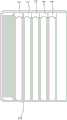
参考图17,现有技术中的一种夹仓,夹子1在夹仓2内堆叠排布,夹子1之间无错位。此夹仓2仅适用于夹臂上无凸部的夹子1。参考图6,本发明中的夹子1包括夹臂,夹臂上具有凸部,若将图6示出的夹子按照图17中的放置方法进行排布,十分占用空间,并且夹子难以稳定放置于夹仓内。Referring to FIG. 17 , a clip magazine in the prior art, the
基于上述,有必要对现有技术中的夹仓进行改进。Based on the above, it is necessary to improve the clip bin in the prior art.
发明内容Contents of the invention
针对现有技术的不足,本发明旨在提供一种夹仓及施夹钳,解决了夹仓占用空间大,夹子放置在夹仓内的稳定性差的技术问题。Aiming at the deficiencies of the prior art, the present invention aims to provide a clip chamber and a clip applier, which solves the technical problems of large space occupied by the clip chamber and poor stability of clips placed in the clip chamber.
本发明通过以下技术方案实现:The present invention is realized through the following technical solutions:
一种夹仓,其包括至少两个夹子,所述夹子包括夹臂,所述夹臂具有凸部,其特征在于,所述夹仓还包括:A clip bin, which includes at least two clips, the clip includes a clip arm, the clip arm has a convex portion, characterized in that the clip bin further includes:
夹仓本体,所述夹仓本体具有夹腔以容置所述夹子;至少两个所述夹子沿第一方向错位堆叠,以使相邻的所述夹子的所述凸部沿所述第一方向错位;每个所述夹子均大致沿第二方向设置。A clip body, the clip body has a clip cavity for accommodating the clip; at least two clips are staggered and stacked along the first direction, so that the protrusions of the adjacent clips are stacked along the first direction Directional misalignment; each of said clips is disposed generally along a second direction.
进一步,每个所述夹臂沿所述第一方向具有相对的两个侧壁,至少一个所述侧壁上具有所述凸部。Further, each clamping arm has two opposite side walls along the first direction, and at least one of the side walls has the protrusion.
进一步,所述夹仓还包括偏置组件,所述偏置组件设置于所述夹仓本体;所述偏置组件对于所述夹子施加大致沿所述第一方向的作用力。Further, the clip cartridge further includes a biasing component, the biasing component is arranged on the clip cartridge body; the biasing component exerts a force on the clip generally along the first direction.
更进一步,所述夹腔包括第一腔体和第二腔体,所述第一腔体和所述第二腔体沿所述第一方向依次设置;在初始状态下,所述第一腔体和所述第二腔体均容置有所述夹子。Furthermore, the clamping cavity includes a first cavity and a second cavity, and the first cavity and the second cavity are sequentially arranged along the first direction; in an initial state, the first cavity Both the body and the second cavity accommodate the clip.
更进一步,所述偏置组件包括弹性件。Furthermore, the biasing assembly includes an elastic member.
更进一步,所述偏置组件与沿所述第一方向正向的第一个所述夹子相抵。Furthermore, the biasing assembly abuts against the first clip that is positive along the first direction.
更进一步,所述夹臂沿所述第一方向具有相对的两个侧壁,至少一个所述侧壁上设置有所述凸部,所述夹子包括第一端部和第二端部,所述凸部靠近所述第一端部且远离所述第二端部,所述第一腔体内设置有限位斜面,所述限位斜面与所述第一腔体内的所述夹子的所述第二端部抵接。Further, the clip arm has two opposite side walls along the first direction, at least one of the side walls is provided with the protrusion, the clip includes a first end and a second end, so The convex portion is close to the first end and away from the second end, and a limiting slope is arranged in the first cavity, and the limiting slope is connected with the first clamp of the clip in the first cavity. The two ends are butted.
更进一步,所述夹臂沿所述第一方向具有相对的两个侧壁,至少一个所述侧壁上设置有所述凸部;所述第二腔体中具有沿第二方向延伸的凹槽,位于所述第二腔体中的所述夹子的所述凸部容置于所述凹槽。Furthermore, the clip arm has two opposite side walls along the first direction, at least one of the side walls is provided with the protrusion; the second cavity has a concave extending along the second direction. A groove, the protrusion of the clip located in the second cavity is accommodated in the groove.
更进一步,所述夹仓沿第二方向具有相对的第一端和第二端,所述第二腔体沿所述第二方向延伸,所述第二腔体在所述夹仓的所述第一端形成第一开口,所述第二腔体在所述夹仓的所述第二端形成第二开口。Furthermore, the cartridge has opposite first and second ends along a second direction, the second cavity extends along the second direction, and the second cavity is located on the side of the cartridge. The first end forms a first opening and the second cavity forms a second opening at the second end of the cartridge.
更进一步,所述夹仓本体包括限位件,所述限位件设置于所述夹仓本体的侧壁,所述限位件与位于所述第二腔体内的所述夹子相抵接,响应于施加于所述夹子的沿所述第二方向的作用力,所述夹子与所述限位件脱离并从所述第一开口处脱离所述第二腔体。Furthermore, the clip body includes a limiter, the limiter is arranged on the side wall of the clip body, the limiter abuts against the clip located in the second cavity, and responds to When an active force along the second direction is applied to the clip, the clip is disengaged from the limiting member and disengaged from the second cavity from the first opening.
本发明同时提供一种施夹钳,所述施夹钳包括操作组件、杆身组件和钳口组件,所述杆身组件自所述操作组件延伸,所述钳口组件设置于所述杆身组件的远端,其特征在于,所述施夹钳还包括所述的夹仓,所述夹仓设置于所述杆身组件。The present invention also provides a clip applier, the clip applier includes an operating assembly, a shaft assembly and a jaw assembly, the shaft assembly extends from the operating assembly, and the jaw assembly is arranged on the shaft The distal end of the assembly is characterized in that the clip applier also includes the clip bin, and the clip bin is arranged on the shaft assembly.
进一步,所述夹仓与所述杆身组件通过卡扣结构连接。Further, the clip bin is connected to the shaft assembly through a buckle structure.
与现有技术相比,本发明的有益效果在于:本发明的夹仓通过将夹子错位堆叠,能够节约空间,使得夹仓的占用空间小,相邻夹子的凸部能够相互避让,使夹子能稳定的堆叠于夹仓内。Compared with the prior art, the beneficial effect of the present invention is that: the clip bin of the present invention can save space by dislocation stacking the clips, so that the occupied space of the clip bin is small, and the convex parts of adjacent clips can avoid each other, so that the clips can Stable stacked in the clip compartment.
附图说明Description of drawings
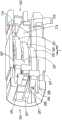
图1是本发明具体实施方式提供的夹仓的第一角度的结构示意图;Fig. 1 is a structural schematic diagram of a first angle of a clip bin provided in a specific embodiment of the present invention;
图2是本发明具体实施方式提供的夹仓的第二角度的结构示意图;Fig. 2 is a schematic structural view of the second angle of the clip bin provided by the specific embodiment of the present invention;
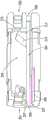
图3是本发明具体实施方式提供的夹仓的第三角度的结构示意图,其中,第一侧部未显示;Fig. 3 is a schematic structural diagram of a third angle of the clip bin provided by a specific embodiment of the present invention, wherein the first side part is not shown;
图4是本发明具体实施方式提供的夹仓的第四角度的结构示意图,其中,第一侧部以和偏置组件均未显示;Fig. 4 is a structural schematic diagram of a fourth angle of the clip bin provided by a specific embodiment of the present invention, wherein neither the first side nor the biasing assembly is shown;
图5是本发明具体实施方式提供的夹仓本体的结构示意图,其中,第一侧部未显示;Fig. 5 is a schematic structural view of the clip body provided by a specific embodiment of the present invention, wherein the first side part is not shown;
图6是本发明具体实施方式提供的夹子的结构示意图;Fig. 6 is a schematic structural view of a clip provided in a specific embodiment of the present invention;
图7是本发明具体实施方式提供的夹子在夹仓本体的堆叠示意图;Fig. 7 is a schematic diagram of the stacking of the clips provided in the specific embodiment of the present invention on the clip body;
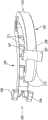
图8是本发明具体实施方式提供的偏置组件的结构示意图;Fig. 8 is a schematic structural diagram of a bias assembly provided by a specific embodiment of the present invention;
图9是本发明具体实施方式提供的夹仓的第五角度的结构示意图,其中,第一侧部未显示;Fig. 9 is a schematic structural view of the fifth angle of the clip bin provided by the specific embodiment of the present invention, wherein the first side part is not shown;
图10是本发明具体实施方式提供的夹仓的第一侧部的结构示意图;Fig. 10 is a schematic structural view of the first side of the clip provided by the specific embodiment of the present invention;
图11是本发明具体实施方式提供的第一侧部与夹子的配合方式示意图;Fig. 11 is a schematic diagram of the cooperation mode between the first side part and the clip provided by the specific embodiment of the present invention;
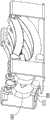
图12是本发明具体实施方式提供的施夹钳的第一角度的结构示意图;Fig. 12 is a schematic structural view of the first angle of the clip applier provided by the specific embodiment of the present invention;
图13是本发明具体实施方式提供的施夹钳的第二角度的结构示意图;Fig. 13 is a schematic structural view of the second angle of the clip applier provided by the specific embodiment of the present invention;
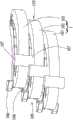
图14是本发明具体实施方式提供的施夹钳的部分区域的结构示意图,其中,套管未显示;Fig. 14 is a schematic structural view of a partial region of the clip applier provided by a specific embodiment of the present invention, wherein the sleeve is not shown;
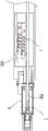
图15是本发明具体实施方式提供的施夹钳的部分区域的剖面图,其中,送夹杆处于初始状态;Fig. 15 is a cross-sectional view of a partial area of the clamp applier provided by a specific embodiment of the present invention, wherein the clamping rod is in an initial state;
图16是本发明具体实施方式提供的施夹钳的部分区域的剖面图,其中,送夹杆已将夹子送至钳口组件中;Fig. 16 is a cross-sectional view of a partial area of the clip applier provided by a specific embodiment of the present invention, wherein the clip feeding rod has sent the clip to the jaw assembly;
图17是现有技术中夹仓的结构示意图;Fig. 17 is a schematic structural view of the folder in the prior art;
图18是本发明具体实施方式提供的夹仓本体的剖面图;Fig. 18 is a cross-sectional view of the clip body provided by the specific embodiment of the present invention;
图19是本发明具体实施方式提供的施夹钳的主轴的部分区域的结构示意图;Fig. 19 is a schematic structural view of a partial area of the main shaft of the clip applier provided in a specific embodiment of the present invention;
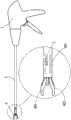
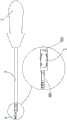
图20是本发明另一个实施方式提供的施夹钳的部分区域的结构示意图。Fig. 20 is a schematic structural view of a partial region of a clip applier provided by another embodiment of the present invention.
以上附图的附图标记:1-夹子;101-夹子;102-夹子;103-夹子;104-第一夹臂;105-第二夹臂;106-第一凸部;107-第二凸部;108-凸块;109-第一端部;110-第二端部;111-上侧壁;112-下侧壁;2-夹仓;201-第一端;202-第二端;203-第一腔体;204-第二腔体;205-第一开口;206-第二开口;207-第一凹槽;208-第二凹槽;209-第一公卡扣;210-第二公卡扣;209-第一侧部; 2091-第一安装部;2092-第二安装部;2093-第三安装部;210-第二侧部;211-第三侧部;212-第四侧部;213-限位件;214-限位斜面;215-安装块;216-凹陷部;217-安装槽;218-弹性件;2181-第一扭臂;2182-第二扭臂;2183-螺旋本体;219-推板; 3-杆身组件;301-主轴;3011-通道;3012-第一母卡扣;3013-第二母卡扣;3014-第一轴部;3015-第二轴部;302-送夹杆;303-套管;3031第一管体;3032-第二管体;4-钳口组件;401-第一钳臂;402-第二钳臂;403-弹簧;5-操作组件;6-枢转件;7-转动关节。Reference signs of the above drawings: 1-clip; 101-clip; 102-clip; 103-clip; 104-first clamp arm; 105-second clamp arm; 106-first convex part; 107-second convex 108-bump; 109-first end; 110-second end; 111-upper sidewall; 112-lower sidewall; 2-clamp bin; 201-first end; 202-second end; 203-first cavity; 204-second cavity; 205-first opening; 206-second opening; 207-first groove; 208-second groove; 209-first male buckle; 210- 209-first side; 2091-first installation; 2092-second installation; 2093-third installation; 210-second side; 211-third side; 212- Fourth side; 213-limiting piece; 214-limiting slope; 215-installation block; 216-depression; 217-installation groove; 218-elastic piece; ;2183-Screw body; 219-Push plate; 3-Shaft assembly; 301-Spindle; 3011-Channel; 3012-First female buckle; 3013-Second female buckle; 302-feed clamp rod; 303-sleeve; 3031 first pipe body; 3032-second pipe body; 4-jaw assembly; 401-first pliers arm; 402-second pliers arm; 403 - spring; 5 - operating assembly; 6 - pivot; 7 - swivel joint.
具体实施方式Detailed ways
为了使本发明的目的、技术方案及优点更加清楚明白,以下结合附图及实施例,对本发明进行进一步详细说明。应当理解,此处所描述的具体实施例仅用以解释本发明,并不用于限定本发明。基于本发明中的实施例,本领域普通技术人员在没有做出创造性劳动前提下所获得的所有其他实施例,都属于本发明保护的范围。In order to make the object, technical solution and advantages of the present invention clearer, the present invention will be further described in detail below in conjunction with the accompanying drawings and embodiments. It should be understood that the specific embodiments described here are only used to explain the present invention, not to limit the present invention. Based on the embodiments of the present invention, all other embodiments obtained by persons of ordinary skill in the art without making creative efforts belong to the protection scope of the present invention.
需要理解的是,本文所用术语“近”、“后”和“远”、“前”是相对于操纵施夹钳的操作组件的临床医生而言的。术语“近”、“后”是指靠近临床医生的部分,术语“远”、“前”则是指远离临床医生的部分。即操作组件为近端,钳口组件为远端,如某个零部件的近端表示相对靠近操作组件的一端,远端则表示相对靠近钳口组件的一端。然而,施夹钳可以在许多方向和位置使用,因此这些表达相对位置关系的术语并不是受限和绝对的。It should be understood that the terms "proximal", "rear" and "distal", "anterior" as used herein are relative to the clinician manipulating the operative components of the clip applier. The terms "proximal" and "posterior" refer to the part close to the clinician, and the terms "distal" and "anterior" refer to the part away from the clinician. That is, the operating component is the proximal end, and the jaw component is the distal end. For example, the proximal end of a component means the end relatively close to the operating component, and the far end means the end relatively close to the jaw component. However, the clip applier can be used in many orientations and positions, so these terms expressing relative positional relationships are not limiting and absolute.
在本发明中,除非另有明确的规定和限定,“相连”、“连接”等术语应做广义理解,例如,可以是固定连接,也可以是可拆卸地连接,还可以是可运动地连接,或成一体;可以是直接相连,也可以通过中间媒介间接相连,可以是两个元件内部的连通或两个元件的相互作用关系如抵接。对于本领域的普通技术人员而言,可以根据具体情况理解上述术语在本发明中的具体含义。需要说明的是,在“相连”、“连接”前有限定语时,其具有相应限定语所限定的含义,只排除明显需要排除的情形,不排除其它可能的情形。In the present invention, terms such as "connected" and "connected" should be interpreted in a broad sense unless otherwise clearly specified and limited, for example, they can be fixedly connected, detachably connected, or movably connected. , or integrated; it can be directly connected or indirectly connected through an intermediary, it can be the internal communication of two elements or the interaction relationship between two elements such as butting. Those of ordinary skill in the art can understand the specific meanings of the above terms in the present invention according to specific situations. It should be noted that when there are qualifiers before "connected" and "connected", it has the meaning defined by the corresponding qualifiers, and only the situations that obviously need to be excluded are excluded, and other possible situations are not excluded.
以图1中夹仓2的放置方向和角度为参考,图1中夹仓2沿水平方向放置,第一方向为上、下方向(即竖直方向),且第一方向的正向为由上至下。第二方向为夹仓2的纵长方向即左、右方向,也即是水平方向。第三方向为垂直于纸面的方向,第一方向、第二方向和第三方向相互垂直。需要说明的是,以图1中夹仓2的放置方向和角度作为参考时,第三方向垂直于纸面,其他附图中夹仓2的放置方向和角度发生改变时,第三方向随着夹仓2的方向和角度发生改变。Taking the placement direction and angle of the
请参阅图1-4,本发明提供一种夹仓2,其包括至少两个夹子1。本发明夹子1为现有技术中常见的止血夹。夹子1包括夹臂,夹臂具有凸部。夹仓2包括夹仓本体,夹仓本体内具有夹腔以容置所述夹子1。至少两个夹子1沿第一方向错位堆叠,以使相邻的所述夹子的凸部沿第一方向错位(即不重叠)。每个夹子1均大致沿第二方向设置。通过将夹子1以堆叠的方式放置,能够节约空间,使得夹仓2的占用空间较小。通过将夹子1错位放置,使得相邻夹子的凸部能够相互避让,进一步使夹子占用空间减小,并且夹子1能够稳定的堆叠于夹仓2内而不会倾倒。Referring to FIGS. 1-4 , the present invention provides a
参考图5,本实施例中,夹仓本体内的夹腔包括第一腔体203和第二腔体204,第一腔体203和第二腔体204沿第一方向依次设置,即第一腔体203设置于第二腔体204的上方。第一腔体203与第二腔体204连通。Referring to FIG. 5 , in this embodiment, the clip cavity in the clip body includes a
参考图4,夹仓2包括三个夹子1,由上至下依次为夹子101、夹子102和夹子103。在初始状态下,夹子101和夹子102设置于第一腔体203,夹子103设置于第二腔体204。夹子1的数量并不会影响夹仓2的正常使用,操作者也可根据具体的应用需求对夹子1的数量进行调整。Referring to FIG. 4 , the
参考图6,夹子1包括两个夹臂,即第一夹臂104和第二夹臂105。夹子1的第一夹臂104沿第一方向具有相对的上侧壁111和下侧壁112,第一夹臂104的上侧壁111具有一个第一凸部106,第一夹臂104的下侧壁112也具有一个第一凸部106。第二夹臂105沿第一方向具有相对的上侧壁111和下侧壁112,第二夹臂105的上侧壁111具有一个第二凸部107,第二夹臂105的下侧壁112也具有一个第二凸部107,两个第二凸部107通过凸块108相连接,具体而言,第二夹臂105上侧壁111的第二凸部107的下端与第二夹臂105下侧壁112的第二凸部107的上端通过凸块108相连接。本实施例中,两个第二凸部107与凸块108是一体的,以方便加工。其他实施方式中也可以省略中间凸块108。Referring to FIG. 6 , the
参考图5-7,夹仓2沿第二方向具有相对的第一端201和第二端202,需要说明的是,第一端201是一个区域而并非是一个端点,第二端202也是一个区域而并非是一个端点。夹子1沿第二方向具有相对的第一端部109和第二端部110,同样的,第一端部109是一个区域而并非是一个端点,第二端部110是一个区域而并非是一个端点。夹子1的第一端部109靠近夹仓2的第一端201设置,夹子1的第二端部110靠近夹仓2的第二端202设置。夹子1的每个第一凸部106和每个第二凸部107均靠近夹子1的第一端部109且远离夹子1的第二端部110。优选地,夹子1的每个第一凸部106均位于第一端部109。5-7, the
具体的,重点参考图3-4、7,夹子1在夹仓2内的堆叠方式为:Specifically, referring to Figures 3-4 and 7, the stacking method of the
夹子101下侧壁的第一凸部106和第二凸部107均与夹子102的上侧壁相抵接,夹子102上侧壁的第二凸部107与夹子101的下侧壁相抵接。更具体的,夹子101的第一夹臂104下侧壁的第一凸部106与夹子102的第一夹臂104上侧壁相抵接,夹子101的第二夹臂105下侧壁的第二凸部107与夹子102的第二夹臂105上侧壁相抵接。夹子102的第二夹臂105上侧壁的第二凸部107与夹子101的第二夹臂105下侧壁相抵接。Both the
夹子102下侧壁的第一凸部106和第二凸部107均与夹子103的上侧壁相抵接,夹子103上侧壁的第二凸部107与夹子102的下侧壁相抵接。更具体的,夹子102的第一夹臂104下侧壁的第一凸部106与夹子103的第一夹臂104上侧壁相抵接,夹子102的第二夹臂105下侧壁的第二凸部107与夹子103的第二夹臂105上侧壁相抵接。夹子103的第二夹臂105上侧壁的第二凸部107与夹子102的第二夹臂105下侧壁相抵接。Both the
综上,夹子101、夹子102、夹子103沿第一方向堆叠设置,由此能够节约空间,使得夹仓2的占用空间较小。夹子102的第一凸部106与夹子101的第一凸部106错位设置,夹子102的第二凸部107与夹子101的第二凸部107也错位设置。夹子103的第一凸部106与夹子102的第一凸部106错位设置,夹子103的第二凸部107与夹子102的第二凸部107也错位设置。并且,夹子102的第一凸部106与夹子101的第一凸部106在第一方向上不存在重叠部分,夹子102的第二凸部107与夹子101的第二凸部107在第一方向上也不存在重叠部分。夹子103的第一凸部106与夹子102的第一凸部106在第一方向上不存在重叠部分,夹子103的第二凸部107与夹子102的第二凸部107在第一方向上也不存在重叠部分,使得相邻凸部能够相互避让,进一步使夹子1占用空间减小,并且夹子1能够稳定的堆叠于夹仓2内而不会倾倒。To sum up, the
参考图3、8,夹仓2还包括偏置组件,偏置组件2设置于夹仓本体。具体的,偏置组件设置于夹仓本体的第一腔体203。偏置组件能够向夹子1施加大致沿第一方向的作用力,使得第一腔体203内的夹子1能够进入第二腔体204内,上述作用力还有助于夹子1被稳定地夹持于夹仓2内。Referring to Figures 3 and 8, the
具体的,偏置组件包括弹性件218和推板219。推板219与夹子101的上侧壁相抵接,推板219可为刚性的或者至少基本上刚性的。在弹性件218的作用下,推板219能够向夹子101施加沿第一方向的作用力。本实施例中,弹性件218选择扭簧。具体的,弹性件218包括第一扭臂2181、第二扭臂2182和螺旋本体2183。第一扭臂2181、第二扭臂2182和螺旋本体2183是一体的。参考图8,在无外力的作用下,弹性件218的第一扭臂2181和第二扭臂2182均处于自然舒展状态。Specifically, the bias assembly includes an
参考图3,在第一腔体203内设置有安装块215以用于安装弹性件218。弹性件218的设置位置不会影响其对夹子1的作用,由此,安装块215可以设置于第一腔体203的任何位置处。但为了节约空间并且便于第一腔体203内夹子1的排布,安装块215靠近夹仓2的第一端201或第二端202设置。本实施例中安装块215靠近夹仓2的第二端202设置。Referring to FIG. 3 , a mounting
安装块215具有与螺旋本体2183适配的凹陷部216,螺旋本体2183设置于凹陷部216。安装块215还设置有安装槽217,第一扭臂2181设置于安装槽217内,第二扭臂2182绕螺旋本体2183扭转一定角度后设置于夹子101的上侧并与推板219相连接,使得弹性件218发生形变,由此,第二扭臂2182能够通过推板219向夹子101施加大致沿第一方向的作用力。The mounting
参考图3-5,本实施例中,第二腔体204贯通夹仓本体设置。具体的,第二腔体204沿第二方向延伸,第二腔体204在夹仓2的第一端201形成第一开口205,第二腔体204在夹仓2的第二端202形成第二开口206。响应于施加于夹子103沿第二方向的作用力,夹子103从第一开口205处脱离夹仓2,偏置组件向下抵推夹子101和夹子102,使得夹子102进入第二腔体204内。当夹子102脱离夹仓2后,偏置组件再将夹子101抵推至第二腔体204内。Referring to FIGS. 3-5 , in this embodiment, the
再参考图3-4、7,夹子102的第一凸部106比夹子101的第一凸部106更靠近夹仓2的第一端201,夹子102的第二凸部107比夹子101的第二凸部107更靠近夹仓2的第一端201,由此,当夹子102向夹仓2的第一端201移动时,夹子101的第一凸部106和第二凸部107不会对夹子102的移动产生干涉。3-4,7 again, the first
夹子103的第一凸部106比夹子102的第一凸部106更靠近夹仓2的第一端201。夹子103的第二凸部107比夹子102的第二凸部107更靠近夹仓2的第一端201。由此,当夹子103向夹仓2的第一端201移动时,夹子102的第一凸部106和第二凸部107不会对夹子103的移动产生干涉。The
对于夹仓本体中的三个夹子1,其第一端部109沿第一方向并不是对齐的,夹子101的第一端部109最远离夹仓2的第一端201,夹子103的第一端部109最靠近夹仓2的第一端201。同样的,三个夹子1的第二端部110沿第一方向也并不是对齐的,夹子101的第二端部110最靠近夹仓2的第二端202,夹子103的第二端部110最远离夹仓2的第二端202。参考图3-5,在第一腔体203内设置有限位斜面214,限位斜面214与第一腔体203内的夹子1的第二端部110相抵接。由此,限位斜面214能够对第一腔体203内的夹子1进行支撑。即,夹子101的第一端部109支撑于夹子102上,具体的,夹子101的第一端部109通过其下侧壁的第一凸部106和第二凸部107支撑于夹子102上,夹子101的第二端部110支撑于限位斜面214。夹子102的第一端部109支撑于夹子103上,具体的,夹子102的第一端部109通过其下侧壁的第一凸部106和第二凸部107支撑于夹子103上,夹子102的第二端部110支撑于限位斜面214。本实施例中,优选地,限位斜面214设置于安装块215,由此,能够进一步节省空间,此时安装块215邻近夹仓2的第二端202设置。For the three
参考图1-2、图9,本实施例中夹仓本体沿第三方向具有相对的第一侧部209和第二侧部210。夹仓本体沿第一方向具有相对的第三侧部211和第四侧部212。参考图1-2、10-11,夹仓本体还包括限位件213,限位件213具有弹性。限位件213设置于夹仓本体的第一侧部209,且限位件213设置于第二腔体204。限位件213与位于第二腔体204内的夹子1相抵接。Referring to FIGS. 1-2 and 9 , the cartridge body in this embodiment has opposite
具体的,如前所述,夹子1的第二夹臂105上侧壁的第二凸部107的下端与其第二夹臂105下侧壁的第二凸部107的上端通过凸块108相连接。限位件213与位于第二腔体204内的夹子1的凸块108相抵接。响应于施加于夹子1的沿第二方向的作用力,第二腔体204内的夹子1的凸块108与限位件213脱离,夹子1从第一开口205处脱离第二腔体204。限位件213也可与夹子1的凸部107抵接进行限位。Specifically, as mentioned above, the lower end of the
本实施例中,通过设置偏置组件,使得夹子1能够被稳定的夹持于夹腔内。通过设置限位件213和限位斜面214,能够进一步对夹子1进行限位,使得夹子1更加稳定的置于夹腔内。具体的,参考图1-4、9-11,限位件213沿第二方向延伸,限位件213向夹腔内凹陷,使得限位件213大致沿第二方向向夹子103的凸块108施加朝向夹仓第二端202的力,夹子103上侧壁的第二凸部107与夹子102的下侧壁的第二凸部107大致沿第二方向相抵接,由于夹子102的上侧壁的第二凸部107与夹子101的下侧壁的第二凸部107大致沿第二方向相抵接,且夹子102的第二端部110与限位斜面214相抵接,夹子101的第二端部110也与限位斜面214相抵接,因此,夹子102能够配合限位件213共同对夹子103产生限位作用,同时夹子103配合限位斜面214对夹子102产生限位作用,夹子102配合限位斜面214对夹子101产生限位作用,由此,夹子101、夹子102和夹子103在第二方向上相互产生了限位作用,同时,夹子101的第一端部109支撑于夹子102上,夹子101的第二端部110支撑于限位斜面214。夹子102的第一端部109支撑于夹子103上,夹子102的第二端部110支撑于限位斜面214,并且偏置组件对夹子1施加大致沿第一方向的作用力,使夹子1能够被稳定的夹持于夹仓的夹腔内。夹子101能够大致沿第二方向设置。夹子102也能够大致沿第二方向设置,夹子102的第二端部110不会掉落至第二腔体204内,从而不会影响夹子103的使用,具体见后文描述。In this embodiment, the
再参考图1-2、图9,为了便于夹仓2内夹子1的安装,本实施例设置第一侧部209可与夹仓本体脱离,具体的,第一侧部209与夹仓本体可拆卸地连接。参考图10,第一侧部209的上端设置有两个卡接件,第一侧部209的下端也设置有两个卡接件。每一个卡接件包括第一安装部2091、第二安装部2092和第三安装部2093。参考图2,对于第一侧部209上端的每一个卡接件,其第一安装部2091设置于第三侧部211的外壁,第二安装部2092设置于第二侧部210的外壁,第三安装部2093嵌入第二侧部210。对于第二侧部210下端的每一个卡接件,其第一安装部2091设置于第四侧部212的外壁,第二安装部2092设置于第二侧部210的外壁,第三安装部2093嵌入第二侧部210。Referring to Fig. 1-2 and Fig. 9 again, in order to facilitate the installation of the
参考图5、9,第二腔体204中具有沿第二方向延伸的凹槽,位于第二腔体204中的夹子1的凸部容置于凹槽。具体而言,第二腔体204沿第一方向具有相对的上壁部和下壁部,第二腔体204的上壁部对应于第一腔体203处设置有第三开口,即第二腔体204通过第三开口与第一腔体203连通,使得第一腔体203内的夹子1能够进入到第二腔体204内。Referring to FIGS. 5 and 9 , the
第二腔体204上壁部的内壁设置有第一凹槽207和第二凹槽208。第二腔体204下壁部的内壁也设置有第一凹槽207和第二凹槽208。夹子1上侧壁的第一凸部106可操作的位于第二腔体204上壁部的第一凹槽207,夹子1上侧壁的第二凸部107可操作的位于第二腔体204上壁部的第二凹槽208。夹子1下侧壁的第一凸部106可操作的位于第二腔体204下壁部的第一凹槽207,夹子1下侧壁的第二凸部107可操作的位于第二腔体204下壁部的第二凹槽208。由此,使得夹子1能够稳定放置于第二腔体204内。每一个第一凹槽207和每一个第二凹槽208均贯通夹仓2的第一端201,使得第二腔体204内的夹子1能够稳定的从夹仓2的第一端201脱离夹仓2。The inner wall of the upper wall of the
参考图12-14,本发明还提供了一种施夹钳,其包括操作组件5、自操作组件5延伸的杆身组件3和钳口组件4。Referring to FIGS. 12-14 , the present invention also provides a clip applier, which includes an operating
操作组件5用于操纵施夹钳。钳口组件4设置于杆身组件3的远端。The operating
杆身组件3包括主轴301、夹仓2、送夹杆302和套设于主轴301和夹仓2的套管303。主轴301具有较强的刚性。钳口组件4包括可枢转的相连于主轴301的第一钳臂401和第二钳臂402。The
参考图12-14,夹仓2设置于主轴301。夹仓2的第一端201靠近钳口组件4设置,也就是说,夹仓2的第一端201为远端,夹仓2的第二端202为近端。参考图15、19,主轴301设置有通道3011,通道3011位于钳口组件4与夹仓2之间。通道3011的远端通往第一钳臂401与第二钳臂402之间,通道3011的近端与夹仓2的第二腔体204的第一开口205连通,从而第二腔体204内的夹子1能够经由通道3011进入第一钳臂401与第二钳臂402之间,进而支撑于第一钳臂401与第二钳臂402之间。Referring to FIGS. 12-14 , the
参考图14,夹仓2与主轴301通过卡扣结构连接。Referring to FIG. 14 , the
重点参考图18,夹仓本体设置有第一公卡扣209和第二公卡扣210。第一公卡扣209设置于夹仓2的第一端201。第二公卡扣210设置于夹仓2的第二端202。Focusing on FIG. 18 , the clip body is provided with a first
参考图19,主轴301设置有第一母卡扣3012和第二母卡扣3013。第一公卡扣209、第二公卡扣210、第一母卡扣3012和第二母卡扣3013构成了卡扣结构。Referring to FIG. 19 , the
第一公卡扣209与第一母卡扣3012相适配,第一公卡扣209与第一母卡扣3013可拆卸地扣合。第二公卡扣210与第二母卡扣3012相适配,第二公卡扣210与第二母卡扣3013可拆卸地扣合,使得夹仓2与主轴301可拆卸地连接。The first
以图13中的施夹钳的放置角度和位置作为参考,施夹钳的杆身组件3的轴线与第二方向平行,第三方向仍然垂直于纸面方向,第一方向仍然为上、下方向,但第一方向的正向为由下至上。夹仓2与主轴301之间的卡扣结构对夹仓2产生了沿第二方向和第三方向的限位作用,再参考图13,套管303套设于夹仓2,套管303对夹仓2产生了沿第一方向的限位作用,由此,能够使夹仓2与主轴301稳定的连接。Taking the placement angle and position of the clip applier in Figure 13 as a reference, the axis of the
在主轴301中设置有容置送夹杆302的导向槽,送夹杆302的近端与操作组件5可驱动地连接,操作组件5能够驱动送夹杆302向施夹钳的远端或近端移动,送夹杆302是柔性的。套管303的近端与操作组件5可驱动地连接,操作组件5能够驱动套管303向施夹钳的远端或近端移动。The
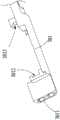
套管303的远端能够和钳口组件4相配合,具体而言,第一钳臂401和第二钳臂402之间设有弹性元件,使钳口组件保持在张开状态,当套管303向远端移动时,钳口组件4能从套管303的远端被收容于套管303内,此时弹性元件被压缩,钳口组件4闭合。当套管303向近端移动时,钳口组件4能从套管303的远端伸出,弹性元件释放能量而使钳口组件4打开。如图14所示,弹性元件可选用弹簧403。参考图20,在一个可选的实施例中,施夹钳具有转动关节7。具体的,主轴301包括第一轴部3014和第二轴部3015。第二轴部3015自操作组件5延伸。第一轴部3014设置于第二轴部3015的远端。第一轴部3014的近端与第二轴部3015的远端通过转动关节7连接,使得第一轴部3014能够相对第二轴部3015转动。钳口组件4与第一轴部3014的远端连接,使得钳口组件4能够在第一轴部3014的带动下相对第二轴部3015转动,以便于医生调整钳口组件4的位置和角度。在此实施例中,夹仓2设置于第一轴部3014,夹仓2与第一轴部3014通过卡扣结构连接,使得夹仓2能够随着钳口组件4一起转动。为了适应于第一轴部3014的转动, 本实施例中套管303分为第一管体3031和第二管体3032。第一管体3031套设于第一轴部3014和夹仓2。第二管体3032套设于第二轴部3015。第一管体3031与第二管体3032通过两个枢转件6连接。每一个枢转件6的近端与第二管体3032枢转连接,每一个枢转件6的远端与第一管体3031枢转连接。从而,当第一轴部3014转动时,第一轴部3014驱动第一管体3031转动,使得第一管体3031能够相对第二管体3032转动。下面描述本发明实施例中施夹钳的施夹过程。The distal end of the
在初始状态下(即送夹杆302未送夹时),送夹杆302的远端伸入至第二腔体204内或者未伸入至第二腔体204内,两种结构均不会影响施夹钳的正常使用。若送夹杆302的远端在初始状态下未伸入至第二腔体204内,当送夹杆302向施夹钳的远端移动时,送夹杆302的远端能从第二开口206处伸入第二腔体204内。In the initial state (that is, when the clamping
参考图15,本实施例中,送夹杆302的远端在初始状态下伸入至第二腔体204内,即送夹杆302的远端在初始状态下设置于第二腔体204内。如前所述,夹仓2包括三个夹子1,由上至下依次为夹子101、夹子102和夹子103。Referring to FIG. 15 , in this embodiment, the distal end of the clamping
参考图16,操纵操作组件5以驱动送夹杆302向施夹钳的远端(即向前)移动,使得送夹杆302的远端与第二腔体204中夹子103的第二端部110相抵接并推动夹子103沿第二方向运动,使得夹子103与限位件213脱离并从第一开口205处脱离第二腔体204后进入钳口组件4,此时送夹杆302仍然在夹子103的第二端部110抵推夹子103,以防止夹子103向近端移动而无法施夹。并且,此时由于送夹杆302的抵持作用,夹子101和夹子102不会在偏置组件的作用下向第二腔体204移动。Referring to FIG. 16 , the operating
夹子103进入钳口组件4中后,操纵操作组件5,操作组件5驱动套管303向施夹钳的远端移动,钳口组件4闭合,钳口组件4中的夹子103被夹持于被夹物(组织或血管)。After the
钳口组件4闭合后,操纵操作组件5,操作组件5驱动套管303向施夹钳的近端(即向后)移动,钳口组件4打开,夹子103与钳口组件4脱离。After the jaw assembly 4 is closed, the
夹子103与钳口组件4脱离后,操纵操作组件5,操作组件5驱动送夹杆302向施夹钳的近端移动,使得送夹杆302向近端移动至复位。当送夹杆302复位后,在偏置组件的作用下,第一腔体203中的夹子101的第二端部110沿限位斜面214移动,夹子102的第二端部110沿限位斜面214移动,夹子101和夹子102均具有向下和向前的位移,夹子102移动至第二腔体204内。按照上述对夹子101的施夹过程,对夹子102进行施夹。当夹子102与钳口组件4脱离后,在偏置组件的作用下,第一腔体203中的夹子101移动至第二腔体204内,再继续对夹子101进行施夹操作。After the
如前所述,本实施例中,对于夹仓本体中的三个夹子1,其第二端部110并不是对齐的,夹子101的第二端部110最靠近夹仓2的第二端202,夹子103的第二端部110最远离夹仓2的第二端202。若不设置限位斜面214,在初始状态,即未施夹时,夹子102的第二端部110会掉落至第二腔体204中并遮挡夹子103的第二端部110,由此,送夹杆302在向近端移动时,会抵推到夹子102的第二端部110,而无法抵推夹子103的第二端部110,从而施夹钳无法正常使用。同样的,在对夹子102进行施夹时,夹子101的第二端部110会掉落至第二腔体204内,送夹杆302无法抵推夹子102。本实施例在第一腔体203内设置有限位斜面214,限位斜面214能够对第一腔体203内的夹子1进行支撑,夹子101和夹子102能够大体上沿第二方向设置。夹子102的第二端部110不会掉落至第二腔体204内,从而不会影响夹子103的使用。同样的,在对夹子102进行施夹时,夹子101的第二端部110不会掉落至第二腔体204内,送夹杆302能够将夹子102抵推至钳口组件4中。As mentioned above, in this embodiment, for the three
综上,本实施方式中,通过将夹子1错位堆叠,能够节约空间,相邻夹子1的凸部能够相互避让,使夹子1能稳定的堆叠于夹仓2内。To sum up, in this embodiment, by stacking the
应当理解,虽然本说明书按照实施方式加以描述,但并非每个实施方式仅包含一个独立的技术方案,说明书的这种叙述方式仅仅是为清楚起见,本领域技术人员应当将说明书作为一个整体,各实施方式中的技术方案也可以经适当组合,形成本领域技术人员可以理解的其他实施方式。It should be understood that although this description is described according to implementation modes, not each implementation mode only contains an independent technical solution, and this description in the description is only for clarity, and those skilled in the art should take the description as a whole, and each The technical solutions in the embodiments can also be properly combined to form other embodiments that can be understood by those skilled in the art.
上文所列出的一系列的详细说明仅仅是针对本发明的可行性实施方式的具体说明,它们并非用以限制本发明的保护范围,凡未脱离本发明技艺精神所作的等效实施方式或变更均应包含在本发明的保护范围之内。The series of detailed descriptions listed above are only specific descriptions for feasible implementations of the present invention, and they are not intended to limit the protection scope of the present invention. Any equivalent implementation or implementation that does not depart from the technical spirit of the present invention All changes should be included within the protection scope of the present invention.
Claims (12)
Translated fromChinesePriority Applications (6)
| Application Number | Priority Date | Filing Date | Title |
|---|---|---|---|
| CN202111670812.3ACN116407201A (en) | 2021-12-31 | 2021-12-31 | Clamping chamber and clamp applicator |
| EP22915111.3AEP4458281A1 (en) | 2021-12-31 | 2022-12-29 | Clip cartridge and clip applier |
| US18/719,138US20250049441A1 (en) | 2021-12-31 | 2022-12-29 | Clip cartridge and clip applier |
| AU2022425321AAU2022425321B2 (en) | 2021-12-31 | 2022-12-29 | Clip cartridge and clip applier |
| MX2024008179AMX2024008179A (en) | 2021-12-31 | 2022-12-29 | Clip cartridge and clip applier. |
| PCT/CN2022/143619WO2023125862A1 (en) | 2021-12-31 | 2022-12-29 | Clip cartridge and clip applier |
Applications Claiming Priority (1)
| Application Number | Priority Date | Filing Date | Title |
|---|---|---|---|
| CN202111670812.3ACN116407201A (en) | 2021-12-31 | 2021-12-31 | Clamping chamber and clamp applicator |
Publications (1)
| Publication Number | Publication Date |
|---|---|
| CN116407201Atrue CN116407201A (en) | 2023-07-11 |
Family
ID=86998084
Family Applications (1)
| Application Number | Title | Priority Date | Filing Date |
|---|---|---|---|
| CN202111670812.3APendingCN116407201A (en) | 2021-12-31 | 2021-12-31 | Clamping chamber and clamp applicator |
Country Status (5)
| Country | Link |
|---|---|
| US (1) | US20250049441A1 (en) |
| EP (1) | EP4458281A1 (en) |
| CN (1) | CN116407201A (en) |
| MX (1) | MX2024008179A (en) |
| WO (1) | WO2023125862A1 (en) |
Families Citing this family (1)
| Publication number | Priority date | Publication date | Assignee | Title |
|---|---|---|---|---|
| CN116407201A (en)* | 2021-12-31 | 2023-07-11 | 江苏风和医疗器材股份有限公司 | Clamping chamber and clamp applicator |
Citations (8)
| Publication number | Priority date | Publication date | Assignee | Title |
|---|---|---|---|---|
| DE19903752C1 (en)* | 1999-01-30 | 2000-03-30 | Aesculap Ag & Co Kg | Clip magazine for haemostatic medical clip driver has independent actuated clamps for arms and bases of clips |
| US20130178880A1 (en)* | 2010-09-23 | 2013-07-11 | Aesculap Ag | Surgical clip device |
| CN105078536A (en)* | 2015-08-26 | 2015-11-25 | 施青青 | Duplex tissue clip and clip applier |
| CN106073853A (en)* | 2016-06-20 | 2016-11-09 | 江苏海泽医疗科技发展有限公司 | Semi-automatic medical continuously-applied Clip Applier with biology folder casket |
| US20190125352A1 (en)* | 2017-10-30 | 2019-05-02 | Ethicon Llc | Surgical clip applier comprising an empty clip cartridge lockout |
| CN111248972A (en)* | 2018-11-30 | 2020-06-09 | 苏州英途康医疗科技有限公司 | Medical instrument |
| US20230020577A1 (en)* | 2020-01-07 | 2023-01-19 | Intuitive Surgical Operations, Inc. | Surgical instruments for applying multiple clips |
| WO2023125862A1 (en)* | 2021-12-31 | 2023-07-06 | 江苏风和医疗器材股份有限公司 | Clip cartridge and clip applier |
Family Cites Families (4)
| Publication number | Priority date | Publication date | Assignee | Title |
|---|---|---|---|---|
| KR102647625B1 (en)* | 2018-07-18 | 2024-03-14 | 텔리플렉스 메디컬 인코포레이티드 | Clip Appliers and Cartridges |
| CN110037765B (en)* | 2019-05-24 | 2023-12-08 | 杭州圣石科技股份有限公司 | Continuous clip applier |
| US11395660B2 (en)* | 2019-08-05 | 2022-07-26 | Covidien Lp | Stackable ligation clip |
| CN113081145B (en)* | 2021-04-14 | 2022-06-24 | 常州市康蒂娜医疗科技有限公司 | Simple tissue clip repeating clip applying forceps |
- 2021
- 2021-12-31CNCN202111670812.3Apatent/CN116407201A/enactivePending
- 2022
- 2022-12-29MXMX2024008179Apatent/MX2024008179A/enunknown
- 2022-12-29WOPCT/CN2022/143619patent/WO2023125862A1/ennot_activeCeased
- 2022-12-29USUS18/719,138patent/US20250049441A1/enactivePending
- 2022-12-29EPEP22915111.3Apatent/EP4458281A1/enactivePending
Patent Citations (8)
| Publication number | Priority date | Publication date | Assignee | Title |
|---|---|---|---|---|
| DE19903752C1 (en)* | 1999-01-30 | 2000-03-30 | Aesculap Ag & Co Kg | Clip magazine for haemostatic medical clip driver has independent actuated clamps for arms and bases of clips |
| US20130178880A1 (en)* | 2010-09-23 | 2013-07-11 | Aesculap Ag | Surgical clip device |
| CN105078536A (en)* | 2015-08-26 | 2015-11-25 | 施青青 | Duplex tissue clip and clip applier |
| CN106073853A (en)* | 2016-06-20 | 2016-11-09 | 江苏海泽医疗科技发展有限公司 | Semi-automatic medical continuously-applied Clip Applier with biology folder casket |
| US20190125352A1 (en)* | 2017-10-30 | 2019-05-02 | Ethicon Llc | Surgical clip applier comprising an empty clip cartridge lockout |
| CN111248972A (en)* | 2018-11-30 | 2020-06-09 | 苏州英途康医疗科技有限公司 | Medical instrument |
| US20230020577A1 (en)* | 2020-01-07 | 2023-01-19 | Intuitive Surgical Operations, Inc. | Surgical instruments for applying multiple clips |
| WO2023125862A1 (en)* | 2021-12-31 | 2023-07-06 | 江苏风和医疗器材股份有限公司 | Clip cartridge and clip applier |
Also Published As
| Publication number | Publication date |
|---|---|
| EP4458281A1 (en) | 2024-11-06 |
| WO2023125862A1 (en) | 2023-07-06 |
| AU2022425321A1 (en) | 2024-07-11 |
| MX2024008179A (en) | 2024-07-19 |
| US20250049441A1 (en) | 2025-02-13 |
Similar Documents
| Publication | Publication Date | Title |
|---|---|---|
| US20230355237A1 (en) | Surgical stapler with toggling distal tip | |
| JP2021533930A (en) | Switching configuration for motorized range of motion surgical instruments | |
| BRPI0605646B1 (en) | PERFECTED ENDOSCOPIC SURGICAL CLAMP APPLICATOR | |
| BRPI0601402B1 (en) | SURGICAL CLIP APPLICATOR | |
| CN116407201A (en) | Clamping chamber and clamp applicator | |
| CN114680993A (en) | clamp applier | |
| WO2023125863A1 (en) | Clip applicator | |
| US20070219581A1 (en) | Bending Action Member, Multi-Slider Linkage Mechanism, Actuator And Manipulator | |
| CN102090912B (en) | Surgical clip applier | |
| CN104490438A (en) | Staple bin assembly and medical stapler using staple bin assembly | |
| CN204379347U (en) | Nail bin groupware and use the Medical stapler of this nail bin groupware | |
| CN213665528U (en) | Jaw assembly and clip applier | |
| WO2023083272A1 (en) | Clip applier | |
| CN216221543U (en) | Anastomat assembly and anastomat | |
| CN108420493B (en) | Flexible clip applier for surgical robot | |
| CN216495453U (en) | Cutting anastomat guide structure | |
| CN204379344U (en) | Nail bin groupware and apply the Medical stapler of this nail bin groupware | |
| CN114305573B (en) | Jaw Assemblies and Clip Appliers | |
| CN213606602U (en) | Nail box and clamp of detachable nail bin assembly | |
| US11147557B1 (en) | Surgical clip applicator | |
| CN213098090U (en) | Interlock device of pocket suture operation under chamber mirror | |
| CN116407206A (en) | Clip Applier | |
| CN204562262U (en) | Medical stapler | |
| CN217987646U (en) | Clip applier | |
| CN108354647A (en) | A kind of hemostatic clamp Clip Applier driving mechanism |
Legal Events
| Date | Code | Title | Description |
|---|---|---|---|
| PB01 | Publication | ||
| PB01 | Publication | ||
| SE01 | Entry into force of request for substantive examination | ||
| SE01 | Entry into force of request for substantive examination |