CN116407161A - biopsy device - Google Patents
biopsy deviceDownload PDFInfo
- Publication number
- CN116407161A CN116407161ACN202111643018.XACN202111643018ACN116407161ACN 116407161 ACN116407161 ACN 116407161ACN 202111643018 ACN202111643018 ACN 202111643018ACN 116407161 ACN116407161 ACN 116407161A
- Authority
- CN
- China
- Prior art keywords
- needle
- needle tube
- distal end
- biopsy device
- adjusting structure
- Prior art date
- Legal status (The legal status is an assumption and is not a legal conclusion. Google has not performed a legal analysis and makes no representation as to the accuracy of the status listed.)
- Pending
Links
Images


Classifications
- A—HUMAN NECESSITIES
- A61—MEDICAL OR VETERINARY SCIENCE; HYGIENE
- A61B—DIAGNOSIS; SURGERY; IDENTIFICATION
- A61B10/00—Instruments for taking body samples for diagnostic purposes; Other methods or instruments for diagnosis, e.g. for vaccination diagnosis, sex determination or ovulation-period determination; Throat striking implements
- A61B10/02—Instruments for taking cell samples or for biopsy
- A61B10/0233—Pointed or sharp biopsy instruments
- A61B10/0283—Pointed or sharp biopsy instruments with vacuum aspiration, e.g. caused by retractable plunger or by connected syringe
- A—HUMAN NECESSITIES
- A61—MEDICAL OR VETERINARY SCIENCE; HYGIENE
- A61B—DIAGNOSIS; SURGERY; IDENTIFICATION
- A61B10/00—Instruments for taking body samples for diagnostic purposes; Other methods or instruments for diagnosis, e.g. for vaccination diagnosis, sex determination or ovulation-period determination; Throat striking implements
- A61B10/02—Instruments for taking cell samples or for biopsy
- A61B10/0233—Pointed or sharp biopsy instruments
- A61B10/0266—Pointed or sharp biopsy instruments means for severing sample
- A—HUMAN NECESSITIES
- A61—MEDICAL OR VETERINARY SCIENCE; HYGIENE
- A61B—DIAGNOSIS; SURGERY; IDENTIFICATION
- A61B10/00—Instruments for taking body samples for diagnostic purposes; Other methods or instruments for diagnosis, e.g. for vaccination diagnosis, sex determination or ovulation-period determination; Throat striking implements
- A61B10/02—Instruments for taking cell samples or for biopsy
- A61B10/04—Endoscopic instruments, e.g. catheter-type instruments
- A—HUMAN NECESSITIES
- A61—MEDICAL OR VETERINARY SCIENCE; HYGIENE
- A61B—DIAGNOSIS; SURGERY; IDENTIFICATION
- A61B17/00—Surgical instruments, devices or methods
- A61B17/34—Trocars; Puncturing needles
- A—HUMAN NECESSITIES
- A61—MEDICAL OR VETERINARY SCIENCE; HYGIENE
- A61B—DIAGNOSIS; SURGERY; IDENTIFICATION
- A61B17/00—Surgical instruments, devices or methods
- A61B17/34—Trocars; Puncturing needles
- A61B17/3417—Details of tips or shafts, e.g. grooves, expandable, bendable; Multiple coaxial sliding cannulas, e.g. for dilating
- A61B17/3421—Cannulas
- A—HUMAN NECESSITIES
- A61—MEDICAL OR VETERINARY SCIENCE; HYGIENE
- A61B—DIAGNOSIS; SURGERY; IDENTIFICATION
- A61B17/00—Surgical instruments, devices or methods
- A61B17/34—Trocars; Puncturing needles
- A61B17/3478—Endoscopic needles, e.g. for infusion
Landscapes
- Health & Medical Sciences (AREA)
- Life Sciences & Earth Sciences (AREA)
- Surgery (AREA)
- Biomedical Technology (AREA)
- General Health & Medical Sciences (AREA)
- Heart & Thoracic Surgery (AREA)
- Medical Informatics (AREA)
- Molecular Biology (AREA)
- Pathology (AREA)
- Animal Behavior & Ethology (AREA)
- Engineering & Computer Science (AREA)
- Public Health (AREA)
- Veterinary Medicine (AREA)
- Nuclear Medicine, Radiotherapy & Molecular Imaging (AREA)
- Radiology & Medical Imaging (AREA)
- Infusion, Injection, And Reservoir Apparatuses (AREA)
- Surgical Instruments (AREA)
Abstract
Translated fromChinese
Description
Translated fromChinese技术领域technical field
本发明属于医疗器械领域,尤其涉及一种活检装置。The invention belongs to the field of medical instruments, in particular to a biopsy device.
背景技术Background technique
活检装置是目前常用的穿刺活检用设备。传统的活检装置的针套其远端从壳体的远端伸出壳体外,且伸出的长度是固定不变的。当应对身体构造上的具有差异的不同病人或者目标组织位于身体的不同位置处时,针套所伸出的长度可能过短或过长,导致需要更换能伸出适配的针套,灵活性较差。A biopsy device is currently the most commonly used device for needle biopsy. The distal end of the needle sheath of the traditional biopsy device protrudes out of the housing from the distal end of the housing, and the protruding length is constant. When dealing with different patients with differences in body structure or target tissues located at different positions in the body, the protruding length of the needle sheath may be too short or too long, resulting in the need to replace the needle sheath that can be extended and adapted, and the flexibility is relatively small Difference.
发明内容Contents of the invention
基于此,有必要提供一种活检装置,旨在解决现有技术的活检装置灵活性较差的技术问题。Based on this, it is necessary to provide a biopsy device aimed at solving the technical problem of poor flexibility of the biopsy device in the prior art.
活检装置包括壳体、抽吸组件及针套调节结构,所述抽吸组件包括针套,所述针套穿设于所述壳体的远端,且所述针套的远端突出所述壳体的远端;The biopsy device includes a housing, a suction assembly and a needle sleeve adjustment structure, the suction assembly includes a needle sleeve, the needle sleeve is passed through the distal end of the housing, and the distal end of the needle sleeve protrudes from the the distal end of the housing;
所述针套穿设于所述针套调节结构,且可相对所述针套调节结构移动,所述针套调节结构设于所述壳体,且至少部分针套调节结构可沿所述针套移动,以调节所述针套的远端到所述针套调节结构远端之间的距离。The needle cover is passed through the needle cover adjustment structure and can move relative to the needle cover adjustment structure. The needle cover adjustment structure is arranged on the housing, and at least part of the needle cover adjustment structure can move along the needle cover. The cover moves to adjust the distance between the distal end of the needle cover and the distal end of the needle cover adjusting structure.
本发明提供的活检装置包括针套调节结构、壳体和抽吸组件,抽吸组件包括针套,针套调节结构能根据不同病人身体构造调节针套调节结构的远端与针套的远端之间的距离,以使针套的远端能抵达目标组织处,能兼顾不同病人身体构造上的差异,具有较高的灵活性。The biopsy device provided by the present invention includes a needle cover adjustment structure, a housing and a suction assembly, the suction assembly includes a needle cover, and the needle cover adjustment structure can adjust the distal end of the needle cover adjustment structure and the distal end of the needle cover according to different patient body structures The distance between them allows the distal end of the needle sheath to reach the target tissue, which can take into account the differences in the body structure of different patients, and has high flexibility.
附图说明Description of drawings
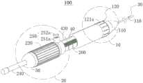
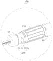
图1是本发明一个实施例提供的活检装置立体图;Fig. 1 is a perspective view of a biopsy device provided by an embodiment of the present invention;
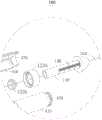
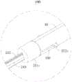
图2是图1的活检装置的爆炸图;Figure 2 is an exploded view of the biopsy device of Figure 1;
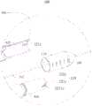
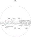
图3是图1的活检装置的竖剖图;Fig. 3 is a vertical sectional view of the biopsy device of Fig. 1;
图4是图1中针套调节结构的其他实施例的立体图;Fig. 4 is a perspective view of other embodiments of the needle cover adjustment structure in Fig. 1;
图5是图4中针套调节结构的爆炸图;Fig. 5 is an exploded view of the needle cover adjustment structure in Fig. 4;
图6是图4的针套调节结构的竖剖图;Fig. 6 is a vertical sectional view of the needle cover adjustment structure of Fig. 4;
图7是图1中针套调节结构的其他实施例的立体图;Fig. 7 is a perspective view of other embodiments of the needle cover adjustment structure in Fig. 1;
图8是图7中针套调节结构的爆炸图;Fig. 8 is an exploded view of the needle cover adjustment structure in Fig. 7;
图9是图1中针套调节结构的其他实施例的立体图;Fig. 9 is a perspective view of other embodiments of the needle cover adjustment structure in Fig. 1;
图10是图9中针套调节结构的爆炸图;Fig. 10 is an exploded view of the needle cover adjustment structure in Fig. 9;
图11是图9的针套调节结构的竖剖图。Fig. 11 is a vertical sectional view of the needle cover adjustment structure in Fig. 9 .
图12是图1中针管调节结构的其他实施例的立体图;Fig. 12 is a perspective view of other embodiments of the needle tube adjustment structure in Fig. 1;
图13是图12中第一限位组件的立体图;Fig. 13 is a perspective view of the first limiting assembly in Fig. 12;
图14是图12的针管调节结构的竖剖图;Fig. 14 is a vertical sectional view of the needle tube adjustment structure of Fig. 12;
图15是图1中针管调节结构的其他实施例的立体图;Fig. 15 is a perspective view of other embodiments of the needle tube adjustment structure in Fig. 1;
图16是图15中针管调节结构的爆炸图;Figure 16 is an exploded view of the needle tube adjustment structure in Figure 15;
图17是图15的针管调节结构的竖剖图;Fig. 17 is a vertical sectional view of the needle tube adjustment structure of Fig. 15;
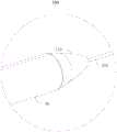
图18是图3的A处其他实施例的局部放大图。Fig. 18 is a partially enlarged view of other embodiments at A in Fig. 3 .
附图标记:Reference signs:
100、活检装置;100. Biopsy device;
10、针套调节结构;110、移动件;10. Needle sleeve adjustment structure; 110. Moving parts;
120、第一限位组件;121a、第一转动件;122a、压紧件;123a、导向件;1231a、导向孔;121b、轴向挤压件;1211b、环形凹槽;1212b、外环壁;1213b、内环壁;122b、压紧件;123b、螺纹结构;121c、卡扣件;1211c、凸起;122c、扣合部;121d、第二转动件;122d、螺纹结构;120, the first limit assembly; 121a, the first rotating member; 122a, the pressing member; 123a, the guide member; 1231a, the guide hole; 121b, the axial extrusion member; 1211b, the annular groove; 1212b, the outer ring wall ; 1213b, inner ring wall; 122b, pressing piece; 123b, thread structure; 121c, buckle piece; 1211c, protrusion; 122c, fastening part;
130、第二刻度尺;130, the second scale;
20、针管调节结构;20. Needle adjustment structure;
210、针管推动件;220、针管驱动件;230、螺纹结构;240、连接件;241、螺纹鲁尔结构;242、卡接部;210. Needle pusher; 220. Needle drive; 230. Thread structure; 240. Connector; 241. Thread Luer structure; 242. Clamping part;
250、第二限位组件;251a、限位件;252a、锁紧件;251b、限位件;252b、持拿件;251c、第三转动件;2511c、第一卡沿;252c、卡位件;250, the second limiting component; 251a, the limiting member; 252a, the locking member; 251b, the limiting member; 252b, the holding member; 251c, the third rotating member; 2511c, the first card edge; pieces;
260、第二刻度尺;260, the second scale;
30、抽吸组件;310、针套;315、固定块;320、针管;330、针芯;40、壳体;410、半壳;420、挡板;430、配合槽;440、缺口;450、限位槽;460、第二卡沿;470、配合件;480、台阶;30. Suction assembly; 310. Needle cover; 315. Fixed block; 320. Needle tube; 330. Needle core; 40. Shell; 410. Half shell; 420. Baffle plate; , limit slot; 460, the second card edge; 470, fittings; 480, steps;
50、近端锁紧件;60、远端锁紧件;70、定位块;80、感应件。50, the proximal locking element; 60, the distal locking element; 70, the positioning block; 80, the sensing element.
具体实施方式Detailed ways
为使本发明的上述目的、特征和优点能够更加明显易懂,下面结合附图对本发明的具体实施方式做详细的说明。在下面的描述中阐述了很多具体细节以便于充分理解本发明。但是本发明能够以很多不同于在此描述的其它方式来实施,本领域技术人员可以在不违背本发明内涵的情况下做类似改进,因此本发明不受下面公开的具体实施的限制。In order to make the above objects, features and advantages of the present invention more comprehensible, specific implementations of the present invention will be described in detail below in conjunction with the accompanying drawings. In the following description, numerous specific details are set forth in order to provide a thorough understanding of the present invention. However, the present invention can be implemented in many other ways different from those described here, and those skilled in the art can make similar improvements without departing from the connotation of the present invention, so the present invention is not limited by the specific implementations disclosed below.
除非另有定义,本文所使用的所有的技术和科学术语与属于本发明的技术领域的技术人员通常理解的含义相同。本文中在本发明的说明书中所使用的术语只是为了描述具体的实施例的目的,不是旨在于限制本发明。Unless otherwise defined, all technical and scientific terms used herein have the same meaning as commonly understood by one of ordinary skill in the technical field of the invention. The terms used herein in the description of the present invention are for the purpose of describing specific embodiments only, and are not intended to limit the present invention.
在介入医疗器械领域,定义“远端”为手术过程中远离操作者的一端,定义“近端”为手术过程中靠近操作者的一端。“轴向”指平行于医疗器械远端中心和近端中心连线的方向,“径向”指垂直于上述轴向的方向。In the field of interventional medical devices, the "distal end" is defined as the end away from the operator during the operation, and the "proximal end" is defined as the end close to the operator during the operation. "Axial" refers to the direction parallel to the line connecting the center of the distal end and the center of the proximal end of the medical device, and "radial" refers to the direction perpendicular to the aforementioned axial direction.
如图1至图3所示,为本发明第一实施例提供的活检装置1。该活检装置1用于在人体内进行刺穿,以抽取人体的活体组织。具体不限于肝、肾、淋巴结等的穿刺抽取组织。在本实施例,以活检装置1穿刺纵膈淋巴结为例进行说明。As shown in FIG. 1 to FIG. 3 , it is a
如图1和图2所示,活检装置1包括针套调节结构10、抽吸组件30及壳体40。抽吸组件30包括针套310。针套310可呈中空管状,且可沿轴向穿设于壳体40。具体在本实施例中,针套310与壳体40固定连接。针管320可呈中空管状,且可活动地沿轴向穿设于针套310。针套310可活动地穿设于针套调节结构10。至少部分针套调节结构10可设于壳体40内。针套调节结构10可沿壳体40的轴向移动。由于针套310与壳体40固定连接,针套310穿设于壳体40和针套调节结构10内,且远端能从针套调节结构10的远端伸出。则可通过调节针套调节结构10伸出壳体40的长度,以调节针套310的远端到针套调节结构10远端的距离,以能兼顾不同病人身体构造上的差异。As shown in FIGS. 1 and 2 , the
该活检装置1的工作原理大致如下:The working principle of the
通过超声识别纵膈淋巴结的病变区域。将针套310插入内镜的工作通道内。缓慢推进活检装置100,以使针套310的远端与内镜的工作通道连接。通过调节针套调节结构10使针套310的远端到针套调节结构10远端之间的距离至目标长度。此时,可通过内镜稍微看到针套310的远端。Diseased areas of the mediastinal lymph nodes were identified by ultrasound. The
综上,相比现有技术,该活检装置1至少具有以下有益效果:In summary, compared with the prior art, the
该活检装置1的针套调节结构10能根据不同病人身体构造调节针套调节结构10的远端与针套310的远端之间的距离,以使针套310的远端能抵达目标组织处,能兼顾不同病人身体构造上的差异,具有较高的灵活性。The needle
在本实施例中,如图2所示,壳体40包括两个对称设置的半壳410。壳体40的远端设有远端锁紧件60,近端设有近端锁紧件50。远端锁紧件60和近端锁紧件50均可呈环状结构。远端锁紧件60可套设于壳体40的远端,并与壳体40的远端螺接,以将两个半壳410的远端固定连接。近端锁紧件50可套设于壳体40的近端,并与壳体40的近端螺接,以将两个半壳410的近端固定连接。将壳体40设置成上述可拆装的结构是为了方便将其他零部件装配在壳体40内。当然,壳体40也可以是一体成型的结构。In this embodiment, as shown in FIG. 2 , the
在本实施例中,如图1至图3所示,针套调节结构10包括移动件110。具体在本实施例中,移动件110可以呈中空的管状结构。部分针套310位于壳体40内,另一部分针套310则从壳体40的远端穿设于移动件110,并从移动件110的远端伸出。移动件110能相对壳体40轴向移动,以调节针套310的远端能伸出移动件110的远端的长度,即调节针套310的远端到移动件110的远端之间的距离。In this embodiment, as shown in FIGS. 1 to 3 , the needle
在本实施例中,如图2和图3所示,针套调节结构10还包括第一限位组件120,用以限制移动件110沿轴向移动的行程。第一限位组件120能够防止移动件110因沿轴向随意移动使针套310的远端到移动件110的远端之间的距离发生变化,而产生误操作的情况出现。In this embodiment, as shown in FIG. 2 and FIG. 3 , the needle
在本实施例中,如图2所示,移动件110上可设有第一刻度尺130,且可沿轴向设置。第一刻度尺130可用以显示针套310的远端到移动件110的远端之间的距离,以能根据不同病人身体构造上的差异控制针管320的远端到移动件110的远端之间的距离。In this embodiment, as shown in FIG. 2 , a
在本实施例中,第一刻度尺130的数值沿轴向由近端至远端逐渐减小。也就是说,移动件110沿轴向由近端至远端移动,针套310的远端与移动件110的远端之间的距离逐渐减小。进一步地,第一刻度尺130的量程范围可以是0-50mm。In this embodiment, the value of the
在本实施例中,如图1至图3所示,第一限位组件120包括第一转动件121a和压紧件122a及固设于壳体40内部的导向件123a。具体在本实施例中,移动件110穿可移动地穿设于壳体40的远端。第一转动件121a可呈环状结构;压紧件122a包括块状结构;导向件123a呈环状结构,且具有贯穿其内外表面的导向孔1231a。第一转动件121a的内侧可设有凸台。第一转动件121a可转动套设于壳体40。压紧件122a可沿径向穿过壳体40,并设于移动件110和第一转动件121a之间,且活动地收容于导向孔1231a中。也就是说,移动件110穿设于导向件123a,导向件123a穿设于第一转动件121a内,压紧件122a位于第一转动件121a及导向件123a之间。可以理解地,其他实施例中,导向件123a也可以与外壳40一体成型。In this embodiment, as shown in FIGS. 1 to 3 , the first limiting
第一转动件121a转动使凸台压抵于压紧件122a,以使压紧件122a能径向压抵于移动件110,能够限制移动件110沿轴向移动。第一转动件121a转动使凸台脱离压紧件122a,以使压紧件122a能从移动件110上松开,移动件110能够继续沿轴向移动。The rotation of the first
在本实施例中,如图2所示,移动件110上的第一刻度尺130与壳体40的远端重叠的位置所显示的数值,该数值即为移动件110轴向移动的距离。In this embodiment, as shown in FIG. 2 , the value displayed at the position where the
在本实施例中,如图1至图3所示,活检装置100还包括针管调节结构20,抽吸组件30还包括针管310。针管调节结构20可设于壳体40,且与针管320相连。针管调节结构20可转动以带动针管320的远端能伸出针套310的远端外,以使针管320能平稳顺滑地刺入纵膈淋巴结内,降低了对操作者的要求,也降低因针管320弯曲断裂导致的医疗事故的弊端,同时兼容了进针的精度、操作的安全性及工作效率。In this embodiment, as shown in FIGS. 1 to 3 , the
在本实施例中,如图2所示,针管调节结构20包括针管推动件210和针管驱动件220。具体在本实施例中,针管推动件210呈块状结构,针管驱动件220呈中空圆筒状结构,针管推动件210可位于针管驱动件220内。针管推动件210可与针管驱动件220转动连接。具体地,针管驱动件220转动,以驱动针管推动件210沿轴向移动。或者,针管推动件210相对针管驱动件220转动的同时,针管推动件210能沿轴向移动。针管320可与针管推动件210连接。具体在本实施例中,针管320的近端与针管推动件210固定连接。针管驱动件220与针管推动件210相对转动,以使针管推动件210能沿轴向移动。针管推动件210沿轴向移动能带动针管320沿轴向移动。针管推动件210沿轴向朝远端移动能使针管320的远端伸出针套310的远端外,以使针管320能平稳顺滑地刺入纵膈淋巴结。In this embodiment, as shown in FIG. 2 , the needle
在本实施例中,如图3所示,针管推动件210和针管驱动件220之间可设有螺纹结构230。针管推动件210和针管驱动件220可通过螺纹结构230转动连接。螺纹结构230包括内螺纹和与该内螺纹适配的外螺纹。内螺纹可设于针管驱动件220的内壁上,外螺纹可设于针管推动件210的周壁上。或者,内螺纹可设于针管推动件210的周壁上,外螺纹可设于针管驱动件220的内壁上。In this embodiment, as shown in FIG. 3 , a threaded
在本实施例中,如图3所示,针管驱动件220可套设于壳体40,此时,外螺纹可沿径向穿过壳体40,并与内螺纹螺接配合。或者,针管驱动件220与针管推动件210均可设于壳体40内,此时,外螺纹与内螺纹直接螺接配合。In this embodiment, as shown in FIG. 3 , the needle
在本实施例中,如图2所示,针管推动件210的近端可固定设有连接件240,连接件240可沿轴向设置。部分连接件240位于针管驱动件220内。连接件240可在针管推动件210的带动下沿轴向移动。连接件240的远端与针管推动件210可螺接固定,也可以为一体成型结构。In this embodiment, as shown in FIG. 2 , a connecting
在本实施例中,如图1和图2所示,抽吸组件30还包括针芯330。针芯330可沿轴向穿设于连接件240、针管推动件210和针管320,并填堵针管320的内腔。以防止抽吸组件30在刺入人体的过程中,且还未抵达纵膈淋巴结的病变区域前,其他非目标组织进入针管320内。待针管320刺入纵膈淋巴结的病变区域后,可将针芯330从针管320内抽出。In this embodiment, as shown in FIGS. 1 and 2 , the
在本实施例中,如图2所示,连接件240的近端可具有螺纹鲁尔结构241,用于供注射器旋接在连接件240上,以能通过注射器抽取纵膈淋巴结的病变区域的组织。In this embodiment, as shown in FIG. 2 , the proximal end of the connecting
在本实施例中,如图2和图3所示,针管调节结构20还包括第二限位组件250,用以限制针管驱动件220沿轴向移动的行程。第二限位组件250能够防止针管320因沿轴向随意移动而产生误操作的情况出现。In this embodiment, as shown in FIG. 2 and FIG. 3 , the needle
在本实施例中,针管驱动件220能在行程内前后反复移动,以使针管320的远端能够反复伸出针套310以反复刺戳纵膈淋巴结。反复刺戳纵膈淋巴结能将纵膈淋巴结组织戳松,以方便抽取纵膈淋巴结组织。In this embodiment, the
在本实施例中,如图1至图3所示,第二限位组件250包括限位件251a。具体在本实施例中,该限位件251a可以呈环状结构。针管驱动件220和限位件251a可套设于壳体40,且限位件251a可位于针管驱动件220的远端。当针管驱动件220在轴向上自近端向远端移动至针管驱动件220与限位件251a抵接时,限位件251a限制了针管驱动件220继续向远端移动。由于针管驱动件220沿轴向移动会带动针管推动件210及固定在针管推动件210上的针管320沿轴向移动,因此限位件251a能有效防止针管320穿刺纵膈淋巴结的深度过深。限位件251a能在壳体40上沿轴向移动,以调节针管驱动件220沿轴向移动的行程,以实现调节针管320的远端伸出针套310的远端的长度。并且,当通过限位件251a确定好针管驱动件220可移动的行程后,针管驱动件220能在该行程内反复移动。In this embodiment, as shown in FIGS. 1 to 3 , the second limiting
在本实施例中,如图2和图3所示,第二限位组件250还包括锁紧件252a。具体在本实施例中,锁紧件252a可以是螺钉或螺栓等。锁紧件252a能穿设于限位件251a,并沿径向锁紧于壳体40上,以限制限位件251a沿轴向移动。壳体40上可设有供锁紧件252a插入的配合槽430,该配合槽430可沿轴向设置。配合槽430能有效防止锁紧件252a锁紧壳体40时,在壳体40的表面上出现打滑的现象。In this embodiment, as shown in FIG. 2 and FIG. 3 , the second limiting
或者,锁紧件252a能穿设并锁紧限位件251a。当锁紧件252a松开时,限位件251a也松开壳体40,此时限位件251a能在壳体40上沿轴向移动。当锁紧件252a锁紧时,限位件251a收缩以锁紧壳体40,此时限位件251a固定在壳体40上。Alternatively, the locking
在本实施例中,如图1和图2所示,壳体40上可设有第二刻度尺260,且可沿轴向设置。第二刻度尺260可用以显示针管320的远端从针套310的远端伸出的长度,以能根据纵膈淋巴结上具体病变的区域调节针管320能刺入纵膈淋巴结内的深度。可以理解地,壳体40上的第二刻度尺260与限位件251a的近端重叠的位置所显示的数值,即为针管320的远端能从针套310的远端伸出的最大长度。基于此,当针管驱动件220沿轴向移动至针管驱动件220的远端与限位件251b抵接时,针管320的远端从针套310的远端伸出的长度为针管320的远端能从针套310的远端伸出的最大长度。In this embodiment, as shown in FIGS. 1 and 2 , a
在本实施例中,第二刻度尺260的数值沿轴向由近端至远端逐渐增大。也就是说,针管驱动件220沿轴向由近端至远端移动,针管320的远端从针套310的远端伸出的长度逐渐增大。进一步地,第二刻度尺260的量程范围可以是0-40mm。在其他实施例中,第二刻度尺260的量程范围也可以是0-60mm或0-80mm。可根据人体所要刺穿的部位及纵膈淋巴结病变区域的深度选择适配的量程。In this embodiment, the value of the
在其他实施例中,本实施例提供的活检装置100与第一实施例基本相同。如图4至图6所示,本实施例与第一实施例不同的是,在本实施例中,第一限位组件120包括轴向挤压件121b(也称第一转动件)和压紧件122b。具体在本实施例中,移动件110穿可移动地穿设于壳体40的远端。压紧件122b呈环状结构,具体可以是橡胶圈。轴向挤压件121b呈环状结构,且轴向挤压件121b的近端设置有开口朝向近端的环形凹槽1211b。轴向挤压件121b沿径向位于环形凹槽1211b外侧的一侧为外环壁1212b,轴向挤压件121b上沿径向位于环形凹槽1211b内侧的一侧为内环壁1213b,且内环壁1213b的轴向长度小于外环壁1212b的轴向长度。壳体40远端的端面上可设置有配合件470,该配合件470可以呈环状结构。配合件470可插设于轴向挤压件121b的环形凹槽1211b内,且轴向挤压件121b可相对配合件470转动。压紧件122b可套设于移动件110上,且沿轴向位于壳体40的远端端面与轴向挤压件121b的内环壁1213b之间,沿径向位于移动件110与配合件470之间。In other embodiments, the
轴向挤压件121b相对配合件470转动以沿轴向移动靠近壳体40设有配合件470的远端端面,从而缩小轴向挤压件121b的槽底与配合件470在轴向上的间隙,以挤压压紧件122b。压紧件122b受到挤压后沿径向形变,以能挤压移动件110,从而能够限制移动件110沿轴向移动。The
轴向挤压件121b以上述相反方向相对配合件470转动,则可增大轴向挤压件121b的槽底与配合件470在轴向上的间隙,以解除对压紧件122b的挤压力。压紧件122b受力解除后形变恢复,以解除对移动件110的挤压,移动件110能够继续沿轴向移动。When the
在本实施例中,如图6所示,轴向挤压件121b的外环壁1212b和配合件470之间可设有螺纹结构123b。轴向挤压件121b的外环壁1212b和配合件470可通过螺纹结构123b转动连接,以使轴向挤压件121b在转动的同时能沿轴向移动。螺纹结构123b包括内螺纹和与该内螺纹适配的外螺纹。内螺纹可设于轴向挤压件121b的外环壁1212b的内侧,外螺纹可设于配合件470的外壁上。或者,内螺纹可设于配合件470的外壁上,外螺纹可设于轴向挤压件121b的外环壁1212b的内侧。可以理解地,若壳体40采用两个半壳410拼装而成,则本实施例中的轴向挤压件121b同时具体锁紧两个半壳410的远端的作用。即可替代远端锁紧件60。In this embodiment, as shown in FIG. 6 , a
在本实施例中,如图5所示,移动件110上的第一刻度尺130与轴向挤压件121b的远端重叠的位置所显示的数值,该数值即为移动件110轴向移动的距离。In this embodiment, as shown in FIG. 5 , the value displayed at the position where the
在其他实施例中,本实施例提供的活检装置100与第一实施例基本相同。如图7和图8所示,本实施例与第一实施例不同的是,在本实施例中,第一限位组件120包括卡扣件121c和多个扣合部122c。具体在本实施例中,移动件110穿可移动地套设于壳体40的远端。卡扣件121c沿轴向设于壳体40的远端,且沿径向靠近移动件110的一侧具有凸起1211c。壳体40的远端可设有缺口440,卡扣件121c可位于缺口440内。多个扣合部122c可沿轴向间隔布设于移动件110上。扣合部122c可以为与卡扣件121c的凸起1211c适配的孔状结构。进一步地,第一限位组件120可设置有两个,即卡扣件121c可设置有两个,扣合部122c设置有两列。两个卡扣件121c可沿径向相对设置,两列扣合部122c可对应两个卡扣件121c设置,各卡扣件121c可与对应一列的各扣合部122c配合,以增加移动件110与壳体40相对固定时的稳定性。In other embodiments, the
卡扣件121c与扣合部122c扣合能限制移动件110沿轴向移动。卡扣件121c从扣合部122c脱出,移动件110能机械沿轴向移动。通过使卡扣件121c的凸起1211c与轴向上各位置处的扣合部122c配合,调节移动件110的远端与壳体40的远端之间的距离,以实现调节针套310的远端与移动件110的远端之间的距离。The locking
在本实施例中,如图8所示,第一刻度尺130包括设置在各扣合部122c上的数值。卡扣件121c所扣入的扣合部122c上对应的数值,数值即为移动件110轴向移动的不同距离(即不同档位)。In this embodiment, as shown in FIG. 8 , the
在其他实施例中,本实施例提供的活检装置100与第一实施例基本相同。如图9至图11所示,本实施例与第一实施例不同的是,在本实施例中,第一限位组件120包括第二转动件121d。具体在本实施例中,移动件110可移动地穿设于壳体40的远端。针套310通过固定块315固定于外壳40。第二转动件121d可设于移动件110的近端,且与壳体40转动连接。第二转动件121d与壳体40相对静止时,能限制移动件110沿轴向移动。第二转动件121d相对壳体40转动的同时能沿轴向移动,并带动移动件110转动且沿轴向移动,以调节移动件110的远端与壳体40的远端之间的距离,实现调节针套310的远端与移动件110的远端之间的距离。In other embodiments, the
在本实施例中,如图11所示,第二转动件121d和壳体40之间可设有螺纹结构122d。第二转动件121d和壳体40可通过螺纹结构122d转动连接,以使第二转动件121d在转动的同时能沿轴向移动。螺纹结构122d包括内螺纹和与该内螺纹适配的外螺纹。内螺纹可设于壳体40的内侧,外螺纹可设于第二转动件121d的周壁上。或者,内螺纹可设于第二转动件121d的周壁上,外螺纹可设于壳体40的内侧。In this embodiment, as shown in FIG. 11 , a
在其他实施例中,本实施例提供的活检装置100与第一实施例基本相同。如图12至图14所示,本实施例与第一实施例不同的是,在本实施例中,第二限位组件250包括限位件251b。具体在本实施例中,限位件251b可以是卡环。针管驱动件220套设于壳体40。限位件251b可卡设于壳体40上,且两端分别与近端锁紧件50的远端与针管驱动件220的近端抵接,以限制针管驱动件220沿轴向移动。当限位件251b从壳体40上取下后,壳体40上空出一段供针管驱动件220沿轴向移动的空间,此时针管驱动件220能在壳体40上反复移动。In other embodiments, the
在本实施例中,如图13所示,第二限位组件250还包括设于限位件251b上的持拿件252b,以方便将限位件251b从壳体40上拔取出来。In this embodiment, as shown in FIG. 13 , the second limiting
在其他实施例中,本实施例提供的活检装置100与第一实施例基本相同。如图15至图17所示,本实施例与第一实施例不同的是,在本实施例中,第二限位组件250包括第三转动件251c和卡位件252c。针管320的近端固接在中空的连接件240中。针芯330穿设于连接件240中,且针芯330的近端从连接件240的近端穿出。连接件240穿设于第三转动件251c中,且可相对第三转动件251c轴向移动。针管驱动件220设于壳体40内。第三转动件251c可转动连接于壳体40的近端。第三转动件251c相对壳体40转动以带动连接件240转动,进而带动与连接件240远端相螺接的针管推动件210一起转动,以使针管推动件210与针管驱动件220转动连接,则在针管驱动件220的配合下针管推动件210与连接件240一起带动针管320转动的同时沿轴向相对针套310移动。In other embodiments, the
外壳40沿轴向设置有限位槽450。卡位件252c可设于针管驱动件220上,且能穿过限位槽450并伸出壳体40外。拨动卡位件252c使卡位件252c在限位槽450内沿轴向反复移动,以带动针管驱动件220沿轴向反复移动,从而可以带动针管320实现反复进针。The
可以理解地,其他实施例中,针管320的近端可以固接于针管推动件210,不限于本实施例,只要转动的第三转动件251c能带动针管320旋转进针即可。Understandably, in other embodiments, the proximal end of the
可以理解地,如图17所示,若壳体40采用两个半壳410拼装而成,则本实施例中的第三转动件251c同时具体锁紧两个半壳410的近端的作用。即可替代近端锁紧件50。It can be understood that, as shown in FIG. 17 , if the
在本实施例中,如图16所示,自连接件240的外壁沿径向延伸形成卡接部242,该卡接部242与第三转动件251c卡接配合,以在第三转动件251c转动时能带动连接件240转动,且相对第三转动件521c轴向移动。卡接部242可设置至少两个,各卡接部242可沿连接件240的周向间隔布设。In this embodiment, as shown in FIG. 16 , an engaging
在本实施例中,如图17所示,壳体40的外壁上设有台阶480,台阶480可靠近壳体40的近端设置。台阶40可呈环状结构。第三转动件251c的内壁上可设有第一卡沿2511c,壳体40靠近近端的外壁上设有第二卡沿460。第一卡沿2511c和第二卡沿460均可呈环状结构,且相互适配。第三转动件251c的远端与壳体40的台阶480抵接,以及第一卡沿2511c和第二卡沿460抵接,以限制第三转动件251c沿轴向移动。In this embodiment, as shown in FIG. 17 , a
在其他实施例中,本实施例提供的活检装置100与第一实施例基本相同。如图18所示,本实施例与第一实施例不同的是,在本实施例中,活检装置100还包括感应件80,感应件80可位于壳体40内并设于针管320的近端和针管推动件210之间。在针管推动件210带动针管320向目标组织推进的过程中,感应件80能检测针管320所受到的阻力大小。可以理解地,当针管320的远端对支气管壁不断施加逐步增大的压力,以抵住支气管壁还未刺入纵膈淋巴结内时,针管320受到的反作用力(即阻力)会施加到感应件80上,并不断地增大至超过预设的阈值,即感应件80检测到针管320所受的阻力超过预设的阈值。当针管320的远端刺入纵膈淋巴结内时,感应组件140检测到针管320所受的阻力低于预设的阈值,针管320受到的反作用力会施加到感应件80上,并不断地减小至低于预设的阈值,即感应件80检测到针管320所受的压力低于预设的阈值。In other embodiments, the
以上所述仅为本发明的较佳实施例而已,并不用以限制本发明,凡在本发明的精神和原则之内所作的任何修改、等同替换或改进等,均应包含在本发明的保护范围之内。The above description is only a preferred embodiment of the present invention, and is not intended to limit the present invention. Any modification, equivalent replacement or improvement made within the spirit and principles of the present invention shall be included in the protection of the present invention. within range.
Claims (11)
Priority Applications (2)
| Application Number | Priority Date | Filing Date | Title |
|---|---|---|---|
| CN202111643018.XACN116407161A (en) | 2021-12-29 | 2021-12-29 | biopsy device |
| PCT/CN2022/141770WO2023125355A1 (en) | 2021-12-29 | 2022-12-26 | Biopsy apparatus |
Applications Claiming Priority (1)
| Application Number | Priority Date | Filing Date | Title |
|---|---|---|---|
| CN202111643018.XACN116407161A (en) | 2021-12-29 | 2021-12-29 | biopsy device |
Publications (1)
| Publication Number | Publication Date |
|---|---|
| CN116407161Atrue CN116407161A (en) | 2023-07-11 |
Family
ID=86997899
Family Applications (1)
| Application Number | Title | Priority Date | Filing Date |
|---|---|---|---|
| CN202111643018.XAPendingCN116407161A (en) | 2021-12-29 | 2021-12-29 | biopsy device |
Country Status (2)
| Country | Link |
|---|---|
| CN (1) | CN116407161A (en) |
| WO (1) | WO2023125355A1 (en) |
Cited By (1)
| Publication number | Priority date | Publication date | Assignee | Title |
|---|---|---|---|---|
| CN119498948A (en)* | 2025-01-17 | 2025-02-25 | 上海澍能医疗科技有限公司 | A medical device |
Families Citing this family (2)
| Publication number | Priority date | Publication date | Assignee | Title |
|---|---|---|---|---|
| CN116869582B (en)* | 2023-09-01 | 2023-11-28 | 浙江首鼎医学科技有限公司 | Biopsy needle sampling device based on puncture resistance |
| CN120168092B (en)* | 2025-05-23 | 2025-07-22 | 上海澍能医疗科技有限公司 | A monopolar adjustable ablation device |
Citations (8)
| Publication number | Priority date | Publication date | Assignee | Title |
|---|---|---|---|---|
| US20050054948A1 (en)* | 2003-07-29 | 2005-03-10 | Goldenberg Alec S. | Biopsy needles |
| CN204336970U (en)* | 2011-11-16 | 2015-05-20 | 柯惠有限合伙公司 | device for needle biopsy |
| US20150360019A1 (en)* | 2014-06-16 | 2015-12-17 | Cook Medical Technologies Llc | Plunger-Driven Collet Handle and System for Fiducial Deployment |
| CN205198041U (en)* | 2015-11-26 | 2016-05-04 | 龙飞 | Through scope puncture sampler |
| CN105943091A (en)* | 2016-06-01 | 2016-09-21 | 南京法迈特科技发展有限公司 | Endoscopic biopsy apparatus |
| CN208371816U (en)* | 2017-09-01 | 2019-01-15 | 西安交通大学医学院第一附属医院 | A kind of disposable biopsy sampling probe |
| CN109833091A (en)* | 2017-11-28 | 2019-06-04 | 杭州诺诚医疗器械有限公司 | ablation needle assembly and ablation system |
| CN110279439A (en)* | 2019-05-21 | 2019-09-27 | 山东大学 | A kind of biopsy needle and sting device punctured for mechanical arm |
Family Cites Families (3)
| Publication number | Priority date | Publication date | Assignee | Title |
|---|---|---|---|---|
| US20050228312A1 (en)* | 2004-03-31 | 2005-10-13 | Vihar Surti | Biopsy needle system |
| EP3278739A4 (en)* | 2015-03-26 | 2019-02-20 | Olympus Corporation | Biopsy system and treatment instrument |
| CN209847252U (en)* | 2018-07-28 | 2019-12-27 | 上海诺帮生物科技有限公司 | Disposable endoscope ultrasonic suction biopsy needle |
- 2021
- 2021-12-29CNCN202111643018.XApatent/CN116407161A/enactivePending
- 2022
- 2022-12-26WOPCT/CN2022/141770patent/WO2023125355A1/ennot_activeCeased
Patent Citations (8)
| Publication number | Priority date | Publication date | Assignee | Title |
|---|---|---|---|---|
| US20050054948A1 (en)* | 2003-07-29 | 2005-03-10 | Goldenberg Alec S. | Biopsy needles |
| CN204336970U (en)* | 2011-11-16 | 2015-05-20 | 柯惠有限合伙公司 | device for needle biopsy |
| US20150360019A1 (en)* | 2014-06-16 | 2015-12-17 | Cook Medical Technologies Llc | Plunger-Driven Collet Handle and System for Fiducial Deployment |
| CN205198041U (en)* | 2015-11-26 | 2016-05-04 | 龙飞 | Through scope puncture sampler |
| CN105943091A (en)* | 2016-06-01 | 2016-09-21 | 南京法迈特科技发展有限公司 | Endoscopic biopsy apparatus |
| CN208371816U (en)* | 2017-09-01 | 2019-01-15 | 西安交通大学医学院第一附属医院 | A kind of disposable biopsy sampling probe |
| CN109833091A (en)* | 2017-11-28 | 2019-06-04 | 杭州诺诚医疗器械有限公司 | ablation needle assembly and ablation system |
| CN110279439A (en)* | 2019-05-21 | 2019-09-27 | 山东大学 | A kind of biopsy needle and sting device punctured for mechanical arm |
Cited By (1)
| Publication number | Priority date | Publication date | Assignee | Title |
|---|---|---|---|---|
| CN119498948A (en)* | 2025-01-17 | 2025-02-25 | 上海澍能医疗科技有限公司 | A medical device |
Also Published As
| Publication number | Publication date |
|---|---|
| WO2023125355A1 (en) | 2023-07-06 |
Similar Documents
| Publication | Publication Date | Title |
|---|---|---|
| CN116407161A (en) | biopsy device | |
| EP2696917B1 (en) | Intraosseous device for inserting a cannula into a bone | |
| US10369296B2 (en) | Angled retracting sheath for safety needle | |
| US8696594B2 (en) | Retractable needle-safety blood sampling device | |
| US9370327B2 (en) | Medical devices with retractable needle and related methods | |
| US20210093358A1 (en) | Step Needle for Intraosseous Access Device | |
| US8728038B2 (en) | Method and apparatus for accessing blood from an IV catheter insertion device | |
| JP2019535457A (en) | Intraosseous access device, system, and method | |
| JP2008173313A (en) | Treatment tool | |
| WO2009068661A1 (en) | Device for thoracostomy | |
| JP4669090B2 (en) | Treatment tool | |
| CN107823751B (en) | Needle assembly | |
| JP2013144012A (en) | Tissue collecting apparatus | |
| US20090326476A1 (en) | Safety Device Actuation System | |
| EP3369447A1 (en) | Grip and syringe assembly | |
| US20090292244A1 (en) | Selective locking mechanism for an introducer device | |
| CN220025096U (en) | Adapter and biopsy device | |
| US20180140783A1 (en) | Actuated needle shielding and shething device | |
| US20210353912A1 (en) | Body Cavity Access Device | |
| WO2016179719A1 (en) | Manual venous indwelling needle assembly | |
| US7806859B2 (en) | Safety lancet for taking blood | |
| CN118252551A (en) | Biopsy device | |
| JP2017529983A (en) | Improvements for full core biopsy devices | |
| CN219183876U (en) | Biopsy device | |
| CN220695293U (en) | Biopsy needle |
Legal Events
| Date | Code | Title | Description |
|---|---|---|---|
| PB01 | Publication | ||
| PB01 | Publication | ||
| SE01 | Entry into force of request for substantive examination | ||
| SE01 | Entry into force of request for substantive examination |