CN116407061A - Endoscope tip head and endoscope - Google Patents
Endoscope tip head and endoscopeDownload PDFInfo
- Publication number
- CN116407061A CN116407061ACN202111667985.XACN202111667985ACN116407061ACN 116407061 ACN116407061 ACN 116407061ACN 202111667985 ACN202111667985 ACN 202111667985ACN 116407061 ACN116407061 ACN 116407061A
- Authority
- CN
- China
- Prior art keywords
- section
- swing
- state
- endoscope
- groove
- Prior art date
- Legal status (The legal status is an assumption and is not a legal conclusion. Google has not performed a legal analysis and makes no representation as to the accuracy of the status listed.)
- Pending
Links
Images


Classifications
- A—HUMAN NECESSITIES
- A61—MEDICAL OR VETERINARY SCIENCE; HYGIENE
- A61B—DIAGNOSIS; SURGERY; IDENTIFICATION
- A61B1/00—Instruments for performing medical examinations of the interior of cavities or tubes of the body by visual or photographical inspection, e.g. endoscopes; Illuminating arrangements therefor
- A61B1/00064—Constructional details of the endoscope body
- A61B1/00071—Insertion part of the endoscope body
- A—HUMAN NECESSITIES
- A61—MEDICAL OR VETERINARY SCIENCE; HYGIENE
- A61B—DIAGNOSIS; SURGERY; IDENTIFICATION
- A61B1/00—Instruments for performing medical examinations of the interior of cavities or tubes of the body by visual or photographical inspection, e.g. endoscopes; Illuminating arrangements therefor
- A61B1/00131—Accessories for endoscopes
- A—HUMAN NECESSITIES
- A61—MEDICAL OR VETERINARY SCIENCE; HYGIENE
- A61B—DIAGNOSIS; SURGERY; IDENTIFICATION
- A61B1/00—Instruments for performing medical examinations of the interior of cavities or tubes of the body by visual or photographical inspection, e.g. endoscopes; Illuminating arrangements therefor
- A61B1/005—Flexible endoscopes
- A61B1/0051—Flexible endoscopes with controlled bending of insertion part
- A—HUMAN NECESSITIES
- A61—MEDICAL OR VETERINARY SCIENCE; HYGIENE
- A61B—DIAGNOSIS; SURGERY; IDENTIFICATION
- A61B1/00—Instruments for performing medical examinations of the interior of cavities or tubes of the body by visual or photographical inspection, e.g. endoscopes; Illuminating arrangements therefor
- A61B1/012—Instruments for performing medical examinations of the interior of cavities or tubes of the body by visual or photographical inspection, e.g. endoscopes; Illuminating arrangements therefor characterised by internal passages or accessories therefor
- A61B1/018—Instruments for performing medical examinations of the interior of cavities or tubes of the body by visual or photographical inspection, e.g. endoscopes; Illuminating arrangements therefor characterised by internal passages or accessories therefor for receiving instruments
Landscapes
- Health & Medical Sciences (AREA)
- Life Sciences & Earth Sciences (AREA)
- Surgery (AREA)
- Nuclear Medicine, Radiotherapy & Molecular Imaging (AREA)
- Biomedical Technology (AREA)
- Optics & Photonics (AREA)
- Pathology (AREA)
- Radiology & Medical Imaging (AREA)
- Biophysics (AREA)
- Engineering & Computer Science (AREA)
- Physics & Mathematics (AREA)
- Heart & Thoracic Surgery (AREA)
- Medical Informatics (AREA)
- Molecular Biology (AREA)
- Animal Behavior & Ethology (AREA)
- General Health & Medical Sciences (AREA)
- Public Health (AREA)
- Veterinary Medicine (AREA)
- Endoscopes (AREA)
Abstract
Translated fromChinese
Description
Translated fromChinese技术领域technical field
本发明涉及内窥镜技术领域,尤其涉及一种内窥镜先端头与内窥镜。The invention relates to the technical field of endoscopes, in particular to an endoscope tip and an endoscope.
背景技术Background technique
内窥镜是现代医学诊疗中常用的检测仪器,常用于耳鼻喉、下呼吸道、消化道、泌尿道、生殖系统、腹腔及胸腔等身体部位的诊断和治疗,具有应用方便、创伤小、直视下诊断清楚、易于取活检等优点。Endoscope is a commonly used detection instrument in modern medical diagnosis and treatment. It is often used in the diagnosis and treatment of ear, nose and throat, lower respiratory tract, digestive tract, urinary tract, reproductive system, abdominal cavity and chest cavity. Under the clear diagnosis, easy to take biopsy and other advantages.
内窥镜在使用过程中,内窥镜的先端头用于伸入人体内部,直至到达病灶部位。操作者通过手柄拉伸钢丝绳,可控制内窥镜的先端头朝向不同的方向弯曲。基于设置在先端头的光学系统与工作钳道,可实现对病灶部位的检测与治疗。During the use of the endoscope, the tip of the endoscope is used to extend into the inside of the human body until it reaches the lesion. The operator stretches the wire rope through the handle to control the tip of the endoscope to bend in different directions. Based on the optical system and working forceps arranged at the tip, the detection and treatment of the lesion can be realized.
相关技术中,通常将光学系统与工作钳道集成于先端头的同一端面。在内窥镜使用过程中,由于先端头的大小限制,先端头上供手术器械通过的工作钳道的直径受到限制,从而难以基于现有的先端头布置较大直径的工作钳道,导致许多临床治疗需求无法直接通过内窥镜得到满足,限制了内窥镜的临床应用场景。In the related art, the optical system and the working channel are usually integrated on the same end face of the tip. During the use of the endoscope, due to the limitation of the size of the tip, the diameter of the working channel on the tip for the passage of surgical instruments is limited, so it is difficult to arrange a larger diameter working channel based on the existing tip, resulting in many Clinical treatment needs cannot be met directly through endoscopes, which limits the clinical application scenarios of endoscopes.
与此同时,在申请号为202111548560.7的专利文献中公开了一种前端可移动内窥镜,该内窥镜通过在头端设置弹性变形部,由弹性变形部驱动单元控制弹性变形部的形变状态,基于弹性变形部的形变状态,实现沿头端的径向控制头端在合起状态与分开状态之间切换。由此,该专利可在内窥镜的头端处于分开状态的情形下,控制工作钳道从头端伸出,以便控制手术器械进出工作钳道。但是,该专利的头端变形设计结构复杂,在内窥镜的头端处于分开状态的情形下,头端上的开口的最大开度有限,不仅难以便捷地控制工作钳道相对于头端进行伸出与回缩,也难以在工作钳道固定设置的情形下,顺畅地操作手术器械通过头端上的开口,导致在一定程度上限制了内窥镜的临床应用场景。At the same time, the patent document with the application number 202111548560.7 discloses a movable front endoscope, the endoscope is provided with an elastic deformation part at the head end, and the deformation state of the elastic deformation part is controlled by the elastic deformation part drive unit , based on the deformation state of the elastic deformation part, the switching between the closed state and the separated state is realized along the radial direction of the head end. Thus, this patent can control the working forceps to protrude from the head when the head end of the endoscope is in a separated state, so as to control the entry and exit of surgical instruments into and out of the working forceps. However, the deformation design of the head end of the patent has a complicated structure. When the head end of the endoscope is in a separated state, the maximum opening of the head end is limited, and it is not only difficult to conveniently control the movement of the working jaws relative to the head end. Stretching and retracting, it is also difficult to smoothly operate the surgical instrument through the opening on the head end when the working forceps are fixed, which limits the clinical application scenarios of the endoscope to a certain extent.
发明内容Contents of the invention
本发明提供一种内窥镜先端头与内窥镜,用以解决或改善现有技术所存在的至少一种技术问题,以实现基于现有的先端头的改进来布置较大直径的工作钳道。The present invention provides an endoscope tip and an endoscope, which are used to solve or improve at least one technical problem existing in the prior art, so as to realize the arrangement of larger-diameter working forceps based on the improvement of the existing tip road.
本发明提供一种内窥镜先端头,包括:摆动段与固定段;所述摆动段、所述固定段沿所述先端头的轴向设置;所述固定段沿所述先端头的径向限定出第一区段与第二区段;所述摆动段至少设有光学组件,所述摆动段朝向所述固定段的一端与所述第一区段对应的端部连接,所述第二区段至少设有沿所述轴向贯穿的工作钳道;所述摆动段能够沿所述径向在第一状态与第二状态之间切换,在所述摆动段处于第一状态的情况下,所述摆动段背离所述固定段的一端靠近所述工作钳道的出口端,在所述摆动段处于第二状态的情况下,所述摆动段背离所述固定段的一端远离所述工作钳道的出口端;所述固定段用于与所述内窥镜的驱动部连接。The present invention provides an endoscope tip, comprising: a swing section and a fixed section; the swing section and the fix section are arranged along the axial direction of the tip; the fixed section is arranged along the radial direction of the tip A first section and a second section are defined; the swing section is provided with at least an optical assembly, and one end of the swing section facing the fixed section is connected to the corresponding end of the first section, and the second section The section is at least provided with a working jaw passing through the axial direction; the swing section can be switched between the first state and the second state along the radial direction, when the swing section is in the first state , the end of the swing section away from the fixed section is close to the outlet end of the working jaw, and when the swing section is in the second state, the end of the swing section away from the fixed section is far away from the working channel. The exit end of the clamp channel; the fixed section is used to connect with the driving part of the endoscope.
根据本发明提供的一种内窥镜先端头,所述摆动段包括:可形变节段与安装节段;所述第一区段对应的端部与所述可形变节段的一端连接,所述可形变节段的另一端与所述安装节段的一端连接,所述安装节段用于安装所述光学组件。According to an endoscope tip head provided by the present invention, the swing section includes: a deformable section and a mounting section; the corresponding end of the first section is connected to one end of the deformable section, so The other end of the deformable section is connected to one end of the installation section, and the installation section is used for installing the optical component.
根据本发明提供的一种内窥镜先端头,所述摆动段靠近所述第二区段的一侧面设有凹槽,所述凹槽沿所述摆动段的轴向延伸;在所述摆动段处于第一状态的情况下,所述摆动段沿所述轴向在所述固定段的端面上的投影位于所述固定段的端面所在的区域内;在所述摆动段处于第二状态的情况下,所述凹槽的延伸方向相对于所述固定段的端面的夹角为直角或钝角。According to an endoscope tip head provided by the present invention, a groove is provided on a side surface of the swing section close to the second section, and the groove extends along the axial direction of the swing section; When the section is in the first state, the projection of the oscillating section along the axial direction on the end surface of the fixed section is located in the area where the end surface of the fixed section is located; when the oscillating section is in the second state In some cases, the angle between the extending direction of the groove and the end surface of the fixing section is a right angle or an obtuse angle.
根据本发明提供的一种内窥镜先端头,所述可形变节段包括第一侧壁与第二侧壁,所述第一侧壁与所述第二侧壁沿所述径向相对设置,所述第一侧壁远离所述第二区段,所述第二侧壁靠近所述第二区段;所述第一侧壁的抗形变能力小于或等于所述第二侧壁的抗形变能力;或者,所述第一侧壁在所述第一状态下的压缩量小于在所述第二状态下的压缩量。According to an endoscope tip head provided by the present invention, the deformable section includes a first side wall and a second side wall, and the first side wall and the second side wall are arranged opposite to each other along the radial direction , the first sidewall is far away from the second section, and the second sidewall is close to the second section; the deformation resistance of the first sidewall is less than or equal to that of the second sidewall Deformability; or, the compression of the first sidewall in the first state is less than the compression in the second state.
根据本发明提供的一种内窥镜先端头,还包括:锁止组件;所述锁止组件设于所述摆动段与所述固定段之间,所述锁止组件用于将所述摆动段锁定于所述第一状态或所述第二状态。According to the tip of the endoscope provided by the present invention, it further includes: a locking assembly; the locking assembly is arranged between the swing section and the fixed section, and the locking assembly is used to lock the swing A segment is locked in either the first state or the second state.
根据本发明提供的一种内窥镜先端头,所述锁止组件包括:锁止槽、锁止臂及第一牵引件;所述锁止槽设于所述第一区段朝向所述摆动段的一端;所述锁止臂的一端与所述摆动段连接,另一端伸入至所述锁止槽中;所述锁止臂的另一端与所述锁止槽相适配,并构成球形万向节;所述第一牵引件的一端与所述摆动段连接,所述第一牵引件沿所述内窥镜先端头的轴向延伸。According to an endoscope tip head provided by the present invention, the locking assembly includes: a locking groove, a locking arm, and a first traction member; the locking groove is provided on the first section toward the swinging one end of the section; one end of the locking arm is connected to the swing section, and the other end extends into the locking groove; the other end of the locking arm is adapted to the locking groove and constitutes A spherical universal joint; one end of the first traction member is connected to the swing section, and the first traction member extends axially along the tip end of the endoscope.
根据本发明提供的一种内窥镜先端头,所述锁止臂的另一端设有第一摩擦面,所述锁止槽的内壁面设有第二摩擦面;在所述摆动段处于第一状态或第二状态的情况下,所述第一摩擦面与所述第二摩擦面抵接。According to the tip end of an endoscope provided by the present invention, the other end of the locking arm is provided with a first friction surface, and the inner wall of the locking groove is provided with a second friction surface; In the first state or the second state, the first friction surface is in contact with the second friction surface.
根据本发明提供的一种内窥镜先端头,所述锁止组件包括:锁销、弹性件、第一销孔、第二销孔及第二牵引件;所述锁销与所述弹性件设于所述第一区段,所述弹性件连接于所述锁销与所述固定段之间,以控制所述锁销沿所述固定段的轴向往复运动,所述第二牵引件的一端与所述锁销连接,所述第二牵引件沿所述固定段的轴向延伸;所述第一销孔与所述第二销孔分别设于所述摆动段;在所述摆动段处于第一状态的情况下,所述锁销伸入至所述第一销孔中,在所述摆动段处于第二状态的情况下,所述锁销伸入至所述第二销孔中。According to an endoscope tip head provided by the present invention, the locking assembly includes: a locking pin, an elastic member, a first pin hole, a second pin hole and a second pulling member; the locking pin and the elastic member Located in the first section, the elastic member is connected between the lock pin and the fixed section to control the axial reciprocating movement of the lock pin along the fixed section, and the second traction member One end of one end is connected with the lock pin, and the second traction member extends along the axial direction of the fixed section; the first pin hole and the second pin hole are respectively provided in the swing section; When the swing segment is in the first state, the lock pin extends into the first pin hole; when the swing segment is in the second state, the lock pin extends into the second pin hole middle.
根据本发明提供的一种内窥镜先端头,还包括:限位组件;所述限位组件包括:限位槽与限位臂;所述限位槽的第一槽壁与第二槽壁沿所述径向相对,所述第一槽壁远离所述第二区段,所述第二槽壁靠近所述第二区段;所述限位槽设于所述固定段,所述限位槽的槽口朝向所述摆动段,所述限位臂的一端与所述摆动段连接,另一端伸入至所述限位槽内;在所述摆动段处于第一状态的情况下,所述限位臂与所述第二槽壁抵接,在所述摆动段处于第二状态的情况下,所述限位臂与所述第一槽壁抵接;或者,所述限位槽设于所述摆动段,所述限位槽的槽口朝向所述固定段,所述限位臂的一端与所述固定段连接,另一端伸入至所述限位槽内;在所述摆动段处于第一状态的情况下,所述限位臂与所述第一槽壁抵接,在所述摆动段处于第二状态的情况下,所述限位臂与所述第二槽壁抵接。According to an endoscope tip provided by the present invention, it also includes: a limit assembly; the limit assembly includes: a limit groove and a limit arm; the first groove wall and the second groove wall of the limit groove Opposite in the radial direction, the first groove wall is far away from the second section, and the second groove wall is close to the second section; the limiting groove is arranged in the fixed section, and the limiting groove The notch of the position slot faces the swing segment, one end of the limit arm is connected to the swing segment, and the other end extends into the limit slot; when the swing segment is in the first state, The limiting arm abuts against the second groove wall, and when the swing section is in the second state, the limiting arm abuts against the first groove wall; or, the limiting groove Located on the swing section, the notch of the limiting groove faces the fixed section, one end of the limiting arm is connected to the fixing section, and the other end extends into the limiting groove; When the swing section is in the first state, the limit arm is in contact with the first groove wall; when the swing section is in the second state, the limit arm is in contact with the second groove wall Abut.
本发明还提供一种内窥镜,包括:驱动部,还包括如上任一项所述的内窥镜先端头,所述驱动部的一端与内窥镜先端头连接,以驱动所述内窥镜先端头朝向不同的方向弯曲。The present invention also provides an endoscope, including: a driving part, and also includes the tip of the endoscope as described in any one of the above items, one end of the driving part is connected with the tip of the endoscope to drive the tip of the endoscope The mirror tip is bent in different directions.
本发明提供的一种内窥镜先端头与内窥镜,基于对现有先端头的改进,通过在对应固定段的第一区段的摆动段布置光学组件,在固定段的第二区段设置工作钳道,可在同等外径的条件下,在先端头内设置更大直径的工作钳道,满足内窥镜更多的临床使用需求;与此同时,在控制先端头的摆动段处于第一状态时,可使得摆动段背离固定段的一端靠近工作钳道的出口端,以便于减轻内窥镜进出人体时对人体造成的不适,并在控制先端头的摆动段处于第二状态时,可在工作钳道的出口端提供充裕的避让空间,以便于手术器械的进出。The present invention provides an endoscope tip and an endoscope, based on the improvement of the existing tip, by arranging optical components in the swing section corresponding to the first section of the fixed section, and in the second section of the fixed section Set the working clamp channel, under the condition of the same outer diameter, a larger diameter working clamp channel can be set in the tip head to meet more clinical use requirements of the endoscope; at the same time, the swing section of the control tip tip is in the In the first state, the end of the swing section away from the fixed section can be made close to the exit end of the working forceps, so as to reduce the discomfort caused to the human body when the endoscope enters and exits the human body, and when the swing section of the control tip is in the second state , It can provide ample avoidance space at the exit end of the working forceps, so as to facilitate the entry and exit of surgical instruments.
由此可见,本发明结构简单、可实施性高,实现了在先端头布置较大直径的工作钳道,不仅能够满足较多的临床使用需求,而且减轻了内窥镜进入人体时的不适感。It can be seen that the present invention has a simple structure and high implementability, and realizes the arrangement of a working forceps channel with a larger diameter at the tip, which can not only meet more clinical use requirements, but also reduce the discomfort when the endoscope enters the human body .
附图说明Description of drawings
为了更清楚地说明本发明或现有技术中的技术方案,下面将对实施例或现有技术描述中所需要使用的附图作一简单地介绍,显而易见地,下面描述中的附图是本发明的一些实施例,对于本领域普通技术人员来讲,在不付出创造性劳动的前提下,还可以根据这些附图获得其他的附图。In order to more clearly illustrate the present invention or the technical solutions in the prior art, the accompanying drawings that need to be used in the description of the embodiments or the prior art will be briefly introduced below. Obviously, the accompanying drawings in the following description are the present invention. For some embodiments of the invention, those skilled in the art can also obtain other drawings based on these drawings without creative effort.
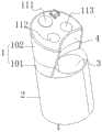
图1是本发明提供的内窥镜先端头的立体结构示意图之一;Fig. 1 is one of the schematic diagrams of the three-dimensional structure of the tip end of the endoscope provided by the present invention;
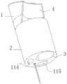
图2是本发明提供的内窥镜先端头的立体结构示意图之二;Fig. 2 is the second schematic view of the three-dimensional structure of the tip end of the endoscope provided by the present invention;
图3是本发明提供的内窥镜先端头在摆动段处于第一状态的主视结构示意图;Fig. 3 is a schematic diagram of the front view of the tip head of the endoscope provided by the present invention in the first state in the swing section;
图4是本发明提供的内窥镜先端头在摆动段处于第二状态的主视结构示意图;Fig. 4 is a schematic diagram of the front view of the tip head of the endoscope provided by the present invention in the second state in the swing section;
图5是本发明提供的采用第一种锁止组件的内窥镜先端头在摆动段处于第一状态的剖视结构示意图;Fig. 5 is a schematic cross-sectional structural view of the first state of the tip end of the endoscope adopting the first locking assembly provided by the present invention in the first state in the swing section;
图6是本发明提供的采用第一种锁止组件的内窥镜先端头在摆动段处于第二状态的剖视结构示意图;Fig. 6 is a schematic cross-sectional structural view of the tip end of the endoscope adopting the first locking assembly provided by the present invention in the second state in the swing section;
图7是本发明提供的采用第二种锁止组件的内窥镜先端头在摆动段处于第一状态的剖视结构示意图;Fig. 7 is a schematic cross-sectional structural view of the first state of the tip end of the endoscope adopting the second locking assembly provided by the present invention in the first state in the swing section;
图8是本发明提供的采用第二种锁止组件的内窥镜先端头在摆动段处于第二状态的剖视结构示意图;Fig. 8 is a schematic cross-sectional structural view of the tip end of the endoscope adopting the second locking assembly provided by the present invention in the second state in the swing section;
附图标记:Reference signs:
1:摆动段; 2:固定段; 3:工作钳道;1: Swing section; 2: Fixed section; 3: Working clamp channel;
4:凹槽; 5:锁止槽; 6:锁止臂;4: groove; 5: locking groove; 6: locking arm;
7:第一牵引件; 8:锁销; 9:弹性件;7: first traction member; 8: lock pin; 9: elastic member;
10:第一销孔; 11:第二销孔; 12:第二牵引件;10: first pin hole; 11: second pin hole; 12: second traction member;
13:限位槽; 14:限位臂; 101:可形变节段;13: limit groove; 14: limit arm; 101: deformable segment;
102:安装节段; 111:第一开孔; 112:第二开孔;102: installation segment; 111: first opening; 112: second opening;
113:第三开孔; 114:第一通道; 115:第二通道;113: the third opening; 114: the first channel; 115: the second channel;
21:第一区段; 22:第二区段。21: the first section; 22: the second section.
具体实施方式Detailed ways
为使本发明的目的、技术方案和优点更加清楚,下面将结合本发明中的附图,对本发明中的技术方案进行清楚、完整地描述,显然,所描述的实施例是本发明一部分实施例,而不是全部的实施例。基于本发明中的实施例,本领域普通技术人员在没有作出创造性劳动前提下所获得的所有其他实施例,都属于本发明保护的范围。In order to make the purpose, technical solutions and advantages of the present invention clearer, the technical solutions in the present invention will be clearly and completely described below in conjunction with the accompanying drawings in the present invention. Obviously, the described embodiments are part of the embodiments of the present invention , but not all examples. Based on the embodiments of the present invention, all other embodiments obtained by persons of ordinary skill in the art without creative efforts fall within the protection scope of the present invention.
下面结合图1-图8描述本发明的一种内窥镜先端头与内窥镜。An endoscope tip and an endoscope according to the present invention will be described below with reference to FIGS. 1-8 .
如图1至图4所示,本实施例提供一种内窥镜先端头,包括:摆动段1与固定段2;摆动段1、固定段2沿先端头的轴向设置;固定段2沿先端头的径向限定出第一区段21与第二区段22;摆动段1至少设有光学组件,摆动段1朝向固定段2的一端与第一区段21对应的端部连接,第二区段22至少设有沿轴向贯穿的工作钳道3;摆动段1能够沿径向在第一状态与第二状态之间切换,在摆动段1处于第一状态的情况下,摆动段1背离固定段2的一端靠近工作钳道3的出口端,在摆动段1处于第二状态的情况下,摆动段1背离固定段2的一端远离工作钳道3的出口端;固定段2用于与内窥镜的驱动部连接。As shown in Figures 1 to 4, this embodiment provides an endoscope tip, including: a
具体地,本实施例基于对现有先端头的改进,通过在对应固定段2的第一区段21的摆动段1布置光学组件,在固定段2的第二区段22设置工作钳道3,可在同等外径的条件下,在先端头内设置更大直径的工作钳道3,满足内窥镜更多的临床使用需求;与此同时,在控制先端头的摆动段1处于第一状态时,可使得摆动段1背离固定段2的一端靠近工作钳道3的出口端,以便于减轻内窥镜进出人体时对人体造成的不适,并在控制先端头的摆动段1处于第二状态时,可在工作钳道3的出口端提供充裕的避让空间,以便于手术器械的进出。Specifically, this embodiment is based on the improvement of the existing tip head, by arranging optical components in the
由此可见,本发明结构简单、可实施性高,实现了在先端头布置较大直径的工作钳道,不仅能够满足较多的临床使用需求,而且减轻了内窥镜进入人体时的不适感。It can be seen that the present invention has a simple structure and high implementability, and realizes the arrangement of a working forceps channel with a larger diameter at the tip, which can not only meet more clinical use requirements, but also reduce the discomfort when the endoscope enters the human body .
其中,本实施例所示的摆动段1可以是硬质结构的摆动段,摆动段1靠近固定段2的一端通过柔性连接结构与固定段2连接,以实现摆动段1的状态沿径向的切换;或者,摆动段1也可以是具有一定硬度的柔性结构或者可定型的变形结构,同样可实现摆动段1的状态沿径向的切换。Wherein, the oscillating
在实际应用中,当内窥镜先端头插入至人体内,并到达病灶位置后,由于内窥镜的驱动部的一端与固定段2远离摆动段1的一端连接,并能够控制内窥镜先端头朝向不同的方向弯曲,在控制摆动段1的状态沿径向的切换时,可将摆动段1背离固定段2的一端与病灶位置接触,通过驱动部对内窥镜先端头施加沿所述径向的外力,以使得摆动段1由第一状态切换至第二状态,或者由第二状态切换至第一状态。显然,上述外力的施力方向与摆动段1的摆动方向相反。In practical application, when the tip of the endoscope is inserted into the human body and reaches the location of the lesion, since one end of the drive part of the endoscope is connected to the end of the fixed
优选地,本实施例除了在摆动段1设置光学组件外,还可以在摆动段1设置输液通道,以满足内窥镜的其它功能需求。其中,光学组件可以包括本领域公知的摄像头与光源。Preferably, in this embodiment, in addition to providing optical components on the
如图1所示,本实施例可在摆动段1背离固定段2一端的端面构造第一开孔111、第二开孔112及第三开孔113,其中,第一开孔111用于布置摄像头,第一开孔111用于布置光源的出光端,第三开孔113用作出液口。As shown in Figure 1, in this embodiment, a
如图2所示,在摆动段1只设置有光学组件的情况下,本实施例可沿着摆动段1与固定段2的第一区段21设置相隔离的第一通道114与第二通道115,其中,第一通道114用于布置与摄像头对应的柔性线缆,第二通道115用于布置与出光端对应的柔性光缆。As shown in Figure 2, in the case where the
当然,本实施例也可沿着摆动段1与固定段2的第一区段21设置一个直通的腔体,在腔体内布置与光学组件对应的各类线缆。Of course, in this embodiment, a straight-through cavity can also be provided along the
如图1所示,为了便于手术器械进出工作钳道3,本实施例在摆动段1靠近第二区段22的一侧面构造有凹槽4,凹槽4沿摆动段1的轴向延伸,凹槽4优选为横截面为圆弧形的凹槽。As shown in Figure 1, in order to facilitate the entry and exit of surgical instruments into and out of the working
如图3所示,为了减轻内窥镜进入人体时对人体造成的不适,在摆动段1处于第一状态的情况下,本实施例设置摆动段1沿轴向在固定段2的端面上的投影位于固定段2的端面所在的区域内,即摆动段1在固定段2的端面上的投影面积小于固定段2的端面的面积,这不仅便于内窥镜先端头在人体内的插入与取出,而且在摆动段1处于第一状态时,摆动段1靠近第二区段22的一侧面对工作钳道3的出口端形成遮挡,可在内窥镜先端头向人体插入过程中,减小异物进入至工作钳道3内。As shown in Figure 3, in order to alleviate the discomfort caused to the human body when the endoscope enters the human body, when the swinging
其中,在摆动段1处于第一状态时,凹槽4的延伸方向与固定段2的端面所呈的夹角为锐角,例如,该锐角的大小可以为45°-75°。Wherein, when the swinging
如图4所示,在摆动段1处于第二状态的情况下,凹槽4的延伸方向相对于固定段2的端面为直角或钝角。As shown in FIG. 4 , when the swinging
其中,本实施例在图4中具体示意了在摆动段1处于第二状态时,凹槽4的延伸方向相对于固定段2的端面为直角。此时,凹槽4的内壁面与工作钳道3的部分内壁面共面。如此,本实施例在摆动段1处于第二状态时,可解除对工作钳道3的出口端形成的遮挡,便于控制手术器械进出工作钳道3。在此,本实施例所示的凹槽4作为工作钳道3的延伸通道,可对手术器械的进出起到引导作用。Wherein, this embodiment specifically shows in FIG. 4 that when the swinging
当然,本实施例还可设置在摆动段1处于第二状态的情况下,凹槽4的延伸方向相对于固定段2的端面为钝角,以进一步增大工作钳道3的出口端的前侧的操作空间,在控制手术器械进出工作钳道3的同时,还便于对病灶位置进行手术治疗。Of course, in this embodiment, when the
如图1所示,为了便于灵敏地控制摆动段1沿所述径向摆动,本实施例将摆动段1分设为可形变节段101与安装节段102;本实施例将固定段2的第一区段21对应的端部与可形变节段101的一端连接,可形变节段101的另一端与安装节段102的一端连接,并在安装节段102内安装光学组件。As shown in Figure 1, in order to control the swinging
在此,本实施例所示的可形变节段101随着安装节段102的位置的切换进行相应地变形。基于可形变节段101的设置,既便捷地实现了安装节段102的位置切换,又确保了内窥镜体的密封。其中,可形变节段101可以为硅胶制成的节段,安装节段102可以为硬质的塑料材料制成的节段。Here, the
进一步地,为了便于基于可形变节段101与安装节段102,较好地控制摆动段1在第一状态与第二状态之间切换,本实施例所示的可形变节段101包括第一侧壁与第二侧壁,第一侧壁与第二侧壁沿径向相对设置,第一侧壁远离第二区段22,第二侧壁靠近第二区段22;第一侧壁的抗形变能力小于或等于第二侧壁的抗形变能力;或者,第一侧壁在第一状态下的压缩量小于在第二状态下的压缩量。Furthermore, in order to better control the switching between the first state and the second state of the
基于上述实施例所示的方案,本实施例还设置有锁止组件;锁止组件设于摆动段1与固定段2之间,锁止组件用于将摆动段1锁定于第一状态或第二状态。Based on the solutions shown in the above embodiments, this embodiment is also provided with a locking assembly; the locking assembly is arranged between the
在一个优选实施例中,如图5与图6所示,锁止组件包括:锁止槽5、锁止臂6及第一牵引件7;锁止槽5设于第一区段21朝向摆动段1的一端;锁止臂6的一端与摆动段1连接,另一端伸入至锁止槽5中;锁止臂6的另一端与锁止槽5相适配,并构成球形万向节;第一牵引件7的一端与摆动段1连接,第一牵引件7沿内窥镜先端头的轴向延伸。In a preferred embodiment, as shown in Figure 5 and Figure 6, the locking assembly includes: a locking
在此,本实施例可设置摆动段1在常态下处于第一状态,基于第一牵引件7对摆动段1施加的牵引力作用,可在摆动段1处于第一状态时,控制第一摩擦面与第二摩擦面相抵接,从而将摆动段1锁止于第一状态。Here, in this embodiment, the
为了将摆动段1锁定于第二状态,本实施例在锁止臂6的另一端设有第一摩擦面,锁止槽5的内壁面设有第二摩擦面,则在摆动段1处于第二状态的情况下,通过对第一牵引件7施加拉持力,可使得第一摩擦面与第二摩擦面抵接,以使得锁止槽5与锁止臂6之间处于过盈配合状态,确保摆动段1能够维持在第二状态。In order to lock the
相应地,为了便于对摆动段1进行状态切换控制,在控制摆动段1在第一状态与第二状态之间时,只需松弛第一牵引件7,使得第一摩擦面与第二摩擦面处于间隙配合状态,可通过外力控制摆动段1朝向或背离第二区段22的一侧摆动。Correspondingly, in order to facilitate the state switching control of the
其中,本实施例所示的第一摩擦面与第二摩擦面均可以为分布有多个齿纹的齿纹面;第一摩擦面可以是带有多个细小的凸起的粗糙面,第二摩擦面相应地为带有多个细小的凹坑的粗糙面,在第一摩擦面与第二摩擦面抵接时,多个凸起能够嵌入至多个凹坑中。Wherein, both the first friction surface and the second friction surface shown in this embodiment may be a tooth surface distributed with a plurality of tooth lines; the first friction surface may be a rough surface with a plurality of fine protrusions, the second The two friction surfaces are correspondingly rough surfaces with a plurality of fine pits, and when the first friction surface and the second friction surface abut, the plurality of protrusions can be embedded into the plurality of pits.
在另一个优选实施例中,如图7与图8所示,锁止组件包括:锁销8、弹性件9、第一销孔10、第二销孔11及第二牵引件12;锁销8与弹性件9设于第一区段21,弹性件9连接于锁销8与固定段2之间,以控制锁销8沿固定段2的轴向往复运动,第二牵引件12的一端与锁销8连接,第二牵引件12沿固定段2的轴向延伸;第一销孔10与第二销孔11分别设于摆动段1;在摆动段1处于第一状态的情况下,锁销8伸入至第一销孔10中,在摆动段1处于第二状态的情况下,锁销8伸入至第二销孔11中。In another preferred embodiment, as shown in Figure 7 and Figure 8, the locking assembly includes: a locking
在此,本实施例所示的第一销孔10的开口端与第二销孔11的开口端相靠近,第一销孔10的中轴线与第二销孔11中轴线呈锐角。Here, the open end of the
为了便于控制锁销8沿固定段2的轴向往复运动,本实施例在固定段2构造有导向孔,导向孔包括第一孔段、第二孔段及第三孔段,第一孔段、第二孔段及第三孔段依次连通;相应地,锁销8包括第一段、第二段及第三段,第一段、第二段及第三段依次连接,第二段的直径分别大于第一段的直径与第三段的直径;第一段的部分结构可移动地设于第一孔段,第二段能够在第二孔段内移动,并与第二孔段相适配;第三段的部分结构可移动地设于第三孔段,第一孔段的内径与第三孔的内径均小于第二孔段的内径。第二牵引件12的一端与锁销8的第三段远离第二段的一端连接。In order to facilitate the control of the axial reciprocating movement of the
与此同时,本实施例所示的弹性件9优选为弹簧,弹簧套设于锁销8的第三段,锁销8的第二段朝向第三端的一端与弹簧的一端连接,第二孔段与第三孔段之间的台阶面与弹簧的另一端连接。At the same time, the
如图7所示,在摆动段1处于第一状态时,锁销8的第一段伸入至第一销孔10中,可将摆动段1锁定于第一状态;如图8所示,在将摆动段1从第一状态切换至第二状态时,可先对第二牵引件12施加拉持力,使得锁销8与第一销孔10分离;然后,在通过外力将摆动段1切换至第二状态时,只需松开第二牵引件12,锁销8可在弹簧的回复力的作用下自动插入至第二销孔11中,以将摆动段1锁定于第二状态。As shown in Figure 7, when the
进一步地,为了便于对摆动段1摆动的位置进行精确地控制,本实施例所示的内窥镜先端头还设置有限位组件;限位组件包括:限位槽13与限位臂14;限位槽13的第一槽壁与第二槽壁沿径向相对,第一槽壁远离第二区段22,第二槽壁靠近第二区段22。Further, in order to facilitate the precise control of the swinging position of the
在一个实施例中,如图5与图6所示,本实施例所示的限位槽13设于固定段2,限位槽13的槽口朝向摆动段1,限位臂14的一端与摆动段1连接,另一端伸入至限位槽13内。在此,本实施例所示的限位臂14可以为上述实施例所示的锁止臂6,上述实施例所示的锁止槽5设于限位槽13的槽底。In one embodiment, as shown in FIG. 5 and FIG. 6 , the limiting
如图5所示,在摆动段1处于第一状态的情况下,限位臂14与限位槽13的第二槽壁抵接,以阻挡摆动段1继续朝向靠近固定段2的第二区段22的一侧摆动。如图6所示,在摆动段1处于第二状态的情况下,限位臂14与限位槽13的第一槽壁抵接,以阻挡摆动段1继续朝向远离固定段2的第二区段22的一侧摆动。As shown in FIG. 5 , when the
在另一个实施例中,如图7与图8所示,本实施例所示的限位槽13设于摆动段1,限位槽13的槽口朝向固定段2,限位臂14的一端与固定段2连接,另一端伸入至限位槽13内。In another embodiment, as shown in FIG. 7 and FIG. 8 , the limiting
如图7所示,在摆动段1处于第一状态的情况下,限位臂14与限位槽13的第一槽壁抵接,以阻挡摆动段1继续朝向靠近固定段2的第二区段22的一侧摆动。如图8所示,在摆动段1处于第二状态的情况下,限位臂14与限位槽13的第二槽壁抵接,以阻挡摆动段1继续朝向远离固定段2的第二区段22的一侧摆动。As shown in FIG. 7 , when the
优选地,本实施例还提供一种内窥镜,包括:驱动部,还包括如上任一项所述的内窥镜先端头,驱动部的一端与内窥镜先端头连接,以驱动内窥镜先端头朝向不同的方向弯曲。Preferably, this embodiment also provides an endoscope, including: a driving part, and also includes the tip of the endoscope as described in any one of the above items, one end of the driving part is connected with the tip of the endoscope to drive the endoscope The mirror tip is bent in different directions.
具体地,由于本实施例所示的内窥镜包括了内窥镜先端头,内窥镜先端头的具体结构参照上述实施例,则本实施例所示的内窥镜包括了上述实施例的全部技术方案,因此,至少具有上述实施例的全部技术方案所带来的所有有益效果,在此不再一一赘述。Specifically, since the endoscope shown in this embodiment includes the tip of the endoscope, and the specific structure of the tip of the endoscope refers to the above-mentioned embodiment, the endoscope shown in this embodiment includes the tip of the above-mentioned embodiment. All technical solutions, therefore, at least have all the beneficial effects brought by all the technical solutions of the above embodiments, and will not be repeated here.
最后应说明的是:以上实施例仅用以说明本发明的技术方案,而非对其限制;尽管参照前述实施例对本发明进行了详细的说明,本领域的普通技术人员应当理解:其依然可以对前述各实施例所记载的技术方案进行修改,或者对其中部分技术特征进行等同替换;而这些修改或者替换,并不使相应技术方案的本质脱离本发明各实施例技术方案的精神和范围。Finally, it should be noted that: the above embodiments are only used to illustrate the technical solutions of the present invention, rather than to limit them; although the present invention has been described in detail with reference to the foregoing embodiments, those of ordinary skill in the art should understand that: it can still be Modifications are made to the technical solutions described in the foregoing embodiments, or equivalent replacements are made to some of the technical features; and these modifications or replacements do not make the essence of the corresponding technical solutions deviate from the spirit and scope of the technical solutions of the various embodiments of the present invention.
Claims (10)
Translated fromChinesePriority Applications (1)
| Application Number | Priority Date | Filing Date | Title |
|---|---|---|---|
| CN202111667985.XACN116407061A (en) | 2021-12-31 | 2021-12-31 | Endoscope tip head and endoscope |
Applications Claiming Priority (1)
| Application Number | Priority Date | Filing Date | Title |
|---|---|---|---|
| CN202111667985.XACN116407061A (en) | 2021-12-31 | 2021-12-31 | Endoscope tip head and endoscope |
Publications (1)
| Publication Number | Publication Date |
|---|---|
| CN116407061Atrue CN116407061A (en) | 2023-07-11 |
Family
ID=87048309
Family Applications (1)
| Application Number | Title | Priority Date | Filing Date |
|---|---|---|---|
| CN202111667985.XAPendingCN116407061A (en) | 2021-12-31 | 2021-12-31 | Endoscope tip head and endoscope |
Country Status (1)
| Country | Link |
|---|---|
| CN (1) | CN116407061A (en) |
Cited By (1)
| Publication number | Priority date | Publication date | Assignee | Title |
|---|---|---|---|---|
| CN120167874A (en)* | 2025-05-23 | 2025-06-20 | 安忻(成都)医疗科技发展有限责任公司 | Hysteroscopic endoscope and method of using the same |
Citations (9)
| Publication number | Priority date | Publication date | Assignee | Title |
|---|---|---|---|---|
| US20080108869A1 (en)* | 2006-10-20 | 2008-05-08 | Femsuite Llc | Optical surgical device and methods of use |
| US20110098529A1 (en)* | 2009-10-28 | 2011-04-28 | Boston Scientific Scimed, Inc. | Method and Apparatus Related to a Flexible Assembly at a Distal End Portion of a Medical Device |
| CN202739969U (en)* | 2012-09-25 | 2013-02-20 | 孙庆文 | Novel gastroscope |
| US20180055347A1 (en)* | 2015-04-13 | 2018-03-01 | Nelson Jorge TEIXEIRA DOS SANTOS PAULO | Device for intra-cardiac and intra-vascular surgical procedure having an endoluminal ultrasound probe |
| CN111728694A (en)* | 2020-05-22 | 2020-10-02 | 江苏霆升科技有限公司 | Method for real-time spatial positioning of ablation catheter in heart cavity by utilizing ultrasound |
| CN113616356A (en)* | 2021-08-24 | 2021-11-09 | 山东曙星医疗科技有限公司 | Multi-angle adjusting and fixing device |
| CN214805720U (en)* | 2021-01-27 | 2021-11-23 | 遂宁市中心医院 | Acetabular bone grafting fixing device |
| CN214889905U (en)* | 2021-04-16 | 2021-11-26 | 天津睿信康达科技发展有限公司 | Make things convenient for angle regulation's surveillance camera head support freely |
| CN220745154U (en)* | 2023-07-14 | 2024-04-09 | 中建筑港集团有限公司 | Auxiliary centering device for convenient ground component |
- 2021
- 2021-12-31CNCN202111667985.XApatent/CN116407061A/enactivePending
Patent Citations (9)
| Publication number | Priority date | Publication date | Assignee | Title |
|---|---|---|---|---|
| US20080108869A1 (en)* | 2006-10-20 | 2008-05-08 | Femsuite Llc | Optical surgical device and methods of use |
| US20110098529A1 (en)* | 2009-10-28 | 2011-04-28 | Boston Scientific Scimed, Inc. | Method and Apparatus Related to a Flexible Assembly at a Distal End Portion of a Medical Device |
| CN202739969U (en)* | 2012-09-25 | 2013-02-20 | 孙庆文 | Novel gastroscope |
| US20180055347A1 (en)* | 2015-04-13 | 2018-03-01 | Nelson Jorge TEIXEIRA DOS SANTOS PAULO | Device for intra-cardiac and intra-vascular surgical procedure having an endoluminal ultrasound probe |
| CN111728694A (en)* | 2020-05-22 | 2020-10-02 | 江苏霆升科技有限公司 | Method for real-time spatial positioning of ablation catheter in heart cavity by utilizing ultrasound |
| CN214805720U (en)* | 2021-01-27 | 2021-11-23 | 遂宁市中心医院 | Acetabular bone grafting fixing device |
| CN214889905U (en)* | 2021-04-16 | 2021-11-26 | 天津睿信康达科技发展有限公司 | Make things convenient for angle regulation's surveillance camera head support freely |
| CN113616356A (en)* | 2021-08-24 | 2021-11-09 | 山东曙星医疗科技有限公司 | Multi-angle adjusting and fixing device |
| CN220745154U (en)* | 2023-07-14 | 2024-04-09 | 中建筑港集团有限公司 | Auxiliary centering device for convenient ground component |
Cited By (1)
| Publication number | Priority date | Publication date | Assignee | Title |
|---|---|---|---|---|
| CN120167874A (en)* | 2025-05-23 | 2025-06-20 | 安忻(成都)医疗科技发展有限责任公司 | Hysteroscopic endoscope and method of using the same |
Similar Documents
| Publication | Publication Date | Title |
|---|---|---|
| US5377668A (en) | Apparatus and method for endoscopic diagnostics and therapy | |
| JP4615906B2 (en) | Endoscope and endoscope bending operation auxiliary member | |
| US20020183595A1 (en) | Medical body access device | |
| CN118434344A (en) | Endoscope with movable front end | |
| CN102123653A (en) | Treating endoscope | |
| JP6497785B2 (en) | Disposable sheath for endotracheal intubation device | |
| CN115969295A (en) | Stiffness adjustment mechanism of composite insertion part of endoscope and endoscope | |
| WO2024222977A1 (en) | Introducer sheath with bendable distal end, and ureteroscope and method for using same | |
| CN115104996A (en) | Self-adaptive bending tube, bending tube for endoscope and endoscope | |
| CN215687669U (en) | Endoscope lift pincers ware, endoscope head end and endoscope | |
| CN118892297B (en) | Active bending section, insertion portion and endoscope | |
| JP2019522545A (en) | Adapter for multiple types of endoscopes | |
| CN116407061A (en) | Endoscope tip head and endoscope | |
| JP3325103B2 (en) | Cover-type endoscope | |
| CN113164020A (en) | Channel unit for endoscope and endoscope | |
| CN116407070A (en) | Endoscope working channel assembly and endoscope | |
| US20210068637A1 (en) | Endoscope and channel tube | |
| JP3394607B2 (en) | Side-view type cover endoscope | |
| CN118285732A (en) | Image acquisition method, endoscope, insertion device for endoscope, and front end cover assembly | |
| CN110090065B (en) | Chuck release pincers | |
| JP4145464B2 (en) | Remote microsurgery system and slave manipulator insertion method. | |
| CN117243547A (en) | Snake bone structure and endoscope | |
| CN111132597B (en) | Insertion aid system | |
| CN216256996U (en) | Self-adaptive bending tube, bending tube for endoscope and endoscope | |
| JP4177020B2 (en) | Endoscope |
Legal Events
| Date | Code | Title | Description |
|---|---|---|---|
| PB01 | Publication | ||
| PB01 | Publication | ||
| SE01 | Entry into force of request for substantive examination | ||
| SE01 | Entry into force of request for substantive examination |