CN116399883A - A multi-degree-of-freedom detection device for an optical element - Google Patents
A multi-degree-of-freedom detection device for an optical elementDownload PDFInfo
- Publication number
- CN116399883A CN116399883ACN202310579864.2ACN202310579864ACN116399883ACN 116399883 ACN116399883 ACN 116399883ACN 202310579864 ACN202310579864 ACN 202310579864ACN 116399883 ACN116399883 ACN 116399883A
- Authority
- CN
- China
- Prior art keywords
- plate
- placement
- optical element
- fixed
- degree
- Prior art date
- Legal status (The legal status is an assumption and is not a legal conclusion. Google has not performed a legal analysis and makes no representation as to the accuracy of the status listed.)
- Pending
Links
Images


Classifications
- G—PHYSICS
- G01—MEASURING; TESTING
- G01N—INVESTIGATING OR ANALYSING MATERIALS BY DETERMINING THEIR CHEMICAL OR PHYSICAL PROPERTIES
- G01N21/00—Investigating or analysing materials by the use of optical means, i.e. using sub-millimetre waves, infrared, visible or ultraviolet light
- G01N21/84—Systems specially adapted for particular applications
- G01N21/88—Investigating the presence of flaws or contamination
- G01N21/95—Investigating the presence of flaws or contamination characterised by the material or shape of the object to be examined
- B—PERFORMING OPERATIONS; TRANSPORTING
- B25—HAND TOOLS; PORTABLE POWER-DRIVEN TOOLS; MANIPULATORS
- B25B—TOOLS OR BENCH DEVICES NOT OTHERWISE PROVIDED FOR, FOR FASTENING, CONNECTING, DISENGAGING OR HOLDING
- B25B11/00—Work holders not covered by any preceding group in the subclass, e.g. magnetic work holders, vacuum work holders
- F—MECHANICAL ENGINEERING; LIGHTING; HEATING; WEAPONS; BLASTING
- F16—ENGINEERING ELEMENTS AND UNITS; GENERAL MEASURES FOR PRODUCING AND MAINTAINING EFFECTIVE FUNCTIONING OF MACHINES OR INSTALLATIONS; THERMAL INSULATION IN GENERAL
- F16M—FRAMES, CASINGS OR BEDS OF ENGINES, MACHINES OR APPARATUS, NOT SPECIFIC TO ENGINES, MACHINES OR APPARATUS PROVIDED FOR ELSEWHERE; STANDS; SUPPORTS
- F16M11/00—Stands or trestles as supports for apparatus or articles placed thereon ; Stands for scientific apparatus such as gravitational force meters
- F16M11/02—Heads
- F16M11/04—Means for attachment of apparatus; Means allowing adjustment of the apparatus relatively to the stand
- F16M11/043—Allowing translations
- F16M11/045—Allowing translations adapted to left-right translation movement
- F—MECHANICAL ENGINEERING; LIGHTING; HEATING; WEAPONS; BLASTING
- F16—ENGINEERING ELEMENTS AND UNITS; GENERAL MEASURES FOR PRODUCING AND MAINTAINING EFFECTIVE FUNCTIONING OF MACHINES OR INSTALLATIONS; THERMAL INSULATION IN GENERAL
- F16M—FRAMES, CASINGS OR BEDS OF ENGINES, MACHINES OR APPARATUS, NOT SPECIFIC TO ENGINES, MACHINES OR APPARATUS PROVIDED FOR ELSEWHERE; STANDS; SUPPORTS
- F16M11/00—Stands or trestles as supports for apparatus or articles placed thereon ; Stands for scientific apparatus such as gravitational force meters
- F16M11/02—Heads
- F16M11/04—Means for attachment of apparatus; Means allowing adjustment of the apparatus relatively to the stand
- F16M11/043—Allowing translations
- F16M11/046—Allowing translations adapted to upward-downward translation movement
- F—MECHANICAL ENGINEERING; LIGHTING; HEATING; WEAPONS; BLASTING
- F16—ENGINEERING ELEMENTS AND UNITS; GENERAL MEASURES FOR PRODUCING AND MAINTAINING EFFECTIVE FUNCTIONING OF MACHINES OR INSTALLATIONS; THERMAL INSULATION IN GENERAL
- F16M—FRAMES, CASINGS OR BEDS OF ENGINES, MACHINES OR APPARATUS, NOT SPECIFIC TO ENGINES, MACHINES OR APPARATUS PROVIDED FOR ELSEWHERE; STANDS; SUPPORTS
- F16M11/00—Stands or trestles as supports for apparatus or articles placed thereon ; Stands for scientific apparatus such as gravitational force meters
- F16M11/02—Heads
- F16M11/04—Means for attachment of apparatus; Means allowing adjustment of the apparatus relatively to the stand
- F16M11/043—Allowing translations
- F16M11/048—Allowing translations adapted to forward-backward translation movement
- F—MECHANICAL ENGINEERING; LIGHTING; HEATING; WEAPONS; BLASTING
- F16—ENGINEERING ELEMENTS AND UNITS; GENERAL MEASURES FOR PRODUCING AND MAINTAINING EFFECTIVE FUNCTIONING OF MACHINES OR INSTALLATIONS; THERMAL INSULATION IN GENERAL
- F16M—FRAMES, CASINGS OR BEDS OF ENGINES, MACHINES OR APPARATUS, NOT SPECIFIC TO ENGINES, MACHINES OR APPARATUS PROVIDED FOR ELSEWHERE; STANDS; SUPPORTS
- F16M11/00—Stands or trestles as supports for apparatus or articles placed thereon ; Stands for scientific apparatus such as gravitational force meters
- F16M11/02—Heads
- F16M11/18—Heads with mechanism for moving the apparatus relatively to the stand
- G—PHYSICS
- G01—MEASURING; TESTING
- G01N—INVESTIGATING OR ANALYSING MATERIALS BY DETERMINING THEIR CHEMICAL OR PHYSICAL PROPERTIES
- G01N21/00—Investigating or analysing materials by the use of optical means, i.e. using sub-millimetre waves, infrared, visible or ultraviolet light
- G01N21/01—Arrangements or apparatus for facilitating the optical investigation
- G—PHYSICS
- G01—MEASURING; TESTING
- G01N—INVESTIGATING OR ANALYSING MATERIALS BY DETERMINING THEIR CHEMICAL OR PHYSICAL PROPERTIES
- G01N21/00—Investigating or analysing materials by the use of optical means, i.e. using sub-millimetre waves, infrared, visible or ultraviolet light
- G01N21/84—Systems specially adapted for particular applications
- G01N21/88—Investigating the presence of flaws or contamination
- G01N21/95—Investigating the presence of flaws or contamination characterised by the material or shape of the object to be examined
- G01N21/958—Inspecting transparent materials or objects, e.g. windscreens
- G—PHYSICS
- G01—MEASURING; TESTING
- G01N—INVESTIGATING OR ANALYSING MATERIALS BY DETERMINING THEIR CHEMICAL OR PHYSICAL PROPERTIES
- G01N21/00—Investigating or analysing materials by the use of optical means, i.e. using sub-millimetre waves, infrared, visible or ultraviolet light
- G01N21/84—Systems specially adapted for particular applications
- G01N21/88—Investigating the presence of flaws or contamination
- G01N21/95—Investigating the presence of flaws or contamination characterised by the material or shape of the object to be examined
- G01N2021/9511—Optical elements other than lenses, e.g. mirrors
- G—PHYSICS
- G01—MEASURING; TESTING
- G01N—INVESTIGATING OR ANALYSING MATERIALS BY DETERMINING THEIR CHEMICAL OR PHYSICAL PROPERTIES
- G01N21/00—Investigating or analysing materials by the use of optical means, i.e. using sub-millimetre waves, infrared, visible or ultraviolet light
- G01N21/84—Systems specially adapted for particular applications
- G01N21/88—Investigating the presence of flaws or contamination
- G01N21/95—Investigating the presence of flaws or contamination characterised by the material or shape of the object to be examined
- G01N21/958—Inspecting transparent materials or objects, e.g. windscreens
- G01N2021/9583—Lenses
- Y—GENERAL TAGGING OF NEW TECHNOLOGICAL DEVELOPMENTS; GENERAL TAGGING OF CROSS-SECTIONAL TECHNOLOGIES SPANNING OVER SEVERAL SECTIONS OF THE IPC; TECHNICAL SUBJECTS COVERED BY FORMER USPC CROSS-REFERENCE ART COLLECTIONS [XRACs] AND DIGESTS
- Y02—TECHNOLOGIES OR APPLICATIONS FOR MITIGATION OR ADAPTATION AGAINST CLIMATE CHANGE
- Y02E—REDUCTION OF GREENHOUSE GAS [GHG] EMISSIONS, RELATED TO ENERGY GENERATION, TRANSMISSION OR DISTRIBUTION
- Y02E10/00—Energy generation through renewable energy sources
- Y02E10/50—Photovoltaic [PV] energy
Landscapes
- Engineering & Computer Science (AREA)
- General Engineering & Computer Science (AREA)
- Mechanical Engineering (AREA)
- General Health & Medical Sciences (AREA)
- Analytical Chemistry (AREA)
- Biochemistry (AREA)
- Physics & Mathematics (AREA)
- General Physics & Mathematics (AREA)
- Immunology (AREA)
- Pathology (AREA)
- Chemical & Material Sciences (AREA)
- Life Sciences & Earth Sciences (AREA)
- Health & Medical Sciences (AREA)
- Details Of Measuring And Other Instruments (AREA)
- Automatic Focus Adjustment (AREA)
Abstract
Description
Translated fromChinese技术领域technical field
本发明涉及光学元件检测技术领域,特别涉及一种光学元件多自由度检测装置。The invention relates to the technical field of optical element detection, in particular to an optical element multi-degree-of-freedom detection device.
背景技术Background technique
光学元件,是光学系统的基本组成单元。大部分光学零件起成像的作用,如透镜、棱镜、反射镜等。另外还有一些在光学系统中起特殊作用(如分光、传像、滤波等)的零件,如分划板、滤光片、光栅用以光学纤维件等。全息透镜、梯度折射率透镜、二元光学元件等,是一二十年来出现的新型光学零件。Optical components are the basic unit of an optical system. Most of the optical components play the role of imaging, such as lenses, prisms, mirrors, etc. In addition, there are some parts that play special roles in the optical system (such as light splitting, image transmission, filtering, etc.), such as reticle, optical filter, grating for optical fiber parts, etc. Holographic lenses, gradient index lenses, and binary optical elements are new types of optical components that have emerged in the past ten or twenty years.
光学元件在生产完成后一般都会进行质检,质检包括对光学元件外表面完整性的检测,避免光学元件表面出现破损等情况,光学元件表面缺陷是表面质量的重要指标,在紫外/极紫外光学系统、大功率激光等光学系统中,对该指标均有严格要求。After the production of optical components is completed, quality inspection is generally carried out. Quality inspection includes the detection of the integrity of the outer surface of optical components to avoid damage to the surface of optical components. Surface defects of optical components are important indicators of surface quality. In the ultraviolet/extreme ultraviolet In optical systems such as optical systems and high-power lasers, there are strict requirements on this index.
目前,对该指标的检测手段极为有限,传统中多采用暗室法检测,但存在判读不准确、受人为影响大、无法长时间检测等缺点。市场上成熟的检测仪器也较为少见,多数产品与文献中主要基于单镜头加运动机构的方案。即选取合适的显微镜头,并配套运动机构带动镜头沿光学元件表面进行扫描,扫描得到的图像经后续分析处理以获得表面缺陷数据。但是这种方案实现难度较大,因为光学表面缺陷的小尺度决定了镜头的放大倍数,而满足放大倍数的镜头景深都比较小(几微米到几十微米),镜头的小景深又决定了运动机构的高精度,高精度运动机构价格昂贵,且会带来一系列复杂问题。以上原因导致该方案存在技术难度大、成本高,难以实现的缺点,且难以检测球面、非球面等大矢高元件。At present, the detection methods for this indicator are extremely limited. Traditionally, the darkroom method is used for detection, but there are shortcomings such as inaccurate interpretation, large human influence, and inability to detect for a long time. Mature testing instruments on the market are also relatively rare, and most products and literature are mainly based on a single-lens plus motion mechanism solution. That is to select a suitable microscope lens, and a supporting motion mechanism drives the lens to scan along the surface of the optical element, and the scanned image is subsequently analyzed and processed to obtain surface defect data. However, this solution is difficult to implement, because the small scale of optical surface defects determines the magnification of the lens, and the depth of field of the lens that meets the magnification is relatively small (a few microns to tens of microns), and the small depth of field of the lens determines the motion. The high precision of the mechanism, the high precision motion mechanism is expensive, and will bring a series of complicated problems. Due to the above reasons, this solution has the disadvantages of high technical difficulty, high cost, and difficulty in realization, and it is difficult to detect large components such as spherical surfaces and aspheric surfaces.
因此,有必要提供一种光学元件多自由度检测装置解决上述技术问题。Therefore, it is necessary to provide an optical element multi-degree-of-freedom detection device to solve the above technical problems.
发明内容Contents of the invention
为解决上述技术问题,本发明提供一种光学元件多自由度检测装置。In order to solve the above technical problems, the present invention provides a multi-degree-of-freedom detection device for optical elements.
本发明提供的一种光学元件多自由度检测装置,包括:可用于放置光学元件的光学平台,CCD摄像机,可将CCD摄像机上下移动的运动台,所述CCD摄像机通过线路连接可对图像处理的图像处理装置;A multi-degree-of-freedom detection device for an optical element provided by the present invention includes: an optical platform that can be used to place optical elements, a CCD camera, and a motion platform that can move the CCD camera up and down. image processing device;
所述光学平台包括放置台,所述放置台的顶部设有放置槽,所述放置槽的内部设有左固定板与右固定板,所述左固定板与右固定板分别固定连接左电动液压装置与右电动液压装置的伸缩端,所述左电动液压装置的固定端安装在放置台一端的内部,所述右电动液压装置的固定端安装在放置台另一端的内部;The optical table includes a placement platform, the top of the placement platform is provided with a placement slot, and the inside of the placement slot is provided with a left fixing plate and a right fixing plate, and the left fixing plate and the right fixing plate are respectively fixedly connected to the left electro-hydraulic The telescopic end of the device and the right electro-hydraulic device, the fixed end of the left electro-hydraulic device is installed inside one end of the placement table, and the fixed end of the right electro-hydraulic device is installed inside the other end of the placement table;
所述运动台包括固定架,所述固定架固定在放置台一侧的地面上,所述固定架的内壁之间安装有可上下移动的纵向电动滑轨,所述纵向电动滑轨通过纵向滑块滑动连接可左右移动的横向电动滑轨,所述横向电动滑轨通过横向滑块滑动连接可前后移动的前向电动滑轨,所述前向电动滑轨通过前向滑块连接转动机构,所述CCD摄像机安装在转动机构上;The moving platform includes a fixed frame, which is fixed on the ground on one side of the platform, and a longitudinal electric slide rail that can move up and down is installed between the inner walls of the fixed frame. The block is slidably connected to the horizontal electric slide rail that can move left and right, and the horizontal electric slide rail is slidably connected to the forward electric slide rail that can move back and forth through the horizontal slide block, and the forward electric slide rail is connected to the rotation mechanism through the forward slide block, The CCD camera is installed on the rotating mechanism;
优选的,所述转动机构包括转动板,所述转动板固定连接转轴,所述转轴通过联轴器旋转连接旋转电机,所述旋转电机安装在前向滑块上,所述CCD摄像机安装在转动板上。Preferably, the rotating mechanism includes a rotating plate, the rotating plate is fixedly connected to the rotating shaft, and the rotating shaft is connected to the rotating motor through a coupling, the rotating motor is installed on the forward slider, and the CCD camera is installed on the rotating board.
优选的,所述放置台的顶部设有第二放置槽,所述第二放置槽内部安装有放置板,所述放置板的顶部设有吸附孔,所述吸附孔通过气管连接真空泵,所述真空泵安装在第二放置槽的内部。Preferably, the top of the placement platform is provided with a second placement tank, and a placement plate is installed inside the second placement slot, and the top of the placement plate is provided with an adsorption hole, and the adsorption hole is connected to a vacuum pump through an air pipe. The vacuum pump is installed inside the second placement tank.
优选的,所述放置板的底部固定连接电动升降杆的伸缩端,所述电动升降杆的固定端安装在第二放置槽内部的底端。Preferably, the bottom of the placement plate is fixedly connected to the telescopic end of the electric lifting rod, and the fixed end of the electric lifting rod is installed at the bottom end inside the second placement slot.
优选的,所述放置板两端端面固定连接左滑块与右滑块,所述左滑块与右滑块分别滑动连接左滑槽与右滑槽,所述左滑槽与右滑槽分别设置在左支撑板与右支撑板的端面上,所述左支撑板与右支撑板的底部安装在第二放置槽内部的底端。Preferably, the two ends of the placement plate are fixedly connected to the left slider and the right slider, and the left slider and the right slider are respectively slidably connected to the left chute and the right chute, and the left chute and the right chute are respectively It is arranged on the end surfaces of the left support plate and the right support plate, and the bottoms of the left support plate and the right support plate are installed at the bottom end inside the second placement groove.
优选的,所述放置槽的内部安装有前固定板,所述前固定板的端面固定连接前电动液压装置的伸缩端,所述前电动液压装置的固定端安装在放置台的内部。Preferably, a front fixing plate is installed inside the placement tank, the end surface of the front fixing plate is fixedly connected to the telescopic end of the front electro-hydraulic device, and the fixed end of the front electro-hydraulic device is installed inside the placement platform.
优选的,所述放置槽两侧分别设有上左板与上右板,所述上左板与上右板分别固定连接上左电动液压装置与上右电动液压装置的伸缩端,所述上左电动液压装置与上右电动液压装置的固定端分别固定连接上左支撑板与上右支撑板,所述上左支撑板与上右支撑板的底部分别固定连接放置台的两端的端面。Preferably, an upper left plate and an upper right plate are respectively provided on both sides of the placement groove, and the upper left plate and the upper right plate are respectively fixedly connected to the telescopic ends of the upper left electro-hydraulic device and the upper right electro-hydraulic device. The fixed ends of the left electro-hydraulic device and the upper right electro-hydraulic device are respectively fixedly connected to the upper left support plate and the upper right support plate, and the bottoms of the upper left support plate and the upper right support plate are respectively fixedly connected to the end faces of the two ends of the placing platform.
优选的,所述横向电动滑轨的两端分别固定连接左滑杆与右滑杆,所述左滑杆与右滑杆分别滑动连接左限位槽与右限位槽,所述左限位槽与右限位槽分别滑动连接固定架内壁的两端。Preferably, both ends of the horizontal electric slide rail are respectively fixedly connected to a left sliding bar and a right sliding bar, and the left sliding bar and the right sliding bar are slidably connected to a left limiting groove and a right limiting groove respectively, and the left limiting The slot and the right limiting slot are respectively slidably connected to the two ends of the inner wall of the fixing frame.
优选的,所述放置台的底部固定连接下移动板,所述下移动板固定连接下滑块,所述下滑块滑动连接下电动导轨。Preferably, the bottom of the placing platform is fixedly connected to the lower moving plate, the lower moving plate is fixedly connected to the lower slider, and the lower slider is slidably connected to the lower electric guide rail.
与相关技术相比较,本发明提供的一种光学元件多自由度检测装置具有如下有益效果:Compared with related technologies, a multi-degree-of-freedom detection device for optical elements provided by the present invention has the following beneficial effects:
1、本发明通过设置放置台,并在放置台上开设有用于放置原件的放置槽,可在使用时,将光学元件放置在放置槽中,并通过位于放置槽内部的左固定板与右固定板,左固定板与右固定板可根据使用者的需求进行同步的进行移动,将左固定板与右固定板的两端分别与光学元件的两端接触,对光学元件进行固定,保证在检测过程中,光学元件不会受到外力发生位移,提高检测的精度;1. In the present invention, by setting a placement table and opening a placement slot for placing originals on the placement table, the optical element can be placed in the placement slot when in use, and fixed by the left fixing plate and the right side located inside the placement slot. Plate, the left fixed plate and the right fixed plate can be moved synchronously according to the needs of the user, and the two ends of the left fixed plate and the right fixed plate are respectively in contact with the two ends of the optical element to fix the optical element to ensure During the process, the optical components will not be displaced by external force, which improves the detection accuracy;
2、本发明通过设置固定架,并在固定架上安装纵向电动滑轨、横向电动滑轨以及前向电动滑轨,纵向电动滑轨、横向电动滑轨以及前向电动滑轨的丝杆选用滚珠丝杠,通过纵向电动滑轨、横向电动滑轨以及前向电动滑轨,实现了CCD摄像机的立体运动,并通过设置转动机构,可通过转动机构对CCD摄像机的摄像头朝向进行调整,可对不同形状的光学元件进行识别,提高检测的多样性;2. The present invention sets a fixed frame and installs the longitudinal electric slide rail, the horizontal electric slide rail and the forward electric slide rail on the fixed frame, and the screw rods of the longitudinal electric slide rail, the horizontal electric slide rail and the forward electric slide rail are selected. The ball screw realizes the three-dimensional movement of the CCD camera through the longitudinal electric slide rail, the horizontal electric slide rail and the forward electric slide rail, and by setting the rotation mechanism, the camera orientation of the CCD camera can be adjusted through the rotation mechanism, which can be adjusted Optical components of different shapes are identified to improve the diversity of detection;
3、本发明通过设置运动台,并将其安装在光学平台的一侧,可放置CCD摄像机在移动过程中,产生的振动影响到光学元件放置的稳定,进而影响检测的精度,并且通过运动台实现了CCD摄像机的运动,可有效降低了成本,并且便于后续的维修,降低维护成本。3. In the present invention, by setting a moving platform and installing it on one side of the optical platform, the CCD camera can be placed during the movement process. The vibration generated will affect the stability of the placement of the optical elements, thereby affecting the accuracy of detection, and through the moving platform The movement of the CCD camera is realized, the cost can be effectively reduced, and subsequent maintenance is facilitated, thereby reducing the maintenance cost.
附图说明Description of drawings
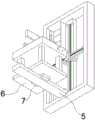
图1为本发明提供的一种光学元件多自由度检测装置的一种较佳实施例的结构示意图;Fig. 1 is a schematic structural view of a preferred embodiment of an optical element multi-degree-of-freedom detection device provided by the present invention;
图2为图1所示的一种光学元件多自由度检测装置的下视角的结构示意图;Fig. 2 is a structural schematic diagram of a lower viewing angle of an optical element multi-degree-of-freedom detection device shown in Fig. 1;
图3为图1所示的运动台的结构示意图;Fig. 3 is a schematic structural view of the motion platform shown in Fig. 1;
图4为图1所示的运动台右视角的结构示意图;Fig. 4 is a schematic structural diagram of the right perspective of the sports platform shown in Fig. 1;
图5为图1所示的光学平台的结构示意图Figure 5 is a schematic structural view of the optical platform shown in Figure 1
图6为图1所示的光学平台右视角的结构示意图;Fig. 6 is a structural schematic diagram of the right angle of view of the optical table shown in Fig. 1;
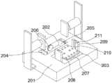
图7为图1所示的光学平台上视角的结构示意图;Fig. 7 is a structural schematic diagram of the viewing angle on the optical table shown in Fig. 1;
图中标号:1、光学平台;2、运动台;3、转动机构;4、CCD摄像机;5、下电动导轨;6、下移动板;7、下滑块;101、固定架;102、纵向电动滑轨;103、纵向滑块;104、横向电动滑轨;105、横向滑块;106、前向电动滑轨;107、前向滑块;108、转动板;109、旋转电机;110、右滑杆;111、右限位槽;112、转轴;113、左滑杆;114、左限位槽;201、放置台;202、放置槽;203、第二放置槽;204、左固定板;205、右固定板;206、前固定板;207、放置板;208、吸附孔;209、右支撑板;210、右滑块;211、右滑槽;212、电动升降杆;213、左滑块;214、左支撑板;215、左滑槽;216、上左板;217、上左电动液压装置;218、上左支撑板;219、上右板;220、上右电动液压装置;221、上右支撑板;222、左电动液压装置;223、右电动液压装置;224、前电动液压装置;225、真空泵。Symbols in the figure: 1, optical platform; 2, motion table; 3, rotating mechanism; 4, CCD camera; 5, lower electric guide rail; 6, lower moving plate; 7, lower slider; 101, fixed frame; Electric slide rail; 103, vertical slide block; 104, horizontal electric slide rail; 105, horizontal slide block; 106, forward electric slide rail; 107, forward slide block; 108, rotating plate; 109, rotating motor; 110, 111, right limit slot; 112, rotating shaft; 113, left slide bar; 114, left limit slot; 201, placement table; 202, placement slot; 203, second placement slot; 204, left fixed plate ; 205, right fixed plate; 206, front fixed plate; 207, place plate; 208, adsorption hole; Slide block; 214, left support plate; 215, left chute; 216, upper left plate; 217, upper left electrohydraulic device; 218, upper left support plate; 219, upper right plate; 220, upper right electrohydraulic device; 221, upper right support plate; 222, left electrohydraulic device; 223, right electrohydraulic device; 224, front electrohydraulic device; 225, vacuum pump.
具体实施方式Detailed ways
为了使本发明实施例的目的、技术方案和优点更加清楚,下面将结合本发明实施例中的附图,对本发明实施例中的技术方案进行清楚、完整地描述,显然,所描述的实施例是本发明一部分实施例,而不是全部的实施例。通常在此处附图中描述和示出的本发明实施例的组件可以以各种不同的配置来布置和设计。In order to make the purpose, technical solutions and advantages of the embodiments of the present invention clearer, the technical solutions in the embodiments of the present invention will be clearly and completely described below in conjunction with the drawings in the embodiments of the present invention. Obviously, the described embodiments It is a part of embodiments of the present invention, but not all embodiments. The components of the embodiments of the invention generally described and illustrated in the figures herein may be arranged and designed in a variety of different configurations.
因此,以下对在附图中提供的本发明的实施例的详细描述并非旨在限制要求保护的本发明的范围,而是仅仅表示本发明的选定实施例。基于本发明中的实施例,本领域普通技术人员在没有作出创造性劳动前提下所获得的所有其他实施例,都属于本发明保护的范围。Accordingly, the following detailed description of the embodiments of the invention provided in the accompanying drawings is not intended to limit the scope of the claimed invention, but merely represents selected embodiments of the invention. Based on the embodiments of the present invention, all other embodiments obtained by persons of ordinary skill in the art without creative efforts fall within the protection scope of the present invention.
应注意到:相似的标号和字母在下面的附图中表示类似项,因此,一旦某一项在一个附图中被定义,则在随后的附图中不需要对其进行进一步定义和解释。It should be noted that like numerals and letters denote similar items in the following figures, therefore, once an item is defined in one figure, it does not require further definition and explanation in subsequent figures.
在本发明实施例的描述中,需要说明的是,若出现术语“中心”、“上”、“下”、“左”、“右”、“竖直”、“水平”、“内”、“外”等指示的方位或位置关系为基于附图所示的方位或位置关系,或者是该发明产品使用时惯常摆放的方位或位置关系,仅是为了便于描述本发明和简化描述,而不是指示或暗示所指的装置或元件必须具有特定的方位、以特定的方位构造和操作,因此不能理解为对本发明的限制。此外,若出现术语“第一”、“第二”、“第三”等仅用于区分描述,而不能理解为指示或暗示相对重要性。In the description of the embodiments of the present invention, it should be noted that if the terms "center", "upper", "lower", "left", "right", "vertical", "horizontal", "inner", The orientation or positional relationship indicated by "outside" is based on the orientation or positional relationship shown in the drawings, or the orientation or positional relationship that is usually placed when the product of the invention is used, and is only for the convenience of describing the present invention and simplifying the description. It is not to indicate or imply that the device or element referred to must have a particular orientation, be constructed in a particular orientation, or operate in a particular orientation, and thus should not be construed as limiting the invention. In addition, the terms "first", "second", "third" and so on are only used for distinguishing descriptions, and should not be understood as indicating or implying relative importance.
此外,若出现术语“水平”、“竖直”、“悬垂”等术语并不表示要求部件绝对水平或悬垂,而是可以稍微倾斜。如“水平”仅仅是指其方向相对“竖直”而言更加水平,并不是表示该结构一定要完全水平,而是可以稍微倾斜。In addition, the appearance of the terms "horizontal", "vertical", "overhanging" etc. does not mean that the parts are absolutely horizontal or overhanging, but may be slightly inclined. For example, "horizontal" only means that its direction is more horizontal than "vertical", and it does not mean that the structure must be completely horizontal, but can be slightly inclined.
在本发明实施例的描述中,还需要说明的是,除非另有明确的规定和限定,若出现术语“设置”、“安装”、“相连”、“连接”应做广义理解,例如,可以是固定连接,也可以是可拆卸连接,或一体地连接;可以是机械连接,也可以是电连接;可以是直接相连,也可以通过中间媒介间接相连,可以是两个元件内部的连通。对于本领域的普通技术人员而言,可以根据具体情况理解上述术语在本发明中的具体含义。In the description of the embodiments of the present invention, it should also be noted that, unless otherwise specified and limited, the terms "setting", "installation", "connection" and "connection" should be interpreted in a broad sense, for example, It can be a fixed connection, a detachable connection, or an integral connection; it can be a mechanical connection or an electrical connection; it can be a direct connection or an indirect connection through an intermediary, and it can be the internal communication of two components. Those of ordinary skill in the art can understand the specific meanings of the above terms in the present invention according to specific situations.
以下结合具体实施例对一种光学元件多自由度检测装置的具体实现进行详细描述。The specific implementation of an optical element multi-degree-of-freedom detection device will be described in detail below in conjunction with specific embodiments.
参考图1至图7,本发明提供的一种光学元件多自由度检测装置,包括:可用于放置光学元件的光学平台1,CCD摄像机4,可将CCD摄像机4上下移动的运动台2,所述CCD摄像机4通过线路连接可对图像处理的图像处理装置;With reference to Fig. 1 to Fig. 7, a kind of multi-degree-of-freedom detection device of optical element provided by the present invention comprises: the
所述光学平台1包括放置台201,所述放置台201的顶部设有放置槽202,所述放置槽202的内部设有左固定板204与右固定板205,所述左固定板204与右固定板205分别固定连接左电动液压装置222与右电动液压装置223的伸缩端,所述左电动液压装置222的固定端安装在放置台201一端的内部,所述右电动液压装置223的固定端安装在放置台201另一端的内部;、Described optical table 1 comprises placing
所述运动台2包括固定架101,所述固定架101固定在放置台201一侧的地面上,所述固定架101的内壁之间安装有可上下移动的纵向电动滑轨102,所述纵向电动滑轨102通过纵向滑块103滑动连接可左右移动的横向电动滑轨104,所述横向电动滑轨104通过横向滑块105滑动连接可前后移动的前向电动滑轨106,所述前向电动滑轨106通过前向滑块107连接转动机构3,所述CCD摄像机4安装在转动机构3上;Described motion table 2 comprises fixed
需要说明的是:图像处理装置,可选用带有图像采集卡以及图像分析系统的计算机,左电动液压装置222与右电动液压装置223通过同一个控制器进行控制,保证左电动液压装置222与右电动液压装置223可同步进行启动以及关闭,并通过设置放置台201,并在放置台201上开设有用于放置原件的放置槽202,可在使用时,将光学元件放置在放置槽202中,并通过位于放置槽202内部的左固定板204与右固定板205,左固定板204与右固定板205可根据使用者的需求进行同步的进行移动,将左固定板204与右固定板205的两端分别与光学元件的两端接触,对光学元件进行固定,保证在检测过程中,光学元件不会受到外力发生位移,提高检测的精度;It should be noted that the image processing device can be a computer with an image acquisition card and an image analysis system, and the left
进一步说明,通过设置固定架101,并在固定架101上安装纵向电动滑轨102、横向电动滑轨104以及前向电动滑轨106,纵向电动滑轨102、横向电动滑轨104以及前向电动滑轨106的丝杆选用滚珠丝杠,通过纵向电动滑轨102、横向电动滑轨104以及前向电动滑轨106,实现了CCD摄像机4的立体运动,并通过设置转动机构3,可通过转动机构3对CCD摄像机4的摄像头朝向进行调整,可对不同形状的光学元件进行识别,提高检测的多样性;To further illustrate, by setting the fixed
还需要说明的是,通过设置运动台2,并将其安装在光学平台1的一侧,可放置CCD摄像机4在移动过程中,产生的振动影响到光学元件放置的稳定,进而影响检测的精度,并且通过运动台2实现了CCD摄像机4的运动,可有效降低了成本,并且便于后续的维修,降低维护成本。It should also be noted that by setting the motion table 2 and installing it on one side of the optical table 1, the vibration generated by the
在本发明的实施例中,参考图3所示,所述转动机构3包括转动板108,所述转动板108固定连接转轴112,所述转轴112通过联轴器旋转连接旋转电机109,所述旋转电机109安装在前向滑块107上,所述CCD摄像机4安装在转动板108上。In an embodiment of the present invention, as shown in FIG. 3 , the
需要说明的是:通过设置旋转电机109,通过旋转电机109可带动转动板108进行旋转,当对一些检测面朝上的光学元件进行检测时,可通过旋转电机109进行旋转,将CCD摄像机4的摄像头朝向进行调整,实现了检测的多样性;It should be noted that: by arranging the
在本发明的实施例中,参考图7所示,所述放置台201的顶部设有第二放置槽203,所述第二放置槽203内部安装有放置板207,所述放置板207的顶部设有吸附孔208,所述吸附孔208通过气管连接真空泵225,所述真空泵225安装在第二放置槽203的内部。In an embodiment of the present invention, as shown in FIG. 7 , the top of the
需要说明的是:通过设置带有吸附孔208的放置板207,可用于放置体积较小,或者曲面结构的光学元件,防止通过固定板对此类光学元件进行夹持时,不能很好的对其固定,影响后续检测的精度;It should be noted that by setting the
在本发明的实施例中,参考图6所示,所述放置板207的底部固定连接电动升降杆212的伸缩端,所述电动升降杆212的固定端安装在第二放置槽203内部的底端。In an embodiment of the present invention, as shown in FIG. 6 , the bottom of the
需要说明的是:通过在放置板207的底部安装有电动升降杆212,可带动放置板207进行上下移动,可调整放置板207的高度,便于CCD摄像机4进行识别,便于后续的检测;It should be noted that: by installing an
在本发明的实施例中,参考图3、图4所示,所述放置板207两端端面固定连接左滑块213与右滑块210,所述左滑块213与右滑块210分别滑动连接左滑槽215与右滑槽211,所述左滑槽215与右滑槽211分别设置在左支撑板214与右支撑板209的端面上,所述左支撑板214与右支撑板209的底部安装在第二放置槽203内部的底端。In an embodiment of the present invention, as shown in FIG. 3 and FIG. 4 , the two ends of the
需要说明的是:通过设置左滑槽215与右滑槽211,通过左滑槽215与右滑槽211对左滑块213与右滑块210的限位,保证放置板207上下移动时的稳定;It should be noted that: by setting the
在本发明的实施例中,参考图4所示,所述放置槽202的内部安装有前固定板206,所述前固定板206的端面固定连接前电动液压装置224的伸缩端,所述前电动液压装置224的固定端安装在放置台201的内部。In the embodiment of the present invention, as shown in FIG. 4 , a
需要说明的是:通过设置多个前固定板206,可在光学元件放置在放置槽202中时,通过前移动板带动多个前固定板206进行移动,将光学元件进行一端与放置槽202内壁接触,保证光学元件放置的稳定;It should be noted that by providing a plurality of front fixing
在本发明的实施例中,参考图6所示,所述放置槽202两侧分别设有上左板216与上右板219,所述上左板216与上右板219分别固定连接上左电动液压装置217与上右电动液压装置220的伸缩端,所述上左电动液压装置217与上右电动液压装置220的固定端分别固定连接上左支撑板218与上右支撑板209,所述上左支撑板218与上右支撑板209的底部分别固定连接放置台201的两端的端面。In an embodiment of the present invention, as shown in FIG. 6, an upper
需要说明的是:通过设置可移动的上左板216与上右板219,可在光学元件固定后,通过控制上左板216与上右板219进行移动,将其端面与光学元件的端面固定连接,保证光学元件放置的稳定;It should be noted that by setting the movable upper
在本发明的实施例中,参考图3、图4所示,所述横向电动滑轨104的两端分别固定连接左滑杆113与右滑杆110,所述左滑杆113与右滑杆110分别滑动连接左限位槽114与右限位槽111,所述左限位槽114与右限位槽111分别滑动连接固定架101内壁的两端。In an embodiment of the present invention, as shown in FIG. 3 and FIG. 4 , the two ends of the horizontal
需要说明的是:通过设置左滑杆113与右滑杆110,并通过左限位槽114与右限位槽111的限位,保证横向电动滑轨104上下移动的稳定。It should be noted that by setting the
在本发明的实施例中,参考图2所示,所述放置台201的底部固定连接下移动板6,所述下移动板6固定连接下滑块7,所述下滑块7滑动连接下电动导轨5In an embodiment of the present invention, as shown in FIG. 2 , the bottom of the placing table 201 is fixedly connected to the lower moving
本发明提供的一种光学元件多自由度检测装置的工作原理如下:The working principle of an optical element multi-degree-of-freedom detection device provided by the present invention is as follows:
通过设置放置台201,并在放置台201上开设有用于放置原件的放置槽202,可在使用时,将光学元件放置在放置槽202中,并通过位于放置槽202内部的左固定板204与右固定板205,左固定板204与右固定板205可根据使用者的需求进行同步的进行移动,将左固定板204与右固定板205的两端分别与光学元件的两端接触,对光学元件进行固定,保证在检测过程中,光学元件不会受到外力发生位移,提高检测的精度,过设置运动台2,并将其安装在光学平台1的一侧,可放置CCD摄像机4在移动过程中,产生的振动影响到光学元件放置的稳定,进而影响检测的精度,并且通过运动台2实现了CCD摄像机4的运动,可有效降低了成本,并且便于后续的维修,降低维护成本。By setting the placement table 201 and opening a
本发明中涉及的电路以及控制均为现有技术,在此不进行过多赘述。The circuits and controls involved in the present invention are all prior art, and will not be repeated here.
以上所述仅为本发明的实施例,并非因此限制本发明的专利范围,凡是利用本发明说明书及附图内容所作的等效结构或等效流程变换,或直接或间接运用在其它相关的技术领域,均同理包括在本发明的专利保护范围内。The above is only an embodiment of the present invention, and does not limit the patent scope of the present invention. Any equivalent structure or equivalent process transformation made by using the description of the present invention and the contents of the accompanying drawings, or directly or indirectly used in other related technologies fields, are all included in the scope of patent protection of the present invention in the same way.
Claims (9)
Translated fromChinesePriority Applications (2)
| Application Number | Priority Date | Filing Date | Title |
|---|---|---|---|
| CN202310579864.2ACN116399883A (en) | 2023-05-22 | 2023-05-22 | A multi-degree-of-freedom detection device for an optical element |
| IE20230585UIE20230585U1 (en) | 2023-05-22 | 2023-12-28 | A multi-degree-of-freedom detection device for optical elements |
Applications Claiming Priority (1)
| Application Number | Priority Date | Filing Date | Title |
|---|---|---|---|
| CN202310579864.2ACN116399883A (en) | 2023-05-22 | 2023-05-22 | A multi-degree-of-freedom detection device for an optical element |
Publications (1)
| Publication Number | Publication Date |
|---|---|
| CN116399883Atrue CN116399883A (en) | 2023-07-07 |
Family
ID=87016266
Family Applications (1)
| Application Number | Title | Priority Date | Filing Date |
|---|---|---|---|
| CN202310579864.2APendingCN116399883A (en) | 2023-05-22 | 2023-05-22 | A multi-degree-of-freedom detection device for an optical element |
Country Status (2)
| Country | Link |
|---|---|
| CN (1) | CN116399883A (en) |
| IE (1) | IE20230585U1 (en) |
Citations (7)
| Publication number | Priority date | Publication date | Assignee | Title |
|---|---|---|---|---|
| JP2006201516A (en)* | 2005-01-20 | 2006-08-03 | Fuji Photo Film Co Ltd | Clamping apparatus, image forming apparatus, and clamping method |
| CN108152299A (en)* | 2017-12-12 | 2018-06-12 | 长光卫星技术有限公司 | The beauty defects detection device and detection method of high-precision optical element |
| CN109724989A (en)* | 2019-02-28 | 2019-05-07 | 广东银宝山新科技有限公司 | Fully automatic optical inspection device |
| CN110400502A (en)* | 2019-07-26 | 2019-11-01 | 邵东智能制造技术研究院有限公司 | Machine vision teaching platform |
| CN215812459U (en)* | 2021-08-16 | 2022-02-11 | 安华精密科技(苏州)有限公司 | Part clamping device for metal part surface detection |
| CN115268332A (en)* | 2022-08-05 | 2022-11-01 | 无锡数科云软件有限公司 | A general-purpose FPGA debugging device |
| CN218856880U (en)* | 2022-11-10 | 2023-04-14 | 武汉安创想智能科技有限公司 | Full-visual semi-automatic multi-dimensional coupling platform |
- 2023
- 2023-05-22CNCN202310579864.2Apatent/CN116399883A/enactivePending
- 2023-12-28IEIE20230585Upatent/IE20230585U1/enunknown
Patent Citations (7)
| Publication number | Priority date | Publication date | Assignee | Title |
|---|---|---|---|---|
| JP2006201516A (en)* | 2005-01-20 | 2006-08-03 | Fuji Photo Film Co Ltd | Clamping apparatus, image forming apparatus, and clamping method |
| CN108152299A (en)* | 2017-12-12 | 2018-06-12 | 长光卫星技术有限公司 | The beauty defects detection device and detection method of high-precision optical element |
| CN109724989A (en)* | 2019-02-28 | 2019-05-07 | 广东银宝山新科技有限公司 | Fully automatic optical inspection device |
| CN110400502A (en)* | 2019-07-26 | 2019-11-01 | 邵东智能制造技术研究院有限公司 | Machine vision teaching platform |
| CN215812459U (en)* | 2021-08-16 | 2022-02-11 | 安华精密科技(苏州)有限公司 | Part clamping device for metal part surface detection |
| CN115268332A (en)* | 2022-08-05 | 2022-11-01 | 无锡数科云软件有限公司 | A general-purpose FPGA debugging device |
| CN218856880U (en)* | 2022-11-10 | 2023-04-14 | 武汉安创想智能科技有限公司 | Full-visual semi-automatic multi-dimensional coupling platform |
Also Published As
| Publication number | Publication date |
|---|---|
| IE20230585U1 (en) | 2025-09-24 |
Similar Documents
| Publication | Publication Date | Title |
|---|---|---|
| CN110398849B (en) | Optical detection system for liquid crystal display screen | |
| CN113259579B (en) | Image acquisition device, method and equipment | |
| WO2022033391A1 (en) | Super-depth-of-field microscopic quick measurement device and measurement method | |
| CN214747771U (en) | Automatic detection equipment for parts | |
| CN100535590C (en) | Basal lamina determination device | |
| CN111721205A (en) | Non-contact size detection equipment | |
| CN111207682A (en) | Trapezoidal lead screw parameter automatic measuring device and method based on machine vision | |
| CN114252245A (en) | Intelligent glasses visual imaging test platform | |
| CN212483393U (en) | A multi-faceted imaging visual inspection device | |
| CN116643392A (en) | Microscope operating platform with lifting function and application method thereof | |
| CN116399883A (en) | A multi-degree-of-freedom detection device for an optical element | |
| CN206058718U (en) | Optical element coaxial adjustment experimental provision | |
| CN111458336B (en) | Full-automatic inner surface internal vision inspection system | |
| CN112378797A (en) | Full-automatic indentation measuring device and method | |
| CN118131465A (en) | Microscopic imaging system and leveling method | |
| CN109342441A (en) | An AOI automatic level detection device for large-size display panels | |
| CN217032970U (en) | Smart glasses visual imaging test platform | |
| CN218723934U (en) | Automatic detection equipment for large-breadth Mini LED panel | |
| CN214472862U (en) | A flexible circuit board circuit detection device | |
| CN110794567A (en) | Rotatable optical microscope sample clamping device | |
| CN214173247U (en) | Non-contact gear radial runout detection equipment | |
| JP2000258583A (en) | Fuel rod gap measuring device for boiling water nuclear fuel assemblies | |
| CN112082577B (en) | Level telescope focusing operation error calibrating device | |
| CN220120025U (en) | Multi-lens image measuring instrument | |
| CN113030116A (en) | Flexible circuit board line detection device |
Legal Events
| Date | Code | Title | Description |
|---|---|---|---|
| PB01 | Publication | ||
| PB01 | Publication | ||
| SE01 | Entry into force of request for substantive examination | ||
| SE01 | Entry into force of request for substantive examination | ||
| RJ01 | Rejection of invention patent application after publication | Application publication date:20230707 | |
| RJ01 | Rejection of invention patent application after publication |