CN116395133A - A kind of aircraft and tail rotor and ducted tail rotor blade - Google Patents
A kind of aircraft and tail rotor and ducted tail rotor bladeDownload PDFInfo
- Publication number
- CN116395133A CN116395133ACN202310400350.6ACN202310400350ACN116395133ACN 116395133 ACN116395133 ACN 116395133ACN 202310400350 ACN202310400350 ACN 202310400350ACN 116395133 ACN116395133 ACN 116395133A
- Authority
- CN
- China
- Prior art keywords
- tail rotor
- rotor blade
- blade
- ducted
- culvert
- Prior art date
- Legal status (The legal status is an assumption and is not a legal conclusion. Google has not performed a legal analysis and makes no representation as to the accuracy of the status listed.)
- Granted
Links
Images


Classifications
- B—PERFORMING OPERATIONS; TRANSPORTING
- B64—AIRCRAFT; AVIATION; COSMONAUTICS
- B64C—AEROPLANES; HELICOPTERS
- B64C27/00—Rotorcraft; Rotors peculiar thereto
- B64C27/82—Rotorcraft; Rotors peculiar thereto characterised by the provision of an auxiliary rotor or fluid-jet device for counter-balancing lifting rotor torque or changing direction of rotorcraft
- Y—GENERAL TAGGING OF NEW TECHNOLOGICAL DEVELOPMENTS; GENERAL TAGGING OF CROSS-SECTIONAL TECHNOLOGIES SPANNING OVER SEVERAL SECTIONS OF THE IPC; TECHNICAL SUBJECTS COVERED BY FORMER USPC CROSS-REFERENCE ART COLLECTIONS [XRACs] AND DIGESTS
- Y02—TECHNOLOGIES OR APPLICATIONS FOR MITIGATION OR ADAPTATION AGAINST CLIMATE CHANGE
- Y02T—CLIMATE CHANGE MITIGATION TECHNOLOGIES RELATED TO TRANSPORTATION
- Y02T90/00—Enabling technologies or technologies with a potential or indirect contribution to GHG emissions mitigation
Landscapes
- Engineering & Computer Science (AREA)
- Mechanical Engineering (AREA)
- Aviation & Aerospace Engineering (AREA)
- Turbine Rotor Nozzle Sealing (AREA)
Abstract
Description
Translated fromChinese技术领域Technical Field
本发明涉及飞行器及其周边配套设施技术领域,特别是涉及一种飞行器和尾桨及涵道尾桨桨叶。The present invention relates to the technical field of aircraft and peripheral supporting facilities thereof, in particular to an aircraft and a tail rotor and a ducted tail rotor blade.
背景技术Background Art
涵道尾桨是在垂尾中制成筒形涵道,在涵道内装尾桨叶和尾桨毂,利用涵道产生附加气动力。涵道尾桨的桨叶外形对其气动和噪声特性具有重要的影响,针对桨叶气动外形开展设计是提升涵道尾桨性能的主要手段之一。The ducted tail rotor is a cylindrical duct made in the vertical tail, with tail rotor blades and tail rotor hub installed in the duct, and the duct is used to generate additional aerodynamic force. The blade shape of the ducted tail rotor has an important influence on its aerodynamic and noise characteristics. Designing the aerodynamic shape of the blade is one of the main means to improve the performance of the ducted tail rotor.
目前,涵道尾桨的桨叶外形较为常规。其中,翼型主要套用现有旋翼的翼型,而涵道尾桨工作环境与旋翼差异较大,旋翼的翼型难以适用于涵道尾桨中。在三维外形方面,常规涵道尾桨桨叶以线性扭转、单一弦长、矩形平面外形为主,对涵道尾桨气动性能的提升效果有限,且矩形桨叶与定子之间存在较强的气动干扰,增大了涵道尾桨的干扰噪声水平。At present, the blade shape of the ducted tail rotor is relatively conventional. Among them, the airfoil mainly adopts the airfoil of the existing rotor, but the working environment of the ducted tail rotor is quite different from that of the rotor, and the airfoil of the rotor is difficult to be applied to the ducted tail rotor. In terms of three-dimensional shape, the blades of conventional ducted tail rotors are mainly linear torsion, single chord length, and rectangular plane shape, which has limited effect on improving the aerodynamic performance of the ducted tail rotor, and there is strong aerodynamic interference between the rectangular blades and the stator, which increases the interference noise level of the ducted tail rotor.
因此,如何改变现有技术中,涵道尾桨的干扰噪声较强的现状,成为了本领域技术人员亟待解决的问题。Therefore, how to change the current situation in the prior art where the interference noise of the ducted tail rotor is relatively strong has become an urgent problem to be solved by those skilled in the art.
发明内容Summary of the invention
本发明的目的是提供一种飞行器和尾桨及涵道尾桨桨叶,以解决上述现有技术存在的问题,降低涵道尾桨的噪声水平,提升飞行器气动性能。The purpose of the present invention is to provide an aircraft, a tail rotor and a ducted tail rotor blade to solve the problems existing in the above-mentioned prior art, reduce the noise level of the ducted tail rotor and improve the aerodynamic performance of the aircraft.
为实现上述目的,本发明提供了如下方案:本发明提供一种涵道尾桨桨叶,在与所述涵道尾桨桨叶转动轴线相垂直的平面内,所述涵道尾桨桨叶的投影轮廓具有圆弧段;To achieve the above object, the present invention provides the following solution: The present invention provides a ducted tail rotor blade, wherein in a plane perpendicular to the rotation axis of the ducted tail rotor blade, the projection profile of the ducted tail rotor blade has a circular arc segment;
所述涵道尾桨桨叶转动过程中,在与所述涵道尾桨桨叶转动轴线相垂直的平面内,所述涵道尾桨桨叶的投影与涵道尾桨的定子叶片的投影最大重合面积小于所述涵道尾桨的定子叶片的投影面积。During the rotation of the ducted tail rotor blade, in a plane perpendicular to the rotation axis of the ducted tail rotor blade, the maximum overlapping area of the projection of the ducted tail rotor blade and the projection of the stator blade of the ducted tail rotor is smaller than the projection area of the stator blade of the ducted tail rotor.
优选地,沿所述涵道尾桨桨叶的桨根至桨尖的方向,所述涵道尾桨桨叶的投影轮廓线包括多段依次相连的所述圆弧段。Preferably, along the direction from the root to the tip of the ducted tail rotor blade, the projected contour line of the ducted tail rotor blade includes a plurality of circular arc segments connected in sequence.
优选地,沿所述涵道尾桨桨叶的桨根至桨尖的方向,所述圆弧段的弦长呈先减小后增大,再减小再增大的变化趋势。Preferably, along the direction from the root to the tip of the ducted tail rotor blade, the chord length of the arc segment shows a trend of first decreasing and then increasing, then decreasing and then increasing.
优选地,沿所述涵道尾桨桨叶的桨根至桨尖的方向,所述圆弧段按照圆心位于投影内、圆心位于投影外的循环规律分布。Preferably, along the direction from the root to the tip of the ducted tail rotor blade, the arc segments are distributed according to a cyclic rule in which the center of the circle is located inside the projection and the center of the circle is located outside the projection.
优选地,所述涵道尾桨桨叶的上翼面前缘半径较下翼面前缘半径大。Preferably, the leading edge radius of the upper wing of the ducted tail rotor blade is larger than the leading edge radius of the lower wing.
优选地,所述涵道尾桨桨叶的翼型遵循下列公式:Preferably, the airfoil of the ducted tail rotor blade complies with the following formula:
上翼面:Upper wing surface:

式一中,Ai为上翼面参数,如下表所示:In

下翼面:Lower wing surface:

式二中,Bi为上翼面参数,如下表所示:In


式一和式二中,x和y为以弦长进行无量纲,即弦长为1时的坐标值,不同桨叶展向位置的翼型坐标对应乘以当地的弦长长度,yu为上翼面坐标值,yl为下翼面坐标值;In
非线性弦长分布,弦长分布公式为:Nonlinear chord length distribution, the chord length distribution formula is:

式三中,x为展向位置与桨叶半径的比值,y为弦长与桨叶半径的比值,Ci为弦长公式参数,如下表所示:In

非线性扭转分布,扭转分布公式为:Nonlinear torsion distribution, the torsion distribution formula is:

式四中,x为展向位置与桨叶半径的比值,y为该展向位置的扭转角度,Di为扭转公式参数,如下表所示:In formula 4, x is the ratio of the spanwise position to the blade radius, y is the torsion angle at the spanwise position, andDi is the torsion formula parameter, as shown in the following table:


四分之一弦线位置分布:Quarter chord position distribution:

式五中,x为展向位置与桨叶半径的比值,y为该展向位置四分之一弦线位置的移动量与桨叶半径的比值,以0.432R展向位置为基准,即0.432R展向位置处移动量为0,R为所述涵道尾桨桨叶的半径,数值为正表示向桨叶前缘移动,数值为负表示向桨叶后缘移动,Ei为四分之一弦线位置分布参数,如下表所示:In Formula 5, x is the ratio of the spanwise position to the blade radius, y is the ratio of the movement of the quarter-chord position of the spanwise position to the blade radius, the spanwise position of 0.432R is taken as the reference, that is, the movement at the spanwise position of 0.432R is 0, R is the radius of the ducted tail rotor blade, a positive value indicates movement toward the leading edge of the blade, a negative value indicates movement toward the trailing edge of the blade, and Ei is the quarter-chord position distribution parameter, as shown in the following table:

本发明还提供一种尾桨,包含上述的涵道尾桨桨叶。The present invention also provides a tail rotor, comprising the above-mentioned ducted tail rotor blade.
本发明还提供一种飞行器,包含上述的尾桨。The present invention also provides an aircraft, comprising the above-mentioned tail rotor.
本发明相对于现有技术取得了以下技术效果:Compared with the prior art, the present invention has achieved the following technical effects:
本发明的涵道尾桨桨叶,改变现有技术中矩形平面的桨叶外形,构建弯曲外形的涵道尾桨桨叶,使得涵道尾桨桨叶在转动过程中,涵道尾桨桨叶的投影不会与涵道尾桨的定子叶片的投影完全重合,从而降低涵道尾桨桨叶旋转通过定子叶片上方时发生的遮挡干扰,降低噪声水平。The ducted tail rotor blade of the present invention changes the rectangular plane blade shape in the prior art and constructs a ducted tail rotor blade with a curved shape, so that during the rotation of the ducted tail rotor blade, the projection of the ducted tail rotor blade will not completely overlap with the projection of the stator blade of the ducted tail rotor, thereby reducing the obstruction interference caused by the ducted tail rotor blade rotating over the stator blade and reducing the noise level.
本发明还提供一种包含上述涵道尾桨桨叶的尾桨,有效降低尾桨的干扰噪声水平。同时,本发明还提供一种包含上述尾桨的飞行器,提升飞行器气动性能。The present invention also provides a tail rotor including the above-mentioned ducted tail rotor blade, which effectively reduces the interference noise level of the tail rotor. At the same time, the present invention also provides an aircraft including the above-mentioned tail rotor, which improves the aerodynamic performance of the aircraft.
附图说明BRIEF DESCRIPTION OF THE DRAWINGS
为了更清楚地说明本发明实施例或现有技术中的技术方案,下面将对实施例中所需要使用的附图作简单地介绍,显而易见地,下面描述中的附图仅仅是本发明的一些实施例,对于本领域普通技术人员来讲,在不付出创造性劳动的前提下,还可以根据这些附图获得其他的附图。In order to more clearly illustrate the embodiments of the present invention or the technical solutions in the prior art, the drawings required for use in the embodiments will be briefly introduced below. Obviously, the drawings described below are only some embodiments of the present invention. For ordinary technicians in this field, other drawings can be obtained based on these drawings without paying creative work.
图1为现有技术中的矩形桨叶的结构示意图;FIG1 is a schematic diagram of the structure of a rectangular blade in the prior art;
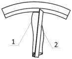
图2为本发明的实施例中所公开的涵道尾桨桨叶的结构示意图;FIG2 is a schematic diagram of the structure of a ducted tail rotor blade disclosed in an embodiment of the present invention;
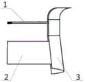
图3为本发明的实施例中所公开的涵道尾桨桨叶工作时的主视图;FIG3 is a front view of the ducted tail rotor blade disclosed in the embodiment of the present invention when in operation;
图4为本发明的实施例中所公开的涵道尾桨桨叶工作时的后视图;FIG4 is a rear view of the ducted tail rotor blades disclosed in an embodiment of the present invention when in operation;
图5为本发明的实施例中所公开的涵道尾桨桨叶工作时的侧视图;FIG5 is a side view of the ducted tail rotor blade disclosed in an embodiment of the present invention when in operation;
图6为本发明的实施例中所公开的涵道尾桨桨叶的翼型图;FIG6 is an airfoil diagram of a ducted tail rotor blade disclosed in an embodiment of the present invention;
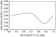
图7为本发明的实施例中所公开的涵道尾桨桨叶的非线性弦长分布图;FIG7 is a nonlinear chord length distribution diagram of a ducted tail rotor blade disclosed in an embodiment of the present invention;
图8为本发明的实施例中所公开的涵道尾桨桨叶的非线性扭转分布图;FIG8 is a nonlinear torsion distribution diagram of a ducted tail rotor blade disclosed in an embodiment of the present invention;
图9为本发明的实施例中所公开的涵道尾桨桨叶的外形分布结构图;FIG9 is a diagram showing the appearance distribution structure of the ducted tail rotor blades disclosed in an embodiment of the present invention;
图10为本发明的实施例一公开的涵道尾桨桨叶与现有技术矩形桨叶的气动性能对比图;FIG10 is a comparison diagram of the aerodynamic performance of the ducted tail rotor blade disclosed in the first embodiment of the present invention and the rectangular blade of the prior art;
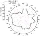
图11为本发明的实施例一公开的涵道尾桨桨叶与现有技术矩形桨叶的涵道尾桨噪声对比图;FIG11 is a comparison diagram of the noise of the ducted tail rotor blade disclosed in the first embodiment of the present invention and the ducted tail rotor blade of the prior art;
图12为本发明的实施例中所公开的尾桨的结构示意图。FIG. 12 is a schematic diagram of the structure of the tail rotor disclosed in an embodiment of the present invention.
其中,1为涵道尾桨桨叶,101为桨根,102为桨尖,2为定子叶片,3为涵道壁面。Among them, 1 is the ducted tail rotor blade, 101 is the rotor root, 102 is the rotor tip, 2 is the stator blade, and 3 is the duct wall.
具体实施方式DETAILED DESCRIPTION
下面将结合本发明实施例中的附图,对本发明实施例中的技术方案进行清楚、完整地描述,显然,所描述的实施例仅仅是本发明一部分实施例,而不是全部的实施例。基于本发明中的实施例,本领域普通技术人员在没有做出创造性劳动前提下所获得的所有其他实施例,都属于本发明保护的范围。The following will be combined with the drawings in the embodiments of the present invention to clearly and completely describe the technical solutions in the embodiments of the present invention. Obviously, the described embodiments are only part of the embodiments of the present invention, not all of the embodiments. Based on the embodiments of the present invention, all other embodiments obtained by ordinary technicians in this field without creative work are within the scope of protection of the present invention.
本发明的目的是提供一种飞行器和尾桨及涵道尾桨桨叶,以解决上述现有技术存在的问题,降低涵道尾桨的噪声水平,提升飞行器气动性能。The purpose of the present invention is to provide an aircraft, a tail rotor and a ducted tail rotor blade to solve the problems existing in the above-mentioned prior art, reduce the noise level of the ducted tail rotor and improve the aerodynamic performance of the aircraft.
为使本发明的上述目的、特征和优点能够更加明显易懂,下面结合附图和具体实施方式对本发明作进一步详细的说明。In order to make the above-mentioned objects, features and advantages of the present invention more obvious and easy to understand, the present invention is further described in detail below with reference to the accompanying drawings and specific embodiments.
本发明提供一种涵道尾桨桨叶1,在与涵道尾桨桨叶1转动轴线相垂直的平面内,涵道尾桨桨叶1的投影轮廓具有圆弧段;涵道尾桨桨叶1转动过程中,在与涵道尾桨桨叶1转动轴线相垂直的平面内,涵道尾桨桨叶1的投影与涵道尾桨的定子叶片2的投影最大重合面积小于涵道尾桨的定子叶片2的投影面积。The present invention provides a ducted
本发明的涵道尾桨桨叶1,改变现有技术中矩形平面的桨叶外形,构建弯曲外形的涵道尾桨桨叶1,使得涵道尾桨桨叶1在转动过程中,涵道尾桨桨叶1的投影不会与涵道尾桨的定子叶片2的投影完全重合,从而降低涵道尾桨桨叶1旋转通过定子叶片2上方时发生的遮挡干扰,降低噪声水平。The ducted
在实际应用中,沿涵道尾桨桨叶1的桨根101至桨尖102的方向,涵道尾桨桨叶1的投影轮廓线可设置为包括多段依次相连的圆弧段,在涵道尾桨桨叶1转动过程中,从而进一步减小涵道尾桨桨叶1的投影与涵道尾桨的定子叶片2的投影重合面积,有利于降低噪声水平。In practical applications, along the direction from the
其中,沿涵道尾桨桨叶1的桨根101至桨尖102的方向,圆弧段的弦长呈先减小后增大,再减小再增大的变化趋势,构建涵道尾桨桨叶1的非线性弦长分布。此处需要解释说明的是,弦长的变化趋势呈现减小-增大-减小-增大的变化趋势,即先减小再增大,重复变化两次,得到的涵道尾桨桨叶1的中段弦长较大。Among them, along the direction from the
同时,沿涵道尾桨桨叶1的桨根101至桨尖102的方向,圆弧段按照圆心位于投影内、圆心位于投影外的循环规律分布。At the same time, along the direction from the
涵道尾桨桨叶1的上翼面前缘半径较下翼面前缘半径大,厚度较小,且最大厚度位置靠近前缘,弯度较大且最大弯度位置靠近前缘。The leading edge radius of the upper wing of the ducted
具体地,涵道尾桨桨叶1的翼型遵循下列公式:Specifically, the airfoil of the ducted
上翼面:Upper wing surface:

式一中,Ai为上翼面参数,如下表所示:In

下翼面:Lower wing surface:

式二中,Bi为上翼面参数,如下表所示:In


式一和式二中,x和y为以弦长进行无量纲,即弦长为1时的坐标值,不同桨叶展向位置的翼型坐标对应乘以当地的弦长长度,yu为上翼面坐标值,yl为下翼面坐标值;具体地,涵道尾桨桨叶1的翼型图可参考图6。In
非线性弦长分布,弦长分布公式为:Nonlinear chord length distribution, the chord length distribution formula is:

式三中,x为展向位置与桨叶半径的比值,y为弦长与桨叶半径的比值,Ci为弦长公式参数,如下表所示:In

本发明的涵道尾桨桨叶1的非线性弦长分布图详见图7。The nonlinear chord length distribution diagram of the ducted
非线性扭转分布,扭转分布公式为:Nonlinear torsion distribution, the torsion distribution formula is:

式四中,x为展向位置与桨叶半径的比值,y为该展向位置的扭转角度,Di为扭转公式参数,如下表所示:In formula 4, x is the ratio of the spanwise position to the blade radius, y is the torsion angle at the spanwise position, andDi is the torsion formula parameter, as shown in the following table:

本发明的涵道尾桨桨叶1的非线性扭转分布图详见图8。The nonlinear torsion distribution diagram of the ducted
四分之一弦线位置分布:Quarter chord position distribution:

式五中,x为展向位置与桨叶半径的比值,y为该展向位置四分之一弦线位置的移动量与桨叶半径的比值,以0.432R展向位置为基准(即0.432R展向位置处移动量为0,其中,R为涵道尾桨桨叶1的半径),数值为正表示向桨叶前缘移动,数值为负表示向桨叶后缘移动,Ei为四分之一弦线位置分布参数,如下表所示:In Formula 5, x is the ratio of the spanwise position to the blade radius, y is the ratio of the movement of the quarter-chord position at the spanwise position to the blade radius, and the spanwise position of 0.432R is taken as the reference (i.e., the movement at the spanwise position of 0.432R is 0, where R is the radius of the ducted tail rotor blade 1). A positive value indicates movement toward the leading edge of the blade, and a negative value indicates movement toward the trailing edge of the blade. Ei is the quarter-chord position distribution parameter, as shown in the following table:


更具体地,本发明的涵道尾桨桨叶1的外形分布结构如图9所示,本发明在0.9R至1.0R展向范围内设计了正扭转。本发明通过翼型、弦长和扭转的设计,改善涵道尾桨桨叶1的载荷分布,增大桨尖102载荷,加速桨尖102处涵道壁面3的气流,改变涵道壁面3的压强分布,进而增加涵道拉力,提升涵道尾桨整体气动性能。此外,通过改变涵道尾桨桨叶1展向不同位置剖面翼型的四分之一弦线中心,得到了从桨根101至桨尖102先后掠-再前掠的弯曲平面外形,减小桨叶旋转通过定子时的遮挡干扰,降低涵道尾桨的噪声水平。More specifically, the shape distribution structure of the ducted
除此之外,还需要说明的是,本发明的涵道尾桨桨叶1的桨根101为非设计段,主要起到涵道尾桨桨叶1与其他结构连接的作用。In addition, it should be noted that the
与此同时,本发明还提供一种尾桨,详见图12,包含上述的涵道尾桨桨叶1,有效改善尾桨的干扰噪声水平。At the same time, the present invention also provides a tail rotor, as shown in FIG. 12 , which includes the above-mentioned ducted
进一步地,本发明还提供一种飞行器,包含上述的尾桨,从而提升飞行器的气动性能。Furthermore, the present invention also provides an aircraft, comprising the above-mentioned tail rotor, so as to improve the aerodynamic performance of the aircraft.
下面通过具体的实施例对本发明的涵道尾桨桨叶1,进行进一步的解释说明。The ducted
实施例一
本实施例以涵道尾桨桨叶1的半径为547毫米为例,下表给出了涵道尾桨桨叶1的具体外形数据。In this embodiment, the radius of the ducted
表1本实施例的涵道尾桨桨叶1的翼型Table 1 Airfoil of the ducted


表2本实施例的涵道尾桨桨叶1的非线性扭转分布Table 2 Nonlinear torsion distribution of the ducted


表3本实施例的涵道尾桨桨叶1的非线性弦长分布Table 3 Nonlinear chord length distribution of the ducted
表4本实施例的涵道尾桨桨叶1的四分之一弦线位置移动量Table 4 Quarter chord position movement of the ducted


本实施例的涵道尾桨桨叶1,与现有技术中矩形桨叶的气动、噪声性能相比,请参考图10和图11,本实施例的涵道尾桨桨叶1提升了涵道尾桨的最大悬停效率,推迟了大拉力下的失速,同时降低了涵道尾桨的噪声。The ducted
本发明中应用了具体个例对本发明的原理及实施方式进行了阐述,以上实施例的说明只是用于帮助理解本发明的方法及其核心思想;同时,对于本领域的一般技术人员,依据本发明的思想,在具体实施方式及应用范围上均会有改变之处。综上所述,本说明书内容不应理解为对本发明的限制。The present invention uses specific examples to illustrate the principles and implementation methods of the present invention. The above examples are only used to help understand the method and core ideas of the present invention. At the same time, for those skilled in the art, according to the ideas of the present invention, there will be changes in the specific implementation methods and application scope. In summary, the content of this specification should not be understood as limiting the present invention.
Claims (8)


Priority Applications (1)
| Application Number | Priority Date | Filing Date | Title |
|---|---|---|---|
| CN202310400350.6ACN116395133B (en) | 2023-04-13 | 2023-04-13 | Aircraft, tail rotor and ducted tail rotor blade |
Applications Claiming Priority (1)
| Application Number | Priority Date | Filing Date | Title |
|---|---|---|---|
| CN202310400350.6ACN116395133B (en) | 2023-04-13 | 2023-04-13 | Aircraft, tail rotor and ducted tail rotor blade |
Publications (2)
| Publication Number | Publication Date |
|---|---|
| CN116395133Atrue CN116395133A (en) | 2023-07-07 |
| CN116395133B CN116395133B (en) | 2024-05-14 |
Family
ID=87008768
Family Applications (1)
| Application Number | Title | Priority Date | Filing Date |
|---|---|---|---|
| CN202310400350.6AActiveCN116395133B (en) | 2023-04-13 | 2023-04-13 | Aircraft, tail rotor and ducted tail rotor blade |
Country Status (1)
| Country | Link |
|---|---|
| CN (1) | CN116395133B (en) |
Citations (10)
| Publication number | Priority date | Publication date | Assignee | Title |
|---|---|---|---|---|
| CN1036182A (en)* | 1988-03-07 | 1989-10-11 | 国家航空工业公司 | Autogiro High Performance shrouded propeller blade, its many blades shrouded propeller and shrouded propeller tail-rotor device |
| US5295643A (en)* | 1992-12-28 | 1994-03-22 | Hughes Missile Systems Company | Unmanned vertical take-off and landing, horizontal cruise, air vehicle |
| JP2009264189A (en)* | 2008-04-23 | 2009-11-12 | Toyota Motor Corp | Rotator of chip turbine fan |
| US20130323043A1 (en)* | 2012-02-27 | 2013-12-05 | Eurocopter | Rotor blade, a rotor, an aircraft, and a method |
| CN103693187A (en)* | 2013-12-13 | 2014-04-02 | 吉林大学 | Wing structure |
| US20170152019A1 (en)* | 2015-11-30 | 2017-06-01 | General Electric Company | Airfoil for a rotary machine including a propellor assembly |
| CN109533311A (en)* | 2018-11-16 | 2019-03-29 | 中国直升机设计研究所 | A kind of high-performance ducted fan |
| FR3082230A1 (en)* | 2018-06-11 | 2019-12-13 | Safran Aircraft Engines | NON-HULL ROTOR AIRCRAFT ENGINE WITH ADAPTATION OF STATOR BLADES |
| US20200325910A1 (en)* | 2017-10-05 | 2020-10-15 | Japan Aerospace Exploration Agency | Ducted fan, multicopter, vertical take-off and landing aircraft, cpu-cooling fan, and radiator-cooling fan |
| US20210114720A1 (en)* | 2019-10-22 | 2021-04-22 | Bell Textron Inc. | Aircraft with Rotating Ducted Fan |
- 2023
- 2023-04-13CNCN202310400350.6Apatent/CN116395133B/enactiveActive
Patent Citations (10)
| Publication number | Priority date | Publication date | Assignee | Title |
|---|---|---|---|---|
| CN1036182A (en)* | 1988-03-07 | 1989-10-11 | 国家航空工业公司 | Autogiro High Performance shrouded propeller blade, its many blades shrouded propeller and shrouded propeller tail-rotor device |
| US5295643A (en)* | 1992-12-28 | 1994-03-22 | Hughes Missile Systems Company | Unmanned vertical take-off and landing, horizontal cruise, air vehicle |
| JP2009264189A (en)* | 2008-04-23 | 2009-11-12 | Toyota Motor Corp | Rotator of chip turbine fan |
| US20130323043A1 (en)* | 2012-02-27 | 2013-12-05 | Eurocopter | Rotor blade, a rotor, an aircraft, and a method |
| CN103693187A (en)* | 2013-12-13 | 2014-04-02 | 吉林大学 | Wing structure |
| US20170152019A1 (en)* | 2015-11-30 | 2017-06-01 | General Electric Company | Airfoil for a rotary machine including a propellor assembly |
| US20200325910A1 (en)* | 2017-10-05 | 2020-10-15 | Japan Aerospace Exploration Agency | Ducted fan, multicopter, vertical take-off and landing aircraft, cpu-cooling fan, and radiator-cooling fan |
| FR3082230A1 (en)* | 2018-06-11 | 2019-12-13 | Safran Aircraft Engines | NON-HULL ROTOR AIRCRAFT ENGINE WITH ADAPTATION OF STATOR BLADES |
| CN109533311A (en)* | 2018-11-16 | 2019-03-29 | 中国直升机设计研究所 | A kind of high-performance ducted fan |
| US20210114720A1 (en)* | 2019-10-22 | 2021-04-22 | Bell Textron Inc. | Aircraft with Rotating Ducted Fan |
Non-Patent Citations (3)
| Title |
|---|
| 倪同兵;招启军;赵国庆;高延达;徐国华;: "应用多块对接结构网格方法的直升机涵道尾桨气动特性分析", 空气动力学学报, no. 06, 15 December 2011 (2011-12-15), pages 689 - 695* |
| 杨福根;: "轻型直升机涵道尾桨的研究", 直升机技术, no. 01, 31 December 2005 (2005-12-31), pages 47 - 49* |
| 王强: "矢量推进式直升机涵道尾桨设计研究", 航空维修与工程, 15 May 2013 (2013-05-15), pages 63 - 64* |
Also Published As
| Publication number | Publication date |
|---|---|
| CN116395133B (en) | 2024-05-14 |
Similar Documents
| Publication | Publication Date | Title |
|---|---|---|
| KR101713264B1 (en) | A blade for a helicopter anti-torque device | |
| CN106919749B (en) | Low-noise wind turbine blade design method and low-noise wind turbine blade | |
| CN114444196B (en) | Design method and device for self-adaptive gap-adjusting variable camber guide vane | |
| CN109505790B (en) | Axial flow fan with high load and high flow capacity | |
| CN115013089B (en) | Design method and system for rectifying support plate of turbine rear case with wide operating condition and rearward shielding | |
| CN113090580B (en) | Centrifugal impeller blade with S-shaped leading edge and molding method thereof | |
| CN114506443B (en) | Blade with guide structure, rotor, and blade design method | |
| CN115062438A (en) | A design method for front rotor blades with curved tip configuration to reduce open rotor noise | |
| CN104963808A (en) | Wind generator blade having W-shaped tips and wind generator | |
| CN116395133B (en) | Aircraft, tail rotor and ducted tail rotor blade | |
| JPH10226397A (en) | Helicopter blade airfoil | |
| CN108757568B (en) | Axial fan blade | |
| CN118260874B (en) | Method for obtaining airfoil profile parameters of corner guide vane | |
| CN101158991A (en) | Aerodynamic Design Method of Large and Small Blade Compressor | |
| CN217682348U (en) | Axial flow fan blade and axial flow fan | |
| CN116822172A (en) | Tandem double-wind-wheel wind turbine pneumatic calculation method and system based on lifting surface | |
| CN212360302U (en) | Guide vane of an axial flow fan and axial flow fan | |
| JPH11124093A (en) | Aerofoil for helicopter blade | |
| CN115495889A (en) | A Design Method of Compressor Rotor with Small Hub Ratio | |
| CN223035351U (en) | Rear guide vane assembly, axial flow fan and air conditioner | |
| CN114607627B (en) | Axial flow fan blade and axial flow fan | |
| JP6709741B2 (en) | Rotor | |
| CN104214137B (en) | Propeller type fan | |
| CN112648235B (en) | Transonic compressor rotor blade with bulge and concave seam structure | |
| CN221257218U (en) | Bird feather-like shaped axial-flow wind wheel and axial-flow fan |
Legal Events
| Date | Code | Title | Description |
|---|---|---|---|
| PB01 | Publication | ||
| PB01 | Publication | ||
| SE01 | Entry into force of request for substantive examination | ||
| SE01 | Entry into force of request for substantive examination | ||
| GR01 | Patent grant | ||
| GR01 | Patent grant |